EP3420147B1 - Auslaufvorrichtung, die an einem wasserauslauf anbringbar ist - Google Patents
Auslaufvorrichtung, die an einem wasserauslauf anbringbar ist Download PDFInfo
- Publication number
- EP3420147B1 EP3420147B1 EP18710319.7A EP18710319A EP3420147B1 EP 3420147 B1 EP3420147 B1 EP 3420147B1 EP 18710319 A EP18710319 A EP 18710319A EP 3420147 B1 EP3420147 B1 EP 3420147B1
- Authority
- EP
- European Patent Office
- Prior art keywords
- water
- outlet
- blades
- blade
- tap water
- Prior art date
- Legal status (The legal status is an assumption and is not a legal conclusion. Google has not performed a legal analysis and makes no representation as to the accuracy of the status listed.)
- Active
Links
Images
Classifications
-
- E—FIXED CONSTRUCTIONS
- E03—WATER SUPPLY; SEWERAGE
- E03C—DOMESTIC PLUMBING INSTALLATIONS FOR FRESH WATER OR WASTE WATER; SINKS
- E03C1/00—Domestic plumbing installations for fresh water or waste water; Sinks
- E03C1/02—Plumbing installations for fresh water
- E03C1/08—Jet regulators or jet guides, e.g. anti-splash devices
- E03C1/086—Jet regulators or jet guides, easily mountable on the outlet of taps
-
- A—HUMAN NECESSITIES
- A45—HAND OR TRAVELLING ARTICLES
- A45D—HAIRDRESSING OR SHAVING EQUIPMENT; EQUIPMENT FOR COSMETICS OR COSMETIC TREATMENTS, e.g. FOR MANICURING OR PEDICURING
- A45D27/00—Shaving accessories
- A45D27/46—Devices specially adapted for cleaning or disinfecting shavers or razors
Definitions
- a device of the type mentioned above is characterized in that the device is supplied via several the flow cross-section of emerging from the outlet of the tap tap water tapers tap water, wherein the device as a rotary valve is formed, which comprises a plurality of mutually common axis below each at least one channel juxtaposed blades which direct the tap water to a water outlet.
- the device according to the invention which is also referred to here as a discharge device, comprises at least one device 21 designed to produce a pulsating water jet and / or to increase the flow speed of the tap water emerging from the outlet of the faucet.
- This device 21 is advantageously designed such that in that, when the faucet is opened, the impending water pressure is passed through a channel plate 28 having a plurality of channels 22a, 22b, 22c (bores) in a row which strike the rotary valve.
- the device 1 further comprises at least one water outlet 24.
- the blades 220a, 220b, 220c are arranged offset on the axis 23 at a defined angle to each other.
- the axis 23 is rotated by at least one blade 220a, 220b, 220c by means of the tap water exiting from the at least one respective channel 22a, 22b, 22c of the faucet.
- the arrangement of the blades 220a, 220b, 220c designed such that the tap water at least one channel 22a, 22b, 22c depending on the rotational position of the blades 220a, 220b, 220c either by at least one blade 220a, 220b, 220c retained or flows through at least one blade 220a, 220b, 220c to a water outlet 24.
- the alternating flow of the tap water through the rotating blades 220a, 220b, 220c produces a pulsating water jet with a water pressure provided as a function of the design of the diameter of the channels 22a, 22b, 22c.
- the device according to the invention is not limited in its execution to the above-mentioned preferred embodiments. Rather, a variety of design variations are possible, which make use of the solution shown even with fundamentally different type of execution.
- the present invention relates to a device (1) for cleaning, for example, a mono- or multi-bladed wet razor blade head, comprising a housing (2) which comprises a water flow opening (20) which can be attached to an outlet of a sanitary outlet fitting, which at least one inside the housing (2 ) of the device (1) and designed to generate at least one pulsating water jet and / or to increase the flow velocity of the effluent from the outlet of the tap tap water formed means (21).
Landscapes
- Health & Medical Sciences (AREA)
- Life Sciences & Earth Sciences (AREA)
- Engineering & Computer Science (AREA)
- Hydrology & Water Resources (AREA)
- Public Health (AREA)
- Water Supply & Treatment (AREA)
- Domestic Plumbing Installations (AREA)
- Nozzles (AREA)
Description
- Die vorliegende Erfindung betrifft eine Auslaufvorrichtung mit einem Gehäuse, das mittels einer Wasserdurchflussöffnung an einem Wasserauslauf einer sanitären Auslaufarmatur anbringbar ist, wobei sich der Wasserdurchflussöffnung mindestens eine innerhalb des Gehäuses der Vorrichtung angeordnete und zur Erzeugung mindestens eines pulsierenden Wasserstrahls und/oder zur Erhöhung der Fließgeschwindigkeit des aus dem Wasserauslauf der Auslaufarmatur austretenden Leitungswassers ausgebildete Einrichtung anschließt.
- Es ist bekannt, dass sich mittels eines üblichen Wasserhahns Nassrasiererklingenköpfe nur sehr schwer reinigen lassen. Der aus dem Wasserhahn austretende Wasserstrahl ist zu weich, um eine ausreichende Reinigung zu erzielen. Dies ist unter anderem dem Umstand geschuldet, dass der Wasserstrahl mittels eines belüfteten Strahlreglers, eines sogenannten Strahlbelüfters, mit Luft vermischt wird.
- Aus dem Stand der Technik sind bereits Einrichtungen bekannt, die dieses Problem zu lösen versuchen. So beschreibt die
DE 10 2009 060 433 A1 einen Aufsatz für einen Auslass eines Wasserhahns, welcher aus einer Kappe gebildet ist, die einen eine Durchflussöffnung bildenden Schlitz aufweist, aus dem das Wasser austritt. - Aus der
DE 20 2006 004 971 U1 ist ein Reinigungsstrahler für Hauswasserhähne bekannt, der an dem Auslaufrohr oder dem an diesem angeschraubten Wasserstrahlbelüfter selbsthaltend angeordnet ist. An seinem Auslass sind Strahlbohrungen angeordnet, welche zur Erzeugung von Wasserstrahlen ausgebildet sind, die eine reinigende Wirkung ausüben können, ohne mit den anderen, jeweils benachbarten Wasserstrahlen zu einem Gesamtstrahl zusammenzufallen. - Aus der
US 4,838,949 A ist weiterhin eine Vorrichtung zum Reinigen eines Nassrasiererklingenkopfes bekannt, die eine in eine Kammer gerichtete Durchflussöffnung umfasst, wobei das Leitungswasser von einer in der Kammer befindlichen Ablenkplatte auf den in die Kammer einführbaren Nassrasiererklingenkopf angestrahlt wird. - Aus der
US 4, 941, 492 A ist eine Vorrichtung zum Spülen eines Rasierklingenkopfes bekannt, welche auf einem Wasserhahn aufgesetzt werden kann und Leitungswasser bei Leitungsdruck aufnimmt. Die Vorrichtung kanalisiert das Leitungswasser zur Erhöhung der Fließgeschwindigkeit, um daraus einen unter "Hochdruck" gerichteten Wasserstrahl zum Reinigen von Rasierklingen zu schaffen. Die Rasierklinge wird in einen unteren Hohlraum der Vorrichtung eingeführt, wo sie von dem Wasserstrahl durch Leitungswasser gereinigt wird, das unter hohem Druck durch eine Reihe von Leitungen in den Hohlraum geleitet wird. - Nachteilig bei den vorgenannten Vorrichtungen ist auf der einen Seite die teils konstruktiv aufwendige Gestaltung, auf der anderen Seite sind diese Vorrichtungen größtenteils nicht geeignet, einen ausreichenden Druck zur Reinigung eines Nassrasiererklingenkopfes zu erzeugen, da der Wasserstrahl aus dem Wasserauslauf hier permanent auf die Rasierklingen bzw. auf die Zwischenräume drückt, was bewirkt, dass sich die rasierten Bartstoppel weiter in die Zwischenräume verkeilen und dort hängen bleiben. Der Querschnitt des auftreffenden Wasserstrahls ist trotz der vorgeschlagenen Konstruktion immer noch so groß, dass die Bartstoppel schlecht entweichen können. Überdies ist der Strahldruck und die Strahlgeschwindigkeit bei den bekannten Einrichtungen als mäßig anzusehen.
- Der vorliegenden Erfindung liegt die Aufgabe zu Grunde, eine Vorrichtung zu schaffen, welche die vorgenannten Probleme ausräumt und die geeignet ist, mehrere, vom Querschnitt kleine Wasserstrahlen, insbesondere Reinigungsstrahlen, abwechselnd beispielsweise über die Längsfläche einer Rasierklinge, pulsieren zu lassen.
- Erfindungsgemäß wird die voranstehende Aufgabe gemäß dem Oberbegriff des Anspruchs 1 in Verbindung mit den kennzeichnenden Merkmalen gelöst. Vorteilhafte Ausgestaltungen und Weiterbildungen der erfindungsgemäßen Vorrichtung sind in den abhängigen Unteransprüchen angegeben.
- In Anlehnung an den genannten Stand der Technik umfasst die erfindungsgemäße Vorrichtung ein Gehäuse, welches an einem Auslass eines Wasserhahns anbringbare Wasserdurchflussöffnung umfasst, der sich mindestens eine innerhalb des Gehäuses der Vorrichtung angeordnete und zur Erzeugung mindestens eines pulsierenden Wasserstrahls und/oder zur Erhöhung der Fließgeschwindigkeit des aus dem Auslass des Wasserhahns austretenden Leitungswassers ausgebildeten Einrichtung anschließt.
- Erfindungsgemäß ist eine Vorrichtung der eingangs genannten Art dadurch gekennzeichnet, dass der Einrichtung über mehrere den Strömungsquerschnitt des aus dem Auslass des Wasserhahns austretenden Leitungswassers begrenzende Kanäle Leitungswasser zugeführt wird, wobei die Einrichtung als Rotationsventil ausgebildet ist, das mehrere auf einander gemeinsamen Achse unterhalb jeweils mindestens eines Kanals nebeneinander angeordnete Schaufeln umfasst, welche das Leitungswasser zu einem Wasserauslass leiten.
- Weitere Ziele, Merkmale, Vorteile und Anwendungsmöglichkeiten der erfindungsgemäßen Vorrichtung ergeben sich aus der nachfolgenden Beschreibung eines Ausführungsbeispiels anhand der Zeichnung. Dabei bilden alle beschriebenen und/oder bildlich dargestellten Merkmale für sich oder in beliebiger Kombination den Gegenstand der Erfindung, unabhängig von der Zusammenfassung in einzelnen Ansprühen oder deren Rückbeziehung.
- In den Zeichnungen zeigen
-
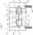
Fig.1 die erfindungsgemäße Vorrichtung in einer schematischen, aufgebrochenen Seitenansicht; -
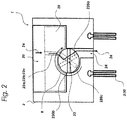
Fig.2 die Vorrichtung in der Frontalansicht. - Wie aus
Fig.1 ersichtlich ist, umfasst die erfindungsgemäße Vorrichtung, die hier auch als Auslaufvorrichtung bezeichnet wird, mindestens eine zur Erzeugung eines pulsierenden Wasserstrahls und/oder zur Erhöhung der Fließgeschwindigkeit des aus dem Auslass des Wasserhahns austretenden Leitungswassers ausgebildete Einrichtung 21. Diese Einrichtung 21 ist vorteilhaft so ausgebildet, dass der anstehende Wasserdruckt beim Öffnen des Wasserhahns durch eine Kanalplatte 28 mit mehreren Kanälen 22a, 22b, 22c (Bohrungen) in einer Reihe durchgeleitet wird, die auf das Rotationsventil treffen. Wie ausFig.1 undFig.2 ersichtlich, umfasst die Vorrichtung 1 ferner mindestens einen Wasserauslass 24. - Wie aus
Fig.1 ersichtlich ist, sind die Schaufeln 220a, 220b, 220c auf der Achse 23 in einem definierten Winkel zueinander versetzt angeordnet. - Mit den Schaufeln 220a, 220b, 220c wird die Achse 23 mittels dem aus dem mindestens einem jeweiligen Kanal 22a, 22b, 22c des Wasserhahns austretenden Leitungswassers durch mindestens eine Schaufel 220a, 220b, 220c in Rotation versetzt.
- Ganz besonders vorteilhaft ist die Anordnung der Schaufeln 220a, 220b, 220c derart ausgelegt, dass das Leitungswasser mindestens eines Kanals 22a, 22b, 22c in Abhängigkeit der Drehposition der Schaufeln 220a, 220b, 220c entweder durch mindestens eine Schaufel 220a, 220b, 220c zurückgehalten oder an mindestens einer Schaufel 220a, 220b, 220c zu einem Wasserauslass 24 durchströmt.
- Die Schaufeln 220a, 220b, 220c in ihrem Winkel zueinander derart versetzt auf der Achse 23 angeordnet sind, dass unabhängig von der jeweiligen Drehposition der Schaufeln 220a, 220b, 220c mindestens eine Schaufel 220a, 220b, 220c ein Durchströmen des Leitungswassers aus mindestens einem Kanal verhindert.
- Durch das abwechselnde Durchströmen des Leitungswassers an den rotierenden Schaufeln 220a, 220b, 220c entsteht ein pulsierender Wasserstrahl mit einem in Abhängigkeit der Ausgestaltung des Durchmessers der Kanäle 22a, 22b, 22c vorgesehenen Wasserdruck.
- Wie aus
Fig.1 ersichtlich, weist die Vorrichtung 1 mindestens eine Lagervorrichtung 25 für eine rotierbare Lagerung der Achse 23 in dem Gehäuse 2 auf. - Weiterhin ist es vorteilhaft, an dem Wasserauslass 24 einen Spritzschutz 3 vorzusehen, welcher aus vertikal ausgerichteten, flexiblen und/oder elastischen sowie kammerartig ausgebildeten Rippen 30 gebildet ist. Der Spritzschutz 23 wird vorzugsweise in einer Ringnut 31 an der Gehäusekammer 2b angeordnet.
- Die Erfindungsgemäße Vorrichtung beschränkt sich in ihrer Ausführung nicht auf die vorstehend angegebenen bevorzugten Ausführungsformen. Vielmehr sind eine Vielzahl von Ausgestaltungsvariationen denkbar, welche von der dargestellten Lösung auch bei grundsätzlich anders gearteter Ausführung Gebrauch machen.
- Die vorliegende Erfindung betrifft eine Vorrichtung (1) zum Reinigen beispielsweise eines ein- oder mehrklingigen Nassrasiererklingenkopfes, mit einem Gehäuse (2), welches eine an einem Auslauf einer sanitären Auslaufarmatur anbringbare Wasserdurchflussöffnung (20) umfasst, der sich mindestens eine innerhalb des Gehäuses (2) der Vorrichtung (1) angeordnete und zur Erzeugung mindestens eines pulsierenden Wasserstrahls und/oder zur Erhöhung der Fließgeschwindigkeit des aus dem Auslass des Wasserhahns austretenden Leitungswassers ausgebildete Einrichtung (21) anschließt. Die erfindungsgemäße Vorrichtung ist dadurch gekennzeichnet, dass der Einrichtung (21) über mehrere den Strömungsquerschnitt des aus dem Wasserauslauf der sanitären Auslaufarmatur austretenden Leitungswassers begrenzte Kanäle (22a, 22b, 22c) Leitungswasser zugeführt wird, wobei die Einrichtung (21) als Rotationsventil ausgebildet ist, das mehrere auf einer gemeinsamen Achse (23) unterhalb jeweils mindestens eines Kanals (22a, 22b, 22c) nebeneinander angeordnete Schaufeln (mehrklingigen) umfasst, welche das Leitungswasser zu einem Wasserauslass (24) leiten.
-
- 1
- Vorrichtung
- 2
- Gehäuse
- 3
- Spritzschutz
- 20
- Wasserdurchflussöffnung
- 21
- Einrichtung
- 22a, 22b, 22c
- wasserleitende Kanäle
- 23
- Achse
- 24
- Wasserauslass
- 25
- Lagervorrichtung
- 26
- Leitungswasser
- 28
- Kanalplatte
- 30
- Rippen
- 220a, 220b, 220c
- Schaufeln
- R
- Rotationsrichtung
Claims (6)
- Vorrichtung (1) insbesondere Auslaufvorrichtung, mit einem Gehäuse (2), das mittels einer Wasserdurchflussöffnung (20) an einem Wasserauslauf einer sanitären Auslaufarmatur anbringbar ist, wobei sich der Wasserdurchflussöffnung (20) mindestens eine innerhalb des Gehäuses (2) der Vorrichtung (1) angeordnete und zur Erzeugung mindestens eines pulsierenden Wasserstrahls und/oder zur Erhöhung der Fließgeschwindigkeit des aus dem Wasserauslauf der sanitären Auslaufarmatur austretenden Leitungswassers ausgebildete Einrichtung (21) anschließt, dadurch gekennzeichnet, dass der Einrichtung (21) über mehrere den Strömungsquerschnitt des aus dem Auslass des Wasserhahns austretenden Leitungswassers begrenzte Kanäle (22a, 22b, 22c) Leitungswasser zugeführt wird, wobei die Einrichtung (21) als Rotationsventil ausgebildet ist, das mehrere auf einer gemeinsamen Achse (23) unterhalb jeweils mindestens eines Kanals (22a, 22b, 22c) nebeneinander angeordnete Schaufeln (220a, 220b, 220c) umfasst, welche das Leitungswasser zu einem Wasserauslass (24) leiten.
- Vorrichtung (1) nach Anspruch 1, dadurch gekennzeichnet, dass die Schaufeln (220a, 220b, 220c) auf der Achse (23) in einem definierten Winkel zueinander versetzt angeordnet sind und die Achse (23) mit den Schaufeln (220a, 220b, 220c) mittels dem aus dem mindestens einen jeweiligen Kanal (22a, 22b, 22c) der sanitären Auslaufarmatur austretenden Leitungswassers durch mindestens eine Schaufel (220a, 220b, 220c) in Rotation versetzt wird.
- Vorrichtung (1) nach Anspruch 2, dadurch gekennzeichnet, dass das Leitungswasser mindestens eines Kanals (22a, 22b, 22c) in Abhängigkeit der Drehposition der Schaufeln (220a, 220b, 220c) entweder durch mindestens eine Schaufel (220a, 220b, 220c) zurückgehalten oder an mindestens einer Schaufel (220a, 220b, 220c) zu einem Wasserauslass (24) durchströmt.
- Vorrichtung (1) nach Anspruch 2 oder 3, dadurch gekennzeichnet, dass die Schaufeln (220a, 220b, 220c) in ihrem Winkel zueinander derart versetzt auf der Achse (23) angeordnet sind, dass unabhängig von der jeweiligen Drehposition der Schaufeln (220a, 220b, 220c) mindestens eine Schaufel (220a, 220b, 220c) ein Durchströmen des Leitungswassers aus mindestens einem Kanal verhindert.
- Vorrichtung (1) nach einem der vorgegangenen Anspruchs dadurch gekennzeichnet, dass sie mindestens eine Lagervorrichtung (25) für eine rotierbare Lagerung der Achse (23) in dem Gehäuse (2) ausweist.
- Vorrichtung (1) nach einem der vorangegangenen Ansprüche, dadurch gekennzeichnet, dass die Vorrichtung (1) zum Reinigen eines ein- oder mehrklingigen Nassrasiererklingenkopfes bestimmt ist.
Applications Claiming Priority (2)
| Application Number | Priority Date | Filing Date | Title |
|---|---|---|---|
| DE102017102491.3A DE102017102491A1 (de) | 2017-02-08 | 2017-02-08 | Vorrichtung zum Reinigen eines Nassrasiererklingenkopfes |
| PCT/EP2018/053062 WO2018146140A1 (de) | 2017-02-08 | 2018-02-07 | Auslaufvorrichtung, die an einem wasserauslauf anbringbar ist |
Publications (2)
| Publication Number | Publication Date |
|---|---|
| EP3420147A1 EP3420147A1 (de) | 2019-01-02 |
| EP3420147B1 true EP3420147B1 (de) | 2019-06-19 |
Family
ID=61622493
Family Applications (1)
| Application Number | Title | Priority Date | Filing Date |
|---|---|---|---|
| EP18710319.7A Active EP3420147B1 (de) | 2017-02-08 | 2018-02-07 | Auslaufvorrichtung, die an einem wasserauslauf anbringbar ist |
Country Status (5)
| Country | Link |
|---|---|
| US (1) | US11499302B2 (de) |
| EP (1) | EP3420147B1 (de) |
| DE (1) | DE102017102491A1 (de) |
| TR (1) | TR201910816T4 (de) |
| WO (1) | WO2018146140A1 (de) |
Family Cites Families (6)
| Publication number | Priority date | Publication date | Assignee | Title |
|---|---|---|---|---|
| US4838949A (en) | 1987-07-20 | 1989-06-13 | Felipe Dugrot | Shaving razor cleaner |
| US4941492A (en) | 1989-05-18 | 1990-07-17 | Morgan Dale D | Razor blade rinsing device |
| DE202006004971U1 (de) | 2006-03-29 | 2006-06-01 | Kalezic, Bozidar | Reinigungsstrahler für Haushaltswasserhähne |
| DE102009060433A1 (de) | 2009-12-22 | 2011-06-30 | Andreas Weller | Aufsatz für einen Auslass eines Wasserhahns |
| AU2011253740B2 (en) * | 2011-11-17 | 2017-02-23 | Luke O'neill | A cleaning device |
| US20140312253A1 (en) | 2011-12-05 | 2014-10-23 | Livne Gan | Compact self powered and automated attachment to a fluid system |
-
2017
- 2017-02-08 DE DE102017102491.3A patent/DE102017102491A1/de not_active Withdrawn
-
2018
- 2018-02-07 US US16/326,790 patent/US11499302B2/en active Active
- 2018-02-07 EP EP18710319.7A patent/EP3420147B1/de active Active
- 2018-02-07 WO PCT/EP2018/053062 patent/WO2018146140A1/de not_active Ceased
- 2018-02-07 TR TR2019/10816T patent/TR201910816T4/tr unknown
Non-Patent Citations (1)
| Title |
|---|
| None * |
Also Published As
| Publication number | Publication date |
|---|---|
| DE102017102491A1 (de) | 2018-08-09 |
| US11499302B2 (en) | 2022-11-15 |
| TR201910816T4 (tr) | 2019-08-21 |
| EP3420147A1 (de) | 2019-01-02 |
| US20210293009A1 (en) | 2021-09-23 |
| WO2018146140A1 (de) | 2018-08-16 |
Similar Documents
| Publication | Publication Date | Title |
|---|---|---|
| DE102005010550B4 (de) | Sanitärer Wasserauslauf | |
| EP1669596B1 (de) | Vorrichtung zur Belüftung einer Rotornabe einer Windenergieanlage | |
| DE102008012388B4 (de) | Sanitäre Funktionseinheit | |
| DE202012002585U1 (de) | Rückfluss-Sperre für eine Unterdusche | |
| EP3447201B1 (de) | Sanitärarmatur mit einschubmechanismus | |
| EP3175923B1 (de) | Brausekopf | |
| WO2018146140A1 (de) | Auslaufvorrichtung, die an einem wasserauslauf anbringbar ist | |
| EP3502362A1 (de) | Sicherungsarmatur | |
| DE2922094A1 (de) | Handbrause | |
| WO2018146141A1 (de) | Auslaufvorrichtung, die an einem wasserauslauf anbringbar ist | |
| DE969426C (de) | Strahlrohr, insbesondere zur Brandbekaempfung | |
| EP1502653B1 (de) | Düse zum Besprühen einer Fläche | |
| DE102005015534B3 (de) | Vorrichtung zur Reinigung von Behältern | |
| EP1213519A2 (de) | Ventil, insbesondere Heizkörperventil | |
| DE7713579U1 (de) | Spruehduese mit einrichtung zur erzeugung eines pulsierenden spruehstrahls | |
| DE2750140C2 (de) | ||
| EP4129489B1 (de) | Flachstrahldüse | |
| DE20317854U1 (de) | Drehbarer Rasensprenger | |
| EP0247532A2 (de) | Reinigungsvorrichtung für Behälter und dergleichen | |
| CH716965B1 (de) | Rohrreinigungsdüse. | |
| DE168230C (de) | ||
| DE1559665C3 (de) | ||
| EP1853770A1 (de) | Sanitäre wasserauslaufarmatur mit strahlrichtungsgeber zum ablenken des austretenden wasserstrahls | |
| EP3101183A1 (de) | Rohrsystem mit spülrohr | |
| DE202006004971U1 (de) | Reinigungsstrahler für Haushaltswasserhähne |
Legal Events
| Date | Code | Title | Description |
|---|---|---|---|
| STAA | Information on the status of an ep patent application or granted ep patent |
Free format text: STATUS: UNKNOWN |
|
| STAA | Information on the status of an ep patent application or granted ep patent |
Free format text: STATUS: THE INTERNATIONAL PUBLICATION HAS BEEN MADE |
|
| PUAI | Public reference made under article 153(3) epc to a published international application that has entered the european phase |
Free format text: ORIGINAL CODE: 0009012 |
|
| STAA | Information on the status of an ep patent application or granted ep patent |
Free format text: STATUS: REQUEST FOR EXAMINATION WAS MADE |
|
| 17P | Request for examination filed |
Effective date: 20180928 |
|
| AK | Designated contracting states |
Kind code of ref document: A1 Designated state(s): AL AT BE BG CH CY CZ DE DK EE ES FI FR GB GR HR HU IE IS IT LI LT LU LV MC MK MT NL NO PL PT RO RS SE SI SK SM TR |
|
| AX | Request for extension of the european patent |
Extension state: BA ME |
|
| GRAP | Despatch of communication of intention to grant a patent |
Free format text: ORIGINAL CODE: EPIDOSNIGR1 |
|
| STAA | Information on the status of an ep patent application or granted ep patent |
Free format text: STATUS: GRANT OF PATENT IS INTENDED |
|
| INTG | Intention to grant announced |
Effective date: 20190226 |
|
| GRAS | Grant fee paid |
Free format text: ORIGINAL CODE: EPIDOSNIGR3 |
|
| GRAA | (expected) grant |
Free format text: ORIGINAL CODE: 0009210 |
|
| STAA | Information on the status of an ep patent application or granted ep patent |
Free format text: STATUS: THE PATENT HAS BEEN GRANTED |
|
| DAV | Request for validation of the european patent (deleted) | ||
| DAX | Request for extension of the european patent (deleted) | ||
| AK | Designated contracting states |
Kind code of ref document: B1 Designated state(s): AL AT BE BG CH CY CZ DE DK EE ES FI FR GB GR HR HU IE IS IT LI LT LU LV MC MK MT NL NO PL PT RO RS SE SI SK SM TR |
|
| REG | Reference to a national code |
Ref country code: GB Ref legal event code: FG4D Free format text: NOT ENGLISH |
|
| REG | Reference to a national code |
Ref country code: CH Ref legal event code: EP |
|
| REG | Reference to a national code |
Ref country code: IE Ref legal event code: FG4D Free format text: LANGUAGE OF EP DOCUMENT: GERMAN |
|
| REG | Reference to a national code |
Ref country code: DE Ref legal event code: R096 Ref document number: 502018000058 Country of ref document: DE |
|
| REG | Reference to a national code |
Ref country code: AT Ref legal event code: REF Ref document number: 1145697 Country of ref document: AT Kind code of ref document: T Effective date: 20190715 |
|
| REG | Reference to a national code |
Ref country code: NL Ref legal event code: MP Effective date: 20190619 |
|
| PG25 | Lapsed in a contracting state [announced via postgrant information from national office to epo] |
Ref country code: AL Free format text: LAPSE BECAUSE OF FAILURE TO SUBMIT A TRANSLATION OF THE DESCRIPTION OR TO PAY THE FEE WITHIN THE PRESCRIBED TIME-LIMIT Effective date: 20190619 Ref country code: LT Free format text: LAPSE BECAUSE OF FAILURE TO SUBMIT A TRANSLATION OF THE DESCRIPTION OR TO PAY THE FEE WITHIN THE PRESCRIBED TIME-LIMIT Effective date: 20190619 Ref country code: HR Free format text: LAPSE BECAUSE OF FAILURE TO SUBMIT A TRANSLATION OF THE DESCRIPTION OR TO PAY THE FEE WITHIN THE PRESCRIBED TIME-LIMIT Effective date: 20190619 Ref country code: FI Free format text: LAPSE BECAUSE OF FAILURE TO SUBMIT A TRANSLATION OF THE DESCRIPTION OR TO PAY THE FEE WITHIN THE PRESCRIBED TIME-LIMIT Effective date: 20190619 Ref country code: SE Free format text: LAPSE BECAUSE OF FAILURE TO SUBMIT A TRANSLATION OF THE DESCRIPTION OR TO PAY THE FEE WITHIN THE PRESCRIBED TIME-LIMIT Effective date: 20190619 Ref country code: NO Free format text: LAPSE BECAUSE OF FAILURE TO SUBMIT A TRANSLATION OF THE DESCRIPTION OR TO PAY THE FEE WITHIN THE PRESCRIBED TIME-LIMIT Effective date: 20190919 |
|
| REG | Reference to a national code |
Ref country code: LT Ref legal event code: MG4D |
|
| PG25 | Lapsed in a contracting state [announced via postgrant information from national office to epo] |
Ref country code: RS Free format text: LAPSE BECAUSE OF FAILURE TO SUBMIT A TRANSLATION OF THE DESCRIPTION OR TO PAY THE FEE WITHIN THE PRESCRIBED TIME-LIMIT Effective date: 20190619 Ref country code: BG Free format text: LAPSE BECAUSE OF FAILURE TO SUBMIT A TRANSLATION OF THE DESCRIPTION OR TO PAY THE FEE WITHIN THE PRESCRIBED TIME-LIMIT Effective date: 20190919 Ref country code: GR Free format text: LAPSE BECAUSE OF FAILURE TO SUBMIT A TRANSLATION OF THE DESCRIPTION OR TO PAY THE FEE WITHIN THE PRESCRIBED TIME-LIMIT Effective date: 20190920 Ref country code: LV Free format text: LAPSE BECAUSE OF FAILURE TO SUBMIT A TRANSLATION OF THE DESCRIPTION OR TO PAY THE FEE WITHIN THE PRESCRIBED TIME-LIMIT Effective date: 20190619 |
|
| PG25 | Lapsed in a contracting state [announced via postgrant information from national office to epo] |
Ref country code: RO Free format text: LAPSE BECAUSE OF FAILURE TO SUBMIT A TRANSLATION OF THE DESCRIPTION OR TO PAY THE FEE WITHIN THE PRESCRIBED TIME-LIMIT Effective date: 20190619 Ref country code: NL Free format text: LAPSE BECAUSE OF FAILURE TO SUBMIT A TRANSLATION OF THE DESCRIPTION OR TO PAY THE FEE WITHIN THE PRESCRIBED TIME-LIMIT Effective date: 20190619 Ref country code: EE Free format text: LAPSE BECAUSE OF FAILURE TO SUBMIT A TRANSLATION OF THE DESCRIPTION OR TO PAY THE FEE WITHIN THE PRESCRIBED TIME-LIMIT Effective date: 20190619 Ref country code: CZ Free format text: LAPSE BECAUSE OF FAILURE TO SUBMIT A TRANSLATION OF THE DESCRIPTION OR TO PAY THE FEE WITHIN THE PRESCRIBED TIME-LIMIT Effective date: 20190619 Ref country code: PT Free format text: LAPSE BECAUSE OF FAILURE TO SUBMIT A TRANSLATION OF THE DESCRIPTION OR TO PAY THE FEE WITHIN THE PRESCRIBED TIME-LIMIT Effective date: 20191021 Ref country code: SK Free format text: LAPSE BECAUSE OF FAILURE TO SUBMIT A TRANSLATION OF THE DESCRIPTION OR TO PAY THE FEE WITHIN THE PRESCRIBED TIME-LIMIT Effective date: 20190619 |
|
| PG25 | Lapsed in a contracting state [announced via postgrant information from national office to epo] |
Ref country code: SM Free format text: LAPSE BECAUSE OF FAILURE TO SUBMIT A TRANSLATION OF THE DESCRIPTION OR TO PAY THE FEE WITHIN THE PRESCRIBED TIME-LIMIT Effective date: 20190619 Ref country code: IS Free format text: LAPSE BECAUSE OF FAILURE TO SUBMIT A TRANSLATION OF THE DESCRIPTION OR TO PAY THE FEE WITHIN THE PRESCRIBED TIME-LIMIT Effective date: 20191019 Ref country code: ES Free format text: LAPSE BECAUSE OF FAILURE TO SUBMIT A TRANSLATION OF THE DESCRIPTION OR TO PAY THE FEE WITHIN THE PRESCRIBED TIME-LIMIT Effective date: 20190619 |
|
| PG25 | Lapsed in a contracting state [announced via postgrant information from national office to epo] |
Ref country code: PL Free format text: LAPSE BECAUSE OF FAILURE TO SUBMIT A TRANSLATION OF THE DESCRIPTION OR TO PAY THE FEE WITHIN THE PRESCRIBED TIME-LIMIT Effective date: 20190619 Ref country code: DK Free format text: LAPSE BECAUSE OF FAILURE TO SUBMIT A TRANSLATION OF THE DESCRIPTION OR TO PAY THE FEE WITHIN THE PRESCRIBED TIME-LIMIT Effective date: 20190619 |
|
| PG25 | Lapsed in a contracting state [announced via postgrant information from national office to epo] |
Ref country code: IS Free format text: LAPSE BECAUSE OF FAILURE TO SUBMIT A TRANSLATION OF THE DESCRIPTION OR TO PAY THE FEE WITHIN THE PRESCRIBED TIME-LIMIT Effective date: 20200224 |
|
| REG | Reference to a national code |
Ref country code: DE Ref legal event code: R097 Ref document number: 502018000058 Country of ref document: DE |
|
| PLBE | No opposition filed within time limit |
Free format text: ORIGINAL CODE: 0009261 |
|
| STAA | Information on the status of an ep patent application or granted ep patent |
Free format text: STATUS: NO OPPOSITION FILED WITHIN TIME LIMIT |
|
| PG2D | Information on lapse in contracting state deleted |
Ref country code: IS |
|
| 26N | No opposition filed |
Effective date: 20200603 |
|
| REG | Reference to a national code |
Ref country code: BE Ref legal event code: MM Effective date: 20200229 |
|
| PG25 | Lapsed in a contracting state [announced via postgrant information from national office to epo] |
Ref country code: MC Free format text: LAPSE BECAUSE OF FAILURE TO SUBMIT A TRANSLATION OF THE DESCRIPTION OR TO PAY THE FEE WITHIN THE PRESCRIBED TIME-LIMIT Effective date: 20190619 Ref country code: LU Free format text: LAPSE BECAUSE OF NON-PAYMENT OF DUE FEES Effective date: 20200207 |
|
| PG25 | Lapsed in a contracting state [announced via postgrant information from national office to epo] |
Ref country code: FR Free format text: LAPSE BECAUSE OF NON-PAYMENT OF DUE FEES Effective date: 20200229 Ref country code: IE Free format text: LAPSE BECAUSE OF NON-PAYMENT OF DUE FEES Effective date: 20200207 |
|
| PG25 | Lapsed in a contracting state [announced via postgrant information from national office to epo] |
Ref country code: BE Free format text: LAPSE BECAUSE OF NON-PAYMENT OF DUE FEES Effective date: 20200229 |
|
| PG25 | Lapsed in a contracting state [announced via postgrant information from national office to epo] |
Ref country code: LI Free format text: LAPSE BECAUSE OF NON-PAYMENT OF DUE FEES Effective date: 20210228 Ref country code: CH Free format text: LAPSE BECAUSE OF NON-PAYMENT OF DUE FEES Effective date: 20210228 |
|
| PG25 | Lapsed in a contracting state [announced via postgrant information from national office to epo] |
Ref country code: MT Free format text: LAPSE BECAUSE OF FAILURE TO SUBMIT A TRANSLATION OF THE DESCRIPTION OR TO PAY THE FEE WITHIN THE PRESCRIBED TIME-LIMIT Effective date: 20190619 Ref country code: CY Free format text: LAPSE BECAUSE OF FAILURE TO SUBMIT A TRANSLATION OF THE DESCRIPTION OR TO PAY THE FEE WITHIN THE PRESCRIBED TIME-LIMIT Effective date: 20190619 |
|
| PGFP | Annual fee paid to national office [announced via postgrant information from national office to epo] |
Ref country code: TR Payment date: 20220127 Year of fee payment: 5 Ref country code: IT Payment date: 20220228 Year of fee payment: 5 |
|
| PG25 | Lapsed in a contracting state [announced via postgrant information from national office to epo] |
Ref country code: MK Free format text: LAPSE BECAUSE OF FAILURE TO SUBMIT A TRANSLATION OF THE DESCRIPTION OR TO PAY THE FEE WITHIN THE PRESCRIBED TIME-LIMIT Effective date: 20190619 |
|
| GBPC | Gb: european patent ceased through non-payment of renewal fee |
Effective date: 20220207 |
|
| PG25 | Lapsed in a contracting state [announced via postgrant information from national office to epo] |
Ref country code: GB Free format text: LAPSE BECAUSE OF NON-PAYMENT OF DUE FEES Effective date: 20220207 |
|
| PGFP | Annual fee paid to national office [announced via postgrant information from national office to epo] |
Ref country code: DE Payment date: 20230310 Year of fee payment: 6 |
|
| PG25 | Lapsed in a contracting state [announced via postgrant information from national office to epo] |
Ref country code: SI Free format text: LAPSE BECAUSE OF FAILURE TO SUBMIT A TRANSLATION OF THE DESCRIPTION OR TO PAY THE FEE WITHIN THE PRESCRIBED TIME-LIMIT Effective date: 20190619 |
|
| PG25 | Lapsed in a contracting state [announced via postgrant information from national office to epo] |
Ref country code: IT Free format text: LAPSE BECAUSE OF NON-PAYMENT OF DUE FEES Effective date: 20230207 |
|
| REG | Reference to a national code |
Ref country code: AT Ref legal event code: MM01 Ref document number: 1145697 Country of ref document: AT Kind code of ref document: T Effective date: 20230207 |
|
| PG25 | Lapsed in a contracting state [announced via postgrant information from national office to epo] |
Ref country code: AT Free format text: LAPSE BECAUSE OF NON-PAYMENT OF DUE FEES Effective date: 20230207 |
|
| PG25 | Lapsed in a contracting state [announced via postgrant information from national office to epo] |
Ref country code: AT Free format text: LAPSE BECAUSE OF NON-PAYMENT OF DUE FEES Effective date: 20230207 |
|
| REG | Reference to a national code |
Ref country code: DE Ref legal event code: R119 Ref document number: 502018000058 Country of ref document: DE |
|
| PG25 | Lapsed in a contracting state [announced via postgrant information from national office to epo] |
Ref country code: DE Free format text: LAPSE BECAUSE OF NON-PAYMENT OF DUE FEES Effective date: 20240903 |
|
| PG25 | Lapsed in a contracting state [announced via postgrant information from national office to epo] |
Ref country code: DE Free format text: LAPSE BECAUSE OF NON-PAYMENT OF DUE FEES Effective date: 20240903 |
|
| PGFP | Annual fee paid to national office [announced via postgrant information from national office to epo] |
Ref country code: AT Payment date: 20260410 Year of fee payment: 5 |
|
| PG25 | Lapsed in a contracting state [announced via postgrant information from national office to epo] |
Ref country code: TR Free format text: LAPSE BECAUSE OF NON-PAYMENT OF DUE FEES Effective date: 20230207 |