EP3418753B1 - Verarbeitungsverfahren eines durch rauschen gestörten signals der motorwellen-drehgeschwindigkeit eines luftfahrzeugs - Google Patents
Verarbeitungsverfahren eines durch rauschen gestörten signals der motorwellen-drehgeschwindigkeit eines luftfahrzeugs Download PDFInfo
- Publication number
- EP3418753B1 EP3418753B1 EP18177655.0A EP18177655A EP3418753B1 EP 3418753 B1 EP3418753 B1 EP 3418753B1 EP 18177655 A EP18177655 A EP 18177655A EP 3418753 B1 EP3418753 B1 EP 3418753B1
- Authority
- EP
- European Patent Office
- Prior art keywords
- signal
- shaft
- switching
- window signal
- speed
- Prior art date
- Legal status (The legal status is an assumption and is not a legal conclusion. Google has not performed a legal analysis and makes no representation as to the accuracy of the status listed.)
- Active
Links
Images




Classifications
-
- G—PHYSICS
- G01—MEASURING; TESTING
- G01P—MEASURING LINEAR OR ANGULAR SPEED, ACCELERATION, DECELERATION, OR SHOCK; INDICATING PRESENCE, ABSENCE, OR DIRECTION, OF MOVEMENT
- G01P3/00—Measuring linear or angular speed; Measuring differences of linear or angular speeds
- G01P3/42—Devices characterised by the use of electric or magnetic means
- G01P3/44—Devices characterised by the use of electric or magnetic means for measuring angular speed
- G01P3/48—Devices characterised by the use of electric or magnetic means for measuring angular speed by measuring frequency of generated current or voltage
- G01P3/4802—Devices characterised by the use of electric or magnetic means for measuring angular speed by measuring frequency of generated current or voltage by using electronic circuits in general
-
- G—PHYSICS
- G01—MEASURING; TESTING
- G01P—MEASURING LINEAR OR ANGULAR SPEED, ACCELERATION, DECELERATION, OR SHOCK; INDICATING PRESENCE, ABSENCE, OR DIRECTION, OF MOVEMENT
- G01P3/00—Measuring linear or angular speed; Measuring differences of linear or angular speeds
- G01P3/42—Devices characterised by the use of electric or magnetic means
- G01P3/44—Devices characterised by the use of electric or magnetic means for measuring angular speed
- G01P3/48—Devices characterised by the use of electric or magnetic means for measuring angular speed by measuring frequency of generated current or voltage
- G01P3/481—Devices characterised by the use of electric or magnetic means for measuring angular speed by measuring frequency of generated current or voltage of pulse signals
- G01P3/488—Devices characterised by the use of electric or magnetic means for measuring angular speed by measuring frequency of generated current or voltage of pulse signals delivered by variable reluctance detectors
-
- F—MECHANICAL ENGINEERING; LIGHTING; HEATING; WEAPONS; BLASTING
- F02—COMBUSTION ENGINES; HOT-GAS OR COMBUSTION-PRODUCT ENGINE PLANTS
- F02C—GAS-TURBINE PLANTS; AIR INTAKES FOR JET-PROPULSION PLANTS; CONTROLLING FUEL SUPPLY IN AIR-BREATHING JET-PROPULSION PLANTS
- F02C9/00—Controlling gas-turbine plants; Controlling fuel supply in air- breathing jet-propulsion plants
- F02C9/26—Control of fuel supply
- F02C9/28—Regulating systems responsive to plant or ambient parameters, e.g. temperature, pressure, rotor speed
-
- G—PHYSICS
- G01—MEASURING; TESTING
- G01P—MEASURING LINEAR OR ANGULAR SPEED, ACCELERATION, DECELERATION, OR SHOCK; INDICATING PRESENCE, ABSENCE, OR DIRECTION, OF MOVEMENT
- G01P3/00—Measuring linear or angular speed; Measuring differences of linear or angular speeds
- G01P3/42—Devices characterised by the use of electric or magnetic means
- G01P3/44—Devices characterised by the use of electric or magnetic means for measuring angular speed
- G01P3/48—Devices characterised by the use of electric or magnetic means for measuring angular speed by measuring frequency of generated current or voltage
- G01P3/481—Devices characterised by the use of electric or magnetic means for measuring angular speed by measuring frequency of generated current or voltage of pulse signals
- G01P3/489—Digital circuits therefor
-
- F—MECHANICAL ENGINEERING; LIGHTING; HEATING; WEAPONS; BLASTING
- F05—INDEXING SCHEMES RELATING TO ENGINES OR PUMPS IN VARIOUS SUBCLASSES OF CLASSES F01-F04
- F05D—INDEXING SCHEME FOR ASPECTS RELATING TO NON-POSITIVE-DISPLACEMENT MACHINES OR ENGINES, GAS-TURBINES OR JET-PROPULSION PLANTS
- F05D2220/00—Application
- F05D2220/30—Application in turbines
- F05D2220/32—Application in turbines in gas turbines
- F05D2220/323—Application in turbines in gas turbines for aircraft propulsion, e.g. jet engines
-
- F—MECHANICAL ENGINEERING; LIGHTING; HEATING; WEAPONS; BLASTING
- F05—INDEXING SCHEMES RELATING TO ENGINES OR PUMPS IN VARIOUS SUBCLASSES OF CLASSES F01-F04
- F05D—INDEXING SCHEME FOR ASPECTS RELATING TO NON-POSITIVE-DISPLACEMENT MACHINES OR ENGINES, GAS-TURBINES OR JET-PROPULSION PLANTS
- F05D2270/00—Control
- F05D2270/80—Devices generating input signals, e.g. transducers, sensors, cameras or strain gauges
Definitions
- the present invention relates to the measurement of the speed of rotating elements of an aircraft engine, despite the existence of parasitic noise signals, produced by the activity of the engine.
- This information can, for example, control the cutting off or the regulation of the power supply to the motor, if the speed of rotation or the acceleration exceeds a predetermined value.
- the frequency of the alternating voltage thus generated is equal to the passing frequency of the teeth of the phonic wheel, itself illustrative of the speed of rotation of the shaft, and the amplitude of this alternating voltage is a function of the air gap and signal frequency.
- the Applicant has described, in the patent application French published under the number WO 2014/207369 , a toothed nut that can be screwed around a low-pressure spool shaft of an aircraft turbine engine, securing for example the shaft with a ball bearing.
- the teeth of this nut can cooperate with a rotational speed sensor operating on this principle, to provide a measurement of a rotating element speed of the engine.
- At least a portion of the teeth of this nut further include recesses, preserving the tightening function of the nut while providing a greater number of deficit intervals in the part to allow precise measurement of the rotational speed of the 'tree.
- Tone wheel rotation speed measuring systems can in particular be used to measure the rotational speed N1 of the low pressure spool of a twin spool turbojet engine.
- this speed N1 is also the speed of the fan.
- a phonic wheel sensor can also make it possible to measure the speed N2 of rotation of the high-pressure spool of the twin-spool turbojet, or the speed of rotation of another rotating element of the engine.
- a principle of frequency measurement from a sinusoidal shaft rotation speed detection signal, produced by a tone wheel sensor (also called variable reluctance sensor) of the type described above, is conventionally as follows.
- the sinusoidal output signal of the sensor can be filtered a first time by an RC filter, then clipped, then filtered a second time, and finally transformed into a crenellated signal by a hysteresis comparator (also called “Schmidt trigger”) presenting a descent threshold (or restart) to 0 and a rise threshold (or reset) to a predetermined voltage value.
- the "Schmidt trigger” outputs a square wave signal which switches to a high value when the input voltage exceeds the rise threshold, and which switches to a low value when the input voltage falls below the rise threshold. descent.
- An engine computer can then perform a frequency measurement on the square wave signal obtained.
- the sinusoidal signal allowing the measurement of the speed N1 can be highly noisy. Parts of the sensor may experience electromagnetic disturbances, due to mechanical vibrations of certain engine parts. Occasional noise events can be observed, but also noise signals of the alternating type superimposed on the signal representative of the rotation of the tone wheel (useful signal).
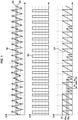
- the figure 1 comprises a first axis of abscissas illustrating the voltage Sv at the terminals of the tone wheel sensor over time, in the case of a signal altered by parasitic noise of the alternating type of frequency higher than that of the useful signal, and a second axis representing as a function of time the crenellated signal obtained S CI (without post-processing) after aliasing the voltage signal of the top graph. Since the peak-to-peak amplitude of the noise can be locally greater than the voltage difference between the restart threshold U R and the reset threshold U A , the noise causes parasitic switching of the square-wave signal.
- a third axis illustrates the variations of a signal C P for counting successive periods of the pulsed signal S CI over time.
- the time delay illustrated by the curve of this third axis is restarted here on each downward switching of the square signal, from the high level to the low level. For example, during the period P 1 illustrated in the figure, there is no parasitic switching due to noise. On the other hand, over the following period P 2 , the detected signal Sv crosses the reset threshold U A , then drops below the restart threshold U R , due to the parasitic alternating noise superimposed on the useful signal.
- the time elapsed between these two crossings of thresholds is much less than the period P 1 , which causes successive rapid switchings of the square signal S C obtained, and the detection, instead of a single theoretical period P 2 of the signal slot which would have been obtained without parasitic switching, of two successive periods P 2a and P 2b for the crenel signal S CI .
- the shaft rotation speed measurement is then disturbed.
- a common solution is to apply low-pass filtering directly to the signal before aliasing, with a cutoff frequency chosen to directly eliminate high-frequency AC noise.
- a cutoff frequency chosen to directly eliminate high-frequency AC noise.
- the elimination of a frequency noise close to the frequency of the useful signal causes a phase shift of the useful signal.
- This phase shift is problematic for certain possible uses of the speed measurement signal: in particular, the signal produced by the tone wheel can be used for the engine balancing function, if the tone wheel is configured to provide a "top per revolution" allowing to stall the motor elements on the rotation of the shaft.
- the low-pass filtering can reduce the measured amplitude of the useful signal, and increase the measurement lock-in threshold (threshold below which the rotational speed is no longer correctly measurable). This effect is all the more troublesome when the ratio between the peak-to-peak amplitude of the measurement noise and the peak-to-peak amplitude of the useful signal is high. This ratio can in particular be high when the measured speed is low, for example during an ignition phase of the engine.
- Another state-of-the-art solution consists in increasing the difference between the restart threshold and the reactivation threshold of the “trigger” to produce the crenel signal.
- this noise causes fewer parasitic switchings of the square-wave signal.
- a solution is also known consisting in adapting the amplitude of the signal before the aliasing, in order to reduce the peak-to-peak amplitude of the noise with respect to the difference between the thresholds. But again, the measurement latching threshold is increased, and the precision of the tooth passage period measurement is affected, especially as the ratio of the amplitude of the measurement noise to the amplitude of the useful signal is low.
- the invention proposes a solution for disregarding parasitic switching due to measurement noise, without however modifying either the signal to which the aliasing is applied, or the restart and reactivation thresholds of the “Schmidt trigger”.
- a principle of the present invention is to block the switchings of the crenellated signal for a certain duration after each switching, by a processing carried out downstream of the crenellation, and upstream of the measurement of the speed by the engine computer.
- the measured signal exceeds a reset threshold, or falls below a restart threshold, and the square signal is switched, said square signal is "blocked" for a duration of switching maintenance during which it is estimated that , even if the speed gradient of rotation of the teeth of the phonic wheel is at its maximum, this speed cannot reach a sufficient value to justify a new switching.
- the tone wheel of the detection unit has a singular tooth, one shape and/or one dimension differs from those of the other teeth of the phonic wheel, making it possible to identify angular points of balance.
- the invention relates to an aircraft engine comprising a rotating shaft whose rotational speed is to be measured, such as a low-pressure spool shaft whose speed N1 is to be obtained, with which is associated a detection unit conforming to the above, comprising a phonic wheel screwed around the rotating shaft, coaxial with the rotating shaft.
- An alternating signal Sv for detecting the rotational speed of the shaft of the low pressure spool (LP) of a twin spool turbojet is processed as an input to the engine computer (for example FADEC3) to obtain a raw square wave signal S CI , on which a frequency measurement, making it possible to go back to a speed value N1, can be carried out.
- the signal Sv can be filtered by an RC filter, then clipped, then filtered again, and finally crenellated by a "Schmidt trigger" with a restart threshold U R at 0 V and a rearmament threshold U A at 0.232 V.
- a first counter counts the falling edges of a high frequency sampling slot signal compared to that expected for the slot signal S C (for example 547 kHz), and a second counter counts the falling edges of the slot signal S CI , in order to determine the time period of the crenel signal S CI .
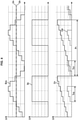
- the raw square wave signal S CI may present switchings which do not correspond to rising or falling edges for the useful part of the speed detection signal, but which are on the contrary caused by a voltage variation a parasitic alternating noise (non-useful part of the signal). This phenomenon is illustrated in picture 2 .
- a theoretical voltage Sv at the terminals of a tone wheel sensor is represented as a function of time t.
- the noisy signal Sv gives after aliasing a rising edge and a falling edge corresponding to the part 21', then a rising edge and a falling edge corresponding to the part 20', while the useful signal Su gives after aliasing a single rising edge and a single falling edge corresponding to part 20.
- the rising and falling edges of part 20' are not in correspondence with the rising and falling edges descending part 20.
- the period detection (for example the period between two successive falling edges of a crenel signal) is erroneous for the noisy signal Sv, compared to the period obtained for the useful signal Su, the latter being the measurement of interest since it is representative of the N1 regime.
- the signal processing of the following description is implemented within the engine computer (for example FADEC3).
- An algorithm is implemented within the computer, taking as input the raw pulse signal S CI obtained at the output of the “Schmidt trigger”, of the restart threshold U R and of the rearmament threshold U A .
- the algorithm is, in the following, implemented in a digital processing board, using code instructions. Alternatively, a method similar to the algorithm described below could be implemented in analog electronics.
- the algorithm delivers a processed slot signal Sc, which is more relevant with regard to the theoretical useful signal Su seen previously because it comprises little, or even no parasitic switching due to noise crossing the thresholds U A and U R of the “Schmidt trigger”.
- the frequency measurement made on the processed square wave signal S C therefore has more meaning for measuring the speed N1 than a measurement made on the raw square wave signal S CI .
- the principle of the processing method is as follows. It is assumed that the counting of the period of the crenellated signals is started at each falling edge. We are at the end of a period P n-1 (at a falling edge). Using a predetermined maximum possible speed gradient law N1, the maximum possible speed variation is calculated, and the minimum value of a quarter of the following period P n is deduced therefrom. The switching hold duration value T Hn along the period P n is taken as equal to this minimum quarter-period value obtained, and this throughout the entire period P n .
- the law used for the maximum speed gradient N1 is expressed, for example, as a function of thermodynamic parameters of the engine, or of parameters characteristic of the engine speed. This law is determined in advance, for example empirically by carrying out tests of extreme maneuvers (giving rise to high speed gradients). This law can be materialized by charts giving the maximum gradient over a plurality of engine operating points.
- the value of the previous period (expressed for example in milliseconds) is acquired for the signal Sc, and the value V n-1 of the speed of rotation of the phonic wheel corresponding to this previous period (expressed for example in rotations per minute, rpm).
- step 120 from this speed value V n-1 , and from a predetermined law G N1max of maximum gradient of speed N1 expressed as a function of the speed, a value G N1max (V n- 1 ) of maximum rotational speed gradient.
- This gradient can be expressed in rpm per second.
- step 130 the quarter of the period P n-1 is considered , multiplied by the gradient G N1max (V n-1 ) to obtain the maximum variation in speed of rotation over this quarter of the period. This maximum variation is added to the rotational speed value V n-1 for the period P n-1 , to obtain the maximum speed V nmax over a quarter of the period P n .
- a tooth passage frequency f nmax of the tone wheel is first obtained from this maximum speed value V nmax .
- V nmax is divided by 60 (to obtain a value in rotations per second), then the value obtained is multiplied by the number of teeth of the phonic wheel, to obtain the frequency f nmax of tooth passage of the tone wheel.
- P nmin we consider the inverse of the value f nmax , applying a saturation in a known way to avoid divisions by 0.
- a minimum period P nmin is therefore available for the processed square signal S C following the measured period.
- the switching hold time T Hn is finally obtained.
- This switching hold time T Hn is intended to be used as follows.
- a simplified stepped voltage signal S Vth is represented as a function of time, and is crenellated by a "Schmidt trigger" with a restart threshold U R equal to 0, and a reset threshold U A strictly positive.
- a period counting signal C P is shown superimposed, initialized at each falling edge of the crenel signal Sc, and a hold count signal switching mode C M exploiting the value T Hn of switching hold duration obtained by the algorithm detailed above.
- the time delay of the switching hold signal C M is started after each switching (on a rising edge or on a falling edge) of the square wave signal Sc.
- the period P 1 is launched on a falling edge of the signal Sc.
- the switching maintenance count signal C M is also launched on this falling edge, and elapses over a duration T H1 obtained as a function of the period P 0 above, with the algorithm illustrated by the picture 3 , then reset to 0 at the end of the duration T H1 .
- the counting of the maintenance of switching is again started, the counting of the period continuing at the same time.
- the signal S C is frozen when the value of C M is strictly greater than 0, so that the signal S C cannot switch again for the entire duration T H1 , following the switching which starts the counting of the period P 1 .
- the period P 0 is the first period observed for the signal S C (speed measurement initialization phase)
- the signal Sv returns below the restart threshold U R , due to noise.
- the switching hold counter C M being at a strictly positive value, this does not result in a switching to the low level of the square wave signal Sc.
- a parasitic switching to the low level of the square wave signal S C is avoided, during the second period T H1 of maintaining switching of the period P 1 of the signal Sc.
- the raw crenellated signal S CI is taken as input from two units 210 and 211.
- the unit 210 delivers a boolean which, at each rising edge of the signal S CI (without it being possible to distinguish the rising edges due to the useful signal and the "parasitic rising edges"), takes the value 1, and is 0 the rest of the time.
- the output of block 210 is a binary signal which identifies the instants when S CI presents a rising edge.
- Unit 211 likewise delivers a boolean which identifies the downlink signals.
- an OR logic gate delivers a signal named here TopMemo, with a value of 1 at the instants when the signal S CI switches, and with a value of 0 otherwise.
- the unit 220 takes as input, on the one hand the signal S CI , and on the other hand the signal TopMemo.
- the unit 220 also takes as input the switching hold duration value T H calculated upstream, for the current period P n .
- unit 220 includes a feedback loop: a ResetMemo signal is taken as input from 220, this signal being a function of a TopCounter signal delivered as output from 220, with the following operation.
- a value of 1 at a time t of the TopMemo signal causes, if the TopCounter counter has not already been launched, the freezing, for the processed crenel signal S C delivered at the output of 220, of the value by S CI acquired at time t, up to time t + T H , as well as the launch of the TopCounter counter.
- the signal S C no longer switches up to t+T H .
- the ResetMemo signal becomes equal to 1, and the slotted signal S C is no longer fixed at the value of S CI at time t .
- the TopCounter counter is reset to zero.
- the ResetMemo signal is therefore equal to 1 immediately after the moment when the value of the counter TopCounter exceeds T H , and 0 otherwise.
- Unit 230 makes it possible to launch a TopCounter counter, and unit 231 performs the comparison between the value of the TopCounter counter and the value T H . This value is then delayed by a delay operator 232 to provide a feedback ResetMemo signal.
- a value of 1 of the ResetMemo signal causes counter TopCounter to be reset to zero if its value is greater than T H , allowing the counter TopCounter to be started again on the next switching of S CI .
- the figure 7 schematically represents a turbomachine 1 comprising a rotating shaft 10 of the low-pressure body whose rotation speed N1 is to be determined.
- the motor 1 comprises a unit for detecting the rotational speed of the shaft 10.
- the detection unit comprises a phonic wheel 11, screwed around the shaft 10 coaxially with the shaft 10.
- the phonic wheel 11 is driven in rotation by the shaft 10, and has a plurality of regularly spaced teeth.
- the wheel 11 comprises a singular tooth 12 different from the other teeth.
- the detection unit further comprises a variable reluctance sensor 13, placed in the vicinity of the wheel 11, so that the passage of the teeth of the wheel 11 generates an alternating rotation speed detection signal.
- the frequency of the detection signal thus generated is proportional to the speed of rotation of the shaft.
- the figure 7 further represents, associated with the variable reluctance sensor 13, an electronic circuit 14 of the detection unit, comprising a connection with the sensor 13 to receive the rotation speed detection signal, and to perform the aliasing of said signal to give a raw crenel signal.
- the raw square-wave signal thus produced by circuit 14 may include spurious switching due to noise.
- the detection unit further comprises a processing unit 15 comprising calculation means, for example a processor.
- the processing unit 15 is configured to implement the method represented in picture 3 , to produce a processed slot signal.
- a rotation speed detection unit can be associated with a rotating shaft of motor 1 other than a shaft of the low pressure body.
- the processing method described above provides, on the basis of a law of maximum engine speed gradient, a simple solution for greatly reducing and in real time the influence of parasitic noises (in particular noises of the alternating type, coming from overlap in an unpredictable way useful signal) on the engine speed measurement.
- This solution requiring neither a decrease in the peak-to-peak amplitude of the useful signal, nor an increase in the voltage difference between the restart threshold and the rearming threshold of the "Schmidt trigger" performing the aliasing, it alters the accuracy and measurement sensitivity than solutions known from the state of the art.
Landscapes
- Physics & Mathematics (AREA)
- General Physics & Mathematics (AREA)
- Engineering & Computer Science (AREA)
- Chemical & Material Sciences (AREA)
- Combustion & Propulsion (AREA)
- Mechanical Engineering (AREA)
- General Engineering & Computer Science (AREA)
- Measurement Of Mechanical Vibrations Or Ultrasonic Waves (AREA)
- Transmission And Conversion Of Sensor Element Output (AREA)
- Combined Controls Of Internal Combustion Engines (AREA)
Claims (8)
- Verfahren zur Verarbeitung eines Drehzahldetektions-Wechselsignals (SV) einer Welle eines Luftfahrzeugmotors, das durch einen Sensor mit variabler Reluktanz erzeugt wird und von Messstörrauschen beeinträchtigt wird, ausgehend von einem Rohrechtecksignal (SCI), das entsprechend dem Übergang der Spannung des Wechselsignals (SV) unter eine Neustartsschwelle (UR) beziehungsweise über eine Wiederaufrüstungsschwelle (UA) hin zu einem niedrigen Spannungspegel (U1) beziehungsweise hin zu einem hohen Spannungspegel (U2) schaltet, wobei das Verfahren die folgenden Schritte umfasst:- Berechnen eines verarbeiteten Rechtecksignals (SC) ausgehend von dem Rohrechtecksignal (SCI) und mittels eines Schaltaufrechterhaltungsdauerwerts (TH) unterhalb dessen ein Teil ohne Rauschen des Wechselsignals (SV) kein Schalten verursacht,
wobei die Schaltaufrechterhaltungsdauer (TH) in Abhängigkeit von einem Drehzahlwert der Welle, der für die vorhergehende Periode (Pn-1) des verarbeiteten Rechtecksignals (SC) erhalten wird, mittels eines vorbestimmten Gesetzes des maximalen Gradienten berechnet wird, das einen maximalen Drehzahlgradienten (GN1max) der Welle in Abhängigkeit von dem Wert der Drehzahl der Welle für die vorhergehende Periode (Pn-1) ausdrückt,- Messung der Drehzahl der Welle durch Frequenzmessung des verarbeiteten Rechtecksignals (SC),wobei jede Schaltung hin zum niedrigen Pegel (U1) oder hin zum hohen Pegel (U2) des verarbeiteten Rechtecksignals (SC) das Feststehen des verarbeiteten Rechtecksignals (SC) während einer Dauer auslöst, die genau gleich der vorhergehend berechneten Schaltaufrechterhaltungsdauer (TH) ist, derart dass die Schaltungen des Rohrechtecksignals (SCI) während des Feststehens keine Schaltungen des verarbeiteten Rechtecksignals (SC) umsetzen,wobei das verarbeitete Rechtecksignal (SC) nicht mehr feststeht, nachdem die Schaltaufrechterhaltungsdauer (TH) verstrichen ist. - Verfahren nach Anspruch 1, wobei der Schaltaufrechterhaltungsdauerwert (TH) einem Viertel einer Mindestdrehperiode der Welle am Zeitpunkt der Messung entspricht.
- Verfahren nach einem beliebigen der Ansprüche 1 oder 2, wobei das Drehzahldetektionswechselsignal (SV) durch einen "Schmitt-Trigger" in ein Rechtecksignal umgewandelt wird.
- Verfahren nach einem beliebigen der Ansprüche 1 bis 3, wobei während einer Drehzahlmessungsinitialisierungsphase ein theoretisches Modell der Motordrehzahl zum Bewerten der Schaltaufrechterhaltungsdauer (TH) verwendet wird.
- Verfahren nach Anspruch 4, wobei die anfängliche Schaltaufrechterhaltungsdauer (TH0) mittels des theoretischen Modells der Motordrehzahl in Abhängigkeit von Betriebsbedingungen und einer Bemessung des Luftfahrzeugmotors erhalten wird und zum Berechnen des verarbeiteten Rechtecksignals (SC) während der Initialisierungsphase der Drehzahlmessung verwendet wird.
- Einheit zur Detektion der Drehzahl einer Luftfahrzeugmotorwelle, die umfasst:- ein phonisches Rad, das durch die Welle drehbar angetrieben wird und eine Vielzahl von gleichmäßig beabstandeten Zähnen aufweist,- einen Sensor mit variabler Reluktanz, der in der Nachbarschaft des phonischen Rades platziert ist, derart dass das Passieren der Zähne des phonischen Rades ein Drehzahldetektionswechselsignal erzeugt, wobei eine Frequenz des Wechselsignals proportional zur Drehzahl der Welle ist,- eine elektronische Schaltung, die die Rechteckumwandlung des Wechselsignals (SV) in ein Rohrechtecksignal (SCI) ausführt,- eine Verarbeitungseinheit, die geeignet ist, ein Verfahren nach einem der Ansprüche 1 bis 5 durchzuführen, um am Ausgang ein verarbeitetes Rechtecksignal (SC) zu liefern.
- Detektionseinheit nach Anspruch 6, wobei das phonische Rad einen singulären Zahn umfasst und ferner eine Vielzahl von anderen Zähne umfasst, wobei eine Form und/oder eine Abmessung des singulären Zahnes sich von denjenigen der anderen Zähne unterscheidet, wodurch die Feststellung der Ausgleichswinkelpunkte ermöglicht wird.
- Luftfahrzeugmotor, der umfasst:- eine Drehwelle,- eine Detektionseinheit nach einem der Ansprüche 6 oder 7, die ein phonisches Rad umfasst, das um die Welle herum koaxial zu der Welle geschraubt ist.
Applications Claiming Priority (1)
| Application Number | Priority Date | Filing Date | Title |
|---|---|---|---|
| FR1755340A FR3067888B1 (fr) | 2017-06-14 | 2017-06-14 | Procede de traitement d'un signal de vitesse de rotation d'un arbre de moteur d'aeronef affecte par du bruit |
Publications (2)
| Publication Number | Publication Date |
|---|---|
| EP3418753A1 EP3418753A1 (de) | 2018-12-26 |
| EP3418753B1 true EP3418753B1 (de) | 2022-01-26 |
Family
ID=59746097
Family Applications (1)
| Application Number | Title | Priority Date | Filing Date |
|---|---|---|---|
| EP18177655.0A Active EP3418753B1 (de) | 2017-06-14 | 2018-06-14 | Verarbeitungsverfahren eines durch rauschen gestörten signals der motorwellen-drehgeschwindigkeit eines luftfahrzeugs |
Country Status (3)
| Country | Link |
|---|---|
| US (1) | US10830786B2 (de) |
| EP (1) | EP3418753B1 (de) |
| FR (1) | FR3067888B1 (de) |
Families Citing this family (5)
| Publication number | Priority date | Publication date | Assignee | Title |
|---|---|---|---|---|
| US11168612B2 (en) | 2018-09-21 | 2021-11-09 | Pratt & Whitney Canada Corp. | Signal processing for variable geometry mechanism control |
| US11592455B2 (en) * | 2020-01-13 | 2023-02-28 | Woodward, Inc. | Adaptive voltage threshold for turbine engine |
| CN112433064A (zh) * | 2020-11-06 | 2021-03-02 | 杭州和利时自动化有限公司 | 一种转速检测方法、装置及设备 |
| CN115856344B (zh) * | 2022-12-26 | 2025-06-27 | 东风商用车有限公司 | 一种发动机转速信号识别方法、装置、设备及存储介质 |
| CN119780461B (zh) * | 2024-11-29 | 2026-01-16 | 中国航发西安动力控制科技有限公司 | 一种航空发动机转速测量装置 |
Family Cites Families (8)
| Publication number | Priority date | Publication date | Assignee | Title |
|---|---|---|---|---|
| US4287480A (en) * | 1980-01-10 | 1981-09-01 | Sperry Corporation | Phase locked loop out-of-lock detector |
| JPS59180463A (ja) * | 1983-03-31 | 1984-10-13 | Fujitsu Ten Ltd | エンジン回転数読取り方式 |
| JPS60225067A (ja) * | 1984-04-24 | 1985-11-09 | Fujitsu Ten Ltd | 車速検出方法 |
| JPS60225066A (ja) * | 1984-04-24 | 1985-11-09 | Fujitsu Ten Ltd | 車速検出方法 |
| DE3911830A1 (de) * | 1989-04-11 | 1990-10-18 | Bosch Gmbh Robert | Verfahren und schaltung zur auswertung von kontinuierlich auftretenden zeitmarken |
| KR100346838B1 (ko) * | 2000-09-21 | 2002-08-03 | 삼성전자 주식회사 | Pll 락 검출기회로 및 락 검출방법 |
| FR2888687B1 (fr) * | 2005-07-13 | 2007-10-12 | Siemens Vdo Automotive Sas | Dispositif de filtrage d'un signal et procede correspondant |
| JP2007121216A (ja) * | 2005-10-31 | 2007-05-17 | Aisin Seiki Co Ltd | 回転状態検出装置 |
-
2017
- 2017-06-14 FR FR1755340A patent/FR3067888B1/fr active Active
-
2018
- 2018-06-12 US US16/006,199 patent/US10830786B2/en active Active
- 2018-06-14 EP EP18177655.0A patent/EP3418753B1/de active Active
Non-Patent Citations (1)
| Title |
|---|
| None * |
Also Published As
| Publication number | Publication date |
|---|---|
| US20180364271A1 (en) | 2018-12-20 |
| FR3067888B1 (fr) | 2019-06-28 |
| US10830786B2 (en) | 2020-11-10 |
| EP3418753A1 (de) | 2018-12-26 |
| FR3067888A1 (fr) | 2018-12-21 |
Similar Documents
| Publication | Publication Date | Title |
|---|---|---|
| EP3418753A1 (de) | Verarbeitungsverfahren eines durch rauschen gestörten signals der motorwellen-drehgeschwindigkeit eines luftfahrzeugs | |
| WO2016165829A1 (fr) | Procede et dispositif de detection de rotation inverse d'un moteur a combustion interne | |
| EP3639041B1 (de) | Verfahren zur messung der drehzahl einer flugzeugmotorwelle unter berücksichtigung des messrauschens | |
| EP3752811B1 (de) | Verfahren und system zur erkennung von schäden an den beweglichen schaufeln eines flugzeuges | |
| FR2890690A1 (fr) | Procede de determination de l'inversion du sens de rotation d'un moteur | |
| FR2978542A1 (fr) | Procede de determination d'une information representative de la position d'une dent reelle d'une cible dentee solidaire en rotation d'un arbre d'un moteur a combustion interne et dispositif associe | |
| EP4182215B1 (de) | Sensorlose erkennung echter pedalkraft | |
| FR2591752A1 (fr) | Systeme de mesure de vitesse et de phase pour des helices d'aeronef | |
| FR3014139A1 (fr) | Procede de determination de la position angulaire instantanee d'une cible vilebrequin | |
| EP3578929B1 (de) | Verfahren und system zur bestimmung der winkelposition der laufradschaufeln eines schaufelrads eines turbotriebwerks | |
| EP2972114B1 (de) | Kalibrierverfahren eines positionssensors in einer elektrischen synchronmaschine | |
| FR3154802A1 (fr) | Procédé de détermination d’une information de mouvement d’un véhicule, dispositif capteur, programme informatique, support lisible par ordinateur, et véhicule correspondants | |
| EP1595066A1 (de) | Verfahren zur erfassung des verbrennungsversagens durch filtern | |
| WO2020064734A1 (fr) | Procédé de détermination de la position d'un vilebrequin de véhicule automobile | |
| FR3107367A1 (fr) | Mesure de fonction de transferts dans un système mécatronique | |
| EP3722891B1 (de) | Verfahren und system zur bestimmung eines fehlers und der korrektur der winkelposition eines kontinuierlich drehenden motors | |
| EP1936169A2 (de) | Verfahren zur Bestimmung der Laufzeit der Zähne einer Welle einer Brennkraftmaschine | |
| FR2988834A1 (fr) | Methode d'interpolation de signal evenementiel | |
| FR3077881A1 (fr) | Procede et systeme de detection d'un endommagement d'aubes mobiles d'un aeronef | |
| FR2678369A1 (fr) | Dispositif de commande d'un indicateur electrique a bobines croisees, de type logometre. |
Legal Events
| Date | Code | Title | Description |
|---|---|---|---|
| PUAI | Public reference made under article 153(3) epc to a published international application that has entered the european phase |
Free format text: ORIGINAL CODE: 0009012 |
|
| STAA | Information on the status of an ep patent application or granted ep patent |
Free format text: STATUS: THE APPLICATION HAS BEEN PUBLISHED |
|
| AK | Designated contracting states |
Kind code of ref document: A1 Designated state(s): AL AT BE BG CH CY CZ DE DK EE ES FI FR GB GR HR HU IE IS IT LI LT LU LV MC MK MT NL NO PL PT RO RS SE SI SK SM TR |
|
| AX | Request for extension of the european patent |
Extension state: BA ME |
|
| STAA | Information on the status of an ep patent application or granted ep patent |
Free format text: STATUS: REQUEST FOR EXAMINATION WAS MADE |
|
| 17P | Request for examination filed |
Effective date: 20190430 |
|
| RBV | Designated contracting states (corrected) |
Designated state(s): AL AT BE BG CH CY CZ DE DK EE ES FI FR GB GR HR HU IE IS IT LI LT LU LV MC MK MT NL NO PL PT RO RS SE SI SK SM TR |
|
| STAA | Information on the status of an ep patent application or granted ep patent |
Free format text: STATUS: EXAMINATION IS IN PROGRESS |
|
| 17Q | First examination report despatched |
Effective date: 20200527 |
|
| GRAP | Despatch of communication of intention to grant a patent |
Free format text: ORIGINAL CODE: EPIDOSNIGR1 |
|
| STAA | Information on the status of an ep patent application or granted ep patent |
Free format text: STATUS: GRANT OF PATENT IS INTENDED |
|
| INTG | Intention to grant announced |
Effective date: 20211005 |
|
| GRAS | Grant fee paid |
Free format text: ORIGINAL CODE: EPIDOSNIGR3 |
|
| GRAA | (expected) grant |
Free format text: ORIGINAL CODE: 0009210 |
|
| STAA | Information on the status of an ep patent application or granted ep patent |
Free format text: STATUS: THE PATENT HAS BEEN GRANTED |
|
| AK | Designated contracting states |
Kind code of ref document: B1 Designated state(s): AL AT BE BG CH CY CZ DE DK EE ES FI FR GB GR HR HU IE IS IT LI LT LU LV MC MK MT NL NO PL PT RO RS SE SI SK SM TR |
|
| REG | Reference to a national code |
Ref country code: GB Ref legal event code: FG4D Free format text: NOT ENGLISH |
|
| REG | Reference to a national code |
Ref country code: CH Ref legal event code: EP |
|
| REG | Reference to a national code |
Ref country code: AT Ref legal event code: REF Ref document number: 1465681 Country of ref document: AT Kind code of ref document: T Effective date: 20220215 |
|
| REG | Reference to a national code |
Ref country code: IE Ref legal event code: FG4D Free format text: LANGUAGE OF EP DOCUMENT: FRENCH |
|
| REG | Reference to a national code |
Ref country code: DE Ref legal event code: R096 Ref document number: 602018029961 Country of ref document: DE |
|
| REG | Reference to a national code |
Ref country code: LT Ref legal event code: MG9D |
|
| REG | Reference to a national code |
Ref country code: NL Ref legal event code: MP Effective date: 20220126 |
|
| REG | Reference to a national code |
Ref country code: AT Ref legal event code: MK05 Ref document number: 1465681 Country of ref document: AT Kind code of ref document: T Effective date: 20220126 |
|
| PG25 | Lapsed in a contracting state [announced via postgrant information from national office to epo] |
Ref country code: NL Free format text: LAPSE BECAUSE OF FAILURE TO SUBMIT A TRANSLATION OF THE DESCRIPTION OR TO PAY THE FEE WITHIN THE PRESCRIBED TIME-LIMIT Effective date: 20220126 |
|
| PG25 | Lapsed in a contracting state [announced via postgrant information from national office to epo] |
Ref country code: SE Free format text: LAPSE BECAUSE OF FAILURE TO SUBMIT A TRANSLATION OF THE DESCRIPTION OR TO PAY THE FEE WITHIN THE PRESCRIBED TIME-LIMIT Effective date: 20220126 Ref country code: RS Free format text: LAPSE BECAUSE OF FAILURE TO SUBMIT A TRANSLATION OF THE DESCRIPTION OR TO PAY THE FEE WITHIN THE PRESCRIBED TIME-LIMIT Effective date: 20220126 Ref country code: PT Free format text: LAPSE BECAUSE OF FAILURE TO SUBMIT A TRANSLATION OF THE DESCRIPTION OR TO PAY THE FEE WITHIN THE PRESCRIBED TIME-LIMIT Effective date: 20220526 Ref country code: NO Free format text: LAPSE BECAUSE OF FAILURE TO SUBMIT A TRANSLATION OF THE DESCRIPTION OR TO PAY THE FEE WITHIN THE PRESCRIBED TIME-LIMIT Effective date: 20220426 Ref country code: LT Free format text: LAPSE BECAUSE OF FAILURE TO SUBMIT A TRANSLATION OF THE DESCRIPTION OR TO PAY THE FEE WITHIN THE PRESCRIBED TIME-LIMIT Effective date: 20220126 Ref country code: HR Free format text: LAPSE BECAUSE OF FAILURE TO SUBMIT A TRANSLATION OF THE DESCRIPTION OR TO PAY THE FEE WITHIN THE PRESCRIBED TIME-LIMIT Effective date: 20220126 Ref country code: ES Free format text: LAPSE BECAUSE OF FAILURE TO SUBMIT A TRANSLATION OF THE DESCRIPTION OR TO PAY THE FEE WITHIN THE PRESCRIBED TIME-LIMIT Effective date: 20220126 Ref country code: BG Free format text: LAPSE BECAUSE OF FAILURE TO SUBMIT A TRANSLATION OF THE DESCRIPTION OR TO PAY THE FEE WITHIN THE PRESCRIBED TIME-LIMIT Effective date: 20220426 |
|
| PG25 | Lapsed in a contracting state [announced via postgrant information from national office to epo] |
Ref country code: PL Free format text: LAPSE BECAUSE OF FAILURE TO SUBMIT A TRANSLATION OF THE DESCRIPTION OR TO PAY THE FEE WITHIN THE PRESCRIBED TIME-LIMIT Effective date: 20220126 Ref country code: LV Free format text: LAPSE BECAUSE OF FAILURE TO SUBMIT A TRANSLATION OF THE DESCRIPTION OR TO PAY THE FEE WITHIN THE PRESCRIBED TIME-LIMIT Effective date: 20220126 Ref country code: GR Free format text: LAPSE BECAUSE OF FAILURE TO SUBMIT A TRANSLATION OF THE DESCRIPTION OR TO PAY THE FEE WITHIN THE PRESCRIBED TIME-LIMIT Effective date: 20220427 Ref country code: FI Free format text: LAPSE BECAUSE OF FAILURE TO SUBMIT A TRANSLATION OF THE DESCRIPTION OR TO PAY THE FEE WITHIN THE PRESCRIBED TIME-LIMIT Effective date: 20220126 Ref country code: AT Free format text: LAPSE BECAUSE OF FAILURE TO SUBMIT A TRANSLATION OF THE DESCRIPTION OR TO PAY THE FEE WITHIN THE PRESCRIBED TIME-LIMIT Effective date: 20220126 |
|
| PG25 | Lapsed in a contracting state [announced via postgrant information from national office to epo] |
Ref country code: IS Free format text: LAPSE BECAUSE OF FAILURE TO SUBMIT A TRANSLATION OF THE DESCRIPTION OR TO PAY THE FEE WITHIN THE PRESCRIBED TIME-LIMIT Effective date: 20220526 |
|
| REG | Reference to a national code |
Ref country code: DE Ref legal event code: R097 Ref document number: 602018029961 Country of ref document: DE |
|
| PG25 | Lapsed in a contracting state [announced via postgrant information from national office to epo] |
Ref country code: SM Free format text: LAPSE BECAUSE OF FAILURE TO SUBMIT A TRANSLATION OF THE DESCRIPTION OR TO PAY THE FEE WITHIN THE PRESCRIBED TIME-LIMIT Effective date: 20220126 Ref country code: SK Free format text: LAPSE BECAUSE OF FAILURE TO SUBMIT A TRANSLATION OF THE DESCRIPTION OR TO PAY THE FEE WITHIN THE PRESCRIBED TIME-LIMIT Effective date: 20220126 Ref country code: RO Free format text: LAPSE BECAUSE OF FAILURE TO SUBMIT A TRANSLATION OF THE DESCRIPTION OR TO PAY THE FEE WITHIN THE PRESCRIBED TIME-LIMIT Effective date: 20220126 Ref country code: EE Free format text: LAPSE BECAUSE OF FAILURE TO SUBMIT A TRANSLATION OF THE DESCRIPTION OR TO PAY THE FEE WITHIN THE PRESCRIBED TIME-LIMIT Effective date: 20220126 Ref country code: DK Free format text: LAPSE BECAUSE OF FAILURE TO SUBMIT A TRANSLATION OF THE DESCRIPTION OR TO PAY THE FEE WITHIN THE PRESCRIBED TIME-LIMIT Effective date: 20220126 Ref country code: CZ Free format text: LAPSE BECAUSE OF FAILURE TO SUBMIT A TRANSLATION OF THE DESCRIPTION OR TO PAY THE FEE WITHIN THE PRESCRIBED TIME-LIMIT Effective date: 20220126 |
|
| PG25 | Lapsed in a contracting state [announced via postgrant information from national office to epo] |
Ref country code: AL Free format text: LAPSE BECAUSE OF FAILURE TO SUBMIT A TRANSLATION OF THE DESCRIPTION OR TO PAY THE FEE WITHIN THE PRESCRIBED TIME-LIMIT Effective date: 20220126 |
|
| PLBE | No opposition filed within time limit |
Free format text: ORIGINAL CODE: 0009261 |
|
| STAA | Information on the status of an ep patent application or granted ep patent |
Free format text: STATUS: NO OPPOSITION FILED WITHIN TIME LIMIT |
|
| 26N | No opposition filed |
Effective date: 20221027 |
|
| PG25 | Lapsed in a contracting state [announced via postgrant information from national office to epo] |
Ref country code: MC Free format text: LAPSE BECAUSE OF FAILURE TO SUBMIT A TRANSLATION OF THE DESCRIPTION OR TO PAY THE FEE WITHIN THE PRESCRIBED TIME-LIMIT Effective date: 20220126 |
|
| REG | Reference to a national code |
Ref country code: CH Ref legal event code: PL |
|
| REG | Reference to a national code |
Ref country code: BE Ref legal event code: MM Effective date: 20220630 |
|
| PG25 | Lapsed in a contracting state [announced via postgrant information from national office to epo] |
Ref country code: SI Free format text: LAPSE BECAUSE OF FAILURE TO SUBMIT A TRANSLATION OF THE DESCRIPTION OR TO PAY THE FEE WITHIN THE PRESCRIBED TIME-LIMIT Effective date: 20220126 |
|
| PG25 | Lapsed in a contracting state [announced via postgrant information from national office to epo] |
Ref country code: LU Free format text: LAPSE BECAUSE OF NON-PAYMENT OF DUE FEES Effective date: 20220614 Ref country code: LI Free format text: LAPSE BECAUSE OF NON-PAYMENT OF DUE FEES Effective date: 20220630 Ref country code: IE Free format text: LAPSE BECAUSE OF NON-PAYMENT OF DUE FEES Effective date: 20220614 Ref country code: CH Free format text: LAPSE BECAUSE OF NON-PAYMENT OF DUE FEES Effective date: 20220630 |
|
| PG25 | Lapsed in a contracting state [announced via postgrant information from national office to epo] |
Ref country code: BE Free format text: LAPSE BECAUSE OF NON-PAYMENT OF DUE FEES Effective date: 20220630 |
|
| PG25 | Lapsed in a contracting state [announced via postgrant information from national office to epo] |
Ref country code: IT Free format text: LAPSE BECAUSE OF FAILURE TO SUBMIT A TRANSLATION OF THE DESCRIPTION OR TO PAY THE FEE WITHIN THE PRESCRIBED TIME-LIMIT Effective date: 20220126 |
|
| PG25 | Lapsed in a contracting state [announced via postgrant information from national office to epo] |
Ref country code: HU Free format text: LAPSE BECAUSE OF FAILURE TO SUBMIT A TRANSLATION OF THE DESCRIPTION OR TO PAY THE FEE WITHIN THE PRESCRIBED TIME-LIMIT; INVALID AB INITIO Effective date: 20180614 |
|
| PG25 | Lapsed in a contracting state [announced via postgrant information from national office to epo] |
Ref country code: MK Free format text: LAPSE BECAUSE OF FAILURE TO SUBMIT A TRANSLATION OF THE DESCRIPTION OR TO PAY THE FEE WITHIN THE PRESCRIBED TIME-LIMIT Effective date: 20220126 Ref country code: CY Free format text: LAPSE BECAUSE OF FAILURE TO SUBMIT A TRANSLATION OF THE DESCRIPTION OR TO PAY THE FEE WITHIN THE PRESCRIBED TIME-LIMIT Effective date: 20220126 |
|
| PG25 | Lapsed in a contracting state [announced via postgrant information from national office to epo] |
Ref country code: TR Free format text: LAPSE BECAUSE OF FAILURE TO SUBMIT A TRANSLATION OF THE DESCRIPTION OR TO PAY THE FEE WITHIN THE PRESCRIBED TIME-LIMIT Effective date: 20220126 |
|
| PG25 | Lapsed in a contracting state [announced via postgrant information from national office to epo] |
Ref country code: MT Free format text: LAPSE BECAUSE OF FAILURE TO SUBMIT A TRANSLATION OF THE DESCRIPTION OR TO PAY THE FEE WITHIN THE PRESCRIBED TIME-LIMIT Effective date: 20220126 |
|
| PGFP | Annual fee paid to national office [announced via postgrant information from national office to epo] |
Ref country code: DE Payment date: 20250618 Year of fee payment: 8 |
|
| PGFP | Annual fee paid to national office [announced via postgrant information from national office to epo] |
Ref country code: GB Payment date: 20250625 Year of fee payment: 8 |
|
| PGFP | Annual fee paid to national office [announced via postgrant information from national office to epo] |
Ref country code: FR Payment date: 20250620 Year of fee payment: 8 |