EP3418683B1 - Koordinatenmesseinheit und verfahren zur erkennung einer messsonde - Google Patents
Koordinatenmesseinheit und verfahren zur erkennung einer messsonde Download PDFInfo
- Publication number
- EP3418683B1 EP3418683B1 EP18179009.8A EP18179009A EP3418683B1 EP 3418683 B1 EP3418683 B1 EP 3418683B1 EP 18179009 A EP18179009 A EP 18179009A EP 3418683 B1 EP3418683 B1 EP 3418683B1
- Authority
- EP
- European Patent Office
- Prior art keywords
- identification code
- probe
- measuring probe
- measuring
- unit
- Prior art date
- Legal status (The legal status is an assumption and is not a legal conclusion. Google has not performed a legal analysis and makes no representation as to the accuracy of the status listed.)
- Active
Links
Images



Classifications
-
- G—PHYSICS
- G01—MEASURING; TESTING
- G01B—MEASURING LENGTH, THICKNESS OR SIMILAR LINEAR DIMENSIONS; MEASURING ANGLES; MEASURING AREAS; MEASURING IRREGULARITIES OF SURFACES OR CONTOURS
- G01B21/00—Measuring arrangements or details thereof, where the measuring technique is not covered by the other groups of this subclass, unspecified or not relevant
-
- G—PHYSICS
- G01—MEASURING; TESTING
- G01B—MEASURING LENGTH, THICKNESS OR SIMILAR LINEAR DIMENSIONS; MEASURING ANGLES; MEASURING AREAS; MEASURING IRREGULARITIES OF SURFACES OR CONTOURS
- G01B11/00—Measuring arrangements characterised by the use of optical techniques
- G01B11/002—Measuring arrangements characterised by the use of optical techniques for measuring two or more coordinates
- G01B11/005—Measuring arrangements characterised by the use of optical techniques for measuring two or more coordinates coordinate measuring machines
-
- G—PHYSICS
- G01—MEASURING; TESTING
- G01B—MEASURING LENGTH, THICKNESS OR SIMILAR LINEAR DIMENSIONS; MEASURING ANGLES; MEASURING AREAS; MEASURING IRREGULARITIES OF SURFACES OR CONTOURS
- G01B21/00—Measuring arrangements or details thereof, where the measuring technique is not covered by the other groups of this subclass, unspecified or not relevant
- G01B21/02—Measuring arrangements or details thereof, where the measuring technique is not covered by the other groups of this subclass, unspecified or not relevant for measuring length, width, or thickness
- G01B21/04—Measuring arrangements or details thereof, where the measuring technique is not covered by the other groups of this subclass, unspecified or not relevant for measuring length, width, or thickness by measuring coordinates of points
- G01B21/047—Accessories, e.g. for positioning, for tool-setting, for measuring probes
-
- G—PHYSICS
- G01—MEASURING; TESTING
- G01B—MEASURING LENGTH, THICKNESS OR SIMILAR LINEAR DIMENSIONS; MEASURING ANGLES; MEASURING AREAS; MEASURING IRREGULARITIES OF SURFACES OR CONTOURS
- G01B21/00—Measuring arrangements or details thereof, where the measuring technique is not covered by the other groups of this subclass, unspecified or not relevant
- G01B21/02—Measuring arrangements or details thereof, where the measuring technique is not covered by the other groups of this subclass, unspecified or not relevant for measuring length, width, or thickness
- G01B21/04—Measuring arrangements or details thereof, where the measuring technique is not covered by the other groups of this subclass, unspecified or not relevant for measuring length, width, or thickness by measuring coordinates of points
- G01B21/042—Calibration or calibration artifacts
-
- G—PHYSICS
- G01—MEASURING; TESTING
- G01B—MEASURING LENGTH, THICKNESS OR SIMILAR LINEAR DIMENSIONS; MEASURING ANGLES; MEASURING AREAS; MEASURING IRREGULARITIES OF SURFACES OR CONTOURS
- G01B21/00—Measuring arrangements or details thereof, where the measuring technique is not covered by the other groups of this subclass, unspecified or not relevant
- G01B21/20—Measuring arrangements or details thereof, where the measuring technique is not covered by the other groups of this subclass, unspecified or not relevant for measuring contours or curvatures, e.g. determining profile
-
- G—PHYSICS
- G01—MEASURING; TESTING
- G01B—MEASURING LENGTH, THICKNESS OR SIMILAR LINEAR DIMENSIONS; MEASURING ANGLES; MEASURING AREAS; MEASURING IRREGULARITIES OF SURFACES OR CONTOURS
- G01B5/00—Measuring arrangements characterised by the use of mechanical techniques
- G01B5/004—Measuring arrangements characterised by the use of mechanical techniques for measuring coordinates of points
- G01B5/008—Measuring arrangements characterised by the use of mechanical techniques for measuring coordinates of points using coordinate measuring machines
-
- G—PHYSICS
- G01—MEASURING; TESTING
- G01B—MEASURING LENGTH, THICKNESS OR SIMILAR LINEAR DIMENSIONS; MEASURING ANGLES; MEASURING AREAS; MEASURING IRREGULARITIES OF SURFACES OR CONTOURS
- G01B7/00—Measuring arrangements characterised by the use of electric or magnetic techniques
- G01B7/004—Measuring arrangements characterised by the use of electric or magnetic techniques for measuring coordinates of points
- G01B7/008—Measuring arrangements characterised by the use of electric or magnetic techniques for measuring coordinates of points using coordinate measuring machines
-
- G—PHYSICS
- G06—COMPUTING OR CALCULATING; COUNTING
- G06F—ELECTRIC DIGITAL DATA PROCESSING
- G06F21/00—Security arrangements for protecting computers, components thereof, programs or data against unauthorised activity
- G06F21/70—Protecting specific internal or peripheral components, in which the protection of a component leads to protection of the entire computer
- G06F21/71—Protecting specific internal or peripheral components, in which the protection of a component leads to protection of the entire computer to assure secure computing or processing of information
- G06F21/73—Protecting specific internal or peripheral components, in which the protection of a component leads to protection of the entire computer to assure secure computing or processing of information by creating or determining hardware identification, e.g. serial numbers
-
- G—PHYSICS
- G01—MEASURING; TESTING
- G01B—MEASURING LENGTH, THICKNESS OR SIMILAR LINEAR DIMENSIONS; MEASURING ANGLES; MEASURING AREAS; MEASURING IRREGULARITIES OF SURFACES OR CONTOURS
- G01B2210/00—Aspects not specifically covered by any group under G01B, e.g. of wheel alignment, caliper-like sensors
- G01B2210/60—Unique sensor identification
Definitions
- the present invention relates to a coordinate measuring unit and a method for recognizing a measuring probe, and particularly, to a coordinate measuring unit and a method for recognizing a measuring probe which enable efficient recognition of a number of measuring probes.
- the measuring probe for detecting the surface shape of an object to be measured is connected not only to the main body of a coordinate measuring machine but also, for example, to the main body of a machine tool, so as to function as a unit for measuring the three-dimensional shape of the object to be measured (referred to as the coordinate measuring unit).
- the measuring probe attached to each main body is first identified by a processing device connected to each main body. After that, the measuring probe is to detect the surface shape of the object to be measured.
- the measuring probe conventionally includes a resistor having a resistance value specific to the type of each measuring probe, and the type of the measuring probe is recognized by measuring the resistance value.
- the resistor is supplied with a current from a constant-current source, and the potential difference produced across the resistor is measured to thereby measure the resistance value and identify, from the resistance value, which type the measuring probe belongs to. That is, the measuring probe including a resistor enables the measuring probe to be recognized in a very simplified manner.
- the resistance values of respective resistors and the circuits for detecting the resistance values actually have errors, and the number of resistors that can be assigned to each practical measuring probe is limited. Furthermore, the resistance value assigned to a conventional measuring probe cannot be reassigned to a new measuring probe unless the conventional measuring probe is completely unavailable. That is, there was a possibility that the conventional method by assigning resistance values was applied to a number of new measuring probes with difficulty.
- the present invention has been made to solve the conventional problems mentioned above, and it is therefore an object of the present invention to provide a coordinate measuring unit capable of efficiently recognizing a number of measuring probes and a method for recognizing the measuring probes.
- the coordinate measuring machine 100 includes a measuring probe 300, a coordinate measuring machine main body 200 configured to move the measuring probe 300, an operation unit 110 having a joystick 111 configured to perform manual operation, and a processing device 400 configured to compute the shape coordinates of an object to be measured W on the basis of an output from the measuring probe 300.
- the coordinate measuring machine main body 200 includes a surface plate 210, a drive mechanism 220, and the measuring probe 300 (301).
- the drive mechanism 220 includes an X-axis drive mechanism, a Y-axis drive mechanism, and a Z-axis drive mechanism (none of which are illustrated) which are erected on the surface plate 210 so as to hold and three-dimensionally move the measuring probe 300 (301).
- the drive mechanism 220 includes beam supports 221 movable in the Ym direction of a machine coordinate system, a beam 222 bridged between the beam supports 221, a column 223 movable in the Xm direction of the machine coordinate system on the beam 222, and a spindle 224 movable in the Zm direction of the machine coordinate system in the column 223.
- the X-axis drive mechanism, the Y-axis drive mechanism, and the Z-axis drive mechanism are provided between the beam 222 and the column 223, between the surface plate 210 and the beam supports 221, and between the column 223 and the spindle 224, respectively.
- a probe head 225 is provided at an end of the spindle 224, and the measuring probe 300 (301) is supported on the end.
- the measuring probe 300 is a so-called scanning probe configured to trace the surface of the object to be measured W.
- the measuring probe 300 includes a probe main body 302, and a stylus module 304 movably supported by the probe main body 302.
- the stylus module 304 is connected to the probe main body 302 via a flange 304A and supports a stem 304B, and includes, at an end of the stem 304B, a spherical contact part 304C that is brought into contact with the object to be measured W in order to detect the object to be measured W.
- the stylus module 304 can be replaced, as appropriate, with a stylus module that includes the stem 304B having an appropriate length and shape for measurement of an individual object to be measured W (for example, a stem including a joint that enables bending in any direction or a stem that is divided into five branches).
- a stylus module that includes the stem 304B having an appropriate length and shape for measurement of an individual object to be measured W (for example, a stem including a joint that enables bending in any direction or a stem that is divided into five branches).
- the probe main body 302 is connected to the probe head 225 and supported with a connector CN provided therebetween.
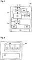
- the probe main body 302 has a first identification code 330 and a second identification code 340. More specifically, as shown in Fig. 3 , the probe main body 302 includes a suspension mechanism 320, a measurement unit 322, the first identification code 330, and a communication unit 332.
- the probe main body 302 is supplied with power from the coordinate measuring machine main body 200 or the processing device 400 via the connector CN.
- the suspension mechanism 320 illustrated in Fig. 3 supports the stylus module 304 so as to be displaceable in any direction relative to the probe main body 302.
- the measurement unit 322 includes analog sensors 323 and 324, and an ADC 325.
- the analog sensors 323 and 324 detect a change in the position of the stylus module 304.
- the ADC 325 is a converter (analog-to-digital converter) configured to convert an analog output signal from the analog sensors 323 and 324 to a digital signal.
- the first identification code 330 is shown, for example, by a resistor.
- the resistance value of the resistor is identified by the processing device 400. That is, the first identification code 330 is to be outputted as analog data from the measuring probe 300. Note that since the measuring probe 300 has the second identification code 340, the first identification code 330 is adapted to be matched (coincide) with a matching code MC that is positively identified by a particular resistance value.
- the communication unit 332 includes a processing portion 333, a communication portion 334, and a storage portion 335 configured to store the second identification code 340.
- the processing portion 333 may be an FPGA (may also be a PLC, an ASIC, or a microcomputer).
- the processing portion 333 processes signals from the ADC 325 and produces a probe signal PS.
- the processing portion 333 controls the communication portion 334 and the storage portion 335, and outputs from the communication portion 334, as appropriate, the probe signal PS or various types of information stored in the storage portion 335, for example, to the processing device 400 external to the measuring probe 300.
- the communication portion 334 employs the RS485 scheme (may also employ other communication schemes such as the RS232C or I 2 C) to perform serial communications.
- the communication portion 334 receives a transmission request from the processing device 400 and then outputs various signals (including data or codes) to the processing device 400 (i.e., the second identification code 340 is outputted as digital data from the measuring probe 300).
- the storage portion 335 stores calibration information 336 and the second identification code 340.
- the calibration information 336 serves to calibrate the measuring probe 300 and is outputted to the processing device 400 after the second identification code 340 is processed and then identified by the processing device 400.
- the second identification code 340 includes specific information 342 of the probe main body 302, specific information 344 of the stylus module 304, and other supplementary specific information 346 that is set as required.
- the specific information 342 of the probe main body 302 has information relating to at least one of the type, shape, weight, and center of gravity of the entirety of the probe main body 302 and an individual component of the probe main body 302, and the specific information 344 of the stylus module 304 has information relating to at least one of the type, shape, weight, and center of gravity of the entirety of the stylus module 304 and an individual component of the stylus module 304.
- the probe main body 302 is a single entity, and the specific information 342 is adapted to have information relating to the type, shape, weight, and center of gravity of the entirety of the probe main body 302.
- the specific information 342 further has information relating to the plurality of modules. That is, at that time, the specific information 342 is adapted to have information relating to the type, shape, weight, and center of gravity of each individual component (individual module) of the probe main body 302. Meanwhile, the specific information 344 is adapted to have information relating to the type, shape, weight, and center of gravity of each individual component of the flange 304A, the stem 304B, and the contact part 304C, and information relating to the type, shape, weight, and center of gravity of the entirety of the stylus module 304 (thus, the specific information 344 also has information relating to the stem 304B). Furthermore, each of the specific information 342 of the probe main body 302 and the specific information 344 of the stylus module 304 has manufacturer information.
- a simplified mark for example, an optical or magnetic barcode
- a sensor not illustrated
- the measuring probe 301 illustrated in Fig. 2 does not have the second identification code but has only the first identification code 331.
- the measuring probe 301 is configured generally in the same manner as the measuring probe 300 except that the measuring probe 301 does not have the second identification code. Thus, it is possible to selectively connect either the measuring probe 300 or the measuring probe 301 to the coordinate measuring machine main body 200.
- the operation unit 110 is connected to the processing device 400. It is possible to input various commands from the operation unit 110 to the coordinate measuring machine main body 200 and the processing device 400.
- the processing device 400 includes a motion controller 500 and a host computer 600. Then, the processing device 400 computes the shape coordinates of the object to be measured W on the basis of the output from the measuring probe 300 (301) including the probe signal PS and the amount of three-dimensional displacement of the measuring probe 300 (301) itself by the drive mechanism 220.
- the motion controller 500 mainly controls the three-dimensional displacement and the motion, at the time of measurement, of the measuring probe 300 (301) itself in response to a displacement command from the host computer 600.
- the host computer 600 mainly processes the measurement result acquired by the coordinate measuring machine main body 200. In this embodiment, Fig.
- the host computer 600 includes an input unit 120 such as a keyboard, and an output unit 130 such as a display or a printer.
- the processing device 400 includes a selector unit 420, a plurality of (two in this embodiment) probe signal processing interface (I/F) units 430 and 440, and a processing main body unit 450.
- the selector unit 420 is readily detachable, and the number of the probe signal processing I/F units 430 and 440 varies depending on the number of types of measuring probes 300 (301) that are used at a time.
- the selector unit 420 determines that the measuring probe 300 (301) connected to the probe head 225 is the measuring probe 300, and then outputs the first identification code (330) to a first determination portion 431 of the probe signal processing I/F unit 430.
- the selector unit 420 determines that the measuring probe 300 (301) connected to the probe head 225 is the measuring probe 301, and then outputs the first identification code (331) to a second determination portion 441 of the probe signal processing I/F unit 440.
- the selector unit 420 includes a determination portion 422, a relay portion 424, and a setting portion 426.
- the determination portion 422 identifies the first identification code 330 (331) of the measuring probe 300 (301). More specifically, the determination portion 422 compares the potential difference caused by the resistance value corresponding to the first identification code 330 (331) with a reference voltage serving as a reference, and then identifies the first identification code 330 (331) from the comparison result. On the basis of the first identification code 330 (331) thus identified, either one of the plurality of the probe signal processing I/F units 430 and 440 to be connected to the selector unit 420 is effectively connected thereto by the relay portion 424.
- the setting portion 426 sets the first identification code 330 (331) to the probe signal processing I/F unit 430 or 440 again.
- the relay portion 424 includes a first relay portion 424A, a second relay portion 424B, and a third relay portion 424C.
- the setting portion 426 includes a first setting portion 426A, a second setting portion 426B, and a third setting portion 426C.
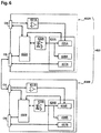
- the probe signal processing I/F unit 430 includes the first determination portion 431, a relay portion 432, a communication portion 433, and a downstream determination portion 435.
- the probe signal processing I/F unit 430 is configured from one master I/F unit 430A and one or more slave I/F units 430B.
- the master I/F unit 430A includes a first determination portion 431A, a relay portion 432A, a communication portion 433A, and a downstream determination portion 435A of a processing portion 434A.
- the master I/F unit 430A and the slave I/F unit 430B have generally the same outer shape and configuration, and the total number of master I/F units 430A and slave I/F units 430B is prepared corresponding to the number of the second identification codes 340. That is, the processing device 400 includes the downstream determination portions 435 the number of which corresponds to the number of the measuring probes 300 to be recognized (each having a specific second identification code 340). For example, in the processing device 400, the master I/F unit 430A is connected in series to the slave I/F unit 430B upstream thereof and identifies the first identification code and the second identification code prior to the slave I/F unit 430B.
- the first determination portion 431A determines whether the first identification code 330 outputted from the measuring probe 300 is matched with the matching code MC. That is, the first determination portion 431A has generally the same function as that of the determination portion 422. Note that it is also possible to eliminate the first determination portion 431A which has the function that overlaps that of the determination portion 422 of the selector unit 420.
- the relay portion 432A when the first determination portion 431A has determined that the first identification code 330 is matched with the matching code MC, the relay portion 432A enables communications between the communication portion 433A and the communication portion 334 of the measuring probe 300.
- the relay portion 432A also controls the reception state of the probe signal PS in the processing portion 434A according to whether or not the second identification code 340 is identified by the downstream determination portion 435A of the processing portion 434A. Note that the relay portion 432A has generally the same function as that of the first relay portion 424A.
- the communication portion 433A sends, to the measuring probe 300, a request for output of the second identification code 340, so that the measuring probe 300 is caused to output the second identification code 340.
- the communication portion 433A has generally the same function as that of the communication portion 334.
- the processing portion 434A includes the downstream determination portion 435A, a probe signal processing portion 436A, and an I/F control portion 437A, thus having generally the same function as that of the processing portion 333.
- the downstream determination portion 435A identifies the second identification code 340 outputted from the measuring probe 300 via the communication portion 433A. That is, when the first identification code 330 is matched with the matching code MC and the measuring probe 300 further has the second identification code, the downstream determination portion 435A identifies the second identification code outputted from the measuring probe 300 to thereby recognize the measuring probe 300. Furthermore, the downstream determination portion 435A controls the relay portion 432A.
- the probe signal processing portion 436A reads the calibration information 336 stored in the storage portion 335 of the measuring probe 300, and then calibrates the probe signal PS on the basis of the calibration information 336. That is, the processing device 400 reads the calibration information 336 corresponding to the measuring probe 300, which has been recognized, from the storage portion 335, and then computes the shape coordinates on the basis of the calibration information 336. Note that it is also possible for the motion controller 500 to calibrate the probe signal PS on the basis of the calibration information 336.
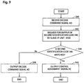
- the I/F control portion 437A illustrated in Fig. 6 exchanges, with the measuring probe 300, a signal that enables determination as to which of the master I/F unit 430A and the slave I/F unit 430B is effective. For example, when the second identification code 340 is successfully identified by the downstream determination portion 435A, the I/F control portion 437A outputs a control assignment signal HC. When the second identification code 340 was not successfully identified by the downstream determination portion 435A, the I/F control portion 437A outputs a decode command signal AO.
- an I/F control portion 437B of the slave I/F unit 430B operates to identify the second identification code 340.
- the identification of the second identification code 340 is firstly done by the master I/F unit 430A that is disposed upstream of the aforementioned serial connection.
- the master I/F unit 430A and the slave I/F unit 430B are controlled, for example, by the decode command signal AO.
- the operation to identify the second identification code 340 can be smoothly performed without any operational collision with each other.
- the probe signal processing I/F unit 440 includes the second determination portion 441 for recognizing the measuring probe 301.
- the second determination portion 441 identifies the first identification code 331 to recognize the measuring probe 301.
- the second determination portion 441 is configured generally in the same manner as the first determination portion 431 and compares a potential difference caused by a resistance value not corresponding to a matching code MC with another reference potential serving as another reference, thereby identifying the first identification code 331 from the comparison result.
- the probe signal processing I/F unit 440 allows the second determination portion 441 to identify the first identification code 331 and a probe signal processing portion (not shown) to process the probe signal PS.
- the probe signal processing I/F unit 440 may exchange, with an I/F control portion (not shown), a signal that enables determining as to which of the probe signal processing I/F units 430 and 440 is effective.
- the processing main body unit 450 is connected to the probe signal processing I/F units 430 and 440.
- the processing main body unit 450 controls and processes the recognition of the measuring probes 300 and 301 which is performed by the probe signal processing I/F units 430 and 440.
- the processing main body unit 450 reflects the calibration value of the probe signal PS and combines the output of the measuring probe 300 (301) with the amount of three-dimensional displacement by the drive mechanism 220.
- the processing main body unit 450 causes the output portion 130 to output an error signal when the state with no control assignment signal HC received continues for a predetermined duration or longer.
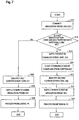
- the measuring probe 300 (301) is connected to the coordinate measuring machine main body 200 ( Fig. 7 , step S10).
- the selector unit 420 supplies power to a resistor corresponding to the first identification code 330 (331) of the measuring probe 300 (301). Then, the process determines whether the first identification code 330 (331) outputted from the measuring probe 300 (301) is matched with the matching code MC ( Fig. 7 , step S12).
- the process identifies the second identification code 340 outputted from the measuring probe 300 to thereby recognize the measuring probe 300.
- the selector unit 420 outputs the first identification code 330 to the first determination portion 431 of the probe signal processing I/F unit 430. Then, the first determination portion 431 of the probe signal processing I/F unit 430 checks (determines) again that the first identification code 330 is matched with the matching code MC. When the first identification code 330 is matched with the matching code MC, the probe signal processing I/F unit 430 supplies power to the communication unit 332 of the measuring probe 300 ( Fig. 7 , step S14).
- the communication portion 433 starts communications with the communication portion 334 via the relay portion 432 ( Fig. 7 , step S16). More specifically, the communication portion 433 transmits an output request for the second identification code 340 to the communication portion 334, so that the communication portion 334 is caused to output the second identification code 340.
- the process identifies the second identification code 340 ( Fig. 7 , step S18). Then, the process recognizes the measuring probe 300. This processing will be discussed later with reference to Figs. 8 and 9 .
- the first identification code 330 is matched with the matching code MC, it is ensured that the second identification code 340 exists in the measuring probe 300. That is, it can also be said that to check that the first identification code 330 is matched with the matching code MC is to check whether or not the second identification code 340 is found in the measuring probe 300.
- the probe signal processing I/F unit 430 can produce an error signal and output the error state to the output unit 130.
- the probe signal processing I/F unit 430 supplies power to the entire measuring probe 300 ( Fig. 7 , step S20). Since the communication unit 332 of the measuring probe 300 is supplied with power, the probe signal processing I/F unit 430 supplies power to the measurement unit 322 of the measuring probe 300.
- the probe signal processing I/F unit 430 causes the measuring probe 300 to output the probe signal PS.
- the probe signal processing portion 436A, 436B processes the probe signal PS ( Fig. 7 , step S22).
- the selector unit 420 outputs the first identification code 331 to the second determination portion 441 of the probe signal processing I/F unit 440. Then, when the determination shows that the first identification code 331 is not matched with the matching code MC, the first identification code 331 is identified to thereby recognize the measuring probe 301.
- the process identifies that the determination shows that the first identification code 330 (331) is not matched with the matching code MC, and the selector unit 420 has another code.
- the selector unit 420 outputs the first identification code 331 to the second determination portion 441 of the probe signal processing I/F unit 440 corresponding to the another code.
- the second determination portion 441 identifies again that the first identification code 331 is another code different from the matching code MC ( Fig. 7 , step S24) .
- the probe signal processing I/F unit 440 supplies power to the entire measuring probe 301 ( Fig. 7 , step S26).
- the probe signal processing I/F unit 440 causes the measuring probe 301 to output the probe signal PS. Then, the probe signal processing portion of the probe signal processing I/F unit 440 processes the probe signal PS ( Fig. 7 , step S28).
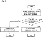
- the communication portion 433A of the master I/F unit 430A requests the communication portion 334 of the measuring probe 300 to output the second identification code 340 ( Fig. 8 , step S30).
- the downstream determination portion 435A determines the matching of the second identification code 340 outputted from the measuring probe 300 ( Fig. 8 , step S32). For example, the downstream determination portion 435A reads an equivalent code corresponding to the second identification code 340 stored in a storage portion (not shown) and then compares the resulting code with the second identification code 340. Then, the comparison result indicative of coinciding ( Fig. 8 , Yes in step S32) shows the matching and identifying of the second identification code 340. This causes the I/F control portion 437A of the master I/F unit 430A to output the control assignment signal HC ( Fig. 8 , step S34). At this time, the master I/F unit 430A itself has identified the second identification code 340 and is thus to also process the probe signal PS.
- the comparison result indicative of no coinciding shows that the second identification code 340 has not been identified. This causes the I/F control portion 437A to output the decode command signal AO ( Fig. 8 , step S36). At this time, the master I/F unit 430A identifies no second identification code 340 and is thus to also process no probe signal PS.
- the I/F control portion 437B of the slave I/F unit 430B connected downstream of the master I/F unit 430A receives the decode command signal AO ( Fig. 9 , step S40).
- the processing in the slave I/F unit 430B ( Fig. 9 , steps S42 to S48) is the same as the processing in the master I/F unit 430A ( Fig. 8 , steps S30 to S36), and thus will not be repeatedly described. Note that when the slave I/F unit 430B also processes no probe signal PS, the processing will be performed by another slave I/F unit connected in series downstream of the slave I/F unit 430B.
- the processing device 400 includes the first determination portion 431, and the downstream determination portion 435 that identifies the second identification code 340 to thereby recognize the measuring probe 300 when the first identification code 330 is matched with the matching code MC and the measuring probe 300 further has the second identification code 340. That is, in this embodiment, it is possible to recognize an enormous number of measuring probes 300 with a combination of the first identification code 330 and the second identification code 340. Furthermore, in this embodiment, since the second identification code 340 is identified when the first identification code 330 is matched with the matching code MC, the downstream determination portion 435 does not need to operate for the measuring probe 301 having no second identification code 340. It is therefore possible to recognize the measuring probe 300 efficiently by the processing device 400. Furthermore, in this embodiment, even the measuring probe 301 having no second identification code 340 can constitute the coordinate measuring machine 100.
- the processing device 400 is provided, in the probe signal processing I/F unit 440, with the second determination portion 441 configured to recognize the measuring probe 301. That is, in this embodiment, it is possible to recognize the measuring probe 301 even for the measuring probe 301 having no second identification code 340.
- the present invention is not limited thereto and, when only measuring probes having both the first and second identification codes are connected to the coordinate measuring machine main body, the probe signal processing I/F unit including the second determination portion may be eliminated.
- the processing device 400 further includes the selector unit 420.
- the measuring probe 300, 301 can be connected to the coordinate measuring machine main body 200, so that the measuring probe 300 and the measuring probe 301 can be automatically recognized.
- the present invention is not limited thereto and, when a measuring probe having no second identification code is connected to the coordinate measuring machine main body, the measuring probe may also be manually connected to the probe signal processing I/F unit. That is, the selector unit may also be eliminated.
- the first identification code 330, 331 is outputted as analog data from the measuring probe 300, 301. That is, outputting the first identification code 330, 331 from the measuring probe 300, 301 does not require complicated control or arrangement but only a simplified technique. Furthermore, the first identification code 330, 331 is identified by a resistance value. Thus, in this embodiment, since the conventional technique for recognizing measuring probes that are specified by the resistance value can be used without being changed, the conventional measuring probe 301 can also be used without any change made thereto. Note that the present invention is not limited thereto and the first identification code, which may be analog data, can also be specified in the capacity or impedance. As a matter of course, the first identification code may also be outputted as digital data. Then, the first identification code may be outputted not only via electrical wiring but also wirelessly.
- the second identification code 340 is outputted as digital data from the measuring probe 300.
- the second identification code may also be outputted as analog data.
- the second identification code may be outputted not only via electrical wiring but also wirelessly.
- the processing device 400 includes the communication portion 433 configured to output the second identification code 340 from the measuring probe 300.
- the measuring probe 300 it is possible to operate the measuring probe 300 with efficiency in terms of power (in a low consumption mode).
- the second identification code 340 is not outputted when the first identification code 330 is outputted to identify the first identification code 330, it is possible to prevent the second identification code 340 from exerting an influence on identifying the first identification code 330.
- the first identification code 330 is analog data and the second identification code 340 is digital data, and the two pieces of data are outputted at the same time.
- the first identification code 330 is also outputted when the second identification code 340 is outputted to identify the second identification code 340.
- the second identification code 340 is digital data and thus hardly influenced by the first identification code 330 that is analog data.
- the present invention is not limited thereto, and the second identification code may also be outputted from the measuring probe not under the condition that the first identification code is matched with the matching code MC.
- the second identification code 340 includes the specific information 342 of the probe main body 302 and the specific information 344 of the stylus module 304. That is, in this embodiment, even when the stylus module 304 and the probe main body 302 are changed, the second identification code 340 can completely cover the combinations thereof.
- the present invention is not limited thereto, and the measuring probe may not be separated into the stylus module and the probe main body but may be configured integrally. As a matter of course, the measuring probe may include the stylus module and the probe main body, and the second identification code may include only the specific information of the probe main body.
- the specific information 342 of the probe main body 302 has information relating to the type, shape, weight, and center of gravity of the entirety of the probe main body 302 and the individual component of the probe main body 302
- the specific information 344 of the stylus module 304 has information relating to the type, shape, weight, and center of gravity of the entirety of the stylus module 304 and the individual component of the stylus module 304.
- the present invention is not limited thereto, and each specific information may also include only information (factor) relating to any one of the type, shape, weight, and center of gravity of the entirety or the individual component.
- each specific information may not need to include any information relating to the type, shape, weight, and center of gravity of the entirety or the individual component.
- each specific information 342, 344 may have manufacturer information. In this embodiment, this makes it possible to calibrate even a slight difference in measurement property between measuring probes 300 that may come from a difference between manufacturers. Note that the present invention is not limited thereto, and each specific information may also have no manufacturer information.
- the probe main body 302 is made separable into a plurality of modules, and the specific information 342 can further have information relating to the plurality of modules. That is, in this embodiment, even when a combination of the modules is changed, grasping information relating to each of the plurality of modules enables accurate reflection of the change.
- the present invention is not limited thereto, and the specific information of the probe main body needs not to have information relating to all of the plurality of modules but may only have information relating to some modules concerning measurement properties.
- the specific information 344 further has information relating to the stem 304B.
- the technique is to further provide the probe main body 302 with a weight sensor or to use a suspension mechanism configured to support the stylus module 304. First, with the measuring probe 300 at a standstill, a change in the weight of the stylus module 304 is detected.
- a change in inertial moment when the measuring probe 300 is moved and stopped is used to detect a change in the position of the center of gravity of the stylus module 304. Then, on the basis of those amounts of change, the correct weight and center of gravity are determined.
- the present invention is not limited thereto, and the specific information may also have no information relating to the stem.
- the processing device 400 reads the calibration information 336 from the storage portion 335 to compute shape coordinates on the basis of the calibration information 336.
- the shape coordinates determined by the computation using the calibration information can be made independent of the measurement properties of each measuring probe 300.
- the present invention is not limited thereto, and it is also acceptable to perform no calibration on the shape coordinates determined by a measuring probe but only to recognize the measuring probe in order to make clear the identity of the measuring probe.
- the measuring probe 300 includes the storage portion 335 for storing the calibration information 336.
- the processing device may include a storage portion configured to store calibration information.
- the master I/F unit 430A and the slave I/F unit 430B are configured in the same manner.
- the master I/F unit 430A and the slave I/F unit 430B differ from each other in that the units are located upstream or downstream when connected in series and can thus be used for two mutually different measuring probes 300.
- the master I/F unit 430A and the slave I/F unit 430B may only have to be prepared depending on the number of the measuring probes 300 to be used, the master I/F unit 430A and the slave I/F unit 430B can be made readily available for the measuring probes 300. Note that the present invention is not limited thereto, and the master I/F unit and the slave I/F unit may not have to be configured in the same manner.
- the processing device 400 includes the downstream determination portions 435 the number of which corresponds to the number of the measuring probes 300 to be recognized.
- the downstream determination portions 435 do not need to match, with each other, the determination factor, the determination sequential order, and the determination reference at the downstream determination portions 435. That is, in this embodiment, it is possible to optimally configure the downstream determination portion 435 in identifying the second identification code 340 and recognizing each measuring probe 300.
- the present invention is not limited thereto, and the probe signal processing I/F unit may only include the storage portions the number of which corresponds to the number of the measuring probes, so that one downstream determination portion may be employed to be common to the plurality of measuring probes. That is, the invention may be configured in a manner such that one probe signal processing I/F unit is employed to make a plurality of measuring probes available. In this case, the probe signal processing I/F unit can be minimized, and the processing device can be reduced in size and costs.
- the measuring probe 300, 301 is a scanning probe, but it may also be a touch trigger probe or a non-contact optical probe.
- the contact part may not have to be spherical in shape, but may also have a disc shape, for example.
- the measuring probe 300, 301 is connected to the coordinate measuring machine main body 200 to constitute a coordinate measuring unit.
- the measuring probe may also be connected to the main body of a machine tool instead of a tool so as to constitute a coordinate measuring unit.
- the measuring probe 300, 301 is supplied with power by the coordinate measuring machine main body 200 or the processing device 400.
- the present invention is not limited thereto, and may also be configured such that the measuring probe itself includes a power source.
- the present invention can be widely applied to coordinate measuring units configured to measure the three-dimensional shape of an object to be measured.
Landscapes
- Physics & Mathematics (AREA)
- General Physics & Mathematics (AREA)
- Engineering & Computer Science (AREA)
- Computer Hardware Design (AREA)
- Theoretical Computer Science (AREA)
- Mathematical Physics (AREA)
- Computer Security & Cryptography (AREA)
- Software Systems (AREA)
- General Engineering & Computer Science (AREA)
- Length Measuring Devices With Unspecified Measuring Means (AREA)
- A Measuring Device Byusing Mechanical Method (AREA)
Claims (16)
- Koordinatenmessungseinheit (100), die eine Messsonde (300, 301) und eine Verarbeitungsvorrichtung (400) umfasst, die konfiguriert ist, Formenkoordinaten eines zu messenden Objekts (W) auf einer Basis einer Ausgabe der Messsonde (300, 301) zu berechnen, wobei
die Messsonde (300, 301) einen ersten Identifikationscode (330, 331) aufweist; und
die Verarbeitungsvorrichtung (400) beinhalteteinen ersten Bestimmungsabschnitt (431, 431A, 431B), der konfiguriert ist zu bestimmen, ob der erste Identifikationscode (330, 331), der von der Messsonde (300, 301) ausgegeben wurde, mit einem Übereinstimmungscode (MC) übereinstimmt,einen stromabwärtigen Bestimmungsabschnitt (435, 435A, 435B), der konfiguriert ist, einen zweiten Identifikationscode (340) zu identifizieren, der von der Messsonde (300) ausgegeben wurde, um dadurch die Messsonde (300) zu erkennen, wenn der erste Identifikationscode (330) mit dem Übereinstimmungscode (MC) in dem ersten Bestimmungsabschnitt (431, 431A, 431B) übereinstimmt und die Messsonde (300) weiter den zweiten Identifikationscode (340) aufweist, undeinen Kommunikationsabschnitt (433, 433A, 433B), der konfiguriert ist, wenn der erste Übereinstimmungscode (330) mit dem Übereinstimmungscode (MC) in dem ersten Bestimmungsabschnitt (431, 431A, 431B) übereinstimmt, der Messsonde (300) eine Anfrage zur Ausgabe des zweiten Identifikationscodes (340) zu senden und die Messsonde (300) zu veranlassen, den zweiten Identifikationscode (340) auszugeben. - Koordinatenmessungseinheit (100) nach Anspruch 1, wobei eine Auswahleinheit (420) der Verarbeitungsvorrichtung (400) angepasst ist, den ersten Identifikationscode (330, 331) von der Messsonde (300, 301) ausgeben zu lassen, indem Strom an einen Widerstand entsprechend dem ersten Identifikationscode (330, 331) der Messsonde (300, 301) versorgt wird, und eine Sondensignalverarbeitungs-I/FEinheit (430) der Verarbeitungsvorrichtung (400) angepasst ist, Kommunikation zwischen dem Kommunikationsabschnitt (433) und einem Kommunikationsabschnitt (334) einer Kommunikationseinheit (332) der Messsonde (300) starten zu lassen, indem Strom an die Kommunikationseinheit (332) versorgt wird.
- Koordinatenmessungseinheit (100) nach Anspruch 2, wobei die Verarbeitungsvorrichtung (400) weiter einen zweiten Bestimmungsabschnitt (441) beinhaltet, der konfiguriert ist, wenn der erste Identifikationscode (331) nicht mit dem Übereinstimmungscode (MC) übereinstimmt, den ersten Identifikationscode (331) zu identifizieren, um dadurch die Messsonde (301) zu erkennen.
- Koordinatenmessungseinheit (100) nach Anspruch 3, wobei die Auswahleinheit (420) konfiguriert ist, den ersten Identifikationscode (330) an den ersten Bestimmungsabschnitt (431, 431A, 431B) auszugeben, wenn der erste Identifikationscode (330) mit dem Übereinstimmungscode (MC) übereinstimmt, und den ersten Identifikationscode (331) an den zweiten Bestimmungsabschnitt (441) auszugeben, wenn der erste Identifikationscode (331) nicht mit dem Übereinstimmungscode (MC) übereinstimmt.
- Koordinatenmessungseinheit (100) nach einem der Ansprüche 2 bis 4, wobei die Sondensignalverarbeitungs-I/F-Einheit (430) der Verarbeitungsvorrichtung (400) angepasst ist, Strom an die gesamte Messsonde (300, 301) zu versorgen, wenn die Messsonde (300, 301) erkannt wurde.
- Koordinatenmessungseinheit (100) nach einem der Ansprüche 1 bis 5, wobei der erste Identifikationscode (330, 331) als analoge Daten von der Messsonde (300, 301) ausgegeben wird.
- Koordinatenmessungseinheit (100) nach einem der Ansprüche 1 bis 6, wobei der zweite Identifikationscode (340) als digitale Daten von der Messsonde (300) ausgegeben wird.
- Koordinatenmessungseinheit (100) nach einem der Ansprüche 1 bis 7, wobei die Messsonde (300, 301) ein Stiftmodul (304, 305), das ein Kontaktteil (304C, 305C) aufweist, das dazu konfiguriert ist, das zu messende Objekt (W) zu detektieren, und einen Sondenhauptteil (302, 303), das konfiguriert ist, den Stiftmodus (304, 305) zu unterstützen, beinhaltet, und
der zweite Identifikationscode (340) spezifische Informationen (342) des Sondenhauptteils (302) und spezifische Informationen (344) des Stiftmoduls (304) beinhaltet. - Koordinatenmessungseinheit (100) nach Anspruch 8, wobei die spezifischen Informationen (342) des Sondenhauptteils (302) Informationen bezüglich mindestens eines von einem Typ, einer Form, einem Gewicht und einem Schwerpunkt einer Gesamtheit des Sondenhauptteils (302) und einer individuellen Komponente des Sondenhauptteils (302) aufweisen und die spezifischen Informationen (344) des Stiftmoduls (304) Informationen bezüglich mindestens eines von einem Typ, einer Form, einem Gewicht und einem Schwerpunkt einer Gesamtheit des Stiftmoduls (304) und einer individuellen Komponente des Stiftmoduls (304) aufweisen.
- Koordinatenmessungseinheit (100) nach Anspruch 9, wobei sowohl die spezifischen Informationen (342) des Sondenhauptteils (302) als auch die spezifischen Informationen (344) des Stiftmoduls (304) weiter Herstellerinformationen aufweisen.
- Koordinatenmessungseinheit (100) nach einem der Ansprüche 8 bis 10, wobei der Sondenhauptteil (302) in eine Vielzahl von Modulen zerteilbar hergestellt ist und die spezifischen Informationen (342) des Sondenhauptteils (302) weiter Informationen bezüglich der Vielzahl von Modulen aufweisen.
- Koordinatenmessungseinheit (100) nach einem der Ansprüche 8 bis 11, wobei das Stiftmodul (304) einen Stiel (304B) beinhaltet, der konfiguriert ist, das Kontaktteil (304C) zu stützen, und die spezifischen Informationen (344) des Stiftmoduls (304) weiter Informationen bezüglich des Stiels (304B) aufweisen.
- Koordinatenmessungseinheit (100) nach einem der Ansprüche 1 bis 12, weiter umfassend einen Speicherabschnitt (335), der konfiguriert ist, Kalibrierungsinformationen (336) der Messsonde (300) zu speichern, wobei
die Verarbeitungsvorrichtung (400) angepasst ist, die Kalibrierungsinformationen (336) entsprechend der erkannten Messsonde (300) aus dem Speicherabschnitt (335) zu lesen und die Formkoordinaten unter Verwendung der Kalibrierungsinformationen (336) zu berechnen. - Koordinatenmessungseinheit (100) nach einem der Ansprüche 1 bis 13, wobei die Verarbeitungsvorrichtung (400) eine Zahl von stromabwärtigen Bestimmungsabschnitten (435, 435A, 435B) beinhaltet, deren Zahl einer Zahl der zu erkennenden Messsonden (300) entspricht.
- Verfahren zum Erkennen einer Messsonde (300, 301) in einer Koordinatenmessungseinheit (100), die konfiguriert ist, Formkoordinaten eines zu messenden Objekts (W) auf einer Basis einer Ausgabe einer Messsonde (300, 301) zu berechnen, wobei das Verfahren umfasst:Bestimmen, ob ein erster Identifikationscode (330, 331), der von der Messsonde (300, 301) ausgegeben wurde und den die Messsonde (300, 301) aufweist, mit einem Übereinstimmungscode (MC) übereinstimmt;wenn der erste Identifikationscode (330) mit dem Übereinstimmungscode (MC) übereinstimmt, Anfragen der Messsonde (300), einen zweiten Identifikationscode (340) auszugeben, um dadurch den zweiten Identifikationscode (340) von der Messsonde (300) durch ihre Bestimmung auszugeben; undIdentifizieren des zweiten Identifikationscodes (340), der von der Messsonde (300) ausgegeben wurde, um dadurch die Messsonde (300) zu erkennen, wenn die Messsonde (300) weiter den zweiten Identifikationscode (340) aufweist.
- Verfahren zum Erkennen einer Messsonde (300, 301) nach Anspruch 15, weiter umfassend, wenn der erste Identifikationscode (331) nicht mit dem Übereinstimmungscode (MC) durch die Bestimmung übereinstimmt, Erkennen der Messsonde (301) durch Identifizieren des ersten Identifikationscodes (331).
Applications Claiming Priority (1)
| Application Number | Priority Date | Filing Date | Title |
|---|---|---|---|
| JP2017123763A JP6491698B2 (ja) | 2017-06-23 | 2017-06-23 | 三次元測定ユニット及び測定プローブの識別方法 |
Publications (2)
| Publication Number | Publication Date |
|---|---|
| EP3418683A1 EP3418683A1 (de) | 2018-12-26 |
| EP3418683B1 true EP3418683B1 (de) | 2021-05-05 |
Family
ID=62748797
Family Applications (1)
| Application Number | Title | Priority Date | Filing Date |
|---|---|---|---|
| EP18179009.8A Active EP3418683B1 (de) | 2017-06-23 | 2018-06-21 | Koordinatenmesseinheit und verfahren zur erkennung einer messsonde |
Country Status (4)
| Country | Link |
|---|---|
| US (1) | US10788312B2 (de) |
| EP (1) | EP3418683B1 (de) |
| JP (1) | JP6491698B2 (de) |
| CN (1) | CN109115139B (de) |
Families Citing this family (6)
| Publication number | Priority date | Publication date | Assignee | Title |
|---|---|---|---|---|
| JP7072990B2 (ja) | 2018-06-22 | 2022-05-23 | 株式会社ミツトヨ | 測定装置および測定方法 |
| WO2020023515A1 (en) * | 2018-07-23 | 2020-01-30 | Hexagon Metrology, Inc. | Scanning jogbox |
| EP3891466B1 (de) | 2018-12-06 | 2024-01-31 | Hexagon Metrology, Inc | System und verfahren zur messung mit mehreren modalitäten |
| KR102682652B1 (ko) * | 2022-02-14 | 2024-07-08 | 주식회사 덕인 | 2개 이상의 프로브를 사용하는 3차원 측정기 |
| JP2024099962A (ja) * | 2023-01-13 | 2024-07-26 | 株式会社ミツトヨ | 測定システムおよび測定方法 |
| JP2024129449A (ja) * | 2023-03-13 | 2024-09-27 | シチズンマシナリー株式会社 | 工作機械及び工作機械の制御方法 |
Family Cites Families (19)
| Publication number | Priority date | Publication date | Assignee | Title |
|---|---|---|---|---|
| JPH0663724B2 (ja) * | 1982-10-11 | 1994-08-22 | レニショウ パブリック リミテッド カンパニー | 位置検知装置 |
| GB8522984D0 (en) | 1985-09-17 | 1985-10-23 | Renishaw Plc | Tool change apparatus |
| JPH07237067A (ja) * | 1994-02-28 | 1995-09-12 | Hitachi Zosen Corp | 工具管理装置 |
| JP3967429B2 (ja) * | 1997-08-29 | 2007-08-29 | 株式会社東芝 | 超音波診断装置 |
| JP2001137246A (ja) * | 1999-11-17 | 2001-05-22 | Olympus Optical Co Ltd | 超音波診断装置システム |
| DE10057284A1 (de) | 2000-11-17 | 2002-05-23 | Rolf Beck Kg | Verfahren zur Meßtaster-Identifikation |
| GB0115788D0 (en) | 2001-06-28 | 2001-08-22 | Renishaw Plc | Tool identification |
| DE202004011364U1 (de) | 2004-07-20 | 2004-09-09 | Klingelnberg Gmbh | Vorrichtung zum Erkennen eines an einem Messgerät verwendeten Messkopfes |
| GB0518078D0 (en) | 2005-09-06 | 2005-10-12 | Renishaw Plc | Signal transmission system |
| EP2018934A1 (de) * | 2007-07-26 | 2009-01-28 | Renishaw plc | Messvorrichtung mit Authentifizierungsmodul |
| DE102007053330B4 (de) | 2007-11-08 | 2019-01-31 | Blum-Novotest Gmbh | Verfahren zur Regelung der Sendeleistung einer Sende-/Empfangsvorrichtung in einem Positionsmesssystem für eine Maschine und Sende-/Empfangsvorrichtung |
| US8122610B2 (en) | 2008-03-28 | 2012-02-28 | Hexagon Metrology, Inc. | Systems and methods for improved coordination acquisition member comprising calibration information |
| JP5192283B2 (ja) * | 2008-05-13 | 2013-05-08 | 株式会社ミツトヨ | 三次元測定機 |
| JP6257930B2 (ja) * | 2012-08-07 | 2018-01-10 | 東芝メディカルシステムズ株式会社 | 超音波診断装置および超音波プローブ |
| CN203313523U (zh) | 2013-05-23 | 2013-11-27 | 深圳深超换能器有限公司 | 兼容探头的识别电路组合结构 |
| DE102013105753B3 (de) * | 2013-06-04 | 2014-10-02 | Carl Zeiss Industrielle Messtechnik Gmbh | Verfahren zum automatischen Aufnehmen eines Sensorkopfs und Koordinatenmessgerät |
| US9651361B2 (en) * | 2014-10-08 | 2017-05-16 | Faro Technologies, Inc. | Coordinate measurement machine with redundant energy sources |
| EP3472556B1 (de) * | 2016-06-15 | 2023-08-23 | Hexagon Metrology, Inc. | Kmg-vorrichtung zum identifizieren und bestätigen eines taststifts |
| JP7053671B2 (ja) * | 2017-06-30 | 2022-04-12 | 株式会社ミツトヨ | 座標測定機用の自己構成要素識別および信号処理システム |
-
2017
- 2017-06-23 JP JP2017123763A patent/JP6491698B2/ja active Active
-
2018
- 2018-06-20 US US16/013,467 patent/US10788312B2/en active Active
- 2018-06-21 EP EP18179009.8A patent/EP3418683B1/de active Active
- 2018-06-22 CN CN201810654941.5A patent/CN109115139B/zh active Active
Also Published As
| Publication number | Publication date |
|---|---|
| CN109115139B (zh) | 2020-11-13 |
| CN109115139A (zh) | 2019-01-01 |
| JP2019007840A (ja) | 2019-01-17 |
| JP6491698B2 (ja) | 2019-03-27 |
| US20180372480A1 (en) | 2018-12-27 |
| US10788312B2 (en) | 2020-09-29 |
| EP3418683A1 (de) | 2018-12-26 |
Similar Documents
| Publication | Publication Date | Title |
|---|---|---|
| EP3418683B1 (de) | Koordinatenmesseinheit und verfahren zur erkennung einer messsonde | |
| EP0236414B1 (de) | Werkzeugwechselapparat | |
| EP0180610B1 (de) | Verbesserung bezüglich eines koordinaten positionierungsapparates | |
| US6665588B2 (en) | Workpiece unloading apparatus | |
| CN109211155B (zh) | 用于坐标测量机的自配置部件识别和信号处理系统 | |
| EP1559990A2 (de) | Koordinatenmesssystem und Verfahren zur Korrektur der Koordinaten die an eine Koordinatenmessgerät gemessen wurden | |
| JPWO2009057229A1 (ja) | エラーマップ作成方法及び装置並びにエラーマップ作成機能を有した数値制御工作機械 | |
| US10458772B2 (en) | CMM apparatus for identifying and confirming the stylus | |
| EP3423785A1 (de) | Verfahren und vorrichtung zur kalibrierung einer abtastsonde | |
| US20050268680A1 (en) | Location and identification of a tool in a tool receiving part | |
| US20110258358A1 (en) | Device and Method for the Automated Detection of an Interface | |
| JPH09223896A (ja) | 電子部品実装機の部品管理システム | |
| KR102460118B1 (ko) | 어태치먼트 중심위치의 보정방법 | |
| WO1992020996A1 (en) | A method of measuring workpieces using a surface contacting measuring probe | |
| CN114740151A (zh) | 二氧化碳传感器智能标定检测方法及装置 | |
| CN107632566A (zh) | 一种板卡识别装置、方法和网络设备 | |
| CN118456080A (zh) | 工具转换系统 | |
| US20250251229A1 (en) | Measurement probe head identification | |
| JPH10225844A (ja) | 数値制御工作機械の測定方法及び測定装置 | |
| US20250251231A1 (en) | Measurement probe head temperature compensation | |
| US20140088733A1 (en) | Apparatus and Method for Machine Parameterization by Means of Smart Devices | |
| EP4722637A1 (de) | Verfahren zum betrieb eines messsystems | |
| EP1600257A1 (de) | Positionierung und Erkennung eines Werkzeuges in einer Werkzeughalterung | |
| JP5121292B2 (ja) | 形状測定方法及び装置 | |
| EP3950232A1 (de) | Verfahren zur prüfung eines behälters, der mindestens eine fahrzeugkomponente aufnehmen kann |
Legal Events
| Date | Code | Title | Description |
|---|---|---|---|
| PUAI | Public reference made under article 153(3) epc to a published international application that has entered the european phase |
Free format text: ORIGINAL CODE: 0009012 |
|
| STAA | Information on the status of an ep patent application or granted ep patent |
Free format text: STATUS: THE APPLICATION HAS BEEN PUBLISHED |
|
| AK | Designated contracting states |
Kind code of ref document: A1 Designated state(s): AL AT BE BG CH CY CZ DE DK EE ES FI FR GB GR HR HU IE IS IT LI LT LU LV MC MK MT NL NO PL PT RO RS SE SI SK SM TR |
|
| AX | Request for extension of the european patent |
Extension state: BA ME |
|
| STAA | Information on the status of an ep patent application or granted ep patent |
Free format text: STATUS: REQUEST FOR EXAMINATION WAS MADE |
|
| 17P | Request for examination filed |
Effective date: 20190605 |
|
| RBV | Designated contracting states (corrected) |
Designated state(s): AL AT BE BG CH CY CZ DE DK EE ES FI FR GB GR HR HU IE IS IT LI LT LU LV MC MK MT NL NO PL PT RO RS SE SI SK SM TR |
|
| STAA | Information on the status of an ep patent application or granted ep patent |
Free format text: STATUS: EXAMINATION IS IN PROGRESS |
|
| 17Q | First examination report despatched |
Effective date: 20190731 |
|
| GRAP | Despatch of communication of intention to grant a patent |
Free format text: ORIGINAL CODE: EPIDOSNIGR1 |
|
| STAA | Information on the status of an ep patent application or granted ep patent |
Free format text: STATUS: GRANT OF PATENT IS INTENDED |
|
| INTG | Intention to grant announced |
Effective date: 20200901 |
|
| GRAJ | Information related to disapproval of communication of intention to grant by the applicant or resumption of examination proceedings by the epo deleted |
Free format text: ORIGINAL CODE: EPIDOSDIGR1 |
|
| STAA | Information on the status of an ep patent application or granted ep patent |
Free format text: STATUS: EXAMINATION IS IN PROGRESS |
|
| INTC | Intention to grant announced (deleted) | ||
| GRAP | Despatch of communication of intention to grant a patent |
Free format text: ORIGINAL CODE: EPIDOSNIGR1 |
|
| STAA | Information on the status of an ep patent application or granted ep patent |
Free format text: STATUS: GRANT OF PATENT IS INTENDED |
|
| INTG | Intention to grant announced |
Effective date: 20210115 |
|
| GRAS | Grant fee paid |
Free format text: ORIGINAL CODE: EPIDOSNIGR3 |
|
| GRAA | (expected) grant |
Free format text: ORIGINAL CODE: 0009210 |
|
| STAA | Information on the status of an ep patent application or granted ep patent |
Free format text: STATUS: THE PATENT HAS BEEN GRANTED |
|
| AK | Designated contracting states |
Kind code of ref document: B1 Designated state(s): AL AT BE BG CH CY CZ DE DK EE ES FI FR GB GR HR HU IE IS IT LI LT LU LV MC MK MT NL NO PL PT RO RS SE SI SK SM TR |
|
| REG | Reference to a national code |
Ref country code: GB Ref legal event code: FG4D |
|
| REG | Reference to a national code |
Ref country code: CH Ref legal event code: EP |
|
| REG | Reference to a national code |
Ref country code: AT Ref legal event code: REF Ref document number: 1390337 Country of ref document: AT Kind code of ref document: T Effective date: 20210515 |
|
| REG | Reference to a national code |
Ref country code: IE Ref legal event code: FG4D |
|
| REG | Reference to a national code |
Ref country code: DE Ref legal event code: R096 Ref document number: 602018016494 Country of ref document: DE |
|
| REG | Reference to a national code |
Ref country code: LT Ref legal event code: MG9D |
|
| REG | Reference to a national code |
Ref country code: AT Ref legal event code: MK05 Ref document number: 1390337 Country of ref document: AT Kind code of ref document: T Effective date: 20210505 |
|
| PG25 | Lapsed in a contracting state [announced via postgrant information from national office to epo] |
Ref country code: LT Free format text: LAPSE BECAUSE OF FAILURE TO SUBMIT A TRANSLATION OF THE DESCRIPTION OR TO PAY THE FEE WITHIN THE PRESCRIBED TIME-LIMIT Effective date: 20210505 Ref country code: HR Free format text: LAPSE BECAUSE OF FAILURE TO SUBMIT A TRANSLATION OF THE DESCRIPTION OR TO PAY THE FEE WITHIN THE PRESCRIBED TIME-LIMIT Effective date: 20210505 Ref country code: FI Free format text: LAPSE BECAUSE OF FAILURE TO SUBMIT A TRANSLATION OF THE DESCRIPTION OR TO PAY THE FEE WITHIN THE PRESCRIBED TIME-LIMIT Effective date: 20210505 Ref country code: AT Free format text: LAPSE BECAUSE OF FAILURE TO SUBMIT A TRANSLATION OF THE DESCRIPTION OR TO PAY THE FEE WITHIN THE PRESCRIBED TIME-LIMIT Effective date: 20210505 Ref country code: BG Free format text: LAPSE BECAUSE OF FAILURE TO SUBMIT A TRANSLATION OF THE DESCRIPTION OR TO PAY THE FEE WITHIN THE PRESCRIBED TIME-LIMIT Effective date: 20210805 |
|
| PG25 | Lapsed in a contracting state [announced via postgrant information from national office to epo] |
Ref country code: RS Free format text: LAPSE BECAUSE OF FAILURE TO SUBMIT A TRANSLATION OF THE DESCRIPTION OR TO PAY THE FEE WITHIN THE PRESCRIBED TIME-LIMIT Effective date: 20210505 Ref country code: SE Free format text: LAPSE BECAUSE OF FAILURE TO SUBMIT A TRANSLATION OF THE DESCRIPTION OR TO PAY THE FEE WITHIN THE PRESCRIBED TIME-LIMIT Effective date: 20210505 Ref country code: PL Free format text: LAPSE BECAUSE OF FAILURE TO SUBMIT A TRANSLATION OF THE DESCRIPTION OR TO PAY THE FEE WITHIN THE PRESCRIBED TIME-LIMIT Effective date: 20210505 Ref country code: NO Free format text: LAPSE BECAUSE OF FAILURE TO SUBMIT A TRANSLATION OF THE DESCRIPTION OR TO PAY THE FEE WITHIN THE PRESCRIBED TIME-LIMIT Effective date: 20210805 Ref country code: PT Free format text: LAPSE BECAUSE OF FAILURE TO SUBMIT A TRANSLATION OF THE DESCRIPTION OR TO PAY THE FEE WITHIN THE PRESCRIBED TIME-LIMIT Effective date: 20210906 Ref country code: LV Free format text: LAPSE BECAUSE OF FAILURE TO SUBMIT A TRANSLATION OF THE DESCRIPTION OR TO PAY THE FEE WITHIN THE PRESCRIBED TIME-LIMIT Effective date: 20210505 Ref country code: GR Free format text: LAPSE BECAUSE OF FAILURE TO SUBMIT A TRANSLATION OF THE DESCRIPTION OR TO PAY THE FEE WITHIN THE PRESCRIBED TIME-LIMIT Effective date: 20210806 Ref country code: IS Free format text: LAPSE BECAUSE OF FAILURE TO SUBMIT A TRANSLATION OF THE DESCRIPTION OR TO PAY THE FEE WITHIN THE PRESCRIBED TIME-LIMIT Effective date: 20210905 |
|
| REG | Reference to a national code |
Ref country code: NL Ref legal event code: MP Effective date: 20210505 |
|
| PG25 | Lapsed in a contracting state [announced via postgrant information from national office to epo] |
Ref country code: NL Free format text: LAPSE BECAUSE OF FAILURE TO SUBMIT A TRANSLATION OF THE DESCRIPTION OR TO PAY THE FEE WITHIN THE PRESCRIBED TIME-LIMIT Effective date: 20210505 |
|
| PG25 | Lapsed in a contracting state [announced via postgrant information from national office to epo] |
Ref country code: ES Free format text: LAPSE BECAUSE OF FAILURE TO SUBMIT A TRANSLATION OF THE DESCRIPTION OR TO PAY THE FEE WITHIN THE PRESCRIBED TIME-LIMIT Effective date: 20210505 Ref country code: EE Free format text: LAPSE BECAUSE OF FAILURE TO SUBMIT A TRANSLATION OF THE DESCRIPTION OR TO PAY THE FEE WITHIN THE PRESCRIBED TIME-LIMIT Effective date: 20210505 Ref country code: SK Free format text: LAPSE BECAUSE OF FAILURE TO SUBMIT A TRANSLATION OF THE DESCRIPTION OR TO PAY THE FEE WITHIN THE PRESCRIBED TIME-LIMIT Effective date: 20210505 Ref country code: SM Free format text: LAPSE BECAUSE OF FAILURE TO SUBMIT A TRANSLATION OF THE DESCRIPTION OR TO PAY THE FEE WITHIN THE PRESCRIBED TIME-LIMIT Effective date: 20210505 Ref country code: RO Free format text: LAPSE BECAUSE OF FAILURE TO SUBMIT A TRANSLATION OF THE DESCRIPTION OR TO PAY THE FEE WITHIN THE PRESCRIBED TIME-LIMIT Effective date: 20210505 Ref country code: CZ Free format text: LAPSE BECAUSE OF FAILURE TO SUBMIT A TRANSLATION OF THE DESCRIPTION OR TO PAY THE FEE WITHIN THE PRESCRIBED TIME-LIMIT Effective date: 20210505 Ref country code: DK Free format text: LAPSE BECAUSE OF FAILURE TO SUBMIT A TRANSLATION OF THE DESCRIPTION OR TO PAY THE FEE WITHIN THE PRESCRIBED TIME-LIMIT Effective date: 20210505 |
|
| REG | Reference to a national code |
Ref country code: CH Ref legal event code: PL |
|
| REG | Reference to a national code |
Ref country code: DE Ref legal event code: R097 Ref document number: 602018016494 Country of ref document: DE |
|
| REG | Reference to a national code |
Ref country code: BE Ref legal event code: MM Effective date: 20210630 |
|
| PLBE | No opposition filed within time limit |
Free format text: ORIGINAL CODE: 0009261 |
|
| STAA | Information on the status of an ep patent application or granted ep patent |
Free format text: STATUS: NO OPPOSITION FILED WITHIN TIME LIMIT |
|
| PG25 | Lapsed in a contracting state [announced via postgrant information from national office to epo] |
Ref country code: MC Free format text: LAPSE BECAUSE OF FAILURE TO SUBMIT A TRANSLATION OF THE DESCRIPTION OR TO PAY THE FEE WITHIN THE PRESCRIBED TIME-LIMIT Effective date: 20210505 Ref country code: LU Free format text: LAPSE BECAUSE OF NON-PAYMENT OF DUE FEES Effective date: 20210621 |
|
| 26N | No opposition filed |
Effective date: 20220208 |
|
| PG25 | Lapsed in a contracting state [announced via postgrant information from national office to epo] |
Ref country code: LI Free format text: LAPSE BECAUSE OF NON-PAYMENT OF DUE FEES Effective date: 20210630 Ref country code: IE Free format text: LAPSE BECAUSE OF NON-PAYMENT OF DUE FEES Effective date: 20210621 Ref country code: CH Free format text: LAPSE BECAUSE OF NON-PAYMENT OF DUE FEES Effective date: 20210630 |
|
| PG25 | Lapsed in a contracting state [announced via postgrant information from national office to epo] |
Ref country code: IS Free format text: LAPSE BECAUSE OF FAILURE TO SUBMIT A TRANSLATION OF THE DESCRIPTION OR TO PAY THE FEE WITHIN THE PRESCRIBED TIME-LIMIT Effective date: 20210905 Ref country code: AL Free format text: LAPSE BECAUSE OF FAILURE TO SUBMIT A TRANSLATION OF THE DESCRIPTION OR TO PAY THE FEE WITHIN THE PRESCRIBED TIME-LIMIT Effective date: 20210505 |
|
| PG25 | Lapsed in a contracting state [announced via postgrant information from national office to epo] |
Ref country code: IT Free format text: LAPSE BECAUSE OF FAILURE TO SUBMIT A TRANSLATION OF THE DESCRIPTION OR TO PAY THE FEE WITHIN THE PRESCRIBED TIME-LIMIT Effective date: 20210505 Ref country code: BE Free format text: LAPSE BECAUSE OF NON-PAYMENT OF DUE FEES Effective date: 20210630 |
|
| PG25 | Lapsed in a contracting state [announced via postgrant information from national office to epo] |
Ref country code: CY Free format text: LAPSE BECAUSE OF FAILURE TO SUBMIT A TRANSLATION OF THE DESCRIPTION OR TO PAY THE FEE WITHIN THE PRESCRIBED TIME-LIMIT Effective date: 20210505 |
|
| PG25 | Lapsed in a contracting state [announced via postgrant information from national office to epo] |
Ref country code: HU Free format text: LAPSE BECAUSE OF FAILURE TO SUBMIT A TRANSLATION OF THE DESCRIPTION OR TO PAY THE FEE WITHIN THE PRESCRIBED TIME-LIMIT; INVALID AB INITIO Effective date: 20180621 |
|
| PG25 | Lapsed in a contracting state [announced via postgrant information from national office to epo] |
Ref country code: MK Free format text: LAPSE BECAUSE OF FAILURE TO SUBMIT A TRANSLATION OF THE DESCRIPTION OR TO PAY THE FEE WITHIN THE PRESCRIBED TIME-LIMIT Effective date: 20210505 |
|
| PG25 | Lapsed in a contracting state [announced via postgrant information from national office to epo] |
Ref country code: TR Free format text: LAPSE BECAUSE OF FAILURE TO SUBMIT A TRANSLATION OF THE DESCRIPTION OR TO PAY THE FEE WITHIN THE PRESCRIBED TIME-LIMIT Effective date: 20210505 |
|
| PG25 | Lapsed in a contracting state [announced via postgrant information from national office to epo] |
Ref country code: MT Free format text: LAPSE BECAUSE OF FAILURE TO SUBMIT A TRANSLATION OF THE DESCRIPTION OR TO PAY THE FEE WITHIN THE PRESCRIBED TIME-LIMIT Effective date: 20210505 |
|
| PGFP | Annual fee paid to national office [announced via postgrant information from national office to epo] |
Ref country code: DE Payment date: 20250618 Year of fee payment: 8 |
|
| PGFP | Annual fee paid to national office [announced via postgrant information from national office to epo] |
Ref country code: GB Payment date: 20250618 Year of fee payment: 8 |
|
| PGFP | Annual fee paid to national office [announced via postgrant information from national office to epo] |
Ref country code: FR Payment date: 20250625 Year of fee payment: 8 |