EP3418134B1 - Platine de support de capteur optique, corps d'acheminement d'un dispositif de nettoyage télescopique de ce capteur optique, et ensemble de ces composants - Google Patents
Platine de support de capteur optique, corps d'acheminement d'un dispositif de nettoyage télescopique de ce capteur optique, et ensemble de ces composants Download PDFInfo
- Publication number
- EP3418134B1 EP3418134B1 EP18176662.7A EP18176662A EP3418134B1 EP 3418134 B1 EP3418134 B1 EP 3418134B1 EP 18176662 A EP18176662 A EP 18176662A EP 3418134 B1 EP3418134 B1 EP 3418134B1
- Authority
- EP
- European Patent Office
- Prior art keywords
- support plate
- fluid
- transporting body
- interface
- fluid transporting
- Prior art date
- Legal status (The legal status is an assumption and is not a legal conclusion. Google has not performed a legal analysis and makes no representation as to the accuracy of the status listed.)
- Active
Links
- 230000003287 optical effect Effects 0.000 title claims description 71
- 238000004140 cleaning Methods 0.000 title claims description 67
- 239000012530 fluid Substances 0.000 claims description 116
- 230000000295 complement effect Effects 0.000 claims description 35
- 238000001514 detection method Methods 0.000 claims description 25
- 238000001035 drying Methods 0.000 claims description 21
- 238000000034 method Methods 0.000 claims description 6
- 208000031968 Cadaver Diseases 0.000 description 20
- BASFCYQUMIYNBI-UHFFFAOYSA-N platinum Chemical compound [Pt] BASFCYQUMIYNBI-UHFFFAOYSA-N 0.000 description 13
- 230000009975 flexible effect Effects 0.000 description 9
- 241000920340 Pion Species 0.000 description 4
- 230000005489 elastic deformation Effects 0.000 description 3
- 230000003014 reinforcing effect Effects 0.000 description 3
- 238000003780 insertion Methods 0.000 description 2
- 230000037431 insertion Effects 0.000 description 2
- 239000007921 spray Substances 0.000 description 2
- 230000023077 detection of light stimulus Effects 0.000 description 1
- 230000008014 freezing Effects 0.000 description 1
- 238000007710 freezing Methods 0.000 description 1
- 239000000463 material Substances 0.000 description 1
- 230000002787 reinforcement Effects 0.000 description 1
- 230000000284 resting effect Effects 0.000 description 1
- 238000001228 spectrum Methods 0.000 description 1
- 238000005507 spraying Methods 0.000 description 1
Images


Classifications
-
- B—PERFORMING OPERATIONS; TRANSPORTING
- B60—VEHICLES IN GENERAL
- B60S—SERVICING, CLEANING, REPAIRING, SUPPORTING, LIFTING, OR MANOEUVRING OF VEHICLES, NOT OTHERWISE PROVIDED FOR
- B60S1/00—Cleaning of vehicles
- B60S1/62—Other vehicle fittings for cleaning
-
- B—PERFORMING OPERATIONS; TRANSPORTING
- B60—VEHICLES IN GENERAL
- B60S—SERVICING, CLEANING, REPAIRING, SUPPORTING, LIFTING, OR MANOEUVRING OF VEHICLES, NOT OTHERWISE PROVIDED FOR
- B60S1/00—Cleaning of vehicles
- B60S1/02—Cleaning windscreens, windows or optical devices
- B60S1/56—Cleaning windscreens, windows or optical devices specially adapted for cleaning other parts or devices than front windows or windscreens
-
- B—PERFORMING OPERATIONS; TRANSPORTING
- B08—CLEANING
- B08B—CLEANING IN GENERAL; PREVENTION OF FOULING IN GENERAL
- B08B3/00—Cleaning by methods involving the use or presence of liquid or steam
- B08B3/02—Cleaning by the force of jets or sprays
-
- B—PERFORMING OPERATIONS; TRANSPORTING
- B60—VEHICLES IN GENERAL
- B60R—VEHICLES, VEHICLE FITTINGS, OR VEHICLE PARTS, NOT OTHERWISE PROVIDED FOR
- B60R11/00—Arrangements for holding or mounting articles, not otherwise provided for
- B60R11/04—Mounting of cameras operative during drive; Arrangement of controls thereof relative to the vehicle
-
- B—PERFORMING OPERATIONS; TRANSPORTING
- B60—VEHICLES IN GENERAL
- B60S—SERVICING, CLEANING, REPAIRING, SUPPORTING, LIFTING, OR MANOEUVRING OF VEHICLES, NOT OTHERWISE PROVIDED FOR
- B60S1/00—Cleaning of vehicles
- B60S1/02—Cleaning windscreens, windows or optical devices
- B60S1/46—Cleaning windscreens, windows or optical devices using liquid; Windscreen washers
- B60S1/48—Liquid supply therefor
- B60S1/52—Arrangement of nozzles; Liquid spreading means
- B60S1/522—Arrangement of nozzles; Liquid spreading means moving liquid spreading means, e.g. arranged in wiper arms
- B60S1/528—Arrangement of nozzles; Liquid spreading means moving liquid spreading means, e.g. arranged in wiper arms the spreading means being moved between a rest position and a working position
-
- G—PHYSICS
- G01—MEASURING; TESTING
- G01S—RADIO DIRECTION-FINDING; RADIO NAVIGATION; DETERMINING DISTANCE OR VELOCITY BY USE OF RADIO WAVES; LOCATING OR PRESENCE-DETECTING BY USE OF THE REFLECTION OR RERADIATION OF RADIO WAVES; ANALOGOUS ARRANGEMENTS USING OTHER WAVES
- G01S17/00—Systems using the reflection or reradiation of electromagnetic waves other than radio waves, e.g. lidar systems
- G01S17/88—Lidar systems specially adapted for specific applications
- G01S17/93—Lidar systems specially adapted for specific applications for anti-collision purposes
- G01S17/931—Lidar systems specially adapted for specific applications for anti-collision purposes of land vehicles
-
- G—PHYSICS
- G02—OPTICS
- G02B—OPTICAL ELEMENTS, SYSTEMS OR APPARATUS
- G02B1/00—Optical elements characterised by the material of which they are made; Optical coatings for optical elements
- G02B1/10—Optical coatings produced by application to, or surface treatment of, optical elements
- G02B1/18—Coatings for keeping optical surfaces clean, e.g. hydrophobic or photo-catalytic films
-
- G—PHYSICS
- G02—OPTICS
- G02B—OPTICAL ELEMENTS, SYSTEMS OR APPARATUS
- G02B27/00—Optical systems or apparatus not provided for by any of the groups G02B1/00 - G02B26/00, G02B30/00
- G02B27/0006—Optical systems or apparatus not provided for by any of the groups G02B1/00 - G02B26/00, G02B30/00 with means to keep optical surfaces clean, e.g. by preventing or removing dirt, stains, contamination, condensation
-
- H—ELECTRICITY
- H04—ELECTRIC COMMUNICATION TECHNIQUE
- H04N—PICTORIAL COMMUNICATION, e.g. TELEVISION
- H04N23/00—Cameras or camera modules comprising electronic image sensors; Control thereof
- H04N23/50—Constructional details
- H04N23/51—Housings
-
- G—PHYSICS
- G01—MEASURING; TESTING
- G01S—RADIO DIRECTION-FINDING; RADIO NAVIGATION; DETERMINING DISTANCE OR VELOCITY BY USE OF RADIO WAVES; LOCATING OR PRESENCE-DETECTING BY USE OF THE REFLECTION OR RERADIATION OF RADIO WAVES; ANALOGOUS ARRANGEMENTS USING OTHER WAVES
- G01S7/00—Details of systems according to groups G01S13/00, G01S15/00, G01S17/00
- G01S7/48—Details of systems according to groups G01S13/00, G01S15/00, G01S17/00 of systems according to group G01S17/00
- G01S7/497—Means for monitoring or calibrating
- G01S2007/4975—Means for monitoring or calibrating of sensor obstruction by, e.g. dirt- or ice-coating, e.g. by reflection measurement on front-screen
- G01S2007/4977—Means for monitoring or calibrating of sensor obstruction by, e.g. dirt- or ice-coating, e.g. by reflection measurement on front-screen including means to prevent or remove the obstruction
Definitions
- the present invention relates to the technical field of optical detection systems intended to equip a motor vehicle and cleaning devices intended to project at least one cleaning and / or drying fluid towards an optical surface to be cleaned of an optical sensor d 'such a detection system.
- the invention relates more particularly to a support plate for an optical detection system intended to cooperate with a telescopic cleaning device to form a device for quickly fixing the cleaning device relative to the sensor.
- the document DE 10 2016 107 380 A1 is considered to be the state of the art closest to the subject of the independent claims.
- An optical detection system is any system comprising optical sensors such as cameras, laser sensors or other sensors based on the emission and / or detection of light in the visible or invisible spectrum for humans, in particular the 'infrared.
- optical detection systems The function of such optical detection systems is to collect information on the environment of the motor vehicle, in order to provide the driver with assistance in driving and / or maneuvering this vehicle.
- the data provided by the optical detection system must be of the best possible quality, and it is therefore essential to have clean optical sensors to carry out these data acquisitions.
- a telescopic cleaning device can be arranged in the vicinity of the optical sensor of the optical detection system and controlled to spray one or more cleaning and / or drying fluids onto an optical surface of the optical sensor before it is produced. detection.
- such a telescopic cleaning device is fixed to a housing of the optical sensor and comprises at least one fluid conveying body formed by a movable part, consisting of a piston housed in a cylinder cylinder and capable of move from a retracted rest position to a deployed cleaning position.
- the routing body is usually connected, at its rear end, and via a flexible supply duct, to a storage tank for the cleaning and / or drying fluid (s), and connected at its end. front, opposite its rear end, to a device for distributing and spraying the cleaning and / or drying fluid (s).
- the device for distributing and projecting fluid (s) cleaning and / or drying may include a distribution ramp which extends, symmetrically on either side of the elongation axis of the fluid conveying body in a direction transverse to that of said elongation axis and in which are arranged a set of dispensing orifices through which the cleaning fluid (s) and / or drying are sprayed onto the optical surface to be cleaned.
- the invention falls within this context and aims to propose an improvement of the existing solutions relating to systems for fixing telescopic cleaning devices to optical sensor housings.
- the object of the invention is therefore to propose a support plate for an optical sensor of an optical detection system intended to cooperate by snap-fastening with a body for conveying fluid from a telescopic cleaning device to form a device for fast reliable fastening and whose design cost is lower.
- the names “rear” and “front” refer to the direction of flow of the cleaning fluid in the cleaning device, in particular in the fluid conveying body according to the invention.
- the designation “rear” refers to the side of the conveying body through which this fluid is admitted therein
- the designation “front” refers to the side of the conveying body through which the fluid is distributed to the outside of the latter, via a fluid distribution element situated in its extension, towards an optical surface of an optical sensor of an optical detection assembly of a motor vehicle.
- the transverse direction will be understood relative to the longitudinal direction defined by the main elongation axis of the fluid conveying body.
- the first object of the invention is a support plate for an optical sensor of an optical detection system of a motor vehicle comprising a first face on the side of the optical sensor and a second opposite face comprising means for fixing a cleaning and / or drying fluid delivery body of a telescopic cleaning device for the optical sensor.
- said plate is configured to form, with this fluid conveying body, a device for rapid fixing of the telescopic cleaning device.
- the second face of the support plate comprises an interface for positioning and orientation of a first part of the fluid conveying body and an interface for locking a second part of the fluid conveying body. fluid.
- the first face is in particular intended to carry the optical sensor.
- the locking interface comprises a first rear transverse upright which comprises a latching means, and a second front transverse upright which comprises stop elements.
- the locking interface may further comprise lateral uprights which connect the transverse uprights to one another.
- the snap fastening means carried by the locking interface include in particular the snap means.
- the latching means can have the form of an annular portion projecting from the opening for receiving the second part of the routing body, said annular portion defining a central orifice, preferably circular.
- a second object of the invention relates to a body for conveying cleaning and / or drying fluid of a telescopic cleaning device for an optical sensor of an optical detection system of a motor vehicle capable of being fixed. on a support plate, said body being configured to form, with this plate, a device for quickly fixing the telescopic cleaning device, the body for conveying cleaning fluid, of revolution about an elongation axis, having a first rear end by which the cleaning fluid is admitted into it, and a second front end connected to a distribution element by which the fluid is distributed outside the fluid delivery body to an optical surface of the optical sensor.
- the fluid routing body comprises a first guide part in position of the body relative to the support plate and a second fixing part by snap-fastening of this body on the plate.
- the complementary fixing means are configured to cooperate with a latching means.
- This latching means may have a central orifice formed in the locking interface of the support plate.
- the complementary fixing means can thus comprise a flexible tongue, having a latching head, and a reinforcing bar.
- the latching head can cooperate, by form complementarity, with the central orifice of the locking interface, preferably by having a shape in an arc of a circle.
- the mounting method can comprise, prior to the translation step, at least one step of positioning the at least one cylindrical lug in front of at least one guide slide (20) , in particular of a pair of guide rails and a step of tilting the fluid routing body in a pre-assembly position to position the lug in a seat formed in the corresponding guide rail.
- the invention relates, for at least one of its aspects, to a quick fixing device 100 of a body for conveying cleaning fluid. and / or drying, notably equipping a telescopic device for cleaning an optical sensor of a motor vehicle, on a support plate for this sensor.
- a quick fixing device 100 of a body for conveying cleaning fluid. and / or drying notably equipping a telescopic device for cleaning an optical sensor of a motor vehicle, on a support plate for this sensor.
- the designations “rear” and “front” refer to the direction of flow of the fluid in the telescopic cleaning device, in particular in the body for conveying cleaning fluid and / or drying according to the invention.
- the designation “rear” refers to the side of the fluid routing body through which this fluid is admitted therein
- the designation “front” refers to the side of the fluid routing body through which the fluid is distributed outside of the latter via a distribution element located in its extension, to a surface of an optical sensor of an optical detection assembly of a motor vehicle.
- the positioning and orientation interface of the support plate and the first end of the fluid conveying body are located at the rear of the quick fixing device according to the invention and that the interface for locking the support plate and the second end of the fluid routing body are located at the front of the quick fixing device according to the invention.
- the first face of the support plate, intended to carry the optical sensor is the underside of said support plate and that the second opposite face, intended to cooperate with the fluid conveying body according to the invention, is the upper face of said support plate.
- the figure 1 illustrates a vehicle 1 comprising an optical detection system forming part of a driving assistance system, this optical detection system here comprising on the front face of the vehicle 1 an optical sensor 2 and a cleaning device 3.
- the assembly detection is here arranged on the front of the vehicle, in particular at the grille.
- the figure 2 illustrates the cleaning device 3, arranged in the vicinity of an optical surface 4 of an optical sensor 2 carried by a first lower face 10 of a support plate 8.
- the assembly thus formed by the telescopic cleaning device 3, the support plate 8 and the optical sensor 2 is carried by a support plate 9 here assembled by screwing onto the vehicle 1.
- the telescopic cleaning device 3 essentially consists, from the rear towards the front along a longitudinal axis X of elongation of the cleaning device 3, a fluid intake nozzle 5, a body 6 for conveying cleaning and / or drying fluid, of revolution about the elongation axis X and of a fluid distribution element 7, here consisting of a distribution ramp.
- the fluid routing body 6 is fixed to a second upper face 11 of the support plate 8 by cooperation of a first rear end 14 with a positioning and orientation interface 12 of the support plate and by cooperation of 'a second front end 15 with a locking interface 13, 13' of this support plate (visible on the figures 3 and 6 ).
- the dispensing element 7 is carried at the end of a movable piston (not visible) configured to slide inside the hollow body 6 for conveying fluid between a deployed position and a retracted position, so that the the dispensing element 7 can therefore assume a cleaning position in which it is deployed in front of the optical surface 4 to be cleaned, the dispensing nozzles of the dispensing element 7 being oriented so that the fluid cleaning is projected onto the optical surface 4, and a retracted position, visible on the figure 2 , in which the distribution element 7 is protected and does not interfere with detection via the optical sensor 2.
- the figure 3 illustrates this device in a pre-assembly position of the body 6 for conveying fluid on the second upper face 11 of the support plate 8.
- the second face 11 of the support plate 8 comprises a positioning and orientation interface 12 and a locking interface 13, arranged one behind the other along a direction parallel to the elongation axis X of the cleaning device 3.
- the positioning and orientation interface 12 is able to cooperate with a first guide portion 24 (visible on the figure 4 ) arranged on an outer face of the body 6 for conveying fluid, at its first rear end 14.
- the interface of locking device 13 is able to cooperate with a second snap-fastening part 25 (visible on the figure 4 ) arranged on this same outer face of the body 6 for conveying fluid, this time at its second front end 15.
- the positioning and orientation interface 12 has the shape of a substantially rectangular frame produced by a first rear transverse wall 16, by a second front transverse wall 17 arranged parallel to the first wall 16, and by a pair of symmetrical side walls 18 which each have on each inner face at least one zone 19 of extra thickness forming gadroons, here three zones of extra thickness.
- An opening 12a is delimited inside the frame between these four walls.
- the first transverse wall 16 comprises at each lateral end a guide slide in position 20, each slide 20 being delimited opposite the support plate 8 by a flange 20a and by a bottom wall 20b with a profile in a portion of a circle , forming a seat for a cylindrical lug secured to the routing body 6 as will be described below.
- Two slides 20 are arranged symmetrically at the lateral ends of the first transverse wall 16, being separated by a central stop rod 21.
- the pair of guide rails in position 20 and the central stop rod 21 constitute the guide means 22 of the positioning and orientation interface 12, configured to cooperate with the first guide part 24 (visible on the figure 4 ) carried on the outer wall of its first rear end 14 of the body 6 for conveying fluid.
- the height of the second front transverse wall 17, that is to say the dimension of this projecting wall of the second face 11 of the support plate 8, is less than the height of the first rear transverse wall 16 ( visible on the figure 6 ) so as to give the side walls 18 of the positioning and orientation interface an inclination of angle alpha ( ⁇ ), less than or equal to 25 °, in particular between 10 and 25 °, and for example equal to 15 °, relative to a plane defined by the support plate 8.
- this support plate 8 is integral with the sensor and allows the fixing of the routing body, it is thus possible to ensure, in position assembly, of a determined inclination of the elongation axis X and therefore of the deployment of the distribution element 7 relative to the plane of the support plate 8 and therefore of an optimal distribution position relative to the optical surface 4.
- the locking interface 13 secured to the support plate 8 comprises means fixing 23 by snap-fastening of the second end 15 of the body 6 for conveying fluid. More particularly, the locking interface 13 forms a substantially square frame, inside which an opening 13a is configured to receive the second fixing part 25, this opening 13a being delimited by a first transverse upright 27 at the rear, by a second transverse upright 29 opposite before and by a symmetrical pair of lateral uprights 31.
- Each of these lateral uprights 31 comprises, on at least a portion of their inner face, first latching means 32 formed from a base 33 hollowed out from its top with a vertical groove 33a and which extends to a pin 34, cylindrical of circular section and projecting from the base to extend towards the center of the frame formed by the locking interface 13.
- the first rear transverse upright 27 has at least one stop element 28, here two stop elements arranged symmetrically at each transverse end of the first transverse upright 27, the upper face of which is the face opposite the plate support 8, is inclined relative to the plane of this plate.
- the inclination of this upper face of the abutment element has an angle equivalent to what has been described above, namely an angle alpha ( ⁇ ), less than or equal to 25 °, in particular between 10 and 25 ° , and for example equal to 15 °, relative to the plane defined by the support plate 8.
- angle alpha ( ⁇ ) is zero.
- the second transverse upright 29 before comprises second latching means 30 formed by a tongue extending towards the center of the frame formed by the locking interface, the tongue having a ramp shape 46 on its upper face and a plane straight 47, perpendicular to the second transverse upright 29 on its underside (visible on the figure 5 ).
- the fastening means 23 by latching carried by the locking interface 13 consist of the first 32 and second 30 latching means.
- the body 6 for conveying fluid comprises a first guide portion 24 configured to cooperate with the guide means 22 of the interface 12 for positioning and orientation of the support plate 8 and a second snap fastening portion 25 configured to cooperate with the snap fastening means 23 partly by the locking interface 13 of the support plate 8.
- the first guide portion 24 forms a substantially rectangular block delimited by a rear transverse branch 35 (reference may be made, for example, to the figure 8 illustrating a second embodiment but in which the transverse branch 35 is substantially the same), a front transverse tooth 37 and a pair of symmetrical lateral branches 38 which comprise on each outer face at least one zone 39 of extra thickness forming gadroons, here three extra thickness zones, able to cooperate with at least one extra thickness zone 19 of the pair of side walls 18 of the positioning and orientation interface 12 so as to ensure, when passing from the pre-assembly position in the assembly position, an “adjusted-tight” mounting of the body 6 for conveying the fluid on the positioning and orientation interface 12.
- the rear transverse branch 35 carries at each transverse end a cylindrical lug 36, these lugs being respectively able to cooperate with one of the guide rails in position 20 of the positioning and orientation interface 12 of the support plate 8.
- each lug is brought to cooperate with the corresponding slide to take position in the seat formed by the bottom wall 20b and form an axis of rotation around which the body 6 is able to rotate to pass from the position of pre-assembly to the assembly position.
- the rear transverse branch 35 is secured to the body 6 for conveying fluid against the central stop rod 21 formed in the positioning and orientation interface 12 of the support plate 8.
- the transverse tooth 37 extends projecting from the conveying body 6 to come to bear on the second transverse wall 17 before the positioning and orientation interface 12 during the rapid fixing of the body 6 on the support plate , until the pins 36 are correctly inserted in the guide rails in position 20, position in which the transverse tooth 37 engages in the opening 12a formed inside the frame formed by the positioning interface and guidance 12.
- the pair of cylindrical pins 36 and the branch 35 form guide means 26 of the first guide part 24 which cooperate with the guide means 22 of the positioning and orientation interface 12 of the support plate 8 formed the pair of guide rails in position 20 and the central stop rod 21.
- the pins 36 have a shape cylindrical complementary to that of the seats formed by the bottom walls 20b of each slide 20, so that the lugs, when housed in the corresponding seat, define an axis of rotation of the body 6 for conveying fluid, in the zone of the positioning and orientation interface 12, which allows the tilting of said body 6 for conveying fluid to ensure the snap-fastening of the fixing means 23 by snap-fastening carried by the locking interface 13 of the plate support 8 with the second fixing part 25 by snap-fastening of the body 6 for conveying fluid.
- the second fastening part 25 by snap-fastening comprises a symmetrical pair of rear transverse angular stops 40, capable of coming to bear on the symmetrical pair of stop elements 28 of the locking interface 13, first complementary snap-in means 42 lateral adapted to cooperate with the first means 32 for latching the locking interface 13 and a second complementary means 41 for transverse latching capable of cooperating with the second means 30 for latching the locking interface 13.
- first and second complementary means 41, 42 form complementary snap-fastening means capable of cooperating with the snap-fastening means 23 carried by the locking interface 13 secured to the support plate.
- the first complementary lateral locking means 42 each comprise two elastically deformable arms 44 arranged to take the form of a fork and delimit an opening 44a of a shape complementary to that of the pin 34.
- the free end of the elastically deformable arms 44 has a boss intended to reduce the passage section of the opening 44a, so that during the tilting of the routing body 6 towards its assembly position, the arms 44 are separated from each other by contact against the pin 34, until this pin is housed in the opening 44a and the arms, returning to their original shape, retain the pin 34 in the opening 44a and participate in freezing the position of the body 6 relative to the support plate 8.
- a rib 45 forms an extra thickness of a side wall arranged directly above these first complementary latching means 42 and this rib is configured to slide in the vertical groove 33a when the complementary means are latched.
- It includes in particular a lug 43 elastically deformable in contact with the ramp 46 formed in the locking interface 13.
- the lug 43 has at its free end a head whose face opposite to the routing body, that is to say the face brought into contact with the ramp 46 during the pivoting of the body 6, has an inclined plane, and which also has a planar locking surface brought to cooperate with the straight plane 47 of the tongue of the second latching means 30 carried by the locking interface 13.
- this second complementary means 41 for latching has the function of reinforcing the locking of the quick fixing device 100 according to one aspect of the invention, by participating to maintain the snap whatever the direction of the force applied to the fluid distribution element 7.
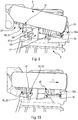
- the quick fixing device which will be described here differs from the first embodiment described above in particular by the arrangement of the locking interface 13 'projecting from the second face 11 of the support plate 8 (visible on the figure 6 ) and by the corresponding arrangement of the second snap-fastening part 25 '(visible on the Figures 7 and 8 ) carried on the outer wall of the second front end 15 of the body 6 for conveying fluid, it being understood that as before, the locking interface 13 ′ is capable of cooperating with said second portion 25 ′ of snap-fastening.
- the first positioning and orientation interface 12 remains identical here from the first to the second embodiment.
- the locking interface 13 'again forms a frame delimiting therein an opening 13a' for receiving the second fixing part 25 '.
- the interface here comprises a first rear transverse upright 50, a second opposite transverse upright 53 and a symmetrical pair of lateral uprights 55.
- the first rear transverse upright 50 which carries the latching means.
- only a single latching means 51 is provided.
- the second transverse upright 53 which has at its transverse ends a symmetrical pair of elements stop 54, which extend and widen the lateral uprights 55 forwards.
- the second front transverse upright 53 is here partially hollowed out at its center. This recess facilitates the positioning of the body 6 while allowing a saving of material.
- the abutment elements 54 and the lateral uprights 55 have upper faces inclined at an angle alpha ( ⁇ ), less than or equal to 25 °, in particular between 10 and 25 °. relative to a plane defined by the support plate 8, so as to allow, in the assembly position, an optimal inclination of the body 6 for conveying fluid and therefore of the distribution element 7 relative to the optical surface 4.
- the angle alpha ( ⁇ ) is for example equal to 15 ° as illustrated.
- the fastening means 23 ′ by latching carried by the interface 13 ′ for locking the support plate 8 consist of the latching means 51.
- the latching means 51 protrudes from the front edge of the first rear transverse upright 50 so as to extend into the opening formed in the center of the frame of the locking interface 13 'and it has the form of a partially annular projection which delimits in its center a central orifice 52, here of circular shape.
- the second part 25 'of snap fastening comprises complementary fastening means 57 by snap fastening, intended to cooperate with the snap means 51 of the locking interface 13', and legs 58 which project from the conveying body 6, transversely on either side of the complementary fixing means 57, these legs 58 being able to cooperate simultaneously with the abutment elements 54 of the locking interface 13 'and with the lateral uprights 55 of this locking interface.
- the complementary means 57 form complementary snap fastening means able to cooperate with the fastening means 23 'by snap carried by the locking interface 13' secured to the support plate.
- the complementary fixing means 57 comprise a flexible tongue 59, which has at its free end a latching head 60, as well as a reinforcing bar 61, the height of which is dimensioned moreover to form a stop against the first transverse upright. 50 back.
- the latching head 60 has an angular portion complementary to that of the central orifice 52 of the latching means 51, and it has an inclined plane on a face opposite to the conveying body 6 and a straight plane on the other face so as to be able to be elastically deformed to pass inside of the central orifice then resume its original shape and lock in position the routing body relative to the support plate 8.
- the flexible tongue 59 is able to deform elastically in the direction of the bar reinforcement 61 to allow the insertion of complementary fixing means 57 in the corresponding central orifice 52.
- the legs 58 have a large portion forming a first positioning leg 63, intended to cooperate with a lateral upright 55 of the locking interface 13 ′, and a small portion forming a second positioning leg 64 capable of coming resting on a stop element 54 of the locking interface 13 '.
- each first leg 63 may have at its free end a bevelled part forming an insertion ramp to facilitate the passage of the first legs inside the opening of the frame formed by the locking interface 13 'when the routing body is tilted to the assembly position. In this position, it is understood that the first legs bear against the internal face of the lateral uprights bordering the opening of the frame and that the second legs are supported on the upper face of the front transverse upright.
- the figures 9, 10 , 11 and 12 illustrate the steps of the method for mounting the device 100 for rapid fixing according to the second embodiment and in particular making visible the pre-assembly and assembly positions of the body 6 for conveying cleaning and / or drying fluid relative to to the support plate 8.
- the mounting method comprises, up to the final assembly step by locking, steps common to the two embodiments previously described.
- the first step consists in positioning the first guide part 24 of the body 6 for conveying fluid with respect to the positioning and orientation interface 12 projecting from the second face 11 of the support plate 8.
- This step ( visible on the figure 9 ) consists in particular in positioning the cylindrical pins 36 of the first guide portion 24 at the entrance to the guide slide in the corresponding position 20 provided on the positioning and orientation interface 12 of the support plate 8.
- the second step consists in tilting the body 6 for conveying fluid in a pre-assembly position (visible on the figure 10 ), to support the transverse tooth 37 integral with the body 6 for conveying fluid on the second transverse front wall 17 of the support plate 8.
- the height of this tooth 37 is configured so that, in the position of pre- assembly, the cylindrical pins 36 can be introduced into their corresponding slide 20, passing under the rim 20a.
- the third step consists in translating the body 6 for conveying fluid towards the rear of the support plate 8 in a stop position.
- This step (visible on the figure 11 ) more precisely consists in translating the pins 36 by linear sliding inside the corresponding slide 20 until the rear transverse branch 35 of the first guide portion 24 of the body 6 for conveying fluid comes into abutment against the central stop rod 21 secured to the positioning and orientation interface 12 of the support plate 8, so that inside each slide, the pins 36 are housed in the seat of complementary cylindrical shape formed by the bottom wall 20b.
- the snap-fastening means carried by the second part 25 'for fixing the conveying body 6 and by the locking interface 13' of the support plate 8, are placed opposite one another.
- the fourth step consists in carrying out a rotation of the body 6 for conveying fluid, around the axis of rotation Y defined by the cooperation of the cylindrical pins 36 in the corresponding seat formed by the bottom wall 20b of the slide 20, to cause the locking interface 13 ′ of the support plate 8 to cooperate with the second snap-fastening part 25 ′ of the body 6 for conveying fluid and to cause the body 6 of transport and the support plate 8 to take a final assembly position.
- the lugs 19, 39 produced in a complementary manner on the walls and lateral branches of the interface of positioning and the first guide part, allow the position of the assembly to be held, by tight adjustment.
- the final step of latching locking differs according to whether the quick fixing device conforms to the first or to the second embodiment of the invention.
- the figure 5 illustrates the final assembly position of the quick fixing device 100 according to the first embodiment of the invention where the second fixing part 25 cooperates with the locking interface 13 of the support plate 8.
- first complementary lateral locking means 42 and the second complementary transverse locking means 41 are engaged on the first 32 and second 30 locking means forming the fixing means 23 of the locking interface 13.
- the quick fixing device 100 allows according to the invention to achieve a reliable fixing by snap whatever the direction of the force applied to the fluid distribution element 7.
- the symmetrical pair of stops 40 of the second fixing part 25 is in abutment on the stop elements 28 of the locking interface 13 whose upper faces are inclined at an angle alpha ( ⁇ ) less than or equal to 25 °, in particular between 10 and 25 °, and in particular equal to 15 °, with respect to a plane defining the support plate 8, also carrying the optical sensor 2.
- ⁇ angle alpha
- the figure 12 illustrates the final assembly position of the quick fixing device 100 according to the second embodiment of the invention where the second fixing part 25 'of the body 6 for conveying fluid cooperates with the locking interface 13 ′ of the support plate 8.
- the complementary fixing means 57 are engaged with the latching means 51 forming the fixing means 23 'by latching of the locking interface 13'.
- the rotation generated around the axis of rotation Y in this final locking step is allowed by the elastic deformation of the flexible tongue 59 in contact with the wall delimiting the central orifice 52 arranged in through the opening of the locking interface 13 ′, this wall being bevelled inwards to facilitate guiding the tab in the central orifice, the flexible tab 59 then preventing the vertical disengagement of the routing body 6 with respect to this locking interface 13.
- the angular bearing of this flexible tongue 59 makes it possible to achieve reliable fixing by snap-in whatever the direction of the force applied to the fluid distribution element 7.
- the second positioning legs 64 are supported on the abutment elements 28 of the locking interface 13 'whose upper faces are inclined, from front to rear, by a angle alpha ( ⁇ ), less than or equal to 25 °, in particular between 10 and 25 °, for example equal to 15 °, with respect to a plane defining the support plate 8, also carrying the optical sensor 2. From the so, it is possible to ensure the position of the body 6 for conveying fluid and to ensure that the deployment of the dispensing element 7 which is attached to it allows a projection of cleaning fluid onto the optical surface 4 with a desired projection angle.
- ⁇ angle alpha
Applications Claiming Priority (1)
| Application Number | Priority Date | Filing Date | Title |
|---|---|---|---|
| FR1755707A FR3067995B1 (fr) | 2017-06-22 | 2017-06-22 | Platine de support de capteur optique, corps d'acheminement d'un dispositif de nettoyage telescopique de ce capteur optique, et dispositif de fixation rapide par encliquetage de ces composants |
Publications (3)
| Publication Number | Publication Date |
|---|---|
| EP3418134A2 EP3418134A2 (fr) | 2018-12-26 |
| EP3418134A3 EP3418134A3 (fr) | 2019-02-27 |
| EP3418134B1 true EP3418134B1 (fr) | 2020-07-08 |
Family
ID=59579759
Family Applications (1)
| Application Number | Title | Priority Date | Filing Date |
|---|---|---|---|
| EP18176662.7A Active EP3418134B1 (fr) | 2017-06-22 | 2018-06-08 | Platine de support de capteur optique, corps d'acheminement d'un dispositif de nettoyage télescopique de ce capteur optique, et ensemble de ces composants |
Country Status (6)
| Country | Link |
|---|---|
| US (1) | US10988118B2 (zh) |
| EP (1) | EP3418134B1 (zh) |
| JP (1) | JP2019038522A (zh) |
| KR (1) | KR102496983B1 (zh) |
| CN (1) | CN109109823B (zh) |
| FR (1) | FR3067995B1 (zh) |
Families Citing this family (7)
| Publication number | Priority date | Publication date | Assignee | Title |
|---|---|---|---|---|
| WO2020153115A1 (ja) * | 2019-01-25 | 2020-07-30 | トヨタ自動車株式会社 | 車両用クリーナ |
| FR3096001B1 (fr) * | 2019-05-17 | 2022-04-15 | A Raymond Et Cie | Agencement de montage d’un système optique sur un élément de carrosserie d’un véhicule |
| JP7188361B2 (ja) * | 2019-11-15 | 2022-12-13 | トヨタ自動車株式会社 | 車両前部構造 |
| CN112606774B (zh) * | 2020-12-28 | 2023-01-31 | 广东科学技术职业学院 | 一种可自清洁激光雷达的无人驾驶车辆 |
| FR3123280B1 (fr) * | 2021-05-29 | 2024-04-19 | Valeo Systemes Dessuyage | Dispositif de nettoyage télescopique, système de détection et procédé d’assemblage du dispositif de nettoyage télescopique |
| CN114056243B (zh) * | 2021-11-15 | 2024-03-22 | 天津津航技术物理研究所 | 一种光电探测设备的推出装置 |
| CN113844379A (zh) * | 2021-12-01 | 2021-12-28 | 枣庄智博智能科技有限公司 | 一种排除障碍物提高效率的多角度汽车雷达组件 |
Family Cites Families (17)
| Publication number | Priority date | Publication date | Assignee | Title |
|---|---|---|---|---|
| JP2009083714A (ja) * | 2007-10-01 | 2009-04-23 | Koito Mfg Co Ltd | 車輌用灯具の洗浄装置 |
| JP5056919B2 (ja) * | 2009-09-29 | 2012-10-24 | 株式会社デンソー | 車載光学センサカバー及び車載光学センサ装置 |
| US8671504B2 (en) * | 2010-04-28 | 2014-03-18 | Denso Corporation | Cover of vehicle optical sensor and vehicle optical sensor device |
| US20110292212A1 (en) * | 2010-05-27 | 2011-12-01 | Asmo Co., Ltd. | Washer nozzle for vehicle mounted camera, vehicle mounted camera, and washer device for vehicle |
| WO2014017405A1 (ja) * | 2012-07-27 | 2014-01-30 | 日産自動車株式会社 | 車載カメラ装置 |
| US9862321B2 (en) * | 2012-08-29 | 2018-01-09 | Smr Patents S.A.R.L. | Telescoping rearview assembly with camera and lens wiping system |
| US10155484B2 (en) * | 2012-08-29 | 2018-12-18 | Smr Patents S.A.R.L. | Telescoping rearview assembly with camera and lens wiping system |
| JP6379665B2 (ja) * | 2013-08-12 | 2018-08-29 | 株式会社デンソー | 車載光学センサ洗浄装置 |
| FR3027007B1 (fr) * | 2014-10-10 | 2017-12-08 | Valeo Systemes Dessuyage | Dispositif de nettoyage d’une camera d’aide a la conduite d’un vehicule automobile |
| DE102014118220A1 (de) * | 2014-12-09 | 2016-06-09 | Huf Hülsbeck & Fürst Gmbh & Co. Kg | Kameraanordnung eines Kraftfahrzeuges |
| CN204452373U (zh) * | 2015-02-02 | 2015-07-08 | 温岭市鑫凯汽车零部件有限公司 | 一种汽车洗涤器水壶加注管 |
| US20160272163A1 (en) * | 2015-03-17 | 2016-09-22 | Magna Electronics Inc. | Vehicle camera with lens washer system |
| DE102015005670B4 (de) * | 2015-05-02 | 2022-06-09 | Audi Ag | Reinigungsvorrichtung und Kraftfahrzeug mit einer Reinigungsvorrichtung |
| US10252703B2 (en) * | 2015-05-20 | 2019-04-09 | Denso Corporation | System for cleaning on-vehicle optical sensor and method for the same |
| FR3039113B1 (fr) * | 2015-07-22 | 2017-07-28 | Valeo Systemes Dessuyage | Dispositif de nettoyage d'un capteur pour vehicule automobile |
| KR101714180B1 (ko) * | 2015-07-28 | 2017-03-08 | 현대자동차주식회사 | 자동차용 헤드램프 워셔 커버 장치 |
| FR3040953B1 (fr) * | 2015-09-14 | 2018-08-17 | Valeo Systemes D'essuyage | Dispositif de nettoyage d'un systeme de detection equipant un vehicule automobile |
-
2017
- 2017-06-22 FR FR1755707A patent/FR3067995B1/fr active Active
-
2018
- 2018-06-08 EP EP18176662.7A patent/EP3418134B1/fr active Active
- 2018-06-21 US US16/014,457 patent/US10988118B2/en active Active
- 2018-06-21 JP JP2018117886A patent/JP2019038522A/ja active Pending
- 2018-06-22 KR KR1020180072247A patent/KR102496983B1/ko active IP Right Grant
- 2018-06-22 CN CN201810651532.XA patent/CN109109823B/zh active Active
Non-Patent Citations (1)
| Title |
|---|
| None * |
Also Published As
| Publication number | Publication date |
|---|---|
| EP3418134A3 (fr) | 2019-02-27 |
| KR20190000323A (ko) | 2019-01-02 |
| JP2019038522A (ja) | 2019-03-14 |
| CN109109823A (zh) | 2019-01-01 |
| FR3067995A1 (fr) | 2018-12-28 |
| EP3418134A2 (fr) | 2018-12-26 |
| US20180370499A1 (en) | 2018-12-27 |
| CN109109823B (zh) | 2021-10-08 |
| FR3067995B1 (fr) | 2021-03-19 |
| US10988118B2 (en) | 2021-04-27 |
| KR102496983B1 (ko) | 2023-02-06 |
Similar Documents
| Publication | Publication Date | Title |
|---|---|---|
| EP3418134B1 (fr) | Platine de support de capteur optique, corps d'acheminement d'un dispositif de nettoyage télescopique de ce capteur optique, et ensemble de ces composants | |
| EP3519260B1 (fr) | Dispositif de nettoyage destine a projeter au moins un fluide vers une surface a nettoyer d'un vehicule automobile | |
| EP1544035B1 (fr) | Ensemble de partie avant de véhicule automobile comportant des moyens perfectionnés de fixation et d'ajustement en position, et véhicule automobile pourvu d'un tel ensemble | |
| FR2910412A1 (fr) | Ensemble d'un support d'organe de detection ou d'eclairage d'un vehicule automobile et d'une grille de vehicule automobile, grille, support et organe de detection ou d'eclairage | |
| EP4072909A1 (fr) | Système de nettoyage d'un capteur/émetteur d'un véhicule automobile | |
| FR2857645A1 (fr) | Bloc projecteur pour vehicule automobile, et vehicule correspondant. | |
| WO2020136036A1 (fr) | Buse de projection de fluide pour dispositif de nettoyage d'un systeme de detection optique | |
| FR2796494A1 (fr) | Dispositif de fixation d'une batterie d'accumulateurs | |
| FR3037901A1 (fr) | Adaptateur pour relier un balai d'essuie-glace a un bras d'entrainement | |
| EP3519261B1 (fr) | Dispositif de nettoyage, destiné à projeter au moins un fluide vers une surface à nettoyer d'un véhicule automobile, tel qu'une surface optique d'un capteur d'un système de détection optique | |
| EP3554899A1 (fr) | Dispositif de connexion pour la liaison d'un balai d'essuyage a un bras d'entrainement pour vehicule | |
| EP3980300A1 (fr) | Dispositif de nettoyage d'une surface vitrée d'un capteur optique pour un véhicule automobile | |
| FR2953485A1 (fr) | Systeme de fixation d'un mobilier sur un plancher de vehicule de transport | |
| FR3013288A1 (fr) | Balai d'essuie-glace d'une vitre d'un vehicule | |
| FR3061562A1 (fr) | Dispositif de raccordement amovible pour un guide de lumiere et application dans un vehicule automobile, module a transmission optique pourvu du dispositif | |
| EP3366531B1 (fr) | Embout d'extremite adaptable pour balai d'essuyage | |
| FR3055861B1 (fr) | Adaptateur pour la connexion d'un balai d'essuyage a un bras d'entrainement d'un systeme d'essuyage pour vehicule automobile | |
| FR3091222A1 (fr) | Couvercle pour obturer une ouverture dans une paroi | |
| WO2024046925A1 (fr) | Connecteur d'un système d'essuyage. | |
| FR3055860A1 (fr) | Adaptateur constitutif d'un systeme d'essuyage | |
| WO2024061990A1 (fr) | Dispositif de nettoyage comprenant des buses | |
| FR3138393A1 (fr) | ensemble de nettoyage pour capteurs de véhicule automobile | |
| FR2971466A1 (fr) | Dispositif de montage et demontage simplifies d'au moins un projecteur de vehicule automobile | |
| FR3115006A1 (fr) | Support de fixation d’un capteur optique sur une surface vitrée d’un véhicule. | |
| FR3139734A1 (fr) | Buse de projection d’un dispositif de projection |
Legal Events
| Date | Code | Title | Description |
|---|---|---|---|
| PUAI | Public reference made under article 153(3) epc to a published international application that has entered the european phase |
Free format text: ORIGINAL CODE: 0009012 |
|
| STAA | Information on the status of an ep patent application or granted ep patent |
Free format text: STATUS: REQUEST FOR EXAMINATION WAS MADE |
|
| 17P | Request for examination filed |
Effective date: 20180608 |
|
| AK | Designated contracting states |
Kind code of ref document: A2 Designated state(s): AL AT BE BG CH CY CZ DE DK EE ES FI FR GB GR HR HU IE IS IT LI LT LU LV MC MK MT NL NO PL PT RO RS SE SI SK SM TR |
|
| AX | Request for extension of the european patent |
Extension state: BA ME |
|
| PUAL | Search report despatched |
Free format text: ORIGINAL CODE: 0009013 |
|
| AK | Designated contracting states |
Kind code of ref document: A3 Designated state(s): AL AT BE BG CH CY CZ DE DK EE ES FI FR GB GR HR HU IE IS IT LI LT LU LV MC MK MT NL NO PL PT RO RS SE SI SK SM TR |
|
| AX | Request for extension of the european patent |
Extension state: BA ME |
|
| RIC1 | Information provided on ipc code assigned before grant |
Ipc: B60S 1/56 20060101AFI20190124BHEP Ipc: G02B 27/00 20060101ALI20190124BHEP Ipc: B60S 1/52 20060101ALI20190124BHEP |
|
| GRAP | Despatch of communication of intention to grant a patent |
Free format text: ORIGINAL CODE: EPIDOSNIGR1 |
|
| STAA | Information on the status of an ep patent application or granted ep patent |
Free format text: STATUS: GRANT OF PATENT IS INTENDED |
|
| INTG | Intention to grant announced |
Effective date: 20200221 |
|
| GRAS | Grant fee paid |
Free format text: ORIGINAL CODE: EPIDOSNIGR3 |
|
| GRAA | (expected) grant |
Free format text: ORIGINAL CODE: 0009210 |
|
| STAA | Information on the status of an ep patent application or granted ep patent |
Free format text: STATUS: THE PATENT HAS BEEN GRANTED |
|
| AK | Designated contracting states |
Kind code of ref document: B1 Designated state(s): AL AT BE BG CH CY CZ DE DK EE ES FI FR GB GR HR HU IE IS IT LI LT LU LV MC MK MT NL NO PL PT RO RS SE SI SK SM TR |
|
| REG | Reference to a national code |
Ref country code: CH Ref legal event code: EP Ref country code: AT Ref legal event code: REF Ref document number: 1288115 Country of ref document: AT Kind code of ref document: T Effective date: 20200715 |
|
| REG | Reference to a national code |
Ref country code: DE Ref legal event code: R096 Ref document number: 602018005826 Country of ref document: DE |
|
| REG | Reference to a national code |
Ref country code: IE Ref legal event code: FG4D Free format text: LANGUAGE OF EP DOCUMENT: FRENCH |
|
| REG | Reference to a national code |
Ref country code: LT Ref legal event code: MG4D |
|
| REG | Reference to a national code |
Ref country code: AT Ref legal event code: MK05 Ref document number: 1288115 Country of ref document: AT Kind code of ref document: T Effective date: 20200708 |
|
| REG | Reference to a national code |
Ref country code: NL Ref legal event code: MP Effective date: 20200708 |
|
| PG25 | Lapsed in a contracting state [announced via postgrant information from national office to epo] |
Ref country code: ES Free format text: LAPSE BECAUSE OF FAILURE TO SUBMIT A TRANSLATION OF THE DESCRIPTION OR TO PAY THE FEE WITHIN THE PRESCRIBED TIME-LIMIT Effective date: 20200708 Ref country code: LT Free format text: LAPSE BECAUSE OF FAILURE TO SUBMIT A TRANSLATION OF THE DESCRIPTION OR TO PAY THE FEE WITHIN THE PRESCRIBED TIME-LIMIT Effective date: 20200708 Ref country code: PT Free format text: LAPSE BECAUSE OF FAILURE TO SUBMIT A TRANSLATION OF THE DESCRIPTION OR TO PAY THE FEE WITHIN THE PRESCRIBED TIME-LIMIT Effective date: 20201109 Ref country code: BG Free format text: LAPSE BECAUSE OF FAILURE TO SUBMIT A TRANSLATION OF THE DESCRIPTION OR TO PAY THE FEE WITHIN THE PRESCRIBED TIME-LIMIT Effective date: 20201008 Ref country code: SE Free format text: LAPSE BECAUSE OF FAILURE TO SUBMIT A TRANSLATION OF THE DESCRIPTION OR TO PAY THE FEE WITHIN THE PRESCRIBED TIME-LIMIT Effective date: 20200708 Ref country code: AT Free format text: LAPSE BECAUSE OF FAILURE TO SUBMIT A TRANSLATION OF THE DESCRIPTION OR TO PAY THE FEE WITHIN THE PRESCRIBED TIME-LIMIT Effective date: 20200708 Ref country code: NO Free format text: LAPSE BECAUSE OF FAILURE TO SUBMIT A TRANSLATION OF THE DESCRIPTION OR TO PAY THE FEE WITHIN THE PRESCRIBED TIME-LIMIT Effective date: 20201008 Ref country code: GR Free format text: LAPSE BECAUSE OF FAILURE TO SUBMIT A TRANSLATION OF THE DESCRIPTION OR TO PAY THE FEE WITHIN THE PRESCRIBED TIME-LIMIT Effective date: 20201009 Ref country code: HR Free format text: LAPSE BECAUSE OF FAILURE TO SUBMIT A TRANSLATION OF THE DESCRIPTION OR TO PAY THE FEE WITHIN THE PRESCRIBED TIME-LIMIT Effective date: 20200708 Ref country code: FI Free format text: LAPSE BECAUSE OF FAILURE TO SUBMIT A TRANSLATION OF THE DESCRIPTION OR TO PAY THE FEE WITHIN THE PRESCRIBED TIME-LIMIT Effective date: 20200708 |
|
| PG25 | Lapsed in a contracting state [announced via postgrant information from national office to epo] |
Ref country code: RS Free format text: LAPSE BECAUSE OF FAILURE TO SUBMIT A TRANSLATION OF THE DESCRIPTION OR TO PAY THE FEE WITHIN THE PRESCRIBED TIME-LIMIT Effective date: 20200708 Ref country code: LV Free format text: LAPSE BECAUSE OF FAILURE TO SUBMIT A TRANSLATION OF THE DESCRIPTION OR TO PAY THE FEE WITHIN THE PRESCRIBED TIME-LIMIT Effective date: 20200708 Ref country code: PL Free format text: LAPSE BECAUSE OF FAILURE TO SUBMIT A TRANSLATION OF THE DESCRIPTION OR TO PAY THE FEE WITHIN THE PRESCRIBED TIME-LIMIT Effective date: 20200708 Ref country code: IS Free format text: LAPSE BECAUSE OF FAILURE TO SUBMIT A TRANSLATION OF THE DESCRIPTION OR TO PAY THE FEE WITHIN THE PRESCRIBED TIME-LIMIT Effective date: 20201108 |
|
| PG25 | Lapsed in a contracting state [announced via postgrant information from national office to epo] |
Ref country code: NL Free format text: LAPSE BECAUSE OF FAILURE TO SUBMIT A TRANSLATION OF THE DESCRIPTION OR TO PAY THE FEE WITHIN THE PRESCRIBED TIME-LIMIT Effective date: 20200708 |
|
| REG | Reference to a national code |
Ref country code: DE Ref legal event code: R097 Ref document number: 602018005826 Country of ref document: DE |
|
| PG25 | Lapsed in a contracting state [announced via postgrant information from national office to epo] |
Ref country code: IT Free format text: LAPSE BECAUSE OF FAILURE TO SUBMIT A TRANSLATION OF THE DESCRIPTION OR TO PAY THE FEE WITHIN THE PRESCRIBED TIME-LIMIT Effective date: 20200708 Ref country code: SM Free format text: LAPSE BECAUSE OF FAILURE TO SUBMIT A TRANSLATION OF THE DESCRIPTION OR TO PAY THE FEE WITHIN THE PRESCRIBED TIME-LIMIT Effective date: 20200708 Ref country code: RO Free format text: LAPSE BECAUSE OF FAILURE TO SUBMIT A TRANSLATION OF THE DESCRIPTION OR TO PAY THE FEE WITHIN THE PRESCRIBED TIME-LIMIT Effective date: 20200708 Ref country code: DK Free format text: LAPSE BECAUSE OF FAILURE TO SUBMIT A TRANSLATION OF THE DESCRIPTION OR TO PAY THE FEE WITHIN THE PRESCRIBED TIME-LIMIT Effective date: 20200708 Ref country code: CZ Free format text: LAPSE BECAUSE OF FAILURE TO SUBMIT A TRANSLATION OF THE DESCRIPTION OR TO PAY THE FEE WITHIN THE PRESCRIBED TIME-LIMIT Effective date: 20200708 Ref country code: EE Free format text: LAPSE BECAUSE OF FAILURE TO SUBMIT A TRANSLATION OF THE DESCRIPTION OR TO PAY THE FEE WITHIN THE PRESCRIBED TIME-LIMIT Effective date: 20200708 |
|
| PLBE | No opposition filed within time limit |
Free format text: ORIGINAL CODE: 0009261 |
|
| STAA | Information on the status of an ep patent application or granted ep patent |
Free format text: STATUS: NO OPPOSITION FILED WITHIN TIME LIMIT |
|
| PG25 | Lapsed in a contracting state [announced via postgrant information from national office to epo] |
Ref country code: AL Free format text: LAPSE BECAUSE OF FAILURE TO SUBMIT A TRANSLATION OF THE DESCRIPTION OR TO PAY THE FEE WITHIN THE PRESCRIBED TIME-LIMIT Effective date: 20200708 |
|
| 26N | No opposition filed |
Effective date: 20210409 |
|
| PG25 | Lapsed in a contracting state [announced via postgrant information from national office to epo] |
Ref country code: SK Free format text: LAPSE BECAUSE OF FAILURE TO SUBMIT A TRANSLATION OF THE DESCRIPTION OR TO PAY THE FEE WITHIN THE PRESCRIBED TIME-LIMIT Effective date: 20200708 |
|
| PG25 | Lapsed in a contracting state [announced via postgrant information from national office to epo] |
Ref country code: SI Free format text: LAPSE BECAUSE OF FAILURE TO SUBMIT A TRANSLATION OF THE DESCRIPTION OR TO PAY THE FEE WITHIN THE PRESCRIBED TIME-LIMIT Effective date: 20200708 |
|
| PG25 | Lapsed in a contracting state [announced via postgrant information from national office to epo] |
Ref country code: MC Free format text: LAPSE BECAUSE OF FAILURE TO SUBMIT A TRANSLATION OF THE DESCRIPTION OR TO PAY THE FEE WITHIN THE PRESCRIBED TIME-LIMIT Effective date: 20200708 |
|
| REG | Reference to a national code |
Ref country code: CH Ref legal event code: PL |
|
| REG | Reference to a national code |
Ref country code: BE Ref legal event code: MM Effective date: 20210630 |
|
| PG25 | Lapsed in a contracting state [announced via postgrant information from national office to epo] |
Ref country code: LU Free format text: LAPSE BECAUSE OF NON-PAYMENT OF DUE FEES Effective date: 20210608 |
|
| PG25 | Lapsed in a contracting state [announced via postgrant information from national office to epo] |
Ref country code: LI Free format text: LAPSE BECAUSE OF NON-PAYMENT OF DUE FEES Effective date: 20210630 Ref country code: IE Free format text: LAPSE BECAUSE OF NON-PAYMENT OF DUE FEES Effective date: 20210608 Ref country code: CH Free format text: LAPSE BECAUSE OF NON-PAYMENT OF DUE FEES Effective date: 20210630 |
|
| PG25 | Lapsed in a contracting state [announced via postgrant information from national office to epo] |
Ref country code: BE Free format text: LAPSE BECAUSE OF NON-PAYMENT OF DUE FEES Effective date: 20210630 |
|
| GBPC | Gb: european patent ceased through non-payment of renewal fee |
Effective date: 20220608 |
|
| PG25 | Lapsed in a contracting state [announced via postgrant information from national office to epo] |
Ref country code: GB Free format text: LAPSE BECAUSE OF NON-PAYMENT OF DUE FEES Effective date: 20220608 |
|
| PG25 | Lapsed in a contracting state [announced via postgrant information from national office to epo] |
Ref country code: CY Free format text: LAPSE BECAUSE OF FAILURE TO SUBMIT A TRANSLATION OF THE DESCRIPTION OR TO PAY THE FEE WITHIN THE PRESCRIBED TIME-LIMIT Effective date: 20200708 |
|
| P01 | Opt-out of the competence of the unified patent court (upc) registered |
Effective date: 20230528 |
|
| PG25 | Lapsed in a contracting state [announced via postgrant information from national office to epo] |
Ref country code: HU Free format text: LAPSE BECAUSE OF FAILURE TO SUBMIT A TRANSLATION OF THE DESCRIPTION OR TO PAY THE FEE WITHIN THE PRESCRIBED TIME-LIMIT; INVALID AB INITIO Effective date: 20180608 |
|
| PGFP | Annual fee paid to national office [announced via postgrant information from national office to epo] |
Ref country code: FR Payment date: 20230622 Year of fee payment: 6 Ref country code: DE Payment date: 20230613 Year of fee payment: 6 |
|
| PG25 | Lapsed in a contracting state [announced via postgrant information from national office to epo] |
Ref country code: MK Free format text: LAPSE BECAUSE OF FAILURE TO SUBMIT A TRANSLATION OF THE DESCRIPTION OR TO PAY THE FEE WITHIN THE PRESCRIBED TIME-LIMIT Effective date: 20200708 |