EP3418009B1 - Contact determination device, control device, contact determination system, contact determination method, and contact determination program - Google Patents
Contact determination device, control device, contact determination system, contact determination method, and contact determination program Download PDFInfo
- Publication number
- EP3418009B1 EP3418009B1 EP17752839.5A EP17752839A EP3418009B1 EP 3418009 B1 EP3418009 B1 EP 3418009B1 EP 17752839 A EP17752839 A EP 17752839A EP 3418009 B1 EP3418009 B1 EP 3418009B1
- Authority
- EP
- European Patent Office
- Prior art keywords
- contact
- information
- unit
- target
- control
- Prior art date
- Legal status (The legal status is an assumption and is not a legal conclusion. Google has not performed a legal analysis and makes no representation as to the accuracy of the status listed.)
- Active
Links
- 238000000034 method Methods 0.000 title claims description 13
- 230000033001 locomotion Effects 0.000 claims description 134
- 238000005259 measurement Methods 0.000 claims description 81
- 230000008859 change Effects 0.000 claims description 66
- 230000001144 postural effect Effects 0.000 claims description 35
- 230000001133 acceleration Effects 0.000 claims description 20
- 230000005389 magnetism Effects 0.000 claims description 7
- 238000012545 processing Methods 0.000 description 69
- 230000005684 electric field Effects 0.000 description 8
- 238000004891 communication Methods 0.000 description 7
- 238000001514 detection method Methods 0.000 description 7
- 230000006870 function Effects 0.000 description 7
- 238000010586 diagram Methods 0.000 description 6
- 230000015654 memory Effects 0.000 description 6
- 230000009471 action Effects 0.000 description 4
- 238000013459 approach Methods 0.000 description 3
- 230000006378 damage Effects 0.000 description 3
- 230000000694 effects Effects 0.000 description 3
- 239000004065 semiconductor Substances 0.000 description 3
- 210000000245 forearm Anatomy 0.000 description 2
- 230000006872 improvement Effects 0.000 description 2
- 230000010354 integration Effects 0.000 description 2
- 210000001699 lower leg Anatomy 0.000 description 2
- 210000000689 upper leg Anatomy 0.000 description 2
- 208000027418 Wounds and injury Diseases 0.000 description 1
- 210000001015 abdomen Anatomy 0.000 description 1
- 238000004458 analytical method Methods 0.000 description 1
- 210000000617 arm Anatomy 0.000 description 1
- 230000006866 deterioration Effects 0.000 description 1
- 238000005516 engineering process Methods 0.000 description 1
- 208000014674 injury Diseases 0.000 description 1
- 210000002414 leg Anatomy 0.000 description 1
- 238000004519 manufacturing process Methods 0.000 description 1
- 238000012986 modification Methods 0.000 description 1
- 230000004048 modification Effects 0.000 description 1
- 238000012544 monitoring process Methods 0.000 description 1
- 230000004044 response Effects 0.000 description 1
Images


Classifications
-
- B—PERFORMING OPERATIONS; TRANSPORTING
- B25—HAND TOOLS; PORTABLE POWER-DRIVEN TOOLS; MANIPULATORS
- B25J—MANIPULATORS; CHAMBERS PROVIDED WITH MANIPULATION DEVICES
- B25J19/00—Accessories fitted to manipulators, e.g. for monitoring, for viewing; Safety devices combined with or specially adapted for use in connection with manipulators
- B25J19/02—Sensing devices
-
- B—PERFORMING OPERATIONS; TRANSPORTING
- B25—HAND TOOLS; PORTABLE POWER-DRIVEN TOOLS; MANIPULATORS
- B25J—MANIPULATORS; CHAMBERS PROVIDED WITH MANIPULATION DEVICES
- B25J19/00—Accessories fitted to manipulators, e.g. for monitoring, for viewing; Safety devices combined with or specially adapted for use in connection with manipulators
- B25J19/06—Safety devices
-
- B—PERFORMING OPERATIONS; TRANSPORTING
- B25—HAND TOOLS; PORTABLE POWER-DRIVEN TOOLS; MANIPULATORS
- B25J—MANIPULATORS; CHAMBERS PROVIDED WITH MANIPULATION DEVICES
- B25J13/00—Controls for manipulators
- B25J13/08—Controls for manipulators by means of sensing devices, e.g. viewing or touching devices
- B25J13/081—Touching devices, e.g. pressure-sensitive
- B25J13/084—Tactile sensors
-
- B—PERFORMING OPERATIONS; TRANSPORTING
- B25—HAND TOOLS; PORTABLE POWER-DRIVEN TOOLS; MANIPULATORS
- B25J—MANIPULATORS; CHAMBERS PROVIDED WITH MANIPULATION DEVICES
- B25J9/00—Programme-controlled manipulators
- B25J9/16—Programme controls
- B25J9/1602—Programme controls characterised by the control system, structure, architecture
-
- B—PERFORMING OPERATIONS; TRANSPORTING
- B25—HAND TOOLS; PORTABLE POWER-DRIVEN TOOLS; MANIPULATORS
- B25J—MANIPULATORS; CHAMBERS PROVIDED WITH MANIPULATION DEVICES
- B25J9/00—Programme-controlled manipulators
- B25J9/16—Programme controls
- B25J9/1674—Programme controls characterised by safety, monitoring, diagnostic
- B25J9/1676—Avoiding collision or forbidden zones
-
- G—PHYSICS
- G06—COMPUTING; CALCULATING OR COUNTING
- G06T—IMAGE DATA PROCESSING OR GENERATION, IN GENERAL
- G06T7/00—Image analysis
- G06T7/70—Determining position or orientation of objects or cameras
- G06T7/73—Determining position or orientation of objects or cameras using feature-based methods
- G06T7/75—Determining position or orientation of objects or cameras using feature-based methods involving models
-
- G—PHYSICS
- G05—CONTROLLING; REGULATING
- G05B—CONTROL OR REGULATING SYSTEMS IN GENERAL; FUNCTIONAL ELEMENTS OF SUCH SYSTEMS; MONITORING OR TESTING ARRANGEMENTS FOR SUCH SYSTEMS OR ELEMENTS
- G05B2219/00—Program-control systems
- G05B2219/30—Nc systems
- G05B2219/39—Robotics, robotics to robotics hand
- G05B2219/39082—Collision, real time collision avoidance
-
- G—PHYSICS
- G05—CONTROLLING; REGULATING
- G05B—CONTROL OR REGULATING SYSTEMS IN GENERAL; FUNCTIONAL ELEMENTS OF SUCH SYSTEMS; MONITORING OR TESTING ARRANGEMENTS FOR SUCH SYSTEMS OR ELEMENTS
- G05B2219/00—Program-control systems
- G05B2219/30—Nc systems
- G05B2219/40—Robotics, robotics mapping to robotics vision
- G05B2219/40201—Detect contact, collision with human
-
- G—PHYSICS
- G06—COMPUTING; CALCULATING OR COUNTING
- G06T—IMAGE DATA PROCESSING OR GENERATION, IN GENERAL
- G06T2207/00—Indexing scheme for image analysis or image enhancement
- G06T2207/30—Subject of image; Context of image processing
- G06T2207/30196—Human being; Person
Definitions
- the present invention relates to a contact determination device determining a contact condition between a target person and a control target, a control device controlling the control target based on a determination result of such a contact determination device, a contact determination system including such a contact determination device, a contact determination method using such a contact determination device, and a contact determination program for realizing such a contact determination device.
- Patent Literature 1 discloses a system in which robots and one worker work in cooperation in production lines in a factory.
- a worker wears a motion capture device measuring a work movement and a pressure sensor measuring a pressure on a hand and carries out work. Then, the industrial robots are controlled based on a work movement of the worker and loads applied to components obtained from measured pressures.
- Patent Literature 2 discloses a control device of a drive body which can reduce damage to each of members caused due to a collision.
- the control device disclosed in Patent Literature 2 when it is detected that a hand of a robot has collided with an obstacle, the hand is moved such that damage to each of members caused due to the collision is reduced as much as possible.
- US 2009/171505 A1 discloses a control device for a robot arm which, if a human approach detection unit detects approach of a person, performs control according to the impact between the robot arm and the person, through an impact countermeasure motion control unit, by setting individual mechanical impedances for the respective joint portions of the robot arm on the basis of the movement of the person detected by a human movement detection unit.
- US 2015/158178 A1 discloses a method for controlling a robot, which is designed to be operated in a working mode, in which a part of the robot is moved at a speed at which there is a risk of injury to a person.
- the working mode is deactivated if a safety device detects that the person has entered an action region of the displaceable part.
- a sensor unit determines a position and a posture of the person while the person is outside the action region of the part.
- a prediction unit determines an action region of the person.
- a collision monitoring unit monitors whether the two action regions overlap.
- the present invention has been made in consideration of such circumstances, and a main object thereof is to provide a contact determination device which can contribute to improvement of safety by determining a contact condition between a control target such as an industrial robot, and a target person such as a worker based on an electrical change and a movement state of the worker.
- another object of the present invention is to provide a control device controlling a control target based on a determination result of the contact determination device according to the present invention.
- Another object of the present invention is to provide a contact determination system including the contact determination device according to the present invention.
- Another object of the present invention is to provide a contact determination method using the contact determination device according to the present invention.
- Another object of the present invention is to provide a contact determination program realizing the contact determination device according to the present invention.
- a contact determination device determines a contact condition between a target person and a control target.
- the contact determination device includes a state information acquiring unit that acquires at least one of positional information and postural information of the target person; a body model acquiring unit that acquires a body model related to a shape of the body of the target person; a movement computing unit that computes a movement state of a computation target part in the body of the target person based on at least one of the positional information and the postural information acquired by the state information acquiring unit, and the body model acquired by the body model acquiring unit; a change acquiring unit that acquires information regarding an electrical change; and a contact condition determining unit that determines a contact condition between the target person and the control target based on the information regarding an electrical change acquired by the change acquiring unit, and the movement state of the computation target part of the target person computed by the movement
- the contact determination device includes a measurement information acquiring unit that acquires measurement information indicating a measurement result of a wearable device worn by the target person.
- the state information acquiring unit acquires at least one of the positional information and the postural information of the target person based on the measurement information acquired by the measurement information acquiring unit.
- the state information acquiring unit computes at least one of the positional information and the postural information of the target person based on the measurement information acquired by the measurement information acquiring unit.
- the measurement information acquiring unit acquires at least one of a speed, an acceleration, an angular speed, an angular acceleration, a pressure, and a magnetism as the measurement information.
- the contact determination device further includes a body model calculating unit that calculates the body model related to a shape of the body of the target person based on at least one of the positional information and the postural information acquired by the state information acquiring unit, and a body model recording unit that records the body model calculated by the body model calculating unit.
- the body model acquiring unit acquires the body model from the body model recording unit.
- the contact condition determining unit has means for detecting contact between the target person and the control target based on the information regarding an electrical change acquired by the change acquiring unit, and means for identifying a contact part based on the movement state of the computation target part computed by the movement computing unit, when contact is detected.
- the contact determination device further includes means for determining an approaching condition between the target person and the control target based on the movement state computed by the movement computing unit.
- the change acquiring unit starts acquiring the information regarding an electrical change when the target person and the control target subjected to determination of the approaching condition therebetween are determined to have approached each other.
- the state information acquiring unit acquires at least one of the positional information and the postural information of a plurality of target persons.
- the contact condition determining unit identifies a target person that has come into contact.
- the change acquiring unit acquires at least one of a surface of the target person and a surface of the control target, or an electrical change in the vicinity thereof.
- the contact determination device further includes a control target control unit that outputs a control command to control the control target, based on the contact condition determined by the contact condition determining unit.
- control target control unit outputs a control command to continue a movement, to halt a movement, to reduce an output regarding a movement, or to perform a contact avoiding movement.
- a control device disclosed in this application includes an input unit that receives an input of a contact condition between the target person and the control target from the contact determination device, and a control target control unit that outputs a control command to control the control target based on the contact condition received by the input unit.
- control target control unit outputs a control command to continue a movement, to halt a movement, to reduce an output regarding a movement, or to perform a contact avoiding movement.
- a contact determination system disclosed in this application includes a control target that moves based on control, and the contact determination device that determines a contact condition.
- the contact determination device includes a control target movement information acquiring unit which acquires control target movement information related to a movement of the control target.
- the contact condition determining unit determines a contact condition based on the control target movement information acquired by the control target movement information acquiring unit.
- the contact determination device includes a control target control unit which outputs a control command to control the control target based on the contact condition determined by the contact condition determining unit.
- the contact determination system further includes a control device that controls the control target.
- the control device includes an input unit which receives an input of a contact condition from the contact determination device, and a control target control unit which outputs a control command to control the control target based on the contact condition received by the input unit.
- a contact determination method disclosed in this application is used for determining a contact condition between a target person and a control target.
- the contact determination method includes a step in which a state information acquiring unit acquires at least one of positional information and postural information of the target person; a step in which a body model acquiring unit acquires a body model related to a shape of the body of the target person; a step in which a movement computing unit computes a movement state of a computation target part in the body of the target person based on at least one of the positional information and the postural information acquired by the state information acquiring unit, and the body model acquired by the body model acquiring unit; a step in which a change acquiring unit acquires information regarding an electrical change; and a step in which a contact condition determining unit determines a contact condition between the target person and the control target based on the information regarding an electrical change acquired by the change acquiring unit, and the movement state of the computation target part of the target person computed by the movement computing unit.
- a step is performed in which a measurement information acquiring unit acquires measurement information indicating a measurement result of a wearable device worn by the target person, wherein the state information acquiring unit acquires at least one of the positional information and the postural information of the target person based on the measurement information acquired by the measurement information acquiring unit.
- a contact determination program disclosed in this application is used for causing a computer to determine a contact condition between a target person and a control target.
- the contact determination program causes the computer to execute a step of acquiring at least one of positional information and postural information of the target person; a step of acquiring a body model related to a shape of the body of the target person; a step of computing a movement state of a computation target part in the body of the target person based on at least one of the acquired positional information and postural information, and the acquired body model; a step of acquiring information regarding an electrical change; and a step of determining a contact condition between the target person and the control target based on the acquired information regarding an electrical change and the computed movement state of the computation target part of the target person.
- a step is performed of acquiring measurement information indicating a measurement result of a wearable device worn by the target person, wherein the step of acquiring at least one of positional information and postural information of the target person comprises acquiring at least one of the positional information and the postural information of the target person based on the measurement information acquired by the step of acquiring measurement information indicating a measurement result of the wearable device worn by the target person.
- the contact determination device, the control device, the contact determination system, the contact determination method, and the contact determination program disclosed in this application can determine a contact condition between a target person and a control target based on an electrical change and a movement state of the target person.
- a contact condition between a target person and a control target for example, a contact part of a target person is determined based on a movement state of a computation target part computed based on positional information and/or postural information of a measurement target part, and a body model of the target person; and an electrical change. Accordingly, the present invention exhibits an excellent effect. For example, it is possible to contribute to improvement of safety in controlling a control target, or the like based on a determined contact condition.
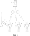
- Fig. 1 is a view for conceptually describing an example of the contact determination system disclosed in this application.
- the contact determination system disclosed in this application includes a working robot (which will hereinafter be referred to as a robot) 2 as a control target which works in response to a predetermined control command.
- the contact determination system is applied to a system such as a factory automation (FA) system in which a worker (target person) works in cooperation with the robot 2.
- FA factory automation
- the wearable devices 3 including various inertial sensors measure the measurement target parts of the body of a target person and output various pieces of measurement information indicating a measurement result.
- sensors installed in the wearable devices 3 it is possible to use sensors such as a magnetic sensor and a pressure sensor, in addition to inertial sensors such as an acceleration sensor and a gyro sensor.
- contact sensors (detection devices) 4 including sensors such as a voltage sensor, a current sensor, an electric field sensor, and an electromagnetic wave sensor for detecting, for contact, a change in electrical characteristics such as a voltage, a current, an electric field, and electromagnetic waves in the surroundings are provided in parts such as the hands of a worker.
- the sensors output a contact result based on a detected electrical change.
- each of the workers who become targets of impact estimation wears the wearable devices 3.
- Fig. 1 to facilitate understanding, in a worker wearing the wearable devices 3, parts, at which the inertial sensors are positioned, are indicated with white circles, and parts, at which the contact sensors 4 are positioned, are indicated with stippled white circles.
- illustration of the contact sensors 4 has priority.
- the contact determination system includes a contact determination device 1 which acquires various pieces of information output from the wearable devices 3 and the contact sensors 4 and determines a contact condition between a worker and the robot 2.
- the contact determination device 1 is constituted using a computer such as a control computer controlling the robot 2.
- the contact determination device 1 is indirectly or directly connected to the wearable devices 3, the contact sensors 4, and the robot 2 via a communication network such as a local area network (LAN) using a wireless or wired communication method to be able to communicate therewith.
- the contact determination device 1 performs communication of various pieces of information and signals.
- the robot 2 and the contact determination device 1 are disclosed as separate devices independent from each other.
- the contact determination device 1 may be a device built in the robot 2.
- a circuit or a program which functions as the contact determination device 1 may be built in a portion of a control circuit which controls movement of the robot 2.
- the contact determination device 1 may be built in each of the robots 2.
- Fig. 2A and Fig. 2B are views for conceptually describing another example of the contact determination system disclosed in this application.
- Fig. 2A and Fig. 2B illustrate different forms of disposition positions of the contact sensors 4 such as the voltage sensor, the current sensor, the electric field sensor, and the electromagnetic wave sensor in the contact determination system described using Fig. 1 .
- Fig. 2A illustrates a form in which the contact sensors 4 are disposed in an arm portion included in the robot 2
- Fig. 2B illustrates a form in which the contact sensors 4 are disposed in both the hands of a worker and the arm portion of the robot 2.
- the contact sensors 4 need only detect an electrical change between the robot 2 and a worker as contact targets and can be disposed at diverse places.
- Fig. 3 is a block diagram illustrating an example of a hardware configuration of the contact determination device 1 and other various devices included in the contact determination system disclosed in this application.
- the contact determination device 1 includes a control unit 10 and a recording unit 11. Moreover, as interfaces with respect to other devices, the contact determination device 1 includes a measurement information acquiring unit 12, a robot input/output unit 13, a contact information acquiring unit (change acquiring unit) 14, and an information input unit 15.
- the control unit 10 is constituted of a processor such as a central processing unit (CPU) and a memory such as a register.
- the control unit 10 controls the device in its entirety by executing various commands and outputs a control command to the robot 2.
- the recording unit 11 includes non-volatile memories such as a read only memory (ROM) and an erasable programmable read only memory (EPROM), a volatile memory such as a random access memory (RAM), and recording mediums such as a hard disk drive and a semiconductor memory.
- the recording unit 11 records data such as various programs and information.
- a contact determination program PG causing a computer such as a control computer to function as the contact determination device 1 according to the present invention is recorded in a recording domain of the recording unit 11.
- a portion in the recording domain of the recording unit 11 is used as a body model recording unit 11a for recording a body model schematizing the shape of the body of each worker.
- the body model denotes a digitized model which is schematized using numerical values of lengths and the like of various parts such as upper arms, forearms, femurs, and crura of the body of each worker.
- the body model related to each worker is recorded in association with worker identification information (worker's ID) identifying the worker.
- a recording device such as a server computer in which various pieces of information are recorded may be connected to the contact determination device 1, and a portion in a recording domain of the recording device connected to the contact determination device 1 may be used as database of the body model recording unit 11a and the like. That is, the body model recording unit 11a need only be in a state in which the control unit 10 included in the contact determination device 1 can have access thereto and can record and read data thereof.
- the body model recording unit 11a can be designed to have diverse forms.
- the measurement information acquiring unit 12 is an interface for acquiring various pieces of information such as measurement information indicating a measurement result from each of the wearable devices 3.
- the robot input/output unit 13 is an interface for acquiring various pieces of information from the robot 2 and outputting various commands.
- the contact information acquiring unit 14 is an interface for acquiring various pieces of information regarding an electrical change such as information indicating contact from the contact sensors 4.
- the information input unit 15 is an interface for communicating with various devices such as an information input device 5 used for inputting various pieces of information such as information indicating a body model.
- the interfaces are not necessarily present as independent devices and can be suitably used in common. On the other hand, it is possible to provide a plurality of devices for inputting and outputting different types of information with respect to one device.
- the configuration need only include one device to be connected to the communication network.
- the information input unit 15 may receive an input of a body model from the information input device 5 using a device such as a tablet computer and may receive an input of a body model from a portable recording medium such as various semiconductor memories.
- the information input unit 15 can be suitably designed.
- a computer such as a control computer functions as the contact determination device 1 by executing various steps such as reading various programs, for example, the contact determination program PG, recorded in the recording unit 11, acquiring state information (positional information and/or postural information) included in the read contact determination program PG, acquiring a body model, computing a movement state, acquiring information regarding an electrical change, and determining a contact condition, while being under control of the control unit 10.
- state information positional information and/or postural information
- the robot 2 includes various configurations such as the control unit 10 which controls the device in its entirety, a moving unit such as the arm portion which carries out work, a sensor unit which detects information of a posture and the like, and the input/output unit which communicates with the contact determination device 1.
- the control unit 10 which controls the device in its entirety
- a moving unit such as the arm portion which carries out work
- a sensor unit which detects information of a posture and the like
- the input/output unit which communicates with the contact determination device 1.
- the wearable devices 3 include various configurations such as a measurement unit using sensors (for example, an acceleration sensor and a gyro sensor) for detecting information related to a movement, and other output units.
- sensors installed in the wearable devices 3, it is possible to use sensors such as a magnetic sensor and a pressure sensor measuring physical quantities, in addition to an acceleration sensor and a gyro sensor.
- the measurement unit measures physical quantities such as a speed, an angular speed, an acceleration, an angular acceleration, a pressure, and a magnetism, and the output unit outputs a measurement result as measurement information (raw data or the like indicating a measurement result related to a movement of a worker) to the contact determination device 1.
- the contact determination device 1 acquires the state information such as the positional information and the postural information indicating the states of the measurement target parts calculated based on the measurement information indicating physical quantities such as a speed, an angular speed, an acceleration, an angular acceleration, a pressure, and a magnetism.
- the positional information can be calculated by integrating the acceleration measured by the acceleration sensor twice.
- the state information such as the positional information and the postural information calculated based on the measurement information indicating physical quantities such as a speed, an angular speed, an acceleration, an angular acceleration, a pressure, and a magnetism
- the state information may be computed by any of the wearable devices 3 and the contact determination device 1.
- the contact sensors 4 include various configurations such as sensors (for example, a voltage sensor, a current sensor, an electric field sensor, and an electromagnetic wave sensor) for detecting electrical characteristics, and an output unit.
- the output unit outputs information indicating contact such as contact between a worker and the robot 2 to the contact determination device 1 based on a change in electrical information such as a voltage, a current, an electric field, and electromagnetic waves indicating electrical characteristics detected by the sensors in the vicinity of a surface of a worker and/or a surface of the robot 2.
- Fig. 4 is a functional block diagram illustrating an example of a functional configuration of the contact determination device 1 and other various devices included in the contact determination system disclosed in this application.
- the contact determination device 1 executes various programs such as the contact determination program PG and realizes functions as computing units (for example, a state information acquiring unit 10a, a body model computing unit 10b, a body model acquiring unit 10c, a body movement computing unit (movement computing unit) 10d, a contact condition determining unit 10e, and a robot movement computing unit (control target control unit) 10f) executing various computations based on control of the control unit 10.
- Each of the diverse computing units realizing various functions can be mounted as a dedicated circuit using a semiconductor chip such as a large scale integration (LSI) and a very large scale integration (VLSI).
- LSI large scale integration
- VLSI very large scale integration
- the state information acquiring unit 10a acquires the state information of the measurement target parts, such as the positional information and the postural information through a computation based on the measurement information indicating physical quantities such as a speed, an angular speed, an acceleration, an angular acceleration, a pressure, and a magnetism acquired by the measurement information acquiring unit 12 from the wearable devices 3.
- the wearable devices 3 compute the state information such as the positional information and the postural information from the measurement information, and when the contact determination device 1 acquires the state information, the state information acquiring unit 10a acquires the acquired state information as it is, as information to be used in the computations thereafter.
- the body model computing unit 10b executes a computation of calculating a body model which is schematized data of the shape of the body of a worker, based on various pieces of state information such as the positional information and the postural information acquired by the state information acquiring unit 10a.
- a body model based on various pieces of state information based on measurements of the wearable devices 3 which a worker wears can be calculated using diverse technologies in the related art. For example, it is possible to apply the method disclosed in " Hiroshi KANASUGI, Ryosuke SHIBASAKI, Measurement and Analysis of Body Movement Using Wearable Sensor, Japan Society of Photogrammetry and Remote Sensing, Journal of JSPRS, 2005, pp.199-202, 2005.06 ".
- the body model acquiring unit 10c executes processing of acquiring the body model recorded in the body model recording unit 11a.
- the body movement computing unit 10d executes a computation of calculating the movement states of the computation target parts such as the hands and the legs in the body of a worker based on the state information acquired by the body model acquiring unit 10c and the body model acquired from the body model recording unit 11a by the body model acquiring unit 10c.
- the movement state is calculated as information such as positions of the computation target parts, a moving direction, an estimated position after a predetermined time, and an estimated moving direction.
- the contact condition determining unit 10e performs a computation for determining a contact condition whether or not a worker and the robot 2 are in contact with each other, based on an electrical change and the movement state of the computation target parts of a worker.
- An electrical change indicates a change in electrical characteristics such as a voltage, a current, an electric field, and electromagnetic waves detected by the contact sensors 4.
- an electrical change is output from the contact sensors 4 as information indicating contact, and the output information is acquired via the contact information acquiring unit 14.
- the contact sensors 4 may output electrical information such as a voltage, a current, an electric field, and an electromagnetic wave, or information indicating a change therein. In such a case, the contact condition determining unit 10e calculates the amount of the change and determines the presence of contact.
- the contact condition determining unit 10e can be designed such that occurrence of contact based on an electrical change can be acquired by diverse methods.
- the contact condition determining unit 10e determines whether or not a portion of the body of a worker, such as the computation target parts, and the robot 2 are in contact with each other. For example, the position and the movement state of the robot 2 are acquired from the robot movement computing unit 10f.
- the contact condition determining unit 10e also determines which worker is in contact. When the presence of contact is determined, the contact condition determining unit 10e executes processing for arbitrarily controlling the robot 2, as necessary.
- the robot movement computing unit 10f communicates with the robot 2 via the robot input/output unit 13 and executes outputting a control command to the robot 2, inputting a movement state from the robot 2, and processing of various computations and the like for controlling the robot 2.
- the robot movement computing unit 10f outputs the movement state of the robot 2 to the contact condition determining unit 10e, receives an input from the contact condition determining unit 10e based on contact between a worker and the robot 2, and outputs a control command for arbitrarily controlling the robot 2 to the robot 2.
- Examples of a control command output from the robot movement computing unit 10f to the robot 2 include control commands to continue a movement, to halt a movement, to reduce an output regarding a movement, and to perform a contact avoiding movement.
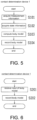
- Fig. 5 is a flow chart illustrating an example of first body model recording processing of the contact determination device 1 included in the contact determination system disclosed in this application.
- the first body model recording processing is processing in which a worker wearing the wearable devices 3 makes a movement, information based on the movement is acquired, and a body model computed from the acquired information is recorded in the body model recording unit 11a.
- the control unit 10 included in the contact determination device 1 executes the first body model recording processing by executing various programs such as the contact determination program PG.
- the control unit 10 of the contact determination device 1 causes the measurement information acquiring unit 12 to acquire measurement information from the wearable devices 3 which a worker is wearing (S101).
- Acquiring measurement information in Step S101 is processing in which the worker wearing various inertial sensors as the wearable devices 3 makes a predetermined reference movement, and the measurement information acquiring unit 12 acquires measurement information indicating at least one of physical quantities such as a speed, an angular speed, an acceleration, an angular acceleration, a pressure, and a magnetism of the measurement target parts measured in accordance with the reference movement made by the worker.
- the control unit 10 causes the state information acquiring unit 10a to acquire the state information such as the positional information and the postural information through a computation based on the measurement information acquired by the measurement information acquiring unit 12 (S102).
- Step S102 is processing in which at least one of the positional information and the postural information of the target person is computed as the state information based on the measurement information acquired by the measurement information acquiring unit 12 measuring a movement of the target person.
- the control unit 10 causes the body model computing unit 10b to perform a computation such that the body model which is schematized data of the shape of the body of the worker is calculated (computed) based on the acquired state information (S103).
- the control unit 10 causes the body model recording unit 11a to record the calculated body model in association with worker identification information identifying the worker that has made a movement (S104).
- Fig. 6 is a flow chart illustrating an example of second body model recording processing of the contact determination device 1 included in the contact determination system disclosed in this application.
- the second body model recording processing is processing in which a body model computed in advance is input to the contact determination device 1 from the information input device 5 in which the body model is recorded.
- the control unit 10 included in the contact determination device 1 executes the second body model recording processing by executing various programs such as the contact determination program PG.
- the control unit 10 of the contact determination device 1 causes the information input unit 15 to receive inputs of the body model and corresponding worker identification information from the information input device 5 connected to the contact determination device 1 (S201). Then, the control unit 10 records the received body model in association with the worker identification information in the body model recording unit 11a (S202).
- any of the first body model recording processing and the second body model recording processing may be used, and another method may be used.
- Fig. 7 is a flow chart illustrating an example of first contact determination processing of the contact determination device 1 included in the contact determination system disclosed in this application.
- the first contact determination processing is processing in which the contact condition between the robot 2 and a worker is determined based on the acquired electrical change and the body model recorded in the body model recording unit 11a through the first body model recording processing or the second body model recording processing.
- the contact sensors 4 are used in an activated state at all times, in which detection processing of detecting a change in electrical characteristics is continuously performed.
- the control unit 10 included in the contact determination device 1 executes the first contact determination processing by executing various programs such as the contact determination program PG.
- the control unit 10 of the contact determination device 1 starts acquiring contact information (S301).
- Step S301 processing in which the contact information acquiring unit 14 acquires an electrical change output by the contact sensors 4 or information indicating contact based on the electrical change starts.
- the control unit 10 executes processing of calculating the movement state of the worker and processing of acquiring the contact information in a manner of parallel processing. That is, as one part of the processing, the control unit 10 causes the measurement information acquiring unit 12 to acquire the measurement information (S302) and causes the state information acquiring unit 10a to acquire the state information based on the acquired measurement information (S303). Moreover, the control unit 10 causes the body model acquiring unit 10c to acquire the body model recorded in the body model recording unit 11a (S304). Then, the control unit 10 causes the body movement computing unit 10d to calculate the movement states of the computation target parts based on the state information and the body model which have been acquired (S305). The movement states of the computation target parts based on the measurement information are calculated for each worker.
- control unit 10 causes the contact information acquiring unit 14 to acquire information indicating contact based on an electrical change (S306).
- the control unit 10 causes the contact condition determining unit 10e to determine whether or not the target person and the control target are in contact with each other based on the information indicating contact based on the electrical change (S307).
- Step S307 when a change, in which information indicating electrical characteristics such as a voltage, a current, an electric field, and electromagnetic waves on a surface of a hand of the worker and/or a surface of an arm of the robot 2, or in the vicinity thereof detected by the contact sensors 4 exceeds a reference value set in advance, is detected, the worker and the robot 2 are determined to be in contact with each other.
- Step S304 when the worker and the robot 2 are determined not to be in contact with each other (S307: NO), the control unit 10 executes the parallel processing of the processing of calculating the movement state of the worker and the processing of acquiring the contact information again.
- Step S307 when the worker and the robot 2 are determined to be in contact with each other (S307: YES), the control unit 10 causes the contact condition determining unit 10e to determine the contact condition between the worker and the robot 2 (S308).
- the contact condition is determined based on the acquired movement states of the computation target parts of each worker, and the movement state of the robot 2 acquired from the robot movement computing unit 10f. For example, determination of the contact condition mentioned herein indicates identification of the worker in contact with the robot 2 and the contact part.
- Steps S307 to S308 the control unit 10 of the contact determination device 1 determines a contact condition between the worker and the robot 2 based on the acquired information regarding an electrical change and the computed movement states of the computation target parts of the worker.
- the control unit 10 which has determined the contact condition performs arbitrary control over the robot 2 by outputting a control command from the robot movement computing unit 10f to the robot 2 via the robot input/output unit 13 (S309).
- the arbitrary control in Step S309 denotes that predetermined control set in advance, such as continuing a movement, halting a movement, reducing an output regarding a movement, and performing a movement to avoid contact with the worker, as well as shifting to a safety mode and collecting information, is performed with respect to the robot 2 based on the contact condition determined in Step S308.
- the control unit 10 outputs a control command for performing arbitrary control to the robot 2.
- control unit 10 determines whether or not to end the contact determination processing (S310). For example, when the worker ends work and performs a predetermined operation to end the contact determination processing, the control unit 10 which has received the operation determines to end the contact determination processing.
- Step S310 when the contact determination processing is determined to end (S310: YES), the control unit 10 ends the contact determination processing. In Step S310, when the contact determination processing is determined not to end (S310: NO), the control unit 10 executes the parallel processing of the processing of calculating the movement state of the worker and the processing of acquiring the contact information again.
- the first contact determination processing is executed.
- the contact determination device 1 determines a contact condition such as the presence or absence of contact between a worker and the robot 2, a worker in contact, and the contact part of the worker based on an electrical change detected by the contact sensors 4 and a movement condition computed from the measurement information acquired from the wearable devices 3.
- arbitrary control of the robot 2 is appropriately performed in accordance with the determined contact condition. Accordingly, appropriate control can be performed in accordance with the contact condition. Consequently, the robot 2 is not excessively halted while safety of a worker is ensured. Therefore, it is possible to prevent unnecessary deterioration of productivity.
- Such an effect leads to realizing safe cooperation between the robot 2 and a worker even if the robot 2 and the worker are in circumstances not isolated by a safety fence.
- the information collected as a part of arbitrary control can be useful for various types of amelioration such as work amelioration and control amelioration in the future, and it is possible to expect further improved safety.
- Fig. 8 is a flow chart illustrating an example of second contact determination processing of the contact determination device 1 included in the contact determination system disclosed in this application.
- the second contact determination processing is a modification example of the first contact determination processing and is performed in a form in which the contact sensors 4 are not activated at all times but are activated when a possibility of contact is determined to be present.
- the control unit 10 included in the contact determination device 1 executes the second contact determination processing by executing various programs such as the contact determination program PG.
- the control unit 10 of the contact determination device 1 causes the measurement information acquiring unit 12 to acquire the measurement information (S401) and causes the state information acquiring unit 10a to acquire the state information based on the measurement information (S402).
- the control unit 10 causes the body model acquiring unit 10c to acquire the body model recorded in the body model recording unit 11a (S403).
- the control unit 10 causes the body movement computing unit 10d to calculate the movement states of the computation target parts based on the state information and the body model which have been acquired (S404).
- the control unit 10 determines whether or not there is a part of the worker approaching the robot 2, as an approaching condition based on the calculated movement states of the computation target parts of each worker and the movement state of the robot 2 acquired from the robot movement computing unit 10f (S405).
- Step S405 for example, the right hand, which is one of the computation target parts of the worker, is making a movement approaching the robot 2.
- the worker is determined to be in circumstances such as a case of approaching the reference value or lower and a case in which contact is expected within a reference time, it is determined that there is an approaching part.
- Step S405 when it is determined that there is a part approaching the robot 2 (S405: YES), the control unit 10 determines the approaching condition based on the movement state of each worker and the movement state of the robot 2 (S406). Determination of the approaching condition in Step S406 is identification of the worker approaching the robot 2 and identification the approaching part.
- Step S407 the contact sensors 4 are activated, and control is performed to start acquiring the contact information based on detection of an electrical change.
- the contact sensors 4 are already activated and are in an operation state, the operation state continues and the contact information is acquired.
- the control unit 10 causes the contact condition determining unit 10e to acquire the contact information based on an electrical change and determines whether or not the worker and the robot 2 are in contact with each other (S408). In Step S408, when it is determined that the worker and the robot 2 are not in contact with each other (S408: NO), the control unit 10 returns to Step S401 and repeats the processing thereafter.
- Step S408 when it is determined that the worker and the robot 2 are in contact with each other (S408: YES), the contact condition determining unit 10e is caused to determine the contact condition between the worker and the robot 2 (S409).
- the control unit 10, which has determined the contact condition, performs arbitrary control over the robot 2 by outputting a control command from the robot movement computing unit 10f to the robot 2 via the robot input/output unit 13 (S410).
- control unit 10 determines whether or not to end the contact determination processing (S411).
- Step S411 when it is determined to end the contact determination processing (S411: YES), the contact determination processing ends. In addition, operation of the contact sensors 4 and acquiring of the contact information also end. In Step S411, when it is determined not to end the contact determination processing (S411: NO), the control unit 10 returns to Step S401 and repeats the processing thereafter.
- Step S405 when it is determined that there is no part approaching the robot 2 (S405: NO), the control unit 10 determines whether or not the contact information is being acquired (S412). In Step S412, when it is determined that the contact information is being acquired (S412: YES), the control unit 10 ends operation of the contact sensors 4 and acquiring of the contact information (S413), returns to Step S401, and repeats the processing thereafter. In Step S412, when it is determined that the contact information is not being acquired (S412: NO), the control unit 10 returns to Step S401 and repeats the processing thereafter.
- the second contact determination processing is executed. Compared to the first determination processing, the second determination processing can save energy required to operate the contact sensors 4 and to acquire the contact information.
- control target which becomes a target of determination of contact or approaching a robot such as a working robot has been illustrated.
- targets such as a target repeating a predetermined movement, and a target in a restrained state can also be the control target which will become a target of determination and can be developed in diverse forms.
- the embodiment has been illustrated in a form in which the contact determination device 1 performs various computations using diverse computing units such as the body model computing unit 10b, the body movement computing unit 10d, and the robot movement computing unit 10f.
- the present invention is not limited thereto. That is, the present invention can be developed in various forms.
- a different device can include a portion of the computing functions.
- the contact determination device 1 can acquire results of various computations from the different device and can cause the contact condition determining unit 10e to execute a computation regarding determination of the contact condition.
- the embodiment has been illustrated in a form in which the contact determination device 1 controls the robot 2.
- the present invention is not limited thereto.
- the present invention can be developed in various forms. For example, separately from the contact determination device 1 determining the contact condition, a device for controlling the robot 2 can be provided.
- Fig. 9 is a functional block diagram illustrating an example of a functional configuration of various devices in another example of a system configuration of the contact determination system disclosed in this application.
- the control device 6 is formed using a device such as a control computer which controls the robot 2 and is connected to the contact determination device 1 and the robot 2.
- the contact determination device 1 includes a control device output unit 16 as a communication interface with respect to the control device 6.
- the control device 6 includes various configurations such as an input unit 60 which serves as a communication interface with respect to the contact determination device 1, and a control target control unit 61 which controls the robot 2.
- the contact determination device 1 outputs the contact condition determined by the contact condition determining unit 10e from the control device output unit 16 to the control device 6.
- the control device 6 receives an input of the contact condition from the input unit 60 and causes the control target control unit 61 to determine control over the robot 2 based on the contact condition.
- the control device 6 outputs a control command for arbitrarily controlling the robot 2 from the control target control unit 61 to the robot 2 based on the contact condition.
- a control command to be output to the robot 2 is a command to perform predetermined control set in advance with respect to the robot 2 such as continuing a movement, halting a movement, reducing an output regarding a movement, and performing a movement to avoid contact with a worker, as well as shifting to a safety mode and collecting information. That is, the control target control unit 61 included in the control device 6 realizes a function similar to that of the robot movement computing unit (control target control unit) 10f included in the contact determination device 1.
- the contact determination system disclosed in this application can be developed in diverse system configurations.
Landscapes
- Engineering & Computer Science (AREA)
- Robotics (AREA)
- Mechanical Engineering (AREA)
- Human Computer Interaction (AREA)
- Automation & Control Theory (AREA)
- Computer Vision & Pattern Recognition (AREA)
- Physics & Mathematics (AREA)
- General Physics & Mathematics (AREA)
- Theoretical Computer Science (AREA)
- Manipulator (AREA)
Applications Claiming Priority (2)
| Application Number | Priority Date | Filing Date | Title |
|---|---|---|---|
| JP2016025963A JP6481635B2 (ja) | 2016-02-15 | 2016-02-15 | 接触判定装置、制御装置、接触判定システム、接触判定方法及び接触判定プログラム |
| PCT/JP2017/000565 WO2017141575A1 (ja) | 2016-02-15 | 2017-01-11 | 接触判定装置、制御装置、接触判定システム、接触判定方法及び接触判定プログラム |
Publications (3)
| Publication Number | Publication Date |
|---|---|
| EP3418009A1 EP3418009A1 (en) | 2018-12-26 |
| EP3418009A4 EP3418009A4 (en) | 2019-10-09 |
| EP3418009B1 true EP3418009B1 (en) | 2023-10-18 |
Family
ID=59625772
Family Applications (1)
| Application Number | Title | Priority Date | Filing Date |
|---|---|---|---|
| EP17752839.5A Active EP3418009B1 (en) | 2016-02-15 | 2017-01-11 | Contact determination device, control device, contact determination system, contact determination method, and contact determination program |
Country Status (5)
| Country | Link |
|---|---|
| US (1) | US10695919B2 (ja) |
| EP (1) | EP3418009B1 (ja) |
| JP (1) | JP6481635B2 (ja) |
| CN (1) | CN107921649A (ja) |
| WO (1) | WO2017141575A1 (ja) |
Families Citing this family (8)
| Publication number | Priority date | Publication date | Assignee | Title |
|---|---|---|---|---|
| US11000953B2 (en) * | 2016-08-17 | 2021-05-11 | Locus Robotics Corp. | Robot gamification for improvement of operator performance |
| JP2020069580A (ja) * | 2018-10-31 | 2020-05-07 | 住友理工株式会社 | センサ装置 |
| CN109701284B (zh) * | 2019-01-26 | 2021-02-12 | 哈尔滨玄智科技有限公司 | 一种格斗机器人安全功率限制及解锁系统 |
| JP6943319B2 (ja) * | 2019-06-07 | 2021-09-29 | ダイキン工業株式会社 | 判定システム |
| CN110861124B (zh) * | 2019-11-27 | 2021-05-11 | 山东大学 | 一种机械臂作业状态下安全防碰系统 |
| CN110977972B (zh) * | 2019-12-03 | 2021-02-12 | 珠海格力电器股份有限公司 | 一种多关节机器人碰撞检测方法、计算机可读存储介质及机器人 |
| JP7433717B2 (ja) * | 2020-03-27 | 2024-02-20 | 矢崎エナジーシステム株式会社 | コージェネレーションシステムの設備決定方法、設備決定装置、設備決定プログラム、及び、コンピュータ読取可能な記録媒体 |
| WO2023174558A1 (de) * | 2022-03-18 | 2023-09-21 | Roundpeg Technologies Gmbh | Verfahren zum betrieb einer roboterbaugruppe und roboterbaugruppe |
Family Cites Families (19)
| Publication number | Priority date | Publication date | Assignee | Title |
|---|---|---|---|---|
| JPS6164990A (ja) | 1984-09-07 | 1986-04-03 | 利根工事株式会社 | 流入土砂制御用オ−ガビツト |
| JPS6164990U (ja) * | 1984-10-01 | 1986-05-02 | ||
| JP5120745B2 (ja) | 2005-03-10 | 2013-01-16 | 株式会社国際電気通信基礎技術研究所 | コミュニケーションロボット |
| JP2007026528A (ja) | 2005-07-15 | 2007-02-01 | Matsushita Electric Ind Co Ltd | 光ディスク装置 |
| JP4961860B2 (ja) * | 2006-06-27 | 2012-06-27 | トヨタ自動車株式会社 | ロボット装置及びロボット装置の制御方法 |
| WO2008004487A1 (fr) * | 2006-07-04 | 2008-01-10 | Panasonic Corporation | Appareil et procédé de commande de bras robotisé, robot et programme de commande de bras robotisé |
| US8315738B2 (en) * | 2008-05-21 | 2012-11-20 | Fanuc Robotics America, Inc. | Multi-arm robot system interference check via three dimensional automatic zones |
| JP2010120139A (ja) | 2008-11-21 | 2010-06-03 | New Industry Research Organization | 産業用ロボットの安全制御装置 |
| JP2011014044A (ja) * | 2009-07-03 | 2011-01-20 | Sony Corp | 操作制御装置、操作制御方法およびコンピュータプログラム |
| JP5492512B2 (ja) * | 2009-09-29 | 2014-05-14 | 株式会社ダイヘン | 動物体の監視装置 |
| JP5231463B2 (ja) | 2010-02-03 | 2013-07-10 | トヨタ自動車東日本株式会社 | 作業補助システム及び作業補助方法並びに該作業補助方法を記録した記録媒体 |
| JP5523386B2 (ja) | 2011-04-15 | 2014-06-18 | 三菱電機株式会社 | 衝突回避装置 |
| JP2013193137A (ja) | 2012-03-16 | 2013-09-30 | Azbil Corp | 衝突防止装置 |
| CN104428107B (zh) * | 2012-07-10 | 2016-06-29 | 西门子公司 | 机器人布置和用于控制机器人的方法 |
| DE102013212887B4 (de) * | 2012-10-08 | 2019-08-01 | Deutsches Zentrum für Luft- und Raumfahrt e.V. | Verfahren zum Steuern einer Robotereinrichtung,Robotereinrichtung, Computerprogrammprodukt und Regler |
| JP6145072B2 (ja) * | 2014-05-30 | 2017-06-07 | アニマ株式会社 | センサーモジュールの位置の取得方法及び装置、及び、動作計測方法及び装置 |
| DE102014011012A1 (de) * | 2014-07-24 | 2016-01-28 | Kuka Roboter Gmbh | Verfahren und Mittel zum Auslegen und/oder Betreiben eines Roboters |
| JP6140114B2 (ja) * | 2014-07-31 | 2017-05-31 | ファナック株式会社 | 移動式人協調型ロボット |
| US9452530B2 (en) * | 2014-09-12 | 2016-09-27 | Toyota Jidosha Kabushiki Kaisha | Robot motion replanning based on user motion |
-
2016
- 2016-02-15 JP JP2016025963A patent/JP6481635B2/ja active Active
-
2017
- 2017-01-11 CN CN201780002687.4A patent/CN107921649A/zh active Pending
- 2017-01-11 WO PCT/JP2017/000565 patent/WO2017141575A1/ja active Application Filing
- 2017-01-11 US US15/750,507 patent/US10695919B2/en active Active
- 2017-01-11 EP EP17752839.5A patent/EP3418009B1/en active Active
Also Published As
| Publication number | Publication date |
|---|---|
| JP6481635B2 (ja) | 2019-03-13 |
| US10695919B2 (en) | 2020-06-30 |
| EP3418009A4 (en) | 2019-10-09 |
| EP3418009A1 (en) | 2018-12-26 |
| WO2017141575A1 (ja) | 2017-08-24 |
| CN107921649A (zh) | 2018-04-17 |
| US20180229379A1 (en) | 2018-08-16 |
| JP2017144491A (ja) | 2017-08-24 |
Similar Documents
| Publication | Publication Date | Title |
|---|---|---|
| EP3418009B1 (en) | Contact determination device, control device, contact determination system, contact determination method, and contact determination program | |
| JP6555149B2 (ja) | 演算装置、演算方法及び演算プログラム | |
| JP6479264B2 (ja) | 協働ロボットシステム、及びその制御方法 | |
| EP2899547B1 (en) | Method and apparatus for determining acceleration of vehicle | |
| CN106181997B (zh) | 监视机器人与人的接触力的机器人系统 | |
| EP2939797B1 (en) | Motion limiting device and motion limiting method | |
| KR101214685B1 (ko) | 주파수 기반 로봇 머니퓰레이터 제어 방법 | |
| EP3760398B1 (en) | Abnormality detecting device and abnormality detecting method | |
| CN110480629A (zh) | 机器人系统 | |
| CN114102587B (zh) | 机器人控制方法、系统、电子设备和存储介质 | |
| US20210132579A1 (en) | Diagnostic apparatus | |
| WO2017141577A1 (ja) | 衝撃予測装置、衝撃予測システム、制御装置、衝撃予測方法及び衝撃予測プログラム | |
| US11392106B2 (en) | Servomotor adjustment device and servomotor adjustment method | |
| Rio et al. | Probabilistic sensor data processing for robot localization on load-sensing floors | |
| KR101487624B1 (ko) | 로봇 머니퓰레이터 제어 방법 | |
| Parnin et al. | Human location detection system using micro-electromechanical sensor for intelligent fan | |
| Fetzner et al. | A 3D representation of obstacles in the robots reachable area considering occlusions | |
| JP2020093373A (ja) | ロボット干渉判定装置、ロボット干渉判定方法、ロボット制御装置、およびロボット制御システム | |
| WO2017141573A1 (ja) | 演算装置、演算方法及び演算プログラム | |
| WO2018018574A1 (zh) | 人员保护系统及其运行方法 | |
| CN110216675B (zh) | 智能机器人的控制方法、装置、智能机器人及计算机设备 | |
| EP4331785A1 (en) | Diagnosis system | |
| WO2024099041A1 (en) | Ultrasonic based collision detection system and method for robotic device | |
| EP3418836A1 (en) | Work region estimation device, control device, control system, work region estimation method, and program | |
| Hussein et al. | State variables estimation for control of elastic crane using vision sensor data |
Legal Events
| Date | Code | Title | Description |
|---|---|---|---|
| STAA | Information on the status of an ep patent application or granted ep patent |
Free format text: STATUS: THE INTERNATIONAL PUBLICATION HAS BEEN MADE |
|
| PUAI | Public reference made under article 153(3) epc to a published international application that has entered the european phase |
Free format text: ORIGINAL CODE: 0009012 |
|
| STAA | Information on the status of an ep patent application or granted ep patent |
Free format text: STATUS: REQUEST FOR EXAMINATION WAS MADE |
|
| 17P | Request for examination filed |
Effective date: 20180206 |
|
| AK | Designated contracting states |
Kind code of ref document: A1 Designated state(s): AL AT BE BG CH CY CZ DE DK EE ES FI FR GB GR HR HU IE IS IT LI LT LU LV MC MK MT NL NO PL PT RO RS SE SI SK SM TR |
|
| AX | Request for extension of the european patent |
Extension state: BA ME |
|
| STAA | Information on the status of an ep patent application or granted ep patent |
Free format text: STATUS: REQUEST FOR EXAMINATION WAS MADE |
|
| DAV | Request for validation of the european patent (deleted) | ||
| DAX | Request for extension of the european patent (deleted) | ||
| A4 | Supplementary search report drawn up and despatched |
Effective date: 20190911 |
|
| RIC1 | Information provided on ipc code assigned before grant |
Ipc: B25J 13/08 20060101ALI20190905BHEP Ipc: B25J 9/16 20060101ALI20190905BHEP Ipc: B25J 19/02 20060101AFI20190905BHEP Ipc: B25J 19/06 20060101ALI20190905BHEP |
|
| STAA | Information on the status of an ep patent application or granted ep patent |
Free format text: STATUS: EXAMINATION IS IN PROGRESS |
|
| 17Q | First examination report despatched |
Effective date: 20221006 |
|
| GRAP | Despatch of communication of intention to grant a patent |
Free format text: ORIGINAL CODE: EPIDOSNIGR1 |
|
| STAA | Information on the status of an ep patent application or granted ep patent |
Free format text: STATUS: GRANT OF PATENT IS INTENDED |
|
| INTG | Intention to grant announced |
Effective date: 20230607 |
|
| GRAS | Grant fee paid |
Free format text: ORIGINAL CODE: EPIDOSNIGR3 |
|
| GRAA | (expected) grant |
Free format text: ORIGINAL CODE: 0009210 |
|
| STAA | Information on the status of an ep patent application or granted ep patent |
Free format text: STATUS: THE PATENT HAS BEEN GRANTED |
|
| AK | Designated contracting states |
Kind code of ref document: B1 Designated state(s): AL AT BE BG CH CY CZ DE DK EE ES FI FR GB GR HR HU IE IS IT LI LT LU LV MC MK MT NL NO PL PT RO RS SE SI SK SM TR |
|
| REG | Reference to a national code |
Ref country code: GB Ref legal event code: FG4D |
|
| REG | Reference to a national code |
Ref country code: CH Ref legal event code: EP |
|
| REG | Reference to a national code |
Ref country code: DE Ref legal event code: R096 Ref document number: 602017075450 Country of ref document: DE |
|
| REG | Reference to a national code |
Ref country code: IE Ref legal event code: FG4D |
|
| REG | Reference to a national code |
Ref country code: LT Ref legal event code: MG9D |
|
| REG | Reference to a national code |
Ref country code: NL Ref legal event code: MP Effective date: 20231018 |
|
| REG | Reference to a national code |
Ref country code: AT Ref legal event code: MK05 Ref document number: 1622019 Country of ref document: AT Kind code of ref document: T Effective date: 20231018 |
|
| PG25 | Lapsed in a contracting state [announced via postgrant information from national office to epo] |
Ref country code: NL Free format text: LAPSE BECAUSE OF FAILURE TO SUBMIT A TRANSLATION OF THE DESCRIPTION OR TO PAY THE FEE WITHIN THE PRESCRIBED TIME-LIMIT Effective date: 20231018 |
|
| PG25 | Lapsed in a contracting state [announced via postgrant information from national office to epo] |
Ref country code: GR Free format text: LAPSE BECAUSE OF FAILURE TO SUBMIT A TRANSLATION OF THE DESCRIPTION OR TO PAY THE FEE WITHIN THE PRESCRIBED TIME-LIMIT Effective date: 20240119 |
|
| PG25 | Lapsed in a contracting state [announced via postgrant information from national office to epo] |
Ref country code: IS Free format text: LAPSE BECAUSE OF FAILURE TO SUBMIT A TRANSLATION OF THE DESCRIPTION OR TO PAY THE FEE WITHIN THE PRESCRIBED TIME-LIMIT Effective date: 20240218 |
|
| PG25 | Lapsed in a contracting state [announced via postgrant information from national office to epo] |
Ref country code: LT Free format text: LAPSE BECAUSE OF FAILURE TO SUBMIT A TRANSLATION OF THE DESCRIPTION OR TO PAY THE FEE WITHIN THE PRESCRIBED TIME-LIMIT Effective date: 20231018 |
|
| PG25 | Lapsed in a contracting state [announced via postgrant information from national office to epo] |
Ref country code: AT Free format text: LAPSE BECAUSE OF FAILURE TO SUBMIT A TRANSLATION OF THE DESCRIPTION OR TO PAY THE FEE WITHIN THE PRESCRIBED TIME-LIMIT Effective date: 20231018 |
|
| PG25 | Lapsed in a contracting state [announced via postgrant information from national office to epo] |
Ref country code: ES Free format text: LAPSE BECAUSE OF FAILURE TO SUBMIT A TRANSLATION OF THE DESCRIPTION OR TO PAY THE FEE WITHIN THE PRESCRIBED TIME-LIMIT Effective date: 20231018 |
|
| PG25 | Lapsed in a contracting state [announced via postgrant information from national office to epo] |
Ref country code: LT Free format text: LAPSE BECAUSE OF FAILURE TO SUBMIT A TRANSLATION OF THE DESCRIPTION OR TO PAY THE FEE WITHIN THE PRESCRIBED TIME-LIMIT Effective date: 20231018 Ref country code: IS Free format text: LAPSE BECAUSE OF FAILURE TO SUBMIT A TRANSLATION OF THE DESCRIPTION OR TO PAY THE FEE WITHIN THE PRESCRIBED TIME-LIMIT Effective date: 20240218 Ref country code: GR Free format text: LAPSE BECAUSE OF FAILURE TO SUBMIT A TRANSLATION OF THE DESCRIPTION OR TO PAY THE FEE WITHIN THE PRESCRIBED TIME-LIMIT Effective date: 20240119 Ref country code: ES Free format text: LAPSE BECAUSE OF FAILURE TO SUBMIT A TRANSLATION OF THE DESCRIPTION OR TO PAY THE FEE WITHIN THE PRESCRIBED TIME-LIMIT Effective date: 20231018 Ref country code: BG Free format text: LAPSE BECAUSE OF FAILURE TO SUBMIT A TRANSLATION OF THE DESCRIPTION OR TO PAY THE FEE WITHIN THE PRESCRIBED TIME-LIMIT Effective date: 20240118 Ref country code: AT Free format text: LAPSE BECAUSE OF FAILURE TO SUBMIT A TRANSLATION OF THE DESCRIPTION OR TO PAY THE FEE WITHIN THE PRESCRIBED TIME-LIMIT Effective date: 20231018 Ref country code: PT Free format text: LAPSE BECAUSE OF FAILURE TO SUBMIT A TRANSLATION OF THE DESCRIPTION OR TO PAY THE FEE WITHIN THE PRESCRIBED TIME-LIMIT Effective date: 20240219 |
|
| PGFP | Annual fee paid to national office [announced via postgrant information from national office to epo] |
Ref country code: DE Payment date: 20240130 Year of fee payment: 8 |