EP3417900A1 - Atemmaske mit mitteln zur ankopplung der bänderung - Google Patents
Atemmaske mit mitteln zur ankopplung der bänderung Download PDFInfo
- Publication number
- EP3417900A1 EP3417900A1 EP18000529.0A EP18000529A EP3417900A1 EP 3417900 A1 EP3417900 A1 EP 3417900A1 EP 18000529 A EP18000529 A EP 18000529A EP 3417900 A1 EP3417900 A1 EP 3417900A1
- Authority
- EP
- European Patent Office
- Prior art keywords
- mask
- mask body
- clip
- recess
- pin
- Prior art date
- Legal status (The legal status is an assumption and is not a legal conclusion. Google has not performed a legal analysis and makes no representation as to the accuracy of the status listed.)
- Granted
Links
Images


Classifications
-
- A—HUMAN NECESSITIES
- A61—MEDICAL OR VETERINARY SCIENCE; HYGIENE
- A61M—DEVICES FOR INTRODUCING MEDIA INTO, OR ONTO, THE BODY; DEVICES FOR TRANSDUCING BODY MEDIA OR FOR TAKING MEDIA FROM THE BODY; DEVICES FOR PRODUCING OR ENDING SLEEP OR STUPOR
- A61M16/00—Devices for influencing the respiratory system of patients by gas treatment, e.g. mouth-to-mouth respiration; Tracheal tubes
- A61M16/06—Respiratory or anaesthetic masks
- A61M16/0605—Means for improving the adaptation of the mask to the patient
- A61M16/0633—Means for improving the adaptation of the mask to the patient with forehead support
-
- A—HUMAN NECESSITIES
- A61—MEDICAL OR VETERINARY SCIENCE; HYGIENE
- A61M—DEVICES FOR INTRODUCING MEDIA INTO, OR ONTO, THE BODY; DEVICES FOR TRANSDUCING BODY MEDIA OR FOR TAKING MEDIA FROM THE BODY; DEVICES FOR PRODUCING OR ENDING SLEEP OR STUPOR
- A61M16/00—Devices for influencing the respiratory system of patients by gas treatment, e.g. mouth-to-mouth respiration; Tracheal tubes
- A61M16/06—Respiratory or anaesthetic masks
- A61M16/0683—Holding devices therefor
Definitions
- the invention relates to a breathing mask with a mask body and an articulated connection piece, which is connectable to a breathing tube.
- respirators are used in conjunction with ventilators to direct respiratory gas to the patient and assist in the discharge of exhaled respiratory gas.
- the breathing mask is typically connected to a ventilator via a breathing tube.
- the masks are made up of many individual parts which, while allowing increased adaptability to the patient, are complex to assemble and expensive to manufacture.
- Known masks provide the space for receiving the respiratory openings of the patient predominantly within the mask body available. This provides for an increased material requirement in the area of the mask body, since this must enclose a larger volume.
- An object of the invention is to provide a simple coupling of the harness.
- the invention is characterized in that the recess has two differently strongly funnel-shaped regions.
- the invention is characterized in that the detent point is arranged in the narrowest region of the funnel-shaped recess.
- the invention is also characterized in that the wing is resilient.
- the invention is characterized in that the mask body in the region of the wing has a spring plate, which is arranged adjacent to and / or within the recess.
- the invention is characterized in that the spring plate leans against the mask bead at least partially.
- the invention is characterized in that the mask body has guide structures which point the patient to the recess and the joining direction of the clips.
- the invention is characterized in that the guide structures are arranged at the base of the spring plate.
- the invention is characterized in that the funnel automatically guides the clip to the detent point, in which the clip is fixed by the spring plate.
- the invention is also characterized in that the clip has a recess which, in interaction with the latching pin, ensures the engagement of the clip in the intended position on the wing in the latching point.
- the invention is characterized in that the clip slides over the spring plate when it is led to the detent point.
- Respiratory mask according to at least one of the preceding claims, characterized by a latching pin (20) on the side of the spring plate (18) facing the wing (12), which enables engagement of the banding clip (6).
- Respiratory mask according to at least one of the preceding claims, which has a forehead support (2).
- Breathing mask according to at least one of the preceding claims, which has two different mechanical auxiliary structures for a coupling of bands.
- Breathing mask according to at least one of the preceding claims whose forehead rest (2) has at least two options for coupling bands due to its construction.
- Respiratory mask according to at least one of the preceding claims whose band coupling is realized by at least one clip (6).
- Respiratory mask according to at least one of the preceding claims whose mechanical auxiliary structure for band coupling is given by a funnel-shaped structure (19) in the mask body (1).
- Breathing mask according to at least one of the preceding claims, characterized in that the clip (6) on its top and bottom recesses or elevations, which are studded with nubs or ribs (35) and at one end an eyelet (36) through which a tether can be pulled and fastened.
- the invention is characterized in that the clip (6) has a pin (37) with a mushroom-shaped undercut.
- the invention is characterized in that the clip (6) has a pin (37) with a mushroom-shaped undercut and has a recess (38) in the form of a socket in the head of the pin (37).
- the invention is characterized in that the recess in interaction with the locking pin on the spring plate of the mask body ensures the engagement of the Bügelungsclips in the intended position on the wing of the mask body.
- the invention is characterized in that the recess (38) / the latching pin (20) in the axial direction of the pin (37) are axially centered.
- the invention is characterized in that the recess (38) / the latching pin (20) in the axial direction of the pin (37) are executed axially uncentered, a pivoting movement of the clip about the axis of the pin (37) then leads to a solution of the compound between recess (38) and locking pin (20).
- An object of the invention is to adapt the guide structures for the exhaled breathing gases to the exhalation gaps so that no openings in the mask body are required.
- Another object of the invention is to reduce the number of parts needed to allow cost-effective manufacture and ease of assembly of the respirator.
- the forehead support of the invention combines several functions. So in a single part are the functions of the forehead support, the retaining ring and the ball joint combined to accommodate a connector.
- the forehead post connector through its contour, defines together with the mask body a conductive structure for the exhaled respiratory gases of a patient.
- the assembly of the breathing mask can additionally be simplified in that the mask body is rotationally symmetrical, whereby it can be installed functionally identical in two mutually rotated by 180 ° positions.
- Another object of the invention is to save material and manufacturing costs on the mask body.
- This task is fulfilled by making available the space required at the respiratory openings of the patient within the mask bulge. Further, it is an object of the invention to facilitate band coupling to the respiratory mask.
- This object is achieved by an adaptation of the mechanical structure of the band coupling in the form that a guide structure is integrated in the mask body, which leads the existing on the band side coupling structure in the coupling process helping to fixation. As a result, the coupling without view is much easier.
- the respiratory mask according to the invention which is to be understood not only as an individual part but also as an element of an entire ventilator, is preferably modular.
- This modularity includes four essential components provided by a mask body, a forehead rest, a mask bead, and a hinged fitting.
- the connector is connectable to a breathing tube that transports the breathing gas between the breathing mask and the ventilator.
- the breathing mask according to the invention is characterized by the integration of at least one exhalation gap, which is limited by certain areas of the surfaces of the mask body and forehead support between them.
- tapes are provided for which the respiratory mask according to the invention provides coupling structures.
- the mask body serves as the base of the breathing mask and provides connection structures to the forehead support, the mask bead and the harness.
- the connection structures to mask bead and forehead support are preferably mechanically coded in order to ensure a defined positioning of the elements relative to one another.
- As a form of connection of mask body and forehead support is intended in particular to a bayonet lock with latching function.
- the connection of mask body and mask bead can be realized for example by a plug connection with undercut or Zweikomponentenverklebung.
- An advantageous embodiment of the mask body is to design it rotationally symmetrical.
- the mask body can be functionally identical installed in two mutually rotated by 180 ° positions in the breathing mask.
- not completely rotationally symmetrical mask body for a breathing mask according to the invention are conceivable, for example, for the purpose of mechanical coding or the design of Ausatemspalten.
- the mask body On its sides, the mask body has coupling structures for bands.
- a guide structure which leads the counterpart to the coupling on the band side to the fixing point, is intended with a fixing mechanism.
- the fixing mechanism can be designed, for example, as a spring plate with a pin, while a funnel-shaped guide structure guides the band-side coupling piece into the locking point defined by the spring plate and pin.
- the basic shape of the inner surface of the mask body is designed, for example, annular and opens in a funnel shape on the side facing away from a patient.
- the surface in the inner radius of the mask body has structures that serve the mechanical securing of the connection with the forehead support and the limitation of one or more breathing gas guide structures and at least one exhalation gap.
- These structures may, for example, be provided by spacer ribs which allow a connection between the mask body and the forehead rest without play and which limit the exhalation gap.
- structures are provided which allow a secure connection and fixation of mask body and forehead support.
- it is intended to channel-like recesses in the direction orthogonal to the radial plane, which serve as a guide for bayonet teeth on the connecting piece of the forehead support.
- the channels released after the mask body and the forehead rest are screwed serve as a conduit for the exhaled breathing gases of a patient from the interior of the breathing mask to the funnel.
- the funnel-shaped opening allows the exhaled respiratory gases of a patient at an advantageous angle through derive at least one exhalation gap on the side facing away from the patient from the breathing mask.
- the exhalation automatically closes in connection with the mounted forehead support in defined areas.
- the area in which exhaled gases can escape directly or distractedly through parts of the breathing mask in the direction of the eyes is thought of as this is perceived by patients as being particularly unpleasant.
- embodiments are also intended which have at least one exhalation gap in the upwardly directed region of the funnel.
- embodiments of the breathing mask according to the invention may additionally use the further structure of the forehead support, in particular in the area of the web, as a guiding surface for the escaping respiratory gas.
- the masking bead serves to receive the breathing openings and to seal the mask on the face of a patient.
- the mask bead may be made of a relatively soft material which may have a certain elasticity for the purpose of sealing on the face of a patient and for mounting on the mask body. Especially thought of as plastic material of Maskenwulstes.
- the basic shape of the mask bead is preferably adapted to the human anatomy and provided correspondingly triangular for nasal masks.
- the combination of different shapes with further adapted circumferences on the side of the mask bead and the mask body allows stiffness in the relatively soft material of the mask bead and adjust the ratio of width and height. Conceivable, for example, an oval version of the bead on the mask body and a circular design of the opening on the mask bead.
- the forehead support of the breathing mask according to the invention is made in one piece and combines other functions. These functions are the completion of the lead structure for the exhaled respiratory gases of a patient in combination with the applied in the mask body characteristics, in particular the funnel-shaped supply of breathing gases to the at least one exhalation, the articulated connection of the connector, for example by an integrated ball cage, and a band coupling.
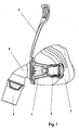
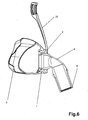
- Fig. 1 shows a nasal mask trained breathing mask.
- the breathing mask according to the invention has a modular structure.
- the basis of the breathing mask is the mask body (1). This is made relatively solid, for example, as an injection molded plastic part.
- On the mask body (1) put the forehead support (2), which ensures a secure fit of the mask on the face of a patient, not shown, and the mask ridge (3), which ensures a tight closure of the breathing mask on the patient by its fit and its elastic nature.
- the connector (4) provides the connection to a hose, not shown, via which the respiratory gas is transported by a respirator to the breathing mask.
- the hose is connected to the connecting piece (4) by means of a sleeve (5) rotatably mounted on the connecting piece (4).
- Fig. 2 shows the already in Fig. 1 illustrated embodiment of a breathing mask according to the invention from the front.
- a clip (6) for tape recording On both sides of the mask body (1) is here a clip (6) for tape recording, but also an asymmetrical embodiment is conceivable. This can be implemented, for example, by the connection of breathing mask and tether with a clip (6) is realized on one side, while on the other side a loop and a hook are used.
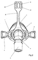
- Fig. 3 shows the breathing mask Fig. 1 from behind.
- a triangular basic shape of the mask bead (3) and the interior of the breathing mask through the patient-side opening of the mask bead (3) can be seen.
- On the upper side of the mask bead (3) protrudes the forehead support (2).
- On the sides of the breathing mask the clips (6) connected to the mask body (1) can be seen for band coupling.
- On the lower side of the mask bead (3) protrudes the connector (4) with the mounted sleeve (5).
- the clips project beyond the mask body towards the patient. This extends the clips the mask body (1) towards the patient. As a result, the attack points for the harness are moved closer to the patient's ears.
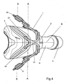
- Fig. 4 shows the breathing mask Fig. 1 from above.
- one of the human anatomy adapted shaping of the forehead support (2) can be seen.
- the head end of the forehead support (2) protrudes in the direction of a patient in order to achieve a sufficient support function on the forehead of a patient without overly tilting the entire breathing mask.
- Shown is the position of the eyelet (36) which serves to couple the harness to the clip.
- You can also see the band coupling in the area of the forehead support (23). Due to the symmetrical structure relative to the plane of symmetry S, the eyelets (36) and the band coupling (23) are present on both sides.
- a plane A passes through both band couplings (23) (and substantially parallel to the forehead of a patient).
- a plane B passes through both eyelets (36) (and substantially parallel to the forehead of a patient).
- the plane A is further from the patient (forehead of a patient) than plane B.
- the attachment points of the banding lie in the planes A and B, respectively.
- the attachment points of the bandage are therefore in a different plane than the attachment points of the band coupling (23 ) of the forehead support.
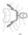
- Fig. 5 is the in Fig. 1 shown breathing mask shown from below.
- Fig. 6 shows a vertical section through the middle of in Fig. 1 shown breathing mask. You can see the mask body (1), the forehead support (2), the masking bead (3) on the side facing a patient and the connecting piece (4) with mounted sleeve (5) on the side facing away from the patient of the breathing mask.
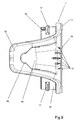
- Fig. 7 a perspective view of the mask body (1) is shown.
- the inner surface of the mask body (1) opens funnel-shaped forward, while its basic shape is defined in the rear, a patient-facing area by a tube of constant diameter.
- In the inner contour of the mask body (1) there are at least two channels (8) which are realized as a recess in the tubular area and which extend into the funnel-shaped area.
- These channels (8) function in duplicate both as receptacles for the mechanical coupling of the forehead support (2), which can be realized, for example, as a bayonet closure, as well as outflow channels for exhaled respiratory gases, the complete contour of the mask body (1) and forehead support ( 2) is defined.
- a tooth (9) is provided in the rear area next to each channel (8), which protrudes radially inwardly from the inner contour of the mask body (1) and which provides the required mechanical resistance for the closure.
- a plurality of spacer ribs (10) are arranged on the inner surface of the mask body (1), which allow a connection of the mask body (1) and forehead support (2) without play or under bias.
- the material in the ring and hopper area is reinforced in accordance with the height of the spacer ribs (10).
- the spacer ribs (10) and the reinforced areas (11) also delimit laterally the outflow surfaces (7).
- the mask body (1) On its sides, the mask body (1) on two wings (12), each having a mechanical structure for receiving a band coupling.
- the band coupling can be done for example by a clip (6).
- this At the front of the mask body (1) this is at the height of the wings (12) provided with nubs (13), which allow a better grip when handling the breathing mask.
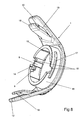
- Fig. 8 shows a perspective view of the mask body (1) from the rear.
- an embodiment of the mask body (1) applied structure for the bayonet lock can be seen.
- the channel (8) and is added in its basic form behind the tooth (9) to an L-shaped recess, which allows the typical plug and screw connection.
- a locking tooth (14) is provided, which secures the connection.
- a mechanical coding (15) in the mask body (1) realized such that the mask bead (3) can connect only in intended positions with the mask body (1). This connection is made by attaching the mask bead (3) to the outer contour (16) of the mask body (1).
- connection is secured by at least one undercut (17) on the outer contour (16) of the mask body (1).
- an oval shape of the outer contour (16) is intended.
- the stiffness and the ratio of height and width of the mask bead (3) can be adjusted.
- a combination of oval design of the outer contour (16) and a circular design of the connection opening of the mask bead (3) is intended.
- the mechanical receiving structure for the band coupling provided by the wings (12) consists essentially of a spring plate (18) in combination with a recess (19) in the structure of the wing (12).
- the recess (19) is funnel-shaped.
- the recess (19) may have a first section with a moderate funnel shape (19a) and a second section with a clear funnel shape (19b).
- the recess (19) opens into a latching area (39) which is at least partially adapted to the shape of the clip (6, 37, 38).
- the mask body additionally has guide structures (13), which point the patient to the recess (19) or the joining direction of the clips.
- the guide structures (13) can also be designed as mechanical structures (channels, channels, edges or the like), which guide the clip in the direction of the recess.
- Fig. 9 shows a side view of the mask body (1). It can be seen a funnel-shaped implementation of the recess (19) in the wing (12), which allows a user-friendly insertion of the band coupling, for example in the form of a St considerablyungsclips (6). This is necessary because this area is not in the field of vision when using or applying the breathing mask of the patient.
- the funnel (19) automatically guides the clip (6) to the locking point, in which the clip (6) is fixed by the spring plate (18).
- Fig. 10 shows an inventive embodiment of the mask body (1) from below.
- a latching pin (20) on the wing (12) facing side of the spring plate (18) which allows the engagement of the Bügelungsclips (6).
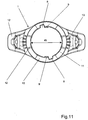
- Fig. 11 shows the in Fig. 7 shown mask body (1) in frontal view.
- the rotational symmetry can be seen around a 180 ° axis located at the center of the inner radius and projecting perpendicularly from the plane of the drawing.
- Fig. 12 shows the in Fig. 7 shown mask body (1) from the rear. Visible are the radially out of the inner contour (7) outstanding spacer ribs (10) and the amplified areas (11) to the outflow channels (8). Also, the shape of the ratchet tooth (14) for the bayonet lock can be seen, which secures the bayonet connection by locking with the counterpart on the forehead support (2) against unwanted twisting and loosening.
- Fig. 13 shows a vertical section through the middle of the in Fig. 7 shown mask body (1). You can see the funnel-shaped opening of the inner contour of the mask body (1) to the right.
- two spacer ribs (10) are arranged at equal distances from each other and the reinforced areas (11). The number and positioning of the spacer ribs (10) may vary in embodiments of the breathing mask according to the invention.
- Fig. 14 shows a horizontal section through the middle of the in Fig. 7 illustrated mask body (1). You can see the positioning of spring plate (18) with locking pin (20) to the main body of the wing (12). The distance from the spring plate (18) and base body of the wing (12) is adapted to a clip (6).
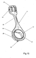
- Fig. 15 shows an inventive embodiment of a forehead support (2).
- the base of the forehead support (2) forms the Stirn contemplatnverbinder (21), with which the forehead support (2) on the mask body (1) is attached.
- a web (22) connects the Stirn contemplatnverbinder (21) with the band coupling (23) on the head of the forehead support (2).
- the band coupling (23) consists of three horizontally juxtaposed, elongated in the vertical direction recesses in the structure of the forehead support (2).
- the two outer recesses each have an additional gap (24) in the outwardly facing structure of the forehead rest (2).
- These gaps (24) can be used for threading the straps at the forehead height of a patient into the band coupling (23).
- the band can also be passed through the centrally positioned recess.
- band coupling (23) it is also intended to other embodiments of the band coupling (23).
- this can also be implemented only by two recesses with additional gap (24).
- the web (22) is significantly reduced in width in the embodiment shown compared to the head part with band coupling (23) and the forehead support connector (21). This allows a responsive, sleek design and material savings.
- the forehead support connector (21) offers to complete the in the mask body (1) applied bayonet lock in positioning and number of existing in the mask body channels (8) corresponding number of locking teeth (25). These are on the outer contour of the connecting ring (26) radially outward and in turn each have a further radially outwardly directed tooth, which together with the locking tooth (14) in the mask body (1) for the locking of the mask body (1) and forehead support (2) in the intended position.
- the inner contour of the Stirn spanverbinders (21) is designed as a ball cage (27), which can mount the connecting piece (4) movable. Toward the connection piece (4), the ball cage (27) is delimited by a ring structure (28) narrowing outwards.
- Fig. 16 shows a perspective view of a forehead support (2) from the rear.
- the illustrated forehead support (2) has two locking teeth (25). However, more locking teeth (25) are also suitable for the respective mask body (1). Recognizable are recesses (29) in the outer contour of the connecting ring (26) adjacent to the locking teeth (25). These recesses (29) serve as additional outflow channels and guide the exhaled gases around the respective closure tooth (25) to the corresponding channel (8) arranged in the mask body (1).
- the use of such a recess (29) as a mechanical coding for a defined orientation of the mask body (1), forehead support (2) and mask bead (3) is conceivable. For this, the structure of the mask body (1) in the region of its mechanical coding (15) must be correspondingly permeable.
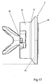
- Fig. 17 is the forehead support (2) off Fig. 15 shown from below.
- the inner contour of the mask body (1) adapted outer contour of Stirn scopenverbinders (21), which also consists of a ring and a Funnel composed. This contour forms the frontal column-side outflow surface (30) and, together with the inner surface of the mask body (1), defines the shape of the outflow channels and the exhalation gap.
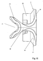
- Fig. 18 shows the forehead rest (2) Fig. 15 from above. It can be seen that the head part of the forehead support (2) protrudes toward a patient in relation to the forehead support connector (21).
- the shape of the band (23) accommodating head of the forehead support (2) has a recess (31) which provides between the forehead of a patient and the band coupling (23) in the forehead support (2) a space in which lie the bands can.
- the shape of the band (23) accommodating head of the forehead support (2) has a recess (31) which provides a space between the forehead of a patient and the band coupling (23) in the forehead rest (2).
- the contour in the region of the recess (31) is rounded with one or more radii.
- the Y-structure can offer an elasticity which allows an adaptation of the head part of the forehead support (13) relative to the forehead of the patient.
- the band coupling (23) has a plane of symmetry S and at least four receiving means (41,42) for a banding end of a harness wherein the receiving means are arranged in pairs on both sides of the plane of symmetry S and a banding end alternatively on the first receiving means (41) or on the second Receiving means (42) can be fastened on one side of the coupling element.
- the receiving means 41 is spatially adjacent to the receiving means 42 and closer to the plane of symmetry S, as the receiving means 42nd
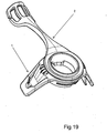
- Mask body (1) and forehead support (2) can be seen as a mounted module in perspective view. In a rotationally symmetrical design of the mask body (1) this can be connected in exactly two positions shifted by 180 ° with the forehead support (2), which are functionally identical. This makes it possible to simplify the assembly of the modules of the breathing mask.
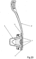
- Fig. 20 shows a side view of the mounted module of mask body (1) and forehead support (2).
- the gaps remaining between the outflow surfaces (7) of the mask body (1) and the outflow channels (8) and the outflow surface (30) of the forehead support connector (21) serve as a guide structure for the exhaled air. Due to the increased structure in the area (11) of the channels (8) in the mask body (1), sealing of the exhalation gap in a defined area is achieved on the upper side in the direction of the forehead support (2). This serves to avoid the outflow of air in areas which are unpleasant for a patient, in particular the eyes.
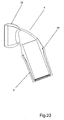
- Fig. 21 shows a perspective view of a connecting piece (4) according to the invention.
- the connecting piece (4) is designed as an angled pipe structure and has at one end a surface contour (32) which corresponds to a partial sphere.
- This part ball (32) serves for the movable connection of connection piece (4) and forehead support (2) by means of the ball cage (27) realized in the forehead support connector (21).
- a rotatably mounted sleeve (5) is mounted as a connection for a hose, not shown.
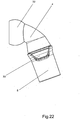
- Fig. 22 shows a side view of a connecting piece (4) according to the invention with an alternative rotatably mounted sleeve (5).
- the sleeve (5) thickened at the respiratory mask oriented end and has at this end recesses (33).
- Fig. 23 shows a vertical section through the connector (4).
- the surface contour in the form of a partial sphere (32) can be seen, the tubular inner structure and a thickening of the structure towards an annular peripheral groove (34), which rotatably supports the sleeve by means of an undercut present on this.
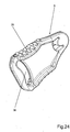
- Fig. 24 shows a perspective view of a banding clip (6).
- the clip (6) recesses, which are occupied with knobs or ribs (35). These serve an improved grip.
- the clip (6) has an eyelet (36) through which a tether can be pulled and secured.
- the clip has a round, mushroom-shaped undercut with a pin. The pin snaps into the locking point (39).
- the spring plate is supported on one side on the mask bead (3).
- the spring plate When inserting the clip (6) in the locking point, the spring plate is urged against the mask bead (3) and deform this elastic.
- the bead which is sprung back into its original form, secures the position of the spring plate, which is also sprung back to its original position.
- the spring plate holds the clip in the locked position in the resting point.
- the bead secures the position of the spring plate.
- the mobility of the clip relative to the mask body is possible through the round, mushroom-shaped undercut on the clip and the fixation in the funnel only in one space level.
- the clip is essentially movable only in one plane parallel to the wing or parallel to the bead.
- a mobility from the clip to the patient's face is only possible in a range of 1 ° to 10 °, preferably 1-7 °.
- Fig. 25 shows a perspective view of the StConsequentlyungsclips (6) from the mounted in the mounted state to the breathing mask side. Visible are a pin (37) with mushroom-shaped undercut (40).
- the undercut (40) can be formed circumferentially round.
- the undercut (40) may also be formed only in partial areas and, for example, be aligned with the opening (36).
- a locking pin (20) to be carried out with a running as a pan recess (38) on the spring plate (18) of the mask body (1) for the engagement of the Bügelungsclips (6) provides.
- the recess (38) / the latching pin (20) may be axially centered in the axial direction of the pin (37).
- the clip is then pivotable vertically up and down about the axis of the pin (37).
- the recess (38) / the latching pin (20) can also be performed axially non-centered in the axial direction of the pin (37) be.
- a pivoting movement of the clip about the axis of the pin (37) then leads to a solution of the connection between the recess (38) and locking pin (20).
- the clip is then pivotable vertically up and down, but this movement is in this case the solution of the clip from the detent position.
Abstract
Description
- Die Erfindung betrifft eine Atemmaske mit einem Maskenkörper und einem gelenkigen Anschlussstück, welches mit einem Atemschlauch verbindbar ist.
- Atemmasken werden beispielsweise im Zusammenhang mit Beatmungsgeräten verwendet, um Atemgas zum Patienten zu leiten und eine Ableitung des ausgeatmeten Atemgases zu unterstützen. Die Atemmaske ist typischerweise über einen Atemschlauch mit einem Beatmungsgerät verbunden.
- Ein Nachteil bekannter Atemmasken war, die beim Ausatmen durch den Maskenkörper und den Beatmungsschlauch entstehende, für den Patienten und die Umgebung unangenehme, akustische Beeinträchtigung. Zudem verursachte der ausgeatmete Luftstrom einen am Patienten entlang streichenden kühlen Luftzug. Diese Herausforderungen wurden durch eine Adaption der Maske gemäß
DE 10 2005 041 717 A1 undEP 1 632 262 B1 mittels geeigneter Anordnung und Struktur von Ausatemspalten zwischen Maskenkörper und Sicherungsring gemeistert. - Fertigungs- und wartungstechnischer Nachteil ist, dass die Luft in den bekannten Atemmasken durch Durchbrüche im Maskenkörper hindurch zu den Ausatemspalten geleitet wird. Zudem schwächen Durchbrüche die mechanische Stabilität des Maskenkörpers.
- Des Weiteren bestehen die Masken aus vielen Einzelteilen, die zwar eine erhöhte Anpassbarkeit an den Patienten erlauben, jedoch komplex zu montieren und teuer in der Fertigung sind.
- Bekannte Masken stellen den Raum zur Aufnahme der Atemöffnungen des Patienten überwiegend innerhalb des Maskenkörpers zur Verfügung. Dies sorgt für einen erhöhten Materialbedarf im Bereich des Maskenkörpers, da dieser ein größeres Volumen umschließen muss.
- Weiterhin stellt bei bekannten Atemmasken die Ankopplung der Bänderung zwecks sicherer Fixierung der Maske am Kopf des Patienten während des Aufsetzens der Maske häufig hohe Anforderungen an die Fingerfertigkeit des Patienten, da die Sicht auf die entsprechenden Verbindungsteile nicht gegeben ist.
Eine Aufgabe der Erfindung ist es eine einfache Ankopplung der Bänderung bereitzustellen. - Die Aufgabe wird gelöst durch eine Atemmaske mit einem Maskenwulst, der die Maske zum Patienten hin abdichtet, einem Maskenkörper und zumindest einem Flügel der der Aufnahme eines Bänderungsclips dient, wobei der Bänderungsclip eine Kopfbänderung an der Maske fixiert, dadurch gekennzeichnet, dass der Flügel eine trichterförmige Aussparung aufweist und der Clip im Bereich eines Rastpunktes der Aussparung verrastet.
- Die Erfindung ist dadurch gekennzeichnet, dass die Aussparung zwei unterschiedlich stark trichterförmig geformte Bereiche aufweist.
- Die Erfindung ist dadurch gekennzeichnet, dass der Rastpunkt im engsten Bereich der trichterförmigen Aussparung angeordnet ist.
Die Erfindung ist auch dadurch gekennzeichnet, dass der Flügel federnd ausgebildet ist. - Die Erfindung ist dadurch gekennzeichnet, dass der Maskenkörper im Bereich des Flügels eine Federplatte aufweist, die benachbart zu der und/oder innerhalb der Aussparung angeordnet ist.
- Die Erfindung ist dadurch gekennzeichnet, dass die Federplatte sich an dem Maskenwulst zumindest teilweise anlehnt.
- Die Erfindung ist dadurch gekennzeichnet, dass der Maskenkörper Leitstrukturen aufweist, die den Patienten auf die Aussparung und die Fügerichtung der Clips hinweisen.
- Die Erfindung ist dadurch gekennzeichnet, dass die Leitstrukturen an der Basis der Federplatte angeordnet sind.
- Die Erfindung ist dadurch gekennzeichnet, dass der Trichter den Clip automatisch zum Rastpunkt führt, in dem der Clip durch die Federplatte fixiert wird.
- Die Erfindung ist auch dadurch gekennzeichnet, dass der Clip eine Vertiefung aufweist, die im Zusammenspiel mit dem Rastzapfen für das Einrasten des Clips in der vorgesehenen Position am Flügel in dem Rastpunkt sorgt.
- Die Erfindung ist dadurch gekennzeichnet, dass der Clip über die Federplatte gleitet, wenn er zum Rastpunkt führt wird.
- Atemmaske nach zumindest einem der vorhergehenden Ansprüche gekennzeichnet durch einen Rastzapfen (20) auf der dem Flügel (12) zugewandten Seite der Federplatte (18), der das Einrasten des Bänderungsclips (6) ermöglicht.
- Atemmaske nach zumindest einem der vorhergehenden Ansprüche, die eine Stirnstütze (2) aufweist.
- Atemmaske nach zumindest einem der vorhergehenden Ansprüche, die zwei unterschiedliche mechanische Hilfsstrukturen für eine Ankopplung von Bändern aufweist.
- Atemmaske nach zumindest einem der vorhergehenden Ansprüche, deren Stirnstütze (2) durch ihren Aufbau mindestens zwei Optionen zur Ankopplung von Bändern aufweist.
- Atemmaske nach zumindest einem der vorhergehenden Ansprüche, deren Bandankopplung durch mindestens einen Clip (6) realisiert ist.
- Atemmaske nach zumindest einem der vorhergehenden Ansprüche, deren mechanische Hilfsstruktur zur Bandankopplung durch eine trichterförmige Struktur (19) im Maskenkörper (1) gegeben ist.
- Atemmaske nach zumindest einem der vorhergehenden Ansprüche dadurch gekennzeichnet, dass der Clip (6) an seiner Ober- und Unterseite Vertiefungen oder Erhebungen aufweist, die mit Noppen oder Rippen (35) besetzt sind und an einem Ende eine Öse (36) aufweist, durch die ein Halteband gezogen und so befestigt werden kann.
- Die Erfindung ist dadurch gekennzeichnet, dass der Clip (6) einen Zapfen (37) mit pilzförmigem Hinterschnitt aufweist.
- Die Erfindung ist dadurch gekennzeichnet, dass der Clip (6) einen Zapfen (37) mit pilzförmigem Hinterschnitt aufweist sowie eine als Pfanne ausgeführte Vertiefung (38) im Kopf des Zapfens (37) aufweist.
- Die Erfindung ist dadurch gekennzeichnet, dass die Vertiefung im Zusammenspiel mit dem Rastzapfen auf der Federplatte des Maskenkörpers für das Einrasten des Bänderungsclips in der vorgesehenen Position am Flügel des Maskenkörpers sorgt.
- Die Erfindung ist dadurch gekennzeichnet, dass die Vertiefung (38) /der Rastzapfen (20) in axialer Richtung des Zapfens (37) axial zentriert ausgeführt sind.
- Die Erfindung ist dadurch gekennzeichnet, dass die Vertiefung (38) /der Rastzapfen (20) in axialer Richtung des Zapfens (37) axial unzentriert ausgeführt sind, eine Schwenkbewegung des Clips um die Achse des Zapfens (37) führt dann zu einer Lösung der Verbindung zwischen Vertiefung (38) und Rastzapfen (20).
- Eine Aufgabe der Erfindung ist es, die Leitstrukturen für die ausgeatmeten Atemgase zu den Ausatemspalten so anzupassen, dass keine Durchbrüche im Maskenkörper erforderlich sind.
- Diese Aufgabe wird erfindungsgemäß dadurch gelöst, dass die Leitstrukturen im durch Aussparungen entstehenden Raum zwischen Maskenkörper und einem Stirnstützenverbinder gebildet werden.
- Eine weitere Aufgabe der Erfindung ist es, die Anzahl der benötigten Einzelteile zu reduzieren, um eine kostengünstige Fertigung und eine einfache Montage der Atemmaske zu ermöglichen.
- Diese Aufgabe wird erfindungsgemäß dadurch gelöst, dass die erfindungsgemäße Stirnstütze mehrere Funktionen vereint. So sind in einem einzigen Teil die Funktionen der Stirnstütze, des Sicherungsringes und des Kugelgelenks zur Aufnahme eines Anschlussstücks kombiniert. Zusätzlich definiert der Stirnstützenverbinder durch seine Kontur gemeinsam mit dem Maskenkörper eine Leitstruktur für die ausgeatmeten Atemgase eines Patienten.
- Die Montage der Atemmaske kann zusätzlich dadurch vereinfacht werden, dass der Maskenkörper rotationssymmetrisch ausgeführt wird, wodurch dieser in zwei zueinander um 180° gedrehten Positionen funktionsgleich verbaut werden kann.
- Eine weitere Aufgabe der Erfindung ist es Material und Fertigungsaufwand am Maskenkörper einzusparen.
- Diese Aufgabe wird dadurch erfüllt, dass der an den Atemöffnungen des Patienten benötigte Raum innerhalb des Maskenwulstes zur Verfügung gestellt wird.
Weiter ist es eine Aufgabe der Erfindung die Bandankopplung an die Atemmaske zur erleichtern. - Diese Aufgabe wird erfindungsgemäß durch eine Anpassung des mechanischen Aufbaus der Bandankopplung in der Form erfüllt, dass eine Führungsstruktur im Maskenkörper integriert wird, die die auf der Bandseite vorhandene Kopplungsstruktur im Ankopplungsvorgang helfend zum Fixierpunkt führt. Dadurch wird die Ankopplung ohne Sicht wesentlich vereinfacht.
- Des Weiteren wird diese Aufgabe auch dadurch erfüllt, dass die Stirnstütze verschiedene Optionen für die Bandankopplung bietet.
- Die erfindungsgemäße Atemmaske, die nicht nur als Einzelteil, sondern auch als Element eines ganzen Beatmungsgerätes zu verstehen ist, ist bevorzugt modular aufgebaut. Diese Modularität umfasst vier wesentliche Bestandteile, die durch einen Maskenkörper, eine Stirnstütze, einen Maskenwulst und ein gelenkiges Anschlussstück gegeben sind. Das Anschlussstück ist mit einem Atemschlauch verbindbar, der das Atemgas zwischen Atemmaske und Beatmungsgerät transportiert. Weiterhin zeichnet sich die erfindungsgemäße Atemmaske durch die Integration von mindestens einem Ausatemspalt aus, der von bestimmten Bereichen der Oberflächen von Maskenkörper und Stirnstütze zwischen diesen begrenzt wird. Zur Fixierung der Atemmaske am Kopf eines Patienten sind Bänder vorgesehen, für die die erfindungsgemäße Atemmaske Ankopplungsstrukturen zur Verfügung stellt.
- Der Maskenkörper dient als Basis der Atemmaske und stellt Verbindungsstrukturen zur Stirnstütze, zum Maskenwulst und zu der Bänderung zur Verfügung. Die Verbindungsstrukturen zu Maskenwulst und Stirnstütze sind bevorzugt mechanisch kodiert, um eine definierte Positionierung der Elemente zueinander sicherzustellen. Als Verbindungsform von Maskenkörper und Stirnstütze ist insbesondere an einen Bajonettverschluss mit Einrastfunktion gedacht. Die Verbindung von Maskenkörper und Maskenwulst kann beispielsweise durch eine Steckverbindung mit Hinterschnitt oder Zweikomponentenverklebung realisiert werden.
- Eine vorteilhafte Ausführungsform des Maskenkörpers ist es, diesen rotationssymmetrisch auszulegen. So kann der Maskenkörper funktional identisch in zwei zueinander um 180° gedrehten Positionen in der Atemmaske verbaut werden. Jedoch sind auch, zum Beispiel zwecks mechanischer Kodierung oder der Gestaltung von Ausatemspalten, nicht vollständig rotationssymmetrische Maskenkörper für eine erfindungsgemäße Atemmaske denkbar.
- An seinen Seiten weist der Maskenkörper Ankopplungsstrukturen für Bänder auf. Insbesondere ist dabei an die Kombination einer Führungsstruktur, die das Gegenstück zur Ankopplung auf Bandseite zum Fixierpunkt führt, mit einer Fixiermechanik gedacht. Die Fixiermechanik kann erfindungsgemäß beispielsweise als Federplatte mit einem Zapfen ausgeführt sein, während eine trichterförmige Führungsstruktur das bänderseitige Koppelstück in den durch Federplatte und Zapfen definierten Rastpunkt führt.
- Die Grundform der inneren Oberfläche des Maskenkörpers ist zum Beispiel ringförmig ausgelegt und öffnet sich auf der einem Patienten abgewandten Seite trichterförmig. Weiterhin weist die Oberfläche im inneren Radius des Maskenkörpers Strukturen auf, die der mechanischen Sicherung der Verbindung mit der Stirnstütze und der Begrenzung von einer oder mehreren Atemgas-Leitstrukturen sowie mindestens einem Ausatemspalt dienen. Diese Strukturen können beispielsweise durch Distanzrippen gegeben sein, die eine Verbindung von Maskenkörper und Stirnstütze ohne Spiel erlauben und die Ausatemspalte begrenzen. Weiterhin sind Strukturen vorgesehen, die eine sichere Verbindung und Fixierung von Maskenkörper und Stirnstütze ermöglichen. Insbesondere ist dabei an kanalartige Aussparungen in zur radialen Ebene orthogonaler Richtung gedacht, die als Führung für Bajonettzähne am Verbindungsstück der Stirnstütze dienen. Des Weiteren dienen die nach dem Verschrauben von Maskenkörper und Stirnstütze freiwerdenden Kanäle in einer vorteilhaften Ausführungsform der erfindungsgemäßen Atemmaske als Leitung für die ausgeatmeten Atemgase eines Patienten vom Inneren der Atemmaske zum Trichter.
- Die trichterförmige Öffnung erlaubt es die ausgeatmeten Atemgase eines Patienten in einem vorteilhaften Winkel durch mindestens einen Ausatemspalt an der vom Patienten abgewandten Seite aus der Atemmaske abzuleiten.
- Vorteilhaft ist eine Formgebung innerhalb der trichterförmigen Öffnung des Maskenkörpers, die Ausatemspalte in Verbindung mit der montierten Stirnstütze in definierten Bereichen automatisch verschließt. Zum Beispiel ist dabei an, den Bereich gedacht, in dem Ausatemgase direkt oder abgelenkt durch Teile der Atemmaske in Richtung der Augen austreten können, da dies von Patienten als besonders unangenehm wahrgenommen wird.
- Jedoch ist auch an Ausführungsformen gedacht, die im nach oben gerichteten Bereich des Trichters mindestens einen Ausatemspalt aufweisen. Auch können Ausführungsformen der erfindungsgemäßen Atemmaske zusätzlich die weitere Struktur der Stirnstütze insbesondere im Bereich des Stegs als führende Oberfläche für das entweichende Atemgas nutzen.
- Der Maskenwulst dient der Aufnahme der Atemöffnungen und des Abdichtens der Maske am Gesicht eines Patienten. Der Maskenwulst kann aus einem relativ weichen Material gefertigt sein, das zum Zwecke der Abdichtung am Gesicht eines Patienten und zur Montage an dem Maskenkörper eine bestimmte Elastizität aufweisen kann. Besonders ist an Kunststoff als Material des Maskenwulstes gedacht. Die Grundform des, Maskenwulstes ist bevorzugter Weise an die menschliche Anatomie angepasst und für Nasalmasken entsprechend triangulär vorgesehen. An der vom Patienten abgewandten Seite befindet sich eine Verbindungsöffnung, die in Größe und Form an die Verbindungsform des Maskenkörpers angepasst ist. Durch die Kombination von verschiedenen Formen bei weiterhin angepassten Umfängen auf Seiten von Maskenwulst und Maskenkörper, lassen sich im relativ weichen Material des Maskenwulstes die Steifigkeit und das Verhältnis von Breite und Höhe einstellen. Denkbar sind zum Beispiel eine ovale Ausführung der Wulstaufnahme am Maskenkörper und eine kreisrunde Ausführung der Öffnung am Maskenwulst.
- Die Stirnstütze der erfindungsgemäßen Atemmaske ist einteilig ausgeführt und vereint weitere Funktionen. Diese Funktionen sind die Vervollständigung der Leitstruktur für die ausgeatmeten Atemgase eines Patienten in Kombination mit den im Maskenkörper angelegten Merkmalen, insbesondere der trichterförmigen Zuleitung der Atemgase zu dem mindestens einen Ausatemspalt, die gelenkige Anbindung des Anschlussstückes, beispielsweise durch einen integrierten Kugelkäfig, sowie eine Bandankopplung.
- Die Erfindung wird im Folgenden anhand der Figuren in beispielhafter Ausführungsform erläutert. Es zeigen:
-
Fig. 1 : eine als Nasalmaske ausgeführte Atemmaske in seitlicher Ansicht, -
Fig. 2 : die inFig. 1 gezeigte Atemmaske von vorn, -
Fig. 3 : die inFig. 1 gezeigte Atemmaske von hinten, -
Fig. 4 : die inFig. 1 gezeigte Atemmaske von oben, -
Fig. 5 : die inFig. 1 gezeigte Atemmaske von unten, -
Fig. 6 : einen vertikalen Schnitt der inFig. 1 gezeigten Atemmaske, -
Fig. 7 : eine perspektivische Darstellung einer erfindungsgemäßen Ausführungsform eines Maskenkörpers von vorn, -
Fig. 8 : eine perspektivische Darstellung des inFig. 7 gezeigten Maskenkörpers von hinten, -
Fig. 9 : eine seitliche Ansicht des Maskenkörpers ausFig. 7 , -
Fig. 10 : eine Ansicht des Maskenkörpers ausFig. 7 von oben, -
Fig. 11 : eine Ansicht des Maskenkörpers ausFig. 7 von vorn, -
Fig. 12 : eine Ansicht des Maskenkörpers ausFig. 7 von hinten, -
Fig. 13 : einen vertikalen Schnitt durch den Maskenkörper ausFig. 7 , -
Fig. 14 : einen horizontalen Schnitt durch den Maskenkörper ausFig. 7 , -
Fig. 15 : eine perspektivische Ansicht einer erfindungsgemäßen Ausführungsform der Stirnstütze von vorn, -
Fig. 16 : eine perspektivische Ansicht einer Stirnstütze ausFig. 15 von hinten, -
Fig. 17 : eine Ansicht der Stirnstütze ausFig. 15 von unten, -
Fig. 18 : eine Ansicht der Stirnstütze ausFig. 15 von oben, -
Fig. 19 : eine perspektivische Ansicht eines Moduls einer erfindungsgemäßen Beatmungsvorrichtung bestehend aus Maskenkörper und Stirnstütze, -
Fig. 20 : eine Seitenansicht des inFig. 19 gezeigten Moduls, -
Fig. 21 : eine perspektivische Ansicht eines erfindungsgemäßen Anschlussstücks, -
Fig. 22 : eine seitliche Ansicht eines erfindungsgemäßen Anschlussstücks, -
Fig. 23 : einen vertikalen Schnitt des Anschlussstücks ausFig. 21 , -
Fig. 24 : eine perspektivische Darstellung eines erfindungsgemäßen Clips für die Bandaufnahme und die Verbindung mit dem Maskenkörper von der der Maske abgewandten Seite, -
Fig. 25 : eine perspektivische Darstellung des Clips ausFig. 24 von der der Maske zugewandten Seite. -
Fig. 1 zeigt eine als Nasalmaske ausgebildete Atemmaske. Die erfindungsgemäße Atemmaske ist modular aufgebaut. Als Basis der Atemmaske dient der Maskenkörper (1). Dieser ist beispielsweise als Spritzgussteil aus Kunststoff relativ fest ausgeführt. An dem Maskenkörper (1) setzen die Stirnstütze (2), die einen sicheren Sitz der Maske auf dem Gesicht eines nicht dargestellten Patienten gewährleistet, und der Maskenwulst (3), der durch seine Passform und seine elastische Beschaffenheit für einen dichten Abschluss der Atemmaske am Patienten sorgt, an. Das Anschlussstück (4) stellt die Verbindung zu einem nicht dargestellten Schlauch dar, über den das Atemgas von einem Beatmungsapparat zur Atemmaske transportiert wird. Der Schlauch wird mittels einer auf dem Anschlussstück (4) drehbeweglich gelagerten Hülse (5) mit dem Anschlussstück (4) verbunden. Mithilfe von seitlich mit dem Maskenkörper (1) verbindbaren Clips (6) kann die Atemmaske durch Bänder sicher am Kopf des Patienten fixiert werden. -
Fig. 2 zeigt die bereits inFig. 1 dargestellte Ausführungsform einer erfindungsgemäßen Atemmaske von vorn. Zu erkennen ist die Symmetrie des Aufbaus entlang der vertikalen Mittelachse. An beiden Seiten des Maskenkörpers (1) befindet sich hier ein Clip (6) zur Bandaufnahme, jedoch ist auch eine asymmetrische Ausführungsform denkbar. Dies kann beispielsweise umgesetzt werden, indem auf einer Seite die Verbindung von Atemmaske und Halteband mit einem Clip (6) realisiert wird, während auf der anderen Seite eine Schlaufe und ein Haken genutzt werden. -
Fig. 3 zeigt die Atemmaske ausFig. 1 von hinten. Zu sehen ist eine trianguläre Grundform des Maskenwulstes (3) sowie das Innere der Atemmaske durch die patientenseitige Öffnung des Maskenwulstes (3) hindurch. An der oberen Seite des Maskenwulstes (3) ragt die Stirnstütze (2) hervor. An den Seiten der Atemmaske sind die mit dem Maskenkörper (1) verbundenen Clips (6) zur Bandankopplung zu sehen. An der unteren Seite des Maskenwulstes (3) ragt das Anschlussstück (4) mit der montierten Hülse (5) hervor. Die Clips überragen den Maskenkörper in Richtung auf den Patienten. Damit verlängern die Clips den Maskenkörper (1) in Richtung auf den Patienten. Daraus ergibt sich, dass die Angriffpunkte für die Bänderung näher zu den Ohren des Patienten verschoben werden. -
Fig. 4 zeigt die Atemmaske ausFig. 1 von oben. In dieser Ansicht ist eine der menschlichen Anatomie angepasste Formgebung der Stirnstütze (2) erkennbar. Aus der sich aus der Verbindung mit dem Maskenkörper (1) ergebenden Fläche ragt das Kopfende der Stirnstütze (2) in Richtung eines Patienten, um auch ohne übermäßiges Neigen der gesamten Atemmaske eine ausreichende Stützfunktion an der Stirn eines Patienten zu erreichen. Eingezeichnet ist die Lage der Öse (36) die der Ankopplung der Bänderung an den Clip dient. Zu erkennen ist auch die Bandankopplung im Bereich der Stirnstütze (23). Durch den symmetrischen Aufbau relativ zu der Symmetrieebene S sind die Ösen (36) und die Bandankopplung (23) beidseitig vorhanden. Eine Ebene A verläuft durch beide Bandankopplungen (23) (und im Wesentlichen parallel zur Stirn eines Patienten) . Eine Ebene B verläuft durch beide Ösen (36) (und im Wesentlichen parallel zur Stirn eines Patienten). Die Ebene A ist weiter von dem Patienten (Stirn eines Patienten) als Ebene B. Die Anknüpfpunkte der Bänderung liegen in den Ebenen A bzw. B. Die Anknüpfpunkte der Bänderung sind daher bei den Clips in einer anderen Ebene als die Anknüpfpunkte der Bandankopplung (23) der Stirnstütze. - In
Fig. 5 ist die inFig. 1 gezeigte Atemmaske von unten dargestellt. Zu sehen sind der Maskenkörper (1), die Stirnstütze (2), der Maskenwulst (3) auf der einem Patienten zugewandten Seite, das Anschlussstück (4) auf der einem Patienten abgewandten Seite mit montierter Hülse (5) und, Clips (6) zur Bandankopplung an die Atemmaske. -
Fig. 6 zeigt einen vertikalen Schnitt durch die Mitte der inFig. 1 gezeigten Atemmaske. Zu sehen sind der Maskenkörper (1), die Stirnstütze (2), der Maskenwulst (3) auf der einem Patienten zugewandten Seite und das Anschlussstück (4) mit montierter Hülse (5) auf der einem Patienten abgewandten Seite der Atemmaske. - In
Fig. 7 wird eine perspektivische Darstellung des Maskenkörpers (1) gezeigt. Zu erkennen sind mehrere Ausströmflächen (7) auf der innenliegenden Oberfläche des Maskenkörpers (1). Die innenliegende Oberfläche des Maskenkörpers (1) öffnet sich nach vorn trichterförmig, während ihre Grundform im hinteren, einem Patienten zugewandten Bereich durch ein Rohr konstanten Durchmessers definiert wird. In der inneren Kontur des Maskenkörpers (1) befinden sich mindestens zwei Kanäle (8), die als Aussparung im rohrförmigen Bereich realisiert sind und die sich bis in den trichterförmigen Bereich erstrecken. Diese Kanäle (8) fungieren in doppelter Funktion sowohl als Aufnahmen für die mechanische Ankopplung der Stirnstütze (2), die beispielsweise als Bajonettverschluss realisiert werden kann, als auch als Abströmkanäle für ausgeatmete Atemgase, deren vollständige Kontur gemeinsam von Maskenkörper (1) und Stirnstütze (2) definiert wird. Für den Bajonettverschluss ist im hinteren Bereich neben jedem Kanal (8) jeweils ein Zahn (9) vorgesehen, der radial nach innen aus der inneren Kontur des Maskenkörpers (1) herausragt und der den benötigten mechanischen Widerstand für den Verschluss bietet. Des Weiteren sind auf der inneren Oberfläche des Maskenkörpers (1) mehrere Distanzrippen (10) angeordnet, die eine Verbindung von Maskenkörper (1) und Stirnstütze (2) ohne Spiel bzw. unter Vorspannung ermöglichen. Im Bereich (11) der Abströmkanäle (8) ist das Material im Ring- und Trichterbereich entsprechend der Höhe der Distanzrippen (10) verstärkt. Die Distanzrippen (10) und die verstärkten Bereiche (11) begrenzen zudem seitlich die Ausströmflächen (7). - Denkbar sind auch zusätzliche Aussparungen im trichterförmigen Bereich der inneren Oberfläche des Maskenkörpers (1), um einen oder mehrere zusätzliche Ausströmkanäle zu formen.
- An seinen Seiten weist der Maskenkörper (1) zwei Flügel (12) auf, die jeweils eine mechanische Struktur zur Aufnahme einer Bandankopplung aufweisen. Die Bandankopplung kann beispielsweise durch einen Clip (6) erfolgen. Im vorderen Bereich des Maskenkörpers (1) ist dieser auf Höhe der Flügel (12) mit Noppen (13) versehen, die eine bessere Griffigkeit bei der Handhabung der Atemmaske ermöglichen.
-
Fig. 8 zeigt eine perspektivische Darstellung des Maskenkörpers (1) von hinten. In dieser Darstellung ist eine Ausführung der im Maskenkörper (1) angelegten Struktur für den Bajonettverschluss zu erkennen. Der Kanal (8) und wird in seiner Grundform hinter dem Zahn (9) zu einer L-förmigen Aussparung ergänzt, was die typische Steck- und Schraubverbindung ermöglicht. Im Konturbereich hinter dem Zahn (9) ist ein Rastzahn (14) vorgesehen, der die Verbindung sichert. Zusätzlich ist in der inFig. 8 gezeigten Ausführungsform der Atemmaske eine mechanische Kodierung (15) im Maskenkörper (1) derart realisiert, dass der Maskenwulst (3) sich nur in vorgesehenen Positionen mit dem Maskenkörper (1) verbinden lässt. Diese Verbindung erfolgt durch ein Aufstecken des Maskenwulstes (3) auf die äußere Kontur (16) des Maskenkörpers (1). Gesichert wird die Verbindung in der gezeigten Ausführungsform durch mindestens einen Hinterschnitt (17) auf der äußeren Kontur (16) des Maskenkörpers (1). Denkbar sind neben der dargestellten kreisrunden äußeren Kontur (16) auch andersförmige Ausführungen. Insbesondere ist an eine ovale Form der äußeren Kontur (16) gedacht. In Kombination mit der Form der Verbindungsöffnung des Maskenwulstes (3), die mit einem inneren Umfang kleiner oder gleich der äußeren Kontur (16) des Maskenkörpers (1), auch anders geformt sein kann, können die Steifigkeit und das Verhältnis von Höhe und Breite des Maskenwulstes (3) eingestellt werden. Insbesondere ist an eine Kombination von ovaler Ausführung der äußeren Kontur (16) und einer kreisrunden Ausführung der Verbindungsöffnung des Maskenwulstes (3) gedacht. Neben der gezeigten Verbindung von Maskenwulst (3) und Maskenkörper (1) durch einen Hinterschnitt (17), sind auch andere Optionen denkbar. Zum Beispiel ist auch ein Verkleben der Module mit Hilfe eines Zweikomponentenklebstoffs möglich.
Die von im Bereich der Flügel (12) bereitgestellte mechanische Aufnahmestruktur für die Bandankopplung besteht im Wesentlichen aus einer Federplatte (18) in Kombination mit einer Aussparung (19) in der Struktur des Flügels (12). Die Aussparung (19) ist trichterförmig. Dabei kann die Aussparung (19) einen ersten Abschnitt mit mäßiger Trichterform (19a) und einen zweiten Abschnitt mit deutlicher Trichterform (19b) aufweisen. Die Aussparung (19) mündet in einem Rastbereich (39) der der Form des Clips (6, 37,38) zumindest abschnittsweise angepasst ist. Der Maskenkörper weist zusätzlich Leitstrukturen (13) auf, die den Patienten auf die Aussparung (19) bzw. die Fügerichtung der Clips hinweisen. Alternativ können die Leitstrukturen (13) auch als mechanische Strukturen (Rinnen, Kanäle, Kanten oder dergleichen) ausgebildet sein, die den Clip in Richtung der Aussparung leiten. -
Fig. 9 zeigt eine Seitenansicht des Maskenkörpers (1) . Zu sehen ist eine trichterförmige Umsetzung der Aussparung (19) im Flügel (12), die ein benutzerfreundliches Einführen der Bandankopplung, zum Beispiel in Form eines Bänderungsclips (6), ermöglicht. Dies ist erforderlich, da sich dieser Bereich bei Nutzung oder Anlegen der Atemmaske nicht im Sichtfeld des Patienten befindet. Der Trichter (19) führt den Clip (6) automatisch zum Rastpunkt, in dem der Clip (6) durch die Federplatte (18) fixiert wird. -
Fig. 10 zeigt eine erfindungsgemäße Ausführungsform des Maskenkörpers (1) von unten. Zu erkennen ist ein Rastzapfen (20) auf der dem Flügel (12) zugewandten Seite der Federplatte (18), der das Einrasten des Bänderungsclips (6) ermöglicht. -
Fig. 11 zeigt den inFig. 7 dargestellten Maskenkörper (1) in frontaler Ansicht. Zu erkennen ist die Rotationssymmetrie um eine im Mittelpunkt des inneren Radius befindlichen, senkrecht aus der Zeichenebene herausragenden Achse um 180°. -
Fig. 12 zeigt den inFig. 7 dargestellten Maskenkörper (1) von hinten. Ersichtlich sind die radial aus der inneren Kontur (7) herausragenden Distanzrippen (10) und die verstärken Bereiche (11) um die Ausströmkanäle (8). Auch ist die Form der Rastzahns (14) für den Bajonettverschluss zu sehen, der die Bajonettverbindung durch die Verrastung mit dem Gegenstück an der Stirnstütze (2) gegen ungewolltes Verdrehen und Lösen sichert. -
Fig. 13 zeigt einen vertikalen Schnitt durch die Mitte des inFig. 7 gezeigten Maskenkörpers (1). Zu sehen ist die trichterförmige Öffnung der inneren Kontur des Maskenkörpers (1) zur rechten Seite. Im zwischen den verstärkten Bereichen (11) um die Ausströmkanäle (8) liegenden Bereich der inneren Oberfläche des Maskenkörpers (1), sind jeweils zwei Distanzrippen (10) in gleichen Abständen zueinander und zu den verstärkten Bereichen (11) angeordnet. Die Anzahl und Positionierung der Distanzrippen (10) kann in erfindungsgemäßen Ausführungsformen der Atemmaske variieren. -
Fig. 14 zeigt einen horizontalen Schnitt durch die Mitte des inFig. 7 dargestellten Maskenkörpers (1). Zu sehen ist die Positionierung von Federplatte (18) mit Rastzapfen (20) zum Grundkörper des Flügels (12). Der Abstand von Federplatte (18) und Grundkörper des Flügels (12) ist auf einen Clip (6) angepasst. -
Fig. 15 zeigt eine erfindungsgemäße Ausführungsform einer Stirnstütze (2). Die Basis der Stirnstütze (2) bildet der Stirnstützenverbinder (21), mit dem die Stirnstütze (2) am Maskenkörper (1) befestigt wird. Ein Steg (22) verbindet den Stirnstützenverbinder (21) mit der Bandankopplung (23) am Kopf der Stirnstütze (2). Die Bandankopplung (23) besteht aus drei horizontal nebeneinander angeordneten, in vertikaler Richtung länglich ausgedehnten Aussparungen in der Struktur der Stirnstütze (2). Die beiden äußeren Aussparungen weisen jeweils einen zusätzlichen Spalt (24) in der nach außen gewandten Struktur der Stirnstütze (2) auf. Diese Spalte (24) können zum Einfädeln der Haltebänder auf Stirnhöhe eines Patienten in die Bandankopplung (23) genutzt werden. Alternativ kann das Band auch durch die mittig positionierte Aussparung geführt werden. - Es ist auch an andere Ausführungsformen der Bandankopplung (23) gedacht. Beispielsweise kann diese auch nur durch zwei Aussparungen mit zusätzlichem Spalt (24) umgesetzt werden. Der Steg (22) ist in seiner Breite in der gezeigten Ausführungsform gegenüber dem Kopfteil mit Bandankopplung (23) und dem Stirnstützenverbinder (21) signifikant reduziert. Dies ermöglicht ein ansprechendes, schlankes Design und die Einsparung von Material.
- Der Stirnstützenverbinder (21) bietet zur Vervollständigung des im Maskenkörper (1) angelegten Bajonettverschlusses eine in Positionierung und Anzahl der im Maskenkörper vorhandenen Kanäle (8) entsprechende Anzahl an Verschlusszähnen (25). Diese stehen auf der äußeren Kontur des Verbindungsringes (26) radial nach außen und weisen ihrerseits jeweils einen weiteren radial nach außen gerichteten Zahn auf, der gemeinsam mit dem Rastzahn (14) im Maskenkörper (1) für die Arretierung von Maskenkörper (1) und Stirnstütze (2) in der vorgesehenen Position sorgt. Die innere Kontur des Stirnstützenverbinders (21) ist als Kugelkäfig (27) ausgeführt, der das Anschlussstück (4) beweglich lagern kann. Zum Anschlussstück (4) hin wird der Kugelkäfig (27) durch eine sich nach außen verengende Ringstruktur (28) begrenzt.
-
Fig. 16 zeigt eine perspektivische Darstellung einer Stirnstütze (2) von hinten. Die dargestellte Stirnstütze (2) weist zwei Verschlusszähne (25) auf. Jedoch sind auch mehr Verschlusszähne (25) passend zum jeweiligen Maskenkörper (1) denkbar. Erkennbar sind Aussparungen (29) in der äußeren Kontur des Verbindungsringes (26) neben den Verschlusszähnen (25). Diese Aussparungen (29) dienen als zusätzliche Ausströmkanäle und leiten die ausgeatmeten Gase um den jeweiligen Verschlusszahn (25) zum entsprechenden im Maskenkörper (1) angeordneten Kanal (8). Zusätzlich ist auch die Nutzung einer solchen Aussparung (29) als mechanische Kodierung für eine definierte Ausrichtung von Maskenkörper (1), Stirnstütze (2) und Maskenwulst (3) denkbar. Dafür muss die Struktur des Maskenkörpers (1) im Bereich seiner mechanischen Kodierung (15) entsprechend durchlässig sein.
InFig. 17 ist die Stirnstütze (2) ausFig. 15 von unten dargestellt. Zu erkennen ist die der inneren Kontur des Maskenkörpers (1) angepasste äußere Kontur des Stirnstützenverbinders (21), die sich ebenfalls aus einem Ring und einem Trichter zusammensetzt. Diese Kontur bildet die stirnstützenseitige Abströmoberfläche (30) und definiert gemeinsam mit der innenliegenden Oberfläche des Maskenkörpers (1) die Form der Abströmkanäle und der Ausatemspalte. -
Fig. 18 zeigt die Stirnstütze (2) ausFig. 15 von oben. Zu erkennen ist, dass das Kopfteil der Stirnstütze (2) in Relation zum Stirnstützenverbinder (21) zu einem Patienten hin ragt. Die Form des die Bandankopplung (23) beherbergenden Kopfes der Stirnstütze (2) weist eine Aussparung (31) auf, die zwischen der Stirn eines Patienten und der Bandankopplung (23) in der Stirnstütze (2) einen Raum bietet, in dem die Bänder liegen können.
Die Form des die Bandankopplung (23) beherbergenden Kopfes der Stirnstütze (2) weist eine Aussparung (31) auf, die zwischen der Stirn eines Patienten und der Bandankopplung (23) in der Stirnstütze (2) einen Raum bietet. Die Aussparung (31) weist gemeinsam mit den Strukturelementen der Bänderungsankopplung, in einer Ansicht von oben eine Y-Form auf. Der Konturverlauf im Bereich der Aussparung (31) verläuft gerundet mit einem oder mehreren Radien. Entsprechend des Materials der Bänderungsankopplung und der Wandstärken kann die Y-Struktur eine Elastizität bieten, die eine Adaptation des Kopfteils der Stirnstütze (13) relativ zur Stirn des Patienten erlaubt. - Die Bandankopplung (23) weist eine Symmetrieebene S auf und zumindest vier Aufnahmemittel (41,42) für ein Bänderungsende einer Bänderung wobei die Aufnahmemittel in Paaren beidseitig der Symmetrieebene S angeordnet sind und ein Bänderungsende alternativ an dem ersten Aufnahmemittel (41) oder an dem zweiten Aufnahmemittel (42) auf einer Seite des Kopplungselementes befestigbar ist. Das Aufnahmemittel 41 ist räumlich benachbart zum Aufnahmemittel 42 und näher zu der Symmetrieebene S angeordnet, als das Aufnahmemittel 42.
- In
Fig. 19 sind Maskenkörper (1) und Stirnstütze (2) als montiertes Modul in perspektivischer Darstellung zu sehen. Bei einer rotationssymmetrischen Ausführung des Maskenkörpers (1) kann dieser in genau zwei um 180° verschobenen Positionen mit der Stirnstütze (2) verbunden werden, die funktional identisch sind. Damit lässt sich eine Vereinfachung der Montage der Module der Atemmaske erreichen. -
Fig. 20 zeigt eine seitliche Ansicht des montierten Moduls aus Maskenkörper (1) und Stirnstütze (2). Die zwischen den Abströmoberflächen (7) des Maskenkörpers (1), sowie den Ausströmkanälen (8) und der Abströmoberfläche (30) des Stirnstützenverbinders (21) verbleibenden Spalte, dienen als Leitstruktur für die ausgeatmete Luft. Durch die erhöhte Struktur im Bereich (11) der Kanäle (8) im Maskenkörper (1) wird an der oberen Seite in Richtung der Stirnstütze (2) eine Abdichtung des Ausatemspaltes in einem definierten Bereich erreicht. Dies dient der Vermeidung der Ausströmung von Luft in für einen Patienten unangenehme Bereiche, insbesondere die Augen. -
Fig. 21 zeigt eine perspektivische Darstellung eines erfindungsgemäßen Anschlussstückes (4). Das Anschlussstück (4) ist als abgewinkelte Rohrstruktur ausgeführt und weist an einem Ende eine Oberflächenkontur (32) auf, die einer Teilkugel entspricht. Diese Teilkugel (32) dient der beweglichen Verbindung von Anschlussstück (4) und Stirnstütze (2) mittels des im Stirnstützenverbinder (21) realisierten Kugelkäfigs (27). - Am anderen Ende ist eine drehbar gelagerte Hülse (5) als Anschluss für einen nicht dargestellten Schlauch montiert.
-
Fig. 22 zeigt eine Seitenansicht eines erfindungsgemäßen Anschlussstückes (4) mit einer alternativen drehbar gelagerten Hülse (5). Die Hülse (5) verdickt sich am zur Atemmaske orientierten Ende und weist an diesem Ende Aussparungen (33) auf. -
Fig. 23 zeigt einen vertikalen Schnitt durch das Anschlussstück (4). Zu sehen sind am oberen Ende die Oberflächenkontur in Form einer Teilkugel (32), die rohrförmige innere Struktur und eine Verdickung der Struktur hin zu einer ringförmig umlaufenden Nut (34), die die Hülse mittels einem an dieser vorhandenen Hinterschnitt drehbar lagert. -
Fig. 24 zeigt eine perspektivische Darstellung eines Bänderungsclips (6). An seiner Ober- und Unterseite weist der Clip (6) Vertiefungen auf, die mit Noppen oder Rippen (35) besetzt sind. Diese dienen einer verbesserten Griffigkeit. An einem Ende weist der Clip (6) eine Öse (36) auf, durch die ein Halteband gezogen und so befestigt werden kann. - Der Clip weist einen runden, pilzförmigen Hinterschnitt mit einem Zapfen auf. Der Zapfen rastet im Rastpunkt (39) ein.
- Die Federplatte stützt sich auf einer Seite am Maskenwulst (3) ab. Beim Einführen des Clips (6) in den Rastpunkt wird die Federplatte gegen den Maskenwulst (3) gedrängt und verform diesem elastisch. Im Rastpunkt sichert der, in seine Ursprungsform zurück gefederte Wulst, die Position der Federplatte, die auch in seine Ursprungsposition zurück gefedert ist. Die Federplatte hält den Clip in der Rastposition im Rastpunkt. Zusätzlich sichert der Wulst, die Position der Federplatte.
- Die Beweglichkeit des Clips relativ zum Maskenkörper ist durch den runden, pilzförmigem Hinterschnitt am Clip und die Fixierung im Trichter nur in einer Raumebene möglich. Dadurch ist der Clip im Wesentlichen nur in einer Ebene parallel zum Flügel bzw. parallel zum Wulst beweglich. Eine Beweglichkeit vom Clip hin zum Patientengesicht ist lediglich in einem Bereich von 1° bis 10° bevorzugt 1 - 7 °möglich.
-
Fig. 25 zeigt eine perspektivische Darstellung des Bänderungsclips (6) von der im montierten Zustand zur Atemmaske hin orientierten Seite. Erkennbar sind ein Zapfen (37) mit pilzförmigem Hinterschnitt (40). Der Hinterschnitt (40) kann umlaufend rund ausgebildet sein. Der Hinterschnitt (40) kann auch nur in Teilbereichen ausgebildet sein und beispielsweise zur Öffnung (36) ausgerichtet sein. Eine als Pfanne ausgeführte Vertiefung (38) im Kopf des Zapfens (37) sorgt im Zusammenspiel mit dem Rastzapfen (20) auf der Federplatte (18) des Maskenkörpers (1) für das Einrasten des Bänderungsclips (6) in der vorgesehenen Position am Flügel (12) des Maskenkörpers (1). Im Kopf des Zapfens (37) kann auch ein Rastzapfen (20) ausgeführt sein, der mit einer als Pfanne ausgeführten Vertiefung (38)
auf der Federplatte (18) des Maskenkörpers (1) für das Einrasten des Bänderungsclips (6) sorgt.
Die Vertiefung (38) /der Rastzapfen (20) können in axialer Richtung des Zapfens (37) axial zentriert ausgeführt sein. Der Clip ist dann senkrecht nach oben und unten um die Achse des Zapfens (37) verschwenkbar.
Die Vertiefung (38) /der Rastzapfen (20) können auch in axialer Richtung des Zapfens (37) axial unzentriert ausgeführt sein. Eine Schwenkbewegung des Clips um die die Achse des Zapfens (37) führt dann zu einer Lösung der Verbindung zwischen Vertiefung (38) und Rastzapfen (20). Der Clip ist dann senkrecht nach oben und unten verschwenkbar, jedoch dient diese Bewegung in diesem Fall der Lösung des Clips aus der Rastposition.
Claims (15)
- Atemmaske mit einem Maskenwulst (3), der die Maske zum Patienten hin abdichtet, einem Maskenkörper (1) und zumindest einem Flügel (12) der der Aufnahme eines Bänderungsclips (6) dient, wobei der Bänderungsclip eine Kopfbänderung an der Maske fixiert, dadurch gekennzeichnet, dass der Flügel (12) eine trichterförmige Aussparung (19) aufweist und der Clip (6) im Bereich eines Rastpunktes (39) der Aussparung verrastet.
- Atemmaske nach zumindest einem der vorhergehenden Ansprüche dadurch gekennzeichnet, dass die Aussparung (19) zwei unterschiedlich stark trichterförmig geformte Bereiche (19a, 19b) aufweist.
- Atemmaske nach zumindest einem der vorhergehenden Ansprüche dadurch gekennzeichnet, dass der Rastpunkt (39) im engsten Bereich der trichterförmigen Aussparung (19) angeordnet ist.
- Atemmaske nach zumindest einem der vorhergehenden Ansprüche dadurch gekennzeichnet, dass der Flügel (12) federnd ausgebildet ist.
- Atemmaske nach zumindest einem der vorhergehenden Ansprüche dadurch gekennzeichnet, dass dem Rastpunkt (39) zugewandt an dem Maskenkörper (1) oder einer Federplatte (18) ein Rastzapfen (20) angeordnet ist, der bevorzugt eine gerundete Oberflächenkontur aufweist.
- Atemmaske nach zumindest einem der vorhergehenden Ansprüche dadurch gekennzeichnet, dass der Maskenkörper im Bereich des Flügels (12) eine Federplatte (18) aufweist, die benachbart zu der und/oder innerhalb der Aussparung (19) angeordnet ist.
- Atemmaske nach zumindest einem der vorhergehenden Ansprüche dadurch gekennzeichnet, dass der Maskenkörper Leitstrukturen (13) aufweist, die den Patienten auf die Aussparung (19) und die Fügerichtung der Clips hinweisen, wobei die Leitstrukturen (13) an der Basis der Federplatte (18) angeordnet sind.
- Atemmaske nach zumindest einem der vorhergehenden Ansprüche dadurch gekennzeichnet, dass der Trichter (19) den Clip (6) automatisch zum Rastpunkt (39) führt, in dem der Clip (6) durch die Federplatte (18) fixiert wird.
- Atemmaske nach zumindest einem der vorhergehenden Ansprüche dadurch gekennzeichnet, dass der Clip (6) eine Vertiefung (38) aufweist, die im Zusammenspiel mit dem Rastzapfen (20) für das Einrasten des Clips (6) in der vorgesehenen Position am Flügel (12) in dem Rastpunkt (39) sorgt, wobei der Rastzapfen (20) an dem Maskenkörper oder der Federplatte angeordnet ist.
- Atemmaske nach zumindest einem der vorhergehenden Ansprüche dadurch gekennzeichnet, dass der Clip (6) an seiner Ober- und Unterseite Vertiefungen oder Erhebungen aufweist, die mit Noppen oder Rippen (35) besetzt sind und an einem Ende eine Öse (36) aufweist, durch die ein Halteband gezogen und so befestigt werden kann.
- Atemmaske nach zumindest einem der vorhergehenden Ansprüche dadurch gekennzeichnet, dass der Clip (6) einen Zapfen (37) mit pilzförmigem Hinterschnitt aufweist.
- Atemmaske nach zumindest einem der vorhergehenden Ansprüche dadurch gekennzeichnet, dass der Clip (6) einen Zapfen (37) mit pilzförmigem Hinterschnitt aufweist sowie eine als Pfanne ausgeführte Vertiefung (38) im Kopf des Zapfens (37) aufweist.
- Atemmaske nach zumindest einem der vorhergehenden Ansprüche dadurch gekennzeichnet, dass die Vertiefung (38) im Zusammenspiel mit dem Rastzapfen (20), auf der Federplatte (18), des Maskenkörpers (1) für das Einrasten des Bänderungsclips (6) in der vorgesehenen Position am Flügel (12) des Maskenkörpers (1) sorgt.
- Atemmaske nach zumindest einem der vorhergehenden Ansprüche dadurch gekennzeichnet, dass die Vertiefung (38)/der Rastzapfen (20) in axialer Richtung des Zapfens (37) axial zentriert ausgeführt sind.
- Atemmaske nach zumindest einem der vorhergehenden Ansprüche dadurch gekennzeichnet, dass die Vertiefung (38) /der Rastzapfen (20) in axialer Richtung des Zapfens (37) axial unzentriert ausgeführt sind, eine Schwenkbewegung des Clips um die Achse des Zapfens (37) zu einer Lösung der Verbindung zwischen Vertiefung (38) und Rastzapfen (20) führt.
Applications Claiming Priority (2)
| Application Number | Priority Date | Filing Date | Title |
|---|---|---|---|
| DE102017005704 | 2017-06-19 | ||
| DE102017005693 | 2017-06-19 |
Publications (2)
| Publication Number | Publication Date |
|---|---|
| EP3417900A1 true EP3417900A1 (de) | 2018-12-26 |
| EP3417900B1 EP3417900B1 (de) | 2020-08-19 |
Family
ID=62705356
Family Applications (1)
| Application Number | Title | Priority Date | Filing Date |
|---|---|---|---|
| EP18000529.0A Active EP3417900B1 (de) | 2017-06-19 | 2018-06-15 | Atemmaske mit mitteln zur ankopplung der bänderung |
Country Status (2)
| Country | Link |
|---|---|
| EP (1) | EP3417900B1 (de) |
| DE (1) | DE102018005054A1 (de) |
Cited By (1)
| Publication number | Priority date | Publication date | Assignee | Title |
|---|---|---|---|---|
| EP4031219A4 (de) * | 2019-09-16 | 2023-09-27 | Fisher & Paykel Healthcare Limited | Gestrickte kopfbedeckung für die atmungsschnittstelle |
Citations (10)
| Publication number | Priority date | Publication date | Assignee | Title |
|---|---|---|---|---|
| US20040045551A1 (en) * | 2002-09-06 | 2004-03-11 | Ric Investments, Inc. | Patient interface with forehead support system |
| US20050005940A1 (en) * | 2003-04-10 | 2005-01-13 | Resmed Limited | Mask with integral cushion and forehead piece |
| DE102005041716A1 (de) * | 2004-09-03 | 2006-04-20 | Weinmann Geräte für Medizin GmbH + Co. KG | Atemmaske |
| DE102005041717A1 (de) | 2004-09-03 | 2006-04-20 | Weinmann Geräte für Medizin GmbH & Co. KG | Atemmaske |
| US20110048425A1 (en) * | 2009-08-26 | 2011-03-03 | Hsiner Co., Ltd | Respiratory mask including an adjustment unit |
| EP2954920A1 (de) * | 2014-06-11 | 2015-12-16 | Air Liquide Medical Systems | Nasale Atemmaske mit flexiblen Armen |
| EP1632262B1 (de) | 2004-09-03 | 2016-06-22 | Weinmann Geräte für Medizin GmbH & Co. KG | Vorrichtung zur Beatmung |
| WO2016139623A1 (en) * | 2015-03-04 | 2016-09-09 | Fisher & Paykel Healthcare Limited | Mask system headgear |
| EP3369451A1 (de) * | 2017-03-02 | 2018-09-05 | Air Liquide Medical Systems | Rahmenlose atemmaske |
| EP3375476A1 (de) * | 2017-03-14 | 2018-09-19 | Air Liquide Medical Systems | Atemmaske mit einem elastischen element zwischen dem maskenkörper und der vorkammer |
-
2018
- 2018-06-15 EP EP18000529.0A patent/EP3417900B1/de active Active
- 2018-06-15 DE DE102018005054.9A patent/DE102018005054A1/de active Pending
Patent Citations (10)
| Publication number | Priority date | Publication date | Assignee | Title |
|---|---|---|---|---|
| US20040045551A1 (en) * | 2002-09-06 | 2004-03-11 | Ric Investments, Inc. | Patient interface with forehead support system |
| US20050005940A1 (en) * | 2003-04-10 | 2005-01-13 | Resmed Limited | Mask with integral cushion and forehead piece |
| DE102005041716A1 (de) * | 2004-09-03 | 2006-04-20 | Weinmann Geräte für Medizin GmbH + Co. KG | Atemmaske |
| DE102005041717A1 (de) | 2004-09-03 | 2006-04-20 | Weinmann Geräte für Medizin GmbH & Co. KG | Atemmaske |
| EP1632262B1 (de) | 2004-09-03 | 2016-06-22 | Weinmann Geräte für Medizin GmbH & Co. KG | Vorrichtung zur Beatmung |
| US20110048425A1 (en) * | 2009-08-26 | 2011-03-03 | Hsiner Co., Ltd | Respiratory mask including an adjustment unit |
| EP2954920A1 (de) * | 2014-06-11 | 2015-12-16 | Air Liquide Medical Systems | Nasale Atemmaske mit flexiblen Armen |
| WO2016139623A1 (en) * | 2015-03-04 | 2016-09-09 | Fisher & Paykel Healthcare Limited | Mask system headgear |
| EP3369451A1 (de) * | 2017-03-02 | 2018-09-05 | Air Liquide Medical Systems | Rahmenlose atemmaske |
| EP3375476A1 (de) * | 2017-03-14 | 2018-09-19 | Air Liquide Medical Systems | Atemmaske mit einem elastischen element zwischen dem maskenkörper und der vorkammer |
Cited By (1)
| Publication number | Priority date | Publication date | Assignee | Title |
|---|---|---|---|---|
| EP4031219A4 (de) * | 2019-09-16 | 2023-09-27 | Fisher & Paykel Healthcare Limited | Gestrickte kopfbedeckung für die atmungsschnittstelle |
Also Published As
| Publication number | Publication date |
|---|---|
| EP3417900B1 (de) | 2020-08-19 |
| DE102018005054A1 (de) | 2018-12-20 |
Similar Documents
| Publication | Publication Date | Title |
|---|---|---|
| EP0459123B1 (de) | Atemschutzmaske | |
| DE19981084C1 (de) | Nasale Beatmungsmaske und Beatmungsschlauch | |
| DE102014001937C5 (de) | Atemschutzmaske | |
| DE19822308B4 (de) | Beatmungsmaske | |
| WO2006024288A2 (de) | Atemmaske | |
| WO2013083258A1 (de) | Nasenadaptersystem für cpap-beatmung | |
| DE102012106317A1 (de) | Atemhilfe für Schwimmer, insbesondere Schnorchel | |
| EP2805748B1 (de) | Atemmaske mit Notatemventil | |
| EP2913082B1 (de) | Atemschutzmaske | |
| EP3417900B1 (de) | Atemmaske mit mitteln zur ankopplung der bänderung | |
| EP2428244B1 (de) | Beatmungsmaske | |
| DE112014006348T5 (de) | Atemschutz-Halbmaske | |
| EP3417897B1 (de) | Atemmaske mit einer atemgasöffnung | |
| DE102014207222A1 (de) | Atemschutz-Halbmaske | |
| DE10106009C1 (de) | Beatmungsbeutel | |
| EP3144026B1 (de) | Mehrteilige beatmungsmaske, zugehöriges nasenschlusselement und zugehörige kombination eines schlauchanschlusselements und eines kopplungselements | |
| DE102018004812A1 (de) | Vorrichtung zur Beatmung | |
| EP4070843A1 (de) | Ausatemsystem und kugelgelenk für eine patientenschnittstelle | |
| DE102018004825A1 (de) | Atemmaske mit einem Kontaktbereich zum Maskenwulst | |
| DE10051897C1 (de) | Atemmaske zur Zufuhr eines Atemgases zu einem Maskenanwender sowie Ableitungseinrichtung zur Ableitung von Atemgas | |
| EP3727540B1 (de) | Trachealkanüle und verfahren zur herstellung | |
| WO2013068047A1 (de) | Vorrichtung zur transtrachealen ventilierung | |
| EP1658873A1 (de) | Maske für eine Atemvorrichtung zur Behandlung der Schlaf-Apnoe | |
| EP2578262B1 (de) | Sauerstoffverteiler für den Einsatz in der Sauerstoffinhalationstherapie | |
| DE112022000676T5 (de) | Patientenschnittstelle |
Legal Events
| Date | Code | Title | Description |
|---|---|---|---|
| PUAI | Public reference made under article 153(3) epc to a published international application that has entered the european phase |
Free format text: ORIGINAL CODE: 0009012 |
|
| STAA | Information on the status of an ep patent application or granted ep patent |
Free format text: STATUS: THE APPLICATION HAS BEEN PUBLISHED |
|
| AK | Designated contracting states |
Kind code of ref document: A1 Designated state(s): AL AT BE BG CH CY CZ DE DK EE ES FI FR GB GR HR HU IE IS IT LI LT LU LV MC MK MT NL NO PL PT RO RS SE SI SK SM TR |
|
| AX | Request for extension of the european patent |
Extension state: BA ME |
|
| STAA | Information on the status of an ep patent application or granted ep patent |
Free format text: STATUS: REQUEST FOR EXAMINATION WAS MADE |
|
| 17P | Request for examination filed |
Effective date: 20190130 |
|
| RBV | Designated contracting states (corrected) |
Designated state(s): AL AT BE BG CH CY CZ DE DK EE ES FI FR GB GR HR HU IE IS IT LI LT LU LV MC MK MT NL NO PL PT RO RS SE SI SK SM TR |
|
| GRAP | Despatch of communication of intention to grant a patent |
Free format text: ORIGINAL CODE: EPIDOSNIGR1 |
|
| STAA | Information on the status of an ep patent application or granted ep patent |
Free format text: STATUS: GRANT OF PATENT IS INTENDED |
|
| RIC1 | Information provided on ipc code assigned before grant |
Ipc: A61M 16/06 20060101AFI20200519BHEP |
|
| INTG | Intention to grant announced |
Effective date: 20200615 |
|
| GRAS | Grant fee paid |
Free format text: ORIGINAL CODE: EPIDOSNIGR3 |
|
| GRAA | (expected) grant |
Free format text: ORIGINAL CODE: 0009210 |
|
| STAA | Information on the status of an ep patent application or granted ep patent |
Free format text: STATUS: THE PATENT HAS BEEN GRANTED |
|
| AK | Designated contracting states |
Kind code of ref document: B1 Designated state(s): AL AT BE BG CH CY CZ DE DK EE ES FI FR GB GR HR HU IE IS IT LI LT LU LV MC MK MT NL NO PL PT RO RS SE SI SK SM TR |
|
| REG | Reference to a national code |
Ref country code: CH Ref legal event code: EP |
|
| REG | Reference to a national code |
Ref country code: DE Ref legal event code: R096 Ref document number: 502018002193 Country of ref document: DE |
|
| REG | Reference to a national code |
Ref country code: AT Ref legal event code: REF Ref document number: 1303245 Country of ref document: AT Kind code of ref document: T Effective date: 20200915 |
|
| REG | Reference to a national code |
Ref country code: IE Ref legal event code: FG4D Free format text: LANGUAGE OF EP DOCUMENT: GERMAN |
|
| REG | Reference to a national code |
Ref country code: NL Ref legal event code: FP |
|
| REG | Reference to a national code |
Ref country code: LT Ref legal event code: MG4D |
|
| PG25 | Lapsed in a contracting state [announced via postgrant information from national office to epo] |
Ref country code: BG Free format text: LAPSE BECAUSE OF FAILURE TO SUBMIT A TRANSLATION OF THE DESCRIPTION OR TO PAY THE FEE WITHIN THE PRESCRIBED TIME-LIMIT Effective date: 20201119 Ref country code: NO Free format text: LAPSE BECAUSE OF FAILURE TO SUBMIT A TRANSLATION OF THE DESCRIPTION OR TO PAY THE FEE WITHIN THE PRESCRIBED TIME-LIMIT Effective date: 20201119 Ref country code: SE Free format text: LAPSE BECAUSE OF FAILURE TO SUBMIT A TRANSLATION OF THE DESCRIPTION OR TO PAY THE FEE WITHIN THE PRESCRIBED TIME-LIMIT Effective date: 20200819 Ref country code: LT Free format text: LAPSE BECAUSE OF FAILURE TO SUBMIT A TRANSLATION OF THE DESCRIPTION OR TO PAY THE FEE WITHIN THE PRESCRIBED TIME-LIMIT Effective date: 20200819 Ref country code: PT Free format text: LAPSE BECAUSE OF FAILURE TO SUBMIT A TRANSLATION OF THE DESCRIPTION OR TO PAY THE FEE WITHIN THE PRESCRIBED TIME-LIMIT Effective date: 20201221 Ref country code: GR Free format text: LAPSE BECAUSE OF FAILURE TO SUBMIT A TRANSLATION OF THE DESCRIPTION OR TO PAY THE FEE WITHIN THE PRESCRIBED TIME-LIMIT Effective date: 20201120 Ref country code: FI Free format text: LAPSE BECAUSE OF FAILURE TO SUBMIT A TRANSLATION OF THE DESCRIPTION OR TO PAY THE FEE WITHIN THE PRESCRIBED TIME-LIMIT Effective date: 20200819 Ref country code: HR Free format text: LAPSE BECAUSE OF FAILURE TO SUBMIT A TRANSLATION OF THE DESCRIPTION OR TO PAY THE FEE WITHIN THE PRESCRIBED TIME-LIMIT Effective date: 20200819 |
|
| PG25 | Lapsed in a contracting state [announced via postgrant information from national office to epo] |
Ref country code: RS Free format text: LAPSE BECAUSE OF FAILURE TO SUBMIT A TRANSLATION OF THE DESCRIPTION OR TO PAY THE FEE WITHIN THE PRESCRIBED TIME-LIMIT Effective date: 20200819 Ref country code: PL Free format text: LAPSE BECAUSE OF FAILURE TO SUBMIT A TRANSLATION OF THE DESCRIPTION OR TO PAY THE FEE WITHIN THE PRESCRIBED TIME-LIMIT Effective date: 20200819 Ref country code: LV Free format text: LAPSE BECAUSE OF FAILURE TO SUBMIT A TRANSLATION OF THE DESCRIPTION OR TO PAY THE FEE WITHIN THE PRESCRIBED TIME-LIMIT Effective date: 20200819 Ref country code: IS Free format text: LAPSE BECAUSE OF FAILURE TO SUBMIT A TRANSLATION OF THE DESCRIPTION OR TO PAY THE FEE WITHIN THE PRESCRIBED TIME-LIMIT Effective date: 20201219 |
|
| PG25 | Lapsed in a contracting state [announced via postgrant information from national office to epo] |
Ref country code: DK Free format text: LAPSE BECAUSE OF FAILURE TO SUBMIT A TRANSLATION OF THE DESCRIPTION OR TO PAY THE FEE WITHIN THE PRESCRIBED TIME-LIMIT Effective date: 20200819 Ref country code: CZ Free format text: LAPSE BECAUSE OF FAILURE TO SUBMIT A TRANSLATION OF THE DESCRIPTION OR TO PAY THE FEE WITHIN THE PRESCRIBED TIME-LIMIT Effective date: 20200819 Ref country code: RO Free format text: LAPSE BECAUSE OF FAILURE TO SUBMIT A TRANSLATION OF THE DESCRIPTION OR TO PAY THE FEE WITHIN THE PRESCRIBED TIME-LIMIT Effective date: 20200819 Ref country code: EE Free format text: LAPSE BECAUSE OF FAILURE TO SUBMIT A TRANSLATION OF THE DESCRIPTION OR TO PAY THE FEE WITHIN THE PRESCRIBED TIME-LIMIT Effective date: 20200819 Ref country code: SM Free format text: LAPSE BECAUSE OF FAILURE TO SUBMIT A TRANSLATION OF THE DESCRIPTION OR TO PAY THE FEE WITHIN THE PRESCRIBED TIME-LIMIT Effective date: 20200819 |
|
| REG | Reference to a national code |
Ref country code: DE Ref legal event code: R097 Ref document number: 502018002193 Country of ref document: DE |
|
| PG25 | Lapsed in a contracting state [announced via postgrant information from national office to epo] |
Ref country code: AL Free format text: LAPSE BECAUSE OF FAILURE TO SUBMIT A TRANSLATION OF THE DESCRIPTION OR TO PAY THE FEE WITHIN THE PRESCRIBED TIME-LIMIT Effective date: 20200819 Ref country code: ES Free format text: LAPSE BECAUSE OF FAILURE TO SUBMIT A TRANSLATION OF THE DESCRIPTION OR TO PAY THE FEE WITHIN THE PRESCRIBED TIME-LIMIT Effective date: 20200819 |
|
| PLBE | No opposition filed within time limit |
Free format text: ORIGINAL CODE: 0009261 |
|
| STAA | Information on the status of an ep patent application or granted ep patent |
Free format text: STATUS: NO OPPOSITION FILED WITHIN TIME LIMIT |
|
| PG25 | Lapsed in a contracting state [announced via postgrant information from national office to epo] |
Ref country code: SK Free format text: LAPSE BECAUSE OF FAILURE TO SUBMIT A TRANSLATION OF THE DESCRIPTION OR TO PAY THE FEE WITHIN THE PRESCRIBED TIME-LIMIT Effective date: 20200819 |
|
| 26N | No opposition filed |
Effective date: 20210520 |
|
| PG25 | Lapsed in a contracting state [announced via postgrant information from national office to epo] |
Ref country code: IT Free format text: LAPSE BECAUSE OF FAILURE TO SUBMIT A TRANSLATION OF THE DESCRIPTION OR TO PAY THE FEE WITHIN THE PRESCRIBED TIME-LIMIT Effective date: 20200819 |
|
| PG25 | Lapsed in a contracting state [announced via postgrant information from national office to epo] |
Ref country code: SI Free format text: LAPSE BECAUSE OF FAILURE TO SUBMIT A TRANSLATION OF THE DESCRIPTION OR TO PAY THE FEE WITHIN THE PRESCRIBED TIME-LIMIT Effective date: 20200819 |
|
| PG25 | Lapsed in a contracting state [announced via postgrant information from national office to epo] |
Ref country code: MC Free format text: LAPSE BECAUSE OF FAILURE TO SUBMIT A TRANSLATION OF THE DESCRIPTION OR TO PAY THE FEE WITHIN THE PRESCRIBED TIME-LIMIT Effective date: 20200819 |
|
| REG | Reference to a national code |
Ref country code: BE Ref legal event code: MM Effective date: 20210630 |
|
| PG25 | Lapsed in a contracting state [announced via postgrant information from national office to epo] |
Ref country code: LU Free format text: LAPSE BECAUSE OF NON-PAYMENT OF DUE FEES Effective date: 20210615 |
|
| PG25 | Lapsed in a contracting state [announced via postgrant information from national office to epo] |
Ref country code: IE Free format text: LAPSE BECAUSE OF NON-PAYMENT OF DUE FEES Effective date: 20210615 |
|
| PG25 | Lapsed in a contracting state [announced via postgrant information from national office to epo] |
Ref country code: BE Free format text: LAPSE BECAUSE OF NON-PAYMENT OF DUE FEES Effective date: 20210630 |
|
| P01 | Opt-out of the competence of the unified patent court (upc) registered |
Effective date: 20230523 |
|
| PG25 | Lapsed in a contracting state [announced via postgrant information from national office to epo] |
Ref country code: CY Free format text: LAPSE BECAUSE OF FAILURE TO SUBMIT A TRANSLATION OF THE DESCRIPTION OR TO PAY THE FEE WITHIN THE PRESCRIBED TIME-LIMIT Effective date: 20200819 |
|
| PG25 | Lapsed in a contracting state [announced via postgrant information from national office to epo] |
Ref country code: HU Free format text: LAPSE BECAUSE OF FAILURE TO SUBMIT A TRANSLATION OF THE DESCRIPTION OR TO PAY THE FEE WITHIN THE PRESCRIBED TIME-LIMIT; INVALID AB INITIO Effective date: 20180615 |
|
| PGFP | Annual fee paid to national office [announced via postgrant information from national office to epo] |
Ref country code: NL Payment date: 20230620 Year of fee payment: 6 Ref country code: FR Payment date: 20230622 Year of fee payment: 6 Ref country code: DE Payment date: 20230620 Year of fee payment: 6 |
|
| PGFP | Annual fee paid to national office [announced via postgrant information from national office to epo] |
Ref country code: GB Payment date: 20230622 Year of fee payment: 6 Ref country code: CH Payment date: 20230702 Year of fee payment: 6 |