EP3417675B1 - Method and apparatus for delivering radio frequency electromagnetic energy to cook foodstuff - Google Patents
Method and apparatus for delivering radio frequency electromagnetic energy to cook foodstuff Download PDFInfo
- Publication number
- EP3417675B1 EP3417675B1 EP16709189.1A EP16709189A EP3417675B1 EP 3417675 B1 EP3417675 B1 EP 3417675B1 EP 16709189 A EP16709189 A EP 16709189A EP 3417675 B1 EP3417675 B1 EP 3417675B1
- Authority
- EP
- European Patent Office
- Prior art keywords
- radio frequency
- power level
- foodstuff
- predetermined switching
- signal
- Prior art date
- Legal status (The legal status is an assumption and is not a legal conclusion. Google has not performed a legal analysis and makes no representation as to the accuracy of the status listed.)
- Revoked
Links
- 238000000034 method Methods 0.000 title claims description 22
- 238000010411 cooking Methods 0.000 claims description 33
- 230000003321 amplification Effects 0.000 claims description 5
- 238000003199 nucleic acid amplification method Methods 0.000 claims description 5
- 230000005540 biological transmission Effects 0.000 claims description 3
- 238000010438 heat treatment Methods 0.000 description 18
- 239000007787 solid Substances 0.000 description 15
- 235000013305 food Nutrition 0.000 description 7
- 230000000694 effects Effects 0.000 description 6
- 230000006870 function Effects 0.000 description 5
- 238000004590 computer program Methods 0.000 description 4
- 230000003247 decreasing effect Effects 0.000 description 2
- 235000013372 meat Nutrition 0.000 description 2
- 230000010355 oscillation Effects 0.000 description 2
- 230000004044 response Effects 0.000 description 2
- 235000002017 Zea mays subsp mays Nutrition 0.000 description 1
- 241000482268 Zea mays subsp. mays Species 0.000 description 1
- 230000008901 benefit Effects 0.000 description 1
- 230000033228 biological regulation Effects 0.000 description 1
- 230000008859 change Effects 0.000 description 1
- 230000001427 coherent effect Effects 0.000 description 1
- 238000004891 communication Methods 0.000 description 1
- 230000006835 compression Effects 0.000 description 1
- 238000007906 compression Methods 0.000 description 1
- 239000004020 conductor Substances 0.000 description 1
- 238000001816 cooling Methods 0.000 description 1
- 230000007812 deficiency Effects 0.000 description 1
- 230000001419 dependent effect Effects 0.000 description 1
- 238000010586 diagram Methods 0.000 description 1
- 239000007788 liquid Substances 0.000 description 1
- 230000003287 optical effect Effects 0.000 description 1
- 230000008569 process Effects 0.000 description 1
- 235000013311 vegetables Nutrition 0.000 description 1
Images

Classifications
-
- H—ELECTRICITY
- H05—ELECTRIC TECHNIQUES NOT OTHERWISE PROVIDED FOR
- H05B—ELECTRIC HEATING; ELECTRIC LIGHT SOURCES NOT OTHERWISE PROVIDED FOR; CIRCUIT ARRANGEMENTS FOR ELECTRIC LIGHT SOURCES, IN GENERAL
- H05B6/00—Heating by electric, magnetic or electromagnetic fields
- H05B6/64—Heating using microwaves
- H05B6/66—Circuits
- H05B6/68—Circuits for monitoring or control
- H05B6/686—Circuits comprising a signal generator and power amplifier, e.g. using solid state oscillators
-
- H—ELECTRICITY
- H05—ELECTRIC TECHNIQUES NOT OTHERWISE PROVIDED FOR
- H05B—ELECTRIC HEATING; ELECTRIC LIGHT SOURCES NOT OTHERWISE PROVIDED FOR; CIRCUIT ARRANGEMENTS FOR ELECTRIC LIGHT SOURCES, IN GENERAL
- H05B6/00—Heating by electric, magnetic or electromagnetic fields
- H05B6/64—Heating using microwaves
- H05B6/70—Feed lines
- H05B6/705—Feed lines using microwave tuning
-
- Y—GENERAL TAGGING OF NEW TECHNOLOGICAL DEVELOPMENTS; GENERAL TAGGING OF CROSS-SECTIONAL TECHNOLOGIES SPANNING OVER SEVERAL SECTIONS OF THE IPC; TECHNICAL SUBJECTS COVERED BY FORMER USPC CROSS-REFERENCE ART COLLECTIONS [XRACs] AND DIGESTS
- Y02—TECHNOLOGIES OR APPLICATIONS FOR MITIGATION OR ADAPTATION AGAINST CLIMATE CHANGE
- Y02B—CLIMATE CHANGE MITIGATION TECHNOLOGIES RELATED TO BUILDINGS, e.g. HOUSING, HOUSE APPLIANCES OR RELATED END-USER APPLICATIONS
- Y02B40/00—Technologies aiming at improving the efficiency of home appliances, e.g. induction cooking or efficient technologies for refrigerators, freezers or dish washers
Definitions
- Solid state sources enable specifying emissions that allow for a more controlled cooking appliance.
- Some solid state sourced microwave cooking appliance designs include determining a model of the cavity of the microwave, but do not allow for specified cooking strategies regarding the food within the cavity. There is a need to improve control of the emissions using solid state sources to achieve better heating for specific food items and more efficient appliances.
- a method of delivering radio frequency electromagnetic energy to cook foodstuff in an enclosed cavity of a cooking device includes generating, with a small signal generating component, a radio frequency signal at a first power level that is pulse width modulated at a predetermined switching frequency, amplifying the radio frequency signal to a second power level greater than the first power level with a radio frequency amplification component, and feeding the amplified radio frequency signal to the enclosed cavity.
- the predetermined switching frequency is at least 10 times faster than the inverse thermal time constant of the foodstuff being cooked.
- an apparatus for delivering radio frequency electromagnetic energy to cook foodstuff in a cooking device includes a cavity configured to hold a foodstuff to be cooked, a small signal generator to generate a radio frequency signal, a power amplifier connected to the small single generator to amplify the radio frequency signal generated by the small signal generator, a transmission line between the power amplifier and the enclosed cavity to feed the amplified radio frequency signal from the power amplifier to the enclosed cavity, and a controller configured to signal the small signal generator to generate the radio frequency signal at a first power level that is pulse width modulated at a predetermined switching frequency.
- FIG. 1 illustrates a cooking device, shown as a microwave appliance or microwave oven 10, having a housing 12 defining a cavity 14 into which at least one food item, or "foodstuff" 16 (schematically shown as a box) can be placed.
- the microwave oven 10 FIG. 1 is illustrated having an open cavity 14 for ease of depiction of the foodstuff 16, and embodiments of the disclosure can include microwaves 10 having an enclosed cavity 14, such as by way of a pivotable, movable, or removable panel, such as a door.
- Each foodstuff 16 will have a thermal time constant, which is generally defined as a measure of time for the temperature of the foodstuff to change from one temperature to another temperature in ambient conditions.
- a thermal time constant can refer to a time-temperature dependency for a foodstuff at a given first temperature, greater than the ambient temperature in a space, to decrease or decay to the ambient temperature.
- heated meat can have a thermal time constant near or between 100 to 120 seconds, wherein the temperature of the heated meat will decrease over that period of time to the ambient temperature.
- the thermal time constant can be related to a linearly decreasing time-temperature dependent function, a decreasing exponential function, or the like.
- the microwave oven 10 includes a power source 17 with an input range preferably ranging from less than 1 W to 250 W and at least one microwave generator 18, which is capable of generating a radio frequency electromagnetic energy field (hereafter, "energy field"), with an operating frequency preferably ranging from 2.401GHz to 2.48GHz.
- the microwave oven 10 can have two or more microwave generators 18, wherein each microwave generator 18 is electrically coupled with the power source 17.
- Each microwave generator 18 can include at least one antenna (not shown) adapted to provide the energy field generated by the microwave generator 18, which is fed into the cavity 14 by way of at least one feeding port 20 electrically coupled with each microwave generator 18 by way of at least one conductor or transmission line 21.
- the microwave oven 10 can also include a control system 22, communicatively coupled with the microwave generators 18, the power source 17, or a combination thereof, and programmed or configured to control the generation of the energy field by the microwave generator 18.
- the control system 22 can operably control the power output of the power source 17, the operation of the at least one microwave generator 18, or electromagnetic characteristics of the generated energy field, such as power level or frequency.
- the control system 22 can further operably control the phase of the at least two microwave generators 18 to alter the interference pattern of the electromagnetic waves of the energy field.
- the control system 22 of the microwave oven 10 operates to control the generation of the energy field by the microwave generators 18 and to provide the energy field into the cavity 14 by way of the feeding ports 20.
- the energy field interacts with the food item 16 to heat or cook the food item 16.
- FIG. 1 is one non-limiting example of an embodiment of the disclosure. Additional non-limiting embodiments of the disclosure can include additional or alternatively located components, including but not limited to, the microwave generators 18, feeding ports 20, control system 22, power source 17, or the like.
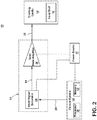
- FIG. 2 illustrates a schematic view of the microwave oven 10. While only one microwave generator 18 is illustrated for brevity, embodiments of the disclosure can include a plurality of microwave generators 18 operating in independently, as a common group with common respective outputs, or in a cohesive fashion wherein the plurality of microwave generators 18 operate to collectively provide the energy field utilized to heat or cook the foodstuff 16 in the cavity 14.
- the microwave generator 18 can include a small signal generator 24 configured to generate the radio frequency signal at a first power level, and a power amplifying device, such as a solid state radio frequency signal amplifier 26.
- the control system 22 can also include a processor 30 and memory 32. The control system 22 or the processor 30 can be configured to provide or supply a control signal 28, that is, an analog or digital communication signal, to the microwave generator 18 or the small signal generator 24.
- the memory 32 can include random access memory (RAM), read-only memory (ROM), flash memory, or one or more different types of portable electronic memory, such as discs, DVDs, CD-ROMs, etc., or any suitable combination of these types of memory.
- the control system 22 can be operably coupled with the memory 32 such that one of the control system 22 and the memory 32 can include all or a portion of a computer program having an executable instruction set for controlling the operation of the aforementioned components, or a method of operating the same.
- the program can include a computer program product that can include machine-readable media for carrying or having machine-executable instructions or data structures stored thereon. Such machine-readable media can be any available media, which can be accessed by a general purpose or special purpose computer or other machine with a processor.
- Such a computer program can include routines, programs, objects, components, data structures, algorithms, etc., that have the technical effect of performing particular tasks or implement particular abstract data types.
- Machine-executable instructions, associated data structures, and programs represent examples of program code for executing the exchange of information as disclosed herein.
- Machine-executable instructions can include, for example, instructions and data, which cause a general purpose computer, special purpose computer, control system 22, or special purpose processing machine to perform a certain function or group of functions.
- the functions can be converted to a computer program comprising a set of executable instructions, which can be executed by the processor 30.
- the control signal 28 can include a desired cooking signal representative of a heating or cooking energy field desired for heating or cooking the foodstuff 16.
- Embodiments of the control signal 28 can further include a desired cooking signal generated or selected, for example from a database, executable instruction set executed by the processor 30, look up table stored in memory 32, or the like, based at least partially on the foodstuff 16 to be heated or cooked.
- a user can select from a variety of foodstuff 16 settings or values on a user interface for heating or cooking cycles of operation tailored to a particular foodstuff 16.
- embodiments of the disclosure can include configurations wherein the control system 22 includes a user interface. Examples of tailored cooking cycles of operation can include, but is not limited to, a "defrost" selection, "popcorn” selection, "reheat” selection, "vegetables” selection, or the like.
- the control signal 28 can also include a desired cooking signal representative of a heating or cooking energy field characteristics desired heating or cooking of the foodstuff 16.
- the heating or cooking energy field characteristics of the control signal 28 can include, but is not limited to, a first power level desired, a second power level desired, a signal switching frequency, and the like.
- At least a subset of the aforementioned representative signals included in or carried by the control signal 28 can be configured, selected, or determined based on the foodstuff 16 to be heating or cooked, such as from a user interface as explained above.
- embodiments of the disclosure can include configurations wherein at least a subset of the aforementioned representative signals included in or carried by the control signal 28 can be configured, selected, or determined by executable software operated by the microwave oven 10, control system 22, or processor 30, or from a look up table stored in memory 32 and accessible by the control system 22 or processor 30.
- at least a subset of the aforementioned representative signals included in or carried by the control signal 28 can be configured, selected, or determined based on feedback or sensed characteristics of the foodstuff 16. Such feedback or sensed characteristics can be observer, sensed, or measured by way of a plurality of sensors, including, but not limited to, an optical sensor such as a camera, a steam or temperature sensor, or the like.
- the small signal generator 24 receives the control signal 28, and in response to the control signal 28 and included signal representative signals, generates a first radio frequency signal 34 at the first low power level.
- a "low" power level denotes a signal, power, or energy level below the energy field level utilized to heat or cook the foodstuff 16.
- the small signal generator 24 can be configured to generate a first radio frequency signal 34 with a power level at or greater than 150 milliWatts (mW).
- the small signal generator 24 can generate a first radio frequency signal 34 in response to the control signal 28, wherein the first radio frequency signal 34 is pulse width modulated at a predetermined switching frequency, wherein the predetermined switching frequency is defined, controlled, selected, or instructed by the signal switching frequency energy field characteristic of the control signal 28.
- Non-limiting embodiments of the disclosure can include wherein the predetermined switching frequency is at least 20 KHz, wherein the predetermined switching frequency is at least ten times faster than an inverse thermal time constant of the foodstuff 16 being heated or cooked, or a combination thereof.
- the predetermined switching frequency can be related to electrical regulations or practical power source 17 concerns regarding the predetermined switching on and off of the power, including flickering, modulation, power surges or deficiencies, and the like. It is understood that pulse width modulation signals can be configured to operably control, select, or limit an amount of energy field supplied to the cavity 14.
- first radio frequency signal 34 can include a first low power level of less than 1 Watt, such as 300 milliwatt.
- the first radio frequency signal 34 can be provided to the solid state amplifier 26.
- Solid state amplifiers 26 include the operably ability to be tunable and coherent, that is precisely controllable to amplify a specific signal, compared with a magnetron source that is not narrow band and not tunable (i.e. emits microwave signals at a changing frequency over time that is not precisely selectable).
- the solid state amplifier 26 can operably amplify the first radio frequency signal 34 having the first low power level to a second radio frequency signal 36 having a second high power level embodying the heating or cooking energy field utilized to heat or cook the foodstuff 16.
- the power level can be increased from the first low power level to the second high power level, and the predetermined switching frequency can be unchanged, or can remain constant through the power amplification process.
- One non-limiting embodiment of the second radio frequency signal 34 can include a second high power level of greater than 50 or 100 Watts, such as 250 Watts.
- the second high power level can also be described in terms of a gain, such as a 32 dB gain.
- the final output power of the energy field, for example from a plurality of microwave generators 18 can include 1000 Watts or more.
- solid state amplifier 26 While a single solid state amplifier 26 is illustrated for brevity, embodiments of the disclosure can include a plurality of solid state amplifiers 26, each amplifying a first radio frequency signal 34. Additionally, the solid state amplifier 26 can be selected such that the desired operable amplification for the microwave oven 10 occurs in the compression zone of the solid state device, for improved electrical performance and efficiency.
- the second radio frequency signal 36 can then be provided to the cavity 14, for example, by way of the feeding ports 20, wherein the energy field can interact with the foodstuff 16 to heat or cook the foodstuff 16, as desired.
- the power source 17 can be electrically coupled with the control system 22, the small signal generator 24, the solid state amplifier 26, or a combination thereof, to operably supply power to the respective components.
- the power supplied by the power source 17 can be utilized by the respective components to, for example, generate the control signal 28 in the control system 22, generate the first radio frequency signal 34 in the small signal generator 24, amplify the first radio frequency signal 34 to the second radio frequency signal 36 in the solid state amplifier 26, or a combination thereof.
- the food acts similar to a lowpass filter such that the measureable heating effect increases the cooking efficiency of the microwave. Additionally, the heating or cooking employed by the above-described embodiments can result in a more uniform or even temperature rise of the foodstuff 16, compared with conventional microwaves.
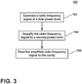
- FIG. 3 illustrates a flow chart demonstrating a method 100 of delivering radio frequency electromagnetic energy to cook foodstuff in an enclosed cavity of a cooking device, such as a microwave.
- the method 100 begins by generating, with the small signal generator 24, a radio frequency signal at a first power level that is pulse width modulated at a predetermined switching frequency at 102.
- the method 100 amplifies the radio frequency signal to a second power level, greater than the first power level, with the solid state amplifier 26 at 104.
- the method 100 feeds the amplified radio frequency signal to the enclosed cavity 14 at 106, wherein the amplified radio frequency signal operably heats or cooks the foodstuff 16 within the cavity 14.
- the embodiments disclosed herein provide a liquid cooling circuit for a heat-generating module.
- the technical effect is that the above described embodiments enable a method and apparatus for delivering radio frequency electromagnetic energy to cook foodstuff in a cooking device, such as a microwave.
- a cooking device such as a microwave.
- One advantage that can be realized in the above embodiments is that the above described embodiments have superior heating or cooking capabilities compared with conventional microwave systems.
- embodiments of the disclosure operating the energy field at a predetermined switching frequency of at least 20 KHz limit the flickering and power supply problems described above. Additionally, by operating the energy field at the predetermined switching frequency is at least ten times faster than an inverse thermal time constant of the foodstuff being heated or cooked, the measurable heating effects on the foodstuff are consistent over the cooking period.
Landscapes
- Physics & Mathematics (AREA)
- Electromagnetism (AREA)
- Electric Ovens (AREA)
- Control Of High-Frequency Heating Circuits (AREA)
- Electric Stoves And Ranges (AREA)
- Constitution Of High-Frequency Heating (AREA)
Description
- Current microwave cooking appliances use powerful tubes to generate microwaves with nominal operating frequencies to heat food. A disadvantage of using such powerful sources is a limited ability to control emission of the microwaves. Solid state sources enable specifying emissions that allow for a more controlled cooking appliance. Some solid state sourced microwave cooking appliance designs include determining a model of the cavity of the microwave, but do not allow for specified cooking strategies regarding the food within the cavity. There is a need to improve control of the emissions using solid state sources to achieve better heating for specific food items and more efficient appliances.
- A microwave cooking appliance according to the prior art is disclosed in
US2015/271877 . - In one aspect, a method of delivering radio frequency electromagnetic energy to cook foodstuff in an enclosed cavity of a cooking device includes generating, with a small signal generating component, a radio frequency signal at a first power level that is pulse width modulated at a predetermined switching frequency, amplifying the radio frequency signal to a second power level greater than the first power level with a radio frequency amplification component, and feeding the amplified radio frequency signal to the enclosed cavity. The predetermined switching frequency is at least 10 times faster than the inverse thermal time constant of the foodstuff being cooked.
- In another aspect, an apparatus for delivering radio frequency electromagnetic energy to cook foodstuff in a cooking device includes a cavity configured to hold a foodstuff to be cooked, a small signal generator to generate a radio frequency signal, a power amplifier connected to the small single generator to amplify the radio frequency signal generated by the small signal generator, a transmission line between the power amplifier and the enclosed cavity to feed the amplified radio frequency signal from the power amplifier to the enclosed cavity, and a controller configured to signal the small signal generator to generate the radio frequency signal at a first power level that is pulse width modulated at a predetermined switching frequency.
- In the drawings:
-
FIG. 1 is a schematic view of a cooking device in the embodiment of a microwave heating apparatus, in accordance with various aspects described herein. -
FIG. 2 is a schematic view of the microwave heating apparatus ofFIG. 1 , in accordance with various aspects described herein. -
FIG. 3 is an example a flow chart diagram of delivering radio frequency electromagnetic energy to cook foodstuff, in accordance with various aspects described herein. -
FIG. 1 illustrates a cooking device, shown as a microwave appliance ormicrowave oven 10, having ahousing 12 defining acavity 14 into which at least one food item, or "foodstuff" 16 (schematically shown as a box) can be placed. Themicrowave oven 10FIG. 1 is illustrated having anopen cavity 14 for ease of depiction of thefoodstuff 16, and embodiments of the disclosure can includemicrowaves 10 having an enclosedcavity 14, such as by way of a pivotable, movable, or removable panel, such as a door. Eachfoodstuff 16 will have a thermal time constant, which is generally defined as a measure of time for the temperature of the foodstuff to change from one temperature to another temperature in ambient conditions. For example, a thermal time constant can refer to a time-temperature dependency for a foodstuff at a given first temperature, greater than the ambient temperature in a space, to decrease or decay to the ambient temperature. In one non-limiting example, heated meat can have a thermal time constant near or between 100 to 120 seconds, wherein the temperature of the heated meat will decrease over that period of time to the ambient temperature. The thermal time constant can be related to a linearly decreasing time-temperature dependent function, a decreasing exponential function, or the like. - The
microwave oven 10 includes apower source 17 with an input range preferably ranging from less than 1 W to 250 W and at least onemicrowave generator 18, which is capable of generating a radio frequency electromagnetic energy field (hereafter, "energy field"), with an operating frequency preferably ranging from 2.401GHz to 2.48GHz. In an exemplary embodiment, themicrowave oven 10 can have two ormore microwave generators 18, wherein eachmicrowave generator 18 is electrically coupled with thepower source 17. Eachmicrowave generator 18 can include at least one antenna (not shown) adapted to provide the energy field generated by themicrowave generator 18, which is fed into thecavity 14 by way of at least onefeeding port 20 electrically coupled with eachmicrowave generator 18 by way of at least one conductor ortransmission line 21. - The
microwave oven 10 can also include acontrol system 22, communicatively coupled with themicrowave generators 18, thepower source 17, or a combination thereof, and programmed or configured to control the generation of the energy field by themicrowave generator 18. For example, thecontrol system 22 can operably control the power output of thepower source 17, the operation of the at least onemicrowave generator 18, or electromagnetic characteristics of the generated energy field, such as power level or frequency. In embodiments of the disclosure wherein at least twomicrowave generators 18 are utilized, thecontrol system 22 can further operably control the phase of the at least twomicrowave generators 18 to alter the interference pattern of the electromagnetic waves of the energy field. - During cooking or heating operations, the
control system 22 of themicrowave oven 10 operates to control the generation of the energy field by themicrowave generators 18 and to provide the energy field into thecavity 14 by way of thefeeding ports 20. The energy field interacts with thefood item 16 to heat or cook thefood item 16. The illustrated embodiment ofFIG. 1 is one non-limiting example of an embodiment of the disclosure. Additional non-limiting embodiments of the disclosure can include additional or alternatively located components, including but not limited to, themicrowave generators 18,feeding ports 20,control system 22,power source 17, or the like. -
FIG. 2 illustrates a schematic view of themicrowave oven 10. While only onemicrowave generator 18 is illustrated for brevity, embodiments of the disclosure can include a plurality ofmicrowave generators 18 operating in independently, as a common group with common respective outputs, or in a cohesive fashion wherein the plurality ofmicrowave generators 18 operate to collectively provide the energy field utilized to heat or cook thefoodstuff 16 in thecavity 14. As shown, themicrowave generator 18 can include asmall signal generator 24 configured to generate the radio frequency signal at a first power level, and a power amplifying device, such as a solid state radiofrequency signal amplifier 26. Thecontrol system 22 can also include aprocessor 30 andmemory 32. Thecontrol system 22 or theprocessor 30 can be configured to provide or supply acontrol signal 28, that is, an analog or digital communication signal, to themicrowave generator 18 or thesmall signal generator 24. - The
memory 32 can include random access memory (RAM), read-only memory (ROM), flash memory, or one or more different types of portable electronic memory, such as discs, DVDs, CD-ROMs, etc., or any suitable combination of these types of memory. Thecontrol system 22 can be operably coupled with thememory 32 such that one of thecontrol system 22 and thememory 32 can include all or a portion of a computer program having an executable instruction set for controlling the operation of the aforementioned components, or a method of operating the same. The program can include a computer program product that can include machine-readable media for carrying or having machine-executable instructions or data structures stored thereon. Such machine-readable media can be any available media, which can be accessed by a general purpose or special purpose computer or other machine with a processor. Generally, such a computer program can include routines, programs, objects, components, data structures, algorithms, etc., that have the technical effect of performing particular tasks or implement particular abstract data types. - Machine-executable instructions, associated data structures, and programs represent examples of program code for executing the exchange of information as disclosed herein. Machine-executable instructions can include, for example, instructions and data, which cause a general purpose computer, special purpose computer,
control system 22, or special purpose processing machine to perform a certain function or group of functions. In implementation, the functions can be converted to a computer program comprising a set of executable instructions, which can be executed by theprocessor 30. - The
control signal 28 can include a desired cooking signal representative of a heating or cooking energy field desired for heating or cooking thefoodstuff 16. Embodiments of thecontrol signal 28 can further include a desired cooking signal generated or selected, for example from a database, executable instruction set executed by theprocessor 30, look up table stored inmemory 32, or the like, based at least partially on thefoodstuff 16 to be heated or cooked. For example, a user can select from a variety offoodstuff 16 settings or values on a user interface for heating or cooking cycles of operation tailored to aparticular foodstuff 16. In this sense, embodiments of the disclosure can include configurations wherein thecontrol system 22 includes a user interface. Examples of tailored cooking cycles of operation can include, but is not limited to, a "defrost" selection, "popcorn" selection, "reheat" selection, "vegetables" selection, or the like. - The
control signal 28 can also include a desired cooking signal representative of a heating or cooking energy field characteristics desired heating or cooking of thefoodstuff 16. For example, the heating or cooking energy field characteristics of thecontrol signal 28 can include, but is not limited to, a first power level desired, a second power level desired, a signal switching frequency, and the like. At least a subset of the aforementioned representative signals included in or carried by thecontrol signal 28 can be configured, selected, or determined based on thefoodstuff 16 to be heating or cooked, such as from a user interface as explained above. Alternatively, embodiments of the disclosure can include configurations wherein at least a subset of the aforementioned representative signals included in or carried by thecontrol signal 28 can be configured, selected, or determined by executable software operated by themicrowave oven 10,control system 22, orprocessor 30, or from a look up table stored inmemory 32 and accessible by thecontrol system 22 orprocessor 30. In yet another embodiment of the disclosure, at least a subset of the aforementioned representative signals included in or carried by thecontrol signal 28 can be configured, selected, or determined based on feedback or sensed characteristics of thefoodstuff 16. Such feedback or sensed characteristics can be observer, sensed, or measured by way of a plurality of sensors, including, but not limited to, an optical sensor such as a camera, a steam or temperature sensor, or the like. - The
small signal generator 24 receives thecontrol signal 28, and in response to thecontrol signal 28 and included signal representative signals, generates a firstradio frequency signal 34 at the first low power level. As used herein, a "low" power level denotes a signal, power, or energy level below the energy field level utilized to heat or cook thefoodstuff 16. In a non-limiting example embodiment of the disclosure, thesmall signal generator 24 can be configured to generate a firstradio frequency signal 34 with a power level at or greater than 150 milliWatts (mW). In one embodiment of the disclosure, thesmall signal generator 24 can generate a firstradio frequency signal 34 in response to thecontrol signal 28, wherein the firstradio frequency signal 34 is pulse width modulated at a predetermined switching frequency, wherein the predetermined switching frequency is defined, controlled, selected, or instructed by the signal switching frequency energy field characteristic of thecontrol signal 28. - Non-limiting embodiments of the disclosure can include wherein the predetermined switching frequency is at least 20 KHz, wherein the predetermined switching frequency is at least ten times faster than an inverse thermal time constant of the
foodstuff 16 being heated or cooked, or a combination thereof. In another non-limiting embodiment of the disclosure the predetermined switching frequency can be related to electrical regulations orpractical power source 17 concerns regarding the predetermined switching on and off of the power, including flickering, modulation, power surges or deficiencies, and the like. It is understood that pulse width modulation signals can be configured to operably control, select, or limit an amount of energy field supplied to thecavity 14. Another non-limiting embodiment firstradio frequency signal 34 can include a first low power level of less than 1 Watt, such as 300 milliwatt. - The first
radio frequency signal 34 can be provided to thesolid state amplifier 26.Solid state amplifiers 26 include the operably ability to be tunable and coherent, that is precisely controllable to amplify a specific signal, compared with a magnetron source that is not narrow band and not tunable (i.e. emits microwave signals at a changing frequency over time that is not precisely selectable). Thesolid state amplifier 26 can operably amplify the firstradio frequency signal 34 having the first low power level to a secondradio frequency signal 36 having a second high power level embodying the heating or cooking energy field utilized to heat or cook thefoodstuff 16. During amplification by thesolid state amplifier 26, the power level can be increased from the first low power level to the second high power level, and the predetermined switching frequency can be unchanged, or can remain constant through the power amplification process. One non-limiting embodiment of the secondradio frequency signal 34 can include a second high power level of greater than 50 or 100 Watts, such as 250 Watts. The second high power level can also be described in terms of a gain, such as a 32 dB gain. The final output power of the energy field, for example from a plurality ofmicrowave generators 18 can include 1000 Watts or more. - While a single
solid state amplifier 26 is illustrated for brevity, embodiments of the disclosure can include a plurality ofsolid state amplifiers 26, each amplifying a firstradio frequency signal 34. Additionally, thesolid state amplifier 26 can be selected such that the desired operable amplification for themicrowave oven 10 occurs in the compression zone of the solid state device, for improved electrical performance and efficiency. - The second
radio frequency signal 36 can then be provided to thecavity 14, for example, by way of the feedingports 20, wherein the energy field can interact with thefoodstuff 16 to heat or cook thefoodstuff 16, as desired. As illustrated, thepower source 17 can be electrically coupled with thecontrol system 22, thesmall signal generator 24, thesolid state amplifier 26, or a combination thereof, to operably supply power to the respective components. The power supplied by thepower source 17 can be utilized by the respective components to, for example, generate thecontrol signal 28 in thecontrol system 22, generate the firstradio frequency signal 34 in thesmall signal generator 24, amplify the firstradio frequency signal 34 to the secondradio frequency signal 36 in thesolid state amplifier 26, or a combination thereof. - When
foodstuff 16 is heated or cooked by operably utilizing such a high predetermined switching frequency, the food acts similar to a lowpass filter such that the measureable heating effect increases the cooking efficiency of the microwave. Additionally, the heating or cooking employed by the above-described embodiments can result in a more uniform or even temperature rise of thefoodstuff 16, compared with conventional microwaves. -
FIG. 3 illustrates a flow chart demonstrating amethod 100 of delivering radio frequency electromagnetic energy to cook foodstuff in an enclosed cavity of a cooking device, such as a microwave. Themethod 100 begins by generating, with thesmall signal generator 24, a radio frequency signal at a first power level that is pulse width modulated at a predetermined switching frequency at 102. Next, themethod 100 amplifies the radio frequency signal to a second power level, greater than the first power level, with thesolid state amplifier 26 at 104. Finally, themethod 100 feeds the amplified radio frequency signal to theenclosed cavity 14 at 106, wherein the amplified radio frequency signal operably heats or cooks thefoodstuff 16 within thecavity 14. The sequence depicted is for illustrative purposes only and is not meant to limit themethod 100 in any way as it is understood that the portions of the method can proceed in a different logical order, additional or intervening portions can be included, or described portions of the method can be divided into multiple portions, or described portions of the method can be omitted without detracting from the described method. - Many other possible embodiments and configurations in addition to that shown in the above figures are contemplated by the present disclosure.
- The embodiments disclosed herein provide a liquid cooling circuit for a heat-generating module. The technical effect is that the above described embodiments enable a method and apparatus for delivering radio frequency electromagnetic energy to cook foodstuff in a cooking device, such as a microwave. One advantage that can be realized in the above embodiments is that the above described embodiments have superior heating or cooking capabilities compared with conventional microwave systems. For example, embodiments of the disclosure operating the energy field at a predetermined switching frequency of at least 20 KHz limit the flickering and power supply problems described above. Additionally, by operating the energy field at the predetermined switching frequency is at least ten times faster than an inverse thermal time constant of the foodstuff being heated or cooked, the measurable heating effects on the foodstuff are consistent over the cooking period. Compare this with the heating effects while cooking foodstuff with a conventional microwave, wherein the significantly longer or slower switching periods (on the order of seconds) produce measureable heating effects followed by a sudden temperature decrease as the energy field is shut down, producing undesirable cooking temperature oscillations. The aforementioned oscillations in cooking temperature reduce the effective cooking efficiency or performance of the microwave.
- To the extent not already described, the different features and structures of the various embodiments can be used in combination with each other as desired. That one feature cannot be illustrated in all of the embodiments is not meant to be construed that it cannot be, but is done for brevity of description. Thus, the various features of the different embodiments can be mixed and matched as desired to form new embodiments, whether or not the new embodiments are expressly described. Moreover, while "a set of' or "a plurality of' various elements have been described, it will be understood that "a set" or "a plurality" can include any number of the respective elements, including only one element. Combinations or permutations of features described herein are covered by this disclosure.
- This written description uses examples to disclose embodiments of the invention, including the best mode, and also to enable any person skilled in the art to practice embodiments of the invention, including making and using any devices or systems and performing any incorporated methods. The patentable scope of the invention is defined by the claims, and can include other examples that occur to those skilled in the art. Such other examples are intended to be within the scope of the claims if they have structural elements that do not differ from the literal language of the claims, or if they include equivalent structural elements with insubstantial differences from the literal languages of the claims.
Claims (15)
- A method of delivering radio frequency electromagnetic energy to cook foodstuff (16) in an enclosed cavity (14) of a cooking device (10), the method comprising:generating, with a small signal generating component (24), a radio frequency signal at a first power level that is pulse width modulated at a predetermined switching frequency;amplifying the radio frequency signal to a second power level greater than the first power level with a radio frequency amplification component; andfeeding the amplified radio frequency signal to the enclosed cavity;wherein the predetermined switching frequency is at least 10 times faster than the inverse thermal time constant of the foodstuff being cooked.
- The method of claim 1 wherein the predetermined switching frequency is at least 20 KHz.
- The method of claim 1 wherein the first power level is less than 1 Watt.
- The method of claim 1 wherein the second power level is greater than 50 Watts.
- The method of claim 1 wherein the predetermined switching frequency is determined from a look up table.
- The method of claim 1 wherein the predetermined switching frequency is determined based on feedback from the foodstuff.
- An apparatus for delivering radio frequency electromagnetic energy to cook foodstuff in a cooking device comprising:a cavity configured to hold a foodstuff to be cooked;a small signal generator to generate a radio frequency signal;a power amplifier (26) connected to the small single generator to amplify the radio frequency signal generated by the small signal generator;a transmission line between the power amplifier and the enclosed cavity to feed the amplified radio frequency signal from the power amplifier to the enclosed cavity; anda controller (22) configured to signal the small signal generator to generate the radio frequency signal at a first power level characterised in that the radio frequency signal is pulse width modulated at a predetermined switching frequency.
- The apparatus of claim 7 wherein the predetermined switching frequency is at least 20 KHz.
- The apparatus of claim 7 wherein the first power level is less than 1 Watt.
- The apparatus of claim 7 wherein the second power level is greater than 50 Watts.
- The apparatus of claim 7 wherein the predetermined switching frequency is determined from a look up table.
- The apparatus of claim 7 wherein the predetermined switching frequency is determined based on feedback from the foodstuff.
- The apparatus of claim 7 wherein the small signal generator is configured to generate the radio frequency signal having a power level greater than 150 milliWatts.
- The apparatus of claim 7 wherein the power amplifier is configured to amplify the radio frequency signal such that the amplified radio frequency signal has a power level greater than 50 Watts.
- The apparatus of claim 7 further comprising memory coupled to the controller holding data from which to set the predetermined switching frequency.
Applications Claiming Priority (1)
| Application Number | Priority Date | Filing Date | Title |
|---|---|---|---|
| PCT/US2016/017960 WO2017142503A1 (en) | 2016-02-15 | 2016-02-15 | Method and apparatus for delivering radio frequency electromagnetic energy to cook foodstuff |
Publications (2)
| Publication Number | Publication Date |
|---|---|
| EP3417675A1 EP3417675A1 (en) | 2018-12-26 |
| EP3417675B1 true EP3417675B1 (en) | 2020-03-18 |
Family
ID=55521809
Family Applications (1)
| Application Number | Title | Priority Date | Filing Date |
|---|---|---|---|
| EP16709189.1A Revoked EP3417675B1 (en) | 2016-02-15 | 2016-02-15 | Method and apparatus for delivering radio frequency electromagnetic energy to cook foodstuff |
Country Status (5)
| Country | Link |
|---|---|
| US (1) | US10827570B2 (en) |
| EP (1) | EP3417675B1 (en) |
| JP (1) | JP6775027B2 (en) |
| CN (1) | CN108702817B (en) |
| WO (1) | WO2017142503A1 (en) |
Citations (2)
| Publication number | Priority date | Publication date | Assignee | Title |
|---|---|---|---|---|
| WO2015099651A1 (en) | 2013-12-23 | 2015-07-02 | Whirlpool Corporation | Method of calibrating a multifeed radio frequency device |
| WO2017131698A1 (en) | 2016-01-28 | 2017-08-03 | Whirlpool Corporation | Method and apparatus for delivering radio frequency electromagnetic energy to cook foodstuff |
Family Cites Families (252)
| Publication number | Priority date | Publication date | Assignee | Title |
|---|---|---|---|---|
| GB639470A (en) | 1946-08-27 | 1950-06-28 | Jiri Stivin | A device for repeated starting and stopping of an oscillation generator |
| US2742612A (en) | 1950-10-24 | 1956-04-17 | Sperry Rand Corp | Mode transformer |
| US2956143A (en) | 1958-06-05 | 1960-10-11 | Raytheon Co | Microwave ovens |
| US2958754A (en) | 1958-12-15 | 1960-11-01 | Gen Electric | Electronic ovens |
| US2981904A (en) | 1959-01-06 | 1961-04-25 | Hughes Aircraft Co | Microwave transition device |
| US3260832A (en) | 1963-10-28 | 1966-07-12 | Westinghouse Electric Corp | Oven |
| US3265995A (en) | 1964-03-18 | 1966-08-09 | Bell Telephone Labor Inc | Transmission line to waveguide junction |
| US3440385A (en) | 1965-10-13 | 1969-04-22 | Microtherm Ltd | Electronic ovens |
| US3430023A (en) | 1967-09-11 | 1969-02-25 | Roper Corp Geo D | Door construction and ventilating system for microwave oven |
| US3489135A (en) | 1968-06-21 | 1970-01-13 | Indian Head Inc | Oven door construction |
| US3536129A (en) | 1968-11-19 | 1970-10-27 | Varian Associates | Method for thawing frozen water-bearing substances utilizing microwave energy |
| US3639717A (en) | 1970-09-08 | 1972-02-01 | Mitsubishi Electric Corp | Switch actuator for an electronic cooking device |
| US3731035A (en) | 1971-11-15 | 1973-05-01 | Litton Systems Inc | Microwave oven door |
| DE2320438A1 (en) | 1972-06-26 | 1974-01-10 | Litton Industries Inc | MICROWAVE OVEN |
| US3737812A (en) | 1972-09-08 | 1973-06-05 | Us Navy | Broadband waveguide to coaxial line transition |
| US3812316A (en) | 1973-03-28 | 1974-05-21 | Gen Electric | Door seal gasket for combined microwave and self-cleaning oven |
| US4000390A (en) | 1975-02-14 | 1976-12-28 | Hobart Corporation | Microwave oven door |
| US4136271A (en) | 1976-02-03 | 1979-01-23 | Matsushita Electric Industrial Co., Ltd. | Microwave oven |
| US4088861A (en) | 1976-03-18 | 1978-05-09 | Mcgraw-Edison Company | Microwave oven with torsion bar hinge |
| JPS52121838A (en) | 1976-04-06 | 1977-10-13 | Matsushita Electric Ind Co Ltd | High frequency heating device |
| FR2359522A1 (en) | 1976-07-20 | 1978-02-17 | Thomson Csf | TRANSITION BETWEEN A COAXIAL LINE AND A WAVE GUIDE, AND HYPERFREQUENCY CIRCUITS INCLUDING SUCH A TRANSITION |
| USD248607S (en) | 1976-11-19 | 1978-07-25 | Matsushita Electric Industrial Co., Ltd. | Microwave oven |
| US4101750A (en) | 1977-05-31 | 1978-07-18 | Whirlpool Corporation | Door interlock system for microwave oven |
| US4166207A (en) | 1977-05-31 | 1979-08-28 | Whirlpool Corporation | Microwave generating device--door seal |
| US4143646A (en) | 1977-10-27 | 1979-03-13 | Home Metal Products Company A Division Of Mobex Corporation | Cooking apparatus and exhaust system |
| CA1081796A (en) | 1978-02-09 | 1980-07-15 | B. Alejandro Mackay | Controlled heating microwave ovens using different operating frequencies |
| US4283614A (en) | 1978-02-20 | 1981-08-11 | Matsushita Electric Industrial Co., Ltd. | Cooking device with high-frequency heating means and resistance heating means |
| JPS55155120A (en) | 1979-05-18 | 1980-12-03 | Sanyo Electric Co Ltd | Electronic control type cooker |
| US4264800A (en) | 1979-06-08 | 1981-04-28 | Minnesota Mining And Manufacturing Company | Microwave oven window |
| US4374319A (en) | 1979-11-27 | 1983-02-15 | Sunset Ltd. | Counter-top oven |
| US4321445A (en) | 1980-01-28 | 1982-03-23 | Whirlpool Corporation | Door latch interlock system for microwave oven |
| USD268079S (en) | 1980-02-04 | 1983-03-01 | Sharp Corporation | Microwave oven |
| US4354562A (en) | 1980-12-03 | 1982-10-19 | Newman Martin H | Electronic weighing device |
| JPS57194296U (en) | 1981-06-04 | 1982-12-09 | ||
| US4463324A (en) | 1982-06-03 | 1984-07-31 | Sperry Corporation | Miniature coaxial line to waveguide transition |
| USD275546S (en) | 1982-07-08 | 1984-09-18 | Matsushita Electric Industrial Co., Ltd. | Microwave oven |
| USD276122S (en) | 1982-07-08 | 1984-10-30 | Matsushita Electric Industrial Co., Ltd. | Microwave oven |
| DE3238441A1 (en) | 1982-10-16 | 1984-04-19 | Licentia Patent-Verwaltungs-Gmbh, 6000 Frankfurt | Baking and roasting oven |
| USD285893S (en) | 1982-12-28 | 1986-09-30 | Matsushita Electric Industrial Co. | Front panel for a microwave oven |
| USD277355S (en) | 1982-12-30 | 1985-01-29 | Sharp Kabushiki Kaisha | Microwave oven |
| JPS59226497A (en) | 1983-06-06 | 1984-12-19 | 松下電器産業株式会社 | High frequency heater |
| USD297800S (en) | 1983-10-31 | 1988-09-27 | Bosch-Siemens Hausgerate Gmbh | Compact oven |
| WO1985003115A1 (en) | 1984-01-05 | 1985-07-18 | Matsushita Electric Industrial Co., Ltd. | Cooker with weight-detecting function |
| US4628351A (en) | 1984-04-23 | 1986-12-09 | Samsung Electronics Co., Ltd. | Cooking apparatus with a video display |
| US4786774A (en) | 1984-04-27 | 1988-11-22 | Sharp Kabushiki Kaisha | Combination compact microwave oven and ventilator system |
| DE8413224U1 (en) | 1984-04-30 | 1984-08-16 | Licentia Patent-Verwaltungs-Gmbh, 6000 Frankfurt | DOOR FOR THE BAKING AND FRYING ROOM OF A COOKING OVEN |
| US4595827A (en) | 1984-05-02 | 1986-06-17 | Matsushita Electric Industrial Co., Ltd. | Cooking apparatus with weighing device |
| USD297698S (en) | 1984-12-26 | 1988-09-20 | Imanishi Kinzoku Kogyo Kabushiki Kaisha | Microwave oven |
| CA1253923A (en) | 1985-04-15 | 1989-05-09 | Ichiroh Hori | High frequency heating apparatus with electric heating device |
| AU97420S (en) | 1986-04-22 | 1987-08-13 | Sharp Kk | Microwave oven |
| US4743728A (en) | 1986-05-31 | 1988-05-10 | Kabushiki Kaisha Toshiba | Dual path air circulation system for microwave ovens |
| GB8618218D0 (en) | 1986-07-25 | 1986-09-03 | Magnetronics Ltd | Edible product manufacture |
| DE3710796A1 (en) | 1987-03-31 | 1988-10-13 | Miele & Cie | MICROWAVE OVEN WITH A TURNTABLE |
| US4870238A (en) | 1987-10-26 | 1989-09-26 | Hodgetts Michael J | Microwave oven popcorn control |
| US4937413A (en) | 1987-10-26 | 1990-06-26 | Microwave Products Of America, Inc. | Acoustic sensor assembly for a microwave oven |
| US4886046A (en) | 1987-10-26 | 1989-12-12 | Whirlpool Corporation | Motor control circuit for an eye level range |
| CA1318014C (en) | 1989-07-06 | 1993-05-18 | Kevin Smith | Sealing enclosures against electromagnetic interference |
| JPH0395316A (en) * | 1989-09-07 | 1991-04-19 | Matsushita Electric Ind Co Ltd | High frequency heating device |
| US5075525A (en) | 1990-06-25 | 1991-12-24 | Goldstar Co., Ltd. | Wave shielding device for microwave oven |
| US6097019A (en) | 1990-07-11 | 2000-08-01 | International Business Machines Corporation | Radiation control system |
| US6054696A (en) | 1997-01-06 | 2000-04-25 | International Business Machines Corporation | Feedback system to automatically couple microwave energy into an applicator |
| KR950003405B1 (en) | 1990-07-25 | 1995-04-12 | 마쯔시다덴기산교 가부시기가이샤 | High frequency heating equipment |
| USD330144S (en) | 1990-07-31 | 1992-10-13 | Matsushita Electric Industrial Co., Ltd. | Microwave oven |
| JP2987470B2 (en) | 1991-07-05 | 1999-12-06 | 株式会社日立ホームテック | Cooking device |
| KR0115015Y1 (en) * | 1991-09-19 | 1998-10-01 | 이헌조 | Switching driving circuit |
| AU118758S (en) | 1992-07-21 | 1993-11-11 | Sharp Kk | Microwave oven |
| JPH06147492A (en) | 1992-11-17 | 1994-05-27 | Matsushita Electric Ind Co Ltd | High frequency heater |
| KR950002891Y1 (en) | 1993-01-12 | 1995-04-17 | 주식회사 금성사 | Weight sensor for microwave oven |
| FR2705765B1 (en) | 1993-04-29 | 1995-08-18 | Eurofours Sa | Oven door. |
| US5483045A (en) | 1994-06-09 | 1996-01-09 | Electric Power Research Institute | Microwave power system and method with exposure protection |
| DE4431619A1 (en) | 1994-09-05 | 1996-03-07 | Bosch Siemens Hausgeraete | Stove door of a cooker |
| JPH08171986A (en) | 1994-12-19 | 1996-07-02 | Hitachi Ltd | Microwave heating equipment |
| FR2732097B1 (en) | 1995-03-24 | 1997-05-23 | Seb Sa | SIMPLIFIED OVEN DOOR WITH REMOVABLE MODULE |
| US5619983A (en) | 1995-05-05 | 1997-04-15 | Middleby Marshall, Inc. | Combination convection steamer oven |
| US5558800A (en) | 1995-06-19 | 1996-09-24 | Northrop Grumman | Microwave power radiator for microwave heating applications |
| ES2110904B1 (en) | 1995-07-17 | 1998-10-01 | Montserrat Gibernau Antonio | PACKAGED FOOD PRODUCTS VENDING MACHINE. |
| KR0171337B1 (en) | 1995-09-18 | 1999-05-01 | 배순훈 | Microwave shielding structure for microwave oven door |
| KR100218958B1 (en) | 1996-02-23 | 1999-09-01 | 윤종용 | Tray control method for microwave oven |
| USD385155S (en) | 1996-05-23 | 1997-10-21 | White Consolidated Industries, Inc. | Microwave oven front panel |
| FR2751055B1 (en) | 1996-07-15 | 1998-09-25 | Moulinex Sa | ELECTRIC COOKING OVEN |
| USD378723S (en) | 1996-11-06 | 1997-04-08 | White Consolidated Industries, Inc. | Microwave oven |
| US5981929A (en) | 1996-12-20 | 1999-11-09 | Matsushita Electric Industrial Co., Ltd. | Heating cooker with a space-efficient ventilating arrangement |
| CA2229951C (en) | 1997-03-18 | 2002-05-07 | Sanyo Electric Co., Ltd. | Cooking apparatus including infrared ray sensor |
| RU2122338C1 (en) | 1997-04-08 | 1998-11-27 | Георгий Галиуллович Валеев | Food preparing apparatus |
| FR2766272B1 (en) | 1997-07-15 | 1999-10-15 | Moulinex Sa | DEVICE AND METHOD FOR MICROWAVE REFLECTOMETRY, AND MICROWAVE OVEN THUS EQUIPPED |
| AU136256S (en) | 1997-12-22 | 1999-01-19 | Sharp Kk | Microwave oven |
| US6097018A (en) | 1998-04-06 | 2000-08-01 | Lg Electronics Inc. | Circular polarization generating system for microwave oven |
| KR100284548B1 (en) | 1998-06-16 | 2001-05-02 | 윤종용 | Installation Structure of Hood Fan for Microwave Oven |
| US6359270B1 (en) | 1998-09-04 | 2002-03-19 | Ncr Corporation | Communications module mounting for domestic appliance |
| KR100341288B1 (en) | 1998-11-11 | 2002-10-25 | 삼성전자 주식회사 | Microwave oven to prevent overcurrent of microswitch that interrupts DC power |
| DE69935164T2 (en) * | 1998-12-17 | 2007-10-31 | Biotage Ab | MICROWAVE DEVICE AND METHOD FOR PERFORMING CHEMICAL REACTIONS |
| US6559882B1 (en) | 1999-09-02 | 2003-05-06 | Ncr Corporation | Domestic appliance |
| JP3620818B2 (en) | 1999-04-16 | 2005-02-16 | 株式会社三協精機製作所 | Weight detector and microwave oven |
| JP3485846B2 (en) | 1999-10-29 | 2004-01-13 | 三洋電機株式会社 | Cooking device |
| US6853399B1 (en) | 2000-05-26 | 2005-02-08 | Robert A. Gilman | Kitchen appliance with video display |
| GB2367196B (en) | 2000-07-27 | 2002-09-25 | Samsung Electronics Co Ltd | Microwave oven having a switching power supply |
| US6429370B1 (en) | 2000-08-31 | 2002-08-06 | Avaya Technology Corp. | Self-adhering electromagnetic interference door seal |
| ES2233264T3 (en) | 2000-09-29 | 2005-06-16 | Whirlpool Corporation | COOKING SYSTEM AND OVEN USED IN THE. |
| ES2272664T3 (en) | 2001-02-13 | 2007-05-01 | Arcelik A.S. | HOUSEHOLD APPLIANCE. |
| US7111247B2 (en) | 2001-07-02 | 2006-09-19 | Lg Electronics Inc. | Device and method for controlling menu display of microwave oven |
| US6696678B2 (en) | 2001-11-14 | 2004-02-24 | General Electric Company | Over turntable apparatus |
| WO2003077299A1 (en) | 2002-03-08 | 2003-09-18 | Tokyo Electron Limited | Plasma device |
| US6984811B2 (en) | 2002-03-11 | 2006-01-10 | Lg Electronics, Inc. | Door for microwave oven having integrally formed control unit |
| EP2405711B1 (en) | 2002-06-26 | 2015-05-06 | Mitsui Engineering and Shipbuilding Co, Ltd. | Induction heating method and unit |
| RU2003111214A (en) | 2002-07-02 | 2004-11-20 | Эл Джи Электроникс Инк. | DEVICE CONTAINING FURNACE AND RADIO RECEIVER, METHOD FOR TURNING OFF THE OPERATION OF THE RADIO RECEIVER, WHEN INCLUDE THE FURNACE, RADIO RECEIVER - MICROWAVE (OPTION) |
| US20040074760A1 (en) * | 2002-10-17 | 2004-04-22 | Carnegie Mellon University | Production of biofuels |
| US7105787B2 (en) | 2002-10-29 | 2006-09-12 | Fiore Industries, Inc. | Reverberating adaptive microwave-stirred exposure system |
| KR20040047083A (en) | 2002-11-29 | 2004-06-05 | 삼성전자주식회사 | Microwave oven and control method thereof |
| DE10256624B4 (en) | 2002-12-03 | 2005-12-08 | Miele & Cie. Kg | microwave oven |
| USD495556S1 (en) | 2002-12-09 | 2004-09-07 | Bsh Home Appliances Corporation | Range |
| DE10307217B4 (en) | 2003-02-20 | 2006-04-13 | Schott Ag | Door with viewing window for microwave ovens |
| USD481582S1 (en) | 2003-03-25 | 2003-11-04 | Whirlpool Corporation | Countertop oven |
| US20040206755A1 (en) | 2003-04-18 | 2004-10-21 | Hadinger Peter James | Microwave heating using distributed semiconductor sources |
| WO2004098241A1 (en) | 2003-04-25 | 2004-11-11 | Matsushita Electric Industrial Co., Ltd. | High-frequency heating device and method for controlling same |
| CN101158482B (en) | 2003-05-15 | 2012-02-01 | 松下电器产业株式会社 | High-frequency heating device |
| KR20050002121A (en) | 2003-06-30 | 2005-01-07 | 주식회사 대우일렉트로닉스 | Microwave Oven Having Function Of Automatically Cooking Popcorn And Method Thereof |
| EP1644665B1 (en) | 2003-07-16 | 2014-11-19 | LG Electronics, Inc. | Door opening and closing system for an electric oven |
| RU2253193C2 (en) | 2003-07-21 | 2005-05-27 | Санкт-Петербургский государственный университет | Microwave oven and method for optimizing its design characteristics |
| KR100577196B1 (en) | 2003-12-02 | 2006-05-10 | 엘지전자 주식회사 | Microwave oven with coffee maker and control method |
| DE102004002466A1 (en) | 2004-01-16 | 2005-08-11 | BSH Bosch und Siemens Hausgeräte GmbH | Oven door rests within an outer frame with two clip retainers embracing an anchorage block and hinge |
| CN1332082C (en) * | 2004-04-19 | 2007-08-15 | 陈新谋 | Graphitization preparation process for carbon fiber by using radio frequency method and production system thereof |
| JP2006010122A (en) | 2004-06-23 | 2006-01-12 | Matsushita Electric Ind Co Ltd | High-frequency heating device with range hood |
| US7193195B2 (en) | 2004-07-01 | 2007-03-20 | Whirlpool Corporation | Wall mounted microwave oven having a top vent with filter system |
| AU305036S (en) | 2004-10-04 | 2006-01-18 | Lg Electronics Inc | Microwave oven |
| USD530973S1 (en) | 2004-10-29 | 2006-10-31 | Lg Electronics Inc. | Microwave oven |
| USD531447S1 (en) | 2004-10-29 | 2006-11-07 | Lg Electronics Inc. | Microwave oven |
| USD527572S1 (en) | 2005-03-11 | 2006-09-05 | Lg Electronics Inc. | Oven |
| USD521799S1 (en) | 2005-03-18 | 2006-05-30 | Whirlpool Corporation | Countertop oven |
| USD540105S1 (en) | 2005-03-24 | 2007-04-10 | Lg Electronics Inc. | Microwave oven |
| USD532645S1 (en) | 2005-03-24 | 2006-11-28 | Lg Electronics Inc. | Microwave oven |
| KR20060128372A (en) | 2005-06-10 | 2006-12-14 | 삼성전자주식회사 | Oven |
| US7476828B2 (en) | 2005-06-10 | 2009-01-13 | Marc Genua | Media microwave oven |
| DE102005028253B3 (en) | 2005-06-17 | 2006-11-02 | Emz-Hanauer Gmbh & Co. Kgaa | Device and method to detect movement in a rotating component of a household appliance caused by imbalance has movable mass spring and damper with mass moving outwards above a given imbalance frequency |
| EP1795814A3 (en) | 2005-12-06 | 2011-01-26 | LG Electronics Inc. | Electric oven |
| US7770985B2 (en) | 2006-02-15 | 2010-08-10 | Maytag Corporation | Kitchen appliance having floating glass panel |
| US8653482B2 (en) | 2006-02-21 | 2014-02-18 | Goji Limited | RF controlled freezing |
| US10674570B2 (en) | 2006-02-21 | 2020-06-02 | Goji Limited | System and method for applying electromagnetic energy |
| CA117670S (en) | 2006-06-29 | 2007-10-24 | Sharp Kk | Oven |
| CN101118425A (en) | 2006-08-01 | 2008-02-06 | 上海中策工贸有限公司 | Nutrition processing system |
| JP5064924B2 (en) * | 2006-08-08 | 2012-10-31 | パナソニック株式会社 | Microwave processing equipment |
| CN2935699Y (en) * | 2006-08-08 | 2007-08-15 | 惕姆·弗兰克 | Portable AC and DC Inverter Microwave Oven |
| JP2008060017A (en) * | 2006-09-04 | 2008-03-13 | Matsushita Electric Ind Co Ltd | Microwave equipment |
| USD550024S1 (en) | 2006-09-15 | 2007-09-04 | Samsung Electronics Co., Ltd. | Electronic oven |
| USD540613S1 (en) | 2006-09-15 | 2007-04-17 | Samsung Electronics Co., Ltd. | Electronic oven |
| JP4967600B2 (en) | 2006-10-24 | 2012-07-04 | パナソニック株式会社 | Microwave processing equipment |
| KR101291426B1 (en) | 2007-01-02 | 2013-07-30 | 엘지전자 주식회사 | Microwave range having hood |
| EP2127481A1 (en) | 2007-02-21 | 2009-12-02 | RF Dynamics Ltd. | Rf controlled freezing |
| EP2127482B1 (en) | 2007-02-21 | 2014-04-23 | Goji Limited | Drying apparatus and method |
| DE102007012378A1 (en) | 2007-03-14 | 2008-09-18 | BSH Bosch und Siemens Hausgeräte GmbH | Domestic appliance, especially oven |
| US9131543B2 (en) | 2007-08-30 | 2015-09-08 | Goji Limited | Dynamic impedance matching in RF resonator cavity |
| EP2031937B1 (en) | 2007-09-03 | 2010-01-27 | Electrolux Home Products Corporation N.V. | A microwave oven door with a wave chokes system |
| EP2031939B1 (en) | 2007-09-03 | 2013-02-27 | Electrolux Home Products Corporation N.V. | A wave choke device for a microwave oven door |
| EP2031938B1 (en) | 2007-09-03 | 2013-02-27 | Electrolux Home Products Corporation N.V. | A wave choke system for a microwave oven door |
| CN201081287Y (en) | 2007-09-12 | 2008-07-02 | 广东格兰仕集团有限公司 | Hot air convection microwave oven with steam function |
| US8236144B2 (en) | 2007-09-21 | 2012-08-07 | Rf Thummim Technologies, Inc. | Method and apparatus for multiple resonant structure process and reaction chamber |
| KR101495378B1 (en) | 2007-10-18 | 2015-02-24 | 파나소닉 주식회사 | Microwave heating device |
| KR101450879B1 (en) | 2007-11-28 | 2014-10-14 | 엘지전자 주식회사 | A vent grill |
| JP2009156546A (en) | 2007-12-27 | 2009-07-16 | Panasonic Corp | Cooker |
| AU320419S (en) | 2008-03-28 | 2008-07-29 | Breville R & D Pty Ltd | Toaster oven |
| KR101004863B1 (en) | 2008-04-01 | 2010-12-28 | 엘지전자 주식회사 | Microwave |
| RU2390096C2 (en) | 2008-04-21 | 2010-05-20 | Государственное образовательное учреждение высшего профессионального образования Академия Федеральной службы охраны Российской Федерации (Академия ФСО России) | Method for assignment of frequencies to radio-electronic facilities |
| US8927913B2 (en) | 2008-06-30 | 2015-01-06 | The Invention Science Fund I, Llc | Microwave processing systems and methods |
| US8610038B2 (en) | 2008-06-30 | 2013-12-17 | The Invention Science Fund I, Llc | Microwave oven |
| USD586619S1 (en) | 2008-08-07 | 2009-02-17 | Sunbeam Products, Inc. | Toaster oven |
| JP5358580B2 (en) | 2008-09-17 | 2013-12-04 | パナソニック株式会社 | Microwave heating device |
| RU2393650C2 (en) | 2008-09-22 | 2010-06-27 | Валерий Степанович Жилков | Microwave oven |
| USD602306S1 (en) | 2008-09-25 | 2009-10-20 | Danny Lavy | Toaster oven |
| DE102008042467A1 (en) | 2008-09-30 | 2010-04-01 | BSH Bosch und Siemens Hausgeräte GmbH | Door for cooking chamber of baking-oven, has intermediate space blocked in counter bearings by clamping forces, and spring element supported at door front and provided for tensioning intermediate space and inner pane |
| ES2394919T3 (en) | 2008-11-10 | 2013-02-06 | Goji Limited | Device and method to control energy |
| WO2010118267A1 (en) | 2009-04-08 | 2010-10-14 | Accelbeam Devices Llc | Microwave processing chamber |
| USD625557S1 (en) | 2009-06-16 | 2010-10-19 | Sunbeam Products, Inc. | Countertop oven |
| AU327596S (en) | 2009-08-19 | 2009-09-11 | Breville R & D Pty Ltd | Toaster oven |
| USD626370S1 (en) | 2009-08-27 | 2010-11-02 | Sumsung Electronics Co., Ltd. | Microwave oven |
| CN102484910B (en) | 2009-09-16 | 2014-07-09 | 松下电器产业株式会社 | Microwave heating device |
| US8796593B2 (en) | 2009-09-29 | 2014-08-05 | Panasonic Corporation | Radio-frequency heating apparatus and radio-frequency heating method |
| ES2534411T3 (en) | 2009-11-10 | 2015-04-22 | Goji Limited | Device and method for energy control |
| EP2326141B1 (en) | 2009-11-18 | 2012-12-26 | Whirlpool Corporation | Microwave oven and related method including a magnetron for heating and a SSMG for heated objects sensing |
| EP2512206A4 (en) | 2009-12-09 | 2013-11-13 | Panasonic Corp | APPARATUS AND METHOD FOR HEATING BY HIGH FREQUENCY |
| US8745203B2 (en) | 2009-12-21 | 2014-06-03 | Whirlpool Corporation | Mechanical proximity sensor enabled eService connector system |
| JP2011146143A (en) | 2010-01-12 | 2011-07-28 | Panasonic Corp | Microwave processing device |
| WO2011138688A2 (en) | 2010-05-03 | 2011-11-10 | Goji Ltd. | Loss profile analysis |
| US9179506B2 (en) | 2010-05-26 | 2015-11-03 | Lg Electronics Inc. | Door choke and cooking apparatus including the same |
| KR101727904B1 (en) | 2010-05-26 | 2017-04-18 | 엘지전자 주식회사 | A cooking apparatus using microwave and method for operating the same |
| PL2393339T3 (en) | 2010-06-04 | 2017-03-31 | Whirlpool Corporation | Versatile microwave heating apparatus |
| USD655970S1 (en) | 2010-06-24 | 2012-03-20 | De' Longhi Appliances Srl Con Unico Socio | Microwave oven |
| KR101752523B1 (en) | 2010-07-01 | 2017-06-29 | 고지 엘티디. | Processing objects by radio frequency (rf) energy |
| EP2627585A4 (en) | 2010-10-12 | 2014-12-31 | Goji Ltd | Device and method for applying electromagnetic energy to a container |
| EP2469177A1 (en) | 2010-12-23 | 2012-06-27 | Miele & Cie. KG | Cooking device |
| CN102012051A (en) | 2010-12-24 | 2011-04-13 | 美的集团有限公司 | Microwave oven with touch screen |
| CN102620324A (en) | 2011-01-31 | 2012-08-01 | 乐金电子(天津)电器有限公司 | Steam microwave oven |
| USD663156S1 (en) | 2011-03-04 | 2012-07-10 | Electrolux Home Products, Inc. | Oven |
| USD658439S1 (en) | 2011-03-04 | 2012-05-01 | Electrolux Home Products, Inc. | Oven |
| USD673000S1 (en) | 2011-03-09 | 2012-12-25 | De'Longhi Appliances SRL Con Unico Socio | Electric oven |
| USD678711S1 (en) | 2011-03-30 | 2013-03-26 | Seb | Electric oven |
| USD662759S1 (en) | 2011-04-06 | 2012-07-03 | Calphalon Corporation | Toaster oven |
| WO2012144129A1 (en) * | 2011-04-19 | 2012-10-26 | パナソニック株式会社 | High frequency heating apparatus |
| US11168894B2 (en) | 2011-05-20 | 2021-11-09 | Premark Feg L.L.C. | Combination cooking oven with operator friendly humidity control |
| FR2976651B1 (en) | 2011-06-16 | 2015-03-20 | Topinox Sarl | WINDOW FOR MICROWAVE OVEN, AND MICROWAVE OVEN HAVING SUCH A WINDOW |
| US9585203B2 (en) | 2011-08-04 | 2017-02-28 | Panasonic Intellectual Property Management Co., Ltd. | Microwave heating device |
| AU340735S (en) | 2011-08-17 | 2012-02-03 | Breville R & D Pty Ltd | Compact oven and toaster |
| CN105722263B (en) | 2011-08-31 | 2019-02-19 | 高知有限公司 | Object Processing Condition Sensing Using RF Radiation |
| JP5435000B2 (en) | 2011-09-27 | 2014-03-05 | パナソニック株式会社 | Microwave processing equipment |
| KR101315443B1 (en) | 2011-12-02 | 2013-10-07 | 강호창 | Micro-coil assembly |
| US20130156906A1 (en) | 2011-12-14 | 2013-06-20 | J.K. Raghavan | Salamander Element for Closed System Oven |
| EP2618634A1 (en) | 2012-01-23 | 2013-07-24 | Whirlpool Corporation | Microwave heating apparatus |
| US9040879B2 (en) | 2012-02-06 | 2015-05-26 | Goji Limited | RF heating at selected power supply protocols |
| US9210740B2 (en) | 2012-02-10 | 2015-12-08 | Goji Limited | Apparatus and method for improving efficiency of RF heating |
| CN104115234A (en) | 2012-02-14 | 2014-10-22 | 高知有限公司 | means for applying energy to a cavity |
| CN103874976B (en) | 2012-02-14 | 2018-05-18 | 松下电器产业株式会社 | Electronic equipment |
| US10045403B2 (en) | 2012-03-09 | 2018-08-07 | Panasonic Intellectual Property Management Co., Ltd. | Microwave heating device |
| US9804104B2 (en) | 2012-03-19 | 2017-10-31 | Goji Limited | Applying RF energy according to time variations in EM feedback |
| JP2013207408A (en) * | 2012-03-27 | 2013-10-07 | Panasonic Corp | Power amplifier |
| US20130277353A1 (en) | 2012-04-23 | 2013-10-24 | Dacor, Inc. | Android controlled oven |
| EP2852251A4 (en) | 2012-05-15 | 2015-06-03 | Panasonic Ip Man Co Ltd | Microwave heating device |
| USD673418S1 (en) | 2012-05-17 | 2013-01-01 | Samsung Electronics Cp., Ltd. | Microwave oven |
| JP6074695B2 (en) * | 2012-05-25 | 2017-02-08 | パナソニックIpマネジメント株式会社 | High frequency amplifier circuit |
| US10470255B2 (en) | 2012-07-02 | 2019-11-05 | Goji Limited | RF energy application based on electromagnetic feedback |
| CN102740519A (en) * | 2012-07-05 | 2012-10-17 | 西北核技术研究所 | Radio-frequency heating method and radio-frequency heating device for biological thanosomes |
| KR101359460B1 (en) | 2012-08-24 | 2014-02-10 | 린나이코리아 주식회사 | Water spray structure of a steam convection oven |
| JP5888427B2 (en) | 2012-10-03 | 2016-03-22 | 三菱電機株式会社 | Electromagnetic wave transmission device and electromagnetic wave transmission system |
| CN203025135U (en) | 2012-12-04 | 2013-06-26 | 广东美的微波电器制造有限公司 | Humidity detection device |
| US20140197161A1 (en) | 2013-01-16 | 2014-07-17 | Standex International Corporation | Door switch apparatus for microwave ovens |
| US9420641B2 (en) | 2013-01-23 | 2016-08-16 | Whirlpool Corporation | Microwave oven multiview silhouette volume calculation for mass estimation |
| AU2014209855B2 (en) | 2013-01-25 | 2017-04-06 | Electrolux Home Products Corporation N. V. | An oven door and a chassis for a microwave oven or an appliance with microwave heating function |
| USD717579S1 (en) | 2013-03-01 | 2014-11-18 | Whirlpool Corporation | Digital countertop oven |
| EP2775794B1 (en) | 2013-03-04 | 2018-12-26 | Electrolux Appliances Aktiebolag | A door for a microwave appliance |
| US9270202B2 (en) * | 2013-03-11 | 2016-02-23 | Covidien Lp | Constant power inverter with crest factor control |
| US10356855B2 (en) | 2013-04-19 | 2019-07-16 | Panasonic Intellectual Property Management Co., Ltd. | Microwave heating apparatus |
| EP3035806B1 (en) | 2013-08-20 | 2018-04-25 | Whirlpool Corporation | Method for detecting the status of popcorn in a microwave |
| US10667337B2 (en) | 2013-12-23 | 2020-05-26 | Whirlpool Corporation | Method of control of a multifeed radio frequency device |
| US10477630B2 (en) | 2013-12-23 | 2019-11-12 | Whirlpool Corporation | Multiple cavity microwave oven door |
| USD737620S1 (en) | 2014-03-04 | 2015-09-01 | Spectrum Brands, Inc. | Toaster |
| USD737622S1 (en) | 2014-03-04 | 2015-09-01 | Spectrum Brands, Inc. | Toaster |
| US10368404B2 (en) * | 2014-03-21 | 2019-07-30 | Whirlpool Corporation | Solid-state microwave device |
| CN106103555A (en) | 2014-03-24 | 2016-11-09 | 沙特基础工业全球技术有限公司 | Comprise the transparent article of ELECTROMAGNETIC RADIATION SHIELDING |
| JP2015195175A (en) | 2014-03-25 | 2015-11-05 | パナソニックIpマネジメント株式会社 | Microwave processor |
| WO2015157229A1 (en) | 2014-04-07 | 2015-10-15 | Rober Mark Braxton | Microwave oven with thermal imaging temperature display and control |
| US10149352B2 (en) | 2014-04-21 | 2018-12-04 | Guangdong Midea Kitchen Appliances Manufacturing Co., Ltd. | Microwave oven |
| EP2953425B1 (en) * | 2014-06-03 | 2019-08-21 | Ampleon Netherlands B.V. | Radio frequency heating apparatus |
| US9578694B2 (en) | 2014-06-20 | 2017-02-21 | Haier U.S. Appliance Solutions, Inc. | Ventilation systems and methods for operating the same |
| CA161653S (en) | 2014-09-25 | 2015-12-07 | Lg Electronics Inc | Microwave oven |
| CN104676676B (en) | 2014-10-27 | 2017-03-08 | 广东美的厨房电器制造有限公司 | Microwave oven |
| USD736554S1 (en) | 2014-11-20 | 2015-08-18 | Hamilton Beach Brands, Inc. | Oven |
| US9814104B2 (en) | 2015-01-27 | 2017-11-07 | Illinois Tool Works Inc. | Space-efficient choke system for containing RF leakage |
| KR20160093858A (en) | 2015-01-30 | 2016-08-09 | (주) 에너텍 | Convection oven |
| EP3057381B1 (en) | 2015-02-11 | 2017-08-23 | Electrolux Appliances Aktiebolag | An oven door for a microwave oven |
| CN107535024B (en) | 2015-05-05 | 2020-11-27 | 俊生活公司 | Connected food preparation system and method of use |
| CN105042654B (en) | 2015-08-11 | 2017-08-04 | 广东美的厨房电器制造有限公司 | Door body of microwave heating device and microwave heating device |
| CN204987134U (en) | 2015-08-11 | 2016-01-20 | 广东美的厨房电器制造有限公司 | Door body of microwave heating device and microwave heating device |
| US20170099988A1 (en) | 2015-10-09 | 2017-04-13 | Geniuss Inc. | INTEGRATED OVEN with a TABLET COMPUTER/FLAT PANEL DISPLAY |
| US20170105572A1 (en) | 2015-10-14 | 2017-04-20 | Geniuss Inc. | Advertising on an oven's video display |
| WO2017190792A1 (en) | 2016-05-06 | 2017-11-09 | Arcelik Anonim Sirketi | Cooking appliance with improved manufacturability |
-
2016
- 2016-02-15 CN CN201680081582.8A patent/CN108702817B/en active Active
- 2016-02-15 EP EP16709189.1A patent/EP3417675B1/en not_active Revoked
- 2016-02-15 US US16/076,371 patent/US10827570B2/en active Active
- 2016-02-15 JP JP2018543096A patent/JP6775027B2/en active Active
- 2016-02-15 WO PCT/US2016/017960 patent/WO2017142503A1/en not_active Ceased
Patent Citations (2)
| Publication number | Priority date | Publication date | Assignee | Title |
|---|---|---|---|---|
| WO2015099651A1 (en) | 2013-12-23 | 2015-07-02 | Whirlpool Corporation | Method of calibrating a multifeed radio frequency device |
| WO2017131698A1 (en) | 2016-01-28 | 2017-08-03 | Whirlpool Corporation | Method and apparatus for delivering radio frequency electromagnetic energy to cook foodstuff |
Non-Patent Citations (4)
| Title |
|---|
| "Engineering Properties of Foods 3rd edition", 2005, CRC PRESS, article RAO ET AL., pages: 1 - 761 |
| "Physical Properties of Foods", 2006, ISBN: 978-0-387-30808-1, article SERPIL SAHINSERVET GÜLÜM SUMNU, pages: 1 - 267 |
| R. WESSON: "RF Solid State Cooking White Paper", AMPLEON, January 2016 (2016-01-01), pages 1 - 13, XP055782808 |
| WERNER KLAUS: "Taking Back Control: Next-Generation Coolking with Solid-State RF Energy", SPEAKER'S CORNER, IEEE MICROWAVE MAGAZINE, vol. 16, no. 8, September 2015 (2015-09-01), pages 112 - 113, XP011664618 |
Also Published As
| Publication number | Publication date |
|---|---|
| WO2017142503A1 (en) | 2017-08-24 |
| JP2019511087A (en) | 2019-04-18 |
| US20190045588A1 (en) | 2019-02-07 |
| CN108702817B (en) | 2021-09-10 |
| US10827570B2 (en) | 2020-11-03 |
| JP6775027B2 (en) | 2020-10-28 |
| CN108702817A (en) | 2018-10-23 |
| EP3417675A1 (en) | 2018-12-26 |
Similar Documents
| Publication | Publication Date | Title |
|---|---|---|
| EP3120665B1 (en) | Solid-state microwave device | |
| US10667337B2 (en) | Method of control of a multifeed radio frequency device | |
| US20160323940A1 (en) | Method of calibrating a multifeed radio frequency device | |
| CN108670049B (en) | Method of heating food by radio frequency heating device | |
| EP3409076B1 (en) | Method and apparatus for delivering radio frequency electromagnetic energy to cook foodstuff | |
| US20170071036A1 (en) | Apparatus for providing rf stirring with solid state components | |
| EP3417675B1 (en) | Method and apparatus for delivering radio frequency electromagnetic energy to cook foodstuff | |
| JP7055822B2 (en) | Microwave cooker, control method and storage medium | |
| CN108850845B (en) | Apparatus for cooking popcorn and control method thereof | |
| US20240397591A1 (en) | Cooking appliance | |
| EP3427540B1 (en) | Microwave heating device and method for operating a microwave heating device | |
| CN109076655B (en) | Microwave heating device and method for operating a microwave heating device | |
| AU2014286431A1 (en) | Barbecue grill | |
| WO2016139246A1 (en) | A cooking device wherein the heater is controlled | |
| US20190230751A1 (en) | Waveguide for microwave ovens with multiple feeding ports rf power control system and method thereof | |
| KR100577230B1 (en) | Cooking device and its cooking logic auto-generation method | |
| KR102805315B1 (en) | Cooking apparatus and method for controlling thereof |
Legal Events
| Date | Code | Title | Description |
|---|---|---|---|
| STAA | Information on the status of an ep patent application or granted ep patent |
Free format text: STATUS: THE INTERNATIONAL PUBLICATION HAS BEEN MADE |
|
| PUAI | Public reference made under article 153(3) epc to a published international application that has entered the european phase |
Free format text: ORIGINAL CODE: 0009012 |
|
| STAA | Information on the status of an ep patent application or granted ep patent |
Free format text: STATUS: REQUEST FOR EXAMINATION WAS MADE |
|
| 17P | Request for examination filed |
Effective date: 20180802 |
|
| AK | Designated contracting states |
Kind code of ref document: A1 Designated state(s): AL AT BE BG CH CY CZ DE DK EE ES FI FR GB GR HR HU IE IS IT LI LT LU LV MC MK MT NL NO PL PT RO RS SE SI SK SM TR |
|
| AX | Request for extension of the european patent |
Extension state: BA ME |
|
| DAV | Request for validation of the european patent (deleted) | ||
| DAX | Request for extension of the european patent (deleted) | ||
| GRAP | Despatch of communication of intention to grant a patent |
Free format text: ORIGINAL CODE: EPIDOSNIGR1 |
|
| STAA | Information on the status of an ep patent application or granted ep patent |
Free format text: STATUS: GRANT OF PATENT IS INTENDED |
|
| INTG | Intention to grant announced |
Effective date: 20190531 |
|
| RAP1 | Party data changed (applicant data changed or rights of an application transferred) |
Owner name: WHIRLPOOL CORPORATION Owner name: PANASONIC CORPORATION |
|
| GRAS | Grant fee paid |
Free format text: ORIGINAL CODE: EPIDOSNIGR3 |
|
| GRAA | (expected) grant |
Free format text: ORIGINAL CODE: 0009210 |
|
| STAA | Information on the status of an ep patent application or granted ep patent |
Free format text: STATUS: THE PATENT HAS BEEN GRANTED |
|
| AK | Designated contracting states |
Kind code of ref document: B1 Designated state(s): AL AT BE BG CH CY CZ DE DK EE ES FI FR GB GR HR HU IE IS IT LI LT LU LV MC MK MT NL NO PL PT RO RS SE SI SK SM TR |
|
| REG | Reference to a national code |
Ref country code: GB Ref legal event code: FG4D |
|
| REG | Reference to a national code |
Ref country code: DE Ref legal event code: R096 Ref document number: 602016031971 Country of ref document: DE |
|
| REG | Reference to a national code |
Ref country code: AT Ref legal event code: REF Ref document number: 1247410 Country of ref document: AT Kind code of ref document: T Effective date: 20200415 Ref country code: IE Ref legal event code: FG4D |
|
| PG25 | Lapsed in a contracting state [announced via postgrant information from national office to epo] |
Ref country code: RS Free format text: LAPSE BECAUSE OF FAILURE TO SUBMIT A TRANSLATION OF THE DESCRIPTION OR TO PAY THE FEE WITHIN THE PRESCRIBED TIME-LIMIT Effective date: 20200318 Ref country code: FI Free format text: LAPSE BECAUSE OF FAILURE TO SUBMIT A TRANSLATION OF THE DESCRIPTION OR TO PAY THE FEE WITHIN THE PRESCRIBED TIME-LIMIT Effective date: 20200318 Ref country code: NO Free format text: LAPSE BECAUSE OF FAILURE TO SUBMIT A TRANSLATION OF THE DESCRIPTION OR TO PAY THE FEE WITHIN THE PRESCRIBED TIME-LIMIT Effective date: 20200618 |
|
| REG | Reference to a national code |
Ref country code: NL Ref legal event code: MP Effective date: 20200318 |
|
| PG25 | Lapsed in a contracting state [announced via postgrant information from national office to epo] |
Ref country code: HR Free format text: LAPSE BECAUSE OF FAILURE TO SUBMIT A TRANSLATION OF THE DESCRIPTION OR TO PAY THE FEE WITHIN THE PRESCRIBED TIME-LIMIT Effective date: 20200318 Ref country code: LV Free format text: LAPSE BECAUSE OF FAILURE TO SUBMIT A TRANSLATION OF THE DESCRIPTION OR TO PAY THE FEE WITHIN THE PRESCRIBED TIME-LIMIT Effective date: 20200318 Ref country code: SE Free format text: LAPSE BECAUSE OF FAILURE TO SUBMIT A TRANSLATION OF THE DESCRIPTION OR TO PAY THE FEE WITHIN THE PRESCRIBED TIME-LIMIT Effective date: 20200318 Ref country code: BG Free format text: LAPSE BECAUSE OF FAILURE TO SUBMIT A TRANSLATION OF THE DESCRIPTION OR TO PAY THE FEE WITHIN THE PRESCRIBED TIME-LIMIT Effective date: 20200618 Ref country code: GR Free format text: LAPSE BECAUSE OF FAILURE TO SUBMIT A TRANSLATION OF THE DESCRIPTION OR TO PAY THE FEE WITHIN THE PRESCRIBED TIME-LIMIT Effective date: 20200619 |
|
| REG | Reference to a national code |
Ref country code: LT Ref legal event code: MG4D |
|
| PG25 | Lapsed in a contracting state [announced via postgrant information from national office to epo] |
Ref country code: NL Free format text: LAPSE BECAUSE OF FAILURE TO SUBMIT A TRANSLATION OF THE DESCRIPTION OR TO PAY THE FEE WITHIN THE PRESCRIBED TIME-LIMIT Effective date: 20200318 |
|
| PG25 | Lapsed in a contracting state [announced via postgrant information from national office to epo] |
Ref country code: RO Free format text: LAPSE BECAUSE OF FAILURE TO SUBMIT A TRANSLATION OF THE DESCRIPTION OR TO PAY THE FEE WITHIN THE PRESCRIBED TIME-LIMIT Effective date: 20200318 Ref country code: EE Free format text: LAPSE BECAUSE OF FAILURE TO SUBMIT A TRANSLATION OF THE DESCRIPTION OR TO PAY THE FEE WITHIN THE PRESCRIBED TIME-LIMIT Effective date: 20200318 Ref country code: LT Free format text: LAPSE BECAUSE OF FAILURE TO SUBMIT A TRANSLATION OF THE DESCRIPTION OR TO PAY THE FEE WITHIN THE PRESCRIBED TIME-LIMIT Effective date: 20200318 Ref country code: CZ Free format text: LAPSE BECAUSE OF FAILURE TO SUBMIT A TRANSLATION OF THE DESCRIPTION OR TO PAY THE FEE WITHIN THE PRESCRIBED TIME-LIMIT Effective date: 20200318 Ref country code: PT Free format text: LAPSE BECAUSE OF FAILURE TO SUBMIT A TRANSLATION OF THE DESCRIPTION OR TO PAY THE FEE WITHIN THE PRESCRIBED TIME-LIMIT Effective date: 20200812 Ref country code: SM Free format text: LAPSE BECAUSE OF FAILURE TO SUBMIT A TRANSLATION OF THE DESCRIPTION OR TO PAY THE FEE WITHIN THE PRESCRIBED TIME-LIMIT Effective date: 20200318 Ref country code: IS Free format text: LAPSE BECAUSE OF FAILURE TO SUBMIT A TRANSLATION OF THE DESCRIPTION OR TO PAY THE FEE WITHIN THE PRESCRIBED TIME-LIMIT Effective date: 20200718 Ref country code: SK Free format text: LAPSE BECAUSE OF FAILURE TO SUBMIT A TRANSLATION OF THE DESCRIPTION OR TO PAY THE FEE WITHIN THE PRESCRIBED TIME-LIMIT Effective date: 20200318 |
|
| REG | Reference to a national code |
Ref country code: AT Ref legal event code: MK05 Ref document number: 1247410 Country of ref document: AT Kind code of ref document: T Effective date: 20200318 |
|
| REG | Reference to a national code |
Ref country code: DE Ref legal event code: R026 Ref document number: 602016031971 Country of ref document: DE |
|
| PLBI | Opposition filed |
Free format text: ORIGINAL CODE: 0009260 |
|
| PLAX | Notice of opposition and request to file observation + time limit sent |
Free format text: ORIGINAL CODE: EPIDOSNOBS2 |
|
| 26 | Opposition filed |
Opponent name: BAKHTYARI, ARASH Effective date: 20201215 |
|
| PG25 | Lapsed in a contracting state [announced via postgrant information from national office to epo] |
Ref country code: AT Free format text: LAPSE BECAUSE OF FAILURE TO SUBMIT A TRANSLATION OF THE DESCRIPTION OR TO PAY THE FEE WITHIN THE PRESCRIBED TIME-LIMIT Effective date: 20200318 Ref country code: ES Free format text: LAPSE BECAUSE OF FAILURE TO SUBMIT A TRANSLATION OF THE DESCRIPTION OR TO PAY THE FEE WITHIN THE PRESCRIBED TIME-LIMIT Effective date: 20200318 Ref country code: DK Free format text: LAPSE BECAUSE OF FAILURE TO SUBMIT A TRANSLATION OF THE DESCRIPTION OR TO PAY THE FEE WITHIN THE PRESCRIBED TIME-LIMIT Effective date: 20200318 |
|
| PG25 | Lapsed in a contracting state [announced via postgrant information from national office to epo] |
Ref country code: PL Free format text: LAPSE BECAUSE OF FAILURE TO SUBMIT A TRANSLATION OF THE DESCRIPTION OR TO PAY THE FEE WITHIN THE PRESCRIBED TIME-LIMIT Effective date: 20200318 |
|
| PG25 | Lapsed in a contracting state [announced via postgrant information from national office to epo] |
Ref country code: SI Free format text: LAPSE BECAUSE OF FAILURE TO SUBMIT A TRANSLATION OF THE DESCRIPTION OR TO PAY THE FEE WITHIN THE PRESCRIBED TIME-LIMIT Effective date: 20200318 |
|
| PLBB | Reply of patent proprietor to notice(s) of opposition received |
Free format text: ORIGINAL CODE: EPIDOSNOBS3 |
|
| PG25 | Lapsed in a contracting state [announced via postgrant information from national office to epo] |
Ref country code: MC Free format text: LAPSE BECAUSE OF FAILURE TO SUBMIT A TRANSLATION OF THE DESCRIPTION OR TO PAY THE FEE WITHIN THE PRESCRIBED TIME-LIMIT Effective date: 20200318 |
|
| REG | Reference to a national code |
Ref country code: BE Ref legal event code: MM Effective date: 20210228 |
|
| PG25 | Lapsed in a contracting state [announced via postgrant information from national office to epo] |
Ref country code: CH Free format text: LAPSE BECAUSE OF NON-PAYMENT OF DUE FEES Effective date: 20210228 Ref country code: LI Free format text: LAPSE BECAUSE OF NON-PAYMENT OF DUE FEES Effective date: 20210228 Ref country code: LU Free format text: LAPSE BECAUSE OF NON-PAYMENT OF DUE FEES Effective date: 20210215 |
|
| PG25 | Lapsed in a contracting state [announced via postgrant information from national office to epo] |
Ref country code: IE Free format text: LAPSE BECAUSE OF NON-PAYMENT OF DUE FEES Effective date: 20210215 |
|
| RAP4 | Party data changed (patent owner data changed or rights of a patent transferred) |
Owner name: PANASONIC HOLDINGS CORPORATION Owner name: WHIRLPOOL CORPORATION |
|
| PG25 | Lapsed in a contracting state [announced via postgrant information from national office to epo] |
Ref country code: BE Free format text: LAPSE BECAUSE OF NON-PAYMENT OF DUE FEES Effective date: 20210228 |
|
| RDAF | Communication despatched that patent is revoked |
Free format text: ORIGINAL CODE: EPIDOSNREV1 |
|
| APBM | Appeal reference recorded |
Free format text: ORIGINAL CODE: EPIDOSNREFNO |
|
| APBP | Date of receipt of notice of appeal recorded |
Free format text: ORIGINAL CODE: EPIDOSNNOA2O |
|
| APAH | Appeal reference modified |
Free format text: ORIGINAL CODE: EPIDOSCREFNO |
|
| REG | Reference to a national code |
Ref country code: DE Ref legal event code: R081 Ref document number: 602016031971 Country of ref document: DE Owner name: WHIRLPOOL CORPORATION, BENTON HARBOR, US Free format text: FORMER OWNERS: PANASONIC CORPORATION, KADOMA-SHI, OSAKA, JP; WHIRLPOOL CORPORATION, BENTON HARBOR, MICH., US Ref country code: DE Ref legal event code: R081 Ref document number: 602016031971 Country of ref document: DE Owner name: PANASONIC HOLDINGS CORPORATION, KADOMA-SHI, JP Free format text: FORMER OWNERS: PANASONIC CORPORATION, KADOMA-SHI, OSAKA, JP; WHIRLPOOL CORPORATION, BENTON HARBOR, MICH., US |
|
| APBQ | Date of receipt of statement of grounds of appeal recorded |
Free format text: ORIGINAL CODE: EPIDOSNNOA3O |
|
| P01 | Opt-out of the competence of the unified patent court (upc) registered |
Effective date: 20230522 |
|
| PG25 | Lapsed in a contracting state [announced via postgrant information from national office to epo] |
Ref country code: CY Free format text: LAPSE BECAUSE OF FAILURE TO SUBMIT A TRANSLATION OF THE DESCRIPTION OR TO PAY THE FEE WITHIN THE PRESCRIBED TIME-LIMIT Effective date: 20200318 |
|
| PG25 | Lapsed in a contracting state [announced via postgrant information from national office to epo] |
Ref country code: HU Free format text: LAPSE BECAUSE OF FAILURE TO SUBMIT A TRANSLATION OF THE DESCRIPTION OR TO PAY THE FEE WITHIN THE PRESCRIBED TIME-LIMIT; INVALID AB INITIO Effective date: 20160215 |
|
| PG25 | Lapsed in a contracting state [announced via postgrant information from national office to epo] |
Ref country code: MK Free format text: LAPSE BECAUSE OF FAILURE TO SUBMIT A TRANSLATION OF THE DESCRIPTION OR TO PAY THE FEE WITHIN THE PRESCRIBED TIME-LIMIT Effective date: 20200318 |
|
| PGFP | Annual fee paid to national office [announced via postgrant information from national office to epo] |
Ref country code: DE Payment date: 20240109 Year of fee payment: 9 Ref country code: GB Payment date: 20240220 Year of fee payment: 9 |
|
| PGFP | Annual fee paid to national office [announced via postgrant information from national office to epo] |
Ref country code: IT Payment date: 20240222 Year of fee payment: 9 Ref country code: FR Payment date: 20240226 Year of fee payment: 9 |
|
| PG25 | Lapsed in a contracting state [announced via postgrant information from national office to epo] |
Ref country code: TR Free format text: LAPSE BECAUSE OF FAILURE TO SUBMIT A TRANSLATION OF THE DESCRIPTION OR TO PAY THE FEE WITHIN THE PRESCRIBED TIME-LIMIT Effective date: 20200318 |
|
| PG25 | Lapsed in a contracting state [announced via postgrant information from national office to epo] |
Ref country code: MT Free format text: LAPSE BECAUSE OF FAILURE TO SUBMIT A TRANSLATION OF THE DESCRIPTION OR TO PAY THE FEE WITHIN THE PRESCRIBED TIME-LIMIT Effective date: 20200318 |
|
| REG | Reference to a national code |
Ref country code: DE Ref legal event code: R103 Ref document number: 602016031971 Country of ref document: DE Ref country code: DE Ref legal event code: R064 Ref document number: 602016031971 Country of ref document: DE |
|
| APBU | Appeal procedure closed |
Free format text: ORIGINAL CODE: EPIDOSNNOA9O |
|
| RDAG | Patent revoked |
Free format text: ORIGINAL CODE: 0009271 |
|
| STAA | Information on the status of an ep patent application or granted ep patent |
Free format text: STATUS: PATENT REVOKED |
|
| REG | Reference to a national code |
Ref country code: CH Ref legal event code: PL |
|
| 27W | Patent revoked |
Effective date: 20250319 |
|
| GBPR | Gb: patent revoked under art. 102 of the ep convention designating the uk as contracting state |
Effective date: 20250319 |