EP3417166B1 - Einstellen einer kraftstoffzusammensetzung an bord eines fahrzeugs - Google Patents
Einstellen einer kraftstoffzusammensetzung an bord eines fahrzeugs Download PDFInfo
- Publication number
- EP3417166B1 EP3417166B1 EP17702475.9A EP17702475A EP3417166B1 EP 3417166 B1 EP3417166 B1 EP 3417166B1 EP 17702475 A EP17702475 A EP 17702475A EP 3417166 B1 EP3417166 B1 EP 3417166B1
- Authority
- EP
- European Patent Office
- Prior art keywords
- fuel
- stream
- separator
- vapor
- heat exchanger
- Prior art date
- Legal status (The legal status is an assumption and is not a legal conclusion. Google has not performed a legal analysis and makes no representation as to the accuracy of the status listed.)
- Active
Links
Images




Classifications
-
- F—MECHANICAL ENGINEERING; LIGHTING; HEATING; WEAPONS; BLASTING
- F02—COMBUSTION ENGINES; HOT-GAS OR COMBUSTION-PRODUCT ENGINE PLANTS
- F02M—SUPPLYING COMBUSTION ENGINES IN GENERAL WITH COMBUSTIBLE MIXTURES OR CONSTITUENTS THEREOF
- F02M33/00—Other apparatus for treating combustion-air, fuel or fuel-air mixture
- F02M33/02—Other apparatus for treating combustion-air, fuel or fuel-air mixture for collecting and returning condensed fuel
- F02M33/08—Other apparatus for treating combustion-air, fuel or fuel-air mixture for collecting and returning condensed fuel returning to the fuel tank
-
- B—PERFORMING OPERATIONS; TRANSPORTING
- B01—PHYSICAL OR CHEMICAL PROCESSES OR APPARATUS IN GENERAL
- B01D—SEPARATION
- B01D3/00—Distillation or related exchange processes in which liquids are contacted with gaseous media, e.g. stripping
- B01D3/06—Flash distillation
-
- B—PERFORMING OPERATIONS; TRANSPORTING
- B01—PHYSICAL OR CHEMICAL PROCESSES OR APPARATUS IN GENERAL
- B01D—SEPARATION
- B01D3/00—Distillation or related exchange processes in which liquids are contacted with gaseous media, e.g. stripping
- B01D3/42—Regulation; Control
-
- B—PERFORMING OPERATIONS; TRANSPORTING
- B60—VEHICLES IN GENERAL
- B60K—ARRANGEMENT OR MOUNTING OF PROPULSION UNITS OR OF TRANSMISSIONS IN VEHICLES; ARRANGEMENT OR MOUNTING OF PLURAL DIVERSE PRIME-MOVERS IN VEHICLES; AUXILIARY DRIVES FOR VEHICLES; INSTRUMENTATION OR DASHBOARDS FOR VEHICLES; ARRANGEMENTS IN CONNECTION WITH COOLING, AIR INTAKE, GAS EXHAUST OR FUEL SUPPLY OF PROPULSION UNITS IN VEHICLES
- B60K15/00—Arrangement in connection with fuel supply of combustion engines or other fuel consuming energy converters, e.g. fuel cells; Mounting or construction of fuel tanks
-
- F—MECHANICAL ENGINEERING; LIGHTING; HEATING; WEAPONS; BLASTING
- F02—COMBUSTION ENGINES; HOT-GAS OR COMBUSTION-PRODUCT ENGINE PLANTS
- F02B—INTERNAL-COMBUSTION PISTON ENGINES; COMBUSTION ENGINES IN GENERAL
- F02B61/00—Adaptations of engines for driving vehicles or for driving propellers; Combinations of engines with gearing
-
- F—MECHANICAL ENGINEERING; LIGHTING; HEATING; WEAPONS; BLASTING
- F02—COMBUSTION ENGINES; HOT-GAS OR COMBUSTION-PRODUCT ENGINE PLANTS
- F02B—INTERNAL-COMBUSTION PISTON ENGINES; COMBUSTION ENGINES IN GENERAL
- F02B63/00—Adaptations of engines for driving pumps, hand-held tools or electric generators; Portable combinations of engines with engine-driven devices
- F02B63/04—Adaptations of engines for driving pumps, hand-held tools or electric generators; Portable combinations of engines with engine-driven devices for electric generators
-
- F—MECHANICAL ENGINEERING; LIGHTING; HEATING; WEAPONS; BLASTING
- F02—COMBUSTION ENGINES; HOT-GAS OR COMBUSTION-PRODUCT ENGINE PLANTS
- F02D—CONTROLLING COMBUSTION ENGINES
- F02D19/00—Controlling engines characterised by their use of non-liquid fuels, pluralities of fuels, or non-fuel substances added to the combustible mixtures
- F02D19/06—Controlling engines characterised by their use of non-liquid fuels, pluralities of fuels, or non-fuel substances added to the combustible mixtures peculiar to engines working with pluralities of fuels, e.g. alternatively with light and heavy fuel oil, other than engines indifferent to the fuel consumed
- F02D19/0602—Control of components of the fuel supply system
- F02D19/0605—Control of components of the fuel supply system to adjust the fuel pressure or temperature
-
- F—MECHANICAL ENGINEERING; LIGHTING; HEATING; WEAPONS; BLASTING
- F02—COMBUSTION ENGINES; HOT-GAS OR COMBUSTION-PRODUCT ENGINE PLANTS
- F02D—CONTROLLING COMBUSTION ENGINES
- F02D19/00—Controlling engines characterised by their use of non-liquid fuels, pluralities of fuels, or non-fuel substances added to the combustible mixtures
- F02D19/06—Controlling engines characterised by their use of non-liquid fuels, pluralities of fuels, or non-fuel substances added to the combustible mixtures peculiar to engines working with pluralities of fuels, e.g. alternatively with light and heavy fuel oil, other than engines indifferent to the fuel consumed
- F02D19/0602—Control of components of the fuel supply system
- F02D19/0607—Control of components of the fuel supply system to adjust the fuel mass or volume flow
-
- F—MECHANICAL ENGINEERING; LIGHTING; HEATING; WEAPONS; BLASTING
- F02—COMBUSTION ENGINES; HOT-GAS OR COMBUSTION-PRODUCT ENGINE PLANTS
- F02D—CONTROLLING COMBUSTION ENGINES
- F02D19/00—Controlling engines characterised by their use of non-liquid fuels, pluralities of fuels, or non-fuel substances added to the combustible mixtures
- F02D19/06—Controlling engines characterised by their use of non-liquid fuels, pluralities of fuels, or non-fuel substances added to the combustible mixtures peculiar to engines working with pluralities of fuels, e.g. alternatively with light and heavy fuel oil, other than engines indifferent to the fuel consumed
- F02D19/0639—Controlling engines characterised by their use of non-liquid fuels, pluralities of fuels, or non-fuel substances added to the combustible mixtures peculiar to engines working with pluralities of fuels, e.g. alternatively with light and heavy fuel oil, other than engines indifferent to the fuel consumed characterised by the type of fuels
- F02D19/0649—Liquid fuels having different boiling temperatures, volatilities, densities, viscosities, cetane or octane numbers
-
- F—MECHANICAL ENGINEERING; LIGHTING; HEATING; WEAPONS; BLASTING
- F02—COMBUSTION ENGINES; HOT-GAS OR COMBUSTION-PRODUCT ENGINE PLANTS
- F02D—CONTROLLING COMBUSTION ENGINES
- F02D19/00—Controlling engines characterised by their use of non-liquid fuels, pluralities of fuels, or non-fuel substances added to the combustible mixtures
- F02D19/06—Controlling engines characterised by their use of non-liquid fuels, pluralities of fuels, or non-fuel substances added to the combustible mixtures peculiar to engines working with pluralities of fuels, e.g. alternatively with light and heavy fuel oil, other than engines indifferent to the fuel consumed
- F02D19/0663—Details on the fuel supply system, e.g. tanks, valves, pipes, pumps, rails, injectors or mixers
- F02D19/0665—Tanks, e.g. multiple tanks
-
- F—MECHANICAL ENGINEERING; LIGHTING; HEATING; WEAPONS; BLASTING
- F02—COMBUSTION ENGINES; HOT-GAS OR COMBUSTION-PRODUCT ENGINE PLANTS
- F02D—CONTROLLING COMBUSTION ENGINES
- F02D19/00—Controlling engines characterised by their use of non-liquid fuels, pluralities of fuels, or non-fuel substances added to the combustible mixtures
- F02D19/06—Controlling engines characterised by their use of non-liquid fuels, pluralities of fuels, or non-fuel substances added to the combustible mixtures peculiar to engines working with pluralities of fuels, e.g. alternatively with light and heavy fuel oil, other than engines indifferent to the fuel consumed
- F02D19/0663—Details on the fuel supply system, e.g. tanks, valves, pipes, pumps, rails, injectors or mixers
- F02D19/0668—Treating or cleaning means; Fuel filters
- F02D19/0671—Means to generate or modify a fuel, e.g. reformers, electrolytic cells or membranes
-
- F—MECHANICAL ENGINEERING; LIGHTING; HEATING; WEAPONS; BLASTING
- F02—COMBUSTION ENGINES; HOT-GAS OR COMBUSTION-PRODUCT ENGINE PLANTS
- F02D—CONTROLLING COMBUSTION ENGINES
- F02D19/00—Controlling engines characterised by their use of non-liquid fuels, pluralities of fuels, or non-fuel substances added to the combustible mixtures
- F02D19/06—Controlling engines characterised by their use of non-liquid fuels, pluralities of fuels, or non-fuel substances added to the combustible mixtures peculiar to engines working with pluralities of fuels, e.g. alternatively with light and heavy fuel oil, other than engines indifferent to the fuel consumed
- F02D19/0663—Details on the fuel supply system, e.g. tanks, valves, pipes, pumps, rails, injectors or mixers
- F02D19/0673—Valves; Pressure or flow regulators; Mixers
- F02D19/0678—Pressure or flow regulators therefor; Fuel metering valves therefor
-
- F—MECHANICAL ENGINEERING; LIGHTING; HEATING; WEAPONS; BLASTING
- F02—COMBUSTION ENGINES; HOT-GAS OR COMBUSTION-PRODUCT ENGINE PLANTS
- F02D—CONTROLLING COMBUSTION ENGINES
- F02D19/00—Controlling engines characterised by their use of non-liquid fuels, pluralities of fuels, or non-fuel substances added to the combustible mixtures
- F02D19/06—Controlling engines characterised by their use of non-liquid fuels, pluralities of fuels, or non-fuel substances added to the combustible mixtures peculiar to engines working with pluralities of fuels, e.g. alternatively with light and heavy fuel oil, other than engines indifferent to the fuel consumed
- F02D19/08—Controlling engines characterised by their use of non-liquid fuels, pluralities of fuels, or non-fuel substances added to the combustible mixtures peculiar to engines working with pluralities of fuels, e.g. alternatively with light and heavy fuel oil, other than engines indifferent to the fuel consumed simultaneously using pluralities of fuels
- F02D19/081—Adjusting the fuel composition or mixing ratio; Transitioning from one fuel to the other
-
- F—MECHANICAL ENGINEERING; LIGHTING; HEATING; WEAPONS; BLASTING
- F02—COMBUSTION ENGINES; HOT-GAS OR COMBUSTION-PRODUCT ENGINE PLANTS
- F02M—SUPPLYING COMBUSTION ENGINES IN GENERAL WITH COMBUSTIBLE MIXTURES OR CONSTITUENTS THEREOF
- F02M27/00—Apparatus for treating combustion-air, fuel, or fuel-air mixture, by catalysts, electric means, magnetism, rays, sound waves, or the like
-
- F—MECHANICAL ENGINEERING; LIGHTING; HEATING; WEAPONS; BLASTING
- F02—COMBUSTION ENGINES; HOT-GAS OR COMBUSTION-PRODUCT ENGINE PLANTS
- F02M—SUPPLYING COMBUSTION ENGINES IN GENERAL WITH COMBUSTIBLE MIXTURES OR CONSTITUENTS THEREOF
- F02M37/00—Apparatus or systems for feeding liquid fuel from storage containers to carburettors or fuel-injection apparatus; Arrangements for purifying liquid fuel specially adapted for, or arranged on, internal-combustion engines
-
- F—MECHANICAL ENGINEERING; LIGHTING; HEATING; WEAPONS; BLASTING
- F02—COMBUSTION ENGINES; HOT-GAS OR COMBUSTION-PRODUCT ENGINE PLANTS
- F02M—SUPPLYING COMBUSTION ENGINES IN GENERAL WITH COMBUSTIBLE MIXTURES OR CONSTITUENTS THEREOF
- F02M37/00—Apparatus or systems for feeding liquid fuel from storage containers to carburettors or fuel-injection apparatus; Arrangements for purifying liquid fuel specially adapted for, or arranged on, internal-combustion engines
- F02M37/0011—Constructional details; Manufacturing or assembly of elements of fuel systems; Materials therefor
- F02M37/0023—Valves in the fuel supply and return system
-
- F—MECHANICAL ENGINEERING; LIGHTING; HEATING; WEAPONS; BLASTING
- F02—COMBUSTION ENGINES; HOT-GAS OR COMBUSTION-PRODUCT ENGINE PLANTS
- F02M—SUPPLYING COMBUSTION ENGINES IN GENERAL WITH COMBUSTIBLE MIXTURES OR CONSTITUENTS THEREOF
- F02M37/00—Apparatus or systems for feeding liquid fuel from storage containers to carburettors or fuel-injection apparatus; Arrangements for purifying liquid fuel specially adapted for, or arranged on, internal-combustion engines
- F02M37/0047—Layout or arrangement of systems for feeding fuel
- F02M37/0064—Layout or arrangement of systems for feeding fuel for engines being fed with multiple fuels or fuels having special properties, e.g. bio-fuels; varying the fuel composition
-
- F—MECHANICAL ENGINEERING; LIGHTING; HEATING; WEAPONS; BLASTING
- F02—COMBUSTION ENGINES; HOT-GAS OR COMBUSTION-PRODUCT ENGINE PLANTS
- F02M—SUPPLYING COMBUSTION ENGINES IN GENERAL WITH COMBUSTIBLE MIXTURES OR CONSTITUENTS THEREOF
- F02M37/00—Apparatus or systems for feeding liquid fuel from storage containers to carburettors or fuel-injection apparatus; Arrangements for purifying liquid fuel specially adapted for, or arranged on, internal-combustion engines
- F02M37/0076—Details of the fuel feeding system related to the fuel tank
- F02M37/0088—Multiple separate fuel tanks or tanks being at least partially partitioned
-
- F—MECHANICAL ENGINEERING; LIGHTING; HEATING; WEAPONS; BLASTING
- F02—COMBUSTION ENGINES; HOT-GAS OR COMBUSTION-PRODUCT ENGINE PLANTS
- F02M—SUPPLYING COMBUSTION ENGINES IN GENERAL WITH COMBUSTIBLE MIXTURES OR CONSTITUENTS THEREOF
- F02M37/00—Apparatus or systems for feeding liquid fuel from storage containers to carburettors or fuel-injection apparatus; Arrangements for purifying liquid fuel specially adapted for, or arranged on, internal-combustion engines
- F02M37/20—Apparatus or systems for feeding liquid fuel from storage containers to carburettors or fuel-injection apparatus; Arrangements for purifying liquid fuel specially adapted for, or arranged on, internal-combustion engines characterised by means for preventing vapour lock
-
- F—MECHANICAL ENGINEERING; LIGHTING; HEATING; WEAPONS; BLASTING
- F02—COMBUSTION ENGINES; HOT-GAS OR COMBUSTION-PRODUCT ENGINE PLANTS
- F02M—SUPPLYING COMBUSTION ENGINES IN GENERAL WITH COMBUSTIBLE MIXTURES OR CONSTITUENTS THEREOF
- F02M37/00—Apparatus or systems for feeding liquid fuel from storage containers to carburettors or fuel-injection apparatus; Arrangements for purifying liquid fuel specially adapted for, or arranged on, internal-combustion engines
- F02M37/22—Arrangements for purifying liquid fuel specially adapted for, or arranged on, internal-combustion engines, e.g. arrangements in the feeding system
- F02M37/30—Arrangements for purifying liquid fuel specially adapted for, or arranged on, internal-combustion engines, e.g. arrangements in the feeding system characterised by heating means
-
- Y—GENERAL TAGGING OF NEW TECHNOLOGICAL DEVELOPMENTS; GENERAL TAGGING OF CROSS-SECTIONAL TECHNOLOGIES SPANNING OVER SEVERAL SECTIONS OF THE IPC; TECHNICAL SUBJECTS COVERED BY FORMER USPC CROSS-REFERENCE ART COLLECTIONS [XRACs] AND DIGESTS
- Y02—TECHNOLOGIES OR APPLICATIONS FOR MITIGATION OR ADAPTATION AGAINST CLIMATE CHANGE
- Y02T—CLIMATE CHANGE MITIGATION TECHNOLOGIES RELATED TO TRANSPORTATION
- Y02T10/00—Road transport of goods or passengers
- Y02T10/10—Internal combustion engine [ICE] based vehicles
- Y02T10/30—Use of alternative fuels, e.g. biofuels
Definitions
- This disclosure relates to adjusting a fuel on-board a vehicle and, more particularly, dynamically separating a fuel on-board a vehicle according to at least one characteristic of the fuel.
- Vehicles such as cars, trucks, boats, all-terrain vehicles, and otherwise, typical use internal combustion engines for power. These engines require fuel, such as gasoline, diesel, or otherwise, to operate.
- fuel is often characterized by an octane or cetane number.
- EP 1443202 describes an onboard fuel separation apparatus separates a material fuel (gasoline) into a high-octane fuel having a higher octane value than the material fuel and a low-octane fuel having a lower octane value than the material fuel using a separation membrane which selectively allows high-octane value components (such as aromatic components) permeate through the membrane.
- the apparatus increases the ratio of the amount of the high-octane value components permeating through the membrane to the amount of the high-octane value components contained in the material fuel by, i) Controlling the temperature of the material fuel supplied to the membrane ii) Increasing partial pressure of the low-octane value components on the high-octane fuel side of the membrane and removing volatiles from the permeate, and iii) Bypassing volatiles in the material feed around the membrane.
- the object of the present invention can be understood as providing an alternative fuel separation system and method.
- Implementations according to the present invention consumption, fuel cost, as well as CO 2 emissions from vehicles.
- Fuel consumption of a vehicle can be reduced by supplying the engine of the vehicle with a fuel that has an optimized research octane number, rather than a higher volumetric flow rate of fuel.
- the engine can be supplied with a fuel of a particular research octane number based on engine load or operating conditions.
- Such implementations can optimize the research octane number of a single source of fuel stored on the vehicle (for example, in a fuel tank).
- the claimed systems and method can optimize the research octane number of fuel on-board the vehicle, can provide for multiple fuel streams, each with different research octane number ratings, from a single fuel source stored on an operating vehicle, and can allow a vehicle driver to purchase a fuel with a low octane number, which is typically more cost-efficient, while still allowing the vehicle to use both the purchased fuel and a separated, higher value, fuel.
- the present disclosure describes a fuel separation system that may be mounted on-board a vehicle, such as a car, truck, boat, or other vehicle that utilizes an engine to generate motive power.
- the fuel separation system includes a fuel separator, such as a flash distillation unit, that is controllable to separate an input fuel stream into two or more fractional fuel streams based on a volatility difference of fractional components of the fuel.
- the separated fractional fuel components are each defined by a particular auto-ignition characteristic value, such as, in accordance with the claimed invention, research octane number (RON), and departing therefrom, cetane number, or otherwise.
- the auto-ignition characteristic values of the separated fractional fuel components may vary, thus resulting in a fractional fuel component stream that has a lower value than another fractional fuel component stream from the fuel separator.
- an operating condition of the fuel separator, or one or more additional components of the on-board fuel separation system is controlled based at least in part on an operating condition of the engine.
- the on-board fuel separation system includes a heat exchanger that is positioned to facilitate a transfer of heat from one or more fractional fuel component streams to a source fuel stream (for example, from a fuel tank of the vehicle).
- FIG. 1 is a schematic illustration of a vehicle system 100 that includes an on-board fuel separation system 108 .
- the vehicle system 100 includes a vehicle 102, which is represented as an automobile, but the present disclosure contemplates that a "vehicle” can include an automobile, motorized cycle, all-terrain vehicle (ATV), nautical vehicle (for example, boat or otherwise), or an airborne vehicle (for example, plane, ultralight, drone, or otherwise), whether manned or unmanned.
- ATV all-terrain vehicle
- nautical vehicle for example, boat or otherwise
- an airborne vehicle for example, plane, ultralight, drone, or otherwise
- a "vehicle” is any apparatus that derives powered movement from a hydrocarbon liquid fuel, such as gasoline, naphtha, or diesel as examples.
- the illustrated vehicle 102 includes a fuel input 104 that is fluidly coupled to the on-board fuel separation system 108 to provide a fuel stream 106 to the separation system 108, for example, during operation of the vehicle 102.
- a fuel tank (not shown) is fluidly coupled in between the fuel input 104 and the on-board fuel separation system 108, for example, to contain a particular volume of fuel stream 106.
- the fuel stream 106 may be variably circulated (for example, pumped) from the fuel tank to the on-board fuel separation system 108, for example, as necessary for operation of the vehicle 102.
- a fuel rail of the vehicle could also be used for circulation of the fuel stream 106.
- the on-board fuel separation system 108 separates the fuel stream 106 into two or more individual fraction streams based on a particular characteristic of the fuel stream 106.
- the fuel stream 106 is separated into fractions based on a volatility difference of the fractions within the fuel stream 106.
- the fuel stream 106 may be separated into an aromatic fraction, but is at least seperated into an oxygenate fraction as well as other compound fractions.
- the on-board fuel separation system 108 includes at least two fuel separators, such as flash distillation separators (for example, flash tanks or compact distillation units or otherwise), that separate the fuel stream 106 based on the volatility difference of the fractions into separate fractions, each having distinct auto-ignition characteristic values (RON according to the invention, cetane number or otherwise departing therefrom).
- the on-board fuel separation system 108 may be controllably operated at multiple pressures, multiple temperature, or both, to optimize the auto-ignition characteristic value of the separated fractions (RON according to the invention, cetane number or otherwise departing therefrom), a particular flow rate of the separated fractions, or both.
- Further controllable aspects of the on-board fuel separation system 108 include, for example, a temperature profile of a compact distillation unit within the on-board fuel separation system 108, a number of equilibrium stages within the on-board fuel separation system 108, feed location, and reflux ratio.
- the illustrated vehicle 102 includes two or more fuel fraction conduits shown as 110 and 112, which fluidly couple the on-board fuel separation system 108 to fractional fuel tanks 114 and 116.
- the fuel fraction conduit 110 may fluidly couple the on-board fuel separation system 108 to the fractional fuel tank 114 to store a fuel fraction output by the on-board fuel separation system 108 that has a particular auto-ignition characteristic value
- the fuel fraction conduit 112 may fluidly couple the on-board fuel separation system 108 to the fractional fuel tank 116 to store another fuel fraction output by the on-board fuel separation system 108 that has a different auto-ignition characteristic value.
- the fractional fuel tank 114 may store a fuel fraction output by the on-board fuel separation system 108 that has a higher RON relative to a fuel fraction output by the on-board fuel separation system 108 that is stored in the fractional fuel tank 116.
- the present disclosure contemplates that more than two fractional fuel tanks may be fluidly coupled to the on-board fuel separation system 108 (for example, depending on the number of separation stages of the on-board fuel separation system 108).
- the two fuel streams 118 and 120 may each be fed directly to the engine 124.
- one fuel stream (of fuel streams 118 and 120) could by port-injected and the other fuel stream (of fuel streams 118 and 120) could be directly injected into the cylinders of the engine 124.
- This implementation may avoid any time lag in providing the correct fuel to the engine 124, as a time lag could result from the fuel already in the fuel line after valve 122.
- the fuel route for the fuel streams 118 and 120 is kept as short as possible.
- the fractional fuel tanks 114 and 116 are fluidly coupled to an engine 124 (for example, internal combustion gasoline, naphtha, or diesel engine) through fractional fuel supply lines 118 and 120 and a control valve 122.
- the fractional fuel tank 114 (for example, which stores a higher RON fuel fraction) is fluidly coupled to the engine 124 through the supply line 118
- the fractional fuel tank 116 (for example, which stores a lower RON fuel fraction) is fluidly coupled to the engine 124 through the supply line 120.
- dynamic (for example, instantaneous or real-time) driving conditions such as speed vs.
- the control valve 122 may be controlled (for example, by a vehicle control system, not shown) to supply a particular fuel fraction stored in one of the fractional fuel tanks 114/116 to the engine 124.
- the supplied fuel fraction may have an auto-ignition characteristic value (RON according to the invention, cetane number departing therefrom) optimized for the dynamic (for example, instantaneous or real-time) driving conditions.
- RON an auto-ignition characteristic value
- a higher RON fuel fraction for example, stored in tank 114
- a lower RON fuel fraction for example, stored in tank 116) may be circulated to the engine 124 based on low load engine conditions, low speed engine conditions, or a combination thereof.
- the on-board fuel separation system 108 can help reduce fuel consumption, cost and CO 2 emissions. For example, depending on engine operating requirements (for example, dynamic or in real-time), a fuel fraction that has minimum required auto-ignition characteristic value (RON) is supplied to the engine 124 (and not more as is conventional). Therefore, the on-board fuel separation system 108 may store a relatively high RON fuel fraction (for example, in fractional fuel tank 114) for the high load and high speed operating conditions. Similarly, a relatively low RON fuel fraction is stored (for example, in fractional fuel tank 116) for low load and low speed operating conditions.
- RON auto-ignition characteristic value
- the fractional fuel tanks 114 and 116 may be eliminated from the system 100, and, thus, one of the fuel fractions (a higher RON fraction or lower RON fraction) may be circulated in real-time (for example, during operation of the engine 124 to power the vehicle 102) from the on-board fuel separation system 108 to the engine 124 as dictated by the engine operating conditions (for example, speed vs. torque, engine map operating point, or otherwise).
- the only fuel storage tank on the vehicle 102 may be fluidly coupled between the fuel input 104 and the on-board fuel separation system 108 (for example, a standard vehicle fuel tank). Therefore, in some aspects, the on-board fuel separation system 108 may be integrated into a conventional vehicle 102 that includes a single fuel tank.
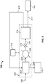
- FIG. 2 is a schematic illustration of an example of an on-board fuel separation system 200 departing from the invention as claimed.
- the system 200 may be implemented as the on-board fuel separation system 108 in the vehicle 102 shown in FIG. 1 .
- the illustrated on-board fuel separation system 200 includes an on-board fuel separation sub-assembly 202 (designated by the dashed line) that includes several components.
- the fuel stream 106 may be received at a heat exchanger 204 (for example, a plate and frame heat exchanger, shell and tube heat exchanger, fin and tube heat exchanger, or otherwise).
- the heat exchanger 204 also receives an input of a vapor fuel stream 216 that is output from the on-board fuel separation sub-assembly 202 and circulated back to the heat exchanger 204.
- the heat exchanger 204 outputs a heated fuel stream 206 to a secondary heater 208 (for example, hot coolant, hot exhaust gas, electric heater or otherwise).
- An orifice 210 (for example, valve, fixed orifice, variable orifice, or otherwise) is fluidly coupled between the heater 208 and a fuel separator 214.
- a fuel stream input 212 from the orifice 210 provides the heated fuel stream 206 (for example, at increased or decreased pressure) to the fuel separator 214.
- the fuel separator 214 may be operated at a vacuum.
- the fuel separator 214 may be operated under a vacuum (for example, lower than ambient operating pressure) to recover increased high volatility components of the fuel stream input 212.
- the fuel separator 214 in the illustrated implementation of system 200, separates the fuel stream input 212 into two fuel fraction streams: the vapor fuel stream 216 and a liquid fuel stream 217.
- the liquid fuel stream 217 may be supplied to the fractional fuel tank 114.
- the illustrated fuel separator 214 may be a flash distillation assembly that separates the input fuel stream 212 into at least two separate fuel fractions (for example, vapor stream 216 and liquid stream 217) based on a relative volatility of the fractional components of the input fuel stream.
- the flash distillation assembly may include one or more flash tanks that are fitted with screens or similar internal structures to prevent or reduce liquid droplets (mist) from being carried with the vapor stream 216.
- the flash distillation assembly may be a compact distillation unit filled with structured or random packing, or with trays, to improve the separation and prevent or reduce mist carryover into the vapor stream 216.
- a number of flash tanks in the flash distillation assembly may be determined by, for example, components of the fuel stream 106 (for example, linear alkanes, branched alkanes, cyclic alkanes, alkenes, aromatics) and their relative volatility, the volatility of additives of the fuel stream 106 such as oxygenates, desired auto-ignition characteristic value of the vapor stream 216 and the liquid stream 217, relative flow rates of the vapor stream 216 and the liquid stream 217, or a combination thereof.
- two output streams for example, the vapor stream 216 and the liquid stream 217) are shown from the fuel separator 214, more than two output streams (for example, based on a number of fuel separation stages, flash tanks, or otherwise).
- the illustrated system 200 also includes a control system 218 that is communicably coupled to the on-board fuel separation sub-assembly 202 (for example, communicably coupled to control one or more of the components, as well as unillustrated components, of the on-board fuel separation sub-assembly 202).
- the control system 218 may be a mechanical, pneumatic, electro-mechanical, or micro-processor based control system (or a combination thereof).
- the control system 218 may receive (or store) inputs associated with engine operating characteristics of an engine of a vehicle that includes the on-board fuel separation system 200 and, based on the received (or stored) inputs, send control signals to, for example, one or more valves that adjust or control the temperature, the flow rates of the fuel stream 106, the heated fuel stream 206, the vapor stream 216, the liquid stream 217, or a combination thereof.
- the control system 218 may also be communicably coupled to the fuel separator 214 to control, for example, operating temperature, pressure, or pressures, of the flash tank(s) in the fuel separator 214.
- the control system 218 may also be communicably coupled to the secondary heater 208 to, for example, further add heat to the heated fuel stream 206 prior to the fuel separator 214.
- Example engine operating characteristics include, for example, engine load, torque and speed and fuel specifications such as vapor-liquid ratio, a vapor lock index, a drivability index, a T90 or T95 property, a fuel lubricity, a fuel viscosity, or an engine speed-torque ratio, among other examples.
- Such characteristics may be used, at least in part, to adjust one or more operating characteristics of the on-board fuel separation system 202. For example, operating pressure, temperature, or both of the heat exchanger 204, the fuel separator 214, or both, may be adjusted.
- Flow rates, pressures, temperature, or a combination thereof, of one or more of the illustrated fuel streams may also be adjusted (for example, by controlling valves, not shown, with the control system 218).
- the auto-ignition characteristic values of one or both of the vapor fuel stream 216 and the liquid fuel stream 217 may be adjusted, for example, to desired values according to engine operating conditions.
- gasoline engines require high octane (for example, long ignition delay) fuel to avoid knocking and engine damage.
- the octane of the liquid stream 217 may be high octane, and the flow rate may be determined by a temperature of the fuel separator 214 (for example, at constant pressure) as shown graphically in FIGS. 5A-5C , 6A-6C .
- the on-board controller 218 may have an estimate of the amount of the high RON fuel (and associated RON value) based on a factory setting, driving history, or both.
- the controller 218 may have predictive functions that give the RON and flow values at each temperature of the fuel separator 214, and the fuel specifications (for example, vapor lock index, T95, and other specifications). The controller 218 may then set the fuel separator 214 temperature to an optimum value to maximize the amount of the high RON fuel (liquid stream 217) by allowing more or less heat in the heater 208, as needed. For other applications, the temperature could be chosen to maximize the RON value at a fixed high RON stream. Another function of the controller 218 may be to keep a minimum level of liquid in the fuel separator 214 to avoid some vapor going to the liquid tank 114. This could be accomplished by having a control valve in the conduit for the liquid stream 217.
- the octane numbers and the flow rates of the vapor stream 216 and liquid stream 217 may be determined by more than one variable: the temperatures of a reboiler and a condenser (for example, for the vapor stream 216) and a number of equilibrium stages, reflux ratio and an amount of condensate drawn from the condenser (at a fixed pressure).
- This control strategy may be similar to that described above, but with more variables to control, and there is no liquid holdup in the fuel separator 214.
- a vehicle with the on-board fuel separation system 200 may include two smaller tanks, 114 and 116, (in addition to a main fuel tank) for the two separated fuel streams 216 and 217.
- the illustrated vapor stream 216 and liquid stream 217 may have different auto-ignition characteristic values.
- the vapor stream 216 may have an auto-ignition characteristic value that is less than an auto-ignition characteristic value of the liquid stream 217.
- the auto-ignition characteristic values of the vapor stream 216 and the liquid stream 217 may be RON or cetane number.
- the fuel stream 106 is circulated (for example, forcibly pumped, sprayed, or otherwise) to the heat exchanger 204, as well as the vapor stream 216 output from the fuel separator 214. Heat from the vapor stream 216 is transferred, in the heat exchanger 204, to the fuel stream 106 and output from the heat exchanger 204 as the heated fuel stream 206.
- the vapor stream 216 which has a particular auto-ignition characteristic value (for example, a low RON relative to the RON of the liquid stream 217), condenses in the heat exchanger 204 as heat is transferred to the fuel stream 106.
- the condensed vapor stream 219 (now as a liquid stream with the low RON) may be circulated to the fractional fuel tank 116 and stored for use as a fuel source for an engine (for example, engine 124).
- the fuel stream 106 may be preheated, for example, with electric heating, heating tape, or otherwise.
- the fuel stream 106 may be preheated based on an inability of the vapor stream 216, or the heating stream through heater 208, to provide sufficient heat, in the cold start situation, to the fuel stream 106.
- one or more of the fuel fractions (for example, the low RON, condensed vapor phase 219 or the high RON liquid phase 217) stored in the fractional fuel tanks 116 and 114 may be used as the cold start fuel for the engine.
- the vapor stream 216 may not completely condense to a liquid in the heat exchanger 204.
- the partially condensed vapor stream 219 may be further cooled to more completely condense any remaining vapor in the stream 219.
- the vapor in the partially condensed vapor stream 219 may be separated and circulated to the engine with an air intake to the engine.
- a secondary heat exchanger such as a cooling coil, radiator, or otherwise, may further cool the vapor stream 219 (for example, with a cold refrigerant that is part of the vehicle air-conditioning system) between the heat exchanger 204 and the fractional fuel tank 116.
- a pressure of the partially condensed vapor stream 219 may be increased to further or fully condense the stream 219 prior to the fractional fuel tank 116.
- the heated fuel stream 206 is circulated through the secondary heater 208, which may add additional heat to the heated fuel stream 206.
- the secondary heater 208 may be controlled (for example, by the control system 218) to add additional heat so that particular auto-ignition characteristic values (for example, RON or cetane number) may be met in the vapor stream 216 and the liquid stream 217.
- the heated fuel stream 206 (further heated by the secondary heater 208 or otherwise) is circulated through the orifice 210 and into the fuel separator 214 as the fuel stream input 212.
- the orifice 210 may be controlled (for example, by the control system 218) to adjust a pressure of the fuel input stream 212 so that particular auto-ignition characteristic values (for example, RON or cetane number) may be met in the vapor stream 216 and the liquid stream 217.
- the fuel input stream 212 is circulated through the fuel separator 214 and separated (for example, based on relative volatilities of the fractions of the fuel input stream 212) into the illustrated vapor stream 216 and the illustrated liquid stream 217.
- the fuel separator 214 may separate the fuel input stream 212 into multiple vapor streams and multiple liquid streams, each with a particular auto-ignition characteristic value (for example, RON or cetane number).
- the fuel separator 214 (for example, flash tanks or distillation units or combination thereof) may have multiple separation stages.
- the liquid stream 217 output from the fuel separator 214 has an auto-ignition characteristic value (for example, RON) that is higher than the auto-ignition characteristic value of the vapor stream 216.
- the liquid stream 217 is circulated to the fractional fuel tank 114 and stored for use as a fuel source for an engine (for example, engine 124).
- FIG. 3 is a schematic illustration of another example of an on-board fuel separation system 300 departing from the invention as claimed.
- the system 300 may be implemented as the on-board fuel separation system 108 in the vehicle 102 shown in FIG. 1 .
- System 300 may be similar to system 200, shown in FIG. 2 , but also includes a power generator 318 that is fluidly coupled between a fuel separator 314 and a heat exchanger 304 within the on-board fuel separation sub-assembly 302.
- the power generator 318 may generate power (for example, electrical power), P, within a vehicle (for example, vehicle 102) that includes the on-board fuel separation system 300.
- the illustrated on-board fuel separation system 300 includes an on-board fuel separation sub-assembly 302 (designated by the dashed line) that includes several components.
- the fuel stream 106 may be received at a heat exchanger 304 (for example, a plate and frame heat exchanger, shell and tube heat exchanger, fin and tube heat exchanger, or otherwise).
- the heat exchanger 304 also receives an input of a vapor fuel stream 316 that is output from the on-board fuel separation sub-assembly 302 and circulated back to the heat exchanger 304.
- the heat exchanger 304 outputs a heated fuel stream 306 to a secondary heater 308 (for example, hot coolant, hot exhaust gas, electric heater or otherwise).
- An orifice 310 (for example, valve, fixed orifice, variable orifice, or otherwise) is fluidly coupled between the heater 308 and a fuel separator 314.
- a fuel stream input 312 from the orifice 310 provides the heated fuel stream 306 (for example, at increased or decreased pressure) to the fuel separator 314.
- the fuel separator 31 in the illustrated implementation of system 300, separates the fuel stream input 312 into two fuel fraction streams: the vapor fuel stream 316 and a liquid fuel stream 317.
- the liquid fuel stream 317 may be supplied to the fractional fuel tank 114.
- the fuel separator 314 may be operated at a vacuum.
- the fuel separator 314 may be operated under a vacuum (for example, lower than ambient operating pressure) to recover increased high volatility components of the fuel stream input 312.
- the fuel separator 314 may be operated at higher pressures (for example, pressures above ambient pressure) by regulating a pressure, a temperature, or both, of the separator 314 (for example, with a back pressure regulator downstream of the separator 314).
- the pressurized vapor stream 316 may drive the power generator 318. Power from the power generator 318 may be used, for example, as turbocharging, supercharging, electricity, or a combination thereof.
- the illustrated fuel separator 314 may be a flash distillation assembly that separates the input fuel stream 312 into at least two separate fuel fractions (for example, vapor stream 316 and liquid stream 317) based on a relative volatility of the fractional components of the input fuel stream.
- the flash distillation assembly may include one or more flash tanks that are fitted with screens or similar internal structures to prevent or reduce liquid droplets (mist) from being carried with the vapor stream 316.
- the flash distillation assembly may be a compact distillation unit filled with structured or random packing, or with trays, to improve the separation and prevent or reduce mist carryover into the vapor stream 316.
- a number of flash tanks in the flash distillation assembly may be determined by, for example, components of the fuel stream 106 (for example, linear alkanes, branched alkanes, cyclic alkanes, alkenes, aromatics) and their relative volatility, the volatility of additives of the fuel stream 106 such as oxygenates, desired auto-ignition characteristic value of the vapor stream 316 and the liquid stream 317, relative flow rates of the vapor stream 316 and the liquid stream 317, or a combination thereof.
- two output streams for example, the vapor stream 316 and the liquid stream 317) are shown from the fuel separator 314, more than two output streams (for example, based on a number of fuel separation stages, flash tanks, or otherwise).
- the power generator 318 is fluidly coupled within the vapor stream 316 between the fuel separator 314 and the heat exchanger 304.
- the power generator 318 may be a turbine or micro-turbine mounted in the vehicle that receives the vapor stream 316 at a particular pressure, which turns the turbine to generate power, P, and outputs the vapor stream 316 at a reduced pressure to the heat exchanger 304.
- the auto-ignition characteristic value for example, RON or cetane number
- the auto-ignition characteristic value of the vapor stream 316 may remain unchanged or substantially unchanged as the vapor stream 316 rotates the power generator and loses pressure.
- the illustrated system 300 also includes a control system 322 that is communicably coupled to the on-board fuel separation sub-assembly 302 (for example, communicably coupled to control one or more of the components, as well as unillustrated components, of the on-board fuel separation sub-assembly 302).
- the control system 322 may be a mechanical, pneumatic, electro-mechanical, or micro-processor based control system (or a combination thereof).
- the control system 322 may receive (or store) inputs associated with engine operating characteristics of an engine of a vehicle that includes the on-board fuel separation system 300 and, based on the received (or stored) inputs, send control signals to, for example, one or more valves that adjust or control the flow rates of the fuel stream 106, the heated fuel stream 306, the vapor stream 316, the liquid stream 317, or a combination thereof.
- the control system 322 may also be communicably coupled to the fuel separator 314 to control, for example, operating temperature, pressure, or pressures, of the flash tank(s) in the fuel separator 314.
- the control system 322 may also be communicably coupled to the secondary heater 308 to, for example, further add heat to the heated fuel stream 306 prior to the fuel separator 314.
- Example engine operating characteristics include, for example, engine load, torque and speed and fuel specifications such as vapor-liquid ratio, a vapor lock index, a drivability index, a T90 or T95 property, a fuel lubricity, a fuel viscosity, or an engine speed-torque ratio, among other examples.
- Such characteristics may be used, at least in part, to adjust one or more operating characteristics of the on-board fuel separation system 302. For example, operating pressure, temperature, or both of the heat exchanger 304, the fuel separator 324, or both, may be adjusted.
- Flow rates, pressures, temperature, or a combination thereof, of one or more of the illustrated fuel streams may also be adjusted (for example, by controlling valves, not shown, with the control system 322).
- the auto-ignition characteristic values of one or both of the vapor fuel stream 316 and the liquid fuel stream 317 may be adjusted, for example, to desired values according to engine operating conditions.
- the illustrated vapor stream 316 and liquid stream 317 may have different auto-ignition characteristic values.
- the vapor stream 316 may have an auto-ignition characteristic value that is less than an auto-ignition characteristic value of the liquid stream 317.
- the auto-ignition characteristic values of the vapor stream 316 and the liquid stream 317 may be RON or cetane number.
- the fuel stream 106 is circulated (for example, forcibly pumped, sprayed, or otherwise) to the heat exchanger 304, as well as the vapor stream 316 output from the fuel separator 314. Heat from the vapor stream 316 is transferred, in the heat exchanger 304, to the fuel stream 106 and output from the heat exchanger 304 as the heated fuel stream 306.
- the vapor stream 316 which has a particular auto-ignition characteristic value (for example, a low RON relative to the RON of the liquid stream 317), condenses in the heat exchanger 304 as heat is transferred to the fuel stream 106.
- the condensed vapor stream 319 (now as a liquid stream with the low RON) may be circulated to the fractional fuel tank 116 and stored for use as a fuel source for an engine (for example, engine 134).
- the fuel stream 106 may be preheated, for example, with electric heating, heating tape, or otherwise.
- the fuel stream 106 may be preheated based on an inability of the vapor stream 316 to provide sufficient heat, in the cold start situation, to the fuel stream 106.
- one or more of the fuel fractions (for example, the low RON, condensed vapor phase 319 or the high RON liquid phase 317) stored in the fractional fuel tanks 116 and 114 may be used as the cold start fuel for the engine.
- the vapor stream 316 may not completely condense to a liquid in the heat exchanger 304.
- the partially condensed vapor stream 319 may be further cooled to more completely condense any remaining vapor in the stream 319.
- the vapor in the partially condensed vapor stream 319 may be separated and circulated to the engine with an air intake to the engine.
- a secondary heat exchanger such as a cooling coil, radiator, or otherwise, may further cool the vapor stream 319 (for example, with a cold refrigerant that is part of the vehicle air-conditioning system) between the heat exchanger 304 and the fractional fuel tank 116.
- a pressure of the partially condensed vapor stream 319 may be increased to further or fully condense the stream 319 prior to the fractional fuel tank 116.
- the heated fuel stream 306 is circulated through the secondary heater 308, which may or may not add additional heat to the heated fuel stream 306.
- the secondary heater 308 may be controlled (for example, by the control system 322) to add additional heat so that particular auto-ignition characteristic values (for example, RON or cetane number) may be met in the vapor stream 316 and the liquid stream 317.
- the heated fuel stream 306 (further heated by the secondary heater 308 or otherwise) is circulated through the orifice 310 and into the fuel separator 314 as the fuel stream input 312.
- the orifice 310 may be controlled (for example, by the control system 322) to adjust a pressure of the fuel input stream 312 so that particular auto-ignition characteristic values (for example, RON or cetane number) may be met in the vapor stream 316 and the liquid stream 317.
- the fuel input stream 312 is circulated through the fuel separator 314 and separated (for example, based on relative volatilities of the fractions of the fuel input stream 312) into the illustrated vapor stream 316 and the illustrated liquid stream 317.
- the fuel separator 314 may separate the fuel input stream 312 into multiple vapor streams and multiple liquid streams, each with a particular auto-ignition characteristic value (for example, RON or cetane number).
- the fuel separator 314 (for example, flash tanks or distillation units or combination thereof) may have multiple separation stages.
- the vapor phase 316 is circulated to the power generator 318 (for example, a turbine or micro-turbine).
- the vapor phase 316 drives the power generator 318 to generate power, P, and is output from the power generator 318 at a lower pressure (but still in vapor phase) than that at which the phase 316 entered the generator 318.
- the lower pressure vapor phase 316 is circulated from the power generator 318 to the heat exchanger 304.
- the liquid stream 317 output from the fuel separator 314, in this example, has an auto-ignition characteristic value (for example, RON) that is higher than the auto-ignition characteristic value of the vapor stream 316.
- the liquid stream 317 is circulated to the fractional fuel tank 114 and stored for use as a fuel source for an engine (for example, engine 124).
- FIG. 4 is a schematic illustration of an embodiment of an on-board fuel separation system 400 according to the present invention.
- the system 400 may be implemented as the on-board fuel separation system 108 in the vehicle 102 shown in FIG. 1 .
- System 400 includes a power generator 424, a two stage heat exchanger system, and a two stage fuel separator system.
- the system 400 further separates the vapor stream, obtained from the first flash tank, to high RON oxygenates and low RON compounds.
- the illustrated on-board fuel separation system 400 includes an on-board fuel separation sub-assembly 402 (designated by the dashed line) that includes several components.
- the fuel stream 106 is received at a first-stage heat exchanger 404 (for example, a plate and frame heat exchanger, shell and tube heat exchanger, fin and tube heat exchanger, or otherwise).
- the first-stage heat exchanger 404 also receives an input of a vapor fuel stream 428 a low RON compounds vapor stream) that is output from the on-board fuel separation sub-assembly 402 and circulated back to the first-stage heat exchanger 404.
- the first-stage heat exchanger 404 outputs a heated fuel stream 406 to a second-stage heat exchanger 408 (for example, a plate and frame heat exchanger, shell and tube heat exchanger, fin and tube heat exchanger, or otherwise).
- the second-stage heat exchanger 408 receives the heated fuel stream 406 and a combined liquid fuel stream that includes a high RON liquid stream 430 output from a first stage fuel separator 418 and a high RON oxygenate fuel stream 432 from a second-stage fuel separator 422. These two fuel streams combine and are circulated to the second-stage heat exchanger 408 to provide further heat to the heated fuel stream 406 prior to fuel separation.
- a combined high RON fuel stream 417 is circulated to the fractional fuel tank 114 (for example, a high RON fuel tank).
- the fractional fuel tank 114 for example, a high RON fuel tank.
- one or both of the high RON liquid stream 430 and the high RON oxygenate fuel stream 432 may be supplied to the fractional fuel tank 114 without passing through the second-stage heat exchanger 408.
- a first-stage heat exchanger 404 thus receives the fuel stream 106 and a combined liquid fuel stream that includes a high RON liquid stream 430 output from a first stage fuel separator 418 and a high RON oxygenate fuel stream 432 from a second-stage fuel separator 422.
- the first-stage heat exchanger 404 outputs the heated fuel stream 406 to the second-stage heat exchanger 408, which receives an input of a vapor fuel stream 428 ( a low RON compounds vapor stream) that is output from the on-board fuel separation sub-assembly 402.
- the further heated fuel stream 410 is fluidly coupled to a secondary heater 412 (for example, hot coolant, hot exhaust gas, electric heater or otherwise) that can controllably provide additional heat to the fuel stream 410.
- An orifice 414 (for example, valve, fixed orifice, variable orifice, or otherwise) is fluidly coupled between the heater 412 and a first-stage fuel separator 418.
- a fuel stream input 416 from the orifice 414 provides the further heated fuel stream 410 (for example, at increased or decreased pressure) to the first-stage fuel separator 418.
- the first-stage fuel separator 414 in the illustrated embodiment of system 400, separates the fuel stream input 416 into two fuel fraction streams: a low RON vapor fuel stream 420 and a high RON liquid fuel stream 430 based on a volatility of the fuel stream input 416.
- the high RON liquid fuel stream 430 may be supplied to the fractional fuel tank 114 as described previously.
- the separated low RON vapor fuel stream 420 is fluidly coupled to a second-stage fuel separator 422.
- the second-stage fuel separator 422 separates ( based on volatility of the vapor stream 420) the vapor stream 420 into a low RON compound stream 428 and a high RON oxygenate stream 432.
- the high RON oxygenate stream 432 combines with the high RON liquid stream (for example, through the second-stage heat exchanger 408 or the fractional fuel tank 114).
- each flash distillation assembly may include one or more flash tanks that are fitted with screens or similar internal structures to prevent or reduce liquid droplets (mist) from being carried with a vapor stream within the fuel separator.
- each flash distillation assembly may be a compact distillation unit filled with structured or random packing, or with trays, to improve the separation and prevent or reduce mist carryover into a vapor stream.
- a number of flash tanks in each flash distillation assembly may be determined by, for example, components of the fuel stream 106 (for example, linear alkanes, branched alkanes, cyclic alkanes, alkenes, aromatics) and their relative volatility, the volatility of additives of the fuel stream 106 such as oxygenates, desired auto-ignition characteristic value of a resultant low RON stream or high RON stream, relative flow rates of the resultant low RON stream or high RON stream, or a combination thereof.
- components of the fuel stream 106 for example, linear alkanes, branched alkanes, cyclic alkanes, alkenes, aromatics
- the volatility of additives of the fuel stream 106 such as oxygenates, desired auto-ignition characteristic value of a resultant low RON stream or high RON stream, relative flow rates of the resultant low RON stream or high RON stream, or a combination thereof.
- first-stage fuel separator 418 and second-stage fuel separator 422 may be operated at a vacuum.
- first-stage fuel separator 414, the second-stage fuel separator 422, or both may be operated under a vacuum (for example, lower than ambient operating pressure) to recover increased high volatility components of the fuel stream input 416 or low RON vapor stream 420.
- a power generator 424 is fluidly coupled within the low RON compounds (vapor) stream 428 between the second-stage fuel separator 422 and the first-stage heat exchanger 404.
- the power generator 424 may be a turbine or micro-turbine mounted in the vehicle that receives the low RON compounds (vapor) stream 428 at a particular pressure, which turns the turbine to generate power, P, and outputs the low RON compounds (vapor) stream 428 at a reduced pressure to the first-stage heat exchanger 404.
- the auto-ignition characteristic value (RON according to the invention, cetane number departing herefrom) of the low RON compounds (vapor) stream 428 may remain unchanged or substantially unchanged as the low RON compounds (vapor) stream 428 rotates the power generator 424 and loses pressure.
- the illustrated system 400 also includes a control system 426 that is communicably coupled to the on-board fuel separation sub-assembly 402 (for example, communicably coupled to control one or more of the components, as well as unillustrated components, of the on-board fuel separation sub-assembly 402).
- the control system 426 may be a mechanical, pneumatic, electro-mechanical, or micro-processor based control system (or a combination thereof).
- the control system 426 may receive (or store) inputs associated with engine operating characteristics of an engine of a vehicle that includes the on-board fuel separation system 400 and, based on the received (or stored) inputs, send control signals to, for example, one or more valves that adjust or control the flow rates of the fuel stream 106, the heated fuel streams 406, 410, and/or 416, the low RON vapor stream 420, the high RON liquid stream 430, the low RON compounds stream 428, the high RON oxygenate stream 432, or a combination thereof.
- the control system 426 may also be communicably coupled to the first-stage fuel separator 418, the second-stage fuel separator 422, or both, to control, for example, operating pressure, or pressures, of the flash tank(s) in the fuel separators 418 and 422.
- the control system 426 may also be communicably coupled to the secondary heater 412 to, for example, further add heat to the heated fuel stream 410 prior to the first-stage fuel separator 418.
- Example engine operating characteristics include, for example, engine load, torque and speed and fuel specifications such as vapor-liquid ratio, a vapor lock index, a drivability index, a T90 or T95 property, a fuel lubricity, a fuel viscosity, or an engine speed-torque ratio, among other examples.
- Such characteristics may be used, at least in part, to adjust one or more operating characteristics of the on-board fuel separation system 402. For example, operating pressure, temperature, or both of the first or second stage heat exchangers 404/408, the first or second stage fuel separators 418/422, or combinations thereof, may be adjusted.
- Flow rates, pressures, temperature, or a combination thereof, of one or more of the illustrated fuel streams may also be adjusted (for example, by controlling valves, not shown, with the control system 426).
- the auto-ignition characteristic values of one or both of the vapor fuel stream 420 and the liquid fuel stream 430 may be adjusted, for example, to desired values according to engine operating conditions.
- the fuel stream 106 and the low RON compounds vapor stream 428 are circulated (for example, forcibly pumped, sprayed, or otherwise) to the first-stage heat exchanger 404. Heat from the vapor stream 428 is transferred, in the first-stage heat exchanger 404, to the fuel stream 106 and output from the first-stage heat exchanger 404 as the heated fuel stream 406.
- the vapor stream 428 which has a low RON relative to the RON of the liquid stream 430, condenses in the first-stage heat exchanger 404 as heat is transferred to the fuel stream 106.
- the condensed vapor stream 419 (now as a liquid stream with the low RON) may be circulated to the fractional fuel tank 116 and stored for use as a fuel source for an engine (for example, engine 124).
- the fuel stream 106 may be preheated, for example, with electric heating, heating tape, or otherwise.
- the fuel stream 106 may be preheated based on an inability of the vapor stream 418 to provide sufficient heat, in the cold start situation, to the fuel stream 106.
- one or more of the fuel fractions (for example, the low RON, condensed vapor phase 419 or the combined high RON liquid phase 417) stored in the fractional fuel tanks 116 and 114 may be used as the cold start fuel for the engine.
- the low RON compounds vapor stream 428 may not completely condense to a liquid in the first-stage heat exchanger 404.
- the partially condensed vapor stream 419 may then be further cooled to more completely condense any remaining vapor in the stream 419.
- the vapor in the partially condensed vapor stream 419 may be separated and circulated to the engine with an air intake to the engine.
- a secondary heat exchanger such as a cooling coil, radiator, or otherwise, may further cool the vapor stream 419 (for example, with a cold refrigerant that is part of the vehicle air-conditioning system) between the first-stage heat exchanger 404 and the fractional fuel tank 116.
- a pressure of the partially condensed vapor stream 419 may be increased to further or fully condense the stream 419 prior to the fractional fuel tank 116.
- the heated fuel stream 406 is circulated through the second-stage heat exchanger 408, which also receives the combined high RON liquid stream 430 and high RON oxygenate stream 432 . Heat is transferred, in the second-stage heat exchanger 408, from the combined high RON streams to the heated fuel stream 406.
- the further heated fuel stream 410 is circulated from the second-stage heat exchanger 408 to the secondary heater 412, which may or may not add additional heat to the heated fuel stream 410.
- the secondary heater 412 may be controlled (for example, by the control system 426) to add additional heat so that particular RON levels may be met in the vapor stream 420 and the liquid stream 430.
- the further heated fuel stream 410 (further heated by the secondary heater 412 or otherwise) is circulated through the orifice 414 and into the first-stage fuel separator 418 as the fuel stream input 416.
- the orifice 414 may be controlled (for example, by the control system 426) to adjust a pressure of the fuel input stream 412 so that particular RON levels may be met in the vapor stream 416 and the liquid stream 417.
- the fuel input stream 416 is circulated through the first-stage fuel separator 418 and separated ( based on relative volatilities of the fractions of the fuel input stream 416) into the illustrated low RON vapor stream 420 and the illustrated high RON liquid stream 430.
- the liquid stream 430 output from the first-stage fuel separator 418 a RON that is higher than the auto-ignition characteristic value of the vapor stream 420.
- the liquid stream 430 is circulated through the second-stage heat exchanger 408 (along with high RON oxygenate stream 432) to the fractional fuel tank 114 and stored for use as a fuel source for an engine (for example, engine 124).
- the illustrated low RON vapor stream 420 is circulated from the first-stage fuel separator 418 to the second-stage fuel separator 422.
- the low RON vapor stream 420 is separated ( based on relative volatilities of the fractions of the vapor stream 420) into the low RON compounds vapor stream 428 and the high RON oxygenate stream 432.
- the low RON compounds vapor stream 428 is then circulated to the power generator 424 to drive the generator and produce power.
- the low RON compounds vapor stream 428 is circulated (at a lower pressure) to the first-stage heat exchanger 404, where it is condensed to the condensed low RON fuel stream 419 for storage in the fractional fuel tank 416 as a fuel source for an engine (for example, engine 124).
- FIGS. 5A-5C are graphs 500, 505, and 510, respectively, that illustrate results of a simulation model of an on-board fuel separation system departing from he invention as claimed.
- the simulation model which results are shown in graphs 500, 505, and 510 simulates an operation of an on-board fuel separation system for a vehicle that includes a heat exchanger and single stage fuel separator, for example, as shown in system 200 in FIG. 2 .
- a fuel stream (for example, fuel stream 106) is 91 gasoline mixed with methyl tertiary butyl ether (MTBE).
- MTBE methyl tertiary butyl ether
- Graph 500 illustrates RON of a liquid fuel stream (for example, liquid stream 217) and RON of a vapor fuel stream (for example, vapor fuel stream 216) relative to an operating temperature of a fuel separator (for example, fuel separator 214).
- the fuel separator of the simulation model is a single flash tank distillation unit.
- a relative difference in RON between the liquid fuel stream and the vapor fuel stream generally increases as flash distillation increases (up to 26 in RON difference).
- Graph 505 illustrates RON of the liquid fuel stream and RON of the vapor fuel stream relative to an operating volumetric flow rate of the condensed vapor fuel stream (for example, fuel stream 219) of the fuel separator.
- a relative difference in RON between the liquid fuel stream and the vapor fuel stream generally increases as volumetric flow rate of the condensed vapor fuel stream from the flash distillation unit increases (up to 26 in RON difference).
- Graph 510 illustrates heat flow rate relative to operating temperature of the fuel separator.
- the "Required Heat” line represents the required thermal energy per liter of incoming fuel in line 106 to achieve the RON differential at the specified temperature (for example, heat supplied to the fuel stream through heat exchanger(s), heaters, or both).
- the "Coolant” line represents the available thermal energy per liter of incoming fuel in the hot coolant that could be used in heat exchanger 208. In some aspects, beyond about 80°C, this heat is not usable (in heat exchanger 208) as the temperature difference may be zero or negative.
- the "Exhaust” line represents the available thermal energy per liter of incoming fuel in the exhaust gas that could be used in heat exchanger 208.
- FIGS. 6A-6C are graphs 600, 605, and 610, respectively, that illustrate results of another simulation model of an on-board fuel separation system departing from the invention as claimed.
- the simulation model which results are shown in graphs 600, 605, and 610 simulates an operation of an on-board fuel separation system for a vehicle that includes a heat exchanger and single stage fuel separator, for example, as shown in system 200 in FIG. 2 .
- a fuel stream (for example, fuel stream 106) is 91 gasoline without oxygenates.
- Graph 600 illustrates RON of a liquid fuel stream (for example, liquid stream 217) and RON of a vapor fuel stream (for example, vapor fuel stream 216) relative to an operating temperature of a fuel separator (for example, fuel separator 214).
- the fuel separator of the simulation model is a single tank flash distillation unit.
- a relative difference in RON between the liquid fuel stream and the vapor fuel stream generally increases as flash distillation increases (up to 29 in RON difference).
- Graph 605 illustrates RON of the liquid fuel stream and RON of the vapor fuel stream relative to an operating volumetric flow rate of the vapor fuel stream (for example, fuel stream 219) of the fuel separator.
- a relative difference in RON between the liquid fuel stream and the vapor fuel stream generally increases as volumetric flow rate of the condensed vapor fuel stream from the flash distillation unit increases (up to 29 in RON difference).
- Graph 610 illustrates heat flow rate relative to operating temperature of the fuel separator.
- the "Required Heat” line represents the required thermal energy per liter of incoming fuel in line 106 to achieve the RON differential at the specified temperature (for example, heat supplied to the fuel stream through heat exchanger(s), heaters, or both).
- the "Coolant” line represents the available thermal energy per liter of incoming fuel in the hot coolant that could be used in heat exchanger 208. In some aspects, beyond about 80°C, this heat is not usable (in heat exchanger 208) as the temperature difference may be zero or negative.
- the "Exhaust” line represents the available thermal energy per liter of incoming fuel in the exhaust gas that could be used in heat exchanger 208.
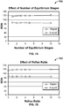
- FIGS. 7A and 7B are graphs 700 and 705, respectively, that illustrate results of another simulation model of an on-board fuel separation system.
- Graph 700 shows an effect of a number of equilibrium stages in a fuel separator (for example, a compact distillation unit or a fuel separator with multiple flash tanks) on an auto-ignition characteristic value; here, RON.
- Graph 705 shows an effect of a reflux ratio on an auto-ignition characteristic value; here, RON.
- the number of equilibrium stages and the reflux ratio are additional design variables, which can be varied to vary RON of the output streams (for example, vapor and liquid streams).
- FIG. 8 is a schematic illustration of an example controller 800 (or control system) for an on-board fuel separation system according to he embodiment and examples departing from the invention as claimed.
- the controller 800 can be used for the operations described previously, for example as or as part of the control systems 218, 322, 426 or other controllers described herein.
- the controller 800 may be communicably coupled with, or as a part of, one or both of a vehicle engine and on-board fuel separation system as described herein.
- the controller 800 is intended to include various forms of digital computers, such as printed circuit boards (PCB), processors, digital circuitry, or otherwise that is part of a vehicle. Additionally the system can include portable storage media, such as, Universal Serial Bus (USB) flash drives. For example, the USB flash drives may store operating systems and other applications. The USB flash drives can include input/output components, such as a wireless transmitter or USB connector that may be inserted into a USB port of another computing device.
- PCB printed circuit boards
- USB flash drives may store operating systems and other applications.
- USB flash drives can include input/output components, such as a wireless transmitter or USB connector that may be inserted into a USB port of another computing device.
- the controller 800 includes a processor 810, a memory 820, a storage device 830, and an input/output device 840. Each of the components 810, 820, 830, and 840 are interconnected using a system bus 850.
- the processor 810 is capable of processing instructions for execution within the controller 800.
- the processor may be designed using any of a number of architectures.
- the processor 810 may be a CISC (Complex Instruction Set Computers) processor, a RISC (Reduced Instruction Set Computer) processor, or a MISC (Minimal Instruction Set Computer) processor.
- the processor 810 is a single-threaded processor. In another implementation, the processor 810 is a multi-threaded processor.
- the processor 810 is capable of processing instructions stored in the memory 820 or on the storage device 830 to display graphical information for a user interface on the input/output device 840.
- the memory 820 stores information within the controller 800.
- the memory 820 is a computer-readable medium.
- the memory 820 is a volatile memory unit.
- the memory 820 is a non-volatile memory unit.
- the storage device 830 is capable of providing mass storage for the controller 800.
- the storage device 830 is a computer-readable medium.
- the storage device 830 may be a floppy disk device, a hard disk device, an optical disk device, or a tape device.
- the input/output device 840 provides input/output operations for the controller 800.
- the input/output device 840 includes a keyboard and/or pointing device.
- the input/output device 840 includes a display unit for displaying graphical user interfaces.
Landscapes
- Engineering & Computer Science (AREA)
- Chemical & Material Sciences (AREA)
- Mechanical Engineering (AREA)
- Combustion & Propulsion (AREA)
- General Engineering & Computer Science (AREA)
- Oil, Petroleum & Natural Gas (AREA)
- Chemical Kinetics & Catalysis (AREA)
- Life Sciences & Earth Sciences (AREA)
- Sustainable Development (AREA)
- Sustainable Energy (AREA)
- Transportation (AREA)
- Combined Controls Of Internal Combustion Engines (AREA)
- Output Control And Ontrol Of Special Type Engine (AREA)
- Air-Conditioning For Vehicles (AREA)
Claims (16)
- Kraftstofftrennsystem (108, 400), umfassend:einen Kraftstofftrenner (108, 418, 422), der dazu ausgelegt ist, einen Kraftstoffstrom (106, 406, 410) zu empfangen und den Kraftstoffstrom (106, 406, 410) basierend auf einer Volatilität des Kraftstoffstroms in einen ersten Dampfstrom (428) von Verbindungen mit relativ niedriger Research-Oktanzahl und einen kombinierten Flüssigkeitsstrom von Verbindungen mit relativ hoher Research-Oktanzahl zu trennen; undeinen Wärmetauscher (404, 408), der fluidisch zwischen einem Kraftstoffeingang des Kraftstoffstroms (106, 406, 410) und dem Kraftstofftrenner gekoppelt ist, wobei der Wärmetauscher dazu ausgelegt ist, Wärme aus dem ersten Dampfstrom (428) an den Kraftstoffstrom zu übertragen und einen erwärmten Kraftstoffstrom (406, 410) an den Kraftstofftrenner und einen zweiten Flüssigkeitsstrom (419) von Verbindungen mit relativ niedrigerer Research-Oktanzahl auszugeben,wobei der Kraftstofftrenner (108, 418, 422) einen Kraftstofftrenner einer ersten Stufe (418) und einen Kraftstofftrenner einer zweiten Stufe (422) umfasst,wobei der Kraftstofftrenner (418) der ersten Stufe dazu ausgelegt ist, den erwärmten Kraftstoffstrom (406, 410) zu empfangen und den erwärmten Kraftstoffstrom (406, 410) basierend auf der Volatilität des erwärmten Kraftstoffstroms (406, 410) in einen zweiten Dampfstrom (420) von Verbindungen mit relativ niedrigerer Research-Oktanzahl und einen dritten Flüssigkeitsstrom (430) von Verbindungen mit relativ hoher Research-Oktanzahl zu trennen, undwobei der Kraftstofftrenner (422) der zweiten Stufe dazu ausgelegt ist, den durch den Kraftstofftrenner (418) der ersten Stufe getrennten zweiten Dampfstrom (420) in einen Oxygenatstrom (432) und den ersten Dampfstrom (428) zu trennen, aus dem Wärme durch den Wärmetauscher (404, 408) an den Kraftstoffstrom (106, 406, 410) übertragen wird,wobei der kombinierte Flüssigkeitsstrom den dritten Flüssigkeitsstrom (430) aus dem Kraftstofftrenner der ersten Stufe (418) und den Oxygenatstrom (432) aus dem Kraftstofftrenner der zweiten Stufe (422) enthält.
- Kraftstofftrennsystem gemäß Anspruch 1, wobei der Kraftstofftrenner (108, 418, 422) einen Entspannungsdestillationstrenner umfasst.
- Kraftstofftrennsystem gemäß Anspruch 1, ferner umfassend eine Heizvorrichtung (412), die zwischen dem Wärmetauscher (404, 408) und dem Kraftstofftrenner (108, 418, 422) gekoppelt und dazu ausgelegt ist, den erwärmten Kraftstoffstrom (406, 410) zu empfangen und den erwärmten Kraftstoffstrom (406, 410) weiter zu erwärmen.
- Kraftstofftrennsystem gemäß Anspruch 1, ferner umfassend eine variable Blende (414), die fluidisch zwischen dem Wärmetauscher (404, 408) und dem Kraftstofftrenner (108, 418, 422) gekoppelt ist.
- Kraftstofftrennsystem gemäß Anspruch 4, ferner umfassend eine Steuervorrichtung (426), die betriebsmäßig dazu gekoppelt ist, mindestens eines des Kraftstofftrenners (108, 418, 422) oder der variablen Blende (414) zu steuern, um einen Volumenstrom von mindestens einem des erwärmten Kraftstoffstroms (406, 410), des ersten Dampfstroms (428) oder des kombinierten Flüssigkeitsstroms zu verändern.
- Kraftstofftrennsystem gemäß Anspruch 5, wobei die Steuervorrichtung (426) dazu ausgelegt ist, die Research-Oktanzahlwerte von mindestens einem oder beiden des zweiten Kraftstoffdampfstroms (420) und des dritten Flüssigkraftstoffstroms (430) basierend mindestens teilweise auf mindestens einem Motorbetriebszustand, wobei der mindestens eine Motorbetriebszustand beispielsweise eine Motorlast, ein Motordrehmoment und eine Motordrehzahl, ein Kraftstoffdampf-Flüssigkeits-Verhältnis, einen Kraftstoffdampfsperrindex, einen Kraftstofffahrbarkeitsindex, eine Kraftstoff-T90- oder - T95-Eigenschaft, eine Kraftstoffschmierfähigkeit, eine Kraftstoffviskosität oder ein Motordrehzahl-Drehmoment-Verhältnis umfasst, zu verändern.
- Kraftstofftrennsystem gemäß Anspruch 1, wobei der Kraftstofftrenner (422) der zweiten Stufe dazu ausgelegt ist, den Oxygenatstrom (432) so zu leiten, dass er sich mit dem aus dem Kraftstofftrenner (418) der ersten Stufe austretenden dritten Flüssigkeitsstrom (430) kombiniert, und den kombinierten Flüssigkeitsstrom an den Wärmetauscher (404, 408) zu leiten.
- Fahrzeugsystem (100), umfassend
ein Fahrzeug (102);
einen im Fahrzeug eingebauten kraftstoffbetriebenen Verbrennungsmotor (124);
ein bordeigenes Kraftstofftrennsystem, umfassend das Kraftstofftrennsystem gemäß einem der vorhergehenden Ansprüche, wobei der Kraftstofftrenner (108, 418, 422) dazu ausgelegt ist, im Fahrzeug gespeicherten Kraftstoff zu empfangen und den Kraftstoff zu trennen;
einen ersten Kraftstofftank (114), der fluidisch zwischen dem Motor und dem Kraftstofftrenner (108, 418, 422) gekoppelt ist, um den aus dem Kraftstofftrenner (108, 418, 422) ausgegebenen kombinierten Flüssigkeitsstrom zu speichern; und
einen zweiten Kraftstofftank (116), der fluidisch zwischen dem Motor und dem Wärmetauscher (404, 408) gekoppelt ist, um den aus dem Wärmetauscher (404, 408) ausgegebenen zweiten Flüssigkeitsstrom (419) zu speichern. - Fahrzeugsystem gemäß Anspruch 8, ferner umfassend eine Turbine (424), die einen mit dem Kraftstofftrenner (108, 418, 422) fluidisch gekoppelten Eingang und einen mit dem Wärmetauscher (404, 408) fluidisch gekoppelten Ausgang umfasst und dazu ausgelegt ist, den ersten Dampfstrom (428) aus dem Kraftstofftrenner (108, 418, 422) zu empfangen und basierend auf einer Druckdifferenz des ersten Dampfstroms (428) zwischen dem Eingang und dem Ausgang elektrische Energie zu erzeugen.
- Verfahren zum Trennen eines Kraftstoffs an Bord eines Fahrzeugs, umfassend:Trennen eines erwärmten Kraftstoffstroms (406, 410) mit einem Kraftstofftrenner (108, 418, 422) in einen ersten Dampfstrom (428) von Verbindungen mit relativ niedrigerer Research-Oktanzahl und einen kombinierten Flüssigkeitsstrom aus Verbindungen mit relativ höherer Research-Oktanzahl basierend auf einer Volatilität des erwärmten Kraftstoffstroms (406, 410), wobei der Kraftstofftrenner (108, 418, 422) einen Kraftstofftrenner (418) der ersten Stufe und einen Kraftstofftrenner (422) der zweiten Stufe umfasst;Zuführen eines unerwärmten Kraftstoffstroms (106) und des ersten Dampfstroms (428) aus dem Kraftstofftrenner (108, 418, 422) an einen Wärmetauscher (404, 408);Übertragen von Wärme aus dem ersten Dampfstrom (428) an den unerwärmten Kraftstoffstrom (106), um den unerwärmten Kraftstoffstrom (106) zu erwärmen;Zuführen des erwärmten Kraftstoffstroms (406, 410) an den Kraftstofftrenner (108, 418, 422);Trennen des erwärmten Kraftstoffstroms (406, 410) mit dem Kraftstofftrenner (418) der ersten Stufe in einen zweiten Dampfstrom (420) von Verbindungen mit relativ niedrigerer Research-Oktanzahl und einen ersten Flüssigkeitsstrom (430) aus Verbindungen mit relativ hoher Research-Oktanzahl basierend auf der Volatilität des erwärmten Kraftstoffstroms (106, 406, 410), undTrennen des durch den Kraftstofftrenner der ersten Stufe getrennten zweiten Dampfstroms (420) mit dem Kraftstofftrenner der zweiten Stufe (422) in einen Oxygenatstrom (432) und den ersten Dampfstrom (428); undZuführen eines zweiten Flüssigkeitsstroms (419) von Verbindungen mit relativ niedrigerer Research-Oktanzahl aus dem Wärmetauscher (404, 408).
- Verfahren gemäß Anspruch 10, ferner umfassend:weiteres Erwärmen des erwärmten Kraftstoffstroms (406, 410); undZuführen des weiter erwärmten Kraftstoffstroms (406, 410) an den Kraftstofftrenner (108, 418, 422), undgegebenenfalls wobei das weitere Erwärmen des erwärmten Kraftstoffstroms (406, 410) mindestens eines umfasst vona) Erwärmen des erwärmten Kraftstoffstroms (406, 410) mit einer elektrischen Heizvorrichtung (412),b) Erwärmen des erwärmten Kraftstoffstroms (406, 410) im Wärmetauscher (404, 408) mit dem kombinierten Flüssigkeitsstrom, oderc) Erwärmen des erwärmten Kraftstoffstroms (406, 410) in einem weiteren Wärmetauscher (412) mit einem Motorabgasstrom.
- Verfahren gemäß Anspruch 10, ferner umfassend das Zirkulieren des erwärmten Kraftstoffstroms (406, 410) durch eine variable Blende (414), die fluidisch zwischen dem Wärmetauscher (404, 408) und dem Kraftstofftrenner (108, 418, 422) gekoppelt ist.
- Verfahren gemäß Anspruch 12, ferner umfassend Steuern von mindestens einem des Kraftstofftrenners (108, 418, 422) oder der variablen Blende (414), um einen Volumenstrom von mindestens einem des erwärmten Kraftstoffstroms (406, 410), des ersten Dampfstroms (428) oder des kombinierten Flüssigkeitsstroms zu verändern.
- Verfahren gemäß Anspruch 13, ferner umfassend Verändern mindestens eines von Research-Oktanzahlwerten des einen oder der beiden des zweiten Dampfkraftstoffstroms (420) und des dritten Flüssigkraftstoffstroms (430) basierend mindestens teilweise auf mindestens einem Motorbetriebszustand, wobei der mindestens eine Motorbetriebszustand beispielsweise eine Motorlast, ein Motordrehmoment, eine Motordrehzahl, ein Kraftstoffdampf-Flüssigkeits-Verhältnis, einen Kraftstoffdampfsperrindex, einen Kraftstofffahrbarkeitsindex, eine Kraftstoff-T90- oder T95-Eigenschaft, eine Kraftstoffschmierfähigkeit, eine Kraftstoffviskosität oder ein Motordrehzahl-Drehmoment-Verhältnis umfasst.
- Verfahren gemäß Anspruch 10, wobei der Kraftstofftrenner (108, 418, 422) einen Entspannungsdestillationstrenner umfasst.
- Verfahren gemäß Anspruch 10, ferner umfassend:Kombinieren des Oxygenatstroms (432) mit dem ersten Flüssigkeitsstrom (430); undZuführen des kombinierten Flüssigkeitsstroms an den Wärmetauscher (404, 408).
Applications Claiming Priority (2)
| Application Number | Priority Date | Filing Date | Title |
|---|---|---|---|
| US15/044,584 US9816467B2 (en) | 2016-02-16 | 2016-02-16 | Adjusting a fuel on-board a vehicle |
| PCT/US2017/013706 WO2017142658A1 (en) | 2016-02-16 | 2017-01-17 | Adjusting a fuel composition on-board a vehicle |
Publications (2)
| Publication Number | Publication Date |
|---|---|
| EP3417166A1 EP3417166A1 (de) | 2018-12-26 |
| EP3417166B1 true EP3417166B1 (de) | 2021-03-31 |
Family
ID=57944541
Family Applications (1)
| Application Number | Title | Priority Date | Filing Date |
|---|---|---|---|
| EP17702475.9A Active EP3417166B1 (de) | 2016-02-16 | 2017-01-17 | Einstellen einer kraftstoffzusammensetzung an bord eines fahrzeugs |
Country Status (5)
| Country | Link |
|---|---|
| US (2) | US9816467B2 (de) |
| EP (1) | EP3417166B1 (de) |
| JP (1) | JP6818759B2 (de) |
| SA (1) | SA518392216B1 (de) |
| WO (1) | WO2017142658A1 (de) |
Families Citing this family (11)
| Publication number | Priority date | Publication date | Assignee | Title |
|---|---|---|---|---|
| US10378427B2 (en) | 2017-03-31 | 2019-08-13 | Saudi Arabian Oil Company | Nitrogen enriched air supply for gasoline compression ignition combustion |
| US10508017B2 (en) * | 2017-10-13 | 2019-12-17 | Saudi Arabian Oil Company | Point-of-sale octane/cetane-on-demand systems for automotive engines |
| US10436126B2 (en) * | 2018-01-31 | 2019-10-08 | Saudi Arabian Oil Company | Adsorption-based fuel systems for onboard cetane on-demand and octane on-demand |
| US10378462B1 (en) | 2018-01-31 | 2019-08-13 | Saudi Arabian Oil Company | Heat exchanger configuration for adsorption-based onboard octane on-demand and cetane on-demand |
| US10422288B1 (en) | 2018-03-29 | 2019-09-24 | Saudi Arabian Oil Company | Adsorbent circulation for onboard octane on-demand and cetane on-demand |
| US10408139B1 (en) | 2018-03-29 | 2019-09-10 | Saudi Arabian Oil Company | Solvent-based adsorbent regeneration for onboard octane on-demand and cetane on-demand |
| US11118548B2 (en) * | 2019-02-08 | 2021-09-14 | Walbro Llc | Vapor separator with thermoelectric heat exchanger |
| JP7344019B2 (ja) * | 2019-06-24 | 2023-09-13 | 株式会社ジャパンエンジンコーポレーション | 舶用内燃機関 |
| US11339754B1 (en) | 2021-05-07 | 2022-05-24 | Saudi Arabian Oil Company | Vehicle system with fuel separation system and method of using same |
| JP7679754B2 (ja) * | 2021-10-26 | 2025-05-20 | マツダ株式会社 | 移動体の温度制御システム |
| US20250243831A1 (en) * | 2024-01-31 | 2025-07-31 | Deere & Company | Fuel delivery system and method for spark ignited engines of work vehicles |
Citations (1)
| Publication number | Priority date | Publication date | Assignee | Title |
|---|---|---|---|---|
| EP3417165A1 (de) * | 2016-02-16 | 2018-12-26 | Saudi Arabian Oil Company | Einstellung eines brennstoffs an bord eines fahrzeuges |
Family Cites Families (68)
| Publication number | Priority date | Publication date | Assignee | Title |
|---|---|---|---|---|
| DE2431016C2 (de) | 1973-07-28 | 1983-11-03 | Suzuki Jidosha Kogyo K.K., Kami, Shizuoka | Vergaser für Brennkraftmaschinen |
| US4210103A (en) * | 1977-04-04 | 1980-07-01 | Southwest Research Institute | Fuel system for and a method of operating a spark-ignited internal combustion engine |
| JPH0741882Y2 (ja) * | 1989-04-26 | 1995-09-27 | トヨタ自動車株式会社 | 蒸発燃料処理装置 |
| US5357908A (en) | 1993-04-16 | 1994-10-25 | Engelhard Corporation | Fuel modification method and apparatus for reduction of pollutants emitted from internal combustion engines |
| US5794601A (en) | 1997-05-16 | 1998-08-18 | Pantone; Paul | Fuel pretreater apparatus and method |
| GB2330176A (en) | 1997-10-09 | 1999-04-14 | Ford Global Tech Inc | Fractional distillation of fuel and variable supply of fuel fractions for an internal combustion engine |
| JP4510173B2 (ja) * | 1999-04-06 | 2010-07-21 | 日産自動車株式会社 | 燃料改質装置付き内燃機関 |
| DE60025412T2 (de) * | 1999-06-01 | 2006-08-31 | Nissan Motor Co., Ltd., Yokohama | Brennstoffzufuhrvorrichtung einer Brennkraftmaschine |
| US6119637A (en) | 1999-07-06 | 2000-09-19 | Ford Global Technologies, Inc. | On-board gasoline distillation for reduced hydrocarbon emissions at start-up |
| EP1365137B9 (de) | 2001-02-26 | 2006-07-12 | Mitsubishi Jidosha Kogyo Kabushiki Kaisha | Abgasreiniger für brennkraftmaschinen |
| US6711893B2 (en) | 2001-03-27 | 2004-03-30 | Toyota Jidosha Kabushiki Kaisha | Fuel supply apparatus for an internal combustion engine |
| US6378489B1 (en) * | 2001-05-24 | 2002-04-30 | Rudolf H. Stanglmaier | Method for controlling compression ignition combustion |
| US6494192B1 (en) | 2001-06-12 | 2002-12-17 | Southwest Research Institute | On-board fuel vapor collection, condensation, storage and distribution system for a vehicle |
| EP1371715A1 (de) | 2002-06-13 | 2003-12-17 | Shell Internationale Researchmaatschappij B.V. | Kraftstoffzusammensetzungen |
| AT414156B (de) | 2002-10-11 | 2006-09-15 | Dirk Peter Dipl Ing Claassen | Verfahren und einrichtung zur rückgewinnung von energie |
| US6972093B2 (en) * | 2003-01-30 | 2005-12-06 | Exxonmobil Research And Engineering Company | Onboard fuel separation apparatus for an automobile |
| JP2005002914A (ja) | 2003-06-12 | 2005-01-06 | Toyota Motor Corp | 火花点火式内燃機関 |
| US7107942B2 (en) * | 2003-07-08 | 2006-09-19 | Exxonmobil Research And Engineering Company | Fuel composition supply means for spark ignition engines |
| JP4244786B2 (ja) * | 2003-11-07 | 2009-03-25 | トヨタ自動車株式会社 | 車載用燃料分離装置 |
| US7435760B2 (en) | 2004-05-14 | 2008-10-14 | Battelle Memorial Institute | Method of generating hydrocarbon reagents from diesel, natural gas and other logistical fuels |
| JP4389695B2 (ja) | 2004-06-30 | 2009-12-24 | トヨタ自動車株式会社 | 内燃機関の燃料分留装置 |
| US20060037589A1 (en) * | 2004-08-17 | 2006-02-23 | Ramesh Gupta | Heat pipe for heating of gasoline for on-board octane segregation |
| US7523724B2 (en) * | 2006-09-25 | 2009-04-28 | Intelligent Energy, Inc. | In transit desulfurization of widely available fuels |
| US7754931B2 (en) | 2005-09-26 | 2010-07-13 | Her Majesty The Queen In Right Of Canada As Represented By The Minister Of Natural Resources | Production of high-cetane diesel fuel from low-quality biomass-derived feedstocks |
| US7454911B2 (en) | 2005-11-04 | 2008-11-25 | Tafas Triantafyllos P | Energy recovery system in an engine |
| US7370610B2 (en) | 2006-02-17 | 2008-05-13 | The Board Of Regents, The University Of Texas System | On-board fuel fractionation system and methods to generate an engine starting fuel |
| US7647899B2 (en) * | 2006-03-17 | 2010-01-19 | Ford Global Technologies, Llc | Apparatus with mixed fuel separator and method of separating a mixed fuel |
| US7665428B2 (en) * | 2006-03-17 | 2010-02-23 | Ford Global Technologies, Llc | Apparatus with mixed fuel separator and method of separating a mixed fuel |
| US8015951B2 (en) * | 2006-03-17 | 2011-09-13 | Ford Global Technologies, Llc | Apparatus with mixed fuel separator and method of separating a mixed fuel |
| JP2007255329A (ja) * | 2006-03-23 | 2007-10-04 | Honda Motor Co Ltd | 内燃機関システム |
| JP2007309197A (ja) | 2006-05-18 | 2007-11-29 | Toyota Motor Corp | 内燃機関の燃料分留装置、及び内燃機関制御装置 |
| JP2008267268A (ja) | 2007-04-20 | 2008-11-06 | Nissan Motor Co Ltd | 内燃機関の燃料供給装置 |
| JP4832380B2 (ja) | 2007-08-14 | 2011-12-07 | 日産自動車株式会社 | 内燃機関の燃料供給装置 |
| WO2009079213A2 (en) * | 2007-12-03 | 2009-06-25 | Gevo, Inc. | Renewable compositions |
| US8118009B2 (en) * | 2007-12-12 | 2012-02-21 | Ford Global Technologies, Llc | On-board fuel vapor separation for multi-fuel vehicle |
| US8550058B2 (en) | 2007-12-21 | 2013-10-08 | Ford Global Technologies, Llc | Fuel rail assembly including fuel separation membrane |
| US20090165759A1 (en) | 2007-12-27 | 2009-07-02 | Bhaskar Sengupta | Fuel management for vehicles equipped with multiple tanks for different grades of fuel |
| US8051828B2 (en) * | 2007-12-27 | 2011-11-08 | Exxonmobil Research And Engineering Company | Multiple fuel system for internal combustion engines |
| US8141356B2 (en) * | 2008-01-16 | 2012-03-27 | Ford Global Technologies, Llc | Ethanol separation using air from turbo compressor |
| US7845315B2 (en) * | 2008-05-08 | 2010-12-07 | Ford Global Technologies, Llc | On-board water addition for fuel separation system |
| JP5071276B2 (ja) | 2008-07-01 | 2012-11-14 | トヨタ自動車株式会社 | 内燃機関の燃料供給装置 |
| US8257583B2 (en) * | 2008-12-22 | 2012-09-04 | Exxonmobil Research And Engineering Company | Vehicle mounted fuel separation apparatus |
| US20100154394A1 (en) * | 2008-12-22 | 2010-06-24 | Exxonmobil Research And Engineering Company | Exhaust heat recovery system |
| US8211300B2 (en) * | 2008-12-22 | 2012-07-03 | Exxonmobil Research And Engineering Company | Vehicle-mounted fuel separation system |
| WO2011014226A1 (en) | 2009-07-27 | 2011-02-03 | Exxonmobil Research And Engineering Company | Fuel compositions |
| US8616177B2 (en) | 2010-02-11 | 2013-12-31 | Wisconsin Alumni Research Foundation | Engine combustion control via fuel reactivity stratification |
| US8580111B2 (en) * | 2010-11-29 | 2013-11-12 | Toyota Jidosha Kabushiki Kaisha | Device for separating fuel components |
| US8562825B2 (en) * | 2010-11-30 | 2013-10-22 | Toyota Jidosha Kabushiki Kaisha | Device for separating fuel components |
| US9132388B2 (en) * | 2011-11-28 | 2015-09-15 | Corning Incorporated | Partition fluid separation |
| US9279088B2 (en) | 2012-01-27 | 2016-03-08 | Saudi Arabian Oil Company | Integrated hydrotreating and steam pyrolysis process including hydrogen redistribution for direct processing of a crude oil |
| JP5856530B2 (ja) * | 2012-04-06 | 2016-02-09 | 本田技研工業株式会社 | 燃料供給装置 |
| JP5638586B2 (ja) * | 2012-06-18 | 2014-12-10 | 本田技研工業株式会社 | 燃料供給装置 |
| JP5502153B2 (ja) * | 2012-07-09 | 2014-05-28 | 本田技研工業株式会社 | 燃料供給装置 |
| JP2014037786A (ja) * | 2012-08-13 | 2014-02-27 | Honda Motor Co Ltd | 燃料供給装置 |
| US10005975B2 (en) * | 2013-01-18 | 2018-06-26 | Toyota Jidosha Kabushiki Kaisha | Fuel separation method |
| US20160045841A1 (en) * | 2013-03-15 | 2016-02-18 | Transtar Group, Ltd. | New and improved system for processing various chemicals and materials |
| US9121355B2 (en) * | 2013-08-22 | 2015-09-01 | Ford Global Technologies, Llc | Octane separation system and operating method |
| US9010305B2 (en) * | 2013-08-22 | 2015-04-21 | Ford Global Technologies, Llc | Octane separation system and operating method |
| US9279373B2 (en) * | 2013-09-05 | 2016-03-08 | Ford Global Technologies, Llc | Vapor purging octane separation system |
| US9664147B2 (en) * | 2013-10-24 | 2017-05-30 | Ford Global Technologies, Llc | Fuel separation system for reducing parasitic losses |
| US9617490B2 (en) * | 2013-12-13 | 2017-04-11 | Exxonmobil Research And Engineering Company | Vehicle powertrain with onboard catalytic reformer |
| US10190554B2 (en) * | 2014-04-07 | 2019-01-29 | Honda Motor Co., Ltd. | Fuel supply device |
| US10060344B1 (en) * | 2014-08-18 | 2018-08-28 | Precision Combustion, Inc. | Spark-ignited internal combustion engine modified for multi-fuel operation |
| US9909549B2 (en) | 2014-10-01 | 2018-03-06 | National Technology & Engineering Solutions Of Sandia, Llc | Ducted fuel injection |
| JP6486798B2 (ja) * | 2015-08-28 | 2019-03-20 | 本田技研工業株式会社 | 燃料貯留装置 |
| JP2017089918A (ja) * | 2015-11-04 | 2017-05-25 | 本田技研工業株式会社 | 熱交換器 |
| JP2017096179A (ja) * | 2015-11-25 | 2017-06-01 | 本田技研工業株式会社 | 内燃機関の燃料供給装置 |
| US9776624B1 (en) * | 2016-05-04 | 2017-10-03 | Ford Global Technologies, Llc | Method and system for engine control |
-
2016
- 2016-02-16 US US15/044,584 patent/US9816467B2/en active Active
-
2017
- 2017-01-17 WO PCT/US2017/013706 patent/WO2017142658A1/en not_active Ceased
- 2017-01-17 JP JP2018543368A patent/JP6818759B2/ja active Active
- 2017-01-17 EP EP17702475.9A patent/EP3417166B1/de active Active
- 2017-11-13 US US15/810,407 patent/US11293386B2/en active Active
-
2018
- 2018-08-15 SA SA518392216A patent/SA518392216B1/ar unknown
Patent Citations (1)
| Publication number | Priority date | Publication date | Assignee | Title |
|---|---|---|---|---|
| EP3417165A1 (de) * | 2016-02-16 | 2018-12-26 | Saudi Arabian Oil Company | Einstellung eines brennstoffs an bord eines fahrzeuges |
Also Published As
| Publication number | Publication date |
|---|---|
| US11293386B2 (en) | 2022-04-05 |
| US20180066613A1 (en) | 2018-03-08 |
| WO2017142658A1 (en) | 2017-08-24 |
| SA518392216B1 (ar) | 2021-10-24 |
| US20170234276A1 (en) | 2017-08-17 |
| US9816467B2 (en) | 2017-11-14 |
| JP2019510158A (ja) | 2019-04-11 |
| EP3417166A1 (de) | 2018-12-26 |
| JP6818759B2 (ja) | 2021-01-20 |
Similar Documents
| Publication | Publication Date | Title |
|---|---|---|
| EP3417166B1 (de) | Einstellen einer kraftstoffzusammensetzung an bord eines fahrzeugs | |
| EP3417165B1 (de) | Einstellung eines brennstoffs an bord eines fahrzeuges | |
| US10611238B2 (en) | Adjusting a fuel on-board a vehicle | |
| US11719200B2 (en) | Separating a fuel on-board a vehicle | |
| US10124294B2 (en) | On-board fuel adjustment by molecular separation | |
| US10982627B2 (en) | Variable speed coolant pump control strategy | |
| JP2019507278A5 (de) | ||
| EP3752726B1 (de) | Bordeigene kraftstofftrennung für oktan auf anfrage mittels membrandestillation | |
| US11339754B1 (en) | Vehicle system with fuel separation system and method of using same |
Legal Events
| Date | Code | Title | Description |
|---|---|---|---|
| STAA | Information on the status of an ep patent application or granted ep patent |
Free format text: STATUS: UNKNOWN |
|
| STAA | Information on the status of an ep patent application or granted ep patent |
Free format text: STATUS: THE INTERNATIONAL PUBLICATION HAS BEEN MADE |
|
| PUAI | Public reference made under article 153(3) epc to a published international application that has entered the european phase |
Free format text: ORIGINAL CODE: 0009012 |
|
| STAA | Information on the status of an ep patent application or granted ep patent |
Free format text: STATUS: REQUEST FOR EXAMINATION WAS MADE |
|
| 17P | Request for examination filed |
Effective date: 20180905 |
|
| AK | Designated contracting states |
Kind code of ref document: A1 Designated state(s): AL AT BE BG CH CY CZ DE DK EE ES FI FR GB GR HR HU IE IS IT LI LT LU LV MC MK MT NL NO PL PT RO RS SE SI SK SM TR |
|
| AX | Request for extension of the european patent |
Extension state: BA ME |
|
| DAV | Request for validation of the european patent (deleted) | ||
| DAX | Request for extension of the european patent (deleted) | ||
| STAA | Information on the status of an ep patent application or granted ep patent |
Free format text: STATUS: EXAMINATION IS IN PROGRESS |
|
| 17Q | First examination report despatched |
Effective date: 20190805 |
|
| REG | Reference to a national code |
Ref country code: DE Ref legal event code: R079 Ref document number: 602017035618 Country of ref document: DE Free format text: PREVIOUS MAIN CLASS: F02M0037000000 Ipc: F02D0019060000 |
|
| RIC1 | Information provided on ipc code assigned before grant |
Ipc: B01D 3/06 20060101ALI20201211BHEP Ipc: F02D 19/06 20060101AFI20201211BHEP Ipc: B01D 3/42 20060101ALI20201211BHEP Ipc: F02M 37/00 20060101ALI20201211BHEP Ipc: F02D 19/08 20060101ALI20201211BHEP Ipc: F02M 33/08 20060101ALI20201211BHEP Ipc: F02M 37/20 20060101ALI20201211BHEP |
|
| GRAP | Despatch of communication of intention to grant a patent |
Free format text: ORIGINAL CODE: EPIDOSNIGR1 |
|
| STAA | Information on the status of an ep patent application or granted ep patent |
Free format text: STATUS: GRANT OF PATENT IS INTENDED |
|
| INTG | Intention to grant announced |
Effective date: 20210122 |
|
| GRAS | Grant fee paid |
Free format text: ORIGINAL CODE: EPIDOSNIGR3 |
|
| GRAA | (expected) grant |
Free format text: ORIGINAL CODE: 0009210 |
|
| STAA | Information on the status of an ep patent application or granted ep patent |
Free format text: STATUS: THE PATENT HAS BEEN GRANTED |
|
| AK | Designated contracting states |
Kind code of ref document: B1 Designated state(s): AL AT BE BG CH CY CZ DE DK EE ES FI FR GB GR HR HU IE IS IT LI LT LU LV MC MK MT NL NO PL PT RO RS SE SI SK SM TR |
|
| REG | Reference to a national code |
Ref country code: GB Ref legal event code: FG4D Ref country code: CH Ref legal event code: EP |
|
| REG | Reference to a national code |
Ref country code: AT Ref legal event code: REF Ref document number: 1377195 Country of ref document: AT Kind code of ref document: T Effective date: 20210415 |
|
| REG | Reference to a national code |
Ref country code: DE Ref legal event code: R096 Ref document number: 602017035618 Country of ref document: DE |
|
| REG | Reference to a national code |
Ref country code: IE Ref legal event code: FG4D |
|
| REG | Reference to a national code |
Ref country code: NL Ref legal event code: FP |
|
| REG | Reference to a national code |
Ref country code: LT Ref legal event code: MG9D |
|
| PG25 | Lapsed in a contracting state [announced via postgrant information from national office to epo] |
Ref country code: FI Free format text: LAPSE BECAUSE OF FAILURE TO SUBMIT A TRANSLATION OF THE DESCRIPTION OR TO PAY THE FEE WITHIN THE PRESCRIBED TIME-LIMIT Effective date: 20210331 Ref country code: HR Free format text: LAPSE BECAUSE OF FAILURE TO SUBMIT A TRANSLATION OF THE DESCRIPTION OR TO PAY THE FEE WITHIN THE PRESCRIBED TIME-LIMIT Effective date: 20210331 Ref country code: BG Free format text: LAPSE BECAUSE OF FAILURE TO SUBMIT A TRANSLATION OF THE DESCRIPTION OR TO PAY THE FEE WITHIN THE PRESCRIBED TIME-LIMIT Effective date: 20210630 |
|
| REG | Reference to a national code |
Ref country code: NO Ref legal event code: T2 Effective date: 20210331 |
|
| PG25 | Lapsed in a contracting state [announced via postgrant information from national office to epo] |
Ref country code: LV Free format text: LAPSE BECAUSE OF FAILURE TO SUBMIT A TRANSLATION OF THE DESCRIPTION OR TO PAY THE FEE WITHIN THE PRESCRIBED TIME-LIMIT Effective date: 20210331 Ref country code: RS Free format text: LAPSE BECAUSE OF FAILURE TO SUBMIT A TRANSLATION OF THE DESCRIPTION OR TO PAY THE FEE WITHIN THE PRESCRIBED TIME-LIMIT Effective date: 20210331 Ref country code: SE Free format text: LAPSE BECAUSE OF FAILURE TO SUBMIT A TRANSLATION OF THE DESCRIPTION OR TO PAY THE FEE WITHIN THE PRESCRIBED TIME-LIMIT Effective date: 20210331 |
|
| REG | Reference to a national code |
Ref country code: AT Ref legal event code: MK05 Ref document number: 1377195 Country of ref document: AT Kind code of ref document: T Effective date: 20210331 |
|
| PG25 | Lapsed in a contracting state [announced via postgrant information from national office to epo] |
Ref country code: SM Free format text: LAPSE BECAUSE OF FAILURE TO SUBMIT A TRANSLATION OF THE DESCRIPTION OR TO PAY THE FEE WITHIN THE PRESCRIBED TIME-LIMIT Effective date: 20210331 Ref country code: AT Free format text: LAPSE BECAUSE OF FAILURE TO SUBMIT A TRANSLATION OF THE DESCRIPTION OR TO PAY THE FEE WITHIN THE PRESCRIBED TIME-LIMIT Effective date: 20210331 Ref country code: EE Free format text: LAPSE BECAUSE OF FAILURE TO SUBMIT A TRANSLATION OF THE DESCRIPTION OR TO PAY THE FEE WITHIN THE PRESCRIBED TIME-LIMIT Effective date: 20210331 Ref country code: CZ Free format text: LAPSE BECAUSE OF FAILURE TO SUBMIT A TRANSLATION OF THE DESCRIPTION OR TO PAY THE FEE WITHIN THE PRESCRIBED TIME-LIMIT Effective date: 20210331 Ref country code: LT Free format text: LAPSE BECAUSE OF FAILURE TO SUBMIT A TRANSLATION OF THE DESCRIPTION OR TO PAY THE FEE WITHIN THE PRESCRIBED TIME-LIMIT Effective date: 20210331 |
|
| PG25 | Lapsed in a contracting state [announced via postgrant information from national office to epo] |
Ref country code: IS Free format text: LAPSE BECAUSE OF FAILURE TO SUBMIT A TRANSLATION OF THE DESCRIPTION OR TO PAY THE FEE WITHIN THE PRESCRIBED TIME-LIMIT Effective date: 20210731 Ref country code: PT Free format text: LAPSE BECAUSE OF FAILURE TO SUBMIT A TRANSLATION OF THE DESCRIPTION OR TO PAY THE FEE WITHIN THE PRESCRIBED TIME-LIMIT Effective date: 20210802 Ref country code: PL Free format text: LAPSE BECAUSE OF FAILURE TO SUBMIT A TRANSLATION OF THE DESCRIPTION OR TO PAY THE FEE WITHIN THE PRESCRIBED TIME-LIMIT Effective date: 20210331 Ref country code: RO Free format text: LAPSE BECAUSE OF FAILURE TO SUBMIT A TRANSLATION OF THE DESCRIPTION OR TO PAY THE FEE WITHIN THE PRESCRIBED TIME-LIMIT Effective date: 20210331 Ref country code: SK Free format text: LAPSE BECAUSE OF FAILURE TO SUBMIT A TRANSLATION OF THE DESCRIPTION OR TO PAY THE FEE WITHIN THE PRESCRIBED TIME-LIMIT Effective date: 20210331 |
|
| REG | Reference to a national code |
Ref country code: DE Ref legal event code: R097 Ref document number: 602017035618 Country of ref document: DE |
|
| PG25 | Lapsed in a contracting state [announced via postgrant information from national office to epo] |
Ref country code: ES Free format text: LAPSE BECAUSE OF FAILURE TO SUBMIT A TRANSLATION OF THE DESCRIPTION OR TO PAY THE FEE WITHIN THE PRESCRIBED TIME-LIMIT Effective date: 20210331 Ref country code: AL Free format text: LAPSE BECAUSE OF FAILURE TO SUBMIT A TRANSLATION OF THE DESCRIPTION OR TO PAY THE FEE WITHIN THE PRESCRIBED TIME-LIMIT Effective date: 20210331 Ref country code: DK Free format text: LAPSE BECAUSE OF FAILURE TO SUBMIT A TRANSLATION OF THE DESCRIPTION OR TO PAY THE FEE WITHIN THE PRESCRIBED TIME-LIMIT Effective date: 20210331 |
|
| PLBE | No opposition filed within time limit |
Free format text: ORIGINAL CODE: 0009261 |
|
| STAA | Information on the status of an ep patent application or granted ep patent |
Free format text: STATUS: NO OPPOSITION FILED WITHIN TIME LIMIT |
|
| 26N | No opposition filed |
Effective date: 20220104 |
|
| PG25 | Lapsed in a contracting state [announced via postgrant information from national office to epo] |
Ref country code: IS Free format text: LAPSE BECAUSE OF FAILURE TO SUBMIT A TRANSLATION OF THE DESCRIPTION OR TO PAY THE FEE WITHIN THE PRESCRIBED TIME-LIMIT Effective date: 20210731 |
|
| PG25 | Lapsed in a contracting state [announced via postgrant information from national office to epo] |
Ref country code: IT Free format text: LAPSE BECAUSE OF FAILURE TO SUBMIT A TRANSLATION OF THE DESCRIPTION OR TO PAY THE FEE WITHIN THE PRESCRIBED TIME-LIMIT Effective date: 20210331 |
|
| PG25 | Lapsed in a contracting state [announced via postgrant information from national office to epo] |
Ref country code: MC Free format text: LAPSE BECAUSE OF FAILURE TO SUBMIT A TRANSLATION OF THE DESCRIPTION OR TO PAY THE FEE WITHIN THE PRESCRIBED TIME-LIMIT Effective date: 20210331 |
|
| REG | Reference to a national code |
Ref country code: CH Ref legal event code: PL |
|
| REG | Reference to a national code |
Ref country code: BE Ref legal event code: MM Effective date: 20220131 |
|
| PG25 | Lapsed in a contracting state [announced via postgrant information from national office to epo] |
Ref country code: LU Free format text: LAPSE BECAUSE OF NON-PAYMENT OF DUE FEES Effective date: 20220117 |
|
| PG25 | Lapsed in a contracting state [announced via postgrant information from national office to epo] |
Ref country code: BE Free format text: LAPSE BECAUSE OF NON-PAYMENT OF DUE FEES Effective date: 20220131 |
|
| PG25 | Lapsed in a contracting state [announced via postgrant information from national office to epo] |
Ref country code: LI Free format text: LAPSE BECAUSE OF NON-PAYMENT OF DUE FEES Effective date: 20220131 Ref country code: CH Free format text: LAPSE BECAUSE OF NON-PAYMENT OF DUE FEES Effective date: 20220131 |
|
| PG25 | Lapsed in a contracting state [announced via postgrant information from national office to epo] |
Ref country code: IE Free format text: LAPSE BECAUSE OF NON-PAYMENT OF DUE FEES Effective date: 20220117 |
|
| P01 | Opt-out of the competence of the unified patent court (upc) registered |
Effective date: 20230528 |
|
| PG25 | Lapsed in a contracting state [announced via postgrant information from national office to epo] |
Ref country code: HU Free format text: LAPSE BECAUSE OF FAILURE TO SUBMIT A TRANSLATION OF THE DESCRIPTION OR TO PAY THE FEE WITHIN THE PRESCRIBED TIME-LIMIT; INVALID AB INITIO Effective date: 20170117 |
|
| PG25 | Lapsed in a contracting state [announced via postgrant information from national office to epo] |
Ref country code: MK Free format text: LAPSE BECAUSE OF FAILURE TO SUBMIT A TRANSLATION OF THE DESCRIPTION OR TO PAY THE FEE WITHIN THE PRESCRIBED TIME-LIMIT Effective date: 20210331 Ref country code: CY Free format text: LAPSE BECAUSE OF FAILURE TO SUBMIT A TRANSLATION OF THE DESCRIPTION OR TO PAY THE FEE WITHIN THE PRESCRIBED TIME-LIMIT Effective date: 20210331 |
|
| PG25 | Lapsed in a contracting state [announced via postgrant information from national office to epo] |
Ref country code: MT Free format text: LAPSE BECAUSE OF FAILURE TO SUBMIT A TRANSLATION OF THE DESCRIPTION OR TO PAY THE FEE WITHIN THE PRESCRIBED TIME-LIMIT Effective date: 20210331 |
|
| PG25 | Lapsed in a contracting state [announced via postgrant information from national office to epo] |
Ref country code: GR Free format text: LAPSE BECAUSE OF NON-PAYMENT OF DUE FEES Effective date: 20210331 |
|
| PG25 | Lapsed in a contracting state [announced via postgrant information from national office to epo] |
Ref country code: GR Free format text: LAPSE BECAUSE OF NON-PAYMENT OF DUE FEES Effective date: 20210331 |
|
| PGFP | Annual fee paid to national office [announced via postgrant information from national office to epo] |
Ref country code: NL Payment date: 20250115 Year of fee payment: 9 |
|
| PGFP | Annual fee paid to national office [announced via postgrant information from national office to epo] |
Ref country code: DE Payment date: 20250108 Year of fee payment: 9 |
|
| PGFP | Annual fee paid to national office [announced via postgrant information from national office to epo] |
Ref country code: NO Payment date: 20250109 Year of fee payment: 9 |
|
| PGFP | Annual fee paid to national office [announced via postgrant information from national office to epo] |
Ref country code: FR Payment date: 20250108 Year of fee payment: 9 |
|
| PGFP | Annual fee paid to national office [announced via postgrant information from national office to epo] |
Ref country code: GB Payment date: 20250102 Year of fee payment: 9 |
|
| PG25 | Lapsed in a contracting state [announced via postgrant information from national office to epo] |
Ref country code: TR Free format text: LAPSE BECAUSE OF FAILURE TO SUBMIT A TRANSLATION OF THE DESCRIPTION OR TO PAY THE FEE WITHIN THE PRESCRIBED TIME-LIMIT Effective date: 20210331 |