EP3415894A1 - Evaluation method of impact test and impact tester - Google Patents
Evaluation method of impact test and impact tester Download PDFInfo
- Publication number
- EP3415894A1 EP3415894A1 EP18177809.3A EP18177809A EP3415894A1 EP 3415894 A1 EP3415894 A1 EP 3415894A1 EP 18177809 A EP18177809 A EP 18177809A EP 3415894 A1 EP3415894 A1 EP 3415894A1
- Authority
- EP
- European Patent Office
- Prior art keywords
- data
- impact
- section
- time
- frequency
- Prior art date
- Legal status (The legal status is an assumption and is not a legal conclusion. Google has not performed a legal analysis and makes no representation as to the accuracy of the status listed.)
- Withdrawn
Links
Images


Classifications
-
- G—PHYSICS
- G01—MEASURING; TESTING
- G01N—INVESTIGATING OR ANALYSING MATERIALS BY DETERMINING THEIR CHEMICAL OR PHYSICAL PROPERTIES
- G01N3/00—Investigating strength properties of solid materials by application of mechanical stress
- G01N3/02—Details
- G01N3/06—Special adaptations of indicating or recording means
- G01N3/066—Special adaptations of indicating or recording means with electrical indicating or recording means
-
- G—PHYSICS
- G01—MEASURING; TESTING
- G01N—INVESTIGATING OR ANALYSING MATERIALS BY DETERMINING THEIR CHEMICAL OR PHYSICAL PROPERTIES
- G01N3/00—Investigating strength properties of solid materials by application of mechanical stress
- G01N3/30—Investigating strength properties of solid materials by application of mechanical stress by applying a single impulsive force, e.g. by falling weight
- G01N3/307—Investigating strength properties of solid materials by application of mechanical stress by applying a single impulsive force, e.g. by falling weight generated by a compressed or tensile-stressed spring; generated by pneumatic or hydraulic means
-
- G—PHYSICS
- G01—MEASURING; TESTING
- G01M—TESTING STATIC OR DYNAMIC BALANCE OF MACHINES OR STRUCTURES; TESTING OF STRUCTURES OR APPARATUS, NOT OTHERWISE PROVIDED FOR
- G01M7/00—Vibration-testing of structures; Shock-testing of structures
- G01M7/08—Shock-testing
-
- G—PHYSICS
- G01—MEASURING; TESTING
- G01N—INVESTIGATING OR ANALYSING MATERIALS BY DETERMINING THEIR CHEMICAL OR PHYSICAL PROPERTIES
- G01N29/00—Investigating or analysing materials by the use of ultrasonic, sonic or infrasonic waves; Visualisation of the interior of objects by transmitting ultrasonic or sonic waves through the object
- G01N29/04—Analysing solids
- G01N29/045—Analysing solids by imparting shocks to the workpiece and detecting the vibrations or the acoustic waves caused by the shocks
-
- G—PHYSICS
- G01—MEASURING; TESTING
- G01N—INVESTIGATING OR ANALYSING MATERIALS BY DETERMINING THEIR CHEMICAL OR PHYSICAL PROPERTIES
- G01N29/00—Investigating or analysing materials by the use of ultrasonic, sonic or infrasonic waves; Visualisation of the interior of objects by transmitting ultrasonic or sonic waves through the object
- G01N29/04—Analysing solids
- G01N29/12—Analysing solids by measuring frequency or resonance of acoustic waves
-
- G—PHYSICS
- G01—MEASURING; TESTING
- G01N—INVESTIGATING OR ANALYSING MATERIALS BY DETERMINING THEIR CHEMICAL OR PHYSICAL PROPERTIES
- G01N29/00—Investigating or analysing materials by the use of ultrasonic, sonic or infrasonic waves; Visualisation of the interior of objects by transmitting ultrasonic or sonic waves through the object
- G01N29/36—Detecting the response signal, e.g. electronic circuits specially adapted therefor
- G01N29/42—Detecting the response signal, e.g. electronic circuits specially adapted therefor by frequency filtering or by tuning to resonant frequency
-
- G—PHYSICS
- G01—MEASURING; TESTING
- G01N—INVESTIGATING OR ANALYSING MATERIALS BY DETERMINING THEIR CHEMICAL OR PHYSICAL PROPERTIES
- G01N29/00—Investigating or analysing materials by the use of ultrasonic, sonic or infrasonic waves; Visualisation of the interior of objects by transmitting ultrasonic or sonic waves through the object
- G01N29/44—Processing the detected response signal, e.g. electronic circuits specially adapted therefor
- G01N29/46—Processing the detected response signal, e.g. electronic circuits specially adapted therefor by spectral analysis, e.g. Fourier analysis or wavelet analysis
-
- G—PHYSICS
- G01—MEASURING; TESTING
- G01N—INVESTIGATING OR ANALYSING MATERIALS BY DETERMINING THEIR CHEMICAL OR PHYSICAL PROPERTIES
- G01N3/00—Investigating strength properties of solid materials by application of mechanical stress
- G01N3/30—Investigating strength properties of solid materials by application of mechanical stress by applying a single impulsive force, e.g. by falling weight
-
- G—PHYSICS
- G01—MEASURING; TESTING
- G01N—INVESTIGATING OR ANALYSING MATERIALS BY DETERMINING THEIR CHEMICAL OR PHYSICAL PROPERTIES
- G01N3/00—Investigating strength properties of solid materials by application of mechanical stress
- G01N3/62—Manufacturing, calibrating, or repairing devices used in investigations covered by the preceding subgroups
-
- G—PHYSICS
- G01—MEASURING; TESTING
- G01N—INVESTIGATING OR ANALYSING MATERIALS BY DETERMINING THEIR CHEMICAL OR PHYSICAL PROPERTIES
- G01N2203/00—Investigating strength properties of solid materials by application of mechanical stress
- G01N2203/02—Details not specific for a particular testing method
- G01N2203/06—Indicating or recording means; Sensing means
- G01N2203/067—Parameter measured for estimating the property
- G01N2203/0688—Time or frequency
-
- G—PHYSICS
- G01—MEASURING; TESTING
- G01N—INVESTIGATING OR ANALYSING MATERIALS BY DETERMINING THEIR CHEMICAL OR PHYSICAL PROPERTIES
- G01N2291/00—Indexing codes associated with group G01N29/00
- G01N2291/01—Indexing codes associated with the measuring variable
- G01N2291/014—Resonance or resonant frequency
-
- G—PHYSICS
- G01—MEASURING; TESTING
- G01N—INVESTIGATING OR ANALYSING MATERIALS BY DETERMINING THEIR CHEMICAL OR PHYSICAL PROPERTIES
- G01N2291/00—Indexing codes associated with group G01N29/00
- G01N2291/02—Indexing codes associated with the analysed material
- G01N2291/028—Material parameters
- G01N2291/02827—Elastic parameters, strength or force
Definitions
- the disclosure relates to an evaluation method of an impact test in which force at the time when an impact is rapidly applied to a test piece is detected by a force detector, and to an impact tester.
- a tensile impact test (JIS K 7160 "Plastics - Determination of Tensile-Impact Strength”) measuring energy at the time when a test piece is broken by a tensile impact at a specified speed, or a puncture impact test (JIS K 7211-2 "Plastics - Determination of Puncture Impact Behavior of Rigid Plastics”) causing a striker to vertically collide with a surface of a test piece to obtain an impact force-displacement diagram, or the like, may be used.
- both ends of the test piece are gripped by upper and lower grippers, the upper gripper is driven by a hydraulic cylinder at high speed to stretch the test piece, and impact force at breakage of the test piece is detected by a load cell (see Japanese Laid-open No. 2004-333221 ).
- a hydraulic cylinder causes a punch to collide with the test piece at high speed to damage the test piece, and impact force at that time is detected by a detector (see Japanese Laid-open No. 2004-333143 ).
- vibration that occurs when the test piece breaks or vibration that occurs when the punch collides with the test piece may extend over the entire impact tester.
- noise caused by natural vibration of the impact tester is added to a force waveform.
- a natural frequency of the impact tester In order to know an accurate force value, it is important to know a natural frequency of the impact tester.
- the test jig is connected to a force detector, vibration waveform data generated by striking the test jig by a hammer or the like is acquired, and a frequency spectrum analysis is carried out on the waveform.
- a striking object such as the hammer or the like
- an acceleration sensor, an oscilloscope, a data logger and so on that are for collecting the vibration waveform data, apart from collecting data of a normal test performed by operating the impact tester.
- a user is required to correctly connect and operate the machines and a problem arises that the preparation is messy and takes time.
- the disclosure provides an evaluation method of an impact test and an impact tester, capable of simply and accurately obtaining a natural frequency of the impact tester and reducing influence of vibrations originating from natural vibration, without adding a special machine for measuring the natural frequency of the impact tester.
- an evaluation method of an impact test in which an impact is rapidly applied to a test piece includes: a data extraction step in which a data section for obtaining a natural frequency of an impact tester is extracted from time-series data detected by a force detector by carrying out the impact test; an analysis step in which a frequency spectrum analysis is carried out on the data section extracted in the data extraction step; and a vibration waveform removal step in which natural vibration of the impact tester is removed from the time-series data using the natural frequency determined from a frequency spectrum obtained in the analysis step and a sampling frequency.
- a moving average process using a number of data points determined by dividing the sampling frequency by the natural frequency determined from the frequency spectrum is performed on the time-series data detected by the force detector.
- a frequency at which a largest peak of the frequency spectrum occurs is set as the natural frequency, and a moving average process using a number of data points determined by dividing the sampling frequency by the natural frequency is performed on the time-series data detected by the force detector.
- an impact tester rapidly applying an impact to a test piece includes: a load structure, applying force to the test piece; a force detector, detecting the force applied to the test piece; and a control device, including a memory section storing time-series data detected by the force detector, wherein the control device includes: a data extraction section, extracting from the time-series data stored in the memory section a data section for obtaining a natural frequency of the impact tester; an analysis section, carrying out a frequency spectrum analysis on the data section extracted in the data extraction section; and a vibration waveform removal section, removing natural vibration of the impact tester from the time-series data using the natural frequency determined from a frequency spectrum obtained in the analysis section and a sampling frequency.
- the natural frequency of the impact tester from the force data detected by the force detector when the impact test is carried out.
- a complicated operation of connecting the additional machine may be omitted, and the impact tester will not become expensive because of the additional machine.
- the natural vibration of the impact tester can be removed from the time-series data detected by the impact tester by carrying out the impact test, it is possible to know an accurate force value from which noise caused by the natural vibration of the impact tester and added to the force waveform is removed.
- FIG. 1 is a schematic diagram of an impact tester according to the disclosure.
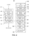
- FIG. 2 is a block diagram explaining a main control system of the impact tester according to the disclosure.
- the impact tester carries out an impact test rapidly applying an impact to a test piece TP, and includes a tester body 10 and a control device 40.
- the tester body 10 includes a table 11, a pair of support posts 12 erected on the table 11, a cross yoke 13 bridged over the pair of support posts 12, and a hydraulic cylinder 31 fixed to the cross yoke 13.
- the hydraulic cylinder 31 is operated by operating oil supplied via a servo valve 34 from a hydraulic source (not illustrated) disposed in the table 11.
- An upper gripper 21 is connected to a piston rod 32 of the hydraulic cylinder 31 via an approach jig 25 and a joint 26.
- a lower gripper 22 is connected to the table 11 via a load cell 27 being a force detector.
- the configuration of the tester body 10 is a configuration for carrying out a tensile impact test in which, by providing an approach section in a tensile direction by the approach jig 25 and pulling up the piston rod 32 at a high speed of 0.1 m/s to 20 m/s, a pair of grippers that grip both ends of the test piece TP are rapidly separated.
- a displacement (stroke) of a load structure, i.e., a movement amount of the piston rod 32, at the time when the tensile impact test is carried out is detected by a stroke sensor 33, and force at that time is detected by the load cell 27.
- the control device 40 includes a body control device 41 for controlling operation of the tester body 10, and a personal computer 42.
- the body control device 41 includes a memory 43 storing programs, an arithmetic device 45 such as a micro processing unit (MPU) or the like performing various operations, and a communication section 46 communicating with the personal computer 42.
- the memory 43, the arithmetic device 45 and the communication section 46 are connected to one another by a bus 61.
- the body control device 41 includes a test control section 44 as a functional configuration.
- the test control section 44 is stored as a test control program in the memory 43.
- the personal computer 42 includes a memory 51 consisting of a read-only memory (ROM) that stores a data analysis program, a random access memory (RAM) that loads a program and temporarily stores data when executing the program and so on, an arithmetic device 55 such as a central processing unit (CPU) or the like performing various operations, a communication section 56 communicating with an external connection machine such as the body control device 41 or the like, a memory device 57 storing data, a display device 58 and an input device 59.
- the memory device 57 is a memory section storing time-series data of force of an impact test and so on, and is composed of a large capacity memory device such as a hard disk drive (HDD) or the like.
- the memory 51, the arithmetic device 55, the communication section 56, the memory device 57, the display device 58 and the input device 59 are connected to one another by a bus 71.
- the personal computer 42 includes, as a functional configuration, a data extraction section 52 extracting from the time-series data of the force a data section for obtaining a natural frequency of the impact tester in a later-described natural vibration analysis, an analysis section 53 carrying out a frequency spectrum analysis on the extracted data section, and a vibration waveform removal section 54 removing a natural vibration waveform of the impact tester from force data.
- the data extraction section 52, the analysis section 53 and the vibration waveform removal section 54 are respectively stored as a data extraction program, an analysis program and a vibration waveform removal program in the memory 51. These programs are executed due to the action of the arithmetic device 55.
- the force detected by the load cell 27 when the tensile impact test is carried out is input to the memory 43 of the body control device 41, and then sent from the communication section 46 to the personal computer 42.
- the force received by the communication section 56 of the personal computer 42 is stored as time-series data in the memory device 57.
- FIG. 3 is a flowchart showing a natural vibration measurement procedure. This flowchart shows the measurement procedure of the natural vibration in a tensile impact test using a synthetic resin piece such as polypropylene (PP), polycarbonate (PC), polystyrene (PS) or the like as the test piece TP.
- a synthetic resin piece such as polypropylene (PP), polycarbonate (PC), polystyrene (PS) or the like as the test piece TP.
- test conditions are set (step S11).
- a user sets the test conditions such as test speed and so on using the input device 59 of the personal computer 42.
- both ends of the test piece TP are gripped by the upper gripper 21 and the lower gripper 22 (step S12).
- step S13 data acquisition conditions are set.
- the user sets data collection conditions, such as data collection start time and data collection end time, sampling frequency, number of acquired data points (number of sampling points) and so on, using the input device 59 of the personal computer 42.
- the natural vibration that occurs in the tester body 10 during testing can be acquired by observing vibrations that become noticeable when a load applied to the load cell 27 via the test piece TP is removed due to breakage.
- the force in a state of receiving weight of a test jig in this embodiment, the lower gripper 22 also needs to be known.
- the data collection start time and the data collection end time it is preferable to set so that the data can be acquired before a tensile load is applied to the test piece TP and that a sufficient number of data points (e.g., a number of data points in which the number of data points after breakage of the test piece TP becomes 1000 points or more) for the later-described spectrum analysis can be obtained.
- a sufficient number of data points e.g., a number of data points in which the number of data points after breakage of the test piece TP becomes 1000 points or more
- ⁇ f represents the frequency resolution
- T represents a time window length
- Fs represents the sampling frequency
- N represents the number of sampling points.
- step S14 a test is carried out.
- the force detected by the load cell 27 during a period from the data collection start time to the data collection end time set in the data acquisition conditions is sent to the personal computer 42 via the body control device 41 and saved in the memory device 57, and the measurement is ended (step S15).
- FIG. 4 is a graph showing an example of time-series data of force.
- FIG. 5 is a graph showing by enlarging a waveform before and after breakage of the test piece TP in the graph of FIG. 4 .
- the vertical axis represents force (kN: kilonewton); the horizontal axis represents time ( ⁇ s: microsecond).
- time-series data of the force obtained by carrying out the test whether or not there is a sufficient number of data points for the later-described spectrum analysis can be confirmed using expression (1).
- a starting point of the data after breakage can be set to, for example, time T 1 at which one and half periods of the vibration waveform have elapsed, as shown in FIG. 5 .
- the test piece TP is replaced (step S12), the settings of the data acquisition conditions are changed (step S13) and the test is carried out again (step S14).
- FIG. 6 is a flowchart showing a natural frequency analysis procedure.
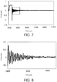
- FIG. 7 is a graph showing an example of time-series data of force.
- FIG. 8 is a graph showing time-series data after breakage of the test piece TP.
- the vertical axis represents force (kN: kilonewton); the horizontal axis represents time ( ⁇ s: microsecond).
- the time-series data of the force acquired in accordance with the measurement procedure shown in FIG. 3 is read from the memory device 57, and the time-series data is separated before and after the force is removed from the test piece TP (step S21).
- the graph shown in FIG. 7 is the force data acquired by carrying out the tensile impact test under the condition of a test speed of 5 m/s at a sampling frequency of 1000 kHz.
- the time-series data is separated into before breakage of the test piece TP and after breakage of the test piece TP.
- time T 1 is determined as explained with reference to FIG.
- step S22 data extraction step
- FFT fast Fourier transform
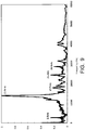
- FIG. 9 is a graph showing a frequency spectrum analysis result of the time-series data shown in FIG. 8 .
- the horizontal axis represents frequency (Hz: hertz); the vertical axis represents power per frequency resolution ⁇ f.
- the frequency spectrum analysis result is displayed on the display device 58 and stored in the memory device 57.
- the frequency 13.8 kHz having the largest peak is set as the natural frequency (step S24).
- FIG. 10 is a flowchart showing a procedure for removing the natural frequency from time-series data.
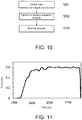
- FIG. 11 is a graph showing time-series data before breakage of the test piece TP;
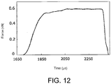
- FIG. 12 is a graph showing data obtained by removing the natural frequency from the time-series data in FIG. 11 .
- the vertical axis represents force (kN: kilonewton);
- the horizontal axis represents time ( ⁇ s: microsecond).
- step S31 a data range for removing the natural vibration waveform is selected (step S31), and the natural vibration of the impact tester considered to overlap the data is removed from the time-series data by using a moving average process (step S32: vibration waveform removal step).
- the time-series data before breakage of the test piece TP which contains time data of a state in which a tension load is applied to the test piece TP, is called from the memory device 57 as target data from which the natural frequency is to be removed.
- the time-series data before data separation may be selected.
- step S32 according to the following expression (2) that uses the natural frequency determined in step S24 as explained above and the sampling frequency at acquisition of the data, the number of data points used for the moving average process is determined.
- Number of data points sampling frequency / natural frequency
- the data in FIG. 11 is acquired by carrying out the tensile impact test under the condition of a test speed of 5 m/s at a sampling frequency of 1000 kHz. Accordingly, the integer part of a number 72.4 obtained by dividing the sampling frequency 1000 kHz by the natural frequency 13.8 kHz obtained in step S24 is the number of data points. Moreover, as in this example, in the case where a value obtained by dividing the sampling frequency by the integer of the natural frequency is not an integer, the value is made an integer value by truncating or rounding off digits following the decimal point.
- averaging is performed using data of the same amount before and after (including cases where the numbers of points before and after differ by 1) the data intended to be averaged as the center.
- the averaging process is performed using 35 points before and 36 points after the data (the 36-th point) intended to be averaged as the center.
- the data in FIG. 12 shows a smoother behavior. It is understood that, even in the state in which a tension load is applied to the test piece TP, the natural vibration of the impact tester affects a measured value of the load cell 27.
- the moving average process is performed by determining 13.8 kHz corresponding to the largest peak in the frequency spectrum analysis explained with reference to FIG. 9 to be the natural frequency, several peaks may be used as candidates for the natural frequency and the moving average process may be performed on these candidates.
- the evaluation method considering the natural frequency of the impact tester is adopted for evaluation of the impact test, by obtaining a waveform from which noise caused by the natural vibration of the impact tester is removed, it is possible to know an accurate force value.
- the data before and after removal of the natural vibration waveform can be seen on the same time axis, the user can confirm the effect of the natural vibration of the impact tester on force data in each individual impact test.
- the disclosure is also applicable to a punching test in which a punch is caused to collide with a test piece or an impact test such as a three-point bending test in which a punch is struck on a test piece supported by a fulcrum.
Landscapes
- Physics & Mathematics (AREA)
- General Physics & Mathematics (AREA)
- Immunology (AREA)
- Pathology (AREA)
- Chemical & Material Sciences (AREA)
- Analytical Chemistry (AREA)
- Biochemistry (AREA)
- General Health & Medical Sciences (AREA)
- Health & Medical Sciences (AREA)
- Life Sciences & Earth Sciences (AREA)
- Engineering & Computer Science (AREA)
- Signal Processing (AREA)
- Acoustics & Sound (AREA)
- Mathematical Physics (AREA)
- Spectroscopy & Molecular Physics (AREA)
- Manufacturing & Machinery (AREA)
- Investigating Strength Of Materials By Application Of Mechanical Stress (AREA)
Applications Claiming Priority (1)
| Application Number | Priority Date | Filing Date | Title |
|---|---|---|---|
| JP2017118517A JP6930240B2 (ja) | 2017-06-16 | 2017-06-16 | 衝撃試験の評価方法および衝撃試験機 |
Publications (1)
| Publication Number | Publication Date |
|---|---|
| EP3415894A1 true EP3415894A1 (en) | 2018-12-19 |
Family
ID=62636124
Family Applications (1)
| Application Number | Title | Priority Date | Filing Date |
|---|---|---|---|
| EP18177809.3A Withdrawn EP3415894A1 (en) | 2017-06-16 | 2018-06-14 | Evaluation method of impact test and impact tester |
Country Status (4)
| Country | Link |
|---|---|
| US (1) | US20180364139A1 (https=) |
| EP (1) | EP3415894A1 (https=) |
| JP (1) | JP6930240B2 (https=) |
| CN (1) | CN109142100A (https=) |
Families Citing this family (4)
| Publication number | Priority date | Publication date | Assignee | Title |
|---|---|---|---|---|
| JP6866830B2 (ja) * | 2017-11-22 | 2021-04-28 | 株式会社島津製作所 | 材料試験機および把持力検出方法 |
| JP7135932B2 (ja) * | 2019-02-26 | 2022-09-13 | 株式会社島津製作所 | 引張試験機、及び引張試験機の制御方法 |
| JP7306464B2 (ja) * | 2019-09-13 | 2023-07-11 | 株式会社島津製作所 | 引張試験機、及び引張試験機の制御方法 |
| CN115046831B (zh) * | 2022-07-20 | 2023-08-29 | 赛迈科先进材料股份有限公司 | 一种石墨轴向疲劳测试的方法 |
Citations (10)
| Publication number | Priority date | Publication date | Assignee | Title |
|---|---|---|---|---|
| GB118175A (en) * | 1917-09-22 | 1918-08-22 | Avery Ltd W & T | Improvements in Impact Testing Machines. |
| EP1070961A1 (en) * | 1999-07-19 | 2001-01-24 | BRITISH TELECOMMUNICATIONS public limited company | Test apparatus |
| JP2004333143A (ja) | 2003-04-30 | 2004-11-25 | Shimadzu Corp | 衝撃試験機およびその設置構造 |
| JP2004333221A (ja) | 2003-05-02 | 2004-11-25 | Shimadzu Corp | 衝撃引張試験機用スパナ、衝撃引張試験機の試験片装着方法および衝撃引張試験機 |
| EP2120034A1 (en) * | 2008-05-16 | 2009-11-18 | Vrije Universiteit Brussel | Method and apparatus for providing an optimal test panel for the non-destructive measurement of elastic properties of structural materials |
| WO2012004969A1 (ja) * | 2010-07-06 | 2012-01-12 | 信越化学工業株式会社 | 多結晶シリコン棒および多結晶シリコン棒の検査方法ならびに多結晶シリコン棒の製造方法 |
| WO2012153956A2 (en) * | 2011-05-09 | 2012-11-15 | Industry-Academia Cooperation Group Of Sejong University | Impact test apparatus using energy frame |
| US20160084802A1 (en) * | 2014-09-19 | 2016-03-24 | King Fahd University Of Petroleum And Minerals | Process for determining weld quality using flexural characteristics |
| US20170153208A1 (en) * | 2015-11-26 | 2017-06-01 | Dmg Mori Co., Ltd. | Method Of Deriving Natural Frequency Of Cutting Tool, Method Of Creating Stability Limit Curve, And Apparatus For Deriving Natural Frequency Of Cutting Tool |
| EP3415893A1 (en) * | 2017-06-16 | 2018-12-19 | Shimadzu Corporation | Evaluation method of impact test and impact tester |
Family Cites Families (11)
| Publication number | Priority date | Publication date | Assignee | Title |
|---|---|---|---|---|
| JPS5819979B2 (ja) * | 1978-08-01 | 1983-04-21 | 日章電機株式会社 | 材料の動的試験における荷重計測方法および装置 |
| JPH0765954B2 (ja) * | 1986-10-30 | 1995-07-19 | ジャパンセンサー株式会社 | 計装化シャルピー試験機を用いた動的特性測定装置 |
| CA1323683C (en) * | 1988-09-30 | 1993-10-26 | Michel J. Pettigrew | Loose rock detector |
| JPH03211457A (ja) * | 1990-01-16 | 1991-09-17 | Toyota Motor Corp | 割れ検出方法 |
| JP2941150B2 (ja) * | 1993-07-27 | 1999-08-25 | 株式会社奥村組 | 岩盤の性状測定装置 |
| US5400640A (en) * | 1993-10-29 | 1995-03-28 | International Business Machines Corporation | Pyrotechnic shock machine |
| JP2002333437A (ja) * | 2001-05-10 | 2002-11-22 | Mitsubishi Heavy Ind Ltd | 打撃検査装置 |
| JP4033119B2 (ja) * | 2003-12-10 | 2008-01-16 | 株式会社島津製作所 | 材料の試験方法、材料試験機 |
| US20080295602A1 (en) * | 2007-06-01 | 2008-12-04 | Gavin Wallace | Method and System for Sorting Green Lumber |
| JP5824858B2 (ja) * | 2010-05-10 | 2015-12-02 | Jfeスチール株式会社 | 溶接部の組織形状の画像化方法及びその装置 |
| JP5527696B2 (ja) * | 2010-09-27 | 2014-06-18 | 地方独立行政法人大阪府立産業技術総合研究所 | 衝撃強さ評価装置、方法およびプログラム |
-
2017
- 2017-06-16 JP JP2017118517A patent/JP6930240B2/ja active Active
-
2018
- 2018-06-14 EP EP18177809.3A patent/EP3415894A1/en not_active Withdrawn
- 2018-06-15 CN CN201810617873.5A patent/CN109142100A/zh not_active Withdrawn
- 2018-06-15 US US16/009,220 patent/US20180364139A1/en not_active Abandoned
Patent Citations (10)
| Publication number | Priority date | Publication date | Assignee | Title |
|---|---|---|---|---|
| GB118175A (en) * | 1917-09-22 | 1918-08-22 | Avery Ltd W & T | Improvements in Impact Testing Machines. |
| EP1070961A1 (en) * | 1999-07-19 | 2001-01-24 | BRITISH TELECOMMUNICATIONS public limited company | Test apparatus |
| JP2004333143A (ja) | 2003-04-30 | 2004-11-25 | Shimadzu Corp | 衝撃試験機およびその設置構造 |
| JP2004333221A (ja) | 2003-05-02 | 2004-11-25 | Shimadzu Corp | 衝撃引張試験機用スパナ、衝撃引張試験機の試験片装着方法および衝撃引張試験機 |
| EP2120034A1 (en) * | 2008-05-16 | 2009-11-18 | Vrije Universiteit Brussel | Method and apparatus for providing an optimal test panel for the non-destructive measurement of elastic properties of structural materials |
| WO2012004969A1 (ja) * | 2010-07-06 | 2012-01-12 | 信越化学工業株式会社 | 多結晶シリコン棒および多結晶シリコン棒の検査方法ならびに多結晶シリコン棒の製造方法 |
| WO2012153956A2 (en) * | 2011-05-09 | 2012-11-15 | Industry-Academia Cooperation Group Of Sejong University | Impact test apparatus using energy frame |
| US20160084802A1 (en) * | 2014-09-19 | 2016-03-24 | King Fahd University Of Petroleum And Minerals | Process for determining weld quality using flexural characteristics |
| US20170153208A1 (en) * | 2015-11-26 | 2017-06-01 | Dmg Mori Co., Ltd. | Method Of Deriving Natural Frequency Of Cutting Tool, Method Of Creating Stability Limit Curve, And Apparatus For Deriving Natural Frequency Of Cutting Tool |
| EP3415893A1 (en) * | 2017-06-16 | 2018-12-19 | Shimadzu Corporation | Evaluation method of impact test and impact tester |
Also Published As
| Publication number | Publication date |
|---|---|
| JP6930240B2 (ja) | 2021-09-01 |
| US20180364139A1 (en) | 2018-12-20 |
| JP2019002828A (ja) | 2019-01-10 |
| CN109142100A (zh) | 2019-01-04 |
Similar Documents
| Publication | Publication Date | Title |
|---|---|---|
| EP3415893A1 (en) | Evaluation method of impact test and impact tester | |
| EP3415894A1 (en) | Evaluation method of impact test and impact tester | |
| EP3521799B1 (en) | Test result evaluating method and material tester | |
| EP3521801B1 (en) | Test result evaluating method and a kit comprising a material tester and a hammer | |
| KR101179134B1 (ko) | 고속충돌 음향방출 측정 시스템 및 그 방법 | |
| US10871408B2 (en) | Noise removal method of material test and material testing machine | |
| CN105387987A (zh) | 人工高频机械冲击试验设备 | |
| CN104913988B (zh) | 基于霍普金森原理的混凝土轴心抗拉强度测量方法 | |
| JP2019002828A5 (https=) | ||
| EP3141305A1 (en) | Experimental method to detect the elastic modulus of objects, samples or semi-worked products of various materials | |
| JPH10153504A (ja) | 杭の動的載荷試験法 | |
| Söver et al. | High impact-testing machine for elastomers investigation under impact loads | |
| CN104180985A (zh) | 提综刀频谱曲线测量方法及其装置 | |
| JP6504964B2 (ja) | 部材の状態評価装置および状態評価方法 | |
| RU145160U1 (ru) | Разгонный отсек стенда для ударных испытаний | |
| RU2402767C2 (ru) | Способ испытания асфальтобетонных смесей на слеживаемость | |
| RU2670723C1 (ru) | Способ определения напряженно-деформированного состояния различных упругих объектов | |
| Brasiliano et al. | Output-only modal testing of a laboratory test footbridge | |
| Jayashankar et al. | Output only modal analysis of engineering structures | |
| NEDELCU et al. | The estimation of dynamic properties of a fixed beam using experimental modal testing | |
| CN120352280A (zh) | 一种建筑结构试验检测方法 | |
| Ghods et al. | Damage assessment of reinforced concrete beams by modal test | |
| Subhaprakash | Modal and Buckling Analysis of a Cracked Cantilever Beam with Circular Cross Section | |
| Renning et al. | On the influence of boundary conditions on the modal properties of a base frame | |
| O'Leary | Dynamic characterisation of cellular cores and sandwich beams |
Legal Events
| Date | Code | Title | Description |
|---|---|---|---|
| PUAI | Public reference made under article 153(3) epc to a published international application that has entered the european phase |
Free format text: ORIGINAL CODE: 0009012 |
|
| STAA | Information on the status of an ep patent application or granted ep patent |
Free format text: STATUS: REQUEST FOR EXAMINATION WAS MADE |
|
| 17P | Request for examination filed |
Effective date: 20180614 |
|
| AK | Designated contracting states |
Kind code of ref document: A1 Designated state(s): AL AT BE BG CH CY CZ DE DK EE ES FI FR GB GR HR HU IE IS IT LI LT LU LV MC MK MT NL NO PL PT RO RS SE SI SK SM TR |
|
| AX | Request for extension of the european patent |
Extension state: BA ME |
|
| STAA | Information on the status of an ep patent application or granted ep patent |
Free format text: STATUS: EXAMINATION IS IN PROGRESS |
|
| 17Q | First examination report despatched |
Effective date: 20210907 |
|
| STAA | Information on the status of an ep patent application or granted ep patent |
Free format text: STATUS: THE APPLICATION HAS BEEN WITHDRAWN |
|
| 18W | Application withdrawn |
Effective date: 20220106 |