EP3415676A2 - Calendar - Google Patents
Calendar Download PDFInfo
- Publication number
- EP3415676A2 EP3415676A2 EP18181952.5A EP18181952A EP3415676A2 EP 3415676 A2 EP3415676 A2 EP 3415676A2 EP 18181952 A EP18181952 A EP 18181952A EP 3415676 A2 EP3415676 A2 EP 3415676A2
- Authority
- EP
- European Patent Office
- Prior art keywords
- roller
- pivot
- nip
- calender
- frame
- Prior art date
- Legal status (The legal status is an assumption and is not a legal conclusion. Google has not performed a legal analysis and makes no representation as to the accuracy of the status listed.)
- Granted
Links
- 238000012546 transfer Methods 0.000 claims description 14
- 239000004753 textile Substances 0.000 claims description 6
- 238000003490 calendering Methods 0.000 claims description 5
- 239000004033 plastic Substances 0.000 claims description 5
- -1 nonwoven Substances 0.000 claims description 3
- 230000008859 change Effects 0.000 description 21
- 238000006073 displacement reaction Methods 0.000 description 13
- 239000011248 coating agent Substances 0.000 description 9
- 238000000576 coating method Methods 0.000 description 9
- 238000003860 storage Methods 0.000 description 9
- 230000015572 biosynthetic process Effects 0.000 description 8
- 230000032258 transport Effects 0.000 description 8
- 238000003825 pressing Methods 0.000 description 6
- 230000008901 benefit Effects 0.000 description 5
- 238000004519 manufacturing process Methods 0.000 description 5
- 239000000123 paper Substances 0.000 description 5
- 238000011144 upstream manufacturing Methods 0.000 description 5
- 230000005484 gravity Effects 0.000 description 4
- 238000010438 heat treatment Methods 0.000 description 4
- 238000005461 lubrication Methods 0.000 description 4
- 238000011282 treatment Methods 0.000 description 4
- 238000001816 cooling Methods 0.000 description 3
- 239000010687 lubricating oil Substances 0.000 description 3
- 239000000463 material Substances 0.000 description 3
- 229920000742 Cotton Polymers 0.000 description 2
- 238000006243 chemical reaction Methods 0.000 description 2
- 238000010276 construction Methods 0.000 description 2
- 238000013461 design Methods 0.000 description 2
- 239000004744 fabric Substances 0.000 description 2
- 239000004745 nonwoven fabric Substances 0.000 description 2
- 239000003921 oil Substances 0.000 description 2
- 238000013459 approach Methods 0.000 description 1
- 230000008878 coupling Effects 0.000 description 1
- 238000010168 coupling process Methods 0.000 description 1
- 238000005859 coupling reaction Methods 0.000 description 1
- 239000000314 lubricant Substances 0.000 description 1
- 238000012423 maintenance Methods 0.000 description 1
- 238000000034 method Methods 0.000 description 1
- 230000008569 process Effects 0.000 description 1
- 238000012545 processing Methods 0.000 description 1
- 238000007711 solidification Methods 0.000 description 1
- 230000008023 solidification Effects 0.000 description 1
- 230000035882 stress Effects 0.000 description 1
- 230000003685 thermal hair damage Effects 0.000 description 1
- 230000008646 thermal stress Effects 0.000 description 1
Images


Classifications
-
- D—TEXTILES; PAPER
- D06—TREATMENT OF TEXTILES OR THE LIKE; LAUNDERING; FLEXIBLE MATERIALS NOT OTHERWISE PROVIDED FOR
- D06C—FINISHING, DRESSING, TENTERING OR STRETCHING TEXTILE FABRICS
- D06C15/00—Calendering, pressing, ironing, glossing or glazing textile fabrics
- D06C15/02—Calendering, pressing, ironing, glossing or glazing textile fabrics between co-operating press or calender rolls
-
- D—TEXTILES; PAPER
- D21—PAPER-MAKING; PRODUCTION OF CELLULOSE
- D21G—CALENDERS; ACCESSORIES FOR PAPER-MAKING MACHINES
- D21G1/00—Calenders; Smoothing apparatus
-
- D—TEXTILES; PAPER
- D21—PAPER-MAKING; PRODUCTION OF CELLULOSE
- D21G—CALENDERS; ACCESSORIES FOR PAPER-MAKING MACHINES
- D21G1/00—Calenders; Smoothing apparatus
- D21G1/002—Opening or closing mechanisms; Regulating the pressure
-
- D—TEXTILES; PAPER
- D21—PAPER-MAKING; PRODUCTION OF CELLULOSE
- D21G—CALENDERS; ACCESSORIES FOR PAPER-MAKING MACHINES
- D21G1/00—Calenders; Smoothing apparatus
- D21G1/0073—Accessories for calenders
- D21G1/0086—Web feeding or guiding devices
Definitions
- the invention relates to a calender, with a frame in which a plurality of upper rollers and at least one lower roller are mounted.
- Replacing a roller is often expensive, especially for simple calenders. Numerous manual work is necessary. Mention should be the drive, the bearing lubrication, possibly the heater and of course the support of the roller. If the roller is heated, the roller to be replaced must first be time-consuming cooled and the new roller to be heated before starting production. Long downtimes and production downtimes are the result. For the fast roll change provided calender types are often expensive or require an enlarged roll diameter. In some variants, only one alternative roller is available for one or both of a nip roll. Some quick-change calenders are not suitable for certain types of applications, such as calendering fleece.
- the invention has set itself the task of creating a calender in which at least one roller of a nip can be exchanged quickly and which is improved in terms of at least one of the disadvantages mentioned.
- the calender according to the invention has a frame in which a plurality of top rollers and at least one bottom roller are mounted.
- the at least one lower roller can form a nip with a top roller.
- an inlet-side nip and an outlet-side nip can be provided by the calender.
- an inlet side and an outlet side nip can be provided by the calender at the same time.
- only one inlet-side or one outlet-side nip can be provided by the calender at a time.
- At least one lower roller is preferably provided with its own feed device, with which it can preferably be moved toward and away from an upper roller, particularly preferably translationally.
- the delivery device may comprise a hydraulic cylinder.
- delivery device and “delivery device” are synonymous in the context of this document.
- the calender serves to thermally strengthen nonwoven fabrics. It can act as a smooth roller against an engraved roller. Also, both rolls of a nips can be engraved. At least one of the two rolls of a nip can be heated. In order to produce different products, preferably the engraved roll is quickly exchangeable. In one embodiment, only the top roll of a nip is engraved.
- the calender is used for calendering paper or textile.
- a roller with a coating acts against a heated smooth or even engraved roller.
- cover are in the context of this Reference document on the one hand meant in particular rollers which have a resilient coating and on the other hand, in particular, in a wide use of this term, also cotton rollers.
- a quick exchange of the engraving may be desired. More often, however, there is a need to replace the pad to bring a different type or coating hardness used or regrind this, since wear takes place mainly on the softer pad.
- a rapid temperature change of the roll surface of at least one roll of a nip can be brought about by the roll change. This is preferably done without exceeding a temperature change in a roll of 1 to 10 K / min, since otherwise thermoelectric stresses in the roll material are to be feared.
- the calender allows a quick replacement of a roller, without manual intervention.
- a roller exchange in a shorter time than the heating or heating of the roller is possible.
- At least one lower roller is provided, which can be brought into two different working positions and more preferably forms a nip with different upper rollers.
- at least two different lower roller positions are preferably provided, of which only one is preferably selected at a time.
- Exactly one lower roller can therefore preferably; in one embodiment only sequentially; form two different nips whose position preferably differs from each other.
- the lower roller is provided tiltable and / or displaceable, preferably to serve the upstream side upper roller or the outlet side upper roller or two upper rollers simultaneously.
- outlet side is in the context of this document in particular the side of the calender designates, at which the goods enters the calender.
- outlet side is in the context of this document in particular the side of the calender designation, at which the goods leave the calender.
- a lower roller of the calender is arranged on a pair of rocker arms.
- the two rocker arms of this rocker arm pair are preferably only tiltable in pairs.
- This rocker arm pair preferably has two different end positions, in which, in each case, a contact surface of the pair of rocker arms more preferably bears against a counter-bearing surface of the frame.
- the tilting axis of the rocker arm pair is preferably located between the press plane of the inlet-side nip and the press plane of the outlet-side nip.
- the two end positions which occupies the lower roller in the two end positions of the Kipphebelpases, the two working positions of the lower roller, in which this preferably forms a nip with the associated upper roller.
- the calender comprises exactly one lower roller.
- the calender comprises more than one lower roll.
- more than one additional roll of a nip is kept ready for replacement.
- the calender comprises exactly two lower rolls, which are more preferably deliverable independently of one another.
- the feed movement of the lower rollers is preferably translational, preferably exclusively.
- At least one lower roller of the calender - with the exception of the feed movement - not displaced.
- the temperature or the surface quality of the lower roller can be changed quickly.
- the frame can be viewed from the side formed at least approximately "U" -shaped.
- the clear width of the "U" -shaped frame or frame part can be greater than twice the diameter of the lower roller.
- the entire frame is formed stationary.
- the frame has a first stationary frame part and a second frame part, wherein the second frame part is provided so as to be displaceable relative to the first frame part.
- the second frame part viewed from the side may be formed at least approximately "U" -shaped.
- the goods feeder and the goods conveyor belt can always remain in the same position in this embodiment. The position of the goods feed and the goods conveyor belt can therefore be designed unchangeable.
- the nips may be inclined so that the fabric may leave the nip without further contact with the roll surfaces.
- At least one - preferably exactly one - lower roller is mounted on the first frame part and more preferably at least one upper roller - preferably all upper rollers - mounted on the second frame part.
- the At least one top roller is preferably not mounted directly on the second frame part.
- the second frame part is preferably mounted on the first frame part, preferably displaceable and / or tiltable.
- the second frame part is displaceably mounted relative to the first frame part by means of a thrust bearing.
- the thrust bearing may comprise a linear bearing, so allow a linear displacement. Also, a storage that allows a displacement along a curved line is conceivable in principle.
- the thrust bearing preferably comprises a carriage and / or rail arrangement.
- the thrust bearing is preferably arranged partially or completely below the lower roller.
- the tilting bearing is preferably arranged below the lower roller.
- the second frame part is preferably in - preferably two - different positions can be brought relative to the first frame part, in which a lower roller with different top rollers forms a nip.
- the calendar has at least one Walzenlagerungsschwenkhebelcru - in one embodiment exactly a Walzenlagerungsschwenkhebelcru - on the at least one upper roller - in one embodiment exactly one upper roller - is arranged.
- Such Walzenlagerungsschwenkhebelcru is referred to in the context of this document also briefly as Schwenkhebelcru and a Walzenlagerungsschwenkhebel of such a pair is also referred to as a pivoting lever in the context of this document.
- the pivot lever of a pivot lever pair are preferably only in pairs pivotable. With this at least one pivot lever pair is preferably at least one upper roller of a Parking position pivoted into a working position.
- the at least one pivot lever pair is preferably pivotable into a working position, in which the at least one roller arranged on it is in a working position.
- the at least one pair of pivot levers is also preferably pivotable into a parking position, in which the at least one roller arranged on it is in a parking position.
- a "working position" of a roller is in the context of this document, in particular the position of a roller referred to, in which it forms or forms a nip with a counter-roller.
- the at least one pivot lever pair can be pivoted by approximately 90 °.
- the calender has a first pair of pivot levers and a second pair of pivot levers.
- each pivot lever pair is mounted pivotably about a pivot axis on the frame.
- Each pivot lever pair preferably provides a support for a roller.
- the rollers arranged on the at least one pair of pivot levers are thus mounted on the frame of the calender via the pivot lever pair.
- the supply of the bearings of the at least one pair of pivot lever arranged upper rollers is easy to solve. Because the bearing body are preferably only rotated by an angle of about 90 °. Advantageously, a bearing lubrication is realized without contacting seals and consequently unpressurized, following only the gravity oil drain. Since the bearing bodies are preferably rotated only by an angle of about 90 °, the bearing lubricating oil drains and bearing lubricating oil return lines with gravity feed are easy to carry out.
- At least two top rollers are mounted on the first pair of pivot levers and / or the second pair of pivot levers.
- At least two upper rollers are mounted both on the first pivot lever pair, and on the second pair of pivot levers.
- each upper roller is preferably so far away from the lower roller, that a movement of the at least one arranged on the other pair of pivot lever roller from the working position in the parking position and vice versa is possible.
- the working positions of at least two different top rollers match.
- the upper rollers are preferably displaceable together with their drive and possibly supply device.
- the number of bottom rollers corresponds to the number of top rollers mounted in a pivoting lever.
- the pivot lever pair is preferably mounted on the second frame part.
- both swivel lever pairs are preferably mounted on the second frame part.
- the at least one top roller is thus preferably mounted by means of at least one pair of pivot levers on the second frame part.
- each pivot lever can advantageously be locked on the side of a press plane of a nip opposite its pivot axis. This is preferably realized such that the opposite pivot lever is initially pivotable beyond the park position, then the pivot lever can be brought into the working position and the opposite pivot lever back to its parking position is displaced and thereby locks the pivot lever. More preferably, the locking takes place in that each pivot lever has a pivot axis near stop surface and a pivot axis remote stop surface and the pivot axis near stop surface of the pivot lever in its parking position with advantage on the pivot axis remote stop surface is located in a working position pivot lever. In other words, each pivoting lever located in the working position is preferably lockable on a pivoting lever located in parking position.
- each pivot lever can be brought into a release position.
- the parking position of each pivot lever is preferably between its release position and its working position.
- each pivot lever in its release position is just so far inclined that the other pivot lever can be brought collision-free against the first pivot lever in its parking position.
- the pivot lever are designed as two-armed lever in which on one side of the pivot axis at least one upper roller is arranged and on the other side preferably engages a pivot drive.
- Each pivot lever is preferably double-walled and further preferably surrounds a bearing lug of the frame on both sides.
- the upper rollers are releasably attached to the pivot levers.
- the top rollers can be engraved. However, the top rollers can also be smooth. Also, the at least one lower roller can be engraved or smooth. All or individual rolls can be flexurally controllable.
- the calender can have both conventional small line force rolls and flexurally controllable rolls for higher forces or higher accuracies.
- a heating and cooling of the rollers in their parking position is possible.
- rollers of the calender can be equipped with a direct drive.
- the working positions of all top rollers are arranged at a height.
- the calender is intended for nonwoven goods. More specifically, in this embodiment, the calender serves to thermally solidify nonwoven fabrics.
- the web is deposited and formed on a goods conveyor belt of a goods feed only immediately prior to solidification in the calender.
- the goods feed is preferably up to less than 10 cm or 5 cm approach the nip forming rollers.
- the calender has a goods feed, which more preferably comprises a goods conveyor belt, and the goods feed is preferably carried out as a nonwoven feed.
- the goods conveyor belt is therefore preferably used to transport the web.
- the goods conveyor belt is aligned at least substantially horizontally.
- the remainder of the calender is skewed in one embodiment to make room for this fabric conveyor, particularly when the downstream nip is active.
- the nips can be so inclined.
- the remaining calender is arranged obliquely, it is preferably inclined slightly downwards in the goods transport direction.
- good feed refers in particular to a device which transports goods to be calendered, preferably fleece, until immediately before the nip.
- the goods feed may comprise a screen belt, with a Siebbandumlenkwalze as close as possible to the respective nip is arranged.
- the goods conveyor belt is arranged obliquely in the region in front of the respective nip, preferably obliquely in the goods transport direction up. In this way, the goods conveyor belt - especially when it operates the outlet side nip - reach closer to the nip zoom.
- the top rollers may have working positions which are provided at different heights.
- the working position of the outlet side upper roller is provided lower than the working position of the upstream side upper roller.
- the inlet-side upper roller if the outlet-side nip is realized, creates space for the goods conveyor belt.
- the top rollers are thus preferably arranged offset in height at the respective pivot lever pair.
- this is preferably effected by tilting the calender.
- the position of the goods conveyor belt is designed changeable.
- the change of the position of the goods conveyor belt is preferably coupled with the movement of the lower roller.
- the goods feed comprises an additional transfer belt, which preferably extends as far as directly to the nip and whose position is preferably provided changeable. It may be provided a suction roller for transferring the goods from the rest of the goods feed on the transfer belt.
- the transfer belt and the lower roller may be connected and movable at the same time.
- the goods feed may comprise a deflection roller, which causes a deflection of the goods conveyor belt in the area in front of the nip upwards and preferably acts from above on the goods conveyor belt and the goods.
- a lower roller may be designed as an alternative roller, which with a Evasive movement can be brought into an alternative position.
- This is advantageously the inlet-side lower roller.
- the evasive movement is preferably translational.
- the avoidance position is preferably arranged below the parking position of the lower roller.
- the evasive movement preferably comprises a distance that is greater than the radius of the backup roller. In other words, therefore, the inlet-side nip can be provided with a larger stroke so that a goods feed can come as close as possible to the outlet-side nip.
- the evasive movement can be realized by means of a telescopic cylinder.
- rollers can be heated or cooled in their parking position
- drives are preferably also provided for these positions.
- the rollers must rotate constantly to avoid permanent deformation.
- the drives which are normally located on a separate drive block, do not have to be moved with the rollers, at least one roller drive can be designed as a direct drive.
- the pivot drive of the pivot lever may comprise a Spindelhubgetriebe.
- this pivoting drive comprises a hydraulic cylinder.
- exactly one, several or all lower rollers can each be brought into only one working position.
- exactly one, several or all upper rollers are not arranged on a pivot lever, but stored non-pivotably in the frame.
- the calender comprises exactly one pivot lever, on which at least one - preferably exactly two - upper rollers are arranged, which by means of the pivot lever from a parking position into a working position are pivotable.
- this embodiment is less expensive.
- the at least one lower roller is easier to remove by pivoting the pivot lever and, as preferred, another pivot lever with at least one top roller can be retrofitted.
- the Kipphebelbin a motorized pivot lever actuating device, which may for example comprise a hydraulic cylinder.
- the press plane of a nip passes through the axes of the rolls involved in this nip. In one embodiment, all press planes of the calender are perpendicular.
- At least one press plane - preferably all press planes - of the calender is not perpendicular, but oblique.
- the pivot axis of the Kipphebelbins is located exactly midway between the two press levels of the two realizable nips.
- the pivot axis of the rocker arm pair is arranged closer to the entry-side press plane than the exit-side press plane, particularly in the embodiment in which the upstream side upper roller is higher than the downstream side lower roller.
- each lower roller is arranged below all working positions of the upper rollers.
- the bottom roll in one embodiment comprises a first roll, regardless of its arrangement.
- the first roller may thus be arranged above or below other rollers.
- the top rollers in one embodiment comprise a second roller, regardless of their arrangement.
- the second roller can thus be arranged above or below other rollers.
- the top rollers in one embodiment comprise a third roller, regardless of their arrangement.
- the third roller can thus be arranged above or below other rollers.
- the top rollers in one embodiment comprise a fourth roller, regardless of their arrangement.
- the fourth roller may therefore be arranged above or below other rollers.
- the top rollers in one embodiment comprise a fifth roller, regardless of their arrangement.
- the fifth roller may therefore be arranged above or below other rollers.
- the invention also relates to a calender, in particular for textile, nonwoven, plastic or paper webs, with a frame in which a first roller, a second roller and a third roller are mounted, wherein the first roller in the operation of the calender either forms with the second roller or with the third roller a nip, through which the web is guided, to which the second roller between a working position, in which it forms a nip with the first roller, and a parking position is displaceable, and the third roller between a working position in which it forms a nip with the first roller, and a parking position is displaceable, wherein the second roller over first Pivoting lever is mounted on the frame, wherein each pivot lever is pivotable about a pivot axis.
- Such a calender is from the DE 100 05 306 C1 known.
- calenders in particular those for the treatment of textiles, fleece, plastic or paper webs, there is often the need to exchange one of the two nip forming rollers through which the web is passed for treatment.
- rolls with different surface qualities of the roll shell, such as different engravings, coverings of different types and / or hardness, are required for certain treatments.
- roller with a coating acts against a mostly smooth or even engraved roller.
- roller with a coating are particularly to be understood rollers whose acting on the web surface of a surface applied to the roller body coating of, for example, plastic, rubber or cotton is formed.
- a quick replacement of a gravure roll may be desired.
- an incentive for a quick and easy roll change may be to bring about a rapid temperature change of the working surface of a roll.
- a temperature change to avoid thermal stresses in the roll material is only possible with 1 to 3 K / min. If there is the option of a quick roll change, different high-preheated rolls can be kept available and, if necessary, a temperature change can be exchanged.
- a calender in which a plurality of rollers are mounted in a rotatable about an axis parallel to the longitudinal extent of the nip axis rotatable device. By rotating this device about the axis, the various rollers can be selectively shifted between a working position in which they form the nip together with another roller, and a parking position.
- the invention is therefore based on the object, from the DE 100 05 306 C1 known calender with respect to the associated with its production effort and / or to improve the possibilities provided with him possibilities of roller replacement.
- the third roller, as well as the second roller, mounted on the frame via the first pivot lever.
- the effort required for the second pivot lever can be saved.
- the second and third rollers are preferably arranged to be displaceable relative to the first pivoting levers.
- the second and third rollers may preferably be arranged to be displaceable along a cam track, such that the second or third roller are spaced from the web passing through the nip when the respective roller is in its parking position. Due to this measure, it is ensured that the roller located in its parking position does not affect the processing result achieved with the calender. It is therefore alternatively possible to use the second or the third roller for nip formation together with the first roller without having to change the material web course for this purpose.
- the second and third rolls are displaced relative to the first pivot levers.
- the second and third rollers are relative to the first pivoting levers fixed (but rotatable and interchangeable) provided.
- the displacement of the pivot axis of the first pivot lever is oblique to the plane defined by the web path in front of the nip.
- the bearings define the positions of the pivot axes of the first pivot levers.
- These storage facilities may in particular each comprise at least one bearing block.
- a rail arrangement is preferably provided for each bearing block, which extends obliquely to a plane which is oriented perpendicular to the plane in which lie the roll axes of the nip forming rollers.
- a fourth roller is provided in a particularly preferred embodiment of the calender according to the invention, which between a working position in which they the first roller forms a nip, and a parking position is displaceable, wherein the fourth roller is mounted on the frame via second pivot lever, wherein each pivot lever is pivotable about a pivot axis.
- a fifth roller which is mounted on the frame via a second pivoting lever between a working position in which it forms a nip with the first roller and is displaceable to a parking position.
- the second pivot lever can then in particular and preferably analogous to the first pivot lever, but with respect to a through the central longitudinal axes of the nip forming rolls going plane to be formed mirror-image.
- the fourth and fifth rollers may preferably be arranged to be displaceable along a cam track such that the fourth or the fifth roller are spaced from the web passing through the nip when the respective roller is in its rest position.
- the pivot axes of the second pivot lever may be arranged displaceable relative to the frame, preferably in directions which extend obliquely to the plane which is defined by the web immediately behind the nip.
- frame-side bearing devices that define the pivot axes of the second pivot lever can be provided. These may be displaceable along rail arrangements provided on the frame which are oblique to the plane which is oriented perpendicular to the plane in which the roll axes of the rolls forming the nip lie.
- the first pivot lever and the second pivot lever on locking means.
- These locking devices are designed in such a way that the second pivot levers located in a parking position lock the first pivot levers located in their working position and vice versa. That is, the first pivot lever located in a parking position lock the first pivot lever located in its working position.
- the invention includes the features mentioned in this document in all combinations.
- the goods transport direction runs in the FIGS. 1 to 9 and 11 to 19 left to right.
- the goods transport direction also runs in the FIGS. 20 to 25 left to right.
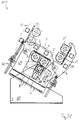
- the calender 100 has a first pivot lever pair 3 and a second pivot lever pair 4.
- Fig. 10 the first pivot lever pair 3 is shown schematically. It can be seen that the swivel lever pair 3 supports the two upper rollers 2, 2 'arranged on both sides on both sides. Fig. 10 also shows that each pivot lever of the pivot lever pair 3 is double-walled.
- the calendar has two similar pairs of pivoting levers 3, 4 and there are exactly two top rollers 2, 2 ', 2 ", 2"' arranged on each of the two pairs of pivot lever.
- Fig. 1 indicates that the pivoting levers 3, 4 are designed as two-armed levers in which on one side of the pivot axis S, S ', the respective top rollers 2, 2', 2 ", 2"'are arranged and on the other side a pivot drive 29th '29' attacks.
- the pivot drive 29, 29 ' comprises a screw jack.
- Each pivot lever is on the pivot axis S, S 'opposite side of a press plane 21, 22 relative to the frame 1 can be fixed.
- Each pivot lever located in working position 9 can be locked on a pivot lever located in parking position 10, in which each pivot lever has a stop surface 11, 11 'pivotally close to its pivot axis S, S' and a stop surface 12, 12 'remote from the pivot axis and the stop surface 11 near the pivot axis , 11 'of the pivot lever located in the parking position 10 rests against the pivot axis remote stop surface 12, 12' of the pivot lever located in the working position 9.
- In the in the FIGS. 1 to 9 shown embodiments is always the left pivot lever in working position. It is understood that the left pivot lever in parking position and the right pivot lever can be in working position.
- Fig. 9 illustrates the pivoting and locking process:
- a first step is a pair of pivot lever (in Fig. 9 the pivot lever pair shown on the right) in a release position 13 can be brought.
- the other pair of pivot levers can be brought into working position.
- the pair of pivot lever from the release position in the park position can be brought, in which its pivot axis near stop surface 11 'on the pivot axis remote abutment surface 12 of the other pair of pivot levers and locks it in this way.
- FIGS. 1 and 9 shows that the parking position 10 of each pivot lever pair is between its release position 13 and its working position 9.
- the calender comprises exactly one lower roller 5 and this is in two different Working positions AU1, AU2 can be brought.
- the lower roller 5 is tiltably arranged to serve the upstream side upper roller 14 or the downstream upper roller 15.
- the lower roller is arranged on a Kipphebelpress 16, the two different end positions 17, 17 ', in each of which a contact surface 18, 18' of the Kipphebelpass rests against a counter-bearing surface 19, 19 'of the frame 1.
- the tilting axis 20 of the rocker arm pair is disposed between the pressing plane 21 of the inlet side nip 8 and the pressing plane 22 of the outlet side nip 8 '(see, for example, FIG Fig. 1 ).
- the movement of the rocker arm pair is about in FIG. 1 , symbolized by the arrow P1.
- the calender comprises exactly two bottom rollers 5, 5 '. These can be delivered independently of each other.
- Each lower roller 5, 5 'shown in the drawings has its own feed device 30, 30', which may comprise a hydraulic cylinder.
- Fig. 5 and 11 the lower roller 5 is shown in two working positions AU1, AU2, one of which is shown in dashed lines.
- the calender 100 comprises a goods feed 23, which comprises a goods transport belt 27.
- this goods conveyor belt 27 is aligned at least substantially horizontally.
- the distance of the goods conveyor belt 27 to the nip 8 ' is relatively large.
- the two top rollers are arranged at the same height in this embodiment.
- the calender 100 is arranged obliquely to make room for the goods conveyor belt 27. As the figure shows, this can be brought closer to the nip 8 ', as by this oblique arrangement, the inlet-side upper roller higher than the outlet-side upper roller is arranged and the inlet-side upper roll thereby provides space for the goods conveyor belt 27.
- the goods conveyor belt 27 is arranged obliquely in the area in front of the nip 8 '. Also in this way it can come closer to the nip, as in the in Fig. 3 shown embodiment. It is a deflection roller 26 is provided which causes a deflection of the goods conveyor belt 27 in the area in front of the nip 8 'upwards.
- the two top rollers are arranged at a height.
- the two top rollers are arranged at two different heights H1, H2.
- the position of the conveyor belt 27 is designed to be variable, depending on whether the inlet-side nip or the outlet-side nip 8 'is realized to be able to come as close as possible to this.
- the goods feeder 23 has an additional transfer belt 24 whose position is changeable.
- Fig. 6 shows a suction roller 25, for transferring the goods on the transfer belt 24th
- the inlet-side lower roller 5 is designed as an alternate lower roller 5a, which can be brought into an evasive position 28.
- the feed device 30 'of this lower roller comprises a telescopic cylinder.
- the conveyor belt or an additional transfer belt can be provided.
- the calender does not comprise any pivot levers with which upper rollers 2, 2 'can be pivoted out of parking positions into working positions. Instead, the top rollers 2, 2 ', as long as they are mounted on the frame 1, always remain in their working position.
- the calender 100 comprises exactly one lower roller 5.
- the calender 100 comprises two lower rollers 5, 5 '.
- the embodiments shown is the lower roller, such as in the in Fig. 1 shown embodiment, arranged on a Kipphebelpress 16, the two different end positions 17, 17 ', on which in each case a contact surface 18, 18' of Kipphebelpass abuts against a counter-bearing surface 19, 19 'of the frame and the pivot axis 20 of Kipphebelpases 16 is between the Pressing plane 21 of the inlet-side nip 8 and the press plane 22 of the outlet-side nip 8 'arranged.
- the lower roller is not pivotable, but slidably disposed to be displaced from the first working position AU1 in the second working position AU2 can.
- it is arranged on a carriage 31 which is displaceable in the direction of the arrow P2.
- the two lower rollers 5, 5 'of in Fig. 13 shown embodiment are deliverable independently. Therefore, as shown in the figure, it is possible to realize two nips 8, 8 'or only the inlet-side nip 8 or only the outlet-side nip 8'.
- the goods conveyor belt 27 at least substantially aligned horizontally and the remaining calender arranged obliquely to make room for this goods conveyor belt 27.
- the two top rollers 2, 2 ' are arranged at a height.
- the inlet-side upper roller 2 creates in the in Fig. 14 shown case in which the outlet-side nip 8 'is realized, space for the goods feed 23, so that the goods conveyor belt 27 as close as possible to the outlet-side nip 8' can reach.
- the two top rollers 2, 2 ' are also arranged at two different heights H1, H2, but with a straight and not obliquely oriented calender, in this respect according to the in FIG Fig. 5 shown embodiment.
- an additional transfer belt 24 is provided which is shown in two different positions and a suction roller 25 transfers the goods from the goods conveyor belt 27 to the transfer belt 24.
- the transfer belt 24 may be coupled to the rocker arm pair 16.
- a guide roller 26 is provided which causes a deflection of the goods conveyor belt 27 in the area in front of the nip 8, 8 'upwards. This is, as with the in Fig. 7 shown embodiment, the inclination of the goods conveyor belt 27 before the nip 8, 8 'changeable without having to change the inclination of the goods conveyor belt before the guide roller 26.
- the inlet-side lower roller 5, as in the in Fig. 8 shown embodiment as a backup roller 5a executed and can pass through an enlarged hub.
- it is equipped with a telescopic cylinder 30a. This allows a deflection, which is greater than the radius of the backup roller 5a.
- the outlet-side nip 8 'space for the goods feed 23 which may include at position 24' the conveyor belt or an additional transfer belt created.
- the calender 100 has exactly one pivot lever pair W, on which two top rollers 2, 2 'are arranged.
- This embodiment has the advantage that later another pair of pivot lever can be retrofitted with additional top rollers.
- the lower roller 5 can be easily removed by swinging the Schwenkhebelpass W, as in the embodiments shown in the FIGS. 11 to 18 are shown, the case is.
- the press planes of the (two) nips run vertically. In the in the FIGS. 4 and 14 and in the Figures 20 and 21 shown embodiments, these press planes are instead inclined. In the in the FIGS. 1 . 3 . 4 . 6 . 7 . 9 . 11 . 14 . 16 . 17 and 19 As shown embodiments, the pivot axis 20 of the Kipphebelbins is centrally located between the inlet-side press plane 21 and the outlet side press plates 22. In the in Fig. 5 In the embodiment shown, the pivot axis 20 is arranged closer to the inlet-side pressing plane 21 than to the outlet-side pressing plane 22.
- the frame 1 is viewed from the side in the in Fig. 1-7 . 9 . 11, 12 . 14 to 17 and 19 shown embodiments formed "U" -shaped.
- the entire frame 1, 101, 10101 is formed stationary.
- the frame 1 has a first stationary frame part OT and a second frame part VT, the second frame part VT being displaceable relative to the first frame part OT.
- the second frame part VT is viewed from the side at least approximately "U" -shaped.
- roller 5 there is exactly one lower roller 5 and this is mounted on the first frame part OT. It is, with the exception of the delivery movement, not relocatable.
- second frame part VT two pairs of pivot lever 3, 4 are mounted, each with two top rollers 2, 2 ', 2 ", 2"'.
- the second frame part VT can be brought into two different positions S1, S2 relative to the first frame part OT, in which the lower roller 5 forms a nip with different top rollers 2, 2 '.
- the second frame part VT is displaceably mounted relative to the first frame part OT by means of a thrust bearing B.
- the thrust bearing B comprises a linear bearing L, thus allowing a straight-line displacement.
- the thrust bearing B includes a carriage and / or rail assembly.
- the thrust bearing B is in the in FIG. 20 shown first position S1 of the second frame part VT completely below the lower roller 5 is arranged. In the in FIG. 21 shown second position S2 of the second frame part VT, it is partially disposed below the lower roller 5.
- the second frame part VT is thus mounted by means of a thrust bearing B slidably on the first frame part OT, which is partially disposed below the lower roller 5, 5 '.
- FIGS. 22 and 23 illustrated as a whole with 10100 designated twenty-first embodiment of the calender according to the invention comprises a frame 101 in which a first roller 102 is arranged.
- the first roller 102 is mounted on a carriage 103, which is displaceable by means of a hydraulically actuated piston / cylinder assembly 104 perpendicular to the longitudinal extent of the roller 101 in the frame, in this case in the vertical direction.
- the piston / cylinder assembly 104 also serves to position the first roller 102 against another roller for nip formation, as will be described below.
- the first roller 102 may be formed as a heated, deflection-controllable roller with a smooth roll shell or in other ways.
- first pivot lever 105 are pivotally mounted about first pivot axes 107.
- the first pivot levers comprise a front, visible in the drawing pivot lever and a distance from this in the direction perpendicular to the plane identical, rear pivot lever, which is not visible in the drawing.
- the following description applies equally to the front, visible first pivot lever 105, as well as the rear pivot lever, although not explicitly mentioned.
- the first pivot levers 105 are designed as two-armed lever.
- a rail arrangement 108 is provided, which serves to attach a second roller 106.
- the second roller 106 is rotatably mounted about its longitudinal axis S2 in a carriage assembly 109 which is displaceable along the rail assembly 108.
- the rail assembly 108 extends along the in FIGS. 22 and 23 shown working position of the first pivot lever each upper edge 1010 and is formed according to the contour of the upper edge as a curved path.
- Linearversteller 1011 The displacement of the carriage assembly 109 along the rail assembly 108 is a Linearversteller 1011, which may be formed as a pneumatically or hydraulically actuated piston / cylinder unit or in any other known manner.
- the one end of the linear adjuster is articulated on the respective first pivot lever 105, the other end on the respective rail arrangement 108.
- a third roller 1012 is mounted rotatably about its longitudinal axis S3 on the carriage arrangement 109.
- the longitudinal axis S3 is spaced from the longitudinal axis S2 by an angular distance ⁇ , which corresponds approximately to the maximum angle a, by which the carriage assembly 109 is displaceable on the rail assembly 108 by means of the linear adjuster 1010.
- pivot drive 1013 which is designed as a screw jack 1014 comprehensive linear drive.
- FIG. 22 an operating state of the calender 10100 is shown in which the first pivot levers 105 are in their working position.
- the second roller 106 as in Figure 22 shown in their working position and forms with the first roller 102 a nip 1015.
- the third roller 1012 is then in its parking position.
- - as in Fig. 23 - The third roller is in its working position and forms with the first roller 102, the nip 1015th Then, the second roller 106 is in its parking position.
- the slide assembly 109 between its in Fig. 22 represented in the first extreme position in which it is based on the graphic representation of the left stop, and their in Fig. 23 shown extreme position in which it is located according to the graphic representation in its right extreme position.
- the first roller can be lowered by means of the piston / cylinder arrangement 104 for the duration of the displacement of the carriage arrangement 109.
- the first pivot lever 105 are - as preferred - briefly raised by means of the rotary actuators 1013.
- the first pivot lever 105 between their in FIGS. 22 and 23 shown working positions in which the upper edges 1016 extend approximately parallel to the lower edge 1017 of the frame 101, and parking positions in which the upper edges 1016 extend approximately perpendicular to the lower edge 1017 to shift.
- these parking positions both the first roller 102, and the second and the third roller from the outside are easily accessible, which is for example for the purpose of replacement or maintenance of great advantage.
- the embodiment of the calender 10100 according to the invention also has second pivot levers 1018, which are mounted on the frame 101 so as to be pivotable about second pivot axes 1019.
- the second pivot lever 1018 are with respect to the plane E, which is defined by the two longitudinal axes of the nip forming rollers, arranged in mirror image to the first pivot lever 105 on the frame 1 and also formed in mirror image to the first pivot lever 105. Accordingly, the second pivot lever 1018 are again designed as a two-armed lever.
- the respective first arm 1018 'of the second pivoting levers 1018 comprises, analogously to the construction of the first pivoting levers 105, a recess with an upper edge 1026 in the working position, which is curved and along which a rail arrangement 1027 extends.
- a slide arrangement 1028 is again provided displaceably along the curved path predetermined by the rail arrangement.
- the shift serves one at each of the second Swivel lever 1018 provided linear adjuster 1029, which in turn may be formed, for example, as a hydraulic or pneumatic piston / cylinder unit or in any other way.
- the carriage arrangement serves to support a fourth roller 1030 and a fifth roller 1031 in a manner corresponding to the bearing of the second roller 106 and third roller 1012.
- the fourth roller 1030 or the fifth roller 1031 can optionally be displaced into their respective parking position and into their respective working position with the aid of the linear adjuster 1029. This is analogous to the second roller 106 and third roller 1012, after the nip has been briefly opened by lowering the first roller 102 or slight pivoting of the second pivot lever 1018.
- the first and second pivot lever 105 pivot axis near locking means 1032 and pivot axis remote locking means 1033 on.
- the locking means are arranged and designed such that the pivot axis near locking of each located in their parking position pivot lever overlap the pivot axis remote locking means 1033 located in their working positions pivot lever and thus acting on the located in their working position swivel bracket reaction forces also on the pivot axes and the linear adjuster of their parking position located pivot lever are introduced into the frame.
- a first roller 10102 is arranged in a frame 10101. It is mounted on a carriage 10103, which by means of a hydraulically actuated piston / cylinder assembly 10104 vertically to the longitudinal extent of the roller 10102 in the frame 10101 is displaceable, in this case in the vertical direction.
- the piston / cylinder arrangement 10104 in turn also serves to set the first roller 10102 against another roller for the purpose of nip formation, as will be described below.
- the first roll 10102 may be formed as a heated, deflection-controllable roll with a smooth roll shell or in some other way.
- first pivot levers 10105 are provided, of which only the front pivot lever facing the viewer can be seen in the drawing.
- the first pivot levers 10105 are for supporting a second roller 10106 and a third roller 10112 at one end thereof, respectively.
- the first pivot levers 10105 are pivotally mounted about a first pivot axis 10107 on the frame 10101, in such a way that it either in one of the in Fig. 24 are located in which either the second roller 10106, or - as in the in Fig. 24 shown in solid line - the third roller 10112 with the first roller 10102 forms a nip 10115 or in a rest position, in which the second and the third roller to the first roller are spaced.
- first pivot lever 10105 are designed as two-armed lever, wherein on the first arm 10105 'the second and third rollers 10106, 10112 are mounted and at the end of the second arm 10105 "a pivot drive 10113 attacks, which in turn is mounted on the frame 10101.
- the pivot drive comprises a screw jack 10114.
- the third roller 10112 is in its working position and forms with the first roller 10102 the nip 10115th
- the first pivot lever are not only with the aid of the pivot drive 10113 about its first pivot axes 10107 pivotally mounted on the frame 10101, but the first pivot axes 10107 are relative to Rack 10101 arranged displaceable.
- the bearing side bearing blocks comprehensive storage facilities 10108 which define the positions of the pivot axes 10107 of the first pivot lever 10105, is provided, the storage facilities 10108 along each rail assembly 10109 by means of linear Verstellers not shown in the drawing are displaced.
- the rail assembly 10109 is oriented upward from the nip 10115 seen.
- the pivot axes 10107 of the first pivot lever 10105 are displaced in a further displacement of the nip 10115 also with a vertical component, whereby the third roller 10112 is displaced during displacement from the working in a parking position with a vertically upward movement component.
- the pivot drive 10113 is synchronously actuated until the first pivot levers 10105, the in Fig. 24 in the left-hand dotted line, in which the third roller 10112 is in a parking position and the second roller 10106 is in a working position in which it forms the nip 10115 with the first roller 10102.
- either the first roller can be lowered by means of the piston / cylinder arrangement 10104 for the duration of the displacement of the pivot axes 10107.
- the 10105 swivel levers are raised briefly with the help of the 10113 quarter-turn actuators.
- a change of in Fig. 25 shown web guide, in particular Relocation of the guide roller 1024 of the web conveying 1025 is then not required.
- the second embodiment of the calender 10200 further comprises to the plane E, which is defined by the longitudinal axes of the two rolls forming the nip 10115 mirrored to the first pivoting levers 10105 and second mirrored to the frame 10101 second pivot lever 10118.
- a fourth roller 10130 and a fifth roller 10131 are mounted on the first arm 10118th.
- the second arm 10118 "is engaged by a second pivot drive 10120 which comprises a second screw jack 10121.
- a separate second pivot drive 10120 is provided for each second pivot lever 10118.
- the respective pivot lever is mounted about a second pivot axis 10119 between the pivot axis Fig. 24 illustrated parking position and working positions, which - mirror images - correspond to those in which the first pivot lever 10105 are shown, pivotable.
- a second bearing device 10127 comprising a bearing block is provided, which in turn can be displaced along a second rail arrangement 10128 with the aid of a linear adjuster, not shown in the drawing. Since the bearing device 10127 defines the second pivot axis 10119, and the second rail assembly 10128 is aligned with the plane E mirror image of the rail assembly 10109, a change between the fourth and the fifth roll can be analogous to the change between the second and the third roller. It is understood that previously the first pivot lever 10105 must be moved to their parking positions, which - again mirrored to the plane E - the in Fig. 24 Park positions represented the second pivot lever 10118 correspond.
- All pivot levers 105, 1018; 10105, 10118 are designed as double-walled lever and engage around a bearing lug of the frame 101, 10101 on both sides.
- a very stable storage of the respective pivot lever is achieved in the frame, which is a tilting of the pivot lever relative to the frame in a direction other than the pivoting movement reliably prevented.
- each pivot lever of a pair rotatably receiving the roller in one of its two end portions.
- the unrecognizable pivot lever of each pivot lever pair have the same configurations as the recognizable pivot lever.
- the same storage facilities and part-turn actuators, rail arrangements and linear adjusters are provided for the unrecognizable swivel lever pairs.
- a to be treated by means of the calender according to the invention web can be passed between the two pivot levers of a pair of pivot levers and it can so in Fig. 25 shown schematically web guide can be realized.
- a web 10W for example in the form of a layer of filaments, between the first roller 102 and one of the second to fifth rollers 106, 1012, 1030, 1031; 10106, 10112, 10130, 10131 formed nip 1015, 10115 supplied and solidified in this.
- suitable cooling rollers 1023 the web is fed in the forward direction V for further use.
- the web guide it is ensured that the web leaves the nip without further contact with the rollers, whereby a thermal damage to the non-solidifying areas is avoided. Also, due to the arrangement of the guide roller 1024 in the immediate vicinity of the nip and with its horizontal tangent above the nip ensured that the unconsolidated goods - fixed on the conveyor belt - can be brought as close to the nip. Finally, the web feed takes place almost parallel to the plane in which the nip is located (nip plane), so that the deflecting roller 1024 is only looped around by a small angle. Due to this measure, the risk of the goods sticking to the screen belt 1022 and tearing is reduced. With the plane in which the nip is located (Nipebene), is referred to in the context of this document in particular the plane perpendicular to the press plane of a nip plane.
- the supply of the bearings with lubricant is to accomplish in a simple manner. Because due to the arrangement of alternatively usable for nip formation second to fifth rolls of pivoting levers, the bearing body only by angle ⁇ 180 °, depending on the design of the pivot lever only by angle ⁇ 150 °, ⁇ 120 ° or even ⁇ 90 ° at a shift between working - and parking position twisted. This is a great advantage, in particular in the case of bearing lubrication without contacting seals and, consequently, pressureless, gravity-only oil drainage, as conventionally used in heated rolls. Bearing lubricating oil drains and return lines with gravity feed are thus easily executable.
- rollers are rotatably drivable in their parking position. Because especially at elevated roller temperatures, especially at roller temperatures> 80 ° C, the rollers must be rotated continuously to avoid permanent deformation.
- all rollers, at least the second to fifth rollers can be provided with their own rotary drives, which are not recognizable in the drawing. Its own rotary drives also make any otherwise necessary coupling and uncoupling of a common rotary drive unnecessary. So that separate drive blocks for the own rotary drives with the rollers do not have to be moved, it is advantageous if the own rotary actuators are designed as "direct drives".
- first and second pivoting lever with the associated second and third and fourth and fifth rollers have first and second pivoting lever with the associated second and third and fourth and fifth rollers. According to the invention, however, are also embodiments in which only the first pivot lever with the second and third rollers are present, especially if these embodiments are suitable to be supplemented with second pivot lever with fourth and fifth rollers.
Landscapes
- Engineering & Computer Science (AREA)
- Textile Engineering (AREA)
- Casting Or Compression Moulding Of Plastics Or The Like (AREA)
- Treatment Of Fiber Materials (AREA)
- Paper (AREA)
Abstract
1. Kalander (100) mit einem Gestell (1), in dem mehrere Oberwalzen (2, 2', 2", 2"') und mindestens eine Unterwalze (5, 5') gelagert sind, wobei die Unterwalze (5, 5') mit einer Oberwalze (2, 2', 2", 2"') einen Nip (8) bilden kann.A calender (100) having a frame (1) in which a plurality of upper rollers (2, 2 ', 2 ", 2"') and at least one lower roller (5, 5 ') are mounted, wherein the lower roller (5, 5 ') with a top roller (2, 2', 2 ", 2" ') can form a nip (8).
Description
Die Erfindung betrifft einen Kalander, mit einem Gestell, in dem mehrere Oberwalzen und mindestens eine Unterwalze gelagert sind.The invention relates to a calender, with a frame in which a plurality of upper rollers and at least one lower roller are mounted.
Bei Kalandern, insbesondere solchen zur Behandlung von Vlies-, Textil-, Kunststoff- oder Papier-Warenbahnen, besteht häufig die Notwendigkeit, eine der beiden Walzen eines Nips auszutauschen. Meist soll dies zum Austausch der Oberflächenqualität (Gravur, Belag, Härte) erfolgen.In calenders, especially those for the treatment of nonwoven, textile, plastic or paper webs, there is often the need to exchange one of the two rolls of a nip. This is usually done to replace the surface quality (engraving, coating, hardness).
Ein Austausch einer Walze ist gerade bei einfachen Kalandern oft aufwendig. Zahlreiche manuelle Arbeiten sind notwendig. Erwähnt seien der Antrieb, die Lagerschmierung, ggf. die Heizung und natürlich die Abstützung der Walze. Ist die Walze beheizt, so muss die auszutauschende Walze zunächst zeitaufwendig abgekühlt und die neue Walze vor Produktionsbeginn aufgeheizt werden. Lange Anlagenstillstands- und Produktionsausfallzeiten sind die Folge. Für den schnellen Walzenwechsel vorgesehene Kalandertypen sind oft aufwendig oder erfordern einen vergrößerten Walzendurchmesser. In einigen Varianten steht nur eine Alternativwalze für eine der beiden bzw. für beide Walzen eines Nips zur Verfügung. Einige Schnellwechselkalander sind nicht für bestimmte Anwendungsarten, etwa das Kalandrieren von Vlies, geeignet.Replacing a roller is often expensive, especially for simple calenders. Numerous manual work is necessary. Mention should be the drive, the bearing lubrication, possibly the heater and of course the support of the roller. If the roller is heated, the roller to be replaced must first be time-consuming cooled and the new roller to be heated before starting production. Long downtimes and production downtimes are the result. For the fast roll change provided calender types are often expensive or require an enlarged roll diameter. In some variants, only one alternative roller is available for one or both of a nip roll. Some quick-change calenders are not suitable for certain types of applications, such as calendering fleece.
Die Erfindung hat es sich zur Aufgabe gemacht, einen Kalander zu schaffen, bei dem zumindest eine Walze eines Nips schnell ausgetauscht werden kann und der hinsichtlich zumindest eines der genannten Nachteile verbessert ist.The invention has set itself the task of creating a calender in which at least one roller of a nip can be exchanged quickly and which is improved in terms of at least one of the disadvantages mentioned.
Diese Aufgabe wird durch den in Anspruch 1 wiedergegebenen Kalander gelöst.This object is achieved by the recited in
Der erfindungsgemäße Kalander weist ein Gestell auf, in dem mehrere Oberwalzen und mindestens eine Unterwalze gelagert sind. Die mindestens eine Unterwalze kann mit einer Oberwalze einen Nip bilden.The calender according to the invention has a frame in which a plurality of top rollers and at least one bottom roller are mounted. The at least one lower roller can form a nip with a top roller.
Bevorzugt ist durch den Kalander ein einlaufseitiger Nip und ein auslaufseitiger Nip bereitstellbar. In einer Ausführungsform ist durch den Kalander gleichzeitig ein einlaufseitiger und ein auslaufseitiger Nip bereitstellbar. In einer anderen Ausführungsform ist durch den Kalander zu einem Zeitpunkt lediglich ein einlaufseitiger oder ein auslaufseitiger Nip bereitstellbar.Preferably, an inlet-side nip and an outlet-side nip can be provided by the calender. In one embodiment, an inlet side and an outlet side nip can be provided by the calender at the same time. In another embodiment, only one inlet-side or one outlet-side nip can be provided by the calender at a time.
Mindestens eine Unterwalze ist bevorzugt mit einer eigenen Zustelleinrichtung versehen, mit der sie bevorzugt auf eine Oberwalze zu- und von dieser wegbewegbar ist, besonders bevorzugt translatorisch. Die Zustelleinrichtung kann einen Hydraulikzylinder umfassen. Die Begriffe "Zustelleinrichtung" und "Zustellvorrichtung" sind im Rahmen dieser Druckschrift synonym.At least one lower roller is preferably provided with its own feed device, with which it can preferably be moved toward and away from an upper roller, particularly preferably translationally. The delivery device may comprise a hydraulic cylinder. The terms "delivery device" and "delivery device" are synonymous in the context of this document.
In einer wichtigen Ausführungsform dient der Kalander dem thermischen Verfestigen von Vliesstoffen. Es kann eine glatte Walze gegen eine gravierte Walze wirken. Auch können beide Walzen eines Nips graviert sein. Mindestens eine der beiden Walzen eines Nips kann beheizt sein. Um verschiedene Produkte zu erzeugen, ist bevorzugt die gravierte Walze schnell austauschbar. In einer Ausführungsform ist nur die Oberwalze eines Nips graviert.In an important embodiment, the calender serves to thermally strengthen nonwoven fabrics. It can act as a smooth roller against an engraved roller. Also, both rolls of a nips can be engraved. At least one of the two rolls of a nip can be heated. In order to produce different products, preferably the engraved roll is quickly exchangeable. In one embodiment, only the top roll of a nip is engraved.
In einer anderen Ausführungsform dient der Kalander dem Kalandrieren von Papier oder Textil.In another embodiment, the calender is used for calendering paper or textile.
In einer Ausführungsform wirkt eine Walze mit einem Belag gegen eine beheizte glatte oder auch gravierte Walze. Mit dem Begriff "Belag" sind im Rahmen dieser Druckschrift zum einen insbesondere Walzen gemeint, die eine nachgiebige Beschichtung aufweisen und zum anderen insbesondere, in einer weiten Verwendung dieses Begriffs, auch Baumwollwalzen. Auch hier kann ein schneller Austausch der Gravur gewünscht sein. Häufiger besteht aber der Bedarf, den Belag auszutauschen, um eine andere Belagsart oder -härte zum Einsatz zu bringen, oder auch diesen nachschleifen zu können, da Verschleiß vor allem an dem weicheren Belag stattfindet.In one embodiment, a roller with a coating acts against a heated smooth or even engraved roller. With the term "covering" are in the context of this Reference document on the one hand meant in particular rollers which have a resilient coating and on the other hand, in particular, in a wide use of this term, also cotton rollers. Again, a quick exchange of the engraving may be desired. More often, however, there is a need to replace the pad to bring a different type or coating hardness used or regrind this, since wear takes place mainly on the softer pad.
Mit Vorteil kann durch den Walzenwechsel eine schnelle Temperaturänderung der Walzenoberfläche zumindest einer Walze eines Nips herbeigeführt werden. Dies geschieht bevorzugt ohne einen Temperaturwechsel in einer Walze von 1 bis 10 K/min zu überschreiten, da andernfalls Thermospannungen im Walzenmaterial zu befürchten sind.Advantageously, a rapid temperature change of the roll surface of at least one roll of a nip can be brought about by the roll change. This is preferably done without exceeding a temperature change in a roll of 1 to 10 K / min, since otherwise thermoelectric stresses in the roll material are to be feared.
Mit Vorteil ermöglicht der Kalander ein schnelles Austauschen einer Walze, ohne manuelles Eingreifen.Advantageously, the calender allows a quick replacement of a roller, without manual intervention.
Bevorzugt ist ein Walzentausch in kürzerer Zeit als das Auf- oder Abheizen der Walze möglich.Preferably, a roller exchange in a shorter time than the heating or heating of the roller is possible.
In einer Ausführungsform ist mindestens eine Unterwalze vorgesehen, die in zwei verschiedene Arbeitspositionen bringbar ist und die weiter bevorzugt mit verschiedenen Oberwalzen einen Nip bildet. Es sind also bevorzugt mindestens zwei verschiedene Unterwalzenpositionen vorgesehen, von denen zu einem Zeitpunkt bevorzugt lediglich eine ausgewählt ist. Genau eine Unterwalze kann vorzugsweise also; in einer Ausführungsform lediglich nacheinander; zwei verschiedene Nips bilden, deren Position bevorzugt voneinander abweicht.In one embodiment, at least one lower roller is provided, which can be brought into two different working positions and more preferably forms a nip with different upper rollers. Thus, at least two different lower roller positions are preferably provided, of which only one is preferably selected at a time. Exactly one lower roller can therefore preferably; in one embodiment only sequentially; form two different nips whose position preferably differs from each other.
In einer Ausführungsform ist die Unterwalze verkippbar und/oder verschiebbar vorgesehen, vorzugsweise um die einlaufseitige Oberwalze oder die auslaufseitige Oberwalze oder auch zwei Oberwalzen gleichzeitig zu bedienen.In one embodiment, the lower roller is provided tiltable and / or displaceable, preferably to serve the upstream side upper roller or the outlet side upper roller or two upper rollers simultaneously.
Mit dem Begriff "einlaufseitig" ist im Rahmen dieser Druckschrift insbesondere die Seite des Kalanders bezeichnet, an der die Ware in den Kalander einläuft. Mit dem Begriff "auslaufseitig" ist im Rahmen dieser Druckschrift insbesondere die Seite des Kalanders bezeichnet, an der die Ware den Kalander verlässt.The term "inlet side" is in the context of this document in particular the side of the calender designates, at which the goods enters the calender. With The term "outlet side" is in the context of this document in particular the side of the calender designation, at which the goods leave the calender.
Bevorzugt ist eine Unterwalze des Kalanders an einem Kipphebelpaar angeordnet. Die beiden Kipphebel dieses Kipphebelpaares sind bevorzugt lediglich paarweise verkippbar. Dieses Kipphebelpaar weist bevorzugt zwei verschiedene Endpositionen auf, in denen weiter bevorzugt jeweils eine Anlagefläche des Kipphebelpaares an einer Gegenanlagefläche des Gestells anliegt. Hierdurch sind auf einfach Art und Weise zwei verschiedene, definierte Positionen des Kipphebelpaares und damit zwei verschiedene definierte Positionen der Unterwalze geschaffen.Preferably, a lower roller of the calender is arranged on a pair of rocker arms. The two rocker arms of this rocker arm pair are preferably only tiltable in pairs. This rocker arm pair preferably has two different end positions, in which, in each case, a contact surface of the pair of rocker arms more preferably bears against a counter-bearing surface of the frame. As a result, two different, defined positions of the Kipphebelpaares and thus two different defined positions of the lower roller are created in a simple manner.
Die Kippachse des Kipphebelpaares liegt bevorzugt zwischen der Pressebene des einlaufseitigen Nips und der Pressebene des auslaufseitigen Nips. Hierdurch ergibt sich eine Aufteilung der von der Unterwalze auf das Kipphebelpaar übertragenen Kraft mit einer Kraftkomponente in Längsrichtung der Kipphebel und einer Kraftkomponente, die das Kipphebelpaar gegen den jeweiligen Anschlag presst und zu einer Art Verriegelung der Position des Kipphebelpaares führt.The tilting axis of the rocker arm pair is preferably located between the press plane of the inlet-side nip and the press plane of the outlet-side nip. This results in a division of the transmitted from the lower roller on the Kipphebelpaar force with a force component in the longitudinal direction of the rocker arm and a force component that presses the Kipphebelpaar against the respective stop and leads to a kind of locking the position of Kipphebelpaares.
Bevorzugt entsprechen die beiden Endpositionen, die die Unterwalze in den beiden Endpositionen des Kipphebelpaares einnimmt, den beiden Arbeitspositionen der Unterwalze, in denen diese vorzugsweise mit der zugehörigen Oberwalze einen Nip bildet.Preferably, the two end positions, which occupies the lower roller in the two end positions of the Kipphebelpaares, the two working positions of the lower roller, in which this preferably forms a nip with the associated upper roller.
In einer Ausführung umfasst der Kalander genau eine Unterwalze.In one embodiment, the calender comprises exactly one lower roller.
In einer anderen Ausführungsform umfasst der Kalander mehr als eine Unterwalze.In another embodiment, the calender comprises more than one lower roll.
In einer Ausführungsform ist mehr als eine weitere Walze eines Nips zum Austausch bereitgehalten.In one embodiment, more than one additional roll of a nip is kept ready for replacement.
In einer Ausführungsform umfasst der Kalander genau zwei Unterwalzen, die weiter bevorzugt unabhängig voneinander zustellbar sind.In one embodiment, the calender comprises exactly two lower rolls, which are more preferably deliverable independently of one another.
Die Zustellbewegung der Unterwalzen erfolgt bevorzugt translatorisch, vorzugsweise ausschließlich.The feed movement of the lower rollers is preferably translational, preferably exclusively.
In einer Ausführungsform ist mindestens eine Unterwalze des Kalanders - mit Ausnahme der Zustellbewegung - nicht verlagerbar.In one embodiment, at least one lower roller of the calender - with the exception of the feed movement - not displaced.
Bei mehreren Unterwalzen kann, wie bevorzugt, auch die Temperatur oder die Oberflächenqualität der Unterwalze schnell verändert werden. Hierdurch ist es, wie in einer Ausführungsform, zudem möglich, durch mehrere, etwa zwei, Walzenspalte zu fahren.With several lower rollers, as preferred, the temperature or the surface quality of the lower roller can be changed quickly. As a result, as in one embodiment, it is also possible to drive through a plurality, for example two, nips.
Das Gestell kann von der Seite betrachtet zumindest in etwa "U"-förmig ausgebildet sein.The frame can be viewed from the side formed at least approximately "U" -shaped.
Die lichte Weite des "U"-förmigen Gestells oder Gestellteils kann größer sein, als der doppelte Durchmesser der Unterwalze.The clear width of the "U" -shaped frame or frame part can be greater than twice the diameter of the lower roller.
In einer Ausführungsform ist das gesamte Gestell ortsfest ausgebildet.In one embodiment, the entire frame is formed stationary.
In einer anderen Ausführungsform weist das Gestell ein erstes ortsfestes Gestellteil und ein zweites Gestellteil auf, wobei das zweite Gestellteil verlagerbar zu dem ersten Gestellteil vorgesehen ist. In dieser Ausführungsform kann das zweite Gestellteil von der Seite betrachtet zumindest in etwa "U"-förmig ausgebildet sein. Die Warenzuführung und das Warentransportband können in dieser Ausführungsform immer in der gleichen Position verbleiben. Die Position der Warenzuführung und des Warentransportbandes kann also unveränderbar ausgestaltet sein. Wie auch in anderen Ausführungsformen können die Nips geneigt sein, sodass die Ware den Nip ohne weitere Berührung der Walzenoberflächen verlassen kann.In another embodiment, the frame has a first stationary frame part and a second frame part, wherein the second frame part is provided so as to be displaceable relative to the first frame part. In this embodiment, the second frame part viewed from the side may be formed at least approximately "U" -shaped. The goods feeder and the goods conveyor belt can always remain in the same position in this embodiment. The position of the goods feed and the goods conveyor belt can therefore be designed unchangeable. As in other embodiments, the nips may be inclined so that the fabric may leave the nip without further contact with the roll surfaces.
Bevorzugt ist mindestens eine - bevorzugt genau eine - Unterwalze an dem ersten Gestellteil gelagert und weiter bevorzugt ist mindestens eine Oberwalze - bevorzugt alle Oberwalzen - an dem zweiten Gestellteil gelagert. Die mindestens eine Oberwalze ist dabei bevorzugt nicht unmittelbar an dem zweiten Gestellteil gelagert.Preferably, at least one - preferably exactly one - lower roller is mounted on the first frame part and more preferably at least one upper roller - preferably all upper rollers - mounted on the second frame part. The At least one top roller is preferably not mounted directly on the second frame part.
Das zweite Gestellteil ist bevorzugt an dem ersten Gestellteil gelagert, vorzugsweise verschiebbar und/oder verkippbar.The second frame part is preferably mounted on the first frame part, preferably displaceable and / or tiltable.
Bevorzugt ist das zweite Gestellteil relativ zu dem ersten Gestellteil mittels eines Schublagers verschiebbar gelagert. Das Schublager kann ein Linearlager umfassen, also eine geradlinige Verschiebung zulassen. Auch eine Lagerung, die eine Verschiebbarkeit entlang einer gekrümmten Linie zulässt, ist grundsätzlich denkbar. Bevorzugt umfasst das Schublager eine Schlitten und/oder Schienenanordnung.Preferably, the second frame part is displaceably mounted relative to the first frame part by means of a thrust bearing. The thrust bearing may comprise a linear bearing, so allow a linear displacement. Also, a storage that allows a displacement along a curved line is conceivable in principle. The thrust bearing preferably comprises a carriage and / or rail arrangement.
Das Schublager ist bevorzugt teilweise oder ganz unterhalb der Unterwalze angeordnet.The thrust bearing is preferably arranged partially or completely below the lower roller.
In der grundsätzlich denkbaren Ausführungsform, in der das zweite Gestellteil verkippbar an dem ersten Gestellteil gelagert ist, ist das Kipplager bevorzugt unterhalb der Unterwalze angeordnet.In the basically conceivable embodiment, in which the second frame part is tiltably mounted on the first frame part, the tilting bearing is preferably arranged below the lower roller.
Das zweite Gestellteil ist vorzugsweise in - bevorzugt zwei - verschiedene Positionen relativ zu dem ersten Gestellteil bringbar, in denen eine Unterwalze mit verschiedenen Oberwalzen einen Nip bildet.The second frame part is preferably in - preferably two - different positions can be brought relative to the first frame part, in which a lower roller with different top rollers forms a nip.
In einer Ausführungsform weist der Kalender zumindest ein Walzenlagerungsschwenkhebelpaar auf - in einer Ausführungsform genau ein Walzenlagerungsschwenkhebelpaar - an dem mindestens eine Oberwalze - in einer Ausführungsform genau eine Oberwalze - angeordnet ist. Ein derartiges Walzenlagerungsschwenkhebelpaar wird im Rahmen dieser Druckschrift auch kurz als Schwenkhebelpaar bezeichnet und ein Walzenlagerungsschwenkhebel eines derartigen Paares wird im Rahmen dieser Druckschrift auch kurz als Schwenkhebel bezeichnet. Die Schwenkhebel eines Schwenkhebelpaares sind bevorzugt lediglich paarweise verschwenkbar. Mit diesem mindestens einen Schwenkhebelpaar ist bevorzugt mindestens eine Oberwalze aus einer Parkposition in eine Arbeitsposition verschwenkbar. Das mindestens eine Schwenkhebelpaar ist bevorzugt in eine Arbeitsposition schwenkbar, in der die an ihm angeordnete mindestens eine Walze in einer Arbeitsposition ist. Das mindestens eine Schwenkhebelpaar ist zudem bevorzugt in eine Parkposition schwenkbar, in der die mindestens eine an ihm angeordnete Walze in einer Parkposition ist. Als "Arbeitsposition" einer Walze wird im Rahmen dieser Druckschrift insbesondere die Position einer Walze bezeichnet, in der diese mit einer Gegenwalze einen Nip bildet oder bilden kann.In one embodiment, the calendar has at least one Walzenlagerungsschwenkhebelpaar - in one embodiment exactly a Walzenlagerungsschwenkhebelpaar - on the at least one upper roller - in one embodiment exactly one upper roller - is arranged. Such Walzenlagerungsschwenkhebelpaar is referred to in the context of this document also briefly as Schwenkhebelpaar and a Walzenlagerungsschwenkhebel of such a pair is also referred to as a pivoting lever in the context of this document. The pivot lever of a pivot lever pair are preferably only in pairs pivotable. With this at least one pivot lever pair is preferably at least one upper roller of a Parking position pivoted into a working position. The at least one pivot lever pair is preferably pivotable into a working position, in which the at least one roller arranged on it is in a working position. The at least one pair of pivot levers is also preferably pivotable into a parking position, in which the at least one roller arranged on it is in a parking position. As a "working position" of a roller is in the context of this document, in particular the position of a roller referred to, in which it forms or forms a nip with a counter-roller.
Mit Vorteil ist das mindestens eine Schwenkhebelpaar um etwa 90° verschwenkbar.Advantageously, the at least one pivot lever pair can be pivoted by approximately 90 °.
In einer wichtigen Ausführungsform weist der Kalander ein erstes Schwenkhebelpaar und ein zweites Schwenkhebelpaar auf.In an important embodiment, the calender has a first pair of pivot levers and a second pair of pivot levers.
Mit Vorteil ist jedes Schwenkhebelpaar um eine Schwenkachse verschwenkbar am Gestell gelagert.Advantageously, each pivot lever pair is mounted pivotably about a pivot axis on the frame.
Jedes Schwenkhebelpaar stellt bevorzugt eine Lagerung für eine Walze bereit. Die an dem mindestens einen Schwenkhebelpaar angeordneten Walzen sind also über das Schwenkhebelpaar am Gestell des Kalanders gelagert.Each pivot lever pair preferably provides a support for a roller. The rollers arranged on the at least one pair of pivot levers are thus mounted on the frame of the calender via the pivot lever pair.
Die Versorgung der Lager der an dem mindestens einen Schwenkhebelpaar angeordneten Oberwalzen ist einfach zu lösen. Denn die Lagerkörper werden bevorzugt nur um einen Winkel von etwa 90° verdreht. Mit Vorteil ist eine Lagerschmierung ohne berührende Dichtungen und folglich drucklosem, nur der Schwerkraft folgendem Ölablauf realisiert. Da die Lagerkörper bevorzugt nur um einen Winkel von etwa 90° verdreht werden, sind die Lagerschmier-Ölabläufe und Lagerschmier-Ölrücklaufleitungen mit Schwerkraftförderung einfach ausführbar.The supply of the bearings of the at least one pair of pivot lever arranged upper rollers is easy to solve. Because the bearing body are preferably only rotated by an angle of about 90 °. Advantageously, a bearing lubrication is realized without contacting seals and consequently unpressurized, following only the gravity oil drain. Since the bearing bodies are preferably rotated only by an angle of about 90 °, the bearing lubricating oil drains and bearing lubricating oil return lines with gravity feed are easy to carry out.
Bevorzugt sind an dem ersten Schwenkhebelpaar und/oder dem zweiten Schwenkhebelpaar mindestens zwei Oberwalzen gelagert.Preferably, at least two top rollers are mounted on the first pair of pivot levers and / or the second pair of pivot levers.
In einer Ausführungsform sind sowohl an dem ersten Schwenkhebelpaar, als auch an dem zweiten Schwenkhebelpaar jeweils mindestens zwei Oberwalzen gelagert.In one embodiment, at least two upper rollers are mounted both on the first pivot lever pair, and on the second pair of pivot levers.
Die Parkposition jeder Oberwalze ist bevorzugt so weit von der Unterwalze entfernt, dass eine Bewegung der mindestens einen an dem anderen Schwenkhebelpaar angeordneten Walze aus der Arbeitsposition in die Parkposition und umgekehrt möglich ist.The parking position of each upper roller is preferably so far away from the lower roller, that a movement of the at least one arranged on the other pair of pivot lever roller from the working position in the parking position and vice versa is possible.
Bevorzugt stimmen die Arbeitspositionen von mindestens zwei verschiedenen Oberwalzen überein.Preferably, the working positions of at least two different top rollers match.
Die Oberwalzen sind bevorzugt jeweils gemeinsam mit ihrer Antriebs- und ggf. Versorgungseinrichtung verlagerbar.The upper rollers are preferably displaceable together with their drive and possibly supply device.
In einer Ausführungsform entspricht die Zahl der Unterwalzen die Zahl der in einem Schwenkhebel gelagerten Oberwalzen.In one embodiment, the number of bottom rollers corresponds to the number of top rollers mounted in a pivoting lever.
In der Ausführungsform, in der das Gestell ein erstes ortsfestes Gestellteil und ein zweites Gestellteil aufweist, wobei das zweite Gestellteil verlagerbar zu dem ersten Gestellteil vorgesehen ist, ist das Schwenkhebelpaar vorzugsweise an dem zweiten Gestellteil gelagert. In der Ausführungsform mit zwei Schwenkhebelpaaren sind bevorzugt beide Schwenkhebelpaare an dem zweiten Gestellteil gelagert. Die mindestens eine Oberwalze ist also bevorzugt mittels mindestens eines Schwenkhebelpaares an dem zweiten Gestellteil gelagert. Bei einer Verschiebung des zweiten Gestellteils werden bevorzugt die Schwenkhebel mitsamt ihren Lagern, Schwenkachsen, Schwenkantrieben und den an ihnen gelagerten Oberwalzen mitverschoben.In the embodiment in which the frame has a first stationary frame part and a second frame part, wherein the second frame part is provided displaceable to the first frame part, the pivot lever pair is preferably mounted on the second frame part. In the embodiment with two swivel lever pairs, both swivel lever pairs are preferably mounted on the second frame part. The at least one top roller is thus preferably mounted by means of at least one pair of pivot levers on the second frame part. During a displacement of the second frame part, preferably the pivot levers together with their bearings, pivot axes, swivel drives and the upper rollers mounted on them are also displaced.
Um die im Kalandergestell wirkenden Kräfte zu reduzieren, ist mit Vorteil jeder Schwenkhebel auf der seiner Schwenkachse gegenüberliegenden Seite einer Pressebene eines Nips arretierbar. Dies ist bevorzugt derart realisiert, dass der gegenüberliegende Schwenkhebel zunächst über die Parkposition hinaus schwenkbar ist, anschließend der Schwenkhebel in die Arbeitsposition bringbar ist und der gegenüberliegende Schwenkhebel in seine Parkposition zurück verlagerbar ist und hierdurch den Schwenkhebel arretiert. Weiter bevorzugt erfolgt die Arretierung dadurch, dass jeder Schwenkhebel eine schwenkachsennahe Anschlagfläche und eine schwenkachsenferne Anschlagfläche aufweist und die schwenkachsennahe Anschlagfläche des Schwenkhebels in seiner Parkposition mit Vorteil an der schwenkachsenfernen Anschlagfläche eine sich in Arbeitsposition befindlichen Schwenkhebels anliegt. Mit anderen Worten ist jeder in Arbeitsposition befindliche Schwenkhebel bevorzugt an einem in Parkposition befindlichen Schwenkhebel verriegelbar.In order to reduce the forces acting in the calender frame, each pivot lever can advantageously be locked on the side of a press plane of a nip opposite its pivot axis. This is preferably realized such that the opposite pivot lever is initially pivotable beyond the park position, then the pivot lever can be brought into the working position and the opposite pivot lever back to its parking position is displaced and thereby locks the pivot lever. More preferably, the locking takes place in that each pivot lever has a pivot axis near stop surface and a pivot axis remote stop surface and the pivot axis near stop surface of the pivot lever in its parking position with advantage on the pivot axis remote stop surface is located in a working position pivot lever. In other words, each pivoting lever located in the working position is preferably lockable on a pivoting lever located in parking position.
Mit Vorteil ist jeder Schwenkhebel in eine Freigabeposition bringbar. Die Parkposition jedes Schwenkhebels liegt bevorzugt zwischen seiner Freigabeposition und seiner Arbeitsposition. Mit Vorteil ist jeder Schwenkhebel in seiner Freigabeposition gerade so weit geneigt, dass der andere Schwenkhebel kollisionsfrei gegen dem ersten Schwenkhebel in seine Parkposition gebracht werden kann.Advantageously, each pivot lever can be brought into a release position. The parking position of each pivot lever is preferably between its release position and its working position. Advantageously, each pivot lever in its release position is just so far inclined that the other pivot lever can be brought collision-free against the first pivot lever in its parking position.
Mit Vorteil sind die Schwenkhebel als zweiarmige Hebel ausgebildet, bei denen auf einer Seite der Schwenkachse mindestens eine Oberwalze angeordnet ist und auf der anderen Seite bevorzugt ein Schwenkantrieb angreift.Advantageously, the pivot lever are designed as two-armed lever in which on one side of the pivot axis at least one upper roller is arranged and on the other side preferably engages a pivot drive.
Jeder Schwenkhebel ist bevorzugt doppelwandig ausgebildet und umgreift weiter bevorzugt eine Lagerlasche des Gestells beidseitig.Each pivot lever is preferably double-walled and further preferably surrounds a bearing lug of the frame on both sides.
Mit Vorteil sind die Oberwalzen lösbar an den Schwenkhebeln befestigt.Advantageously, the upper rollers are releasably attached to the pivot levers.
Die Oberwalzen können graviert sein. Die Oberwalzen können jedoch auch glatt sein. Auch die mindestens eine Unterwalze kann graviert oder glatt sein. Alle oder einzelne Walzen können durchbiegesteuerbar sein. Der Kalander kann sowohl konventionelle Walzen für kleine Linienkräfte, als auch durchbiegesteuerbare Walzen für höhere Kräfte oder höhere Genauigkeiten aufweisen. Mit Vorteil ist ein Aufheizen und ein Abkühlen der Walzen in ihrer Parkposition möglich.The top rollers can be engraved. However, the top rollers can also be smooth. Also, the at least one lower roller can be engraved or smooth. All or individual rolls can be flexurally controllable. The calender can have both conventional small line force rolls and flexurally controllable rolls for higher forces or higher accuracies. Advantageously, a heating and cooling of the rollers in their parking position is possible.
Zur Vereinfachung des Antriebs können einzelne oder alle Walzen des Kalanders mit einem Direktantrieb ausgestattet sein.To simplify the drive, individual or all of the rollers of the calender can be equipped with a direct drive.
In einer Ausführungsform sind die Arbeitspositionen aller Oberwalzen auf einer Höhe angeordnet.In one embodiment, the working positions of all top rollers are arranged at a height.
In einer Ausführungsform ist der Kalander für Vlieswaren vorgesehen. Genauer gesagt dient der Kalander in dieser Ausführungsform zur thermischen Verfestigung von Vliesstoffen. Bevorzugt wird das Vlies erst unmittelbar vor der Verfestigung im Kalander auf ein Warentransportband einer Warenzuführung abgelegt und gebildet. Die Warenzuführung reicht bevorzugt bis weniger als 10 cm oder 5 cm an die den Nip bildenden Walzen heran.In one embodiment, the calender is intended for nonwoven goods. More specifically, in this embodiment, the calender serves to thermally solidify nonwoven fabrics. Preferably, the web is deposited and formed on a goods conveyor belt of a goods feed only immediately prior to solidification in the calender. The goods feed is preferably up to less than 10 cm or 5 cm approach the nip forming rollers.
Bevorzugt weist der Kalander eine Warenzuführung auf, die weiter bevorzugt ein Warentransportband umfasst, und die Warenzuführung ist bevorzugt als Vlieszuführung ausgeführt.Preferably, the calender has a goods feed, which more preferably comprises a goods conveyor belt, and the goods feed is preferably carried out as a nonwoven feed.
Das Warentransportband dient bevorzugt also dem Transport der Warenbahn.The goods conveyor belt is therefore preferably used to transport the web.
Mit Vorteil ist das Warentransportband zumindest im Wesentlichen horizontal ausgerichtet. Der übrige Kalander ist in einer Ausführungsform schräg angeordnet, um Platz für dieses Warentransportband - insbesondere dann, wenn der auslaufseitige Nip aktiv ist - zu schaffen. Die Nips können also geneigt sein. In der Ausführungsform, in der der übrige Kalander schräg angeordnet ist, ist er bevorzugt in Warentransportrichtung leicht nach unten geneigt.Advantageously, the goods conveyor belt is aligned at least substantially horizontally. The remainder of the calender is skewed in one embodiment to make room for this fabric conveyor, particularly when the downstream nip is active. The nips can be so inclined. In the embodiment in which the remaining calender is arranged obliquely, it is preferably inclined slightly downwards in the goods transport direction.
Mit dem Begriff "Warenzuführung" wird im Rahmen dieser Druckschrift insbesondere eine Vorrichtung bezeichnet, die zu kalandrierende Waren, bevorzugt Vlies, bis unmittelbar vor den Nip transportiert.In the context of this publication, the term "goods feed" refers in particular to a device which transports goods to be calendered, preferably fleece, until immediately before the nip.
Die Warenzuführung kann ein Siebband umfassen, mit einer Siebbandumlenkwalze die möglichst nahe an dem jeweiligen Nip angeordnet ist.The goods feed may comprise a screen belt, with a Siebbandumlenkwalze as close as possible to the respective nip is arranged.
In einer Ausführungsform ist das Warentransportband in dem Bereich vor dem jeweiligen Nip schräg angeordnet, bevorzugt in Warentransportrichtung schräg nach oben. Auf diese Weise kann das Warentransportband - insbesondere dann, wenn es den auslaufseitigen Nip bedient - näher an den Nip heran reichen.In one embodiment, the goods conveyor belt is arranged obliquely in the region in front of the respective nip, preferably obliquely in the goods transport direction up. In this way, the goods conveyor belt - especially when it operates the outlet side nip - reach closer to the nip zoom.
Insbesondere in der Ausführungsform, in der der Kalander ein in dem Bereich vor dem Nip zumindest im Wesentlichen horizontales Warentransportband umfasst, können die Oberwalzen Arbeitspositionen aufweisen, die in verschiedenen Höhen vorgesehen sind. Bevorzugt ist die Arbeitsposition der auslaufseitigen Oberwalze niedriger vorgesehen, als die Arbeitsposition der einlaufseitigen Oberwalze. Auf diese Weise schafft die einlaufseitige Oberwalze, wenn der auslaufseitige Nip realisiert ist, Platz für das Warentransportband. In der Ausführungsform, in der die Oberwalzen Arbeitspositionen aufweisen, die in verschiedenen Höhen vorgesehen sind, sind die Oberwalzen also bevorzugt höhenversetzt an dem jeweiligen Schwenkhebelpaar angeordnet. In einer anderen Ausführungsform, in der die Oberwalzen Arbeitspositionen aufweisen, die in verschiedenen Höhen vorgesehen sind, ist dies bevorzugt durch Schrägstellung des Kalanders bewirkt.In particular, in the embodiment in which the calender comprises a product conveyor belt which is at least substantially horizontal in the region in front of the nip, the top rollers may have working positions which are provided at different heights. Preferably, the working position of the outlet side upper roller is provided lower than the working position of the upstream side upper roller. In this way, the inlet-side upper roller, if the outlet-side nip is realized, creates space for the goods conveyor belt. In the embodiment in which the top rollers have working positions, which are provided at different heights, the top rollers are thus preferably arranged offset in height at the respective pivot lever pair. In another embodiment, in which the upper rollers have working positions which are provided at different heights, this is preferably effected by tilting the calender.
In einer Ausführungsform ist die Position des Warentransportbandes veränderbar ausgestaltet. In der Ausführungsform mit verschwenkbarer und/oder verschiebbarer Unterwalze ist die Veränderung der Position des Warentransportbandes bevorzugt mit der Bewegung der Unterwalze gekoppelt.In one embodiment, the position of the goods conveyor belt is designed changeable. In the embodiment with pivotable and / or displaceable lower roller, the change of the position of the goods conveyor belt is preferably coupled with the movement of the lower roller.
In einer Ausführungsform umfasst die Warenzuführung ein zusätzliches Übergabeband, das bevorzugt bis unmittelbar an dem Nip heranreicht und dessen Position bevorzugt veränderbar vorgesehen ist. Es kann eine Saugwalze vorgesehen sein, zur Übergabe der Ware von der übrigen Warenzuführung auf das Übergabeband. Das Übergabeband und die Unterwalze können verbunden sein und gleichzeitig bewegbar sein.In one embodiment, the goods feed comprises an additional transfer belt, which preferably extends as far as directly to the nip and whose position is preferably provided changeable. It may be provided a suction roller for transferring the goods from the rest of the goods feed on the transfer belt. The transfer belt and the lower roller may be connected and movable at the same time.
Die Warenzuführung kann eine Umlenkwalze umfassen, die eine Umlenkung des Warentransportbandes im Bereich vor dem Nip nach oben bewirkt und bevorzugt von oben auf das Warentransportband und die Ware wirkt.The goods feed may comprise a deflection roller, which causes a deflection of the goods conveyor belt in the area in front of the nip upwards and preferably acts from above on the goods conveyor belt and the goods.
Insbesondere in der Ausführungsform mit zwei Unterwalzen, kann eine Unterwalze als eine Ausweichwalze ausgestaltet sein, die mit einer Ausweichbewegung in eine Ausweichposition bringbar ist. Mit Vorteil handelt es sich hierbei um die einlaufseitige Unterwalze. Auch hierdurch wird, wenn der auslaufseitige Nip realisiert ist, Platz für die Warenzuführung geschaffen. Die Ausweichbewegung erfolgt bevorzugt translatorisch. Die Ausweichposition ist bevorzugt unter der Parkposition der Unterwalze angeordnet. Die Ausweichbewegung umfasst bevorzugt eine Strecke, die größer als der Radius der Ausweichwalze ist. Anders ausgedrückt kann also der einlaufseitige Nip mit einem größeren Hub versehen sein, damit eine Warenzuführung möglichst nah an den auslaufseitigen Nip heranreichen kann. Die Ausweichbewegung kann mithilfe eines Teleskopzylinders realisiert sein.In particular, in the embodiment with two lower rollers, a lower roller may be designed as an alternative roller, which with a Evasive movement can be brought into an alternative position. This is advantageously the inlet-side lower roller. As a result, space is created for the supply of goods, if the outlet-side nip is realized. The evasive movement is preferably translational. The avoidance position is preferably arranged below the parking position of the lower roller. The evasive movement preferably comprises a distance that is greater than the radius of the backup roller. In other words, therefore, the inlet-side nip can be provided with a larger stroke so that a goods feed can come as close as possible to the outlet-side nip. The evasive movement can be realized by means of a telescopic cylinder.
Damit die Walzen, wie bevorzugt, in ihrer Parkposition aufheizbar oder abkühlbar sind, sind bevorzugt auch für diese Positionen Antriebe vorgesehen. Denn sobald die Walzentemperatur etwa 80° C übersteigt, müssen die Walzen ständig drehen um bleibende Verformungen zu vermeiden. Bevorzugt ist daher genau eine, mehrere oder alle Walzen mit einem eigenen Antrieb versehen, auch, um ein Umflanschen von Kardanwellen beim Walzenwechsel zu vermeiden. Damit die Antriebe, die sich normalerweise auf einen separaten Antriebsbock befinden, nicht mit den Walzen verfahren werden müssen, kann mindestens ein Walzenantrieb als Direktantrieb ausgestaltet sein.So that the rollers, as preferred, can be heated or cooled in their parking position, drives are preferably also provided for these positions. For as soon as the roller temperature exceeds about 80 ° C, the rollers must rotate constantly to avoid permanent deformation. Preferably, therefore, exactly one, several or all rollers provided with its own drive, also to avoid Umflanschen of cardan shafts when changing the roll. So that the drives, which are normally located on a separate drive block, do not have to be moved with the rollers, at least one roller drive can be designed as a direct drive.
Der Schwenkantrieb der Schwenkhebel kann ein Spindelhubgetriebe umfassen. In einer anderen Ausführungsform umfasst dieser Schwenkantrieb einen Hydraulikzylinder.The pivot drive of the pivot lever may comprise a Spindelhubgetriebe. In another embodiment, this pivoting drive comprises a hydraulic cylinder.
In einer Ausführungsform ist genau eine, mehrere oder alle Unterwalzen jeweils lediglich in genau eine Arbeitsposition bringbar.In one embodiment, exactly one, several or all lower rollers can each be brought into only one working position.
In einer Ausführungsform ist genau eine, mehrere oder alle Oberwalzen nicht an einem Schwenkhebel angeordnet, sondern unverschwenkbar im Gestell gelagert.In one embodiment, exactly one, several or all upper rollers are not arranged on a pivot lever, but stored non-pivotably in the frame.
In einem Ausführungsbeispiel umfasst der Kalander genau einen Schwenkhebel, an dem mindestens eine - bevorzugt genau zwei - Oberwalzen angeordnet sind, die mithilfe des Schwenkhebels aus einer Parkposition in eine Arbeitsposition verschwenkbar sind. Gegenüber der Ausführungsform mit zwei Schwenkhebeln ist diese Ausführungsform weniger aufwendig. Gegenüber der Ausführungsform ohne Schwenkhebel weist sie den Vorteil auf, dass die mindestens eine Unterwalze durch Ausschwenken des Schwenkhebels einfacher auszubauen ist und, wie bevorzugt, ein weiterer Schwenkhebel mit mindestens einer Oberwalze nachrüstbar ist.In one embodiment, the calender comprises exactly one pivot lever, on which at least one - preferably exactly two - upper rollers are arranged, which by means of the pivot lever from a parking position into a working position are pivotable. Compared to the embodiment with two pivoting levers, this embodiment is less expensive. Compared to the embodiment without pivot lever, it has the advantage that the at least one lower roller is easier to remove by pivoting the pivot lever and, as preferred, another pivot lever with at least one top roller can be retrofitted.
Bevorzugt weist das Kipphebelpaar eine motorische Schwenkhebelbetätigungsvorrichtung auf, die beispielsweise einen Hydraulikzylinder umfassen kann.Preferably, the Kipphebelpaar a motorized pivot lever actuating device, which may for example comprise a hydraulic cylinder.
Die Pressebene eines Nips verläuft durch die Achsen der an diesem Nip beteiligten Walzen. In einer Ausführungsform verlaufen alle Pressebenen des Kalanders senkrecht.The press plane of a nip passes through the axes of the rolls involved in this nip. In one embodiment, all press planes of the calender are perpendicular.
In einer anderen Ausführungsform verläuft mindestens eine Pressebene - bevorzugt alle Pressebenen - des Kalanders nicht senkrecht, sondern schräg.In another embodiment, at least one press plane - preferably all press planes - of the calender is not perpendicular, but oblique.
In einer Ausführungsform ist die Schwenkachse des Kipphebelpaars genau mittig zwischen den beiden Pressebenen der beiden realisierbaren Nips angeordnet.In one embodiment, the pivot axis of the Kipphebelpaars is located exactly midway between the two press levels of the two realizable nips.
In einer anderen Ausführungsform ist die Schwenkachse des Kipphebelpaars - insbesondere in der Ausführungsform, in der die einlaufseitige Oberwalze höher angeordnet ist, als die auslaufseitige Unterwalze, näher an der einlaufseitigen Pressebene angeordnet, als an der auslaufseitigen Pressebene.In another embodiment, the pivot axis of the rocker arm pair is arranged closer to the entry-side press plane than the exit-side press plane, particularly in the embodiment in which the upstream side upper roller is higher than the downstream side lower roller.
Bevorzugt ist jede Unterwalze unterhalb aller Arbeitspositionen der Oberwalzen angeordnet.Preferably, each lower roller is arranged below all working positions of the upper rollers.
In einer Ausführungsform gilt das für Oberwalzen ausgeführte für Unterwalzen. In einer Ausführungsform gilt das für Unterwalzen ausgeführte für Oberwalzen.In one embodiment, this applies to top rollers for bottom rollers. In one embodiment, this applies to bottom rollers for top rollers.
Die Unterwalze umfasst in einer Ausführungsform eine erste Walze, unabhängig von ihrer Anordnung. Die erste Walze kann also über oder unter anderen Walzen angeordnet sein.The bottom roll in one embodiment comprises a first roll, regardless of its arrangement. The first roller may thus be arranged above or below other rollers.
Die Oberwalzen umfassen in einer Ausführungsform eine zweite Walze, unabhängig von ihrer Anordnung. Die zweite Walze kann also über oder unter anderen Walzen angeordnet sein.The top rollers in one embodiment comprise a second roller, regardless of their arrangement. The second roller can thus be arranged above or below other rollers.
Die Oberwalzen umfassen in einer Ausführungsform eine dritte Walze, unabhängig von ihrer Anordnung. Die dritte Walze kann also über oder unter anderen Walzen angeordnet sein.The top rollers in one embodiment comprise a third roller, regardless of their arrangement. The third roller can thus be arranged above or below other rollers.
Die Oberwalzen umfassen in einer Ausführungsform eine vierte Walze, unabhängig von ihrer Anordnung. Die vierte Walze kann also über oder unter anderen Walzen angeordnet sein.The top rollers in one embodiment comprise a fourth roller, regardless of their arrangement. The fourth roller may therefore be arranged above or below other rollers.
Die Oberwalzen umfassen in einer Ausführungsform eine fünfte Walze, unabhängig von ihrer Anordnung. Die fünfte Walze kann also über oder unter anderen Walzen angeordnet sein.The top rollers in one embodiment comprise a fifth roller, regardless of their arrangement. The fifth roller may therefore be arranged above or below other rollers.
Soweit sich aus dem Zusammenhang nichts anderes ergibt, sind die Begriffe "Schwenkhebel" und "Schwenkhebelpaare" im Rahmen dieser Druckschrift synonym.Unless otherwise clear from the context, the terms "swivel lever" and "swivel lever pairs" are synonymous in the context of this document.
Die Erfindung betrifft auch einen Kalander, insbesondere für Textile, Vlies-, Kunststoff- oder Papier-Warenbahnen, mit einem Gestell, in dem eine erste Walze, eine zweite Walze und eine dritte Walze gelagert sind, wobei die erste Walze im Betrieb des Kalanders entweder mit der zweiten Walze oder mit der dritten Walze einen Nip bildet, durch den die Warenbahn hindurchführbar ist, wozu die zweite Walze zwischen einer Arbeitsposition, in der sie mit der ersten Walze einen Nip bildet, und einer Parkposition verlagerbar ist, und die dritte Walze zwischen einer Arbeitsposition, in der sie mit der ersten Walze einen Nip bildet, und einer Parkposition verlagerbar ist, wobei die zweite Walze über erste Schwenkhebel am Gestell gelagert ist, wobei jeder Schwenkhebel um eine Schwenkachse verschwenkbar ist.The invention also relates to a calender, in particular for textile, nonwoven, plastic or paper webs, with a frame in which a first roller, a second roller and a third roller are mounted, wherein the first roller in the operation of the calender either forms with the second roller or with the third roller a nip, through which the web is guided, to which the second roller between a working position, in which it forms a nip with the first roller, and a parking position is displaceable, and the third roller between a working position in which it forms a nip with the first roller, and a parking position is displaceable, wherein the second roller over first Pivoting lever is mounted on the frame, wherein each pivot lever is pivotable about a pivot axis.
Ein derartiger Kalander ist aus der
Beim thermischen Verfestigen von Vlies-Warenbahnen mit einem Kalander wirkt üblicherweise eine glatte gegen eine gravierte Walze. Auch beide Walzen können graviert ausgeführt sein. Mindestens eine der beiden Walzen ist regelmäßig beheizt, damit die Vlies-Warenbahn an durch die Erhebungen der gravierten Walze erzeugten komprimierten Bereiche zumindest teilweise aufgeschmolzen wird. Da die Gravur maßgeblich das Produktionsergebnis bestimmt, müssen die gravierten Walzen häufig ausgetauscht werden.When thermal bonding of nonwoven webs with a calender usually acts a smooth against an engraved roll. Both rollers can be executed engraved. At least one of the two rolls is heated regularly, so that the nonwoven web is at least partially melted at generated by the elevations of the engraved roller compressed areas. Since the engraving largely determines the production result, the engraved rolls must be replaced frequently.
Beim Kalandrieren von Papier oder Textilien wirkt bevorzugt eine Walze mit einem Belag gegen eine meist glatte oder auch gravierte Walze. Unter "Walze mit einem Belag" sind insbesondere Walzen zu verstehen, deren auf die Warenbahn wirkende Mantelfläche von einem auf den Walzenkörper aufgebrachten Belag aus beispielsweise Kunststoff, Gummi oder auch Baumwolle gebildet ist. Auch hier kann ein schneller Austausch einer Gravurwalze gewünscht sein. Häufiger besteht aber auch der Bedarf, den Belag auszutauschen, um eine andere Belagart oder - härte zum Einsatz bringen zu können. Da Walzen mit einem Belag regelmäßig einem höheren Verschleiß als Walzen ohne Belag unterliegen, besteht zusätzlich das Bedürfnis nach der Möglichkeit eines schnellen Walzenwechsels, um den Belag einer zuvor benutzten Walze nach Erreichen der Verschleißgrenze nachbearbeiten oder erneuern zu können.When calendering paper or textiles, preferably a roller with a coating acts against a mostly smooth or even engraved roller. Under "roller with a coating" are particularly to be understood rollers whose acting on the web surface of a surface applied to the roller body coating of, for example, plastic, rubber or cotton is formed. Again, a quick replacement of a gravure roll may be desired. More often, however, there is also the need to replace the covering in order to be able to use another type or hardness of coating. Since rolls with a coating regularly subject to higher wear than rolls without covering, there is additionally the need for the possibility of a quick roll change, in order to be able to rework or renew the lining of a previously used roll after reaching the wear limit.
Darüber hinaus kann Anlass für das Bestreben eines schnellen und einfachen Walzenwechsels sein, eine schnelle Temperaturänderung der Arbeitsfläche einer Walze herbeizuführen. Denn erfahrungsgemäß ist eine Temperaturänderung zur Vermeidung von Thermospannungen im Walzenmaterial nur mit 1 bis 3 K/min möglich. Besteht die Option eines schnellen Walzenwechsels, können verschieden hoch vortemperierte Walzen vorgehalten und im Bedarfsfall einer Temperaturänderung ausgetauscht werden.In addition, an incentive for a quick and easy roll change may be to bring about a rapid temperature change of the working surface of a roll. Experience has shown that a temperature change to avoid thermal stresses in the roll material is only possible with 1 to 3 K / min. If there is the option of a quick roll change, different high-preheated rolls can be kept available and, if necessary, a temperature change can be exchanged.
Im Fall konventioneller, nicht durchbiegesteuerbarer Walzen kann zum Fahren verschiedener Linienkräfte im Walzenspalt die Möglichkeit eines schnellen Austauschs unterschiedlich bombierter Walzen wünschenswert sein.In the case of conventional non-flex-controllable rolls, it may be desirable to drive various line forces in the nip to allow rapid replacement of differently cambered rolls.
Der aus der
Auch stehen trotz der aufwendigen Konstruktion lediglich zwei Walzen zur Verfügung, was die Variabilität dieses Kalanders begrenzt.Also, despite the elaborate design, only two rollers are available, which limits the variability of this calender.
Beispielsweise aus der
Nachteilig bei diesen, auch "Revolverkalander" bezeichneten Kalandern ist der mit diesen verbundene, hohe technische Aufwand. Denn um einzelne der verlagerbaren Walzen austauschen zu können, muss regelmäßig fast eine volle Umdrehung des "Revolvers" möglich sein. Dadurch bedingt ist sein Aufbau, der einen unabhängigen Antrieb aller Walzen, ein unabhängiges Heizen und Kühlen der Walzen, sowie das Schmieren aller Lager ermöglicht, konstruktiv aufwendig.A disadvantage of these, also called "revolver calender" calenders is associated with these, high technical complexity. Because in order to be able to exchange individual of the displaceable rollers, regularly almost one full revolution of the "revolver" must be possible. As a result, its construction, which allows independent drive of all rollers, independent heating and cooling of the rollers, as well as the lubrication of all bearings, structurally complex.
Der Erfindung liegt daher die Aufgabe zugrunde, den aus der
Diese Aufgabe wird durch den in Anspruch 20 wiedergegebenen Kalander gelöst.This object is achieved by the calender recited in
Bei dem erfindungsgemäßen Kalander ist die dritte Walze, wie auch die zweite Walze, über die ersten Schwenkhebel am Gestell gelagert. Damit kann der für die zweiten Schwenkhebel erforderliche Aufwand eingespart werden.In the calender according to the invention, the third roller, as well as the second roller, mounted on the frame via the first pivot lever. Thus, the effort required for the second pivot lever can be saved.
Um wahlweise die zweite oder die dritte Walze zur Nipbildung mit der ersten Walze verwenden zu können, sind die zweiten und dritten Walzen vorzugsweise relativ zu den ersten Schwenkhebeln verlagerbar angeordnet. Bei einer bevorzugten Ausführungsform kann die zweite und dritte Walze vorzugsweise entlang einer Kurvenbahn verlagerbar angeordnet sein, derart, dass die zweite oder dritte Walze von der den Nip durchlaufenden Warenbahn beabstandet sind, wenn sich die jeweilige Walze in ihrer Parkposition befindet. Aufgrund dieser Maßnahme ist sichergestellt, dass die sich in ihrer Parkposition befindliche Walze das mit dem Kalander erzielte Bearbeitungsergebnis nicht beeinflusst. Es können daher alternativ die zweite oder die dritte Walze zur Nipbildung zusammen mit der ersten Walze Verwendung finden, ohne dass hierzu der Warenbahnverlauf geändert werden müsste.In order to be able to optionally use the second or the third roller for nip formation with the first roller, the second and third rollers are preferably arranged to be displaceable relative to the first pivoting levers. In a preferred embodiment, the second and third rollers may preferably be arranged to be displaceable along a cam track, such that the second or third roller are spaced from the web passing through the nip when the respective roller is in its parking position. Due to this measure, it is ensured that the roller located in its parking position does not affect the processing result achieved with the calender. It is therefore alternatively possible to use the second or the third roller for nip formation together with the first roller without having to change the material web course for this purpose.
Um - mit anderen Worten - den nötigen Abstand zwischen der sich in ihrer Parkposition befindlichen Walze und der Warenbahn im Betrieb sicherstellen zu können, ist es zusätzlich oder alternativ ebenfalls möglich, den Kalander derart auszubilden, dass die Schwenkachsen der ersten Schwenkhebel relativ zum Gestell verlagerbar angeordnet sind.In order to ensure - in other words - the necessary distance between the located in their parking position roller and the web during operation, it is additionally or alternatively also possible to form the calender so that the pivot axes of the first pivot lever arranged relative to the frame displaceable are.
Bei dieser bevorzugten Ausführungsform werden für einen Walzenwechsel nicht die zweiten und dritten Walzen relativ zu den ersten Schwenkhebeln verlagert. Sondern die zweiten und dritten Walzen sind relativ zu den ersten Schwenkhebeln ortsfest (jedoch dreh- und auswechselbar) vorgesehen. Damit die jeweils in ihrer Parkposition befindliche Walze gegenüber der durch den Nip vorlaufenden Warenbahn einen deutlichen Abstand aufweist, ist es von Vorteil, wenn die Verlagerung der Schwenkachse der ersten Schwenkhebel schräg zur Ebene erfolgt, die durch den Warenbahnverlauf vor dem Nip definiert ist.In this preferred embodiment, for a roll change, not the second and third rolls are displaced relative to the first pivot levers. But the second and third rollers are relative to the first pivoting levers fixed (but rotatable and interchangeable) provided. In order for the roller located in its parking position to have a clear distance from the web advancing through the nip, it is advantageous if the displacement of the pivot axis of the first pivot lever is oblique to the plane defined by the web path in front of the nip.
Um die Verlagerbarkeit der Schwenkachsen der ersten Schwenkhebel relativ zum Gestell zu verwirklichen, weist ein bevorzugtes Ausführungsbeispiel des erfindungsgemäßen Kalanders gestellseitige Lagereinrichtungen auf, die relativ zum Gestell verlagerbar angeordnet sind. Die Lagereinrichtungen definieren die Positionen der Schwenkachsen der ersten Schwenkhebel.In order to realize the displaceability of the pivot axes of the first pivot lever relative to the frame, a preferred embodiment of the calender according to the invention on the frame side storage facilities, which are arranged displaceable relative to the frame. The bearings define the positions of the pivot axes of the first pivot levers.
Diese Lagereinrichtungen können insbesondere jeweils zumindest einen Lagerbock umfassen. Gestellseitig ist vorzugsweise für jeden Lagerbock eine Schienenanordnung vorgesehen, die schräg zu einer Ebene verläuft, die senkrecht zu der Ebene ausgerichtet ist, in der die Walzenachsen der den Nip bildenden Walzen liegen.These storage facilities may in particular each comprise at least one bearing block. On the rack side, a rail arrangement is preferably provided for each bearing block, which extends obliquely to a plane which is oriented perpendicular to the plane in which lie the roll axes of the nip forming rollers.
Mit dem zuvor beschriebenen, erfindungsgemäßen Kalander ist es möglich, die zweite oder die dritte Walze alternativ zur Nipbildung mit der ersten Walze heranzuziehen. Da es jedoch regelmäßig wünschenswert ist, zumindest eine weitere Walze vorhalten zu können, die wahlweise zur Nipbildung mit der ersten Walze herangezogen werden kann, ist bei einer besonders bevorzugten Ausführungsform des erfindungsgemäßen Kalanders eine vierte Walze vorgesehen, die zwischen einer Arbeitsposition, in der sie mit der ersten Walze einen Nip bildet, und einer Parkposition verlagerbar ist, wobei die vierte Walze über zweite Schwenkhebel am Gestell gelagert ist, wobei jeder Schwenkhebel um eine Schwenkachse verschwenkbar ist.With the calender according to the invention described above, it is possible to use the second or the third roller as an alternative to nip formation with the first roller. However, since it is regularly desirable to be able to provide at least one further roller which can optionally be used for nip formation with the first roller, a fourth roller is provided in a particularly preferred embodiment of the calender according to the invention, which between a working position in which they the first roller forms a nip, and a parking position is displaceable, wherein the fourth roller is mounted on the frame via second pivot lever, wherein each pivot lever is pivotable about a pivot axis.
Besonders bevorzugt ist es, wenn darüber hinaus eine fünfte Walze vorgesehen ist, die zwischen einer Arbeitsposition, in der sie mit der ersten Walze einen Nip bildet und einer Parkposition verlagerbar ist, über die zweiten Schwenkhebel an dem Gestell gelagert ist. Die zweiten Schwenkhebel können dann insbesondere und bevorzugt analog der ersten Schwenkhebel, jedoch in Bezug auf eine durch die Mittellängsachsen der den Nip bildenden Walzen gehenden Ebene spiegelbildlich ausgebildet sein.It is particularly preferred if, in addition, a fifth roller is provided which is mounted on the frame via a second pivoting lever between a working position in which it forms a nip with the first roller and is displaceable to a parking position. The second pivot lever can then in particular and preferably analogous to the first pivot lever, but with respect to a through the central longitudinal axes of the nip forming rolls going plane to be formed mirror-image.
Insbesondere können die vierte und die fünfte Walze vorzugsweise entlang einer Kurvenbahn verlagerbar angeordnet sein derart, dass die vierte oder die fünfte Walze von der den Nip durchlaufenden Warenbahn beabstandet sind, wenn sich die jeweilige Walze in ihrer Ruheposition befindet.In particular, the fourth and fifth rollers may preferably be arranged to be displaceable along a cam track such that the fourth or the fifth roller are spaced from the web passing through the nip when the respective roller is in its rest position.
Alternativ oder zusätzlich können die Schwenkachsen der zweiten Schwenkhebel relativ zum Gestell verlagerbar angeordnet sein, vorzugsweise in Richtungen, die schräg zu der Ebene verlaufen, die durch die Warenbahn unmittelbar hinter dem Nip definiert ist.Alternatively or additionally, the pivot axes of the second pivot lever may be arranged displaceable relative to the frame, preferably in directions which extend obliquely to the plane which is defined by the web immediately behind the nip.
Hierzu können gestellseitige Lagereinrichtungen, die die Schwenkachsen der zweiten Schwenkhebel definieren, vorgesehen sein. Diese können entlang von am Gestell vorgesehenen Schienenanordnungen verlagerbar sein, die schräg zu der Ebene, die senkrecht zu der Ebene ausgerichtet ist, in der die Walzenachsen der den Nip bildenden Walzen liegen.For this purpose, frame-side bearing devices that define the pivot axes of the second pivot lever can be provided. These may be displaceable along rail arrangements provided on the frame which are oblique to the plane which is oriented perpendicular to the plane in which the roll axes of the rolls forming the nip lie.
Bei einer besonders bevorzugten Ausführungsform des erfindungsgemäßen Kalanders weisen die ersten Schwenkhebel und die zweiten Schwenkhebel Arretiereinrichtungen auf. Diese Arretiereinrichtungen sind derart ausgebildet, dass die sich in einer Parkposition befindlichen zweiten Schwenkhebel die sich in ihrer Arbeitsposition befindlichen ersten Schwenkhebel arretieren und umgekehrt. Das heißt, die sich in einer Parkposition befindlichen ersten Schwenkhebel arretieren die sich in ihrer Arbeitsposition befindlichen ersten Schwenkhebel.In a particularly preferred embodiment of the calender according to the invention, the first pivot lever and the second pivot lever on locking means. These locking devices are designed in such a way that the second pivot levers located in a parking position lock the first pivot levers located in their working position and vice versa. That is, the first pivot lever located in a parking position lock the first pivot lever located in its working position.
Die Erfindung umfasst die in dieser Druckschrift genannten Merkmale in allen Kombinationen.The invention includes the features mentioned in this document in all combinations.
In der Zeichnung sind - rein schematisch - mehrere Ausführungsbeispiele des erfindungsgemäßen Kalanders sowie eine mit dem in den
- Fig. 1
- eine Seitenansicht eines ersten Ausführungsbeispiels eines erfindungsgemäßen Kalanders;
- Fig. 2
- eine Seitenansicht eines zweiten Ausführungsbeispiels eines erfindungsgemäßen Kalanders;
- Fig. 3
- eine Seitenansicht eines dritten Ausführungsbeispiels eines erfindungsgemäßen Kalanders;
- Fig. 4
- eine Seitenansicht eines vierten Ausführungsbeispiels eines erfindungsgemäßen Kalanders;
- Fig. 5
- eine Seitenansicht eines fünften Ausführungsbeispiels eines erfindungsgemäßen Kalanders;
- Fig. 6
- eine Seitenansicht eines sechsten Ausführungsbeispiels eines erfindungsgemäßen Kalanders;
- Fig. 7
- eine Seitenansicht eines siebten Ausführungsbeispiels eines erfindungsgemäßen Kalanders;
- Fig. 8
- eine Seitenansicht eines achten Ausführungsbeispiels eines erfindungsgemäßen Kalanders;
- Fig. 9
- eine Seitenansicht des in
Fig. 1 gezeigten Kalanders, mit Veranschaulichung der Bewegung der Schwenkhebel; - Fig. 10
- eine schematische Draufsicht eines Schwenkhebelpaares;
- Fig. 11
- eine Seitenansicht eines zehnten Ausführungsbeispiels eines Kalanders;
- Fig. 12
- eine Seitenansicht eines elften Ausführungsbeispiels eines Kalanders;
- Fig. 13
- eine Seitenansicht eines zwölften Ausführungsbeispiels eines Kalanders;
- Fig. 14
- eine Seitenansicht eines dreizehnten Ausführungsbeispiels eines Kalanders;
- Fig. 15
- eine Seitenansicht eines vierzehnten Ausführungsbeispiels eines Kalanders;
- Fig. 16
- eine Seitenansicht eines fünfzehnten Ausführungsbeispiels eines Kalanders;
- Fig. 17
- eine Seitenansicht eines sechszehnten Ausführungsbeispiels eines Kalanders;
- Fig. 18
- eine Seitenansicht eines siebzehnten Ausführungsbeispiels eines Kalanders;
- Fig. 19
- eine Seitenansicht eines achtzehnten Ausführungsbeispiels eines Kalanders.
- Fig. 20
- eine Seitenansicht eines neunzehnten Ausführungsbeispiels eines Kalanders.
- Fig. 21
- eine Seitenansicht eines zwanzigsten Ausführungsbeispiels eines Kalanders.
- Fig. 22
- das einundzwanzigste Ausführungsbeispiel in einer Seitenansicht (Ansicht in Längsrichtung der Walzen) mit sämtlichen der zwischen einer Park- und einer Arbeitsposition verlagerbaren Walzen, wobei die erste Walze mit der zweiten Walze einen Nip bildet;
- Fig. 23
- das einundzwanzigste Ausführungsbeispiel in einer
Fig. 1 entsprechenden Ansicht in einer Arbeitsposition, in welcher die dritte Walze mit der ersten Walze einen Nip bildet; - Fig.24
- ein zweiundzwanzigstes Ausführungsbeispiel eines erfindungsgemäßen Kalanders in einer Arbeitsposition, bei welcher die dritte Walze mit der ersten Walze einen Nip bildet sowie
- Fig. 25
- eine Prinzipdarstellung einer mit den in
Fig. 22 bis 24oder 1 dargestellten Ausführungsbeispielen verwirklichbaren Warenbahnführung.bis 21
- Fig. 1
- a side view of a first embodiment of a calender according to the invention;
- Fig. 2
- a side view of a second embodiment of a calender according to the invention;
- Fig. 3
- a side view of a third embodiment of a calender according to the invention;
- Fig. 4
- a side view of a fourth embodiment of a calender according to the invention;
- Fig. 5
- a side view of a fifth embodiment of a calender according to the invention;
- Fig. 6
- a side view of a sixth embodiment of a calender according to the invention;
- Fig. 7
- a side view of a seventh embodiment of a calender according to the invention;
- Fig. 8
- a side view of an eighth embodiment of a calender according to the invention;
- Fig. 9
- a side view of the in
Fig. 1 shown calender, illustrating the movement of the pivot lever; - Fig. 10
- a schematic plan view of a pivot lever pair;
- Fig. 11
- a side view of a tenth embodiment of a calender;
- Fig. 12
- a side view of an eleventh embodiment of a calender;
- Fig. 13
- a side view of a twelfth embodiment of a calender;
- Fig. 14
- a side view of a thirteenth embodiment of a calender;
- Fig. 15
- a side view of a fourteenth embodiment of a calender;
- Fig. 16
- a side view of a fifteenth embodiment of a calender;
- Fig. 17
- a side view of a sixteenth embodiment of a calender;
- Fig. 18
- a side view of a seventeenth embodiment of a calender;
- Fig. 19
- a side view of an eighteenth embodiment of a calender.
- Fig. 20
- a side view of a nineteenth embodiment of a calender.
- Fig. 21
- a side view of a twentieth embodiment of a calender.
- Fig. 22
- the twenty-first embodiment in a side view (view in the longitudinal direction of the rollers) with all of the displaceable between a parking and a working position rollers, wherein the first roller with the second roller forms a nip;
- Fig. 23
- the twenty-first embodiment in one
Fig. 1 corresponding view in a working position in which the third roller forms a nip with the first roller; - Figure 24
- a twenty-second embodiment of a calender according to the invention in a working position, wherein the third roller with the first roller forms a nip and
- Fig. 25
- a schematic representation of a with the in
FIGS. 22 to 24 or1 to 21 illustrated embodiments realize realizable web guide.
Die Warentransportrichtung verläuft in den
In den in den
In
In den in den
Mit den Schwenkhebelpaaren 3, 4 sind Oberwalzen 2, 2', 2", 2"' aus Parkpositionen 6, 6' in Arbeitspositionen 7, 7' verschwenkbar. Die Schwenkhebel sind also in eine Arbeitsposition 9 schwenkbar, in der die an ihnen angeordneten Walzen in Arbeitsposition 7, 7' sind und in eine Parkposition 10, in der die an ihnen angeordneten Walzen in einer Parkposition 6, 6' sind.With the
Jeder Schwenkhebel ist auf der seiner Schwenkachse S, S' gegenüberliegenden Seite einer Pressebene 21, 22 relativ zum Gestell 1 festlegbar. Jeder in Arbeitsposition 9 befindliche Schwenkhebel ist dabei an einem in Parkposition 10 befindlichen Schwenkhebel verriegelbar, in dem jeder Schwenkhebel eine bezogen auf seine Schwenkachse S, S' schwenkachsennahe Anschlagfläche 11, 11' und eine schwenkachsenferne Anschlagfläche 12, 12' aufweist und die schwenkachsennahe Anschlagfläche 11, 11' des in Parkposition 10 befindlichen Schwenkhebels an der schwenkachsenfernen Anschlagfläche 12, 12' des in Arbeitsposition 9 befindlichen Schwenkhebels anliegt. In den in den
Eine Zusammenschau etwa der
In den in den
In den in den
Jede in den Zeichnungen gezeigte Unterwalze 5, 5' weist eine eigene Zustellvorrichtung 30, 30' auf, die einen Hydraulikzylinder umfassen kann.Each
In
In den in den
In den in den
In dem in
In dem in
Unter anderem in dem in
In den in den
In den in den
In dem in der
In
Bei den in den
Bei den in den
Bei den in den
Bei den in den
Bei den in den
Die beiden Unterwalzen 5, 5' des in
In dem in
Bei den in den
Durch die schräge Anordnung des Kalanders ergibt sich bei dem in
Bei dem in
Bei dem in
Bei dem in
Bei dem in
Bei dem in
Dieses Ausführungsbeispiel hat den Vorteil, dass später ein weiteres Schwenkhebelpaar mit zusätzlichen Oberwalzen nachgerüstet werden kann. Zudem kann die Unterwalze 5 durch Ausschwenken des Schwenkhebelpaars W einfacher ausgebaut werden, als dies in den Ausführungsbeispielen, die in den
In allen gezeigten Ausführungsbeispielen, mit Ausnahme der in den
Das Gestell 1 ist von der Seite betrachtet in den in den
In allen gezeigten Ausführungsbeispielen mit Ausnahme der in den
In dem in den
Es ist genau eine Unterwalze 5 vorgesehen und diese ist an dem ersten Gestellteil OT gelagert. Sie ist, mit Ausnahme der Zustellbewegung, nicht verlagerbar. An dem zweiten Gestellteil VT sind zwei Schwenkhebelpaare 3, 4 gelagert, mit jeweils zwei Oberwalzen 2, 2', 2",2"'.There is exactly one
Das zweite Gestellteil VT ist in zwei verschiedene Positionen S1, S2 relativ zu dem ersten Gestellteil OT bringbar, in denen die Unterwalze 5 mit verschiedenen Oberwalzen 2, 2' einen Nip bildet.The second frame part VT can be brought into two different positions S1, S2 relative to the first frame part OT, in which the
Das zweite Gestellteil VT ist relativ zu dem ersten Gestellteil OT mittels eines Schublagers B verschiebbar gelagert. Das Schublager B umfasst ein Linearlager L, lässt also eine geradlinige Verschiebung zu. Das Schublager B umfasst eine Schlitten und/oder Schienenanordnung.The second frame part VT is displaceably mounted relative to the first frame part OT by means of a thrust bearing B. The thrust bearing B comprises a linear bearing L, thus allowing a straight-line displacement. The thrust bearing B includes a carriage and / or rail assembly.
Bei einer Verschiebung des zweiten Gestellteils VT werden die Schwenkhebel 3, 4, mitsamt ihren Lagern, Schwenkachsen S, S', Schwenkantrieben 29, 29' und den Oberwalzen 2, 2', 2", 2'" mitverschoben.With a displacement of the second frame part VT, the
Das Schublager B ist in der in
Das zweite Gestellteil VT ist also mittels eines Schublagers B verschiebbar an dem ersten Gestellteil OT gelagert, das teilweise unterhalb der Unterwalze 5, 5' angeordnet ist.The second frame part VT is thus mounted by means of a thrust bearing B slidably on the first frame part OT, which is partially disposed below the
Das in den
An dem Gestell 101 sind erste Schwenkhebel 105 um erste Schwenkachsen 107 schwenkbar gelagert. Die ersten Schwenkhebel umfassen einen vorderen, in der Zeichnung erkennbaren Schwenkhebel und einen von diesem in Richtung senkrecht zur Zeichenebene beabstandeten baugleichen, hinteren Schwenkhebel, der in der Zeichnung nicht erkennbar ist. Die folgende Beschreibung gilt sowohl für den vorderen, sichtbaren ersten Schwenkhebel 105, als auch für den hinteren Schwenkhebel entsprechend, auch wenn dies nicht ausdrücklich erwähnt ist.On the
Die ersten Schwenkhebel 105 sind als zweiarmige Hebel ausgebildet. An dem ersten, in der Zeichnung rechts dargestellten Arm 105' ist jeweils eine Schienenanordnung 108 vorgesehen, die der Anbringung einer zweiten Walze 106 dient. Hierzu ist die zweite Walze 106 um ihre Längsachse S2 drehbar in einer Schlittenanordnung 109 gelagert, die entlang der Schienenanordnung 108 verlagerbar ist.The first pivot levers 105 are designed as two-armed lever. On the first arm 105 'shown on the right in the drawing, a
Die Schienenanordnung 108 erstreckt sich entlang des in der in
Der Verlagerung der Schlittenanordnung 109 entlang der Schienenanordnung 108 dient ein Linearversteller 1011, der als pneumatisch oder hydraulisch betätigbaren Kolben/Zylindereinheit oder in sonstiger bekannter Weise ausgebildet sein kann.The displacement of the
Das eine Ende des Linearverstellers ist am jeweiligen ersten Schwenkhebel 105, das andere Ende an der jeweiligen Schienenanordnung 108 angelenkt.The one end of the linear adjuster is articulated on the respective
An der Schlittenanordnung 109 ist darüber hinaus eine dritte Walze 1012 um ihre Längsachse S3 drehbar gelagert. Die Längsachse S3 ist von der Längsachse S2 um einen Winkelabstand α beabstandet, welcher etwa dem maximalen Winkel a, um welchen die Schlittenanordnung 109 auf der Schienenanordnung 108 mit Hilfe des Linearverstellers 1010 verlagerbar ist, entspricht.In addition, a
Wie in
In
Um einen Wechsel zwischen der zweiten Walze 106 und der dritten Walze 1012 zur Nipbildung mit der ersten Walze 102 vornehmen zu können, wird mit Hilfe des Linearverstellers 1011 die Schlittenanordnung 109 zwischen ihrer in
Eine Veränderung der in
Mit Hilfe der Schwenkantriebe 1013 ist es möglich, die ersten Schwenkhebel 105 zwischen ihren in
Das Ausführungsbeispiel des erfindungsgemäßen Kalanders 10100 weist darüber hinaus zweite Schwenkhebel 1018 auf, die um zweite Schwenkachsen 1019 verschwenkbar an dem Gestell 101 gelagert sind.The embodiment of the
Die zweiten Schwenkhebel 1018 sind bezüglich der Ebene E, die durch die beiden Längsachsen der Nip bildenden Walzen definiert ist, spiegelbildlich zu dem ersten Schwenkhebel 105 an dem Gestell 1 angeordnet und auch spiegelbildlich zu dem ersten Schwenkhebel 105 ausgebildet. Dementsprechend sind die zweiten Schwenkhebel 1018 wiederum als zweiarmige Hebel ausgebildet. Die können mit einem zweiten Schwenkantrieb 1020, der ein zweites Spindelhubgetriebe 1021 umfasst und der an einem Ende des zweiten Arms 1018' angreift, zwischen einer in
Der jeweilige erste Arm 1018' der zweiten Schwenkhebel 1018 umfasst analog zur Ausbildung der ersten Schwenkhebel 105 eine Ausnehmung mit einem in Arbeitsposition oberen Rand 1026, der gekrümmt ist und entlang dessen sich eine Schienenanordnung 1027 erstreckt. Entlang der durch die Schienenanordnung vorgegebenen Kurvenbahn ist wiederum eine Schlittenanordnung 1028 verlagerbar vorgesehen. Der Verlagerung dient ein an jedem der zweiten Schwenkhebel 1018 vorgesehener Linearversteller 1029, der wiederum beispielsweise als hydraulische oder pneumatischer Kolben/Zylindereinheit oder in sonstiger Weise ausgebildet sein kann.The respective first arm 1018 'of the second pivoting levers 1018 comprises, analogously to the construction of the first pivoting levers 105, a recess with an
Die Schlittenanordnung dient der Lagerung einer vierten Walze 1030 und einer fünften Walze 1031 in einer der Lagerung der zweiten Walze 106 und dritten Walze 1012 entsprechenden Weise.The carriage arrangement serves to support a
Werden anstelle der ersten Schwenkhebel 105 nach Verlagerung in deren Parkposition die zweiten Schwenkhebel 1018 in deren Arbeitsposition verlagert, so können wahlweise die vierte Walze 1030 oder die fünfte Walze 1031 in ihre jeweilige Park- und in ihre jeweilige Arbeitsposition mit Hilfe der Linearversteller 1029 verlagert werden. Dies geschieht analog zur zweiten Walze 106 und dritten Walze 1012, nachdem der Nip kurzzeitig durch Absenken der ersten Walze 102 oder geringfügiges Verschwenken der zweiten Schwenkhebel 1018 geöffnet worden ist.If, instead of the
Damit Reaktionskräfte zu den im Nip wirkenden Kräften nicht nur über die ersten und zweiten Schwenkachsen 107, 1019 sowie die ersten und zweiten Schwenkantriebe 1013, 1020 in das Gestell eingeleitet werden, weisen die ersten und zweiten Schwenkhebel 105 schwenkachsennahe Arretiermittel 1032 und schwenkachsenferne Arretiermittel 1033 auf. Die Arretiermittel sind derart angeordnet und ausgebildet, dass das schwenkachsennahe Arretiermittel der jeweils in ihrer Parkposition befindlichen Schwenkhebel die schwenkachsenfernen Arretiermittel 1033 der in ihren Arbeitspositionen befindlichen Schwenkhebel übergreifen und somit auf die in ihrer Arbeitsposition befindlichen Schwenkbügel wirkende Reaktionskräfte auch über die Schwenkachsen und die Linearversteller der in ihrer Parkposition befindlichen Schwenkhebel in das Gestell eingeleitet werden.So that reaction forces to the forces acting in the nip not only on the first and second pivot axes 107, 1019 and the first and second pivot drives 1013, 1020 are introduced into the frame, the first and
Bei dem in
Wie auch bei dem einundzwanzigsten Ausführungsbeispiel des erfindungsgemäßen Kalanders 10100 sind zwei erste Schwenkhebel 10105 vorgesehen, von denen in der Zeichnung lediglich der dem Betrachter zugewandte, vordere Schwenkhebel erkennbar ist. Die ersten Schwenkhebel 10105 dienen der Lagerung einer zweiten Walze 10106 und einer dritten Walze 10112 jeweils an einem ihrer Enden.As in the twenty-first embodiment of the
Die ersten Schwenkhebel 10105 sind um eine erste Schwenkachse 10107 verschwenkbar an dem Gestell 10101 gelagert, und zwar derart, dass sie sich entweder in einer der in
Hierzu sind die ersten Schwenkhebel 10105 als zweiarmige Hebel ausgebildet, wobei an dem ersten Arm 10105' die zweite und dritte Walze 10106, 10112 gelagert sind und am Ende des zweiten Arms 10105" ein Schwenkantrieb 10113 angreift, der seinerseits an dem Gestell 10101 gelagert ist.For this purpose, the
Der Schwenkantrieb umfasst ein Spindelhubgetriebe 10114.The pivot drive comprises a
Bei dem in
Um einen Walzenwechsel zwischen der dritten Walze 10112 und der zweiten Walze 10106 vornehmen zu können, d.h. die dritte Walze 10112 in eine Parkposition und die zweite Walze 10106 in die Arbeitsposition bringen zu können, sind die ersten Schwenkhebel nicht nur mit Hilfe des Schwenkantriebs 10113 um ihre ersten Schwenkachsen 10107 verschwenkbar an dem Gestell 10101 gelagert, sondern die ersten Schwenkachsen 10107 sind relativ zum Gestell 10101 verlagerbar angeordnet. Hierzu sind gestellseitig Lagerböcke umfassende Lagereinrichtungen 10108, die die Positionen der Schwenkachsen 10107 der ersten Schwenkhebel 10105 definieren, vorgesehen, wobei die Lagereinrichtungen 10108 entlang jeweils einer Schienenanordnung 10109 mit Hilfe von in der Zeichnung nicht dargestellten Linearverstellern verlagerbar sind.In order to make a roll change between the third roll 10112 and the
Wie in
Während einer Verlagerung der ersten Schwenkachsen 10107 entlang der Schienenanordnung 10109 wird synchron der Schwenkantrieb 10113 betätigt, bis die ersten Schwenkhebel 10105 die in
Das zweite Ausführungsbeispiel des erfindungsgemäßen Kalanders 10200 umfasst des Weiteren zur Ebene E, die durch die Längsachsen der beiden den Nip 10115 bildenden Walzen definiert ist, zu den ersten Schwenkhebeln 10105 spiegelbildlich ausgebildete und an dem Gestell 10101 spiegelbildlich angeordnete zweite Schwenkhebel 10118. Am ersten Arm 10118' sind eine vierte Walze 10130 und eine fünfte Walze 10131 gelagert. Am zweiten Arm 10118" greift ein zweiter Schwenkantrieb 10120 an, welcher ein zweites Spindelhubgetriebe 10121 umfasst. Für jeden zweiten Schwenkhebel 10118 ist ein eigener zweiter Schwenkantrieb 10120 vorgesehen. Mit ihm ist der jeweilige Schwenkhebel um eine zweite Schwenkachse 10119 zwischen der in
Um wahlweise die vierte oder die fünfte Walze 10130, 10131 in Park- oder die Arbeitsposition bringen zu können, ist eine zweite einen Lagerbock umfassende Lagereinrichtung 10127 vorgesehen, die wiederum mit Hilfe eines in der Zeichnung nicht dargestellten Linearverstellers entlang einer zweiten Schienenanordnung 10128 verlagerbar ist. Da die Lagereinrichtung 10127 die zweite Schwenkachse 10119 definiert, und die zweite Schienenanordnung 10128 zur Ebene E spiegelbildlich zur Schienenanordnung 10109 ausgerichtet ist, kann ein Wechsel zwischen der vierten und der fünften Walze analog zum Wechsel zwischen der zweiten und der dritten Walze erfolgen. Es versteht sich, dass zuvor die ersten Schwenkhebel 10105 in ihre Parkpositionen verlagert werden müssen, die - wiederum zur Ebene E spiegelbildlich - den in
Sämtliche Schwenkhebel 105, 1018; 10105, 10118 sind als doppelwandige Hebel ausgebildet und umgreifen eine Lagerlasche des Gestells 101, 10101 beidseitig. Hierdurch wird eine sehr stabile Lagerung des jeweiligen Schwenkhebels im Gestell erreicht, die ein Kippen des Schwenkhebels relativ zum Gestell in einer anderen Richtung als die Schwenkbewegung zuverlässig verhindert. Für jede Walze existiert - wie bereits zuvor erwähnt - ein Schwenkhebelpaar, wobei jeder Schwenkhebel eines Paares die Walze in einem ihrer beiden Endbereiche drehbar aufnimmt. In der Zeichnung ist jeweils nur der dem Betrachter zugewandte Schwenkhebel eines Schwenkhebelpaares erkennbar. Die nicht erkennbaren Schwenkhebel eines jeden Schwenkhebelpaares weisen die gleichen Ausgestaltungen wie die erkennbaren Schwenkhebel auf. Ferner sind für die nicht erkennbaren Schwenkhebelpaare die gleichen Lagereinrichtungen sowie Schwenkantriebe, Schienenanordnungen und Linearversteller vorgesehen.All pivot levers 105, 1018; 10105, 10118 are designed as double-walled lever and engage around a bearing lug of the
Eine mit Hilfe des erfindungsgemäßen Kalanders zu behandelnde Warenbahn kann zwischen den beiden Schwenkhebeln eines Schwenkhebelpaares hindurchgeführt werden und es kann so die in
Bei einem erfindungsgemäßen Kalander ist die Versorgung der Lager mit Schmiermittel auf einfache Weise zu bewerkstelligen. Denn aufgrund der Anordnung der alternativ zur Nipbildung verwendbaren zweiten bis fünften Walzen an Schwenkhebeln werden die Lagerkörper nur um Winkel < 180°, je nach Ausgestaltung der Schwenkhebel nur um Winkel ≤ 150°, ≤ 120° oder sogar ≤ 90° bei einem Verlagern zwischen Arbeits- und Parkposition verdreht. Dies ist insbesondere bei einer Lagerschmierung ohne berührende Dichtungen und folglich drucklosem, nur der Schwerkraft folgenden Ölablauf, wie er üblicherweise bei beheizten Walzen zum Einsatz kommt, ein großer Vorteil. Lagerschmierölabläufe und -rücklaufleitungen mit Schwerkraftförderung sind dadurch einfach ausführbar.In a calender according to the invention the supply of the bearings with lubricant is to accomplish in a simple manner. Because due to the arrangement of alternatively usable for nip formation second to fifth rolls of pivoting levers, the bearing body only by angle <180 °, depending on the design of the pivot lever only by angle ≤ 150 °, ≤ 120 ° or even ≤ 90 ° at a shift between working - and parking position twisted. This is a great advantage, in particular in the case of bearing lubrication without contacting seals and, consequently, pressureless, gravity-only oil drainage, as conventionally used in heated rolls. Bearing lubricating oil drains and return lines with gravity feed are thus easily executable.
Ferner ist es von Vorteil, einen erfindungsgemäßen Kalander derart auszubilden, dass die Walzen auch in ihrer Parkposition drehantreibbar sind. Denn insbesondere bei erhöhten Walzentemperaturen, ganz besonders bei Walzentemperaturen > 80°C, müssen die Walzen kontinuierlich rotiert werden, um bleibende Verformungen zu vermeiden. Es können hierzu sämtliche Walzen, zumindest die zweiten bis fünften Walzen mit eigenen Drehantrieben versehen sein, die in der Zeichnung nicht erkennbar sind. Durch eigene Drehantriebe erübrigt sich auch ein eventuell ansonsten notwendiges An- und Abkoppeln eines gemeinsamen Drehantriebs. Damit nicht separate Antriebsböcke für die eigenen Drehantriebe mit den Walzen verlagert werden müssen, ist es von Vorteil, wenn die eigenen Drehantriebe als "Direktantriebe" ausgebildet sind.Further, it is advantageous to form a calender according to the invention such that the rollers are rotatably drivable in their parking position. Because especially at elevated roller temperatures, especially at roller temperatures> 80 ° C, the rollers must be rotated continuously to avoid permanent deformation. For this purpose, all rollers, at least the second to fifth rollers, can be provided with their own rotary drives, which are not recognizable in the drawing. Its own rotary drives also make any otherwise necessary coupling and uncoupling of a common rotary drive unnecessary. So that separate drive blocks for the own rotary drives with the rollers do not have to be moved, it is advantageous if the own rotary actuators are designed as "direct drives".
Die beiden in den Zeichnungen schematisch dargestellten und zuvor beschriebenen einundzwanzigsten und zweiundzwanzigsten Ausführungsbeispiele des erfindungsgemäßen Kalanders weisen erste und zweite Schwenkhebel mit den zugehörigen zweiten und dritten bzw. vierten und fünften Walzen auf. Erfindungsgemäß sind jedoch auch Ausführungsbeispiele, bei denen lediglich die ersten Schwenkhebel mit den zweiten und dritten Walzen vorhanden sind, insbesondere dann, wenn diese Ausführungsbeispiele dafür geeignet sind, um zweite Schwenkhebel mit vierten und fünften Walzen ergänzt zu werden.The two schematically illustrated in the drawings and previously described twenty-first and twenty-second embodiments of the calender according to the invention have first and second pivoting lever with the associated second and third and fourth and fifth rollers. According to the invention, however, are also embodiments in which only the first pivot lever with the second and third rollers are present, especially if these embodiments are suitable to be supplemented with second pivot lever with fourth and fifth rollers.
- 100100
- Kalandercalender
- 11
- Gestellframe
- 2, 2', 2", 2"'2, 2 ', 2 ", 2"'
- Oberwalzentop rollers
- 33
- erstes Schwenkhebelpaarfirst pivot lever pair
- 44
- zweites Schwenkhebelpaarsecond pivot lever pair
- 5, 5'5, 5 '
- Unterwalzenbottom rollers
- 5a5a
- AusweichunterwalzeDodge lower roll
- 6, 6'6, 6 '
- Parkposition der OberwalzenParking position of the top rollers
- 7, 7'7, 7 '
- Arbeitsposition der OberwalzenWorking position of the top rollers
- 88th
- einlaufseitiger Nipinlet nip
- 8'8th'
- auslaufseitiger Nipoutlet nip
- 99
- Arbeitsposition des SchwenkhebelsWorking position of the pivot lever
- 1010
- Parkposition des SchwenkhebelsParking position of the pivot lever
- 11, 11'11, 11 '
- schwenkachsennahe Anschlagflächepivot axis near stop surface
- 12, 12'12, 12 '
- schwenkachsenferne AnschlagflächeSchwenkachsenferne stop surface
- 1313
- Freigabeposition des SchwenkhebelsRelease position of the pivot lever
- 1414
- einlaufseitige Oberwalzeinlet side upper roller
- 1515
- auslaufseitige Oberwalzeoutlet side upper roller
- 1616
- KipphebelpaarKipphebelpaar
- 17, 17'17, 17 '
- Endpositionen des KipphebelpaarsEnd positions of the rocker arm pair
- 18, 18'18, 18 '
- Anlagefläche des KipphebelpaarsContact surface of the rocker arm pair
- 19, 19'19, 19 '
- Gegenanlagefläche des GestellsCounter bearing surface of the frame
- 2020
- Kippachse des KipphebelpaaresTilting axle of the rocker arm pair
- 2121
- Pressebene der einlaufseitigen OberwalzePress plane of the upstream upper roll
- 2222
- Pressebene der auslaufseitigen OberwalzePressing plane of the outlet side upper roller
- 2323
- Warenzuführungwere feeding
- 2424
- ÜbergabebandTransfer belt
- 24'24 '
- Positionposition
- 2525
- Saugwalzesuction roll
- 2626
- Umlenkwalzedeflecting
- 2727
- WarentransportbandGoods transport belt
- 2828
- Ausweichpositionevasive position
- 29, 29'29, 29 '
- SchwenkantriebRotary actuator
- 30, 30'30, 30 '
- Zustellvorrichtunginfeed
- 3131
- Schlittencarriage
- 10100, 1020010100, 10200
- Kalandercalender
- 101, 10101101, 10101
- Gestellframe
- 102, 10102102, 10102
- erste Walzefirst roller
- 103, 10103103, 10103
- Schlittencarriage
- 104, 10104104, 10104
- Kolben/ZylinderanordnungPiston / cylinder assembly
- 105, 10105105, 10105
- erster Schwenkhebelfirst pivot lever
- 105', 10105'105 ', 10105'
- Armpoor
- 105", 10105"105 ", 10105"
- Armpoor
- 106, 10106106, 10106
- zweite Walzesecond roller
- 107, 10107107, 10107
- erste Schwenkachsefirst pivot axis
- 108108
- Schienenanordnungrail arrangement
- 109109
- Schlittenanordnungcarriage assembly
- 10101010
- oberer Randupper edge
- 10111011
- LinearverstellerLinear
- 1012, 101121012, 10112
- dritte Walzethird roller
- 1013, 101131013, 10113
- SchwenkantriebRotary actuator
- 1014, 101141014, 10114
- SpindelhubgetriebeScrew
- 1015, 101151015, 10115
- Nipnip
- 10161016
- obere Ränderupper margins
- 10171017
- unterer Randlower edge
- 1018, 101181018, 10118
- zweite Schwenkhebelsecond pivot lever
- 1018', 10118'1018 ', 10118'
- Armpoor
- 1018", 10118"1018 ", 10118"
- Armpoor
- 1019, 101191019, 10119
- zweite Schwenkachsensecond pivot axes
- 1020, 101201020, 10120
- zweiter Schwenkantriebsecond quarter turn actuator
- 1021, 101211021, 10121
- zweites Spindelhubgetriebesecond screw jack
- 10221022
- Siebbandscreen belt
- 10231023
- Kühlwalzenchill rolls
- 10241024
- Umlenkwalzedeflecting
- 10251025
- WarenbahnförderungWeb promotion
- 10261026
- oberer Randupper edge
- 10271027
- Schienenanordnungrail arrangement
- 10281028
- Schlittenanordnungcarriage assembly
- 10291029
- LinearverstellerLinear
- 1030, 101301030, 10130
- vierte Walzefourth roller
- 1031, 101311031, 10131
- fünfte Walzefifth roller
- 10321032
- schwenkachsennahe Arretiermittelpivot-axis locking means
- 10331033
- schwenkachsenferne ArretiermittelSchwenkachsenferne locking
- 1010810108
- LagereinrichtungenStorage facilities
- 1010910109
- Schienenanordnungrail arrangement
- 1012710127
- LagereinrichtungStorage facility
- 1012810128
- Schienenanordnungrail arrangement
- AU1, AU2AU1, AU2
- zwei verschiedene Arbeitspositionen derselben Unterwalzetwo different working positions of the same lower roller
- BB
- Schublagerthrust bearing
- H1, H2H1, H2
- verschiedene Höhendifferent heights
- LL
- Linearlagerlinear bearings
- OTOT
- erstes, ortsfestes Gestellteilfirst, stationary frame part
- VTVT
- zweites Gestellteilsecond frame part
- P1, P2P1, P2
- Pfeilearrows
- S, S'S, S '
- Schwenkachse des SchwenkhebelpaaresSwivel axis of the swivel lever pair
- S1, S2S1, S2
- Positionen des zweiten GestellteilsPositions of the second frame part
- WW
- SchwenkhebelpaarPivot lever pair
- 10W10W
- Warenbahnweb
Claims (15)
mit einem Gestell (101, 10101), in dem eine erste Walze (102, 10102), eine zweite Walze (106, 10106) und eine dritte Walze (1012, 10112) gelagert sind, wobei die erste Walze (102, 10102) im Betrieb des Kalanders (10100, 10200) entweder mit der zweiten Walze (106, 10106) oder mit der dritten Walze (1012, 10112) einen Nip (1015, 10115) bildet, durch den die Warenbahn (10W) hindurchführbar ist, wozu die zweite Walze (106, 10106) zwischen einer Arbeitsposition, in der sie mit der ersten Walze (102, 10102) einen Nip (1015, 10115) bildet, und einer Parkposition verlagerbar ist, die dritte Walze (1012, 10112) zwischen einer Arbeitsposition, in der sie mit der ersten Walze (102, 10102) einen Nip (1015, 10115) bildet, und einer Parkposition verlagerbar ist, wobei die zweite Walze (106, 10106) über erste Schwenkhebel (105, 10105) am Gestell (101, 10101) gelagert ist, wobei jeder Schwenkhebel um eine erste Schwenkachse (107, 10107) verschwenkbar ist,
dadurch gekennzeichnet,
dass die dritte Walze (1012, 10112) über die ersten Schwenkhebel (105, 10105) am Gestell (101, 10101) gelagert ist.Calenders (10100, 10200), in particular for textile, nonwoven, plastic or paper webs (10W),
with a frame (101, 10101) in which a first roller (102, 10102), a second roller (106, 10106) and a third roller (1012, 10112) are mounted, wherein the first roller (102, 10102) in Operation of the calender (10100, 10200) either with the second roller (106, 10106) or with the third roller (1012, 10112) forms a nip (1015, 10115), through which the web (10W) can be passed, including the second Roller (106, 10106) between a Working position in which it forms a nip (1015, 10115) with the first roller (102, 10102) and a parking position is displaceable, the third roller (1012, 10112) between a working position in which it with the first roller (102 , 10102) forms a nip (1015, 10115) and is displaceable to a parking position, wherein the second roller (106, 10106) is mounted on the frame (101, 10101) via first pivoting levers (105, 10105), each pivoting lever being pivoted about one first pivot axis (107, 10107) is pivotable,
characterized,
in that the third roller (1012, 10112) is mounted on the frame (101, 10101) via the first pivot levers (105, 10105).
Applications Claiming Priority (4)
| Application Number | Priority Date | Filing Date | Title |
|---|---|---|---|
| DE102014113755.8A DE102014113755A1 (en) | 2014-09-23 | 2014-09-23 | calender |
| DE102015107839.2A DE102015107839B3 (en) | 2015-05-19 | 2015-05-19 | calender |
| PCT/EP2015/071156 WO2016046030A2 (en) | 2014-09-23 | 2015-09-16 | Calender |
| EP15763343.9A EP3198070B1 (en) | 2014-09-23 | 2015-09-16 | Calender |
Related Parent Applications (2)
| Application Number | Title | Priority Date | Filing Date |
|---|---|---|---|
| EP15763343.9A Division-Into EP3198070B1 (en) | 2014-09-23 | 2015-09-16 | Calender |
| EP15763343.9A Division EP3198070B1 (en) | 2014-09-23 | 2015-09-16 | Calender |
Publications (3)
| Publication Number | Publication Date |
|---|---|
| EP3415676A2 true EP3415676A2 (en) | 2018-12-19 |
| EP3415676A3 EP3415676A3 (en) | 2019-01-02 |
| EP3415676B1 EP3415676B1 (en) | 2023-07-19 |
Family
ID=54106373
Family Applications (2)
| Application Number | Title | Priority Date | Filing Date |
|---|---|---|---|
| EP15763343.9A Active EP3198070B1 (en) | 2014-09-23 | 2015-09-16 | Calender |
| EP18181952.5A Active EP3415676B1 (en) | 2014-09-23 | 2015-09-16 | Calendar |
Family Applications Before (1)
| Application Number | Title | Priority Date | Filing Date |
|---|---|---|---|
| EP15763343.9A Active EP3198070B1 (en) | 2014-09-23 | 2015-09-16 | Calender |
Country Status (2)
| Country | Link |
|---|---|
| EP (2) | EP3198070B1 (en) |
| WO (1) | WO2016046030A2 (en) |
Families Citing this family (3)
| Publication number | Priority date | Publication date | Assignee | Title |
|---|---|---|---|---|
| DE102017107120A1 (en) * | 2017-04-03 | 2018-10-04 | Andritz Küsters Gmbh | Method and device for treating a web |
| IT202200011375A1 (en) | 2022-05-30 | 2023-11-30 | Ramina S R L | CALENDERING MACHINE |
| AT526199A1 (en) * | 2022-05-31 | 2023-12-15 | Andritz Hydro Gmbh | Contactor for a hydroelectric power plant |
Family Cites Families (9)
| Publication number | Priority date | Publication date | Assignee | Title |
|---|---|---|---|---|
| US3244090A (en) * | 1964-09-01 | 1966-04-05 | Perkins & Son Inc B F | Calender |
| AT370347B (en) * | 1981-03-24 | 1983-03-25 | Voest Alpine Ag | ROLLING MILLS |
| DE3712276C1 (en) * | 1987-04-10 | 1988-10-27 | Kuesters Eduard Maschf | Fleece calender |
| FI86092C (en) * | 1989-11-27 | 1992-07-10 | Valmet Paper Machinery Inc | Calendars intended for online connection to a paper machine |
| JPH07258992A (en) * | 1994-03-17 | 1995-10-09 | Nippon Paper Ind Co Ltd | Calender apparatus for papermaking |
| DE4412862C1 (en) * | 1994-04-14 | 1995-08-10 | Berstorff Gmbh Masch Hermann | Rapid roll changer, for high quality calendering and embossing of |
| DE10005306C1 (en) * | 2000-02-07 | 2001-06-13 | Kleinewefers Textilmaschinen G | Calender for processing web materials, has a structure of three rollers where two are mounted on swing levers to move between working/parked positions for a selected pair as required from the three in an easily changed configuration |
| DE10310468A1 (en) * | 2003-03-11 | 2004-09-23 | Thyssenkrupp Elastomertechnik Gmbh | Device for changing rolls on calenders |
| DE10348900B4 (en) * | 2003-10-16 | 2006-03-09 | Palamides Gmbh | Apparatus for pressing flat printed products |
-
2015
- 2015-09-16 EP EP15763343.9A patent/EP3198070B1/en active Active
- 2015-09-16 EP EP18181952.5A patent/EP3415676B1/en active Active
- 2015-09-16 WO PCT/EP2015/071156 patent/WO2016046030A2/en active Application Filing
Also Published As
| Publication number | Publication date |
|---|---|
| EP3198070B1 (en) | 2018-11-21 |
| EP3415676A3 (en) | 2019-01-02 |
| EP3415676B1 (en) | 2023-07-19 |
| WO2016046030A3 (en) | 2016-06-16 |
| EP3198070A2 (en) | 2017-08-02 |
| WO2016046030A2 (en) | 2016-03-31 |
Similar Documents
| Publication | Publication Date | Title |
|---|---|---|
| DE3305429C2 (en) | Calender for pressure and heat treatment of webs | |
| EP1130159B1 (en) | Calender | |
| DE4035986C2 (en) | Calender for online connection to a paper machine | |
| EP3198070B1 (en) | Calender | |
| EP3108058B1 (en) | Quick-change calender | |
| DE1461220A1 (en) | Adjustment device on a rotary machine | |
| DE102014113755A1 (en) | calender | |
| EP2105531B1 (en) | Roller press | |
| EP1763425B1 (en) | Method for operating a four-roll calendar machine | |
| DE102015106045B3 (en) | calender | |
| DE102015107839B3 (en) | calender | |
| EP3150291B1 (en) | Method and device for cooling a roller which is arranged in a rolling stand | |
| DE3712276C1 (en) | Fleece calender | |
| WO1990007417A1 (en) | Embossing calander | |
| DE2060540C3 (en) | Cross rolling mill for the production of seamless tubes or blanks | |
| DE904150C (en) | Rolling device, in particular pile crusher | |
| EP3738740B1 (en) | Device for cross-sectional forming of a plurality of parallel plastic fibre bundles | |
| EP3607138B1 (en) | Method and device for the treatment of a product web | |
| AT504422B1 (en) | PIVOTING OF A PASSENGER, CARDBOARD OR EQUIPMENT BENDING ROLLER | |
| DE1817680B2 (en) | Cast roll arrangement for the production of rolled glass | |
| EP2560770B1 (en) | Strip rolling mill for cold rolling a metallic strio with a squeezing unit | |
| DE1815240B1 (en) | Device for lifting rolls arranged one above the other, in particular a calender, from one another | |
| DE102017107123A1 (en) | Device for treating a web and arrangement of this device | |
| EP1369527B1 (en) | Calender and method of calendering | |
| WO2009149914A1 (en) | Rolling machine for shaping metallic and/or iron-containing workpieces, comprising adjustable rolls |
Legal Events
| Date | Code | Title | Description |
|---|---|---|---|
| PUAI | Public reference made under article 153(3) epc to a published international application that has entered the european phase |
Free format text: ORIGINAL CODE: 0009012 |
|
| STAA | Information on the status of an ep patent application or granted ep patent |
Free format text: STATUS: THE APPLICATION HAS BEEN PUBLISHED |
|
| PUAL | Search report despatched |
Free format text: ORIGINAL CODE: 0009013 |
|
| AC | Divisional application: reference to earlier application |
Ref document number: 3198070 Country of ref document: EP Kind code of ref document: P |
|
| AK | Designated contracting states |
Kind code of ref document: A2 Designated state(s): AL AT BE BG CH CY CZ DE DK EE ES FI FR GB GR HR HU IE IS IT LI LT LU LV MC MK MT NL NO PL PT RO RS SE SI SK SM TR |
|
| AK | Designated contracting states |
Kind code of ref document: A3 Designated state(s): AL AT BE BG CH CY CZ DE DK EE ES FI FR GB GR HR HU IE IS IT LI LT LU LV MC MK MT NL NO PL PT RO RS SE SI SK SM TR |
|
| RIC1 | Information provided on ipc code assigned before grant |
Ipc: D21G 1/00 20060101ALI20181126BHEP Ipc: D21G 1/02 20060101ALI20181126BHEP Ipc: D06C 15/02 20060101AFI20181126BHEP |
|
| STAA | Information on the status of an ep patent application or granted ep patent |
Free format text: STATUS: REQUEST FOR EXAMINATION WAS MADE |
|
| 17P | Request for examination filed |
Effective date: 20190617 |
|
| RBV | Designated contracting states (corrected) |
Designated state(s): AL AT BE BG CH CY CZ DE DK EE ES FI FR GB GR HR HU IE IS IT LI LT LU LV MC MK MT NL NO PL PT RO RS SE SI SK SM TR |
|
| STAA | Information on the status of an ep patent application or granted ep patent |
Free format text: STATUS: EXAMINATION IS IN PROGRESS |
|
| 17Q | First examination report despatched |
Effective date: 20210601 |
|
| STAA | Information on the status of an ep patent application or granted ep patent |
Free format text: STATUS: EXAMINATION IS IN PROGRESS |
|
| GRAP | Despatch of communication of intention to grant a patent |
Free format text: ORIGINAL CODE: EPIDOSNIGR1 |
|
| STAA | Information on the status of an ep patent application or granted ep patent |
Free format text: STATUS: GRANT OF PATENT IS INTENDED |
|
| INTG | Intention to grant announced |
Effective date: 20230215 |
|
| GRAS | Grant fee paid |
Free format text: ORIGINAL CODE: EPIDOSNIGR3 |
|
| GRAA | (expected) grant |
Free format text: ORIGINAL CODE: 0009210 |
|
| STAA | Information on the status of an ep patent application or granted ep patent |
Free format text: STATUS: THE PATENT HAS BEEN GRANTED |
|
| P01 | Opt-out of the competence of the unified patent court (upc) registered |
Effective date: 20230524 |
|
| AC | Divisional application: reference to earlier application |
Ref document number: 3198070 Country of ref document: EP Kind code of ref document: P |
|
| AK | Designated contracting states |
Kind code of ref document: B1 Designated state(s): AL AT BE BG CH CY CZ DE DK EE ES FI FR GB GR HR HU IE IS IT LI LT LU LV MC MK MT NL NO PL PT RO RS SE SI SK SM TR |
|
| REG | Reference to a national code |
Ref country code: GB Ref legal event code: FG4D Free format text: NOT ENGLISH |
|
| REG | Reference to a national code |
Ref country code: CH Ref legal event code: EP |
|
| REG | Reference to a national code |
Ref country code: DE Ref legal event code: R096 Ref document number: 502015016502 Country of ref document: DE |
|
| REG | Reference to a national code |
Ref country code: IE Ref legal event code: FG4D Free format text: LANGUAGE OF EP DOCUMENT: GERMAN |
|
| REG | Reference to a national code |
Ref country code: LT Ref legal event code: MG9D |
|
| REG | Reference to a national code |
Ref country code: NL Ref legal event code: MP Effective date: 20230719 |
|
| PGFP | Annual fee paid to national office [announced via postgrant information from national office to epo] |
Ref country code: DE Payment date: 20230930 Year of fee payment: 9 |
|
| PG25 | Lapsed in a contracting state [announced via postgrant information from national office to epo] |
Ref country code: NL Free format text: LAPSE BECAUSE OF FAILURE TO SUBMIT A TRANSLATION OF THE DESCRIPTION OR TO PAY THE FEE WITHIN THE PRESCRIBED TIME-LIMIT Effective date: 20230719 |
|
| PG25 | Lapsed in a contracting state [announced via postgrant information from national office to epo] |
Ref country code: GR Free format text: LAPSE BECAUSE OF FAILURE TO SUBMIT A TRANSLATION OF THE DESCRIPTION OR TO PAY THE FEE WITHIN THE PRESCRIBED TIME-LIMIT Effective date: 20231020 |
|
| PG25 | Lapsed in a contracting state [announced via postgrant information from national office to epo] |
Ref country code: IS Free format text: LAPSE BECAUSE OF FAILURE TO SUBMIT A TRANSLATION OF THE DESCRIPTION OR TO PAY THE FEE WITHIN THE PRESCRIBED TIME-LIMIT Effective date: 20231119 |
|
| PG25 | Lapsed in a contracting state [announced via postgrant information from national office to epo] |
Ref country code: SE Free format text: LAPSE BECAUSE OF FAILURE TO SUBMIT A TRANSLATION OF THE DESCRIPTION OR TO PAY THE FEE WITHIN THE PRESCRIBED TIME-LIMIT Effective date: 20230719 Ref country code: RS Free format text: LAPSE BECAUSE OF FAILURE TO SUBMIT A TRANSLATION OF THE DESCRIPTION OR TO PAY THE FEE WITHIN THE PRESCRIBED TIME-LIMIT Effective date: 20230719 Ref country code: PT Free format text: LAPSE BECAUSE OF FAILURE TO SUBMIT A TRANSLATION OF THE DESCRIPTION OR TO PAY THE FEE WITHIN THE PRESCRIBED TIME-LIMIT Effective date: 20231120 Ref country code: NO Free format text: LAPSE BECAUSE OF FAILURE TO SUBMIT A TRANSLATION OF THE DESCRIPTION OR TO PAY THE FEE WITHIN THE PRESCRIBED TIME-LIMIT Effective date: 20231019 Ref country code: LV Free format text: LAPSE BECAUSE OF FAILURE TO SUBMIT A TRANSLATION OF THE DESCRIPTION OR TO PAY THE FEE WITHIN THE PRESCRIBED TIME-LIMIT Effective date: 20230719 Ref country code: LT Free format text: LAPSE BECAUSE OF FAILURE TO SUBMIT A TRANSLATION OF THE DESCRIPTION OR TO PAY THE FEE WITHIN THE PRESCRIBED TIME-LIMIT Effective date: 20230719 Ref country code: IS Free format text: LAPSE BECAUSE OF FAILURE TO SUBMIT A TRANSLATION OF THE DESCRIPTION OR TO PAY THE FEE WITHIN THE PRESCRIBED TIME-LIMIT Effective date: 20231119 Ref country code: HR Free format text: LAPSE BECAUSE OF FAILURE TO SUBMIT A TRANSLATION OF THE DESCRIPTION OR TO PAY THE FEE WITHIN THE PRESCRIBED TIME-LIMIT Effective date: 20230719 Ref country code: GR Free format text: LAPSE BECAUSE OF FAILURE TO SUBMIT A TRANSLATION OF THE DESCRIPTION OR TO PAY THE FEE WITHIN THE PRESCRIBED TIME-LIMIT Effective date: 20231020 Ref country code: FI Free format text: LAPSE BECAUSE OF FAILURE TO SUBMIT A TRANSLATION OF THE DESCRIPTION OR TO PAY THE FEE WITHIN THE PRESCRIBED TIME-LIMIT Effective date: 20230719 |
|
| PGFP | Annual fee paid to national office [announced via postgrant information from national office to epo] |
Ref country code: IT Payment date: 20231017 Year of fee payment: 9 |
|
| PG25 | Lapsed in a contracting state [announced via postgrant information from national office to epo] |
Ref country code: PL Free format text: LAPSE BECAUSE OF FAILURE TO SUBMIT A TRANSLATION OF THE DESCRIPTION OR TO PAY THE FEE WITHIN THE PRESCRIBED TIME-LIMIT Effective date: 20230719 |
|
| PG25 | Lapsed in a contracting state [announced via postgrant information from national office to epo] |
Ref country code: ES Free format text: LAPSE BECAUSE OF FAILURE TO SUBMIT A TRANSLATION OF THE DESCRIPTION OR TO PAY THE FEE WITHIN THE PRESCRIBED TIME-LIMIT Effective date: 20230719 |
|
| PG25 | Lapsed in a contracting state [announced via postgrant information from national office to epo] |
Ref country code: SM Free format text: LAPSE BECAUSE OF FAILURE TO SUBMIT A TRANSLATION OF THE DESCRIPTION OR TO PAY THE FEE WITHIN THE PRESCRIBED TIME-LIMIT Effective date: 20230719 Ref country code: RO Free format text: LAPSE BECAUSE OF FAILURE TO SUBMIT A TRANSLATION OF THE DESCRIPTION OR TO PAY THE FEE WITHIN THE PRESCRIBED TIME-LIMIT Effective date: 20230719 Ref country code: ES Free format text: LAPSE BECAUSE OF FAILURE TO SUBMIT A TRANSLATION OF THE DESCRIPTION OR TO PAY THE FEE WITHIN THE PRESCRIBED TIME-LIMIT Effective date: 20230719 Ref country code: EE Free format text: LAPSE BECAUSE OF FAILURE TO SUBMIT A TRANSLATION OF THE DESCRIPTION OR TO PAY THE FEE WITHIN THE PRESCRIBED TIME-LIMIT Effective date: 20230719 Ref country code: DK Free format text: LAPSE BECAUSE OF FAILURE TO SUBMIT A TRANSLATION OF THE DESCRIPTION OR TO PAY THE FEE WITHIN THE PRESCRIBED TIME-LIMIT Effective date: 20230719 Ref country code: CZ Free format text: LAPSE BECAUSE OF FAILURE TO SUBMIT A TRANSLATION OF THE DESCRIPTION OR TO PAY THE FEE WITHIN THE PRESCRIBED TIME-LIMIT Effective date: 20230719 Ref country code: SK Free format text: LAPSE BECAUSE OF FAILURE TO SUBMIT A TRANSLATION OF THE DESCRIPTION OR TO PAY THE FEE WITHIN THE PRESCRIBED TIME-LIMIT Effective date: 20230719 |
|
| REG | Reference to a national code |
Ref country code: CH Ref legal event code: PL |