EP3414436B1 - Abgasauslasssystem für ein kraftfahrzeug, kraftfahrzeug mit einem solchen abgasauslasssystem sowie verfahren zur herstellung eines abgasauslasssystems - Google Patents
Abgasauslasssystem für ein kraftfahrzeug, kraftfahrzeug mit einem solchen abgasauslasssystem sowie verfahren zur herstellung eines abgasauslasssystems Download PDFInfo
- Publication number
- EP3414436B1 EP3414436B1 EP17700927.1A EP17700927A EP3414436B1 EP 3414436 B1 EP3414436 B1 EP 3414436B1 EP 17700927 A EP17700927 A EP 17700927A EP 3414436 B1 EP3414436 B1 EP 3414436B1
- Authority
- EP
- European Patent Office
- Prior art keywords
- exhaust gas
- gas outlet
- end pipe
- wall
- outlet system
- Prior art date
- Legal status (The legal status is an assumption and is not a legal conclusion. Google has not performed a legal analysis and makes no representation as to the accuracy of the status listed.)
- Active
Links
Images



Classifications
-
- F—MECHANICAL ENGINEERING; LIGHTING; HEATING; WEAPONS; BLASTING
- F01—MACHINES OR ENGINES IN GENERAL; ENGINE PLANTS IN GENERAL; STEAM ENGINES
- F01N—GAS-FLOW SILENCERS OR EXHAUST APPARATUS FOR MACHINES OR ENGINES IN GENERAL; GAS-FLOW SILENCERS OR EXHAUST APPARATUS FOR INTERNAL-COMBUSTION ENGINES
- F01N13/00—Exhaust or silencing apparatus characterised by constructional features
- F01N13/18—Construction facilitating manufacture, assembly, or disassembly
- F01N13/1838—Construction facilitating manufacture, assembly, or disassembly characterised by the type of connection between parts of exhaust or silencing apparatus, e.g. between housing and tubes, between tubes and baffles
- F01N13/1844—Mechanical joints
-
- B—PERFORMING OPERATIONS; TRANSPORTING
- B60—VEHICLES IN GENERAL
- B60K—ARRANGEMENT OR MOUNTING OF PROPULSION UNITS OR OF TRANSMISSIONS IN VEHICLES; ARRANGEMENT OR MOUNTING OF PLURAL DIVERSE PRIME-MOVERS IN VEHICLES; AUXILIARY DRIVES FOR VEHICLES; INSTRUMENTATION OR DASHBOARDS FOR VEHICLES; ARRANGEMENTS IN CONNECTION WITH COOLING, AIR INTAKE, GAS EXHAUST OR FUEL SUPPLY OF PROPULSION UNITS IN VEHICLES
- B60K13/00—Arrangement in connection with combustion air intake or gas exhaust of propulsion units
- B60K13/04—Arrangement in connection with combustion air intake or gas exhaust of propulsion units concerning exhaust
-
- F—MECHANICAL ENGINEERING; LIGHTING; HEATING; WEAPONS; BLASTING
- F01—MACHINES OR ENGINES IN GENERAL; ENGINE PLANTS IN GENERAL; STEAM ENGINES
- F01N—GAS-FLOW SILENCERS OR EXHAUST APPARATUS FOR MACHINES OR ENGINES IN GENERAL; GAS-FLOW SILENCERS OR EXHAUST APPARATUS FOR INTERNAL-COMBUSTION ENGINES
- F01N13/00—Exhaust or silencing apparatus characterised by constructional features
- F01N13/08—Other arrangements or adaptations of exhaust conduits
- F01N13/082—Other arrangements or adaptations of exhaust conduits of tailpipe, e.g. with means for mixing air with exhaust for exhaust cooling, dilution or evacuation
-
- F—MECHANICAL ENGINEERING; LIGHTING; HEATING; WEAPONS; BLASTING
- F01—MACHINES OR ENGINES IN GENERAL; ENGINE PLANTS IN GENERAL; STEAM ENGINES
- F01N—GAS-FLOW SILENCERS OR EXHAUST APPARATUS FOR MACHINES OR ENGINES IN GENERAL; GAS-FLOW SILENCERS OR EXHAUST APPARATUS FOR INTERNAL-COMBUSTION ENGINES
- F01N13/00—Exhaust or silencing apparatus characterised by constructional features
- F01N13/18—Construction facilitating manufacture, assembly, or disassembly
- F01N13/1805—Fixing exhaust manifolds, exhaust pipes or pipe sections to each other, to engine or to vehicle body
-
- F—MECHANICAL ENGINEERING; LIGHTING; HEATING; WEAPONS; BLASTING
- F01—MACHINES OR ENGINES IN GENERAL; ENGINE PLANTS IN GENERAL; STEAM ENGINES
- F01N—GAS-FLOW SILENCERS OR EXHAUST APPARATUS FOR MACHINES OR ENGINES IN GENERAL; GAS-FLOW SILENCERS OR EXHAUST APPARATUS FOR INTERNAL-COMBUSTION ENGINES
- F01N13/00—Exhaust or silencing apparatus characterised by constructional features
- F01N13/18—Construction facilitating manufacture, assembly, or disassembly
- F01N13/1888—Construction facilitating manufacture, assembly, or disassembly the housing of the assembly consisting of two or more parts, e.g. two half-shells
-
- F—MECHANICAL ENGINEERING; LIGHTING; HEATING; WEAPONS; BLASTING
- F01—MACHINES OR ENGINES IN GENERAL; ENGINE PLANTS IN GENERAL; STEAM ENGINES
- F01N—GAS-FLOW SILENCERS OR EXHAUST APPARATUS FOR MACHINES OR ENGINES IN GENERAL; GAS-FLOW SILENCERS OR EXHAUST APPARATUS FOR INTERNAL-COMBUSTION ENGINES
- F01N13/00—Exhaust or silencing apparatus characterised by constructional features
- F01N13/20—Exhaust or silencing apparatus characterised by constructional features having flared outlets, e.g. of fish-tail shape
-
- F—MECHANICAL ENGINEERING; LIGHTING; HEATING; WEAPONS; BLASTING
- F01—MACHINES OR ENGINES IN GENERAL; ENGINE PLANTS IN GENERAL; STEAM ENGINES
- F01N—GAS-FLOW SILENCERS OR EXHAUST APPARATUS FOR MACHINES OR ENGINES IN GENERAL; GAS-FLOW SILENCERS OR EXHAUST APPARATUS FOR INTERNAL-COMBUSTION ENGINES
- F01N2450/00—Methods or apparatus for fitting, inserting or repairing different elements
- F01N2450/18—Methods or apparatus for fitting, inserting or repairing different elements by using quick-active type locking mechanisms, e.g. clips
-
- F—MECHANICAL ENGINEERING; LIGHTING; HEATING; WEAPONS; BLASTING
- F01—MACHINES OR ENGINES IN GENERAL; ENGINE PLANTS IN GENERAL; STEAM ENGINES
- F01N—GAS-FLOW SILENCERS OR EXHAUST APPARATUS FOR MACHINES OR ENGINES IN GENERAL; GAS-FLOW SILENCERS OR EXHAUST APPARATUS FOR INTERNAL-COMBUSTION ENGINES
- F01N2470/00—Structure or shape of exhaust gas passages, pipes or tubes
- F01N2470/24—Concentric tubes or tubes being concentric to housing, e.g. telescopically assembled
Definitions
- the invention relates to an exhaust gas outlet system for a motor vehicle.
- the invention further relates to a motor vehicle having such an exhaust gas outlet system and to a method for producing an exhaust gas outlet system.
- the US Pat. No. 7,007,720 B1 discloses a tailpipe system for placement on a tailpipe with a heat shield and a cover.
- the heat shield is attached to the tailpipe and at least partially surrounds the tailpipe.
- the cover is attached to the heat shield and at least partially surrounds the heat shield.
- the heat shield is thus arranged between the cover and the tailpipe. It shields the Heat shield from the cover before heating through the tailpipe.
- a recess is formed for attachment into which a projection of the tail pipe can be inserted.
- the DE 195 17 462 A1 discloses an end tube with a telescopically displaceable tube piece in the end region.
- the pipe section is held resiliently in its extended position by means of a helical compression spring.
- a projection is formed at the tailpipe.
- the pipe section has a flange portion with recesses into which engage the lugs of the tail pipe for fixing the pipe section.
- a screen is connected via an intermediate ring fixed to the pipe section.
- the US 2002/0053483 A1 discloses the attachment of a double-walled tailpipe trim to a tailpipe by means of a screw.
- the exhaust filter has become known.
- the exhaust filter has two partially telescoped, substantially cylindrical housing parts.
- a latching connection secures the position of the two housing parts in the direction of the longitudinal axis of the exhaust gas filter.
- a release of the locking connection is prevented by a hose clamp which presses a first housing part radially on a second housing part.
- an O-ring is provided between the housing parts.
- the known exhaust filter has an end tube. Around a middle part of the tailpipe, a two-part tubular aperture is arranged.
- the DE 10 2012 023 804 A1 finally discloses an exhaust system for a motor vehicle.
- the exhaust system has an end tube with a tailpipe mounted on the tailpipe.
- the tailpipe has an annular indentation to direct exhaust gas flowing from the tailpipe in the direction of the central longitudinal axis of the tailpipe.
- the object of the present invention in contrast, is to provide an exhaust gas outlet system in which a tailpipe baffle is secured securely but nevertheless in a simple manner to an end pipe.
- the object of the present invention is furthermore to provide a motor vehicle with such an exhaust gas outlet system and a method for producing an exhaust gas exhaust system.
- an exhaust gas outlet system with a tailpipe.
- the tailpipe is fluidly connectable to an exhaust system of a motor vehicle.
- the exhaust gas outlet system has a tailpipe orifice which is at least partially disposed on the tailpipe.
- the tailpipe baffle has a tailpipe inside wall and a tailpipe outside wall radially offset from the tailpipe inside wall.
- the Endrohrblendeninnenwandung is formed in several parts and the Endrohrblendeninnenwandung is at least partially disposed by a first positive connection on the tailpipe.
- a first annular fastening element secures the arrangement of Tailpipe trim on tailpipe. On the Endrohrblendeninnenwandung the tailpipe outer wall is at least partially pushed.
- the tailpipe trim can be easily mounted on the tailpipe.
- connection between tailpipe and tailpipe is entirely without material connection. This makes it possible to dispense in particular with a welding process during assembly of the tailpipe trim on the tailpipe.
- the first positive connection may be in the form of a recess into which a projection at least partially positively engages.
- the first part of the first positive connection is formed in the form of a first annular trough and the second part of the first positive connection is formed in the form of a second annular trough.
- Such annular troughs are easy to manufacture and impede the flow of exhaust gas only marginally.
- the exhaust gas outlet system may have a third annular trough at the tailpipe trench outer wall.
- the first annular fastening element is arranged in this case at least partially in the third annular recess. This creates a second positive connection between the tailpipe outer wall and the tailpipe inner wall via the first annular attachment element.
- the Abgasauslasssystem preferably has a second annular fastener.
- the first annular fastening element and / or the second annular fastening element may be in the form of an O-ring, a hose clamp, a metal ring, in particular partially interrupted, or a spring ring.
- the second annular attachment member is preferably at least partially disposed in a fourth annular trough formed on the tail tubing inner wall.
- a particularly reliable connection between the tailpipe outer wall and the tailpipe inner wall is achieved when the exhaust outlet system has a fifth annular recess on the tailpipe trench outer wall, the second annular attachment member being at least partially disposed in the fifth annular trench.
- a third form-fitting connection of the exhaust gas outlet system is formed between the tailpipe outer wall and the tailpipe inner wall via the second annular fastening element.
- the object of the invention is also achieved by a motor vehicle having a previously described exhaust gas outlet system, wherein the tail pipe of the exhaust gas outlet system is connected to the exhaust system of the motor vehicle.
- the method according to the invention thus makes it possible to mount a tailpipe trim on a tailpipe, which can also be carried out by untrained workers, whereby the exhaust gas outlet system can nevertheless be produced in a structurally simple manner.
- the method may comprise the following method step: V) arrangement of a second annular fastener on the tailpipe inner wall, wherein the second annular fastener is arranged axially opposite to the first annular fastener.
- the second annular Fastener is preferably arranged in a fourth annular recess of the Endrohrblendeninnenwandung.
- FIG. 1 shows a motor vehicle 10 with an internal combustion engine 12 and an exhaust system 14 connected to the internal combustion engine 12.
- the exhaust system 14 is fluidly connected to an exhaust gas outlet system 16 .
- FIG. 2a 11 shows the exhaust gas outlet system 16.
- the exhaust gas outlet system 16 has an end tube 18, a tail tube aperture inner wall 20, and a tail tube outer wall 22 .
- the Endrohrblendeninnenwandung 20 is formed in two parts. It has a first part 20a and a second part 20b .
- the Endrohrblendeninnenwandung 20 is formed parallel to the longitudinal axis 24 of the Abgasauslasssystems 16 divided. The Endrohrblendeninnenwandung 20 is thus formed divided in the axial direction.
- the parts 20a, 20b may be latched together.
- the fixing of the parts 20a, 20b takes place in the present case by a first annular fastening element 26 and a second annular fastening element 28.
- FIG. 2b shows the Abgasauslasssystem 16, wherein the annular fasteners 26, 28 radially connect the parts 20a, 20b and radially to the tail pipe 18 hold.
- the tailpipe trench outer wall 22 is slid axially over the tailpipe 18 toward the tailpipe trench inner wall 20 and further, at least for the majority of the tailpipe trench outer wall 22, over the tailpipe trench inner wall 20.
- Figure 2c shows the exhaust outlet system 16 in the fully assembled state.
- FIG 2d schematically shows an axial section through the exhaust gas outlet 16 according to Figure 2c , Out Figure 2d
- the exhaust gas outlet system 16 has at the tailpipe 18 a first annular trough 30 .
- the exhaust gas outlet system 16 at the Endrohrblendeninnenwandung 20 on a second annular recess 32 .
- Both the first annular recess 30 and the second annular recess 32 are formed radially to the longitudinal axis 24.
- the first annular Trough 30 nestles in second annular trough 32.
- First annular trough 30 constitutes a first part
- second annular trough 32 forms a second part of a first positive connection 34 of exhaust gas outlet system 16.
- First interlocking connection 34 secures tailpipe inner wall 20 against axial displacement to the tailpipe 18. Radially, the tailpipe inner wall 20 is secured relative to the tailpipe 18 by the first annular fastener 26.
- the first annular fastening element 26 is arranged in a Ringmuldenaus Principleung 36 of Endrohrblendeninnenwandung 20 and thereby fixed axially.
- the tailpipe outer wall 22 has a third annular recess 38 .
- the third annular recess 38 is formed radially.
- the first annular fastener 26 is partially received in the third annular recess 38. This results in a second positive connection 40 that fixes the tailpipe outer wall 22 axially relative to the tailpipe inner wall 22.
- a fourth annular trough 42 is formed in the end tube aperture inner wall 20 in the outlet region of the exhaust gas outlet system 16.
- the second annular fastener 28 is partially disposed in the fourth annular trough 42.
- the fourth annular recess 42 is formed radially.
- the tailpipe outer wall 22 has a fifth annular trough 44 in which the second annular fastening element 28 is partially arranged.
- the fifth annular recess 44 is formed radially.
- the fourth annular cavity 42, the fifth annular cavity 44 and the second fastening element 28 form a third positive connection 46 of the exhaust gas outlet system 16, which additionally secures the tail tube outer wall 22 against axial displacement relative to the tail tube inner wall 20.
- FIGS. 3a to 3f show, by way of example, various embodiments of annular fastening elements 48a to 48g for use as first annular fastening element 26 and second annular fastening element 28 (see FIG FIGS. 2a . 2 B and 2d ).
- FIG. 3a shows annular fasteners 48a, 48b in the form of O-rings, of which for reasons of clarity, only two O-rings are provided with a reference numeral.
- FIGS. 3b to 3d show various embodiments of annular fasteners in the form of hose clamps or hose clamps 48c to 48e.
- FIG. 3e shows a particularly preferred embodiment of an annular fastener 48f.
- the annular fastener 48f is in the form of an open metal ring.
- the annular fastener 48f is formed in the form of an open steel ring. If at least one annular fastening element 26, 28 (see FIGS. 2a . 2 B and 2d ) in the form of an annular fastener 48f according to FIG. 3e formed, the Abgasauslasssystem 16 (see Figures 1 and 2a to 2d) are structurally particularly simple and inexpensive,
- FIG. 3f shows another annular fastener 48g in the form of an endless coil spring.
- the present invention collectively relates to an exhaust outlet system 16 for a motor vehicle 10 having a tail pipe 18 and a tail pipe 18 disposed on the tail pipe 18.
- the tail pipe aperture 45 is at least double-walled through a tail pipe aperture inner wall 20 and tail pipe face outer wall 22.
- the Endrohrblendeninnenwandung 20 is at least two parts and radially closed around the tailpipe 18.
- the Endrohrblendeninnenwandung 20 is at least partially form-fitting manner to the tail pipe 18 can be arranged, so that the Endrohrblendeninnenwandung 20 is not axially displaceable in its mounted on the end pipe 18 state.
- a first annular fastener 26 radially retains the tail tube inner wall 20 at the tail tube 18.
- the tail tube outer wall 22 is axially slidable over the tail tube inner wall 20.
- the tailpipe outer wall 22 is preferably fixed axially to the tailpipe inner wall 20 by a latching connection.
Landscapes
- Engineering & Computer Science (AREA)
- Chemical & Material Sciences (AREA)
- Combustion & Propulsion (AREA)
- Mechanical Engineering (AREA)
- General Engineering & Computer Science (AREA)
- Transportation (AREA)
- Exhaust Silencers (AREA)
Description
- Die Erfindung betrifft ein Abgasauslasssystem für ein Kraftfahrzeug. Die Erfindung betrifft weiterhin ein Kraftfahrzeug mit einem solchen Abgasauslasssystem sowie ein Verfahren zur Herstellung eines Abgasauslasssystems.
- Es ist bekannt, zur Einstellung der Leistung sowie der optischen und akustischen Eigenschaften eines Kraftfahrzeugs ein Endrohr eines Abgasauslasssystems mit einer Endrohrblende zu versehen.
- Die
US 7 007 720 B1 offenbart ein Endrohrsystem zur Anordnung an einem Endrohr mit einem Hitzeschild und einer Abdeckung. Der Hitzeschild ist an dem Endrohr befestigt und umgreift das Endrohr zumindest teilweise. Die Abdeckung ist an dem Hitzeschild befestigt und umgreift zumindest teilweise den Hitzeschild. Der Hitzeschild ist somit zwischen der Abdeckung und dem Endrohr angeordnet. Dabei schirmt der Hitzeschild die Abdeckung vor Erwärmung durch das Endrohr ab. An dem Hitzeschild ist zur Befestigung eine Ausnehmung ausgeformt, in die ein Vorsprung des Endrohrs einführbar ist. - Die
DE 195 17 462 A1 offenbart ein Endrohr mit einem teleskopisch verschiebbaren Rohrstück im Endbereich. Das Rohrstück ist mittels einer Schraubendruckfeder in seiner ausgezogenen Stellung federnd nachgiebig gehalten. An dem Endrohr ist ein Vorsprung angeformt. Das Rohrstück weist einen Flanschabschnitt mit Ausnehmungen auf, in die Nasen des Endrohrs zur Befestigung des Rohrstücks eingreifen. Eine Sichtblende ist über einen Zwischenring fest mit dem Rohrstück verbunden. - Die
US 2002/0053483 A1 offenbart die Befestigung einer doppelwandigen Endrohrblende an einem Endrohr mittels einer Schraube. - Aus der
US 2006/0010861 A1 ist weiterhin ein Abgasfilter bekannt geworden. Der Abgasfilter weist zwei teilweise ineinander geschobene, im Wesentlichen zylinderförmige Gehäuseteile auf. Eine Rastverbindung sichert die Position der beiden Gehäuseteile in Richtung der Längsachse des Abgasfilters. Ein Lösen der Rastverbindung wird durch eine Schlauchschelle verhindert, die ein erstes Gehäuseteil radial auf ein zweites Gehäuseteil presst. Zur Abdichtung der Verbindung der beiden Gehäuseteile ist zwischen den Gehäuseteilen ein O-Ring vorgesehen. - Aus der
KR 10 20012 0127950 A - Die
DE 10 2012 023 804 A1 offenbart schließlich eine Abgasanlage für ein Kraftfahrzeug. Die Abgasanlage weist ein Endrohr mit einer auf das Endrohr aufgesetzten Endrohrblende auf. Das Endrohr weist eine ringförmige Einprägung auf, um aus dem Endrohr strömendes Abgas in Richtung der zentralen Längsachse des Endrohrs zu leiten. - Aufgabe der vorliegenden Erfindung ist es demgegenüber, ein Abgasauslasssystem zu schaffen, bei dem eine Endrohrblende sicher, aber dennoch auf einfache Art und Weise an einem Endrohr befestigt ist. Aufgabe der vorliegenden Erfindung ist es weiterhin, ein Kraftfahrzeug mit einem solchen Abgasauslasssystem sowie ein Verfahren zur Herstellung eines Abgasauslasssystems bereitzustellen.
- Diese Aufgabe wird durch ein Abgasauslasssystem gemäß Patentanspruch 1, ein Kraftfahrzeug gemäß Patentanspruch 7 sowie ein Verfahren gemäß Patentanspruch 8 gelöst. Die Unteransprüche geben zweckmäßige Weiterbildungen an.
- Die Aufgabe wird somit erfindungsgemäß gelöst durch ein Abgasauslasssystem mit einem Endrohr. Das Endrohr ist fluidisch mit einer Abgasanlage eines Kraftfahrzeugs verbindbar. Das Abgasauslasssystem weist eine Endrohrblende auf, die zumindest teilweise am Endrohr angeordnet ist. Die Endrohrblende weist eine Endrohrblendeninnenwandung und eine radial versetzt zur Endrohrblendeninnenwandung angeordnete Endrohrblendenaußenwandung auf. Die Endrohrblendeninnenwandung ist mehrteilig ausgebildet und die Endrohrblendeninnenwandung ist zumindest teilweise durch eine erste Formschlussverbindung am Endrohr angeordnet. Ein erstes ringförmiges Befestigungselement sichert die Anordnung der Endrohrblende am Endrohr. Auf die Endrohrblendeninnenwandung ist die Endrohrblendenaußenwandung zumindest teilweise aufgeschoben.
- Durch die erste Formschlussverbindung wird eine sichere Anordnung der Endrohrblende am Endrohr erreicht. Gleichzeitig ist die Endrohrblende auf einfache Art und Weise am Endrohr montierbar.
- In besonders bevorzugter Ausgestaltung der Erfindung erfolgt die Verbindung zwischen Endrohrblende und Endrohr gänzlich ohne Stoffschluss. Hierdurch kann insbesondere auf ein Schweißverfahren bei der Montage der Endrohrblende am Endrohr verzichtet werden.
- Die erste Formschlussverbindung kann in Form einer Ausnehmung ausgebildet sein, in die ein Vorsprung zumindest abschnittsweise formschlüssig eingreift. Vorzugsweise ist der erste Teil der ersten Formschlussverbindung in Form einer ersten ringförmigen Mulde ausgebildet und der zweite Teil der ersten Formschlussverbindung ist in Form einer zweiten ringförmigen Mulde ausgebildet. Derlei ringförmige Mulden sind auf einfache Art und Weise zu fertigen und behindern den Abgasfluss nur marginal.
- Das Abgasauslasssystem kann an der Endrohrblendenaußenwandung eine dritte ringförmige Mulde aufweisen. Das erste ringförmige Befestigungselement ist in diesem Fall zumindest teilweise in der dritten ringförmigen Mulde angeordnet. Hierdurch entsteht eine zweite Formschlussverbindung zwischen der Endrohrblendenaußenwandung und der Endrohrblendeninnenwandung über das erste ringförmige Befestigungselement.
- Um die mehrteilig ausgebildete Endrohrblendeninnenwandung an sich axial entgegengesetzten Bereichen gegen ein radiales Auseinanderfallen zu sichern, weist das Abgasauslasssystem vorzugsweise ein zweites ringförmiges Befestigungselement auf.
- Das erste ringförmige Befestigungselement und/oder das zweite ringförmige Befestigungselement kann/können in Form eines O-Rings, einer Schlauchschelle, eines, insbesondere teilweise unterbrochenen, Metallrings oder eines Federrings ausgebildet sein.
- Das zweite ringförmige Befestigungselement ist vorzugsweise zumindest teilweise in einer vierten ringförmigen Mulde angeordnet, die an der Endrohrblendeninnenwandung ausgebildet ist.
- Eine besonders zuverlässige Verbindung zwischen der Endrohrblendenaußenwandung und der Endrohrblendeninnenwandung wird erzielt, wenn das Abgasauslasssystem an der Endrohrblendenaußenwandung eine fünfte ringförmige Mulde aufweist, wobei das zweite ringförmige Befestigungselement zumindest teilweise in der fünften ringförmigen Mulde angeordnet ist. Hierdurch wird eine dritte Formschlussverbindung des Abgasauslasssystems zwischen der Endrohrblendenaußenwandung und der Endrohrblendeninnenwandung über das zweite ringförmige Befestigungselement ausgebildet.
- Die erfindungsgemäße Aufgabe wird weiterhin gelöst durch ein Kraftfahrzeug mit einem zuvor beschriebenen Abgasauslasssystem, wobei das Endrohr des Abgasauslasssystems mit der Abgasanlage des Kraftfahrzeugs verbunden ist.
- Die erfindungsgemäße Aufgabe wird weiterhin gelöst durch ein Verfahren zur Herstellung eines Abgasauslasssystems, insbesondere eines zuvor beschriebenen Abgasauslasssystems, wobei das Verfahren folgende Verfahrensschritte aufweist:
- I) Herstellung einer ersten ringförmigen Mulde an dem Endrohr;
- II) Aufschieben der Endrohrblendenaußenwandung auf das Endrohr;
- III) Anordnung der Endrohrblendeninnenwandung am Endrohr, wobei die Endrohrblendeninnenwandung eine zweite ringförmige Mulde aufweist, die zumindest teilweise in der ersten ringförmigen Mulde des Endrohrs angeordnet ist, wodurch eine erste Formschlussverbindung zwischen der Endrohrblendeninnenwandung und dem Endrohr entsteht;
- IV) Anordnung des ersten ringförmigen Befestigungselements im Bereich der ersten ringförmigen Mulde, wodurch die Endrohrblendeninnenwandung am Endrohr befestigt wird;
- VI) Aufschieben der Endrohrblendenaußenwandung auf die Endrohrblendeninnenwandung.
- Das erfindungsgemäße Verfahren ermöglicht dadurch eine auch für unausgebildete Arbeiter durchführbare Montage einer Endrohrblende an einem Endrohr, wobei das Abgasauslasssystem dennoch auf konstruktiv einfache Art und Weise herstellbar ist.
- Zwischen dem Verfahrensschritt IV und dem Verfahrensschritt VI kann das Verfahren folgenden Verfahrensschritt aufweisen:
V) Anordnung eines zweiten ringförmigen Befestigungselements an der Endrohrblendeninnenwandung, wobei das zweite ringförmige Befestigungselement dem ersten ringförmigen Befestigungselement axial entgegengesetzt angeordnet wird. Das zweite ringförmige Befestigungselement wird vorzugsweise in einer vierten ringförmigen Mulde der Endrohrblendeninnenwandung angeordnet. - Weitere Merkmale und Vorteile der Erfindung ergeben sich aus der nachfolgenden detaillierten Beschreibung mehrerer Ausführungsbeispiele der Erfindung, aus den Patentansprüche sowie anhand der Figuren der Zeichnungen, die erfindungswesentliche Einzelheiten zeigt.
- Die in der Zeichnung gezeigten Merkmale sind derart dargestellt, dass die erfindungsgemäßen Besonderheiten deutlich sichtbar gemacht werden können. Die verschiebenden Merkmale können je einzeln für sich oder zu mehreren in beliebigen Kombinationen bei Varianten der Erfindung verwirklicht sein.
- Es zeigen:
- Figur 1
- eine schematische Darstellung eines Kraftfahrzeugs mit einem Abgasauslasssystem;
- Figur 2a
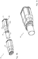
- eine perspektivische Explosionsansicht des Abgasauslasssystems gemäß
Figur 1 ; - Figur 2b
- eine perspektivische Ansicht des Abgasauslasssystems gemäß
Figur 2a in teilweise montiertem Zustand; - Figur 2c
- eine perspektivische Ansicht des Abgasauslasssystems gemäß
Figur 2b in vollständig montiertem Zustand; - Figur 2d
- eine schematische Seitenansicht eines Längsschnittes durch das Abgasauslasssystem gemäß
Figur 2c ; - Figur 3a
- eine perspektivische Ansicht mehrerer ringförmiger Befestigungselemente in Form von O-Ringen;
- Figuren 3b bis 3d
- perspektivische Ansichten weiterer ringförmiger Befestigungselemente in Form von Schlauchklemmen;
- Figur 3e
- eine perspektivische Ansicht eines weiteren ringförmigen Befestigungselements in Form eines teilweise unterbrochenen Metallrings und
- Figur 3f
- eine perspektivische Ansicht eines weiteren ringförmigen Befestigungselements in Form eines Federrings.
-
Figur 1 zeigt ein Kraftfahrzeug 10 mit einem Verbrennungsmotor 12 und einer mit dem Verbrennungsmotor 12 verbundenen Abgasanlage 14. Die Abgasanlage 14 ist fluidisch mit einem Abgasauslasssystem 16 verbunden. -
Figur 2a zeigt das Abgasauslasssystem 16. Das Abgasauslasssystem 16 weist ein Endrohr 18, eine Endrohrblendeninnenwandung 20 und eine Endrohrblendenaußenwandung 22 auf. InFigur 2a ist nur ein Teil des Endrohrs 18 dargestellt. Die Endrohrblendeninnenwandung 20 ist zweiteilig ausgebildet. Sie weist ein erstes Teil 20a und ein zweites Teil 20b auf. Im vorliegenden Fall ist die Endrohrblendeninnenwandung 20 parallel zur Längsachse 24 des Abgasauslasssystems 16 geteilt ausgebildet. Die Endrohrblendeninnenwandung 20 ist somit in axialer Richtung geteilt ausgebildet. - Allgemein werden im Sinne der vorliegenden Erfindung Richtungen parallel zur bzw. in Richtung der Längsachse 24 des Abgasauslasssystems 16 als "axial" und Richtungen senkrecht zur Längsachse 24 des Abgasauslasssystems 16 als "radial" bezeichnet.
- Die Teile 20a, 20b können miteinander verrastbar ausgebildet sein. Die Fixierung der Teile 20a, 20b erfolgt im vorliegenden Fall durch ein erstes ringförmiges Befestigungselement 26 und ein zweites ringförmiges Befestigungselement 28.
-
Figur 2b zeigt das Abgasauslasssystem 16, wobei die ringförmigen Befestigungselemente 26, 28 die Teile 20a, 20b radial verbinden und radial am Endrohr 18 halten. In einem abschließenden Montageschritt wird die Endrohrblendenaußenwandung 22 axial auf das Endrohr 18 in Richtung der Endrohrblendeninnenwandung 20 und weiter, zumindest zum überwiegenden Teil der Endrohrblendenaußenwandung 22, über die Endrohrblendeninnenwandung 20 geschoben. -
Figur 2c zeigt das Abgasauslasssystem 16 im vollständig montierten Zustand. -
Figur 2d zeigt schematisch einen axialen Schnitt durch das Abgasauslasssystem 16 gemäßFigur 2c . AusFigur 2d ist ersichtlich, dass das Abgasauslasssystem 16 im Wesentlichen axialsymmetrisch zur Längsachse 24 des Abgasauslasssystems 16 ausgebildet ist. Das Abgasauslasssystem 16 weist am Endrohr 18 eine erste ringförmige Mulde 30 auf. Weiterhin weist das Abgasauslasssystem 16 an der Endrohrblendeninnenwandung 20 eine zweite ringförmige Mulde 32 auf. Sowohl die erste ringförmige Mulde 30 als auch die zweite ringförmige Mulde 32 sind radial zur Längsachse 24 ausgebildet. Die erste ringförmige Mulde 30 schmiegt sich in die zweite ringförmige Mulde 32. Die erste ringförmige Mulde 30 stellt einen ersten Teil, die zweite ringförmige Mulde 32 einen zweiten Teil einer ersten Formschlussverbindung 34 des Abgasauslasssystems 16 dar. Die erste Formschlussverbindung 34 sichert die Endrohrblendeninnenwandung 20 gegen axiales Verschieben relativ zum Endrohr 18. Radial wird die Endrohrblendeninnenwandung 20 relativ zum Endrohr 18 durch das erste ringförmige Befestigungselement 26 gesichert. Das erste ringförmige Befestigungselement 26 ist dabei in einer Ringmuldenausnehmung 36 der Endrohrblendeninnenwandung 20 angeordnet und dadurch axial fixiert. - Die Endrohrblendenaußenwandung 22 weist eine dritte ringförmige Mulde 38 auf. Die dritte ringförmige Mulde 38 ist radial ausgebildet. Das erste ringförmige Befestigungselement 26 ist in der dritten ringförmigen Mulde 38 teilweise aufgenommen. Hierdurch entsteht eine zweite Formschlussverbindung 40, die die Endrohrblendenaußenwandung 22 axial relativ zur Endrohrblendeninnenwandung 22 fixiert.
- Eine vierte ringförmige Mulde 42 ist in der Endrohrblendeninnenwandung 20 im Auslassbereich des Abgasauslasssystems 16 ausgebildet. Das zweite ringförmige Befestigungselement 28 ist teilweise in der vierten ringförmigen Mulde 42 angeordnet. Die vierte ringförmige Mulde 42 ist radial ausgebildet. Weiterhin weist die Endrohrblendenaußenwandung 22 eine fünfte ringförmige Mulde 44 auf, in der das zweite ringförmige Befestigungselement 28 teilweise angeordnet ist. Die fünfte ringförmige Mulde 44 ist radial ausgebildet. Durch die vierte ringförmige Mulde 42, die fünfte ringförmige Mulde 44 und das zweite Befestigungselement 28 entsteht eine dritte Formschlussverbindung 46 des Abgasauslasssystems 16, die die Endrohrblendenaußenwandung 22 zusätzlich gegen axiales Verschieben relativ zur Endrohrblendeninnenwandung 20 sichert.
- Die Endrohrblendeninnenwandung 20 bildet zusammen mit der Endrohrblendenaußenwandung 22 eine Endrohrblende 45.
- Die
Figuren 3a bis 3f zeigen exemplarisch verschiedene Ausführungsformen ringförmiger Befestigungselemente 48a bis 48g zum Einsatz als erstes ringförmiges Befestigungselement 26 bzw. zweites ringförmiges Befestigungselement 28 (sieheFiguren 2a ,2b und2d ). -
Figur 3a zeigt ringförmige Befestigungselemente 48a, 48b in Form von O-Ringen, von denen aus Gründen der Übersichtlichkeit lediglich zwei O-Ringe mit einem Bezugszeichen versehen sind. - Die
Figuren 3b bis 3d zeigen verschiedene Ausführungsformen ringförmiger Befestigungselemente in Form von Schlauchschellen bzw. Schlauchklemmen 48c bis 48e. -
Figur 3e zeigt ein besonders bevorzugtes Ausführungsbeispiel eines ringförmigen Befestigungselements 48f. Das ringförmige Befestigungselement 48f ist in Form eines geöffneten Metallrings ausgebildet. Vorzugsweise ist das ringförmige Befestigungselement 48f in Form eines geöffneten Stahlrings ausgebildet. Wird zumindest ein ringförmiges Befestigungselement 26, 28 (sieheFiguren 2a ,2b und2d ) in Form eines ringförmigen Befestigungselements 48f gemäßFigur 3e ausgebildet, kann das Abgasauslasssystem 16 (sieheFiguren 1 und 2a bis 2d) konstruktiv besonders einfach und kostengünstig ausgebildet werden, -
Figur 3f zeigt ein weiteres ringförmiges Befestigungselement 48g in Form einer endlosen Spiralfeder. - Unter Vornahme einer Zusammenschau aller Figuren der Zeichnungen betrifft die vorliegende Erfindung zusammenfassend ein Abgasauslasssystem 16 für ein Kraftfahrzeug 10 mit einem Endrohr 18 und einer auf dem Endrohr 18 angeordneten Endrohrblende 45. Die Endrohrblende 45 ist durch eine Endrohrblendeninnenwandung 20 und eine Endrohrblendenaußenwandung 22 zumindest doppelwandig ausgebildet. Die Endrohrblendeninnenwandung 20 ist zumindest zweiteilig ausgebildet und radial um das Endrohr 18 schließbar. Die Endrohrblendeninnenwandung 20 ist zumindest teilweise formschlüssig an das Endrohr 18 anordenbar, sodass die Endrohrblendeninnenwandung 20 in ihrem am Endrohr 18 montierten Zustand nicht axial verschiebbar ist. Ein erstes ringförmiges Befestigungselement 26 hält die Endrohrblendeninnenwandung 20 radial fixiert am Endrohr 18. Die Endrohrblendenaußenwandung 22 ist axial über die Endrohrblendeninnenwandung 20 schiebbar. Die Endrohrblenden-außenwandung 22 ist vorzugsweise durch eine Rastverbindung axial an der Endrohrblendeninnenwandung 20 fixiert.
Claims (9)
- Abgasauslasssystem (16) für ein Kraftfahrzeug (10), wobei das Abgasauslasssystem (16) Folgendes aufweist:a) Ein Endrohr (18) zur fluidischen Verbindung mit einer Abgasanlage (14), wobei das Endrohr (18) einen ersten Teil einer ersten Formschlussverbindung (34) aufweist;b) Eine Endrohrblende (45) miti) einer zumindest zweiteiligen Endrohrblendeninnenwandung (20);ii) einer axial auf die Endrohrblendeninnenwandung (20) aufschiebbaren Endrohrblendenaußenwandung (22);c) Ein erstes ringförmiges Befestigungselement (26), das die zumindest zweiteilige Endrohrblendeninnenwandung (20) im Bereich des ersten Teils der ersten Formschlussverbindung (34) am Endrohr (18) radial fixiert, wobei das Abgasauslasssystem (16) an der Endrohrblendeninnenwandung (20) einen zweiten Teil der ersten Formschlussverbindung (34) zur zumindest teilweise formschlüssigen Anbindung der Endrohrblendeninnenwandung (20) an das erste ringförmige Befestigungselement (26) aufweist,dadurch gekennzeichnet, dass der erste Teil der ersten Formschlussverbindung (34) in Form einer ersten ringförmigen Mulde (30) ausgebildet ist und der zweite Teil der ersten Formschlussverbindung (34) in Form einer zweiten ringförmigen Mulde (32) ausgebildet ist.
- Abgasauslasssystem nach Anspruch 1, bei dem die Verbindung zwischen Endrohrblende (45) und Endrohr (18) ohne Stoffschluss erfolgt.
- Abgasauslasssystem nach einem der vorhergehenden Ansprüche, bei dem das Abgasauslasssystem (16) an der Endrohrblendenaußenwandung (22) eine dritte ringförmige Mulde (38) aufweist, in der das erste ringförmige Befestigungselement (26) zumindest teilweise angeordnet ist, sodass eine zweite Formschlussverbindung (40) ausgebildet wird.
- Abgasauslasssystem nach einem der vorhergehenden Ansprüche, bei dem das Abgasauslasssystem (16) ein zweites ringförmiges Befestigungselement (28) aufweist, das die zumindest zweiteilige Endrohrblendeninnenwandung (20) radial fixiert, wobei das zweite ringförmige Befestigungselement (28) dem ersten ringförmigen Befestigungselement (26) axial gegenüberliegend an der Endrohrblendeninnenwandung (20) angeordnet ist.
- Abgasauslasssystem nach Anspruch 4, bei dem das Abgasauslasssystem (16) an der zweiteiligen Endrohrblendeninnenwandung (20) eine vierte ringförmige Mulde (42) aufweist, in der das zweite ringförmige Befestigungselement (28) zumindest teilweise angeordnet ist.
- Abgasauslasssystem nach Anspruch 5, bei dem das Abgasauslasssystem (16) an der Endrohrblendenaußenwandung (22) eine fünfte ringförmige Mulde (44) aufweist, in der das zweite ringförmige Befestigungselement (28) zumindest teilweise angeordnet ist, sodass eine dritte Formschlussverbindung (46) ausgebildet wird.
- Kraftfahrzeug (10) mit einem Abgasauslasssystem (16) nach einem der Ansprüche 1 bis 6, wobei das Endrohr (18) fluidisch mit einer Abgasanlage (14) des Kraftfahrzeugs (10) verbunden ist.
- Verfahren zur Herstellung eines Abgasauslasssystems (16) für ein Kraftfahrzeug (10), wobei das Verfahren folgende Verfahrensschritte aufweist:I) Herstellen einer ersten ringförmigen Mulde (30) in einem Endrohr (18);II) Aufschieben einer Endrohrblendenaußenwandung (22) auf das Endrohr (18);III) Anordnen einer zumindest zweiteiligen Endrohrblendeninnenwandung (20) mit einer zweiten ringförmigen Mulde (32), am Endrohr (18) durch eine erste Formschlussverbindung (34) der zweiten ringförmigen Mulde (32) mit der ersten ringförmigen Mulde (30);IV) Fixieren der Endrohrblendeninnenwandung (20) mit einem ersten ringförmigen Befestigungselement (26) im Bereich der ersten ringförmigen Mulde (30);VI) Schieben der Endrohrblendenaußenwandung (22) über die Endrohrblendeninnenwandung (20).
- Verfahren nach Anspruch 8, bei dem das Verfahren folgenden Verfahrensschritt aufweist:
V) Fixieren der Endrohrblendeninnenwandung (20) mit einem zweiten ringförmigen Befestigungselement (28) in einem Bereich der Endrohrblendeninnenwandung (20), der dem Bereich, in dem das erste ringförmige Befestigungselement (26) angeordnet ist, axial entgegengesetzt ist.
Applications Claiming Priority (2)
| Application Number | Priority Date | Filing Date | Title |
|---|---|---|---|
| DE102016202056.0A DE102016202056B3 (de) | 2016-02-11 | 2016-02-11 | Abgasauslasssystem für ein Kraftfahrzeug, Kraftfahrzeug mit einem solchen Abgasauslasssystem sowie Verfahren zur Herstellung eines Abgasauslasssystems |
| PCT/EP2017/050513 WO2017137203A1 (de) | 2016-02-11 | 2017-01-12 | Abgasauslasssystem für ein kraftfahrzeug, kraftfahrzeug mit einem solchen abgasauslasssystem sowie verfahren zur herstellung eines abgasauslasssystems |
Publications (2)
| Publication Number | Publication Date |
|---|---|
| EP3414436A1 EP3414436A1 (de) | 2018-12-19 |
| EP3414436B1 true EP3414436B1 (de) | 2019-12-11 |
Family
ID=57860834
Family Applications (1)
| Application Number | Title | Priority Date | Filing Date |
|---|---|---|---|
| EP17700927.1A Active EP3414436B1 (de) | 2016-02-11 | 2017-01-12 | Abgasauslasssystem für ein kraftfahrzeug, kraftfahrzeug mit einem solchen abgasauslasssystem sowie verfahren zur herstellung eines abgasauslasssystems |
Country Status (4)
| Country | Link |
|---|---|
| US (1) | US10590828B2 (de) |
| EP (1) | EP3414436B1 (de) |
| DE (1) | DE102016202056B3 (de) |
| WO (1) | WO2017137203A1 (de) |
Families Citing this family (3)
| Publication number | Priority date | Publication date | Assignee | Title |
|---|---|---|---|---|
| DE102017214199B4 (de) * | 2017-08-15 | 2021-05-20 | Cisma Solutions Aps | Anordnung und Verfahren zur Befestigung einer Endrohrblende |
| DE102019121411A1 (de) | 2019-08-08 | 2021-02-11 | Eberspächer Exhaust Technology GmbH & Co. KG | Abgasbehandlungsbaugruppe |
| US12044348B2 (en) * | 2021-10-29 | 2024-07-23 | Nissan North America, Inc. | Vehicle body structure |
Family Cites Families (12)
| Publication number | Priority date | Publication date | Assignee | Title |
|---|---|---|---|---|
| US2244393A (en) * | 1939-08-31 | 1941-06-03 | Mackenzie Muffier Company Inc | Muffler |
| US2382159A (en) * | 1942-10-16 | 1945-08-14 | Harry A R Klemm | Muffler |
| US3106984A (en) * | 1962-01-09 | 1963-10-15 | Laclede Metal Products Co | Muffler construction |
| DE2703406C3 (de) * | 1977-01-27 | 1981-10-29 | Siemens AG, 1000 Berlin und 8000 München | Verbindugnsanordnung für koaxiale Leitungen |
| IT1095302B (it) * | 1977-04-28 | 1985-08-10 | Leistritz Hans Karl | Impianto di conduzione per apparecchi di gas con scarico nell'atmosfera libera,in particolare per elementi di azionamento a motore |
| DE19517462A1 (de) * | 1994-05-20 | 1995-11-23 | Audi Ag | Endrohr einer Abgasanlage |
| DE19914426C2 (de) * | 1999-03-30 | 2003-04-17 | Daimler Chrysler Ag | Doppelwandiges Endrohr für ein Abgasrohr einer Abgasanlage eines Kraftfahrzeuges |
| US7007720B1 (en) * | 2000-04-04 | 2006-03-07 | Lacks Industries, Inc. | Exhaust tip |
| FR2839533B1 (fr) * | 2002-05-07 | 2004-11-19 | Faurecia Sys Echappement | Dispositif nettoyable de depollution des gaz d'echappement d'un moteur |
| US8550122B2 (en) * | 2009-02-25 | 2013-10-08 | Nissan North America, Inc. | Exhaust finisher retention operation |
| KR20120127950A (ko) * | 2011-05-16 | 2012-11-26 | 현대자동차주식회사 | 차량용 배기장치의 테일파이프 구조 |
| DE102012023804B4 (de) * | 2012-12-05 | 2015-02-12 | Audi Ag | Abgasanlage eines Kraftfahrzeugs, mit einem von einer Endrohrblende wenigstens bereichsweise umgriffenen Endrohr |
-
2016
- 2016-02-11 DE DE102016202056.0A patent/DE102016202056B3/de not_active Expired - Fee Related
-
2017
- 2017-01-12 WO PCT/EP2017/050513 patent/WO2017137203A1/de not_active Ceased
- 2017-01-12 EP EP17700927.1A patent/EP3414436B1/de active Active
-
2018
- 2018-08-08 US US16/058,028 patent/US10590828B2/en active Active
Non-Patent Citations (1)
| Title |
|---|
| None * |
Also Published As
| Publication number | Publication date |
|---|---|
| US10590828B2 (en) | 2020-03-17 |
| WO2017137203A1 (de) | 2017-08-17 |
| DE102016202056B3 (de) | 2017-03-16 |
| EP3414436A1 (de) | 2018-12-19 |
| US20180347441A1 (en) | 2018-12-06 |
Similar Documents
| Publication | Publication Date | Title |
|---|---|---|
| EP3379129B1 (de) | Anschlussverbinder | |
| EP2501922B1 (de) | Saugrohrabschnitt und sauganlage | |
| DE3843659C2 (de) | Anschlußvorrichtung zwischen einer Kraftstoffrohrleitung und einem Einspritzventil einer Brennkraftmaschine | |
| WO2009007165A1 (de) | Ladeluftschlauch | |
| DE102016202056B3 (de) | Abgasauslasssystem für ein Kraftfahrzeug, Kraftfahrzeug mit einem solchen Abgasauslasssystem sowie Verfahren zur Herstellung eines Abgasauslasssystems | |
| DE10215980B4 (de) | Leckageanschluss für einen Kraftstoffinjektor | |
| EP2639423B1 (de) | Schalldämpfer-einheit | |
| EP3450812B1 (de) | Leitungskupplung und behälter hiermit | |
| DE102008051303A1 (de) | Verschlusskupplung | |
| EP1283351B1 (de) | Ansaugvorrichtung für eine Brennkraftmaschine | |
| DE102014011606B4 (de) | Abgassystem für eine Brennkraftmaschine | |
| DE102009021512A1 (de) | Luftfilter für eine Brennkraftmaschine | |
| DE10328144A1 (de) | Vorrichtung zur Schalldämpfung in einem Rohrkanal | |
| DE202011002772U1 (de) | Vorrichtung zum Dämpfen von Druckpulsationen | |
| DE102004016051A1 (de) | Bremskraftverstärker | |
| EP2910792A1 (de) | Verbindungseinrichtung für die fluidische verbindung eines fluidrohrabschnitts mit einem weiteren fluidrohrabschnitt | |
| EP1600683A1 (de) | Lösbare Kupplungsmuffe und Herstellungsverfahren für eine lösbare Kupplungsmuffe | |
| WO2015149779A1 (de) | Dichtelement für eine kupplungsglocke | |
| DE29814047U1 (de) | Preßfitting | |
| EP1389457B1 (de) | Vorrichtung für den Einsatz zur Verteilung von flüssigen und/oder gasförmigen Medien aus Schläuchen oder elastischen Rohren | |
| DE102013215709A1 (de) | Baugruppe für ein Kraftfahrzeug | |
| DE102016011157A1 (de) | Filtergehäuse aus Kunststoff und Filtersystem | |
| DE102013001045B4 (de) | Luftfilteranordnung | |
| EP1580409A2 (de) | Ölmodul | |
| DE102007012536A1 (de) | Schutzhülse für Leitungen |
Legal Events
| Date | Code | Title | Description |
|---|---|---|---|
| STAA | Information on the status of an ep patent application or granted ep patent |
Free format text: STATUS: UNKNOWN |
|
| STAA | Information on the status of an ep patent application or granted ep patent |
Free format text: STATUS: THE INTERNATIONAL PUBLICATION HAS BEEN MADE |
|
| PUAI | Public reference made under article 153(3) epc to a published international application that has entered the european phase |
Free format text: ORIGINAL CODE: 0009012 |
|
| STAA | Information on the status of an ep patent application or granted ep patent |
Free format text: STATUS: REQUEST FOR EXAMINATION WAS MADE |
|
| 17P | Request for examination filed |
Effective date: 20180719 |
|
| AK | Designated contracting states |
Kind code of ref document: A1 Designated state(s): AL AT BE BG CH CY CZ DE DK EE ES FI FR GB GR HR HU IE IS IT LI LT LU LV MC MK MT NL NO PL PT RO RS SE SI SK SM TR |
|
| AX | Request for extension of the european patent |
Extension state: BA ME |
|
| RIN1 | Information on inventor provided before grant (corrected) |
Inventor name: ORILLE, ANGEL Inventor name: RADTKE, SEBASTIAN Inventor name: EISELE, PHILIPP Inventor name: LARRAZ, JESUS Inventor name: KOEHNLEIN, SEBASTIAN |
|
| DAV | Request for validation of the european patent (deleted) | ||
| DAX | Request for extension of the european patent (deleted) | ||
| GRAP | Despatch of communication of intention to grant a patent |
Free format text: ORIGINAL CODE: EPIDOSNIGR1 |
|
| STAA | Information on the status of an ep patent application or granted ep patent |
Free format text: STATUS: GRANT OF PATENT IS INTENDED |
|
| INTG | Intention to grant announced |
Effective date: 20190701 |
|
| GRAS | Grant fee paid |
Free format text: ORIGINAL CODE: EPIDOSNIGR3 |
|
| GRAA | (expected) grant |
Free format text: ORIGINAL CODE: 0009210 |
|
| STAA | Information on the status of an ep patent application or granted ep patent |
Free format text: STATUS: THE PATENT HAS BEEN GRANTED |
|
| AK | Designated contracting states |
Kind code of ref document: B1 Designated state(s): AL AT BE BG CH CY CZ DE DK EE ES FI FR GB GR HR HU IE IS IT LI LT LU LV MC MK MT NL NO PL PT RO RS SE SI SK SM TR |
|
| REG | Reference to a national code |
Ref country code: GB Ref legal event code: FG4D Free format text: NOT ENGLISH |
|
| REG | Reference to a national code |
Ref country code: CH Ref legal event code: EP |
|
| REG | Reference to a national code |
Ref country code: AT Ref legal event code: REF Ref document number: 1212407 Country of ref document: AT Kind code of ref document: T Effective date: 20191215 |
|
| REG | Reference to a national code |
Ref country code: DE Ref legal event code: R096 Ref document number: 502017003111 Country of ref document: DE |
|
| REG | Reference to a national code |
Ref country code: IE Ref legal event code: FG4D Free format text: LANGUAGE OF EP DOCUMENT: GERMAN |
|
| REG | Reference to a national code |
Ref country code: NL Ref legal event code: MP Effective date: 20191211 |
|
| REG | Reference to a national code |
Ref country code: LT Ref legal event code: MG4D |
|
| PG25 | Lapsed in a contracting state [announced via postgrant information from national office to epo] |
Ref country code: FI Free format text: LAPSE BECAUSE OF FAILURE TO SUBMIT A TRANSLATION OF THE DESCRIPTION OR TO PAY THE FEE WITHIN THE PRESCRIBED TIME-LIMIT Effective date: 20191211 Ref country code: GR Free format text: LAPSE BECAUSE OF FAILURE TO SUBMIT A TRANSLATION OF THE DESCRIPTION OR TO PAY THE FEE WITHIN THE PRESCRIBED TIME-LIMIT Effective date: 20200312 Ref country code: BG Free format text: LAPSE BECAUSE OF FAILURE TO SUBMIT A TRANSLATION OF THE DESCRIPTION OR TO PAY THE FEE WITHIN THE PRESCRIBED TIME-LIMIT Effective date: 20200311 Ref country code: NO Free format text: LAPSE BECAUSE OF FAILURE TO SUBMIT A TRANSLATION OF THE DESCRIPTION OR TO PAY THE FEE WITHIN THE PRESCRIBED TIME-LIMIT Effective date: 20200311 Ref country code: SE Free format text: LAPSE BECAUSE OF FAILURE TO SUBMIT A TRANSLATION OF THE DESCRIPTION OR TO PAY THE FEE WITHIN THE PRESCRIBED TIME-LIMIT Effective date: 20191211 Ref country code: LV Free format text: LAPSE BECAUSE OF FAILURE TO SUBMIT A TRANSLATION OF THE DESCRIPTION OR TO PAY THE FEE WITHIN THE PRESCRIBED TIME-LIMIT Effective date: 20191211 Ref country code: LT Free format text: LAPSE BECAUSE OF FAILURE TO SUBMIT A TRANSLATION OF THE DESCRIPTION OR TO PAY THE FEE WITHIN THE PRESCRIBED TIME-LIMIT Effective date: 20191211 |
|
| PG25 | Lapsed in a contracting state [announced via postgrant information from national office to epo] |
Ref country code: HR Free format text: LAPSE BECAUSE OF FAILURE TO SUBMIT A TRANSLATION OF THE DESCRIPTION OR TO PAY THE FEE WITHIN THE PRESCRIBED TIME-LIMIT Effective date: 20191211 Ref country code: RS Free format text: LAPSE BECAUSE OF FAILURE TO SUBMIT A TRANSLATION OF THE DESCRIPTION OR TO PAY THE FEE WITHIN THE PRESCRIBED TIME-LIMIT Effective date: 20191211 |
|
| PG25 | Lapsed in a contracting state [announced via postgrant information from national office to epo] |
Ref country code: AL Free format text: LAPSE BECAUSE OF FAILURE TO SUBMIT A TRANSLATION OF THE DESCRIPTION OR TO PAY THE FEE WITHIN THE PRESCRIBED TIME-LIMIT Effective date: 20191211 |
|
| PG25 | Lapsed in a contracting state [announced via postgrant information from national office to epo] |
Ref country code: NL Free format text: LAPSE BECAUSE OF FAILURE TO SUBMIT A TRANSLATION OF THE DESCRIPTION OR TO PAY THE FEE WITHIN THE PRESCRIBED TIME-LIMIT Effective date: 20191211 Ref country code: ES Free format text: LAPSE BECAUSE OF FAILURE TO SUBMIT A TRANSLATION OF THE DESCRIPTION OR TO PAY THE FEE WITHIN THE PRESCRIBED TIME-LIMIT Effective date: 20191211 Ref country code: PT Free format text: LAPSE BECAUSE OF FAILURE TO SUBMIT A TRANSLATION OF THE DESCRIPTION OR TO PAY THE FEE WITHIN THE PRESCRIBED TIME-LIMIT Effective date: 20200506 Ref country code: EE Free format text: LAPSE BECAUSE OF FAILURE TO SUBMIT A TRANSLATION OF THE DESCRIPTION OR TO PAY THE FEE WITHIN THE PRESCRIBED TIME-LIMIT Effective date: 20191211 Ref country code: CZ Free format text: LAPSE BECAUSE OF FAILURE TO SUBMIT A TRANSLATION OF THE DESCRIPTION OR TO PAY THE FEE WITHIN THE PRESCRIBED TIME-LIMIT Effective date: 20191211 Ref country code: RO Free format text: LAPSE BECAUSE OF FAILURE TO SUBMIT A TRANSLATION OF THE DESCRIPTION OR TO PAY THE FEE WITHIN THE PRESCRIBED TIME-LIMIT Effective date: 20191211 |
|
| REG | Reference to a national code |
Ref country code: DE Ref legal event code: R119 Ref document number: 502017003111 Country of ref document: DE |
|
| PG25 | Lapsed in a contracting state [announced via postgrant information from national office to epo] |
Ref country code: SM Free format text: LAPSE BECAUSE OF FAILURE TO SUBMIT A TRANSLATION OF THE DESCRIPTION OR TO PAY THE FEE WITHIN THE PRESCRIBED TIME-LIMIT Effective date: 20191211 Ref country code: IS Free format text: LAPSE BECAUSE OF FAILURE TO SUBMIT A TRANSLATION OF THE DESCRIPTION OR TO PAY THE FEE WITHIN THE PRESCRIBED TIME-LIMIT Effective date: 20200411 Ref country code: SK Free format text: LAPSE BECAUSE OF FAILURE TO SUBMIT A TRANSLATION OF THE DESCRIPTION OR TO PAY THE FEE WITHIN THE PRESCRIBED TIME-LIMIT Effective date: 20191211 |
|
| REG | Reference to a national code |
Ref country code: CH Ref legal event code: PL |
|
| PG25 | Lapsed in a contracting state [announced via postgrant information from national office to epo] |
Ref country code: MC Free format text: LAPSE BECAUSE OF FAILURE TO SUBMIT A TRANSLATION OF THE DESCRIPTION OR TO PAY THE FEE WITHIN THE PRESCRIBED TIME-LIMIT Effective date: 20191211 |
|
| REG | Reference to a national code |
Ref country code: BE Ref legal event code: MM Effective date: 20200131 |
|
| PLBE | No opposition filed within time limit |
Free format text: ORIGINAL CODE: 0009261 |
|
| STAA | Information on the status of an ep patent application or granted ep patent |
Free format text: STATUS: NO OPPOSITION FILED WITHIN TIME LIMIT |
|
| PG25 | Lapsed in a contracting state [announced via postgrant information from national office to epo] |
Ref country code: DK Free format text: LAPSE BECAUSE OF FAILURE TO SUBMIT A TRANSLATION OF THE DESCRIPTION OR TO PAY THE FEE WITHIN THE PRESCRIBED TIME-LIMIT Effective date: 20191211 Ref country code: LU Free format text: LAPSE BECAUSE OF NON-PAYMENT OF DUE FEES Effective date: 20200112 Ref country code: DE Free format text: LAPSE BECAUSE OF NON-PAYMENT OF DUE FEES Effective date: 20200801 |
|
| 26N | No opposition filed |
Effective date: 20200914 |
|
| PG25 | Lapsed in a contracting state [announced via postgrant information from national office to epo] |
Ref country code: BE Free format text: LAPSE BECAUSE OF NON-PAYMENT OF DUE FEES Effective date: 20200131 Ref country code: CH Free format text: LAPSE BECAUSE OF NON-PAYMENT OF DUE FEES Effective date: 20200131 Ref country code: SI Free format text: LAPSE BECAUSE OF FAILURE TO SUBMIT A TRANSLATION OF THE DESCRIPTION OR TO PAY THE FEE WITHIN THE PRESCRIBED TIME-LIMIT Effective date: 20191211 Ref country code: LI Free format text: LAPSE BECAUSE OF NON-PAYMENT OF DUE FEES Effective date: 20200131 |
|
| PG25 | Lapsed in a contracting state [announced via postgrant information from national office to epo] |
Ref country code: FR Free format text: LAPSE BECAUSE OF NON-PAYMENT OF DUE FEES Effective date: 20200211 Ref country code: IT Free format text: LAPSE BECAUSE OF FAILURE TO SUBMIT A TRANSLATION OF THE DESCRIPTION OR TO PAY THE FEE WITHIN THE PRESCRIBED TIME-LIMIT Effective date: 20191211 Ref country code: IE Free format text: LAPSE BECAUSE OF NON-PAYMENT OF DUE FEES Effective date: 20200112 |
|
| PG25 | Lapsed in a contracting state [announced via postgrant information from national office to epo] |
Ref country code: PL Free format text: LAPSE BECAUSE OF FAILURE TO SUBMIT A TRANSLATION OF THE DESCRIPTION OR TO PAY THE FEE WITHIN THE PRESCRIBED TIME-LIMIT Effective date: 20191211 |
|
| PG25 | Lapsed in a contracting state [announced via postgrant information from national office to epo] |
Ref country code: TR Free format text: LAPSE BECAUSE OF FAILURE TO SUBMIT A TRANSLATION OF THE DESCRIPTION OR TO PAY THE FEE WITHIN THE PRESCRIBED TIME-LIMIT Effective date: 20191211 Ref country code: MT Free format text: LAPSE BECAUSE OF FAILURE TO SUBMIT A TRANSLATION OF THE DESCRIPTION OR TO PAY THE FEE WITHIN THE PRESCRIBED TIME-LIMIT Effective date: 20191211 Ref country code: CY Free format text: LAPSE BECAUSE OF FAILURE TO SUBMIT A TRANSLATION OF THE DESCRIPTION OR TO PAY THE FEE WITHIN THE PRESCRIBED TIME-LIMIT Effective date: 20191211 |
|
| PG25 | Lapsed in a contracting state [announced via postgrant information from national office to epo] |
Ref country code: MK Free format text: LAPSE BECAUSE OF FAILURE TO SUBMIT A TRANSLATION OF THE DESCRIPTION OR TO PAY THE FEE WITHIN THE PRESCRIBED TIME-LIMIT Effective date: 20191211 |
|
| REG | Reference to a national code |
Ref country code: AT Ref legal event code: MM01 Ref document number: 1212407 Country of ref document: AT Kind code of ref document: T Effective date: 20220112 |
|
| PG25 | Lapsed in a contracting state [announced via postgrant information from national office to epo] |
Ref country code: AT Free format text: LAPSE BECAUSE OF NON-PAYMENT OF DUE FEES Effective date: 20220112 |
|
| PGFP | Annual fee paid to national office [announced via postgrant information from national office to epo] |
Ref country code: GB Payment date: 20240124 Year of fee payment: 8 |
|
| GBPC | Gb: european patent ceased through non-payment of renewal fee |
Effective date: 20250112 |
|
| PG25 | Lapsed in a contracting state [announced via postgrant information from national office to epo] |
Ref country code: GB Free format text: LAPSE BECAUSE OF NON-PAYMENT OF DUE FEES Effective date: 20250112 |