EP3412832A1 - Vorrichtung zur steuerung von bewegungen eines front- oder heckseitigen anbaugeräts einer pistenraupe und pistenraupe - Google Patents
Vorrichtung zur steuerung von bewegungen eines front- oder heckseitigen anbaugeräts einer pistenraupe und pistenraupe Download PDFInfo
- Publication number
- EP3412832A1 EP3412832A1 EP18173094.6A EP18173094A EP3412832A1 EP 3412832 A1 EP3412832 A1 EP 3412832A1 EP 18173094 A EP18173094 A EP 18173094A EP 3412832 A1 EP3412832 A1 EP 3412832A1
- Authority
- EP
- European Patent Office
- Prior art keywords
- attachment
- snowcat
- vehicle frame
- carrier
- movements
- Prior art date
- Legal status (The legal status is an assumption and is not a legal conclusion. Google has not performed a legal analysis and makes no representation as to the accuracy of the status listed.)
- Granted
Links
Images





Classifications
-
- E—FIXED CONSTRUCTIONS
- E01—CONSTRUCTION OF ROADS, RAILWAYS, OR BRIDGES
- E01H—STREET CLEANING; CLEANING OF PERMANENT WAYS; CLEANING BEACHES; DISPERSING OR PREVENTING FOG IN GENERAL CLEANING STREET OR RAILWAY FURNITURE OR TUNNEL WALLS
- E01H4/00—Working on surfaces of snow or ice in order to make them suitable for traffic or sporting purposes, e.g. by compacting snow
- E01H4/02—Working on surfaces of snow or ice in order to make them suitable for traffic or sporting purposes, e.g. by compacting snow for sporting purposes, e.g. preparation of ski trails; Construction of artificial surfacings for snow or ice sports ; Trails specially adapted for on-the-snow vehicles, e.g. devices adapted for ski-trails
Definitions
- the invention relates to a device for controlling movements of a front or rear attachment of a snowcat with a built-up of several cylinders kinematics system, which can be converted by means of a control unit in different functional positions, the pivoting movements of the implement about a vertical axis, a transverse axis and a longitudinal axis and a Include parallel displacement in the vertical direction.
- the invention also relates to a snowcat with such a device.
- Such a device for controlling movements of a front attachment of a snowcat is generally known in a snowcat of the brand "PistenBully" the applicant.
- the well-known snowcat has front as an attachment on a plow blade, which is controllable by means of a kinematics system.
- the kinematics system has a plurality of hydraulic actuating cylinders which are adjustable via a controllable by a joystick in a cab of the snow groomer control unit and thus generate movements of the dozer blade.
- the plow blade can be pivoted upwards and downwards by means of the kinematics system about pivot axes extending in the vehicle transverse direction, about a pivot axis extending in the vehicle vertical direction are pivoted to the left and to the right, tilted about a pivot axis extending in the vehicle longitudinal direction and parallel displaced parallelogram pivoting movements of the kinematics system in the vertical direction become.
- the kinematic system comprises, in addition to a plurality of hydraulic actuating cylinders, a base part hinged to the front of a vehicle frame, horizontally extended in a starting position, and a base part, which is pivotable in the vehicle transverse direction, on which two actuating cylinders engage.
- a vertically oriented carrier is pivotally mounted on a remote from the vehicle frame side to which the plow blade is attached.
- the object of the invention is to provide a device and a snowcat of the type mentioned, which allow additional functionality with little effort.
- the kinematics system is additionally designed such that the attachment in a horizontal plane in the transverse direction and / or longitudinal direction relative to a vehicle frame of the snow groomer is translationally and / or parallel displaceable.
- the kinematics system can be arranged on the front or rear of the snow groomer, depending on whether a front or a rear attachment are operated should.
- the additional mobility according to the invention makes it possible to displace the attachment in a horizontal plane in a translational manner to the front or to the rear, thus exerting push or pull movements.
- the attachment is in the horizontal plane in the transverse direction either translational or parallel displaceable.
- the horizontal plane is to be understood as a vehicle level spanned by the vehicle transverse direction and the vehicle longitudinal direction, which is aligned parallel to the ground when the snowcat is positioned on a horizontal surface.
- a front attachment especially a dozer blade is provided.
- a rear attachment especially a rear tiller is provided.
- it can be provided as a rear-mounted attachment a track device and as a front attachment a gripper, a front tiller or the like.
- the kinematics system is designed as a self-supporting Hexapod system.
- self-supporting is to be understood that the kinematic system in addition to the parking cylinders requires no additional support elements, which are extended between the vehicle frame and the attachment, and thus carries the respective attachment freely.
- the mobility of the attachment depends exclusively on the mobility of the Hexapod system.
- a change in the distance in the vehicle longitudinal direction between the attachment and the vehicle frame is possible.
- such additional functionality does not arise, since the base, which extends between the vehicle frame and the attachment, is only pivotally articulated to the vehicle frame, without allowing a translational extension or retraction function.
- the self-supporting hexapod system consists exclusively of adjusting cylinders, each of which has a linearly movable retractable and retractable actuating piston.
- the actuator cylinders of the Hexapod system extend essentially forward or backward, depending on the front or rear attachment point on the snow groomer. As a result, the respective attachment in the longitudinal direction of the snow groomer is spaced from this and arranged cantilevered by the hexapod system.
- the hexapod system on six actuating cylinder which are arranged in the manner of a hexapod with an end portion on the vehicle frame and articulated with an opposite end portion on a support which is provided for attachment of the attachment.
- the six actuating cylinders are articulated on the vehicle frame and carry with their opposite end portions of the carrier, so that it is connected exclusively via the actuating cylinder to the vehicle frame.
- the carrier is designed for releasably securing the attachment.
- the carrier is preferably provided with a receptacle on the side opposite the articulation of the actuating cylinder.
- articulation points for the actuating cylinders on the carrier for the attachment are designed in each case as Doppelanlenk Schemee for two actuating cylinders. As a result, two actuating cylinders in each case engage in pairs, each with a double articulation region. This simplifies the connection of the actuating cylinder to the carrier.
- the kinematic system is associated with a measuring sensor, which detects movements and positions of the actuating cylinder and forwards to the control unit, and that the control unit has a memory for at least one predetermined control function of each actuating cylinder, which is retrievable depending on detected signals of the measurement sensor.
- predefined control functions can be automatically initiated and executed for the displacement of the carrier and thus of the attachment attached thereto.
- the control unit preferably controls electronically corresponding hydraulic circuits of the preferably hydraulic actuating cylinders, wherein the control unit is associated with software that processes corresponding signals of the measuring sensor and converts the respective desired control function. Different function programs or automatic movements can be stored and implemented.
- Appropriate points on the vehicle frame are provided as reference for the measuring signals of the measuring sensors.
- Corresponding control functions of the actuating cylinder and thus the displacement of the respective attachment can either be generated via a control element in the form of a joystick by a driver of the snowcat or stored as a completed function programs that need only be activated by a simple control element such as a switch or the like then perform an automated movement to a corresponding end position such as a parking position.
- At least one manually operable operating member is provided, which is provided for retrieving the at least one control function by a driver of the snow groomer.
- Such an operating member may be an operating switch, a control knob, an operating lever or the like.
- the operating member is preferably arranged in the access area of a driver-side seating position within a driver's cab of the snowcat.
- the object underlying the invention is achieved in that it has at least one provided front and / or rear side device, as described with reference to the previous paragraphs.
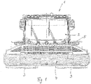
- a snowcat 1 after the Fig. 1 to 17 has a driver's cab 2, which is positioned on the front of a vehicle frame 8.
- the snowcat 1 is provided with a tracked chassis comprising two crawler tracks 3 on opposite sides of the vehicle frame 8.
- the snowcat 1 is intended for the design and preparation of snow slopes.
- the snowcat 1 has both a front-mounted attachment in the form of a dozer blade 4 and a rear-mounted attachment in the form of a rear moulder 5.
- the plow blade 4 is arranged on the front side of the vehicle frame 8 of the snowcat 1 by means of a device for controlling movements of the plow blade 4.
- the device has a kinematics system, which is designed as a hexapod system 6 and described in more detail below.
- the hexapod system 6 has a total of six hydraulic actuating cylinders 9 to 11, which are mounted at the rear on a front of the vehicle frame 8 in the region of corresponding articulation points 15 to 17 pivotally mounted at least substantially in the vehicle transverse direction pivot axes.
- Each adjusting cylinder 9 to 11 has in each case a piston rod, which is articulated at an opposite end region of the adjusting cylinder 9 to 11 in the region of a carrier 7, which is oriented substantially upright.
- a total of three Doppelanlenk Schemee 12 to 14 are provided for articulation of the actuating cylinders 9 to 11, of which a central Doppelanlenk Scheme 13 in the region of an upper side of the carrier 7 and two lateral Doppelansch Schemee 12, 14 are provided in the region of an underside of the carrier 7.
- the total of six actuating cylinders 9 to 11 are positioned in pairs relative to one another according to a hexapod, wherein two upper actuating cylinders 10 are guided starting from an upper articulation region 17 on the vehicle frame 8 to the central double articulation region 13.
- the carrier 7 is supported by the total of six actuating cylinders 9 to 11 of the hexapod system 6, as shown by the Fig. 3 is clearly recognizable.
- the carrier 7 is provided on an opposite to the Doppelansch Schemeen 12 to 14 front side with a unspecified receptacle for holding the dozer blade 4.
- the plow blade 4 is preferably releasably attached to the carrier 7.
- a control unit not shown is provided, which is designed electronically and acts by means of electronic control commands to an electro-hydraulic control of the actuating cylinder 9 to 11.
- Each adjusting cylinder 9 to 11 is in each case assigned a measuring sensor, which together form a measuring sensor system in the sense of the invention.
- the measuring sensors can detect movements and positions of the adjusting cylinders 9 to 11 in relation to the vehicle frame 8, wherein corresponding receptacles on the vehicle frame 8 at the articulation areas 15 to 17 serve as reference points for the detection of the corresponding measuring signals.
- the measuring sensor is connected to the electronic control unit, which has an electronic memory for at least one control function program, which includes automated movements and positioning for the carrier 7 and thus for the plow blade 4 and is realized by software.
- the detected measurement signals of the measurement sensor system are compared with setpoint values of the predefined control programs and evaluated so that the control unit can control the positioning cylinders 9 to 11 in accordance with the desired control functions.
- An activation of the corresponding control functions takes place in the area of a driver's seat position within the driver's cab 2 by a corresponding manually operable actuator.
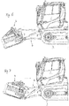
- control device By the described control device can be carried out by means of the hexapod system also described a plurality of control movements for the plow blade 4, which are based on the 4 to 17 are explained. So it is according to the 4 and 5 possible to shift the carrier 7 and thus the plow blade 4 translationally in the vehicle longitudinal direction to the front or to the rear, which by the two arrows in the 4 and 5 is clarified.
- the carrier 7 including the hexapod system 6 and the plow blade 4 can be pivoted up or down about an imaginary pivot axis extending in the vehicle transverse direction in the region of the vehicle frame 8.
- the Nachuntenverschwenken down to below a defined by an underside of the chain chassis 3 level.
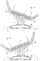
- the carrier 7 by means of the Hexapod system 6 by a vehicle in the vertical direction extending pivot axis to the right ( Fig. 12 ) or to the left ( Fig. 13 ) to be turned around.
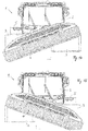
- the Hexapod system 6 is also provided to the plow blade 4 and thus also the carrier of the control device to an axis extending in the vehicle longitudinal axis of rotation to the left ( Fig. 14 ) or to the right ( Fig. 15 ) to twist.
- Such twisting is also referred to as tilting because it defines a limited rotation about a vehicle longitudinal axis.
- the plow blade 4 including the carrier 7 in a plane defined by a vehicle transverse direction and a vehicle longitudinal direction horizontal plane translationally to the left ( Fig. 16 ) or translated translationally to the right.
Landscapes
- Engineering & Computer Science (AREA)
- Architecture (AREA)
- Civil Engineering (AREA)
- Structural Engineering (AREA)
- Body Structure For Vehicles (AREA)
Abstract
Description
- Die Erfindung betrifft eine Vorrichtung zur Steuerung von Bewegungen eines front- oder heckseitigen Anbaugeräts einer Pistenraupe mit einem aus mehreren Stellzylindern aufgebauten Kinematiksystem, das mittels einer Steuereinheit in verschiedene Funktionsstellungen überführbar ist, die Schwenkbewegungen des Anbaugeräts um eine Hochachse, eine Querachse und eine Längsachse sowie eine Parallelverlagerung in Hochrichtung umfassen. Die Erfindung betrifft zudem eine Pistenraupe mit einer solchen Vorrichtung.
- Eine derartige Vorrichtung zur Steuerung von Bewegungen eines frontseitigen Anbaugeräts einer Pistenraupe ist bei einer Pistenraupe der Marke "PistenBully" der Anmelderin allgemein bekannt. Die bekannte Pistenraupe weist frontseitig als Anbaugerät einen Räumschild auf, der mittels eines Kinematiksystems steuerbar ist. Das Kinematiksystem weist mehrere hydraulische Stellzylinder auf, die über eine durch einen Joystick in einem Fahrerhaus der Pistenraupe aktivierbare Steuereinheit verstellbar sind und so Bewegungen des Räumschilds erzeugen. Der Räumschild kann mittels des Kinematiksystems um in Fahrzeugquerrichtung erstreckte Schwenkachsen nach oben und nach unten geschwenkt werden, um eine in Fahrzeughochrichtung erstreckte Schwenkachse nach links und nach rechts geschwenkt werden, um eine in Fahrzeuglängsrichtung erstreckte Schwenkachse gekippt werden und durch Parallelogrammschwenkbewegungen des Kinematiksystems in Hochrichtung parallel verlagert werden. Das Kinematiksystem umfasst neben mehreren hydraulischen Stellzylindern ein an einem Fahrzeugrahmen frontseitig angelenktes, in einer Ausgangsstellung horizontal erstrecktes und um eine in Fahrzeugquerrichtung schwenkbewegliches Grundteil, an dem zwei Stellzylinder angreifen. An dem Grundteil ist auf einer zu dem Fahrzeugrahmen abliegenden Seite ein hochkant ausgerichteter Träger schwenkbeweglich gelagert, an dem der Räumschild befestigt ist.
- Aufgabe der Erfindung ist es, eine Vorrichtung und eine Pistenraupe der eingangs genannten Art zu schaffen, die mit geringem Aufwand zusätzliche Funktionalitäten ermöglichen.
- Diese Aufgabe wird dadurch gelöst, dass das Kinematiksystem zusätzlich derart gestaltet ist, dass das Anbaugerät in einer Horizontalebene in Querrichtung und/oder Längsrichtung relativ zu einem Fahrzeugrahmen der Pistenraupe translatorisch und/oder parallel verlagerbar ist. Hierdurch ergeben sich zusätzliche Bewegungsmöglichkeiten für das Anbaugerät, wodurch die Einsatzmöglichkeiten des Anbaugeräts und demzufolge die Funktionalität der Pistenraupe verbessert werden. Das Kinematiksystem kann frontseitig oder heckseitig an der Pistenraupe angeordnet sein, je nachdem, ob ein frontseitiges oder ein heckseitiges Anbaugerät bedient werden soll. Durch die erfindungsgemäße zusätzliche Beweglichkeit ist es möglich, das Anbaugerät in einer Horizontalebene translatorisch nach vorne oder nach hinten zu verlagern und so Schub- oder Zugbewegungen auszuüben. Alternativ oder ergänzend ist das Anbaugerät in der Horizontalebene in Querrichtung entweder translatorisch oder parallel verlagerbar. Unter der Horizontalebene ist eine durch die Fahrzeugquerrichtung und die Fahrzeuglängsrichtung aufgespannte Fahrzeugebene zu verstehen, die bei einer Positionierung der Pistenraupe auf horizontalem Untergrund parallel zu dem Untergrund ausgerichtet ist. Als frontseitiges Anbaugerät ist insbesondere ein Räumschild vorgesehen. Als heckseitiges Anbaugerät ist insbesondere eine Heckfräse vorgesehen. Alternativ kann als heckseitiges Anbaugerät ein Loipenspurgerät und als frontseitiges Anbaugerät ein Greifer, eine Frontfräse oder Ähnliches vorgesehen sein.
- Die der Erfindung zugrunde liegende Aufgabe wird auch dadurch gelöst, dass das Kinematiksystem als selbsttragendes Hexapod-System gestaltet ist. Unter dem Begriff "selbsttragend" ist zu verstehen, dass das Kinematiksystem neben den Stellzylindern keine zusätzlichen Trägerelemente benötigt, die zwischen dem Fahrzeugrahmen und dem Anbaugerät erstreckt sind, und somit das jeweilige Anbaugerät frei trägt. Hierdurch ist vorteilhaft die Beweglichkeit des Anbaugeräts ausschließlich von der Beweglichkeit des Hexapod-Systems abhängig. Hierdurch ist insbesondere eine Veränderung des Abstands in Fahrzeuglängsrichtung zwischen dem Anbaugerät und dem Fahrzeugrahmen möglich. Beim Stand der Technik ergibt sich eine solche zusätzliche Funktionalität nicht, da das Grundteil, das sich zwischen dem Fahrzeugrahmen und dem Anbaugerät erstreckt, lediglich schwenkbeweglich am Fahrzeugrahmen angelenkt ist, ohne eine translatorische Ausfahr- oder Einfahrfunktion zu ermöglichen. Das selbsttragende Hexapod-System besteht ausschließlich aus Stellzylindern, die jeweils für sich gesehen einen linearbeweglichen aus- und einfahrbaren Stellkolben aufweisen. Die Stellzylinder des Hexapod-Systems erstrecken sich im Wesentlichen nach vorne oder nach hinten, je nach front- oder rückseitiger Anbaustelle an der Pistenraupe. Dadurch ist das jeweilige Anbaugerät in Längsrichtung der Pistenraupe beabstandet zu dieser angeordnet und freitragend gehalten durch das Hexapod-System.
- In Ausgestaltung der Erfindung weist das Hexapod-System sechs Stellzylinder auf, die nach Art eines Hexapods mit einem Endbereich an dem Fahrzeugrahmen angeordnet und mit einem gegenüberliegenden Endbereich an einem Träger angelenkt sind, der zur Befestigung des Anbaugeräts vorgesehen ist. Die sechs Stellzylinder sind am Fahrzeugrahmen angelenkt und tragen mit ihren gegenüberliegenden Endbereichen den Träger, so dass dieser ausschließlich über die Stellzylinder mit dem Fahrzeugrahmen verbunden ist.
- In weiterer Ausgestaltung der Erfindung ist der Träger zur lösbaren Befestigung des Anbaugeräts ausgebildet. Hierzu ist der Träger vorzugsweise mit einer Aufnahme auf der der Anlenkung der Stellzylinder gegenüberliegenden Seite versehen. In weiterer Ausgestaltung der Erfindung sind Anlenkpunkte für die Stellzylinder an dem Träger für das Anbaugerät jeweils als Doppelanlenkbereiche für jeweils zwei Stellzylinder gestaltet. Demzufolge greifen jeweils zwei Stellzylinder paarweise an jeweils einem Doppelanlenkbereich an. Dies vereinfacht die Anbindung der Stellzylinder an den Träger.
- In weiterer Ausgestaltung der Erfindung ist dem Kinematiksystem eine Messsensorik zugeordnet, die Bewegungen oder Stellungen der Stellzylinder erfasst und an die Steuereinheit weiterleitet, und dass die Steuereinheit einen Speicher für wenigstens eine vorgegebene Steuerfunktion jedes Stellzylinders aufweist, die abhängig von erfassten Signalen der Messsensorik abrufbar ist. Dadurch können vorgegebene Steuerfunktionen automatisiert für die Verlagerung des Trägers und damit des an diesem befestigten Anbaugeräts eingeleitet und ausgeführt werden. Die Steuereinheit steuert vorzugsweise elektronisch entsprechende Hydraulikkreise der vorzugsweise hydraulischen Stellzylinder, wobei der Steuereinheit eine Software zugeordnet ist, die entsprechende Signale der Messsensorik verarbeitet und die jeweils gewünschte Steuerfunktion umsetzt. Dabei können unterschiedliche Funktionsprogramme oder Bewegungsautomatismen hinterlegt sein und umgesetzt werden. Als Referenz für die Messsignale der Messsensorik sind geeignete Punkte am Fahrzeugrahmen vorgesehen. Entsprechende Steuerfunktionen der Stellzylinder und damit der Verlagerung des jeweiligen Anbaugeräts können entweder über ein Bedienelement in Form eines Joysticks von einem Fahrer der Pistenraupe erzeugt oder aber als fertiggestellte Funktionsprogramme abgelegt sein, die lediglich durch ein einfaches Bedienelement wie einen Schalter oder Ähnliches aktiviert werden müssen, um dann einen automatisierten Bewegungsablauf bis zu einer entsprechenden Endposition wie beispielsweise einer Parkposition durchzuführen.
- In weiterer Ausgestaltung ist wenigstens ein manuell betätigbares Bedienglied vorgesehen, das zum Abrufen der wenigstens einen Steuerfunktion durch einen Fahrer der Pistenraupe vorgesehen ist. Ein solches Bedienglied kann ein Bedienschalter, ein Bedienknopf, ein Bedienhebel oder Ähnliches sein. Das Bedienglied ist vorzugsweise im Zugriffsbereich einer fahrerseitigen Sitzposition innerhalb einer Fahrerkabine der Pistenraupe angeordnet.
- Für die Pistenraupe der eingangs genannten Art wird die der Erfindung zugrunde liegende Aufgabe dadurch gelöst, dass diese wenigstens eine front- und/oder heckseitig vorgesehene Vorrichtung aufweist, wie sie anhand der vorherigen Absätze beschrieben wurde.
- Weitere Vorteile und Merkmale der Erfindung ergeben sich aus den Ansprüchen sowie aus der nachfolgenden Beschreibung eines bevorzugten Ausführungsbeispiels der Erfindung, das anhand der Zeichnungen dargestellt ist.
- Fig. 1
- zeigt eine Ausführungsform einer erfindungsgemäßen Pistenraupe in einer Frontansicht,
- Fig. 2
- in einer Draufsicht einen Teilbereich der Pistenraupe nach
Fig. 1 im Bereich eines frontseitigen Anbaugeräts und mit einer Ausführungsform einer erfindungsgemäßen Vorrichtung zur Steuerung des frontseitigen Anbaugeräts, - Fig. 3
- eine Seitenansicht der Pistenraupe im Bereich des frontseitigen Anbaugeräts mit der Vorrichtung gemäß
Fig. 2 , - Fig. 4 und 5
- die Pistenraupe gemäß den
Fig. 1 bis 3 mit in Längsrichtung erfolgten translatorischen Verlagerungen des Anbaugeräts, - Fig. 6 und 7
- die Pistenraupe gemäß den
Fig. 1 bis 5 mit einem durch die Vorrichtung angehobenen bzw. abgesenkten Anbaugerät, - Fig. 8 und 9
- die Pistenraupe nach den
Fig. 1 bis 7 mit parallel nach unten bzw. nach oben verlagertem Anbaugerät, - Fig. 10 und11
- die Pistenraupe nach den
Fig. 1 bis 9 mit nach oben bzw. nach unten verschwenktem Anbaugerät, - Fig. 12 und 13
- in einer Draufsicht die Pistenraupe nach den
Fig. 1 bis 11 mit nach rechts bzw. nach links verschwenktem Anbaugerät, - Fig. 14 und 15
- die Pistenraupe nach den
Fig. 1 bis 13 mit einem um eine in Fahrzeuglängsrichtung erstreckte Schwenkachse nach links bzw. nach rechts verdrehtem Anbaugerät und - Fig. 16 und 17
- die Pistenraupe nach den
Fig. 1 bis 15 mit translatorisch nach links bzw. nach rechts verlagertem Anbaugerät. - Eine Pistenraupe 1 nach den
Fig. 1 bis 17 weist ein Fahrerhaus 2 auf, das frontseitig auf einem Fahrzeugrahmen 8 positioniert ist. Die Pistenraupe 1 ist mit einem Kettenfahrwerk versehen, das zwei Kettenlaufwerke 3 auf gegenüberliegenden Seiten des Fahrzeugrahmens 8 umfasst. Die Pistenraupe 1 ist für die Gestaltung und Präparierung von Schneepisten vorgesehen. Hierzu weist die Pistenraupe 1 sowohl ein frontseitiges Anbaugerät in Form eines Räumschilds 4 als auch ein heckseitiges Anbaugerät in Form einer Heckfräse 5 auf. - Der Räumschild 4 ist mittels einer Vorrichtung zur Steuerung von Bewegungen des Räumschilds 4 frontseitig an dem Fahrzeugrahmen 8 der Pistenraupe 1 angeordnet. Die Vorrichtung weist ein Kinematiksystem auf, das als Hexapod-System 6 ausgeführt und nachfolgend näher beschrieben ist.
- Das Hexapod-System 6 weist insgesamt sechs hydraulische Stellzylinder 9 bis 11 auf, die rückseitig an einer Front des Fahrzeugrahmens 8 im Bereich entsprechender Anlenkpunkte 15 bis 17 um zumindest im Wesentlichen in Fahrzeugquerrichtung erstreckte Schwenkachsen schwenkbeweglich gelagert sind. Jeder Stellzylinder 9 bis 11 weist jeweils eine Kolbenstange auf, die an einem gegenüberliegenden Endbereich des Stellzylinders 9 bis 11 im Bereich eines Trägers 7 angelenkt ist, der im Wesentlichen hochkant ausgerichtet ist. Zur Anlenkung der Stellzylinder 9 bis 11 sind insgesamt drei Doppelanlenkbereiche 12 bis 14 vorgesehen, von denen ein mittlerer Doppelanlenkbereich 13 im Bereich einer Oberseite des Trägers 7 und zwei seitliche Doppelanlenkbereiche 12, 14 im Bereich einer Unterseite des Trägers 7 vorgesehen sind. Die insgesamt sechs Stellzylinder 9 bis 11 sind gemäß eines Hexapods jeweils paarweise zueinander positioniert, wobei zwei obere Stellzylinder 10 ausgehend von einem oberen Anlenkbereich 17 am Fahrzeugrahmen 8 zu dem mittleren Doppelanlenkbereich 13 geführt sind. Die beiden in der Draufsicht gemäß
Fig. 2 links angeordneten Stellzylinder 9, von denen ein Stellzylinder 9 an dem oberen Anlenkbereich 16 und der andere Stellzylinder 9 an dem unteren Anlenkbereich 15 angelenkt ist, sind mit ihren gegenüberliegenden Endbereichen, d.h. den Kolbenstangen, an dem in der Draufsicht gemäßFig. 2 linken unteren Doppelanlenkbereich 14 angelenkt. Entsprechend spiegelsymmetrisch zu einer vertikalen Fahrzeugmittellängsachse sind die gegenüberliegenden beiden Stellzylinder 11 auf der rechten Seite am Fahrzeugrahmen 8 ebenfalls im Bereich eines oberen Anlenkbereichs 16 einerseits und eines unteren Anlenkbereichs 15 andererseits angelenkt und erstrecken sich nach vorne zu dem Träger 7 hin. An dem Träger 7 sind die beiden Stellzylinder 11 im Bereich des rechten unteren Doppelanlenkbereichs 12 (in der Draufsicht gemäßFig. 2 gesehen) angelenkt. Alle Stellzylinder 9 bis 11 sind als doppelt wirkende Stellzylinder ausgeführt, so dass sie hydraulisch gesteuert eingefahren und ausgefahren werden können. - Der Träger 7 wird durch die insgesamt sechs Stellzylinder 9 bis 11 des Hexapod-Systems 6 frei getragen, wie anhand der
Fig. 3 gut erkennbar ist. Der Träger 7 ist auf einer zu den Doppelanlenkbereichen 12 bis 14 gegenüberliegenden Frontseite mit einer nicht näher bezeichneten Aufnahme zur Halterung des Räumschilds 4 versehen. Der Räumschild 4 ist an dem Träger 7 vorzugsweise lösbar befestigt. - Zur Steuerung des Hexapod-Systems 6 ist eine nicht näher dargestellte Steuereinheit vorgesehen, die elektronisch ausgeführt ist und mittels elektronischer Steuerbefehle auf eine elektrohydraulische Steuerung der Stellzylinder 9 bis 11 einwirkt. Jedem Stellzylinder 9 bis 11 ist jeweils ein Messsensor zugeordnet, die gemeinsam eine Messsensorik im Sinne der Erfindung bilden. Die Messsensoren können Bewegungen und Stellungen der Stellzylinder 9 bis 11 im Verhältnis zum Fahrzeugrahmen 8 erfassen, wobei entsprechende Aufnahmen am Fahrzeugrahmen 8 an den Anlenkbereichen 15 bis 17 als Referenzpunkte für die Erfassung der entsprechenden Messsignale dienen. Die Messsensorik ist angeschlossen an die elektronische Steuereinheit, die einen elektronischen Speicher für wenigstens ein Steuerfunktionsprogramm aufweist, das automatisierte Bewegungsabläufe und Positionierungen für den Träger 7 und damit für den Räumschild 4 umfasst und durch eine Software realisiert ist. Die erfassten Messsignale der Messsensorik werden mit Sollwerten der vorgegebenen Steuerprogramme verglichen und ausgewertet, damit die Steuereinheit die Stellzylinder 9 bis 11 entsprechend den gewünschten Steuerfunktionen steuern kann. Eine Aktivierung der entsprechenden Steuerfunktionen erfolgt im Bereich einer Fahrersitzposition innerhalb der Fahrerkabine 2 durch ein entsprechendes manuell bedienbares Betätigungsglied.
- Durch die beschriebene Steuerungsvorrichtung kann mittels des ebenfalls beschriebenen Hexapod-Systems eine Vielzahl von Steuerbewegungen für den Räumschild 4 durchgeführt werden, die anhand der
Fig. 4 bis 17 erläutert sind. So ist es gemäß denFig. 4 und 5 möglich, den Träger 7 und damit den Räumschild 4 translatorisch in Fahrzeuglängsrichtung nach vorne oder nach hinten zu verlagern, was durch die beiden Pfeile in denFig. 4 und 5 verdeutlicht ist. - Zusätzlich ist es gemäß den
Fig. 6 und 7 möglich, den Träger 7 und damit den Räumschild 4 nach vorne unten abzukippen oder schräg nach oben anzustellen. Die entsprechenden Bewegungen, die durch das Hexapod-System 6 durchgeführt werden, sind erneut durch die beiden Pfeile in denFig. 6 und 7 dargestellt. - Außerdem ist es möglich, den Träger 7 und damit den Räumschild 4 translatorisch oder parallel in Hochrichtung nach oben oder nach unten zu verlagern, wie anhand der
Fig. 8 und 9 dargestellt ist. Auch hier sind die entsprechenden Bewegungsrichtungen durch die beiden Pfeile verdeutlicht. - Eine weitere Bewegungsfunktion ist anhand der
Fig. 10 und 11 erläutert. Der Träger 7 einschließlich des Hexapod-Systems 6 und des Räumschilds 4 kann um eine im Bereich des Fahrzeugrahmens 8 in Fahrzeugquerrichtung erstreckte, imaginäre Schwenkachse nach oben oder nach unten verschwenkt werden. Dabei erfolgt das Nachuntenverschwenken bis unterhalb einer durch eine Unterseite des Kettenfahrwerks 3 definierte Ebene. - Gemäß den
Fig. 12 und 13 (siehe dort ebenfalls die beiden Pfeildarstellungen) kann der Träger 7 mittels des Hexapod-Systems 6 um eine in Fahrzeughochrichtung erstreckte Schwenkachse nach rechts (Fig. 12 ) oder nach links (Fig. 13 ) gedreht werden. - Gemäß den
Fig. 14 und 15 ist das Hexapod-System 6 auch dazu vorgesehen, den Räumschild 4 und damit auch den Träger der Steuerungsvorrichtung um eine in Fahrzeuglängsrichtung erstreckte Drehachse nach links (Fig. 14 ) oder nach rechts (Fig. 15 ) zu verdrehen. Ein derartiges Verdrehen wird auch als Tilten bezeichnet, da es eine begrenzte Rotation um eine Fahrzeuglängsachse definiert. - Gemäß den Darstellungen nach den
Fig. 16 und 17 kann der Räumschild 4 einschließlich des Trägers 7 auch in einer durch eine Fahrzeugquerrichtung und eine Fahrzeuglängsrichtung aufgespannten Horizontalebene translatorisch nach links (Fig. 16 ) oder translatorisch nach rechts verlagert werden. - Die große Anzahl von Bewegungsmöglichkeiten ermöglicht für die Pistenraupe 1 zusätzliche Funktionalitäten, die insbesondere bei der Erstellung von Funparks in Skigebieten vorteilhaft sind.
Claims (8)
- Vorrichtung zur Steuerung von Bewegungen eines front- oder heckseitigen Anbaugeräts (4) einer Pistenraupe (1) mit einem aus mehreren Stellzylindern (9 bis 11) aufgebauten Kinematiksystem, das mittels einer Steuereinheit in verschiedene Funktionsstellungen überführbar ist, die Schwenkbewegungen des Anbaugeräts um eine Hochachse, eine Querachse und eine Längsachse sowie eine Parallelverlagerung in Hochrichtung umfassen, dadurch gekennzeichnet, dass das Kinematiksystem zusätzlich derart gestaltet ist, dass das Anbaugerät (4) in einer Horizontalebene in Querrichtung und/oder Längsrichtung relativ zu einem Fahrzeugrahmen (8) der Pistenraupe (1) translatorisch und/oder parallel verlagerbar ist.
- Vorrichtung nach dem Oberbegriff des Anspruchs 1 oder nach Anspruch 1, dadurch gekennzeichnet, dass das Kinematiksystem als selbsttragendes Hexapod-System (6) gestaltet ist.
- Vorrichtung nach Anspruch 2, dadurch gekennzeichnet, dass das Hexapod-System (6) sechs Stellzylinder (9 bis 11) aufweist, die nach Art eines Hexapods mit einem Endbereich an dem Fahrzeugrahmen (8) angeordnet und mit einem gegenüberliegenden Endbereich an einem Träger (7) angelenkt sind, der zur Befestigung des Anbaugeräts (4) vorgesehen ist.
- Vorrichtung nach Anspruch 3, dadurch gekennzeichnet, dass der Träger (7) zur lösbaren Befestigung des Anbaugeräts (4) ausgebildet ist.
- Vorrichtung nach einem der Ansprüche 3 oder 4, dadurch gekennzeichnet, dass Anlenkpunkte für die Stellzylinder (9 bis 11) an dem Träger (7) für das Anbaugerät (4) jeweils als Doppelanlenkbereiche (12 bis 14) für jeweils zwei Stellzylinder (9 bis 11) gestaltet sind.
- Vorrichtung nach einem der vorhergehenden Ansprüche, dadurch gekennzeichnet, dass dem Kinematiksystem eine Messsensorik zugeordnet ist, die Bewegungen oder Stellungen der Stellzylinder erfasst und an die Steuereinheit weiterleitet, und dass die Steuereinheit einen Speicher für wenigstens eine vorgegebene Steuerfunktion jedes Stellzylinders aufweist, die abhängig von erfassten Signalen der Messsensorik abrufbar ist.
- Vorrichtung nach Anspruch 6, dadurch gekennzeichnet, dass wenigstens ein manuell betätigbares Bedienglied vorgesehen ist, das zum Abrufen der wenigstens einen Steuerfunktion durch einen Fahrer der Pistenraupe vorgesehen ist.
- Pistenraupe mit wenigstens einer Vorrichtung nach einem der vorhergehenden Ansprüche.
Applications Claiming Priority (1)
| Application Number | Priority Date | Filing Date | Title |
|---|---|---|---|
| DE102017209707.8A DE102017209707A1 (de) | 2017-06-08 | 2017-06-08 | Vorrichtung zur Steuerung von Bewegungen eines front- oder heckseitigen Anbaugeräts einer Pistenraupe und Pistenraupe |
Publications (2)
| Publication Number | Publication Date |
|---|---|
| EP3412832A1 true EP3412832A1 (de) | 2018-12-12 |
| EP3412832B1 EP3412832B1 (de) | 2020-08-19 |
Family
ID=62200359
Family Applications (1)
| Application Number | Title | Priority Date | Filing Date |
|---|---|---|---|
| EP18173094.6A Active EP3412832B1 (de) | 2017-06-08 | 2018-05-18 | Pistenraupe mit vorrichtung zur steuerung von bewegungen eines frontseitigen anbaugeräts |
Country Status (3)
| Country | Link |
|---|---|
| US (1) | US11105058B2 (de) |
| EP (1) | EP3412832B1 (de) |
| DE (1) | DE102017209707A1 (de) |
Families Citing this family (3)
| Publication number | Priority date | Publication date | Assignee | Title |
|---|---|---|---|---|
| KR102873416B1 (ko) * | 2019-03-19 | 2025-10-17 | 두산 밥캣 노스 아메리카, 인크. | 굴착기 블레이드 실린더 |
| US12146292B2 (en) * | 2019-07-11 | 2024-11-19 | Rose Welding & Crane Service, Inc. | Reconfigurable box blade |
| DE102021211674A1 (de) * | 2021-10-15 | 2023-04-20 | Kässbohrer Geländefahrzeug Aktiengesellschaft | Computergestütztes Verfahren zur Pflege einer Schneepiste sowie computergestütztes System zur Durchführung des Verfahrens |
Citations (5)
| Publication number | Priority date | Publication date | Assignee | Title |
|---|---|---|---|---|
| JPS60104463U (ja) * | 1983-12-20 | 1985-07-16 | 株式会社 日本除雪機製作所 | 作業具昇降支持装置における要素ジヨイント構造 |
| DE19951840A1 (de) * | 1999-10-28 | 2001-05-10 | Deere & Co | Anbauschnittstelle zur Kopplung von Arbeitsgeräten an ein Arbeitsfahrzeug |
| US6354023B1 (en) * | 1998-12-15 | 2002-03-12 | Bombardier Inc. | Snow groomers and control system therefor |
| DE10114092A1 (de) * | 2001-03-22 | 2002-09-26 | Deere & Co | Geräteschnittstelle zwischen Arbeitsfahrzeug und Gerät |
| US20130185963A1 (en) * | 2007-10-30 | 2013-07-25 | Rolic Invest S.Ar.L. | Hitch device for connecting a groomer vehicle and a ski slope snow grooming implement, and control method employing such a hitch device |
Family Cites Families (24)
| Publication number | Priority date | Publication date | Assignee | Title |
|---|---|---|---|---|
| BE759307A (fr) * | 1970-01-09 | 1971-05-24 | Caterpillar Tractor Co | Ensemble de support et de reglage de la position d'une lame de bulldozer |
| US3913684A (en) * | 1974-12-13 | 1975-10-21 | Caterpillar Tractor Co | Implement mounting arrangement having lifting and angling capability |
| DE2559040C3 (de) * | 1975-01-06 | 1979-01-18 | Mitsubishi Jukogyo K.K., Tokio | Planierfahrzeug mit einem Planierschild |
| US4083414A (en) * | 1975-12-30 | 1978-04-11 | Kabushiki Kaisha Komatsu Seisakusho | Combination angling-tilting bulldozer |
| CA1034376A (en) * | 1976-03-26 | 1978-07-11 | J.I. Case Company | Angle control for dozer blade |
| US4111268A (en) * | 1976-04-28 | 1978-09-05 | J. I. Case Company | Scraper blade control |
| US4120366A (en) * | 1977-08-31 | 1978-10-17 | J. I. Case Company | Mounting arrangement for dozer blade |
| US4201268A (en) * | 1978-10-23 | 1980-05-06 | J. I. Case Company | Adjustment mechanism for dozer blade |
| USRE31642E (en) * | 1979-01-29 | 1984-08-07 | Caterpillar Tractor Co. | Angle and tilt implement assembly |
| US4572315A (en) * | 1984-02-09 | 1986-02-25 | Valley Engineering, Inc. | Power hitch |
| US4815223A (en) * | 1988-01-04 | 1989-03-28 | West Mountain Sales, Inc. | Snow grooming vehicle and attachments |
| US5010961A (en) * | 1990-02-20 | 1991-04-30 | J. I. Case Company | Angle-tilt-pitch mechanism for dozer blade |
| US6059048A (en) * | 1999-02-04 | 2000-05-09 | Caterpillar Inc. | Implement mounting arrangement with independent lift-roll and pitch-yaw operability |
| EP1199622B1 (de) * | 2000-10-20 | 2007-12-12 | Deere & Company | Bedienungselement |
| DE10111529A1 (de) * | 2001-03-10 | 2002-09-12 | Deere & Co | Vorrichtung zum Koppeln eines Gerätes an einem Arbeitsfahrzeug |
| DE10114091A1 (de) * | 2001-03-22 | 2002-09-26 | Deere & Co | Steuervorrichtung für eine Fahrzeuganbauschnittstelle |
| DE10220998A1 (de) * | 2002-05-11 | 2003-11-27 | Deere & Co | Anbauvorrichtung für ein Arbeitsfahrzeug |
| DE10247058A1 (de) * | 2002-10-09 | 2004-04-22 | Deere & Company, Moline | Geräteschnittstelle zur Kopplung von Arbeitsgeräten an ein Arbeitsfahrzeug und Ventilanordnung |
| US6827155B1 (en) * | 2003-07-18 | 2004-12-07 | Ronald J. Hoffart | Implement mounting system |
| DE102014200899A1 (de) * | 2013-12-20 | 2015-06-25 | Kässbohrer Geländefahrzeug AG | Pistenraupe und Räumschild für eine derartige Pistenraupe |
| NZ726923A (en) * | 2014-06-10 | 2018-06-29 | Progressive Ip Ltd | Blade levelling apparatus and mounting system |
| US10676894B2 (en) * | 2014-06-10 | 2020-06-09 | Progressive Ip Limited | Blade levelling apparatus with provision for mounted accessories |
| US20160108603A1 (en) * | 2015-10-27 | 2016-04-21 | Caterpillar Inc. | System for controlling earthworking implement |
| EP3205563B1 (de) * | 2016-02-11 | 2021-07-07 | Kässbohrer Geländefahrzeug AG | Pistenraupe zur pflege und gestaltung von schneegelände |
-
2017
- 2017-06-08 DE DE102017209707.8A patent/DE102017209707A1/de not_active Ceased
-
2018
- 2018-05-18 EP EP18173094.6A patent/EP3412832B1/de active Active
- 2018-06-06 US US16/001,229 patent/US11105058B2/en not_active Expired - Fee Related
Patent Citations (5)
| Publication number | Priority date | Publication date | Assignee | Title |
|---|---|---|---|---|
| JPS60104463U (ja) * | 1983-12-20 | 1985-07-16 | 株式会社 日本除雪機製作所 | 作業具昇降支持装置における要素ジヨイント構造 |
| US6354023B1 (en) * | 1998-12-15 | 2002-03-12 | Bombardier Inc. | Snow groomers and control system therefor |
| DE19951840A1 (de) * | 1999-10-28 | 2001-05-10 | Deere & Co | Anbauschnittstelle zur Kopplung von Arbeitsgeräten an ein Arbeitsfahrzeug |
| DE10114092A1 (de) * | 2001-03-22 | 2002-09-26 | Deere & Co | Geräteschnittstelle zwischen Arbeitsfahrzeug und Gerät |
| US20130185963A1 (en) * | 2007-10-30 | 2013-07-25 | Rolic Invest S.Ar.L. | Hitch device for connecting a groomer vehicle and a ski slope snow grooming implement, and control method employing such a hitch device |
Also Published As
| Publication number | Publication date |
|---|---|
| US20180355568A1 (en) | 2018-12-13 |
| US11105058B2 (en) | 2021-08-31 |
| EP3412832B1 (de) | 2020-08-19 |
| DE102017209707A1 (de) | 2018-12-13 |
Similar Documents
| Publication | Publication Date | Title |
|---|---|---|
| EP2455543B1 (de) | Gleitschalungsfertiger | |
| EP3084079B1 (de) | Pistenraupe | |
| DE3027489C2 (de) | ||
| DE102017009249B4 (de) | Kleinfertiger sowie Verfahren zum Betrieb eines Kleinfertigers | |
| EP3412832B1 (de) | Pistenraupe mit vorrichtung zur steuerung von bewegungen eines frontseitigen anbaugeräts | |
| DE4316364A1 (de) | Mehrzweck-Arbeits-Fahrzeug | |
| DE8708508U1 (de) | Loipenspurgerät | |
| EP1197369A2 (de) | Windschott für ein Cabriolet-Fahrzeug | |
| EP3741916A1 (de) | Mobiles arbeitsgerät mit verschwenkbarer fahrerkabine | |
| DE2835270A1 (de) | Strassenhobel mit einer aufhaengung fuer seine schneidvorrichtung | |
| DE3218525C2 (de) | Böschungsmähgerät | |
| DE69119491T2 (de) | Reinigungsfahrzeuge | |
| EP0551160A1 (de) | Geräteträger zum Anbau an selbstfahrende Fahrzeuge, insbesondere zum Präparieren von Skipisten | |
| EP4212670B1 (de) | Pistenraupe mit einem fahrerhaus sowie mit einer heckfräse und heckfräse für eine derartige pistenraupe | |
| DE102006034562A1 (de) | Anbaumäher | |
| EP3054367B1 (de) | Fahrzeug, insbesondere kettenfahrzeug zur schneepistengestaltung und -pflege | |
| DE19820377C1 (de) | Arbeitsfahrzeug mit kippbarer Fahrerplattform und Kippvorrichtung | |
| EP1734190A1 (de) | Vorrichtung zum Bearbeiten von Strassenbauflächen | |
| DE2606019A1 (de) | Rahmen fuer ein raupenfahrzeug | |
| DE3744821C2 (en) | Mowing attachment for tractor | |
| DE20312137U1 (de) | Fahrzeug zum Sammeln und Transportieren von Abfällen mit einer am Fahrzeugheck angeordneten Laderaumanordnung zum Aufnehmen von seitlich neben dem Fahrzeug aufgestellten Abfallgefäßen | |
| AT4622U1 (de) | Steuerknüppel für einen bagger | |
| EP0133637A1 (de) | Frontseitige Geräteanbauvorrichtung für ein frontverkleidetes land- und/oder bauwirtschaftlich nutzbares Kraftfahrzeug, insbesondere Ackerschlepper | |
| DE3990519C2 (de) | Fahrzeug zum Enteisen von Flugzeugen | |
| DE3834505C2 (de) | Bagger mit einem Steuereinheiten enthaltenden Fahrerhaus |
Legal Events
| Date | Code | Title | Description |
|---|---|---|---|
| PUAI | Public reference made under article 153(3) epc to a published international application that has entered the european phase |
Free format text: ORIGINAL CODE: 0009012 |
|
| STAA | Information on the status of an ep patent application or granted ep patent |
Free format text: STATUS: THE APPLICATION HAS BEEN PUBLISHED |
|
| AK | Designated contracting states |
Kind code of ref document: A1 Designated state(s): AL AT BE BG CH CY CZ DE DK EE ES FI FR GB GR HR HU IE IS IT LI LT LU LV MC MK MT NL NO PL PT RO RS SE SI SK SM TR |
|
| AX | Request for extension of the european patent |
Extension state: BA ME |
|
| STAA | Information on the status of an ep patent application or granted ep patent |
Free format text: STATUS: REQUEST FOR EXAMINATION WAS MADE |
|
| 17P | Request for examination filed |
Effective date: 20190524 |
|
| RBV | Designated contracting states (corrected) |
Designated state(s): AL AT BE BG CH CY CZ DE DK EE ES FI FR GB GR HR HU IE IS IT LI LT LU LV MC MK MT NL NO PL PT RO RS SE SI SK SM TR |
|
| STAA | Information on the status of an ep patent application or granted ep patent |
Free format text: STATUS: EXAMINATION IS IN PROGRESS |
|
| RIC1 | Information provided on ipc code assigned before grant |
Ipc: E01H 4/02 20060101AFI20191108BHEP |
|
| 17Q | First examination report despatched |
Effective date: 20191121 |
|
| GRAP | Despatch of communication of intention to grant a patent |
Free format text: ORIGINAL CODE: EPIDOSNIGR1 |
|
| STAA | Information on the status of an ep patent application or granted ep patent |
Free format text: STATUS: GRANT OF PATENT IS INTENDED |
|
| INTG | Intention to grant announced |
Effective date: 20200429 |
|
| RIN1 | Information on inventor provided before grant (corrected) |
Inventor name: HOLZAPFEL, SVEN |
|
| GRAS | Grant fee paid |
Free format text: ORIGINAL CODE: EPIDOSNIGR3 |
|
| GRAA | (expected) grant |
Free format text: ORIGINAL CODE: 0009210 |
|
| STAA | Information on the status of an ep patent application or granted ep patent |
Free format text: STATUS: THE PATENT HAS BEEN GRANTED |
|
| AK | Designated contracting states |
Kind code of ref document: B1 Designated state(s): AL AT BE BG CH CY CZ DE DK EE ES FI FR GB GR HR HU IE IS IT LI LT LU LV MC MK MT NL NO PL PT RO RS SE SI SK SM TR |
|
| REG | Reference to a national code |
Ref country code: CH Ref legal event code: EP |
|
| REG | Reference to a national code |
Ref country code: DE Ref legal event code: R096 Ref document number: 502018002212 Country of ref document: DE |
|
| REG | Reference to a national code |
Ref country code: AT Ref legal event code: REF Ref document number: 1304069 Country of ref document: AT Kind code of ref document: T Effective date: 20200915 |
|
| REG | Reference to a national code |
Ref country code: IE Ref legal event code: FG4D Free format text: LANGUAGE OF EP DOCUMENT: GERMAN |
|
| REG | Reference to a national code |
Ref country code: CH Ref legal event code: NV Representative=s name: DR. LUSUARDI AG, CH |
|
| REG | Reference to a national code |
Ref country code: LT Ref legal event code: MG4D |
|
| REG | Reference to a national code |
Ref country code: NL Ref legal event code: MP Effective date: 20200819 |
|
| PG25 | Lapsed in a contracting state [announced via postgrant information from national office to epo] |
Ref country code: LT Free format text: LAPSE BECAUSE OF FAILURE TO SUBMIT A TRANSLATION OF THE DESCRIPTION OR TO PAY THE FEE WITHIN THE PRESCRIBED TIME-LIMIT Effective date: 20200819 Ref country code: PT Free format text: LAPSE BECAUSE OF FAILURE TO SUBMIT A TRANSLATION OF THE DESCRIPTION OR TO PAY THE FEE WITHIN THE PRESCRIBED TIME-LIMIT Effective date: 20201221 Ref country code: HR Free format text: LAPSE BECAUSE OF FAILURE TO SUBMIT A TRANSLATION OF THE DESCRIPTION OR TO PAY THE FEE WITHIN THE PRESCRIBED TIME-LIMIT Effective date: 20200819 Ref country code: SE Free format text: LAPSE BECAUSE OF FAILURE TO SUBMIT A TRANSLATION OF THE DESCRIPTION OR TO PAY THE FEE WITHIN THE PRESCRIBED TIME-LIMIT Effective date: 20200819 Ref country code: NO Free format text: LAPSE BECAUSE OF FAILURE TO SUBMIT A TRANSLATION OF THE DESCRIPTION OR TO PAY THE FEE WITHIN THE PRESCRIBED TIME-LIMIT Effective date: 20201119 Ref country code: FI Free format text: LAPSE BECAUSE OF FAILURE TO SUBMIT A TRANSLATION OF THE DESCRIPTION OR TO PAY THE FEE WITHIN THE PRESCRIBED TIME-LIMIT Effective date: 20200819 Ref country code: BG Free format text: LAPSE BECAUSE OF FAILURE TO SUBMIT A TRANSLATION OF THE DESCRIPTION OR TO PAY THE FEE WITHIN THE PRESCRIBED TIME-LIMIT Effective date: 20201119 Ref country code: GR Free format text: LAPSE BECAUSE OF FAILURE TO SUBMIT A TRANSLATION OF THE DESCRIPTION OR TO PAY THE FEE WITHIN THE PRESCRIBED TIME-LIMIT Effective date: 20201120 |
|
| PG25 | Lapsed in a contracting state [announced via postgrant information from national office to epo] |
Ref country code: RS Free format text: LAPSE BECAUSE OF FAILURE TO SUBMIT A TRANSLATION OF THE DESCRIPTION OR TO PAY THE FEE WITHIN THE PRESCRIBED TIME-LIMIT Effective date: 20200819 Ref country code: LV Free format text: LAPSE BECAUSE OF FAILURE TO SUBMIT A TRANSLATION OF THE DESCRIPTION OR TO PAY THE FEE WITHIN THE PRESCRIBED TIME-LIMIT Effective date: 20200819 Ref country code: NL Free format text: LAPSE BECAUSE OF FAILURE TO SUBMIT A TRANSLATION OF THE DESCRIPTION OR TO PAY THE FEE WITHIN THE PRESCRIBED TIME-LIMIT Effective date: 20200819 Ref country code: PL Free format text: LAPSE BECAUSE OF FAILURE TO SUBMIT A TRANSLATION OF THE DESCRIPTION OR TO PAY THE FEE WITHIN THE PRESCRIBED TIME-LIMIT Effective date: 20200819 Ref country code: IS Free format text: LAPSE BECAUSE OF FAILURE TO SUBMIT A TRANSLATION OF THE DESCRIPTION OR TO PAY THE FEE WITHIN THE PRESCRIBED TIME-LIMIT Effective date: 20201219 |
|
| PG25 | Lapsed in a contracting state [announced via postgrant information from national office to epo] |
Ref country code: SM Free format text: LAPSE BECAUSE OF FAILURE TO SUBMIT A TRANSLATION OF THE DESCRIPTION OR TO PAY THE FEE WITHIN THE PRESCRIBED TIME-LIMIT Effective date: 20200819 Ref country code: RO Free format text: LAPSE BECAUSE OF FAILURE TO SUBMIT A TRANSLATION OF THE DESCRIPTION OR TO PAY THE FEE WITHIN THE PRESCRIBED TIME-LIMIT Effective date: 20200819 Ref country code: DK Free format text: LAPSE BECAUSE OF FAILURE TO SUBMIT A TRANSLATION OF THE DESCRIPTION OR TO PAY THE FEE WITHIN THE PRESCRIBED TIME-LIMIT Effective date: 20200819 Ref country code: CZ Free format text: LAPSE BECAUSE OF FAILURE TO SUBMIT A TRANSLATION OF THE DESCRIPTION OR TO PAY THE FEE WITHIN THE PRESCRIBED TIME-LIMIT Effective date: 20200819 Ref country code: EE Free format text: LAPSE BECAUSE OF FAILURE TO SUBMIT A TRANSLATION OF THE DESCRIPTION OR TO PAY THE FEE WITHIN THE PRESCRIBED TIME-LIMIT Effective date: 20200819 |
|
| REG | Reference to a national code |
Ref country code: DE Ref legal event code: R097 Ref document number: 502018002212 Country of ref document: DE |
|
| PG25 | Lapsed in a contracting state [announced via postgrant information from national office to epo] |
Ref country code: ES Free format text: LAPSE BECAUSE OF FAILURE TO SUBMIT A TRANSLATION OF THE DESCRIPTION OR TO PAY THE FEE WITHIN THE PRESCRIBED TIME-LIMIT Effective date: 20200819 Ref country code: AL Free format text: LAPSE BECAUSE OF FAILURE TO SUBMIT A TRANSLATION OF THE DESCRIPTION OR TO PAY THE FEE WITHIN THE PRESCRIBED TIME-LIMIT Effective date: 20200819 |
|
| PLBE | No opposition filed within time limit |
Free format text: ORIGINAL CODE: 0009261 |
|
| STAA | Information on the status of an ep patent application or granted ep patent |
Free format text: STATUS: NO OPPOSITION FILED WITHIN TIME LIMIT |
|
| PG25 | Lapsed in a contracting state [announced via postgrant information from national office to epo] |
Ref country code: SK Free format text: LAPSE BECAUSE OF FAILURE TO SUBMIT A TRANSLATION OF THE DESCRIPTION OR TO PAY THE FEE WITHIN THE PRESCRIBED TIME-LIMIT Effective date: 20200819 |
|
| 26N | No opposition filed |
Effective date: 20210520 |
|
| PG25 | Lapsed in a contracting state [announced via postgrant information from national office to epo] |
Ref country code: SI Free format text: LAPSE BECAUSE OF FAILURE TO SUBMIT A TRANSLATION OF THE DESCRIPTION OR TO PAY THE FEE WITHIN THE PRESCRIBED TIME-LIMIT Effective date: 20200819 |
|
| PG25 | Lapsed in a contracting state [announced via postgrant information from national office to epo] |
Ref country code: MC Free format text: LAPSE BECAUSE OF FAILURE TO SUBMIT A TRANSLATION OF THE DESCRIPTION OR TO PAY THE FEE WITHIN THE PRESCRIBED TIME-LIMIT Effective date: 20200819 Ref country code: LU Free format text: LAPSE BECAUSE OF NON-PAYMENT OF DUE FEES Effective date: 20210518 |
|
| REG | Reference to a national code |
Ref country code: BE Ref legal event code: MM Effective date: 20210531 |
|
| PG25 | Lapsed in a contracting state [announced via postgrant information from national office to epo] |
Ref country code: IE Free format text: LAPSE BECAUSE OF NON-PAYMENT OF DUE FEES Effective date: 20210518 |
|
| PG25 | Lapsed in a contracting state [announced via postgrant information from national office to epo] |
Ref country code: BE Free format text: LAPSE BECAUSE OF NON-PAYMENT OF DUE FEES Effective date: 20210531 |
|
| GBPC | Gb: european patent ceased through non-payment of renewal fee |
Effective date: 20220518 |
|
| PG25 | Lapsed in a contracting state [announced via postgrant information from national office to epo] |
Ref country code: GB Free format text: LAPSE BECAUSE OF NON-PAYMENT OF DUE FEES Effective date: 20220518 |
|
| PG25 | Lapsed in a contracting state [announced via postgrant information from national office to epo] |
Ref country code: CY Free format text: LAPSE BECAUSE OF FAILURE TO SUBMIT A TRANSLATION OF THE DESCRIPTION OR TO PAY THE FEE WITHIN THE PRESCRIBED TIME-LIMIT Effective date: 20200819 |
|
| PG25 | Lapsed in a contracting state [announced via postgrant information from national office to epo] |
Ref country code: HU Free format text: LAPSE BECAUSE OF FAILURE TO SUBMIT A TRANSLATION OF THE DESCRIPTION OR TO PAY THE FEE WITHIN THE PRESCRIBED TIME-LIMIT; INVALID AB INITIO Effective date: 20180518 |
|
| PG25 | Lapsed in a contracting state [announced via postgrant information from national office to epo] |
Ref country code: MK Free format text: LAPSE BECAUSE OF FAILURE TO SUBMIT A TRANSLATION OF THE DESCRIPTION OR TO PAY THE FEE WITHIN THE PRESCRIBED TIME-LIMIT Effective date: 20200819 |
|
| PG25 | Lapsed in a contracting state [announced via postgrant information from national office to epo] |
Ref country code: MT Free format text: LAPSE BECAUSE OF FAILURE TO SUBMIT A TRANSLATION OF THE DESCRIPTION OR TO PAY THE FEE WITHIN THE PRESCRIBED TIME-LIMIT Effective date: 20200819 |
|
| PGFP | Annual fee paid to national office [announced via postgrant information from national office to epo] |
Ref country code: DE Payment date: 20250521 Year of fee payment: 8 |
|
| PGFP | Annual fee paid to national office [announced via postgrant information from national office to epo] |
Ref country code: IT Payment date: 20250530 Year of fee payment: 8 |
|
| PGFP | Annual fee paid to national office [announced via postgrant information from national office to epo] |
Ref country code: FR Payment date: 20250523 Year of fee payment: 8 |
|
| PGFP | Annual fee paid to national office [announced via postgrant information from national office to epo] |
Ref country code: CH Payment date: 20250601 Year of fee payment: 8 |
|
| PGFP | Annual fee paid to national office [announced via postgrant information from national office to epo] |
Ref country code: AT Payment date: 20250519 Year of fee payment: 8 |
|
| PG25 | Lapsed in a contracting state [announced via postgrant information from national office to epo] |
Ref country code: TR Free format text: LAPSE BECAUSE OF FAILURE TO SUBMIT A TRANSLATION OF THE DESCRIPTION OR TO PAY THE FEE WITHIN THE PRESCRIBED TIME-LIMIT Effective date: 20200819 |