EP3410676B1 - Terminal de communication, système de communication, procédé de commande d'affichage, et programme - Google Patents
Terminal de communication, système de communication, procédé de commande d'affichage, et programme Download PDFInfo
- Publication number
- EP3410676B1 EP3410676B1 EP17744138.3A EP17744138A EP3410676B1 EP 3410676 B1 EP3410676 B1 EP 3410676B1 EP 17744138 A EP17744138 A EP 17744138A EP 3410676 B1 EP3410676 B1 EP 3410676B1
- Authority
- EP
- European Patent Office
- Prior art keywords
- communication
- terminal
- destination
- attribute
- information
- Prior art date
- Legal status (The legal status is an assumption and is not a legal conclusion. Google has not performed a legal analysis and makes no representation as to the accuracy of the status listed.)
- Active
Links
- 238000004891 communication Methods 0.000 title claims description 265
- 238000000034 method Methods 0.000 title claims description 62
- 230000008569 process Effects 0.000 claims description 52
- 230000004044 response Effects 0.000 claims description 50
- 230000005540 biological transmission Effects 0.000 claims description 19
- 238000011282 treatment Methods 0.000 claims description 8
- 230000006870 function Effects 0.000 description 18
- 238000010586 diagram Methods 0.000 description 17
- 230000007704 transition Effects 0.000 description 9
- 230000035807 sensation Effects 0.000 description 6
- 230000004913 activation Effects 0.000 description 5
- 230000001413 cellular effect Effects 0.000 description 3
- 238000005401 electroluminescence Methods 0.000 description 3
- 230000005236 sound signal Effects 0.000 description 3
- 230000000295 complement effect Effects 0.000 description 2
- 230000000977 initiatory effect Effects 0.000 description 2
- 239000004973 liquid crystal related substance Substances 0.000 description 2
- 229910044991 metal oxide Inorganic materials 0.000 description 2
- 150000004706 metal oxides Chemical class 0.000 description 2
- 238000003825 pressing Methods 0.000 description 2
- 239000004065 semiconductor Substances 0.000 description 2
- 238000000638 solvent extraction Methods 0.000 description 2
- 238000001816 cooling Methods 0.000 description 1
- 230000001419 dependent effect Effects 0.000 description 1
- 239000003814 drug Substances 0.000 description 1
- 230000000694 effects Effects 0.000 description 1
- 239000000284 extract Substances 0.000 description 1
- 238000003384 imaging method Methods 0.000 description 1
- 230000002452 interceptive effect Effects 0.000 description 1
- 238000012986 modification Methods 0.000 description 1
- 230000004048 modification Effects 0.000 description 1
- 239000007787 solid Substances 0.000 description 1
- 238000001356 surgical procedure Methods 0.000 description 1
Images


Classifications
-
- H—ELECTRICITY
- H04—ELECTRIC COMMUNICATION TECHNIQUE
- H04L—TRANSMISSION OF DIGITAL INFORMATION, e.g. TELEGRAPHIC COMMUNICATION
- H04L65/00—Network arrangements, protocols or services for supporting real-time applications in data packet communication
- H04L65/40—Support for services or applications
- H04L65/403—Arrangements for multi-party communication, e.g. for conferences
-
- H—ELECTRICITY
- H04—ELECTRIC COMMUNICATION TECHNIQUE
- H04N—PICTORIAL COMMUNICATION, e.g. TELEVISION
- H04N7/00—Television systems
- H04N7/14—Systems for two-way working
- H04N7/15—Conference systems
-
- G—PHYSICS
- G06—COMPUTING; CALCULATING OR COUNTING
- G06F—ELECTRIC DIGITAL DATA PROCESSING
- G06F13/00—Interconnection of, or transfer of information or other signals between, memories, input/output devices or central processing units
-
- G—PHYSICS
- G06—COMPUTING; CALCULATING OR COUNTING
- G06F—ELECTRIC DIGITAL DATA PROCESSING
- G06F9/00—Arrangements for program control, e.g. control units
- G06F9/06—Arrangements for program control, e.g. control units using stored programs, i.e. using an internal store of processing equipment to receive or retain programs
- G06F9/44—Arrangements for executing specific programs
- G06F9/451—Execution arrangements for user interfaces
- G06F9/454—Multi-language systems; Localisation; Internationalisation
-
- H—ELECTRICITY
- H04—ELECTRIC COMMUNICATION TECHNIQUE
- H04L—TRANSMISSION OF DIGITAL INFORMATION, e.g. TELEGRAPHIC COMMUNICATION
- H04L51/00—User-to-user messaging in packet-switching networks, transmitted according to store-and-forward or real-time protocols, e.g. e-mail
- H04L51/21—Monitoring or handling of messages
- H04L51/214—Monitoring or handling of messages using selective forwarding
-
- H—ELECTRICITY
- H04—ELECTRIC COMMUNICATION TECHNIQUE
- H04M—TELEPHONIC COMMUNICATION
- H04M1/00—Substation equipment, e.g. for use by subscribers
-
- H—ELECTRICITY
- H04—ELECTRIC COMMUNICATION TECHNIQUE
- H04M—TELEPHONIC COMMUNICATION
- H04M1/00—Substation equipment, e.g. for use by subscribers
- H04M1/26—Devices for calling a subscriber
-
- H—ELECTRICITY
- H04—ELECTRIC COMMUNICATION TECHNIQUE
- H04M—TELEPHONIC COMMUNICATION
- H04M3/00—Automatic or semi-automatic exchanges
- H04M3/42—Systems providing special services or facilities to subscribers
-
- H—ELECTRICITY
- H04—ELECTRIC COMMUNICATION TECHNIQUE
- H04N—PICTORIAL COMMUNICATION, e.g. TELEVISION
- H04N7/00—Television systems
- H04N7/14—Systems for two-way working
-
- H—ELECTRICITY
- H04—ELECTRIC COMMUNICATION TECHNIQUE
- H04N—PICTORIAL COMMUNICATION, e.g. TELEVISION
- H04N7/00—Television systems
- H04N7/14—Systems for two-way working
- H04N7/141—Systems for two-way working between two video terminals, e.g. videophone
- H04N7/147—Communication arrangements, e.g. identifying the communication as a video-communication, intermediate storage of the signals
-
- H—ELECTRICITY
- H04—ELECTRIC COMMUNICATION TECHNIQUE
- H04M—TELEPHONIC COMMUNICATION
- H04M2250/00—Details of telephonic subscriber devices
- H04M2250/58—Details of telephonic subscriber devices including a multilanguage function
Definitions
- the present invention relates to a communication terminal, a communication system, a display control method, and a program.
- a communication system that provides calling and conferencing over a communication network such as the Internet, a dedicated line, or the like has become popular.
- some of such communication systems implement presence indication functions, for example, by using protocols such as SIMPLE (Session initiation protocol for Instant Messaging and Presence Leveraging Extensions).
- SIMPLE Session initiation protocol for Instant Messaging and Presence Leveraging Extensions
- Patent document 1 discloses an integrated presence management system that includes multiple application servers; a terminal that includes a memory storing multiple application client programs that correspond to the application servers, respectively; and a presence server that includes a memory storing presence information of the terminal.
- the presence server in the case of receiving from the terminal a registration of presence information of the terminal related to one of the applications, causes the presence information of the terminal related to at least one of the other applications that belongs to the same group as the one of the applications, to synchronize with the one of the applications.
- US 2006/120307 A1 describes that a videophone interpretation system accepts a call from a caller terminal and refers an interpreter registration table to extract the terminal number of an interpreter capable of interpreting between the language of a caller and the language of a callee and connects the caller terminal, a callee terminal and an interpreter terminal.
- the videophone interpretation system includes a function to communicate video and audio necessary for interpretation between the terminals.
- the audio of an interpreter is transmitted either to the caller or callee, which is specified by the interpreter terminal.
- the audio of the conversation partner is suppressed or interrupted when the audio of the interpreter is detected by an audio synthesizer, thereby providing a quick and precise interpretation service.
- US 2015/148015 A1 describes a apparatus, system, and method of managing candidate counterpart terminal information, each of which determines, in response to a request for adding a candidate counterpart terminal to a candidate list of a request sender terminal, whether attribute information stored in association with the request sender terminal matches attribute information stored in association with the candidate counterpart terminal to be added, and stores counterpart terminal identification information that identifies the candidate counterpart terminal in association with terminal identification information of the request sender terminal to update the candidate list of the specific request sender terminal when a determination result indicates that the attribute information match.
- the invention is defined by the subject-matter of the independent claims.
- the dependent claims are directed to advantageous embodiments.
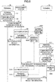
- FIG. 1 is a schematic diagram of a communication system according to an embodiment of the present invention.
- the communication system 1 is constituted with multiple communication terminals 10a, 10b, and 10c, which are, for example, video-conference terminals; multiple communication terminals 70x and 70y, which are, for example, smart phones; a communication management system 50 to manage the communication terminals; and a relay device 30.
- a "communication terminal” may be referred to as a "terminal” and a "communication management system” may be referred to as a "management system”.
- FIG. 1 illustrates the three terminals 10a, 10b, and 10c and the two terminals 70x and 70y
- the number of terminals is not limited as such.
- any one of the multiple terminals 70x and 70y may be referred to as the "terminal 70”
- any one of the multiple terminals 10a, 10b, and 10c may be referred to as the "terminal 10”.
- the terminals 10 and 70 may be general-purpose computers, electronic whiteboards, car navigation terminals, electronic signboards (digital signage), or the like that have a communication function.
- the management system 50 is a computer equipped with a server function.
- the terminals 10 and 70 are computers equipped with corresponding client functions.
- the terminals 10 and 70, the relay device 30, and the management system 50 can communicate with each other through a communication network 2, which may be constituted with the Internet, a cellular phone network, a LAN (Local Area Network), a WiFi (Wireless Fidelity) network, a Bluetooth (registered trademark) network, and the like.
- the communication network 2 also includes a base station 2a at an end of a cellular phone network. It should be noted that although only one base station 2a is illustrated in FIG. 1 , the number is not limited as such.
- the relay device 30 relays content data including sound data, video (image) data, text data, and the like between the terminals 10 and 70.
- the terminal 10 is placed in a call center, which is an example of a site, and the terminal 70 is placed at the front of a hotel, which is an example of a site.
- the management system 50, the relay device 30, and the terminals 10 and 70 are placed in the same country or area, or may be placed in different countries or areas.
- the user of the terminal 10 is, for example, an operator, and the user of the terminal 70 is, for example, a customer. It should be noted that the terminal 10 is an example of a destination terminal as a destination candidate.
- FIG. 2 is an external view of a terminal 10 according to an embodiment.
- the terminal 10 includes a housing 1100, an arm 1200, and a camera housing 1300.
- a front wall 1110 of the housing 1100 there is an air intake surface formed with a plurality of air intake holes
- a rear wall 1120 of the housing 1100 there is an air exhaust surface 1121 formed with a plurality of air exhaust holes.
- an operation panel 1150 is formed on the right wall 1130 side of the housing 1100.
- the operation panel 1150 there are a plurality of operation buttons (108a through 108e), a power supply switch 109, and an alarm lamp 119, which will be described later.
- a sound output surface 1151 is formed in the operation panel 1150, which is formed by a plurality of sound output holes used for passing output sound from a built-in speaker 115, which will be described later.
- a housing unit 1160 is formed as a concave portion for housing the arm 1200 and the camera housing 1300.
- connection ports (1132a through 1132c) are formed for electrically connecting cables for an external device connection I/F 118, which will be described later.
- a connection port is formed for electrically connecting a cable 120c of a display 120 for a display I/F 117.
- connection port 1132 an arbitrary operation button of the operation buttons (108a through 108e) will be described as an “operation button 108”, and an arbitrary connection port of the connection ports (1132a through 1132c) will be described as a "connection port 1132".
- the arm 1200 is attached to the housing 1100 via a torque hinge 1210, and is capable of rotating in an up-and-down direction within a range of tilt angle ⁇ 1 of 135 degrees with respect to the housing 1100.
- FIG. 2 illustrates a state in which the tilt angle is 90 degrees.
- the camera housing 1300 there is a built-in camera 112, which will be described later, and is capable of taking images of a user, a document, a room, and the like. Further, in the camera housing 1300, a torque hinge 1310 is formed. Further, the camera housing 1300 is attached to the arm 1200 via the torque hinge 1310.
- the camera housing 1300 is capable of rotating in a right-and-left direction within a range of +/-180 degrees of an angle ⁇ 2, and rotating in an up-and-down direction within a range of +/-45 degrees of a tilt angle ⁇ 3, with respect to the arm 1200, assuming that FIG. 2 illustrates a state in which ⁇ 2 and ⁇ 3 are zero degrees.
- the external view in FIG. 2 is merely an example, and the present embodiment is not limited to this appearance. It should be noted that description of appearance is omitted for the terminal 70, the relay device 30, and the management system 50 because these have the same appearance as a generic smart phone or a server computer.
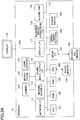
- FIG. 3A is a hardware configuration of a terminal 10 according to an embodiment.
- the terminal 10 includes a central processing unit (CPU) 101 for controlling overall operations of the terminal 10; a read-only memory (ROM) 102 in which programs used for driving the CPU 101 such as an initial program loader are stored; a random access memory (RAM) 103 that is used for a work area of the CPU 101; a flash memory 104 in which programs for the terminal 10, and various data items including image data, audio data, and the like, are stored; a solid state drive (SSD) 105 that controls writing and reading various data items to and from the flash memory 104 according to the control of the CPU 101; a media interface (I/F) 107 that controls writing and reading data to and from a recording medium 106 including a flash memory, an integrated circuit (IC) card, and the like; the operation buttons 108 operated for, for example, selecting a destination of the terminal 10; the power supply switch 109 for switching ON/OFF the power supply of the terminal 10; and a network interface (I
- the terminal 10 includes the built-in camera 112 that captures image data by taking an image of a subject according to the control of the CPU 101; an imaging element I/F 113 that controls driving the camera 112; the built-in microphone 114 for inputting sound; the built-in speaker 115 for outputting sound; a sound input/output I/F 116 for processing input/output of an audio signal between the microphone 114 and the speaker 115 according to the control of the CPU 101; the display I/F 117 for transmitting image data to the external display 120 according to the control of the CPU 101; the external device connection I/F 118 for connecting various external devices; the alarm lamp 119 for indicating an error of various functions of the terminal 10; and a bus line 110 such as an address bus, a data bus, and the like, for electrically connecting the above elements as illustrated in FIG. 3 .
- a bus line 110 such as an address bus, a data bus, and the like, for electrically connecting the above elements as illustrated in FIG. 3 .
- the display 120 is a display unit used for displaying a subject image or the like. Examples of the display 120 include a liquid crystal and an organic electroluminescence (EL) panel. Further, the display 120 is connected to the display I/F 117 via the cable 120c.
- the cable 120c may be a cable for an analog RGB (VGA) signal, a cable for a component video, or a cable for a signal of High-Definition Multimedia Interface (HDMI) (registered trademark) or Digital Video Interactive (DVI).
- VGA analog RGB
- HDMI High-Definition Multimedia Interface
- DVI Digital Video Interactive
- the camera 112 includes a lens and a solid-state image sensing device to convert light into electric charge for computerizing the subject image, and as the solid-state image sensing device, a Complementary Metal Oxide Semiconductor (CMOS), a Charge Coupled Device (CCD), or the like, is used.
- CMOS Complementary Metal Oxide Semiconductor
- CCD Charge Coupled Device
- USB Universal Serial Bus
- the recording medium 106 can be easily attached or detached with the terminal 10. Further, as a non-volatile memory to/from that data are written/read according to the control of the CPU 101, an Electrically Erasable and Programmable ROM (EEPROM) may be used, not limited to the flash memory 104.
- EEPROM Electrically Erasable and Programmable ROM
- FIG. 3B is a block diagram illustrating a hardware configuration of the terminal 70.
- the terminal 70 includes a CPU 701 to control operations of the terminal 70 as a whole; a ROM (Read-Only Memory) 702 to store programs; a RAM 703 used as a work area of the CPU 701; an EEPROM (Electrically Erasable and Programmable ROM) 704 on which data read and write are executed according to the control of the CPU 701; a media I/F 707 to control data read and write (storing) on a recording medium 706 such as a flash memory or the like; and a CMOS (Complementary Metal Oxide Semiconductor) sensor 712 to capture a photographic subject according to the control of the CPU 701.
- CMOS Complementary Metal Oxide Semiconductor
- the EEPROM 704 stores various data items including an operating system (OS) executed by the CPU 701 and other programs.
- the CMOS sensor 712 is a charge-coupled device that converts light into electric charge to computerize an image of a photographic subject.
- the CMOS sensor may be replaced with a CCD (Charge Coupled Device) sensor as long as a photographic subject can be captured.
- CCD Charge Coupled Device
- the terminal 70 further includes a microphone 714 to convert a sound into a sound signal; a speaker 715 to convert a sound signal into a sound; an antenna 711a; a communicator 711 to communicate with a nearby base station 2a by a wireless communication signal by using the antenna 711a; a display 720 of liquid crystal, organic EL, or the like to display images of photographic subjects, various icons, and the like; a touch panel 721 that is installed on this display 720, and constituted with a pressure-sensitive or electrostatic panel, to detect a touch position on the display 720 touched with a finger, a touch pen, or the like; and a bus line 710 such as an address bus, a data bus, etc., for electrically connecting the above elements.
- a microphone 714 to convert a sound into a sound signal
- a speaker 715 to convert a sound signal into a sound
- an antenna 711a to convert a nearby base station 2a by a wireless communication signal by using the antenna 711a
- FIG. 4 is a hardware configuration diagram of a management system 50 according to an embodiment.
- the management system 50 includes a CPU 201 for controlling overall operations of the management system 50; a ROM 202 in which programs used for driving the CPU 201 such as an IPL are stored; a RAM 203 that is used for a work area of the CPU 201; an HD 204 for storing various data items including programs for the management system 50, and the like; a hard disk drive (HDD) 205 for controlling various data reading and data writing of the HD 204 according to the control of the CPU 201; a medium I/F 207 for controlling data reading and data writing (storage) of a recording medium 206 including a flash memory; a display 208 for displaying various information items including a cursor, a menu, a window, a character, or an image; a network I/F 209 for performing data communication by using the communication network 2; a keyboard 211 including a plurality of keys for inputting characters, numerical values, various instructions, and the like; a
- the relay apparatus 30 has a similar hardware configuration as the above management system 50, and thus, the descriptions will be omitted.
- FIG. 5A is a block diagram illustrating a software configuration of the terminal 10 according to an embodiment.
- the terminal 10 has a "communication application A1" installed as a client application.
- an OS 1020 and a communication application A1 run on a work area 1010 in the RAM 103 of the terminal 10.
- the OS 1020 is basic software that provides basic functions to manage the terminal 70 as a whole.
- the communication application A1 is an application for communicating with the other terminals. It should be noted that the communication application A1 and the OS 1020 are installed in each of the terminals 10 that constitutes the communication system 1 in the present embodiment.
- FIG. 5B is a block diagram illustrating a software configuration of the terminal 70 according to an embodiment.
- the terminal 70 has a "communication application A7" installed as a client application.
- an OS 7020 and the communication application A7 run on a work area 7010 in the RAM 703.
- the OS 7020 is basic software that provides basic functions to manage the terminal 70 as a whole.
- the communication application A7 is an application for communicating with the other terminals. It should be noted that the communication application A7 and the OS 7020 are installed in each of the terminals 70 that constitutes the communication system 1 in the present embodiment.
- SIP Session Initiation Protocol
- H.323 a protocol that enhances SIP
- (4) a protocol of Instant Messenger (5) a protocol using MESSAGE method of SIP
- (6) a protocol of Internet Relay Chat (IRC); and (7) a protocol that enhances the protocol of Instant Messenger.
- (4) a protocol of Instant Messenger is a protocol used in, for example, (4-1) XMPP (Extensible Messaging and Presence Protocol); or (4-2) ICQ (registered trademark), AIM (registered trademark), Skype (registered trademark), and the like.
- (7) a protocol that enhances the protocol of Instant Messenger is, for example, Jingle.
- FIG. 6 is a block diagram illustrating functions (elements) of terminals 10, 70, and the management system 50 included as a part of the communication system 1 according to the present embodiment. It should be noted that in FIG. 6 , the terminals 10, 70, and the management 50 are connected to perform data communication via the communication network 2.
- the management system 50 manages communication between the terminal (communication terminal) 70 and the terminal (destination terminal) 10.
- the terminals 10 and 70 include the sending and receiving units 11 and 71, the operation input receiving units 12 and 72, the activation units 13 and 73, the output control units 14 and 74, and the storing and reading units 19 and 79, respectively.
- the terminal 70 also includes the state management unit 75. These units are functions realized by the elements illustrated in FIG. 3 that operate according to instructions from the CPU 101 or 701 to execute an application (program) read from the flash memory 104 or the EEPROM 704 and loaded on the RAM 103 or 703.
- the terminal 10 includes a memory unit 1000 or 7000 constituted with the ROM 102 or 702, the RAM 103 or 703, and the flash memory 104 or the EEPROM 704 illustrated in FIG. 3 .
- FIG. 7A is a schematic view illustrating a destination management table. It should be noted that a destination management table in FIG. 7A represents a state when a presence management table is in a state of Table 3, which will be described later.
- a destination management DB 7001 is constituted with a destination management table as illustrated in FIG. 7A .
- the communication ID of a terminal 10 of an operator, which is a destination candidate; a presence that represents a state of the destination candidate; and attribute information that represents attributes of this destination candidate are associated with each other, to be managed. Specifically, as illustrated in FIG.
- the communication ID of "O01" of the terminal 10a is associated with "Chat” that represents that the terminal 10a is in a state of communicating with the other terminals, and attributes of "en, zh, es".
- the communication ID of "O02" of the terminal 10b is associated with "Online” that represents that the terminal 10b is in a state of being ready to start communicating with the other terminals, and attributes of "en, es, pt, ru, th”.
- the communication ID of "O03" of the terminal 10c is associated with "Offline” that represents that the terminal 10c is not in a state of being ready to start communicating with the other terminals, and attributes of "ko, pt”.
- the communication ID is information for identifying a communication destination (communication counterpart) in the communication system 1.
- the communication ID is not limited specifically, and may be identification information of a terminal 10, identification information or an account of a user of the terminal 10, or the like. It should be noted that "presence" will be described in detail later.
- FIG. 7B is a schematic view illustrating a presence management table.
- a presence management DB 7002 is constituted with a presence management table as illustrated in FIG. 7B .
- attribute information that represents an attribute of a destination candidate; presence information that represents a presence of a group of destination candidates having the attribute; communication IDs of terminals 10 having the presence of "Online” among the destination candidates having the attribute; and communication IDs of terminals 10 having the presence of "Chat” among the destination candidates having the attribute are associated with each other, to be managed.
- each attribute is associated with a presence of a group representing whether at least one of terminals (destination candidates) 10 among one or more terminals (destination candidates) 10 associated with the attribute is in a state of being ready to start communication.
- the sending and receiving unit 11 is implemented by instructions from the CPU 101, and the network I/F 111.
- the sending and receiving unit 71 is implemented by instructions from the CPU 701, and the communicator 711.
- the sending and receiving units 11 and 71 execute sending and receiving various data (or information) items to and from a terminal, an apparatus, a system, and the like, as communication counterparts, via the communication network 2.
- the operation input receiving unit 12 is implemented by instructions from the CPU 101, the operation buttons (108a, 108b, 108c, 108d, and 108e), and the power supply switch 109.
- the operation input receiving unit 72 is implemented by instructions from the CPU 701, and the touch panel 721.
- the operation input receiving units 12 and 72 receive various inputs or various selections performed by the user.
- the activation units 13 and 73 are implemented by instructions from the CPUs 101 and 701, to activate operations of the communication applications A1 and A7, respectively.
- the output control units 14 and 74 are implemented by instructions from the CPUs 101 and 701, respectively, along with the display I/F 117 and the sound input and output I/F 116, to control outputting image data and sound data.
- the state management unit 75 of the terminal 70 is implemented by instructions from the CPU 701, to manage a state of a destination candidate based on presence information transmitted from the terminal 10 to the terminal 70.
- the storing and reading units 19 and 79 are implemented by instructions from the CPUs 101 and 701, to execute storing various data items in the memory units 1000 and 7000 and reading various data items stored in the memory units 1000 and 7000, respectively.
- the management system 50 includes a sending and receiving unit 51, an authentication unit 52, a management unit 53, a session control unit 58, and a storing and reading unit 59. These units are functions realized by the elements illustrated in FIG. 4 that operate according to instructions from the CPU 201 to execute a program for the management system 50 read from the HD 204 and loaded on the RAM 203. Further, the management system 50 includes a memory unit 5000 constituted with the HD 204. Furthermore, the memory unit 5000 includes databases (DBs) constituted with respective tables as described below.
- DBs databases
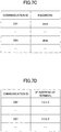
- FIG. 7C is a schematic view illustrating an authentication management table.
- an authentication management DB 5001 is constituted with the authentication management table as illustrated in FIG. 7C .
- the communication ID is associated with a password for authentication, and stored to be managed.
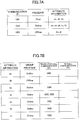
- FIG. 7D is a schematic view illustrating a terminal management table.
- a terminal management DB 5002 is constituted with a terminal management table as illustrated in FIG. 7D .
- the communication ID is associated with an IP address of the terminal 10 or 70, and stored to be managed.
- the sending and receiving unit 51 is implemented by instructions from the CPU 201, and the network I/F 209, and performs sending and receiving various data (or information) items to and from a terminal, an apparatus, and/or a system via the communication network 2.
- the authentication unit 52 is implemented by instructions from the CPU 201, searches in the authentication management table by using a communication ID and a password received by the sending and receiving unit 51 as the search key, and determines whether the same communication ID and password are managed in the authentication management table, to authenticate a terminal.
- the management unit 53 is implemented by instructions from the CPU 201, and in the terminal management table (see FIG. 7D ), manages terminals 10 currently logged in.
- the session control unit 58 controls a session for sending and receiving content data between the terminals 10 and 70, by instructions from the CPU 201.
- the control includes establishing a session, controlling the terminal 10 or 70 to participate in an established session and to exit from the session, and the like.
- the storing and reading unit 59 is implemented by instructions from the CPU 201 and the HDD 205, or implemented by instructions from the CPU 201.
- the storing and reading unit 59 stores various data items in the memory unit 5000, and extracts various data items stored in the memory unit 5000.
- FIG. 8 is a sequence chart illustrating a process in which terminals 10 and 70 log in to the management system 50.
- the operation input receiving unit 72 receives the power-on operation, and activates the terminal 70 (Step S1).
- the activation unit 73 activates the communication application A7 installed in the terminal 70 (Step S2). Thereafter, a process in the terminal 70 is executed by instructions of the communication application A7.
- the sending and receiving unit 71 of the terminal 70 transmits a login request to the management system 50 through the communication network 2 (Step S3).
- This login request includes the communication ID and a password for identifying the terminal itself (terminal 70), which is the login requestor.
- a communication ID of a terminal 70 starts with a character "C" so that it can be distinguished as a terminal 70 on the customer side.
- communication IDs of the terminals 70x and 70y are "C01, C02".
- the sending and receiving unit 51 of the management system 50 receives a login request.
- the management system 50 on the receiving side can obtain the IP address of the terminal 70 on the sending side.
- the authentication unit 52 of the management system 50 searches in the authentication management table (see FIG. 7C ) in the memory unit 5000, by using the communication ID and password included in the login request as the search key, and determines whether the same communication ID and password are managed in the authentication management table, for authentication (Step S4).
- the session management unit 53 associates the communication ID with the IP address of the terminal 70, and stores it in the terminal management table (see FIG. 7D ) (Step S5). Thereby, the terminal control table manages information for accessing to the logged-in terminal 70.
- the sending and receiving unit 51 of the management system 50 transmits authentication result information that represents an authentication result obtained by the authentication unit 52, to the terminal 70 as the login requestor via the communication network 2 (Step S6).
- the sending and receiving unit 71 of the terminal 70 receives the authentication result information.
- a case will be described in which authentication of the terminals 70x and 70y as login requestors has succeeded, and the terminals 70x and 70y have logged in to the management system 50.
- the operation input receiving unit 12 receives the power-on operation, and activates the terminal 10 (Step S11).
- the activation unit 13 activates the communication application A1 installed in the terminal 10 (Step S12). Thereafter, a process in the terminal 10 is executed by instructions of the communication application A1.
- the output control unit 14 of the terminal 10 outputs a reception screen that receives input (designation) of one or more attributes of the operator as the user of the terminal 10 to the display 120.
- FIG. 9 is a diagram illustrating an example of a reception screen.
- the reception screen 140 includes fields to receive input of a communication ID and a password, and in addition, options of available languages and check boxes for selection as attributes of the operator. Once the operator has selected one or more options of the available languages, and performs an operation to press the OK button on the reception screen 140, the operation input receiving unit 12 receives input of the attributes of the operator (Step S13-1).
- the storing and reading unit 19 causes the storage unit 1000 to store attribute information corresponding to the selected attributes.
- attribute information corresponding to the available languages "English, Chinese, Korean, Portuguese, Spanish, Thai, and Russian” are denoted as "en, zh, ko, pt, es, th, and ru", respectively. It should be noted that in the example illustrated in FIG. 9 , English, Chinese, and Spanish are selected as the attributes associated with the terminal 10, which are available languages (usable languages) with the operator.
- the terminal 10 transmits a login request to the management system 50, and logs in to the management system 50 (Steps S13-2, S14, S15, and S16). Since this process is the same as the process of Steps S3, S4, S5, and S6 between the terminal 70 and the management system 50, description is omitted. However, a communication ID of a terminal 10 transmitted from a terminal 10 to the management system 50 starts with a character "O" so that it can be distinguished as a terminal 10 on the operator side. In the following, assume that communication IDs of the terminals 10a, 10b, and 10c are "O01, O02, and O03", respectively. Once authentication of the terminals 10a, 10b, and 10c as login requestors has succeeded, the terminals 10a, 10b, and 10c log in to the management system 50.
- FIG. 10 is a sequence chart illustrating a process of transmitting presence information.
- the communication application A1 manages, in the storage unit 1000, an event that causes a state transition, and a presence after the transition caused by the event.
- the presence is used for identifying whether the operator as the user of the terminal 10 is in a state of being ready for a call.
- a presence that represents a state of being ready for a call includes "Online” that represents a state where the terminal 10 has logged in to the management system 50, and does not communicate with the terminal 70 on the customer side.
- a presence that represents a state of being not ready for a call includes "Offline” that represents a state where the terminal 10 does not log in to the management system 50, and "chat” that represents a state where the terminal 10 has logged in to the management system 50, but has already communicated with the terminal 70 on the customer side, and hence, cannot newly start communication.
- the presence in the present embodiment any information usable for identifying whether it is a state of being ready for a call may be used, which is not limited to the one described above.
- the presence may also include something based on input from the user. Among the presence based on input from the user, as an example of a presence that represents a state of being not ready for a call, "away from the seat” may be considered.
- an event that causes a transition to the presence of "Online” reception of authentication result information by the terminal 10 at Step S16, a reception of input of an end request for a call from the user, or the like may be considered.
- an event that causes a transition to the presence of "Offline” a logout from the management system 50 by the terminal 10 may be considered.
- an event that causes a transition to the presence of "chat” establishment of communication between the terminal 70 and the terminal 10 (at Step S90, as will be described later) may be considered. It should be noted that these events and presences are merely examples and the embodiment is not limited as such. It should be noted that the event that causes a transition of the presence is not limited in particular as long as it is detectable, and can be set discretionarily depending on content of a process executed by a communication protocol or the communication application A1.
- the storing and reading unit 19 reads attribute information, for example, "en, zh, es" from the storage unit 1000.
- the attribute information to be read corresponds to the attributes of "English, Chinese, and Spanish" or the like that has been input by the operator as the user of the terminal 10a when logging in (see Step S13-1).
- the sending and receiving unit 11 of the terminal 10a transmits the presence that represents a state after the transition caused by the event at Step S21, the attribute information read from the storage unit 1000, and the presence information that includes the communication ID of "O01" of the terminal 10a as the transmission source to the management system 50 (Step S22).
- the terminal 10a transmits presence information including the presence of "Online” to the management system. Also, upon acceptance of a logout request, the terminal 10a transmits presence information including the presence of "Offline” to the management system 50. Also, in response to establishment of communication with the terminals 70, the terminal 10a transmits presence information including the presence of "chat” to the management system 50. It should be noted that if the attribute information has not been updated since the attribute information was registered in the storage unit 1000 at Step S13-1, the terminal 10a transmits presence information including the same attribute information to the management system 50 every time an event occurs.
- the sending and receiving unit 51 of the management system 50 transmits the received presence information to the terminals 70x and 70y on the customer side that have logged in to the management system 50 (Steps S23 and S24).
- a method of identifying a terminal 70 on the customer side that has logged in to the management system 50 is not limited in particular. As an example, a method may be considered that reads a communication ID starting with the character "C" from the terminal management table (see FIG. 7D ).
- the sending and receiving unit 71 of each of the terminals 70x and 70y receives the presence information transmitted from the terminal 10a on the operator side through the management system 50.
- the storing and reading unit 79 of each of the terminals 70x and 70y records the communication ID, the presence, and the attribute information included in the received presence information in the destination management table (see FIG. 7A ) (Steps S25 and S26). In the case where a record that includes the same communication ID as included in the received presence information exists in the destination management table, the storing and reading unit 79 overwrites and updates this record based on the newly received presence information. Thereby, the terminals 70x and 70y can manage the latest presence on the side of the terminal 10a.
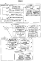
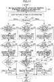
- FIG. 11 is a flowchart illustrating a process of managing presence for each attribute.
- the group presence of "Online” represents that one of destination candidates of the group having this attribute has the presence of "Online” representing that it is ready for a call.
- the group presence of "Chat” represents that no destination candidate of the group is in a state of the presence of "Online”, and one or more destination candidates have the presence of "Chat” representing an in-call state.
- the group presence of "Offline” represents that all destination candidates of the group having this attribute have the presence of "Offline”.
- an example of a process of determining the group presence will be described. It should be noted that in the following, although the process will be described with the terminal 70x, substantially the same process can be executed with the terminal 70y.
- the state management unit 75 of the terminal 70x obtains information recorded in the updated record (Step S51).
- the obtained information includes the communication ID of the terminal 10 as the transmission source, the presence that represents the latest states of destination candidates, and the attribute information that represents the attributes of the destination candidates.
- the state management unit 75 of the terminal 70x updates each record that includes the attribute information obtained at Step S51 in the presence management table. In other words, in the case where the obtained attribute information is "en, zh, es", the state management unit 75 updates each record that includes the attribute information of "en, zh, es".
- the state management unit 75 of the terminal 70x refers to the ready-for-call field in the record in which the attribute information of "en” is recorded in the presence management table (see FIG. 7B ). Thereby, the state management unit 75 determines whether the communication ID of "O01" obtained at Step S51 is included in the ready-for-call field (Step S53).
- the state management unit 75 adds the obtained communication ID of "O01" to the ready-for-call field (Step S54).
- Step S54 the state management unit 75 of the terminal 70x refers to the in-call field in the record in which the attribute information of "en” is recorded in the presence management table (see FIG. 7B ). Thereby, the state management unit 75 determines whether the communication ID of "O01" obtained at Step S51 is included in the in-call field (Step S55). In the case of having determined that the communication ID of "O01" obtained at Step S51 is included in the in-call field in the presence management table (YES at Step S55), the state management unit 75 deletes the obtained communication ID of "O01” from the in-call field (Step S56).
- the process executed up to here enables, in the case where the presence on the side of the terminal 10a transitions from “Chat” to “Online”, and in the case of transitioning from "Offline” to “Online", the communication ID of the terminal 10a only in the ready-for-call field in the record in which the attribute information of "en” is recorded in the presence management table.
- Step S56 the state management unit 75 of the terminal 70x refers to the group presence in the record in which the attribute information of "en” is recorded in the presence management table (see FIG. 7B ). Thereby, the state management unit 75 determines whether the group presence is "Online” (Step S57).
- the state management unit 75 updates this presence to "Online”. In the case of having determined that the group presence in the record in which the attribute information of "en” is recorded is "Online” (YES at Step S57), the state management unit 75 does not update the group presence in the record in which the attribute information of "en” is recorded.
- the process executed up to here causes the group presence in the record in which the attribute information of "en” is recorded in the presence management table to transition to "Online”.
- the state management unit 75 applies the loop process to each record in which the attribute information of "zh, es" is recorded in the presence management table, to update the records similarly.
- the presence management table in FIG. 7A becomes as illustrated in Table 1.
- the presence management table of each terminal 70 is updated such that the communication ID of "O01” is added to the ready-for-call field corresponding to the attribute of "en, zh, es" associated with the communication ID of "O01" of the terminal 10a.
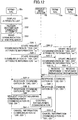
- the state management unit 75 of the terminal 70x refers to the ready-for-call field in the record in which the attribute information of "en” is recorded in the presence management table (see Table 1). Thereby, the state management unit 75 determines whether the communication ID of "O01" obtained at Step S51 is included in the ready-for-call field (Step S63). In the case of having determined that the communication ID of "O01" obtained at Step S51 is included in the ready-for-call field in the presence management table (YES at Step S63), the state management unit 75 deletes the obtained communication ID from the ready-for-call field (Step S64).
- Step S64 the state management unit 75 of the terminal 70x refers to the ready-for-call field in the record in which the attribute information of "en” is recorded in the presence management table (see Table 1). Thereby, the state management unit 75 determines whether the communication ID of "O01" obtained at Step S51 is included in the in-call field (Step S65). In the case of having determined that the communication ID of "O01" obtained at Step S51 is not included in the in-call field in the presence management table (NO at Step S65), the state management unit 75 adds the obtained communication ID of "O01" to the in-call field (Step S66).
- the process executed up to here enables to record the communication ID of the terminal 10a only in the in-call field in the record in which the attribute information of "en” is recorded in the presence management table.
- Step S66 the state management unit 75 of the terminal 70x refers to the ready-for-call field in the record in which the attribute information of "en” is recorded in the presence management table (see Table 1). Thereby, the state management unit 75 determines whether the number of communication IDs currently recorded in the ready-for-call field in the record in which the attribute information of "en” is recorded is 0 (Step S67).
- the state management unit 75 updates the group presence in the record in which the attribute information of "en” is recorded to "Chat” (Step S68). In the case where the number of communication IDs currently recorded in the ready-for-call field in the record in which the attribute information of "en” is recorded is not 0 (NO at Step S67), the state management unit 75 does not update the group presence in the record in which the attribute information of "en” is recorded. In other words, in the case where a communication ID is recorded in the ready-for-call field in the record in which the attribute information of "en” is recorded, the corresponding presence is not updated so as to be maintained as "Online”.
- the state management unit 75 applies the loop process to each record in which the attribute information of "zh, es" is recorded in the presence management table, to update the records similarly.
- the presence management table of Table 1 becomes as illustrated in Table 2.
- the presence management table of each terminal 70 is updated such that the communication ID of "O01” is added to the in-call field corresponding to the attribute of "en, zh, es" associated with the communication ID of "O01" of the terminal 10a.
- the state management unit 75 of the terminal 70x refers to the ready-for-call field in the record in which the attribute information of "ko" is recorded in the presence management table (see Table 2). Thereby, the state management unit 75 determines whether the communication ID of "O03" obtained at Step S51 is included in the ready-for-call field (Step S73).
- the state management unit 75 deletes the obtained communication ID of "O03" from the ready-for-call field (Step S74).
- Step S74 the state management unit 75 of the terminal 70x refers to the in-call field in the record in which the attribute information of "ko" is recorded in the presence management table (see Table 2).
- the state management unit 75 determines whether the communication ID of "O03" obtained at Step S51 is included in the in-call field (Step S75).
- the state management unit 75 deletes the obtained communication ID of "O03" from the in-call field (Step S76).
- the process executed up to here causes the communication ID of the terminal 10c to be deleted from the record in which the attribute information of "ko" is recorded in the presence management table.
- Step S76 the state management unit 75 of the terminal 70x refers to the ready-for-call and in-call fields in the record in which the attribute information of "ko" is recorded in the presence management table (see Table 2). Thereby, the state management unit 75 determines whether a condition IF1 or IF2 is satisfied (Step S77).
- the condition IF1 represents a case where the number of communication IDs currently recorded in the ready-for-call field is 0, and the number of communication IDs currently recorded in the in-call field is not 0, in the record in which the attribute information of "ko" is recorded.
- the condition IF2 represents a case where the number of communication IDs currently recorded in the ready-for-call field is 0, and the number of communication IDs currently recorded in the in-call field is 0, in the record in which the attribute information of "ko" is recorded.
- the state management unit 75 updates the group presence to "Chat” in the record in which the attribute information of "ko" is recorded in the presence management table (Step S78).
- the state management unit 75 updates the group presence to "Offline” in the record in which the attribute information of "ko" is recorded in the presence management table (Step S79). In the case where neither IF1 nor IF2 is satisfied at Step S77 (NO at Step S77), the state management unit 75 does not update the group presence so as to maintain "Online” in the record in which the attribute information of "ko" is recorded.
- the state management unit 75 applies the loop process to the record in which the attribute information of "pt” is recorded in the presence management table, to update the record similarly.
- the presence management table of Table 2 becomes as illustrated in Table 3.
- the presence management table of each terminal 70 is updated such that the communication ID of "O03" is deleted from the ready-for-call field corresponding to the attribute of "ko, pt" associated with the communication ID of "O03" of the terminal 10c.
- FIG. 12 is a sequence chart illustrating a process of starting communication.
- the terminal 70x starts communication
- the terminal 70y can also start communication by substantially the same process.
- the operation input receiving unit 12 of the terminal 70x receives a display request of an attribute list of destination candidates in response to an input operation by the user.
- the output control unit 74 obtains attribute information items currently recorded in the presence management table (see Table 3), and the group presence corresponding to the attribute information items.
- the output control unit 74 obtains information that represents, for each attribute, which terminal (destination candidate) is in a state of "Online” or ready to start communication among one or more terminals (destination candidates) 10 associated with the attribute.
- the storage unit 7000 stores in advance data of display images corresponding to attribute information items, and display images corresponding to the group presence. For example, data of a display image corresponding to the attribute information of "en” is text data that represents "English".
- data items of display images corresponding to the group presence of "Online, Offline, and Chat" are image data items of icons representing a check mark, a blank image, and a bubble, respectively.
- the output control unit 74 obtains, for each pair of an obtained attribute information item and a group presence, a corresponding pair of data items of a text and a display image of an icon, from a storage unit 7000.
- the output control unit 74 generates image data of an attribute list by arranging the obtained pairs of data items of display images such that the items in each pair are located on the same row in a predetermined display area.
- the output control unit 74 outputs the generated image data of the attribute list to the display 720 (Step S81).
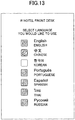
- FIG. 13 is a diagram illustrating an example of an attribute list displayed in the case where the presence management table is in the state of Table 3.
- the output control unit 74 repeatedly executes the above process every time the presence management table is updated. Thereby, an attribute list indicating the latest group presence for the respective attributes is displayed on the display 720.
- the output control unit 74 outputs an icon presenting a check mark corresponding to "Online” as a selectable icon, and an icon presenting a blank image or a bubble corresponding to "Offline, Chat” as a non-selectable icon, among the icons. For example, even if the user performs an operation of pressing an icon of a blank image corresponding to "Korean” or an icon presenting a bubble corresponding to "Chinese” in the attribute list illustrated in FIG. 13 , the operation input receiving unit 72 does not receive the input operation.
- the output control unit 74 may output a message stating that a call cannot be readily started or a message suggesting a wait for a timing to start a call to the display 720.
- the output control unit 74 can refer to the presence management table illustrated in Table 3, to display a screen as illustrated in FIG. 13 on the display 720.
- the output control unit 74 displays messages (items) that represent the attributes of English, Chinese, Korean, Portuguese, Spanish, Thai, and Russian, and icons (items) that represent the group presence corresponding to the respective attributes.
- the output control unit 74 displays an icon that represents a group presence associated with a message that corresponds to the attribute.
- the icons that represent the group presence represent whether one of terminals 10 among the terminals 10 associated with the attributes can start communication.
- Step S82 the operation input receiving unit 72 receives a selection of the attribute corresponding to the icon. For example, if an icon of a check mark corresponding to the display of English is pressed, the operation input receiving unit 72 receives "English” as a destination candidate attribute.
- the storing and reading unit 79 uses the attribute information of "en” that represents the attribute selected at Step S82 as the search key, to search in the destination management table (see FIG. 7A ) so as to read corresponding pairs of communication IDs and presences (Step S83). For example, in the case where attribute information that represents the attribute selected at Step S82 is "en”, a pair of "O01, Chat” and a pair of "O02, Online” are read from the destination management table in FIG. 7A as pairs of communication IDs and presences (statuses).
- the sending and receiving unit 71 of the terminal 70x transmits to the management system 50 a start request for a call that includes, among the communication IDs read at Step S83, the communication ID of "O02" having the presence of “Online”, the communication ID of "C01” of the terminal 70x as the start requestor, and the attribute information of "en” representing the attribute selected at Step S82 (Step S84-1).
- the sending and receiving unit 51 of the management system 50 transmits this start request for a call to the terminal 10b identified by the communication ID of "O02" included in the start request for a call (Step S84-2).
- the sending and receiving unit 51 transmits a request for starting communication to one or more terminals 10 in states of being ready to start communication among the terminals 10 associated with an attribute selected by the user of the terminal 70x.
- the terminal 70x During a period after having transmitted the start request for a call, and before receiving a response, in the case where the destination management table is updated at Step S26, S36, or S46, the terminal 70x repeatedly executes Step S83. Thereby, in the case where the presence on the side of the terminal 10a is updated to "Online", and the communication ID of "O01" is extracted as a communication ID having the corresponding presence of "Online", the sending and receiving unit 71 of the terminal 70x transmits a start request for a call including the communication ID of "O01" to the management system 50 (Step S85-1). It should be noted that the start request for a call transmitted here also includes the attribute information of "en” that represents the attribute selected at Step S82, and the communication ID of "C01" of the terminal itself (terminal 70x).
- the sending and receiving unit 51 of the management system 50 transmits this start request of a call to the terminal 10a identified by the communication ID of "O01" included in the received start request of a call (Step S85-2).
- the sending and receiving unit 11 of each of the terminals 10a and 10b receives the start request for a call transmitted from the terminal 70x through the management system 50.
- the output control unit 14 of each of the terminals 10a and 10b outputs a message that includes information of the requestor corresponding to the communication ID of "CO1" included in the start request for a call, and information of an attribute corresponding to the attribute information of "en” included in the start request for a call, to the display 120.
- FIG. 14 is an example of a message displayed on the display 120. Presenting an attribute in a message enables the operator as the user of the terminal 10 to grasp in advance which language is to be used in a call before starting the call.
- the message in FIG. 14 includes a response button for receiving permission to start a call.
- the operation input receiving unit 12 receives it as an input operation of permission of a response (Steps S86-1 and S86-2).
- the sending and receiving unit 11 of each of the terminals 10a and 10b transmits response information that includes the communication ID of "C01" of the start requestor of a call, and the communication ID of "O01 or O02" of the terminal 10a or 10b itself, to the management system 50 (Steps S87-1 and S87-2).
- the sending and receiving unit 11 of the terminal 10 may automatically transmit a response to the start request to the terminal 70. Also, in the case of receiving multiple start requests for a call by multiple terminals 70, the sending and receiving unit 11 of the terminal 10 may transmit response information to a terminal 70 from which the request was received first among the requestors of the start requests.
- the sending and receiving unit 51 of the management system 50 receives the response information transmitted by the terminal 10a, and the response information transmitted by the terminal 10b.
- the sending and receiving unit 51 of the management system 50 transmits the received response information to the terminal 70x identified by the communication ID of "C01" included in the response information (Steps S87-2 and S88-2) .
- the sending and receiving unit 71 of the terminal 70x transmits a communication establishment request for establishing communication with a terminal 10 as the transmission source of the response information, to the management system 50 (Step S89).
- the communication establishment request includes the communication ID of the terminal itself (terminal 70x), and the communication ID of the terminal 10 as the transmission source of the response.
- the sending and receiving unit 71 of the terminal 70x includes the communication ID of "O02" of the terminal 10b as the first transmission source of the response information in the communication establishment request.
- the terminal 70x in the case where the sending and receiving unit 71 of the terminal 70x has transmitted communication start requests to the terminals 10a and 10b among destination candidates in states of being ready to start communication, and responses to the communication start request are transmitted to the terminal 70x from both the terminal 10a and the terminal 10b, the terminal 70x establishes communication with the terminal 10b that transmitted the first-received response.
- the sending and receiving unit 71 of the management system 50 receives the communication establishment request.
- the session control unit 58 of the management system 50 executes control of establishing a session for transmitting content data including image data and sound data through the relay device 30 between the terminal 10b and the terminal 70x identified by the communication IDs of "O02, C01" included in the communication establishment request (Step S90).
- the session is not limited as above, and may be a session for transmitting content data directly between the terminal 10b and the terminal 70x through the communication network 2.
- each of the terminal 10b and the terminal 70x transmits image data of an image captured at the terminal itself, and sound data collected at the terminal itself to the terminal on the other side through the relay device 30.
- the output control units 14 and 74 of the terminals 10b and 70x output received content data, respectively. Thereby, the users can start a call.
- the sending and receiving unit 11 of the terminal 10b transmits the presence of "Chat”, the attribute information of "en, es, pt, ru, th", and the presence information including the communication ID of "O02", to the management system 50 (see Step S22).
- the sending and receiving unit 71 of the terminal 70x transmits cancellation information to the management system 50 (Step S91-1).
- the cancellation information includes the communication ID of "C01" of the terminal itself (terminal 70x), and the communication ID of "O01" of the terminal 10a as the transmission source of a response other than the transmission source from which the response was received first.
- the sending and receiving unit 51 of the management system 50 transmits the cancellation information to the terminal 10a identified by the communication ID of "O01" included in the cancellation information (Step S91-2).
- the sending and receiving unit 11 of the terminal 10a receives the cancellation information transmitted by the management system 50. This enables the user on the side of the terminal 10a to grasp that the response to the start request for a call from the terminal 70x has become unnecessary.
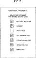
- FIG. 15 is an example of a display of an attribute list in the second embodiment (see Step S81).
- the terminal 10 in the second embodiment is suitably used by a reception in a general hospital that covers multiple subjects of medical treatment.
- the terminal 70 in the second embodiment is suitably used by a patient of such a general hospital.
- attributes are not limited to those in the above embodiments, and can be selected discretionarily.
- the names of places such as “New York, London, Tokyo”, and the like to designate travel destinations, locations of real estate, and the like, and "food, clothing, household appliance”, and the like to designate types of goods, are exemplified.
- the external device connection I/F 118 of a terminal 10 is connected to a headset having a microphone and a speaker built-in.
- the output control unit 14 of the terminal 10 further generates a screen for receiving a selection of sound input and output devices to be used when receiving a call and during the call, and outputs the screen to the display 120.
- FIG. 16 is an example of a screen for receiving a selection of sound input and output devices.
- the operation input receiving unit 12 of the terminal 10 receives a selection of sound input and output devices to be used when receiving a call and during a call at Step S13-1. Identification information of the selected sound input and output devices is stored in the storage unit 1000 by the storing and reading unit 19.
- the output control unit 14 refers to the identification information of a sound output device to be used when receiving a call that is stored in the storage unit 1000, and causes the sound output device identified by this identification information to sound a ringtone.
- the sending and receiving unit 11 of the terminal 10 receives sound data transmitted from the terminal 70.
- the output control unit 14 of the terminal 10 refers to the identification information of a sound output device to be used during a call that is stored in the storage unit 1000, and causes the sound output device identified by this identification information to sound a ringtone.
- the sending and receiving unit 11 of the terminal 10 refers to the identification information of a sound input device to be used during a call that is stored in the storage unit 1000, and transmits sound data input from the sound input device identified by this identification information to the terminal 70. The above process enables to appropriately switch sound input and output devices to be used depending on timings.
- the sending and receiving unit 71 (an example of an obtainer) of the terminal 70 receives attribute information that represents attributes of respective destination candidates, and presence (an example of state information) that indicates whether each of the destination candidates is in a state of being ready to start a call (an example of communication), to obtain the attribute information and the presence (see Steps S24, S34, and S35) (an example of obtaining).
- the sending and receiving unit 71 obtains the attribute information that represents, for each destination candidate, one or more attributes of the destination candidate, and a state information that indicates, for each of the destination candidates, whether the destination candidate is in a state of being ready to start communication.
- the state management unit 75 (an example of a determiner) of the terminal 70 determines whether the group presence of the destination candidates of the attribute indicated by this attribute information is "Online" (see Step S51 or S79) (an example of determining). In other words, the state management unit 75 determines for every attribute whether it is in a state where one of destination candidates can start communication among one or more destination candidates associated with the attribute. It should be noted that the group presence of "Online" represents that one of destination candidates having this attribute is ready for a call.
- the output control unit 74 (an example of a display controller) of the terminal 70 controls displaying a text (an example of information) representing this attribute associated with an icon (an example of information) of a check mark that represents a state of being ready for a call; or in the case where the state management unit 75 has determined that the group presence is not "Online", the output control unit 74 controls displaying a text (an example of information) representing this attribute associated with an icon (an example of information) of a bubble or a blank image that represents a not-ready-for-call state (see Step S81 and FIG. 13 ) (an example of display controlling).
- the output control unit 74 displays information (a text) that represents the attribute in association with information (an icon) that represents one of the destination candidates being in a state of being ready to start communication; and for each attribute with which the state management unit 75 has determined that none of the destination candidates is in a state of being ready to start communication, the output control unit 74 displays information (a text) that represents the attribute in association with information (an icon) that represents none of the destination candidates being in a state of being ready to start communication.
- the user can determine whether it is possible to start a call based on a display of icons of respective attributes. Thereby, it is possible to improve the usability of the terminal 70.
- the operation input receiving unit 72 (an example of a receiver) of the terminal 70 receives selection of an attribute on a screen that is display-controlled as illustrated in FIG. 13 (see Step S82).
- the sending and receiving unit 71 (an example of a transmitter) of the terminal 70 transmits a start request for a call to the terminal 10 having the presence of "Online", which is identified based on the received presence among destination candidates associated with the selected attribute (Steps S84-1 and S84-2). This enables to automatically transmit a start request for a call to a destination candidate ready to start a call depending on the attribute selected by the user.
- the attributes are respective languages
- the operation input receiving unit 72 of the communication terminal 70x receives a language selected by the user (English in the example illustrated in FIG. 12 ) of the communication terminal 70x. Then, the communication terminals 70x can start communication with a terminal (destination terminal) 10 in a state of being ready to start communication among destination candidates associated with the language (English) selected by the user, and with the language (English) selected by the user.
- the terminal 70 In the case where the sending and receiving unit 71 of the terminal 70 has transmitted start requests for a call to multiple terminals 10 having the presence of "Online" as destination candidates, and multiple responses to the start requests are sent to the terminal 70, the terminal 70 establishes communication with a terminal 10 among the destination candidates from which the response was received first (see Step S89). This enables to shorten a waiting time for starting a call. Also, in the case where multiple destination candidates exist, since the destination can be narrowed down by a process between the clients, a load on the service side can be reduced.
- the sending and receiving unit 71 (an example of a transmitter) of the terminal 70 transmits information that represents cancellation of the start request to the terminals 10 among the destination candidates that are the transmission sources of the responses other than the transmission source from which the response was received first (see Steps S91-1, 2).
- the user on the terminal 10 side receiving information that represents cancellation of the start request can grasp that the response to the start request for a call from the terminal 70 became unnecessary.
- the operation input receiving unit 12 (an example of a receiver) of the terminal 10 as a destination candidate receives input of one or more attributes of the destination candidate (see Step S13-1) (an example of a reception process).
- the sending and receiving unit 11 (an example of a transmitter) of the terminal 10 as the destination candidate transmits attribute information that represents the attributes received as input by the operation input receiving unit 12 to the terminal 70 through the management system 50 (Steps S22, S23, and S24) (an example of a transmission process). This enables the terminal 70 to obtain attribute information that represents the attributes of the destination candidates.
- the sending and receiving unit 11 of the terminal 10 as a destination candidate transmits a response to the start request to the terminal 70 that is the transmission source from which the start request was received first (see Step S87-1). Thereby, the terminal 70 that is not a transmission destination of the response does not need to transmit cancellation information.
- the terminals 10, 70, and the management system 50 in the above embodiments may be constituted with a single computer, or constituted with multiple computers to which corresponding units (functions or means) are arbitrarily partitioned and assigned.
- a program providing system 90 is constituted with a single computer, a program transmitted by the program providing system 90 may be transmitted by partitioning the program into multiple modules, or may be transmitted without partitioning.
- a program may be transmitted from the computers in a state where the program is partitioned into multiple modules.
- a recording medium in which a terminal program, a relay apparatus program, and a communication management program of the communication system 1 are stored, and an HD 204 in which the above programs are stored can be provided as program products domestically or overseas.
- the IP address of a terminal is managed in the terminal management table illustrated in FIG. 7D , it is not limited to that, but respective FQDNs (Fully Qualified Domain Names) may be managed as long as they are terminal identification information to identify the respective terminals 10 on the communication network 2.
- the IP address corresponding to an FQDN is obtained by a known DNS (Domain Name System) server.
- the "video conference” is used as a term that can be replaced by "TV conference”.
- image data and sound data have been described as examples of content data in the above embodiment, it is not limited to that, but may be tactile sensation (touch) data. In this case, sensation of touch by the user on one terminal side is transferred to the other terminal side.
- content data may be olfactory sensation (smell) data. In this case, sensation of smell on one terminal side is transferred to the other terminal side.
- content data may be at least one of streaming data items including image data, sound data, tactile sensation data, and olfactory sensation data.
- the terminals 10 may be used not only for a call between multiple offices, and a call between different rooms in the same office, but also for a call in the same room, and a call between the outdoors and indoors or between the outdoors and outdoors. If the terminals 10 are used outdoors, wireless communication may be executed through a cellular phone communication network or the like. Further, although a case of a video-conference by the communication system 1 has been described in the above embodiment, it is not limited to that; the communication system may be used for a meeting, an ordinary conversation between family members or friends, or presentation of information in one direction.
- a terminal may be implemented with a device memory that stores one or more programs, and one or more processors.
- the one or more processors run the one or more programs to execute processes described in the embodiments.
- the device memory and the one or more processors can realize (implement) functions as described in the embodiments.
- the device memory and the one or more processors may be implemented by hardware elements as described in the embodiments.
- the one or more programs may be stored in a non-transitory recording medium.
Claims (10)
- Terminal de communication (70), comprenant :une unité d'envoi et de réception (71) configurée pour recevoir des informations de présence transmises à partir d'une pluralité de terminaux de destination (10) par l'intermédiaire d'un système de gestion (50), chaque terminal de destination (10) représentant un candidat de destination, les informations de présence transmises incluant des informations d'attribut qui représentent, pour chaque candidat de destination, un ou plusieurs attributs du candidat de destination, et des informations d'état qui représentent, pour chacun des candidats de destination, le fait que le candidat de destination est, ou n'est pas, dans un état prêt de commencer une communication ;un dispositif de détermination (75) configuré, sur la base des informations d'attribut et des informations d'état reçues par l'unité d'envoi et de réception (71), pour déterminer, pour chacun des attributs, le candidat de destination, parmi les un ou plusieurs candidats de destination associés à l'attribut, qui est dans l'état prêt de commencer la communication ;un dispositif de commande d'affichage (74) configuré pour afficher, pour chacun des attributs et sur la base de la détermination du dispositif de détermination (75), des informations qui représentent l'attribut en association avec des informations qui représentent soit qu'au moins un desdits candidats de destination associés à l'attribut est dans l'état prêt de commencer la communication, soit qu'aucun desdits candidats de destination associés à l'attribut n'est dans l'état prêt de commencer la communication ; etune unité de réception d'entrée d'opération (72) configurée pour recevoir une sélection d'un attribut correspondant à des informations affichées, l'attribut étant associé à au moins un desdits candidats de destination dans l'état prêt de commencer la communication,dans lequel l'attribut est une langue disponible ou des langues disponibles, un sujet de traitement médical ou de traitements médicaux, un nom d'un emplacement ou des noms d'emplacements, ou un type d'articles ou des types d'articles, etdans lequel le terminal de communication (70) transmet une demande de commencement de la communication à une pluralité de terminaux de destination (10) correspondant aux candidats de destination associés à l'attribut sélectionné, déterminés par le dispositif de détermination (75) comme étant dans l'état prêt de commencer la communication, et, au cas où une pluralité de réponses à la demande de commencement sont transmises depuis la pluralité de terminaux de destination (10) au terminal de communication (70), établit la communication avec le terminal de destination (10) à partir duquel la réponse a été reçue en premier.
- Terminal de communication (70) selon la revendication 1, dans lequel un transmetteur (71) transmet des informations qui représentent une annulation de la demande de commencement, à la pluralité de terminaux de destination (10) parmi les candidats de destination qui sont des sources de transmission des réponses autres que la source de transmission à partir de laquelle la réponse a été reçue en premier.
- Terminal de communication (70) selon la revendication 1,
dans lequel chacun des attributs représentent une langue,
dans lequel l'unité de réception d'entrée d'opération (72) reçoit une langue sélectionnée par un utilisateur du terminal de communication (70), et
dans lequel le terminal de communication (70) commence la communication avec un terminal de destination (10) dans l'état prêt de commencer la communication parmi les candidats de destination associés à la langue sélectionnée par l'utilisateur, et avec la langue sélectionnée par l'utilisateur. - Système de communication (1) comprenant :le terminal de communication (70) selon l'une quelconque des revendications 1 à 3 ; etun terminal de destination (10) en tant que candidat de destination.
- Système de communication (1) selon la revendication 4, dans lequel le terminal de destination (10) en tant que candidat de destination inclut une unité de réception d'entrée d'opération (12) configurée pour recevoir une désignation des un ou plusieurs d'attributs du candidat de destination, et
un transmetteur (11) configuré pour transmettre, au terminal de communication (70), les informations d'attribut qui représentent les un ou plusieurs d'attributs dont la désignation a été reçue par l'unité de réception d'entrée d'opération (12). - Système de communication (1), comprenant :une pluralité de terminaux de communication (70) incluant le terminal de communication (70) selon la revendication 1 ; etun terminal de destination (10) en tant que candidat de destination,dans lequel le terminal de destination (10) en tant que candidat de destination inclut un transmetteur (11) configuré, dans un cas de la réception d'une pluralité de demandes de commencement de communication transmises par la pluralité de terminaux de communication (70), pour transmettre une réponse à la demande de commencement au terminal de communication (70) en tant que source de transmission à partir de laquelle la demande de commencement a été reçue en premier.
- Système de communication (1) selon l'une quelconque des revendications 4 à 6, comprenant en outre :
un système de gestion (50) configuré pour gérer la communication entre le terminal de communication (70) et le terminal de destination (10), dans lequel le système de gestion (50) commande l'établissement de la communication entre le terminal de communication (70) et le terminal de destination (10) en tant que candidat de destination en réponse à une demande faite par le terminal de communication (70). - Procédé de commande d'affichage exécuté par un terminal de communication (70), le procédé comprenant :la réception d'informations de présence transmises à partir d'une pluralité de terminaux de destination (10) par l'intermédiaire d'un système de gestion (50), chaque terminal de destination (10) représentant un candidat de destination, les informations de présence transmises incluant des informations d'attribut qui représentent, pour chaque candidat de destination, un ou plusieurs attributs du candidat de destination, et des informations d'état qui représentent, pour chacun des candidats de destination, le fait que le candidat de destination est, ou n'est pas, dans un état prêt de commencer une communication ;la détermination, sur la base des informations d'attribut et des informations d'état reçues dans l'étape de la réception, pour chacun des attributs, le candidat de destination, parmi les un ou plusieurs candidats de destination associés à l'attribut, qui est dans l'état prêt de commencer la communication ;l'affichage, pour chacun des attributs et sur la base de la détermination dans l'étape de la détermination, d'informations qui représentent l'attribut en association avec des informations qui représentent soit qu'au moins un desdits candidats de destination associés à l'attribut est dans l'état prêt de commencer la communication, soit qu'aucun desdits candidats de destination associés à l'attribut n'est dans l'état prêt de commencer la communication ;la réception d'une sélection d'un attribut correspondant à des informations affichées, l'attribut étant associé à au moins un desdits candidats de destination dans l'état prêt de commencer la communication, dans lequel l'attribut est une langue disponible ou des langues disponibles, un sujet de traitement médical ou de traitements médicaux, un nom d'un emplacement ou des noms d'emplacements, ou un type d'articles ou des types d'articles ; etla transmission d'une demande de commencement de la communication à une pluralité de terminaux de destination (10) correspondant aux candidats de destination associés à l'attribut sélectionné, déterminés dans l'étape de la détermination comme étant dans l'état prêt de commencer la communication, et, au cas où une pluralité de réponses à la demande de commencement sont transmises depuis la pluralité de terminaux de destination (10) au terminal de communication (70), l'établissement de la communication avec le terminal de destination (10) à partir duquel la réponse a été reçue en premier.
- Procédé de commande d'affichage selon la revendication 8, dans lequel le terminal de destination (10) en tant que candidat de destination exécute
un processus de réception, de la réception de désignation des un ou plusieurs d'attributs du candidat de destination, et
un processus de transmission, de la transmission d'informations d'attribut, qui représentent les un ou plusieurs d'attributs dont la désignation a été reçue dans le processus de réception, au terminal de communication (70). - Programme faisant en sorte qu'un terminal de communication (70) exécute un processus comprenant :la réception d'informations de présence transmises à partir d'une pluralité de terminaux de destination (10) par l'intermédiaire d'un système de gestion (50), chaque terminal de destination (10) représentant un candidat de destination, les informations de présence transmises incluant des informations d'attribut qui représentent, pour chaque candidat de destination, un ou plusieurs attributs du candidat de destination, et des informations d'état qui représentent, pour chacun des candidats de destination, le fait que le candidat de destination est, ou n'est pas, dans un état prêt de commencer une communication ;la détermination, sur la base des informations d'attribut et des informations d'état reçues dans l'étape de la réception, pour chacun des attributs, du candidat de destination, parmi les un ou plusieurs candidats de destination associés à l'attribut, qui est dans l'état prêt de commencer la communication ;l'affichage, pour chacun des attributs et sur la base de la détermination dans l'étape de la détermination, d'informations qui représentent l'attribut en association avec des informations qui représentent soit qu'au moins un desdits candidats de destination associés à l'attribut est dans l'état prêt de commencer la communication, soit qu'aucun desdits candidats de destination associés à l'attribut n'est dans l'état prêt de commencer la communication ;la réception d'une sélection d'un attribut correspondant à des informations affichée, l'attribut étant associé à au moins un desdits candidats de destination dans l'état prêt de commencer la communication, dans lequel l'attribut est une langue disponible ou des langues disponibles, un sujet de traitement médical ou de traitements médicaux, un nom d'un emplacement ou des noms d'emplacements, ou un type d'articles ou des types d'articles ; etla transmission d'une demande de commencement de la communication à une pluralité de terminaux de destination (10) correspondant aux candidats de destination associés à l'attribut sélectionné, déterminés dans l'étape de la détermination comme étant dans l'état prêt de commencer la communication, et, au cas où une pluralité de réponses à la demande de commencement sont transmises depuis la pluralité de terminaux de destination (10) au terminal de communication (70), l'établissement de la communication avec le terminal de destination (10) à partir duquel la réponse a été reçue en premier.
Applications Claiming Priority (2)
| Application Number | Priority Date | Filing Date | Title |
|---|---|---|---|
| JP2016015752 | 2016-01-29 | ||
| PCT/JP2017/002143 WO2017130908A1 (fr) | 2016-01-29 | 2017-01-23 | Terminal de communication, système de communication, procédé de commande d'affichage, et programme |
Publications (3)
| Publication Number | Publication Date |
|---|---|
| EP3410676A1 EP3410676A1 (fr) | 2018-12-05 |
| EP3410676A4 EP3410676A4 (fr) | 2019-02-06 |
| EP3410676B1 true EP3410676B1 (fr) | 2021-08-04 |
Family
ID=59397904
Family Applications (1)
| Application Number | Title | Priority Date | Filing Date |
|---|---|---|---|
| EP17744138.3A Active EP3410676B1 (fr) | 2016-01-29 | 2017-01-23 | Terminal de communication, système de communication, procédé de commande d'affichage, et programme |
Country Status (4)
| Country | Link |
|---|---|
| US (1) | US20180324228A1 (fr) |
| EP (1) | EP3410676B1 (fr) |
| JP (1) | JPWO2017130908A1 (fr) |
| WO (1) | WO2017130908A1 (fr) |
Families Citing this family (6)
| Publication number | Priority date | Publication date | Assignee | Title |
|---|---|---|---|---|
| US10650338B2 (en) * | 2017-12-27 | 2020-05-12 | Pearson Education, Inc. | Automated registration and greeting process—custom queueing (security) |
| US11522961B2 (en) | 2019-10-23 | 2022-12-06 | Ricoh Company, Ltd. | Communication terminal, communication system, communication method, and non-transitory computer-readable medium |
| JP2021069099A (ja) | 2019-10-28 | 2021-04-30 | 株式会社リコー | 通信システム、端末装置、通信方法、プログラム |
| JP2022039756A (ja) * | 2020-08-28 | 2022-03-10 | 株式会社リコー | プログラム、通信端末、通信方法、通信システム |
| CN112258912B (zh) * | 2020-10-10 | 2022-08-16 | 深圳市捷视飞通科技股份有限公司 | 网络互动教学方法、装置、计算机设备和存储介质 |
| US20230101151A1 (en) * | 2021-09-30 | 2023-03-30 | Ringcentral, Inc. | Systems and methods for providing aggregate group presence state identifier |
Family Cites Families (10)
| Publication number | Priority date | Publication date | Assignee | Title |
|---|---|---|---|---|
| JPWO2004030328A1 (ja) * | 2002-09-27 | 2006-01-26 | 株式会社ギンガネット | テレビ電話通訳システムおよびテレビ電話通訳方法 |
| JP2004178236A (ja) * | 2002-11-27 | 2004-06-24 | Hitachi Ltd | 分散型コミュニケーションシステム |
| JP2005033603A (ja) * | 2003-07-08 | 2005-02-03 | Matsushita Electric Ind Co Ltd | 通信端末及び通信方法 |
| JP2005236670A (ja) * | 2004-02-19 | 2005-09-02 | Nippon Telegr & Teleph Corp <Ntt> | セッション確立、セッション確立処理装置及びプログラム |
| US7843857B2 (en) * | 2004-12-11 | 2010-11-30 | Electronics And Telecommunications Research Institute | System for providing context-aware service and method thereof |
| JP4649977B2 (ja) | 2004-12-17 | 2011-03-16 | 株式会社日立製作所 | プレゼンス統合管理システム及びプレゼンスサーバ |
| CN101336421B (zh) * | 2006-01-31 | 2011-05-18 | 富士通株式会社 | 电话会议中的内容分发方法和装置 |
| JP5592690B2 (ja) * | 2010-05-07 | 2014-09-17 | 株式会社日本総合研究所 | 音声通信方法 |
| JP5953689B2 (ja) * | 2010-12-22 | 2016-07-20 | 株式会社リコー | 伝送管理システム、伝送システム、及び伝送管理システム用プログラム |
| JP6287119B2 (ja) * | 2013-11-28 | 2018-03-07 | 株式会社リコー | 宛先管理装置、通信システム、プログラム、及び宛先管理方法 |
-
2017
- 2017-01-23 EP EP17744138.3A patent/EP3410676B1/fr active Active
- 2017-01-23 WO PCT/JP2017/002143 patent/WO2017130908A1/fr active Application Filing
- 2017-01-23 JP JP2017564238A patent/JPWO2017130908A1/ja active Pending
-
2018
- 2018-07-19 US US16/039,898 patent/US20180324228A1/en not_active Abandoned
Also Published As
| Publication number | Publication date |
|---|---|
| EP3410676A4 (fr) | 2019-02-06 |
| EP3410676A1 (fr) | 2018-12-05 |
| JPWO2017130908A1 (ja) | 2018-11-22 |
| WO2017130908A1 (fr) | 2017-08-03 |
| US20180324228A1 (en) | 2018-11-08 |
Similar Documents
| Publication | Publication Date | Title |
|---|---|---|
| EP3410676B1 (fr) | Terminal de communication, système de communication, procédé de commande d'affichage, et programme | |
| US9503439B2 (en) | Communication system and communication method | |
| US9648275B2 (en) | Communication management system | |
| US9800629B2 (en) | Apparatus, system, and method of controlling transmission of data | |
| US20150282233A1 (en) | Communication management system, communication management method, and recording medium storing communication management program | |
| US10382721B2 (en) | Communication terminal, communication system, communication method, and non-transitory computer-readable medium | |
| US9438532B2 (en) | Transmission management system, transmission system, and program for transmission management system | |
| US20150319100A1 (en) | Communication management system, communication management method, and recording medium storing communication management program | |
| US10205754B2 (en) | Transmission system, transmission management apparatus and non-transitory computer-readable information recording medium | |
| EP3136248B1 (fr) | Système de gestion d'accès, système de communication, support d'enregistrement et procédé de gestion d'accès | |
| US20150341442A1 (en) | Communication management system | |
| JP2017142610A (ja) | サーバ装置、伝送システム及びプログラム | |
| US20160036871A1 (en) | Information transmission system, communication terminal, communication system, and information transmission method | |
| JP7135766B2 (ja) | 通信システム、プログラム、端末装置 | |
| US10715666B2 (en) | Communication terminal, communication system, communication management method, and medium | |
| US20160105490A1 (en) | Communications management system and communications management method | |
| US20160381094A1 (en) | Communication terminal, communication system, communication control method, and recording medium | |
| JP6954068B2 (ja) | 通信端末、通信システム、発信方法、及びプログラム | |
| US11057474B2 (en) | Communication terminal, communication system, and communication method | |
| JP6805796B2 (ja) | 通信端末、通信方法及びプログラム | |
| US20170111405A1 (en) | Control system, communications terminal, communications system, control method, and recording medium | |
| JP2017169182A (ja) | 通信端末、通信システム、通信制御方法、及びプログラム | |
| US10298880B2 (en) | Communication management system, communication system, communication management method, and medium | |
| JP6167576B2 (ja) | 通信端末、通信方法、及びプログラム | |
| US20180139325A1 (en) | Communication system, communication management method, and medium |
Legal Events
| Date | Code | Title | Description |
|---|---|---|---|
| STAA | Information on the status of an ep patent application or granted ep patent |
Free format text: STATUS: THE INTERNATIONAL PUBLICATION HAS BEEN MADE |
|
| PUAI | Public reference made under article 153(3) epc to a published international application that has entered the european phase |
Free format text: ORIGINAL CODE: 0009012 |
|
| STAA | Information on the status of an ep patent application or granted ep patent |
Free format text: STATUS: REQUEST FOR EXAMINATION WAS MADE |
|
| 17P | Request for examination filed |
Effective date: 20180719 |
|
| AK | Designated contracting states |
Kind code of ref document: A1 Designated state(s): AL AT BE BG CH CY CZ DE DK EE ES FI FR GB GR HR HU IE IS IT LI LT LU LV MC MK MT NL NO PL PT RO RS SE SI SK SM TR |
|
| AX | Request for extension of the european patent |
Extension state: BA ME |
|
| REG | Reference to a national code |
Ref country code: DE Ref legal event code: R079 Ref document number: 602017043385 Country of ref document: DE Free format text: PREVIOUS MAIN CLASS: H04M0001000000 Ipc: H04N0007140000 |
|
| A4 | Supplementary search report drawn up and despatched |
Effective date: 20190109 |
|
| RIC1 | Information provided on ipc code assigned before grant |
Ipc: H04M 1/26 20060101ALI20190103BHEP Ipc: G06F 9/451 20180101ALI20190103BHEP Ipc: H04M 3/42 20060101ALI20190103BHEP Ipc: H04N 7/14 20060101AFI20190103BHEP Ipc: G06F 13/00 20060101ALI20190103BHEP Ipc: H04L 12/58 20060101ALI20190103BHEP Ipc: H04N 7/15 20060101ALI20190103BHEP Ipc: H04L 29/06 20060101ALI20190103BHEP Ipc: H04M 1/00 20060101ALI20190103BHEP |
|
| DAV | Request for validation of the european patent (deleted) | ||
| DAX | Request for extension of the european patent (deleted) | ||
| STAA | Information on the status of an ep patent application or granted ep patent |
Free format text: STATUS: EXAMINATION IS IN PROGRESS |
|
| STAA | Information on the status of an ep patent application or granted ep patent |
Free format text: STATUS: EXAMINATION IS IN PROGRESS |
|
| 17Q | First examination report despatched |
Effective date: 20201013 |
|
| GRAP | Despatch of communication of intention to grant a patent |
Free format text: ORIGINAL CODE: EPIDOSNIGR1 |
|
| STAA | Information on the status of an ep patent application or granted ep patent |
Free format text: STATUS: GRANT OF PATENT IS INTENDED |
|
| INTG | Intention to grant announced |
Effective date: 20210325 |
|
| GRAS | Grant fee paid |
Free format text: ORIGINAL CODE: EPIDOSNIGR3 |
|
| GRAA | (expected) grant |
Free format text: ORIGINAL CODE: 0009210 |
|
| STAA | Information on the status of an ep patent application or granted ep patent |
Free format text: STATUS: THE PATENT HAS BEEN GRANTED |
|
| AK | Designated contracting states |
Kind code of ref document: B1 Designated state(s): AL AT BE BG CH CY CZ DE DK EE ES FI FR GB GR HR HU IE IS IT LI LT LU LV MC MK MT NL NO PL PT RO RS SE SI SK SM TR |
|
| REG | Reference to a national code |
Ref country code: GB Ref legal event code: FG4D |
|
| REG | Reference to a national code |
Ref country code: AT Ref legal event code: REF Ref document number: 1418210 Country of ref document: AT Kind code of ref document: T Effective date: 20210815 |
|
| REG | Reference to a national code |
Ref country code: CH Ref legal event code: EP |
|
| REG | Reference to a national code |
Ref country code: DE Ref legal event code: R096 Ref document number: 602017043385 Country of ref document: DE |
|
| REG | Reference to a national code |
Ref country code: IE Ref legal event code: FG4D |
|
| REG | Reference to a national code |
Ref country code: LT Ref legal event code: MG9D |
|
| REG | Reference to a national code |
Ref country code: NL Ref legal event code: MP Effective date: 20210804 |
|
| REG | Reference to a national code |
Ref country code: AT Ref legal event code: MK05 Ref document number: 1418210 Country of ref document: AT Kind code of ref document: T Effective date: 20210804 |
|
| PG25 | Lapsed in a contracting state [announced via postgrant information from national office to epo] |
Ref country code: SE Free format text: LAPSE BECAUSE OF FAILURE TO SUBMIT A TRANSLATION OF THE DESCRIPTION OR TO PAY THE FEE WITHIN THE PRESCRIBED TIME-LIMIT Effective date: 20210804 Ref country code: RS Free format text: LAPSE BECAUSE OF FAILURE TO SUBMIT A TRANSLATION OF THE DESCRIPTION OR TO PAY THE FEE WITHIN THE PRESCRIBED TIME-LIMIT Effective date: 20210804 Ref country code: HR Free format text: LAPSE BECAUSE OF FAILURE TO SUBMIT A TRANSLATION OF THE DESCRIPTION OR TO PAY THE FEE WITHIN THE PRESCRIBED TIME-LIMIT Effective date: 20210804 Ref country code: LT Free format text: LAPSE BECAUSE OF FAILURE TO SUBMIT A TRANSLATION OF THE DESCRIPTION OR TO PAY THE FEE WITHIN THE PRESCRIBED TIME-LIMIT Effective date: 20210804 Ref country code: AT Free format text: LAPSE BECAUSE OF FAILURE TO SUBMIT A TRANSLATION OF THE DESCRIPTION OR TO PAY THE FEE WITHIN THE PRESCRIBED TIME-LIMIT Effective date: 20210804 Ref country code: BG Free format text: LAPSE BECAUSE OF FAILURE TO SUBMIT A TRANSLATION OF THE DESCRIPTION OR TO PAY THE FEE WITHIN THE PRESCRIBED TIME-LIMIT Effective date: 20211104 Ref country code: FI Free format text: LAPSE BECAUSE OF FAILURE TO SUBMIT A TRANSLATION OF THE DESCRIPTION OR TO PAY THE FEE WITHIN THE PRESCRIBED TIME-LIMIT Effective date: 20210804 Ref country code: ES Free format text: LAPSE BECAUSE OF FAILURE TO SUBMIT A TRANSLATION OF THE DESCRIPTION OR TO PAY THE FEE WITHIN THE PRESCRIBED TIME-LIMIT Effective date: 20210804 Ref country code: NO Free format text: LAPSE BECAUSE OF FAILURE TO SUBMIT A TRANSLATION OF THE DESCRIPTION OR TO PAY THE FEE WITHIN THE PRESCRIBED TIME-LIMIT Effective date: 20211104 Ref country code: PT Free format text: LAPSE BECAUSE OF FAILURE TO SUBMIT A TRANSLATION OF THE DESCRIPTION OR TO PAY THE FEE WITHIN THE PRESCRIBED TIME-LIMIT Effective date: 20211206 |
|
| PG25 | Lapsed in a contracting state [announced via postgrant information from national office to epo] |
Ref country code: PL Free format text: LAPSE BECAUSE OF FAILURE TO SUBMIT A TRANSLATION OF THE DESCRIPTION OR TO PAY THE FEE WITHIN THE PRESCRIBED TIME-LIMIT Effective date: 20210804 Ref country code: LV Free format text: LAPSE BECAUSE OF FAILURE TO SUBMIT A TRANSLATION OF THE DESCRIPTION OR TO PAY THE FEE WITHIN THE PRESCRIBED TIME-LIMIT Effective date: 20210804 Ref country code: GR Free format text: LAPSE BECAUSE OF FAILURE TO SUBMIT A TRANSLATION OF THE DESCRIPTION OR TO PAY THE FEE WITHIN THE PRESCRIBED TIME-LIMIT Effective date: 20211105 |
|
| PG25 | Lapsed in a contracting state [announced via postgrant information from national office to epo] |
Ref country code: NL Free format text: LAPSE BECAUSE OF FAILURE TO SUBMIT A TRANSLATION OF THE DESCRIPTION OR TO PAY THE FEE WITHIN THE PRESCRIBED TIME-LIMIT Effective date: 20210804 |
|
| PG25 | Lapsed in a contracting state [announced via postgrant information from national office to epo] |
Ref country code: DK Free format text: LAPSE BECAUSE OF FAILURE TO SUBMIT A TRANSLATION OF THE DESCRIPTION OR TO PAY THE FEE WITHIN THE PRESCRIBED TIME-LIMIT Effective date: 20210804 |
|
| REG | Reference to a national code |
Ref country code: DE Ref legal event code: R097 Ref document number: 602017043385 Country of ref document: DE |
|
| PG25 | Lapsed in a contracting state [announced via postgrant information from national office to epo] |
Ref country code: SM Free format text: LAPSE BECAUSE OF FAILURE TO SUBMIT A TRANSLATION OF THE DESCRIPTION OR TO PAY THE FEE WITHIN THE PRESCRIBED TIME-LIMIT Effective date: 20210804 Ref country code: SK Free format text: LAPSE BECAUSE OF FAILURE TO SUBMIT A TRANSLATION OF THE DESCRIPTION OR TO PAY THE FEE WITHIN THE PRESCRIBED TIME-LIMIT Effective date: 20210804 Ref country code: RO Free format text: LAPSE BECAUSE OF FAILURE TO SUBMIT A TRANSLATION OF THE DESCRIPTION OR TO PAY THE FEE WITHIN THE PRESCRIBED TIME-LIMIT Effective date: 20210804 Ref country code: EE Free format text: LAPSE BECAUSE OF FAILURE TO SUBMIT A TRANSLATION OF THE DESCRIPTION OR TO PAY THE FEE WITHIN THE PRESCRIBED TIME-LIMIT Effective date: 20210804 Ref country code: CZ Free format text: LAPSE BECAUSE OF FAILURE TO SUBMIT A TRANSLATION OF THE DESCRIPTION OR TO PAY THE FEE WITHIN THE PRESCRIBED TIME-LIMIT Effective date: 20210804 Ref country code: AL Free format text: LAPSE BECAUSE OF FAILURE TO SUBMIT A TRANSLATION OF THE DESCRIPTION OR TO PAY THE FEE WITHIN THE PRESCRIBED TIME-LIMIT Effective date: 20210804 |
|
| PLBE | No opposition filed within time limit |
Free format text: ORIGINAL CODE: 0009261 |
|
| STAA | Information on the status of an ep patent application or granted ep patent |
Free format text: STATUS: NO OPPOSITION FILED WITHIN TIME LIMIT |
|
| 26N | No opposition filed |
Effective date: 20220506 |
|
| PG25 | Lapsed in a contracting state [announced via postgrant information from national office to epo] |
Ref country code: IT Free format text: LAPSE BECAUSE OF FAILURE TO SUBMIT A TRANSLATION OF THE DESCRIPTION OR TO PAY THE FEE WITHIN THE PRESCRIBED TIME-LIMIT Effective date: 20210804 |
|
| PG25 | Lapsed in a contracting state [announced via postgrant information from national office to epo] |
Ref country code: SI Free format text: LAPSE BECAUSE OF FAILURE TO SUBMIT A TRANSLATION OF THE DESCRIPTION OR TO PAY THE FEE WITHIN THE PRESCRIBED TIME-LIMIT Effective date: 20210804 Ref country code: MC Free format text: LAPSE BECAUSE OF FAILURE TO SUBMIT A TRANSLATION OF THE DESCRIPTION OR TO PAY THE FEE WITHIN THE PRESCRIBED TIME-LIMIT Effective date: 20210804 |
|
| REG | Reference to a national code |
Ref country code: CH Ref legal event code: PL |
|
| REG | Reference to a national code |
Ref country code: BE Ref legal event code: MM Effective date: 20220131 |
|
| PG25 | Lapsed in a contracting state [announced via postgrant information from national office to epo] |
Ref country code: LU Free format text: LAPSE BECAUSE OF NON-PAYMENT OF DUE FEES Effective date: 20220123 |
|
| PG25 | Lapsed in a contracting state [announced via postgrant information from national office to epo] |
Ref country code: BE Free format text: LAPSE BECAUSE OF NON-PAYMENT OF DUE FEES Effective date: 20220131 |
|
| PG25 | Lapsed in a contracting state [announced via postgrant information from national office to epo] |
Ref country code: LI Free format text: LAPSE BECAUSE OF NON-PAYMENT OF DUE FEES Effective date: 20220131 Ref country code: CH Free format text: LAPSE BECAUSE OF NON-PAYMENT OF DUE FEES Effective date: 20220131 |
|
| PG25 | Lapsed in a contracting state [announced via postgrant information from national office to epo] |
Ref country code: IE Free format text: LAPSE BECAUSE OF NON-PAYMENT OF DUE FEES Effective date: 20220123 |
|
| PGFP | Annual fee paid to national office [announced via postgrant information from national office to epo] |
Ref country code: FR Payment date: 20230124 Year of fee payment: 7 |
|
| P01 | Opt-out of the competence of the unified patent court (upc) registered |
Effective date: 20230522 |
|
| PG25 | Lapsed in a contracting state [announced via postgrant information from national office to epo] |
Ref country code: HU Free format text: LAPSE BECAUSE OF FAILURE TO SUBMIT A TRANSLATION OF THE DESCRIPTION OR TO PAY THE FEE WITHIN THE PRESCRIBED TIME-LIMIT; INVALID AB INITIO Effective date: 20170123 |
|
| PG25 | Lapsed in a contracting state [announced via postgrant information from national office to epo] |
Ref country code: MK Free format text: LAPSE BECAUSE OF FAILURE TO SUBMIT A TRANSLATION OF THE DESCRIPTION OR TO PAY THE FEE WITHIN THE PRESCRIBED TIME-LIMIT Effective date: 20210804 Ref country code: CY Free format text: LAPSE BECAUSE OF FAILURE TO SUBMIT A TRANSLATION OF THE DESCRIPTION OR TO PAY THE FEE WITHIN THE PRESCRIBED TIME-LIMIT Effective date: 20210804 |
|
| PGFP | Annual fee paid to national office [announced via postgrant information from national office to epo] |
Ref country code: DE Payment date: 20240119 Year of fee payment: 8 Ref country code: GB Payment date: 20240119 Year of fee payment: 8 |