EP3410036A1 - Multi-evaporator appliance having a multi-directional valve for delivering refrigerant to the evaporators - Google Patents
Multi-evaporator appliance having a multi-directional valve for delivering refrigerant to the evaporators Download PDFInfo
- Publication number
- EP3410036A1 EP3410036A1 EP18171959.2A EP18171959A EP3410036A1 EP 3410036 A1 EP3410036 A1 EP 3410036A1 EP 18171959 A EP18171959 A EP 18171959A EP 3410036 A1 EP3410036 A1 EP 3410036A1
- Authority
- EP
- European Patent Office
- Prior art keywords
- evaporator
- freezer
- thermal exchange
- pantry
- exchange media
- Prior art date
- Legal status (The legal status is an assumption and is not a legal conclusion. Google has not performed a legal analysis and makes no representation as to the accuracy of the status listed.)
- Withdrawn
Links
Images



Classifications
-
- F—MECHANICAL ENGINEERING; LIGHTING; HEATING; WEAPONS; BLASTING
- F25—REFRIGERATION OR COOLING; COMBINED HEATING AND REFRIGERATION SYSTEMS; HEAT PUMP SYSTEMS; MANUFACTURE OR STORAGE OF ICE; LIQUEFACTION SOLIDIFICATION OF GASES
- F25D—REFRIGERATORS; COLD ROOMS; ICE-BOXES; COOLING OR FREEZING APPARATUS NOT OTHERWISE PROVIDED FOR
- F25D11/00—Self-contained movable devices, e.g. domestic refrigerators
- F25D11/02—Self-contained movable devices, e.g. domestic refrigerators with cooling compartments at different temperatures
- F25D11/022—Self-contained movable devices, e.g. domestic refrigerators with cooling compartments at different temperatures with two or more evaporators
-
- F—MECHANICAL ENGINEERING; LIGHTING; HEATING; WEAPONS; BLASTING
- F25—REFRIGERATION OR COOLING; COMBINED HEATING AND REFRIGERATION SYSTEMS; HEAT PUMP SYSTEMS; MANUFACTURE OR STORAGE OF ICE; LIQUEFACTION SOLIDIFICATION OF GASES
- F25B—REFRIGERATION MACHINES, PLANTS OR SYSTEMS; COMBINED HEATING AND REFRIGERATION SYSTEMS; HEAT PUMP SYSTEMS
- F25B41/00—Fluid-circulation arrangements
- F25B41/30—Expansion means; Dispositions thereof
- F25B41/385—Dispositions with two or more expansion means arranged in parallel on a refrigerant line leading to the same evaporator
-
- F—MECHANICAL ENGINEERING; LIGHTING; HEATING; WEAPONS; BLASTING
- F25—REFRIGERATION OR COOLING; COMBINED HEATING AND REFRIGERATION SYSTEMS; HEAT PUMP SYSTEMS; MANUFACTURE OR STORAGE OF ICE; LIQUEFACTION SOLIDIFICATION OF GASES
- F25B—REFRIGERATION MACHINES, PLANTS OR SYSTEMS; COMBINED HEATING AND REFRIGERATION SYSTEMS; HEAT PUMP SYSTEMS
- F25B49/00—Arrangement or mounting of control or safety devices
- F25B49/02—Arrangement or mounting of control or safety devices for compression type machines, plants or systems
-
- F—MECHANICAL ENGINEERING; LIGHTING; HEATING; WEAPONS; BLASTING
- F25—REFRIGERATION OR COOLING; COMBINED HEATING AND REFRIGERATION SYSTEMS; HEAT PUMP SYSTEMS; MANUFACTURE OR STORAGE OF ICE; LIQUEFACTION SOLIDIFICATION OF GASES
- F25B—REFRIGERATION MACHINES, PLANTS OR SYSTEMS; COMBINED HEATING AND REFRIGERATION SYSTEMS; HEAT PUMP SYSTEMS
- F25B5/00—Compression machines, plants or systems, with several evaporator circuits, e.g. for varying refrigerating capacity
- F25B5/02—Compression machines, plants or systems, with several evaporator circuits, e.g. for varying refrigerating capacity arranged in parallel
-
- F—MECHANICAL ENGINEERING; LIGHTING; HEATING; WEAPONS; BLASTING
- F25—REFRIGERATION OR COOLING; COMBINED HEATING AND REFRIGERATION SYSTEMS; HEAT PUMP SYSTEMS; MANUFACTURE OR STORAGE OF ICE; LIQUEFACTION SOLIDIFICATION OF GASES
- F25B—REFRIGERATION MACHINES, PLANTS OR SYSTEMS; COMBINED HEATING AND REFRIGERATION SYSTEMS; HEAT PUMP SYSTEMS
- F25B5/00—Compression machines, plants or systems, with several evaporator circuits, e.g. for varying refrigerating capacity
- F25B5/04—Compression machines, plants or systems, with several evaporator circuits, e.g. for varying refrigerating capacity arranged in series
-
- F—MECHANICAL ENGINEERING; LIGHTING; HEATING; WEAPONS; BLASTING
- F25—REFRIGERATION OR COOLING; COMBINED HEATING AND REFRIGERATION SYSTEMS; HEAT PUMP SYSTEMS; MANUFACTURE OR STORAGE OF ICE; LIQUEFACTION SOLIDIFICATION OF GASES
- F25D—REFRIGERATORS; COLD ROOMS; ICE-BOXES; COOLING OR FREEZING APPARATUS NOT OTHERWISE PROVIDED FOR
- F25D17/00—Arrangements for circulating cooling fluids; Arrangements for circulating gas, e.g. air, within refrigerated spaces
- F25D17/04—Arrangements for circulating cooling fluids; Arrangements for circulating gas, e.g. air, within refrigerated spaces for circulating air, e.g. by convection
- F25D17/06—Arrangements for circulating cooling fluids; Arrangements for circulating gas, e.g. air, within refrigerated spaces for circulating air, e.g. by convection by forced circulation
- F25D17/062—Arrangements for circulating cooling fluids; Arrangements for circulating gas, e.g. air, within refrigerated spaces for circulating air, e.g. by convection by forced circulation in household refrigerators
- F25D17/065—Arrangements for circulating cooling fluids; Arrangements for circulating gas, e.g. air, within refrigerated spaces for circulating air, e.g. by convection by forced circulation in household refrigerators with compartments at different temperatures
-
- F—MECHANICAL ENGINEERING; LIGHTING; HEATING; WEAPONS; BLASTING
- F25—REFRIGERATION OR COOLING; COMBINED HEATING AND REFRIGERATION SYSTEMS; HEAT PUMP SYSTEMS; MANUFACTURE OR STORAGE OF ICE; LIQUEFACTION SOLIDIFICATION OF GASES
- F25D—REFRIGERATORS; COLD ROOMS; ICE-BOXES; COOLING OR FREEZING APPARATUS NOT OTHERWISE PROVIDED FOR
- F25D29/00—Arrangement or mounting of control or safety devices
Definitions
- the device is in the field of refrigerating appliances, and more specifically, a refrigerating appliance having a multi-directional outlet for delivering refrigerant to multiple evaporators for performing a plurality of refrigerating functions.
- a refrigerating appliance includes a refrigerant line having a compressor and a condenser.
- a thermal exchange media is delivered from the condenser and through the refrigerant line to at least a freezer evaporator of a plurality of evaporators, wherein the thermal exchange media leaving the freezer evaporator defines spent media that is returned to the compressor.
- a multi-directional outlet valve selectively delivers the thermal exchange media to the freezer evaporator, wherein the multi-directional outlet valve also selectively delivers the thermal exchange media to at least one secondary evaporator of the plurality of evaporators to define a partially-spent media that is delivered to the freezer evaporator.
- a refrigerating appliance in at least another aspect, includes a refrigerant line having a compressor and a thermal exchange media. At least one evaporator of a plurality of evaporators selectively receives the thermal exchange media and includes a freezer evaporator, a pantry evaporator and a refrigerator evaporator. A multi-directional inlet valve receives the thermal exchange media from at least one of the compressor, the pantry evaporator and the refrigerator evaporator, wherein the multi-directional inlet valve delivers the thermal exchange media to the freezer evaporator.
- a method for operating a refrigerating appliance includes steps of selecting a refrigerating mode of the appliance, delivering a thermal exchange media to a multi-directional outlet valve, operating the multi-directional outlet valve based upon a selected mode of the appliance, delivering the thermal exchange media through a multi-directional inlet valve and, in all operating modes of the appliance, delivering the thermal exchange media through a freezing evaporator and returning the thermal exchange media to a compressor.
- the terms "upper,” “lower,” “right,” “left,” “rear,” “front,” “vertical,” “horizontal,” and derivatives thereof shall relate to the device as oriented in FIG. 1 .
- the device may assume various alternative orientations and step sequences, except where expressly specified to the contrary.
- the specific devices and processes illustrated in the attached drawings, and described in the following specification are simply exemplary embodiments of the inventive concepts defined in the appended claims. Hence, specific dimensions and other physical characteristics relating to the embodiments disclosed herein are not to be considered as limiting, unless the claims expressly state otherwise.
- a refrigerating appliance 10 can include a multi-evaporator refrigeration system 12 that can be operated using a single compressor 14 and a single condenser 16 for charging a thermal exchange media 18 that can be delivered to one or more of a plurality of evaporators of the multi-evaporator refrigeration system 12.
- the appliance 10 can include a refrigerant line 20 having a compressor 14 and a condenser 16.
- a thermal exchange media 18 is disposed within the refrigerant line 20 and is delivered from the condenser 16, as a charged media 22, and through the refrigerant line 20 through at least a freezer evaporator 24 of the plurality of evaporators.
- the thermal exchange media 18 leaving the freezer evaporator 24 defines a spent media 26 that is then returned to the compressor 14.
- a multi-directional outlet valve 28 selectively delivers the thermal exchange media 18 to the freezer evaporator 24.
- the multi-directional outlet valve 28 is also adapted to selectively deliver the thermal exchange media 18, in the form of the charged media 22, to at least one secondary evaporator 30 of the plurality of evaporators.
- the thermal exchange media 18 leaving the one or more secondary evaporators 30 defines a partially-spent media 32. This partially-spent media 32 is then delivered to the freezer evaporator 24 and ultimately returned back to the compressor 14 to continue operation of the refrigerant cycle.
- the thermal exchange media 18 leaving the freezer evaporator 24 is typically a spent media 26.
- the thermal exchange media 18, regardless of the cooling mode that is being performed by the multi-evaporator refrigeration system 12, is always directed through the freezer evaporator 24 before returning to the compressor 14.
- the refrigerant line 20 can include a multi-directional inlet valve 40 that selectively receives the thermal exchange media 18 for delivery to the freezer evaporator 24.
- the thermal exchange media 18 can be delivered from the multi-directional outlet valve 28 and directly to the multi-directional inlet valve 40 in the form of the charged media 22.
- This cooling mode defines a freezer-cooling mode 42 where all of the charged media 22 is directed from the multi-directional outlet valve 28, through the multi-directional inlet valve 40 and to the freezer evaporator 24 for cooling a freezer compartment 44 of the appliance 10.
- the multi-directional inlet valve 40 is adapted to receive the partially-spent media 32 from at least one of the secondary evaporators 30 for delivery to the freezer evaporator 24 via the multi-directional inlet valve 40.
- the secondary evaporators 30 can include a refrigerator evaporator 52 that is in communication with a refrigerator compartment 54 of the appliance 10.
- Another secondary evaporator 30 can include a pantry evaporator 56 that is in communication with a pantry compartment 58 of the appliance 10.
- each of the freezer, refrigerator and pantry evaporators 24, 52, 56 includes a dedicated expansion device 60 that is included within the refrigerant line 20 and positioned downstream of the multi-directional outlet valve 28. Accordingly, as the thermal exchange media 18 leaves the multi-directional outlet valve 28, the thermal exchange media 18 travels through a dedicated expansion device 60 before the thermal exchange media 18 is delivered to a respective evaporator of the freezer, refrigerator and pantry evaporators 24, 52, 56.
- the thermal exchange media 18 is typically delivered to the compressor 14 from the freezer evaporator 24.
- the thermal exchange media 18 leaving the compressor 14 defines a high-pressure high-temperature vapor 70 that is delivered to the condenser 16.
- heat 100 is rejected from the thermal exchange media 18, and from the condenser 16.
- the thermal exchange media 18 leaving the condenser 16 is in the form of a high-pressure high-temperature liquid 72 that is moved through the refrigerant line 20.
- the thermal exchange media 18 in this state defines the charged media 22.
- the thermal exchange media 18 in this state of a high-pressure high-temperature liquid 72 is then delivered to the multi-directional outlet valve 28.
- the multi-directional outlet valve 28 is typically operated by a processor 80 so that the charged media 22 is delivered to the appropriate evaporator of the plurality of evaporators for performing a particular cooling mode of the appliance 10.
- the charged media 22 in the form of the high-pressure high-temperature liquid 72 is then moved through a dedicated expansion device 60 disposed within the refrigerant line 20 leading to a respective evaporator of the plurality of evaporators.
- the thermal exchange media 18 is depressurized to define a low-pressure low-temperature liquid 90.
- the thermal exchange media 18 is then passed through one of the freezer, pantry and refrigerator evaporators 24, 56, 52 that corresponds to the dedicated expansion device 60.
- the thermal exchange media 18 changes phase from a liquid to a gas. During this phase change, heat 100 is absorbed by the thermal exchange media 18 and the air around the corresponding evaporator is cooled.
- a fan 98 is disposed proximate each evaporator so that as the heat 100 is absorbed within each of the evaporators and the temperature around the respective evaporator is decreased, the fan 98 can be activated to direct this cooled air around the evaporator into a dedicated compartment in the appliance 10. After leaving the evaporator, the thermal exchange media 18 is then in the form of a low-pressure low-temperature vapor 110 that can be delivered back to the compressor 14 to restart the cycle again.
- the thermal exchange media 18 leaving one or both of the refrigerator evaporators 52 defines a partially-spent media 32.
- This partially-spent media 32 is then delivered to the freezer evaporator 24 where additional phase change of the partially-spent media 32 may occur.
- the thermal exchange media 18 leaving the freezer evaporator 24 is in the form of the spent media 26.
- the term "spent media" is used to further define the delivery of the thermal exchange media 18 from the freezer evaporator 24 and directly to the compressor 14. Accordingly, the spent media 26 does not typically undergo any additional phase change operations within an evaporator or other heat exchanger as it moves to the compressor 14 from the freezer evaporator 24. As such, the spent media 26 may contain part vapor and part liquid forms of the thermal exchange media 18.
- the selection of the appropriate cooling mode of the appliance 10 can be determined based upon particular settings of a desired temperature 120 for each compartment that may be selected, as desired, by the user of the appliance 10. Temperature sensors 122 within each of the freezer, pantry and refrigerator compartments 44, 58, 54 are adapted to monitor an actual temperature 124 therein and deliver this data to a processor 80 for the appliance 10. The processor 80 can then compare the actual temperature 124 within the compartment that is measured by the temperature sensor 122 against the desired temperature 120 set by the user.
- the appliance 10 can activate the multi-evaporator refrigeration system 12 and operate the multi-directional outlet valve 28 to deliver the charged media 22 to the appropriate evaporator or evaporators of the freezer, refrigerator and pantry evaporators 24, 52, 56 for performing the necessary cooling functions within the respective compartment or compartments of the appliance 10.
- a multi-directional outlet valve 28 can be continually operated to adjust which evaporator the charged media 22 is delivered to, according to the cooling load necessary to have an actual temperature 124 of a particular compartment that matches the desired temperature 120 of that same compartment. Accordingly, as the multi-evaporator refrigeration system 12 can run continuously for a period of time, the multi-directional outlet valve 28 can operate to change the cooling mode as needed to create actual temperatures 124 within the various compartments that substantially matches the corresponding desired temperature 120 for the various compartments.
- each of the freezer, pantry and refrigerator evaporators 24, 56, 52 of the plurality of evaporators for the multi-evaporator refrigeration system 12 can include a dedicated fan 98.
- the pantry evaporator 56 can include a pantry fan 130 that is positioned proximate the pantry evaporator 56 for selectively moving pantry process air 132 across the pantry evaporator 56. Accordingly, the pantry fan 130 operates when the charged media 22 is delivered from the multi-directional outlet valve 28 to the pantry evaporator 56.
- the refrigerator evaporator 52 can include a refrigerator fan 134 that is positioned proximate the refrigerator evaporator 52 for selectively moving refrigerator process air 136 across the refrigerator evaporator 52. Accordingly, the refrigerator fan 134 is adapted to operate to move the refrigerator process air 136 when the charged media 22 is delivered from the multi-directional outlet valve 28 to the refrigerator evaporator 52. In this manner, operation of the multi-directional outlet valve 28 is typically linked to the operation of the pantry fan 130, the refrigerator fan 134 and the freezer fan 138.
- the freezer fan 138 is typically positioned proximate the freezer evaporator 24 for selectively moving freezer process air 150 across the freezer evaporator 24.
- the freezer fan 138 operates when the thermal exchange media 18 is delivered from the multi-directional outlet valve 28 and directly to the freezer evaporator 24 as the charged media 22.
- the freezer fan 138 may be selectively operable between active and idle states 152, 154.
- the partially-spent media 32 is delivered from one or both of the pantry or refrigerator evaporators 56, 52, it may be desirable to allow the partially-spent media 32 to move directly through the freezer evaporator 24 without operating the freezer fan 138 in the active state 152 for moving freezer process air 150 into the freezer compartment 44.
- the freezer fan 138 may define the idle state 154 such that additional cooling or significant amounts of additional cooling are not provided to the freezer compartment 44.
- the freezer fan 138 may define the active state 152. In the active state 152 of the freezer fan 138, as the partially-spent media 32 is delivered from one of the other secondary evaporators 30 and through the freezer evaporator 24, the freezer fan 138 can operate to provide additional cooling to the freezer compartment 44 when necessary.
- the use of the freezer evaporator 24 in receiving all of the thermal exchange media 18 that moves through the refrigerant line 20 allows for a completion or substantial completion of the phase change of the thermal exchange media 18 to the low-pressure low-temperature vapor 110.
- the compressor 14 acting on the thermal exchange media 18 may become more efficient and may also provide greater capacity for the thermal exchange media 18 to reject heat 100 as it moves through the condenser 16 and absorb heat 100 as the thermal exchange media 18 moves through one or more of the refrigerator, pantry and freezer evaporators 52, 56, 24.
- the multi-directional outlet valve 28 is operable to define various cooling modes of the appliance 10. At least one of these modes can include a multi-evaporator position 160, such as the refrigerator/pantry-cooling mode 50.
- the thermal exchange media 18, in the form of the charged media 22 can be delivered substantially simultaneously to the pantry evaporator 56 and the refrigerator evaporator 52.
- the thermal exchange media 18 is then moved through the multi-directional inlet valve 40 and onto the freezer evaporator 24. After the thermal exchange media 18 is moved through the freezer evaporator 24, it is then returned to the compressor 14 to continue the refrigerant cycle for the appliance 10.
- the multi-directional inlet valve 40 is positioned downstream of the multi-directional outlet valve 28 and also downstream of the pantry and refrigerator evaporators 56, 52.
- the multi-directional inlet valve 40 is positioned upstream of the freezer evaporator 24. In this manner, all of the thermal exchange media 18 leaving the multi-directional outlet valve 28, the pantry evaporator 56 and the refrigerator evaporator 52 can then be directed into and through the multi-directional inlet valve 40.
- the plurality of inlets 170 receives the thermal exchange media 18 from various positions within the refrigerant line 20 and allows for combinations of these various paths of the thermal exchange media 18 to be directed to a single freezer line 172 that delivers the thermal exchange media 18 from the multi-directional inlet valve 40 to the freezer evaporator 24.
- a single freezer line 172 that delivers the thermal exchange media 18 from the multi-directional inlet valve 40 to the freezer evaporator 24.
- all of the thermal exchange media 18 is directed through the single freezer line 172 to be delivered to the freezer evaporator 24 and then back to the compressor 14.
- the appliance 10 can be adapted to be free of a separate pump-out operation. Because all of the thermal exchange media 18 is moved through the freezer evaporator 24, such a pump-out operation may not be necessary.
- this configuration of the freezer evaporator 24 connected downstream of the multi-directional inlet valve 40 via the freezer line 172 directs all of the thermal exchange media 18 through the freezer evaporator 24 such that a separate check valve is not necessary within the multi-evaporator refrigeration system 12.
- the compressor 14 operates, the high-pressure high-temperature vapor 70 leaving the compressor 14 is adapted to move through the refrigerant line 20.
- This movement through the refrigerant line 20 ultimately results in all of the thermal exchange media 18 being moved through the multi-directional inlet valve 40 and then to the freezer evaporator 24 via the freezer line 172 and then back to the compressor 14.
- the risk of backflow of the thermal exchange media 18 within the refrigerant line 20 is largely eliminated or completely eliminated such that check valve is not necessary.
- the absence of a separate pump-out operation of the multi-evaporator refrigeration system 12 also mitigates or fully eliminates the need for check valves within the refrigerant line 20.
- the refrigerating appliance 10 can include the refrigerant line 20 having the compressor 14 and the thermal exchange media 18 included within the refrigerant line 20.
- the plurality of heat exchangers are adapted to selectively receive the thermal exchange media 18.
- the plurality of heat exchangers includes the freezer evaporator 24, the pantry evaporator 56 and the refrigerator evaporator 52.
- the multi-directional inlet valve 40 is adapted to receive the thermal exchange media 18 from at least one of the compressor 14, the pantry evaporator 56 and the refrigerator evaporator 52. Accordingly, the multi-directional inlet valve 40 delivers the thermal exchange media 18 to the freezer evaporator 24.
- the multi-directional outlet valve 28 is positioned downstream of the compressor 14 and upstream of the pantry evaporator 56, a refrigerator evaporator 52 and the multi-directional inlet valve 40.
- the thermal exchange media 18 passes through various branches of the refrigerant line 20 and is returned to the freezer evaporator 24 by the multi-directional inlet valve 40.
- the multi-directional outlet valve 28 receives the thermal exchange media 18 from the compressor 14 and delivers the thermal exchange media 18 to the multi-directional inlet valve 40.
- the multi-directional outlet valve 28 is selectively operable to also deliver the thermal exchange media 18 to at least one of the pantry evaporator 56 and a refrigerator evaporator 52 before being delivered to the multi-directional inlet valve 40.
- the refrigerant line 20 can include a first portion 180 that extends from the multi-directional outlet valve 28 and defines a plurality of refrigerant paths that each flow along separate routes to the multi-directional inlet valve 40.
- These plurality of refrigerant paths can include a pantry path 182 that extends through the pantry evaporator 56 and a refrigerator path 184 that extends through the refrigerator evaporator 52.
- the plurality of refrigerant paths also defines a freezer path 186 that extends directly from the multi-directional outlet valve 28 and to the multi-directional inlet valve 40.
- the refrigerant line 20 also includes a second portion 188 that extends from the multi-directional inlet valve 40 and defines a single return path in the form of the freezer line 172 that extends through the freezer evaporator 24 and then returns to the compressor 14. Because of the single return path, the pump-out operation and check valves are typically not needed in the refrigerant line 20.
- the various cooling modes of the appliance 10 are illustrated for exemplifying at least a portion of the cooling modes of the multi-evaporator refrigerant system.
- the thermal exchange media 18 is moved through the multi-directional outlet valve 28 and is directly moved to the multi-directional inlet valve 40.
- the thermal exchange media 18 is then moved directly into the freezer evaporator 24 for cooling a freezer compartment 44.
- this freezer-cooling mode 42 little, if any, of the thermal exchange media 18 is delivered to the pantry or the refrigerator evaporators 56, 52.
- a refrigerator-cooling mode 48 is shown where the thermal exchange media 18 is moved from the multi-directional outlet valve 28 and through the refrigerator evaporator 52.
- the refrigerator fan 134 is activated in conjunction with the operation of the multi-directional outlet valve 28 so that as heat 100 is absorbed within the refrigerator evaporator 52, cooled refrigerator process air 136 is formed around the refrigerator evaporator 52 and the refrigerator fan 134 can move this refrigerator process air 136 into the refrigerator compartment 54 for cooling the refrigerator compartment 54.
- the thermal exchange media 18 defines the partially-spent media 32 that is then returned to the multi-directional inlet valve 40.
- This partially-spent media 32 is then directed to the freezer evaporator 24.
- the freezer fan 138 can selectively define the active state 152 or the idle state 154, based upon whether additional cooling is needed within the freezer compartment 44.
- additional phase change occurs to the thermal exchange media 18 as it moves through the freezer evaporator 24.
- This phase change defines cooled freezer process air 150 that forms around a freezer evaporator 24, the freezer fan 138 can selectively operate to move this freezer process air 150 into the freezer compartment 44.
- the freezer fan 138 when no cooling is needed in the freezer compartment 44, can also be multi-directional such that the freezer process air 150 can be moved to other portions of the appliance 10 such as to the pantry compartment 58 or the refrigerator compartment 54.
- the thermal exchange media 18 is moved through the multi-directional outlet valve 28 and to the pantry evaporator 56.
- the thermal exchange media 18 undergoes the phase change and absorbs heat 100, thereby forming cooled pantry process air 132 around the pantry evaporator 56.
- the pantry fan 130 operates in conjunction with the multi-directional outlet valve 28 moved in the pantry-cooling mode 46 and moves the pantry process air 132 into the pantry compartment 58.
- the thermal exchange media 18 leaving the pantry evaporator 56 defines the partially-spent media 32 that is then moved to the multi-directional inlet valve 40 and then to the freezer evaporator 24.
- the freezer fan 138 may define the active state 152 or the idle state 154 depending upon whether cooling is needed within the freezer compartment 44. Where a multi-directional freezer fan 138 is implemented, the freezer process may also be moved to another portion of the appliance 10 other than, or in addition to, the freezer compartment 44.
- a combination refrigerator/pantry-cooling mode 50 is defined where thermal exchange media 18 leaving the multi-directional outlet valve 28 is moved to both the refrigerator and pantry evaporators 52, 56.
- the phase change of the thermal exchange media 18 absorbs heat 100 from around each of the refrigerator and pantry evaporators 52, 56 and defines the refrigerator process air 136 and pantry process air 132, respectively.
- the refrigerator and pantry fans 134, 130 operate to move the refrigerator process air 136 and pantry process air 132 into the refrigerator and pantry compartments 54, 58 for cooling these compartments as desired.
- Thermal exchange media 18 leaving the refrigerator and pantry evaporators 52, 56 is in the form of a partially-spent media 32 that is then delivered through the multi-directional inlet valve 40 to the freezer evaporator 24.
- the freezer fan 138 may define the active state 152 or the idle state 154 depending upon whether additional cooling is needed within the freezer evaporator 24.
- the multi-directional outlet valve 28 can be operated by various valve actuators 196.
- valve actuators 196 can include an electric actuator, hydraulic actuators, pneumatic actuators, spring-loaded actuators, and other similar valve actuators 196. Where an electrical actuator is used, the electrical actuator can be in the form of a stepper motor, servo motor, electro valve, or other similar actuators.
- the multi-directional inlet valve 40 may also include a valve actuator 196 that operates the multi-directional inlet valve 40 cooperatively with the multi-directional outlet valve 28.
- one or more of a plurality of evaporators can be disposed within a mullion 210 or false mullion 212 of the appliance 10 and proximate two adjacent compartments within the appliance 10.
- the freezer evaporator 24 can be positioned adjacent the freezer compartment 44 and the pantry compartment 58 and the pantry evaporator 56 can be disposed adjacent the pantry compartment 58 and the refrigerator compartment 54.
- the refrigerator fan 134, pantry fan 130, and freezer fan 138 can be operated to provide cooling functionality to multiple compartments.
- additional cooling can be provided to a single compartment and from multiple evaporators, where greater amounts of cooling are needed in a short period of time.
- a method 400 for operating a refrigerating appliance 10, using a multi-directional outlet valve 28 for delivering a thermal exchange media 18 to one or more evaporators.
- a refrigerating mode of the appliance 10 is selected (step 402). Selecting the appropriate refrigerating mode can be accomplished manually through a user interface 220 or automatically through use of a processor 80 in communication with various temperature sensors 122 disposed within the refrigerator compartment 54, the pantry compartment 58 and the freezer compartment 44. These temperature sensors 122 monitor the actual temperature 124 within each respective compartment and deliver this information to a processor 80.
- the processor 80 then monitors the current actual temperature 124 within each of the compartments and compares these actual temperatures 124 with a corresponding desired temperature 120 set by the user. Where the actual temperature 124 is above the desired temperature 120, a particular refrigerating mode can be actuated in order to provide cooling to an appropriate compartment.
- the thermal exchange media typically in the form of a refrigerant, can be delivered to the multi-directional outlet valve 28 (step 404). As discussed above, the thermal exchange media 18 moves from the compressor 14 through the condenser 16 and then to the multi-directional outlet valve 28. It is contemplated that various dryers and other fixtures typically seen within refrigerating systems can be disposed within the refrigerant line 20 between the condenser 16 and the multi-directional outlet valve 28.
- the multi-directional outlet valve 28 is operated based upon the selected mode of the appliance 10 (step 406). In this manner, the multi-directional outlet valve 28 is operated so that the appropriate evaporator or evaporators are placed in communication with the compressor 14 and condenser 16 via the multi-directional outlet valve 28.
- the thermal exchange media 18 is then delivered through the multi-directional inlet valve 40 (step 408). As discussed previously in all refrigerating modes of the appliance 10, the thermal exchange media 18 is moved from the multi-directional outlet valve 28 and then to the multi-directional inlet valve 40.
- the thermal exchange media 18 may also be delivered through one or both of the pantry evaporator 56 and the refrigerator evaporator 52 and then moved onto the multi-directional inlet valve 40. After moving through the multi-directional inlet valve 40, the thermal exchange media 18 is then moved through the freezer evaporator 24 (step 410). When the freezer-cooling mode 42 is selected, the thermal exchange media 18 moves directly from the multi-directional outlet valve 28 to the multi-directional inlet valve 40 and then to the freezer evaporator 24.
- the thermal exchange media 18 is in the form of a partially-spent media 32 that is then delivered to the multi-directional inlet valve 40. This partially-spent media 32 is then moved to the freezer evaporator 24. As the partially-spent media 32 moves through the freezer evaporator 24, additional phase change of the thermal exchange media 18 may occur where additional heat 100 is absorbed by the thermal exchange media 18 moving through the freezer evaporator 24. After moving through the freezer evaporator 24, the thermal exchange media 18 is then returned to the compressor 14 (step 412).
- the multi-evaporator refrigeration system 12 can be used within various appliances 10 that have separate areas that are to be cooled by a single refrigerating system.
- appliances 10 can include, but are not limited to, freezers, refrigerators, coolers, combinations thereof and other similar appliances 10.
- the thermal exchange media 18 can be in the form of a refrigerant, water, air, and other similar media that can be used to absorb and reject heat 100 for cooling various portions of a refrigerating appliance 10.
- the multi-directional outlet valve 28 can include a single input port and multiple output ports. As exemplified in FIGS. 2-8 , the multi-directional outlet valve 28 includes three output ports. It is contemplated that the multi-directional outlet valve 28 can include more output ports for serving various portions of an appliance 10. These portions can include, but are not limited to, ice makers, chillers, additional pantry spaces within a pantry compartment 58, crispers and other similar compartments within the appliance 10.
Landscapes
- Engineering & Computer Science (AREA)
- Physics & Mathematics (AREA)
- Mechanical Engineering (AREA)
- Thermal Sciences (AREA)
- General Engineering & Computer Science (AREA)
- Chemical & Material Sciences (AREA)
- Combustion & Propulsion (AREA)
- Devices That Are Associated With Refrigeration Equipment (AREA)
Abstract
Description
- The device is in the field of refrigerating appliances, and more specifically, a refrigerating appliance having a multi-directional outlet for delivering refrigerant to multiple evaporators for performing a plurality of refrigerating functions.
- In at least one aspect, a refrigerating appliance includes a refrigerant line having a compressor and a condenser. A thermal exchange media is delivered from the condenser and through the refrigerant line to at least a freezer evaporator of a plurality of evaporators, wherein the thermal exchange media leaving the freezer evaporator defines spent media that is returned to the compressor. A multi-directional outlet valve selectively delivers the thermal exchange media to the freezer evaporator, wherein the multi-directional outlet valve also selectively delivers the thermal exchange media to at least one secondary evaporator of the plurality of evaporators to define a partially-spent media that is delivered to the freezer evaporator.
- In at least another aspect, a refrigerating appliance includes a refrigerant line having a compressor and a thermal exchange media. At least one evaporator of a plurality of evaporators selectively receives the thermal exchange media and includes a freezer evaporator, a pantry evaporator and a refrigerator evaporator. A multi-directional inlet valve receives the thermal exchange media from at least one of the compressor, the pantry evaporator and the refrigerator evaporator, wherein the multi-directional inlet valve delivers the thermal exchange media to the freezer evaporator.
- In at least another aspect, a method for operating a refrigerating appliance includes steps of selecting a refrigerating mode of the appliance, delivering a thermal exchange media to a multi-directional outlet valve, operating the multi-directional outlet valve based upon a selected mode of the appliance, delivering the thermal exchange media through a multi-directional inlet valve and, in all operating modes of the appliance, delivering the thermal exchange media through a freezing evaporator and returning the thermal exchange media to a compressor.
- These and other features, advantages, and objects of the present device will be further understood and appreciated by those skilled in the art upon studying the following specification, claims, and appended drawings.
- In the drawings:
-
FIG. 1 is a front perspective view of a refrigerating appliance having a plurality of operable panels each shown in the open position; -
FIG. 2 is a schematic diagram illustrating an appliance having an aspect of the multi-evaporator refrigeration system; -
FIG. 3 is a schematic flow diagram illustrating operation of a multi-directional outlet valve used in conjunction with the multi-evaporator refrigeration system; -
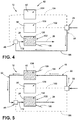
FIG. 4 is a schematic diagram illustrating a freezer-cooling mode of the multi-evaporator refrigeration system; -
FIG. 5 is a schematic flow diagram illustrating a refrigerator-cooling mode of the multi-evaporator refrigeration system; -
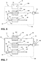
FIG. 6 is a schematic diagram illustrating a pantry-cooling mode of the multi-evaporator refrigeration system; -
FIG. 7 is a schematic diagram illustrating a refrigerator/pantry-cooling mode of the multi-evaporator refrigeration system; -
FIG. 8 is a schematic diagram illustrating an aspect of the multi-evaporator refrigeration system having evaporators disposed proximate the interior mullions of the appliance; and -
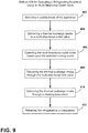
FIG. 9 is a schematic flow diagram illustrating a method for operating the refrigerating appliance utilizing a multi-directional outlet valve. - For purposes of description herein the terms "upper," "lower," "right," "left," "rear," "front," "vertical," "horizontal," and derivatives thereof shall relate to the device as oriented in
FIG. 1 . However, it is to be understood that the device may assume various alternative orientations and step sequences, except where expressly specified to the contrary. It is also to be understood that the specific devices and processes illustrated in the attached drawings, and described in the following specification are simply exemplary embodiments of the inventive concepts defined in the appended claims. Hence, specific dimensions and other physical characteristics relating to the embodiments disclosed herein are not to be considered as limiting, unless the claims expressly state otherwise. - As illustrated in
FIGS. 1-7 , a refrigeratingappliance 10 can include amulti-evaporator refrigeration system 12 that can be operated using asingle compressor 14 and asingle condenser 16 for charging athermal exchange media 18 that can be delivered to one or more of a plurality of evaporators of themulti-evaporator refrigeration system 12. According to various aspects of the device, theappliance 10 can include arefrigerant line 20 having acompressor 14 and acondenser 16. Athermal exchange media 18 is disposed within therefrigerant line 20 and is delivered from thecondenser 16, as acharged media 22, and through therefrigerant line 20 through at least afreezer evaporator 24 of the plurality of evaporators. Thethermal exchange media 18 leaving thefreezer evaporator 24 defines aspent media 26 that is then returned to thecompressor 14. In order to deliver thethermal exchange media 18 to the plurality of evaporators, amulti-directional outlet valve 28 selectively delivers thethermal exchange media 18 to thefreezer evaporator 24. Themulti-directional outlet valve 28 is also adapted to selectively deliver thethermal exchange media 18, in the form of thecharged media 22, to at least onesecondary evaporator 30 of the plurality of evaporators. Thethermal exchange media 18 leaving the one or moresecondary evaporators 30 defines a partially-spent media 32. This partially-spentmedia 32 is then delivered to thefreezer evaporator 24 and ultimately returned back to thecompressor 14 to continue operation of the refrigerant cycle. As discussed above, thethermal exchange media 18 leaving thefreezer evaporator 24 is typically aspent media 26. According to the various aspects of the device, thethermal exchange media 18, regardless of the cooling mode that is being performed by themulti-evaporator refrigeration system 12, is always directed through thefreezer evaporator 24 before returning to thecompressor 14. - Referring again to
FIGS. 1-7 , therefrigerant line 20 can include amulti-directional inlet valve 40 that selectively receives thethermal exchange media 18 for delivery to thefreezer evaporator 24. In this manner, thethermal exchange media 18 can be delivered from themulti-directional outlet valve 28 and directly to themulti-directional inlet valve 40 in the form of thecharged media 22. This cooling mode defines a freezer-cooling mode 42 where all of thecharged media 22 is directed from themulti-directional outlet valve 28, through themulti-directional inlet valve 40 and to thefreezer evaporator 24 for cooling afreezer compartment 44 of theappliance 10. Themulti-directional inlet valve 40, during a pantry-cooling mode 46, refrigerator-cooling mode 48 or combination refrigerator/pantry-cooling mode 50 is adapted to receive the partially-spentmedia 32 from at least one of thesecondary evaporators 30 for delivery to thefreezer evaporator 24 via themulti-directional inlet valve 40. Thesecondary evaporators 30 can include arefrigerator evaporator 52 that is in communication with arefrigerator compartment 54 of theappliance 10. Anothersecondary evaporator 30 can include apantry evaporator 56 that is in communication with apantry compartment 58 of theappliance 10. - Referring again to
FIGS. 2-7 , it is contemplated that each of the freezer, refrigerator andpantry evaporators dedicated expansion device 60 that is included within therefrigerant line 20 and positioned downstream of themulti-directional outlet valve 28. Accordingly, as thethermal exchange media 18 leaves themulti-directional outlet valve 28, thethermal exchange media 18 travels through adedicated expansion device 60 before thethermal exchange media 18 is delivered to a respective evaporator of the freezer, refrigerator andpantry evaporators - During operation of the
multi-evaporator refrigeration system 12, thethermal exchange media 18 is typically delivered to thecompressor 14 from thefreezer evaporator 24. During this compression step, thethermal exchange media 18 leaving thecompressor 14 defines a high-pressure high-temperature vapor 70 that is delivered to thecondenser 16. As thethermal exchange media 18 that is in the form of the high-pressure high-temperature vapor 70 moves through thecondenser 16,heat 100 is rejected from thethermal exchange media 18, and from thecondenser 16. Thethermal exchange media 18 leaving thecondenser 16 is in the form of a high-pressure high-temperature liquid 72 that is moved through therefrigerant line 20. Typically, thethermal exchange media 18 in this state defines thecharged media 22. Thethermal exchange media 18 in this state of a high-pressure high-temperature liquid 72 is then delivered to themulti-directional outlet valve 28. - Referring again to
FIGS. 1-7 , themulti-directional outlet valve 28 is typically operated by aprocessor 80 so that thecharged media 22 is delivered to the appropriate evaporator of the plurality of evaporators for performing a particular cooling mode of theappliance 10. After leaving themulti-directional outlet valve 28, thecharged media 22 in the form of the high-pressure high-temperature liquid 72 is then moved through adedicated expansion device 60 disposed within therefrigerant line 20 leading to a respective evaporator of the plurality of evaporators. After leaving theexpansion device 60, thethermal exchange media 18 is depressurized to define a low-pressure low-temperature liquid 90. In this cooled liquid state, thethermal exchange media 18 is then passed through one of the freezer, pantry andrefrigerator evaporators dedicated expansion device 60. As thethermal exchange media 18 passes through the freezer, pantry andrefrigerator evaporators thermal exchange media 18 changes phase from a liquid to a gas. During this phase change,heat 100 is absorbed by thethermal exchange media 18 and the air around the corresponding evaporator is cooled. - As exemplified in
FIGS. 2 and3 , afan 98 is disposed proximate each evaporator so that as theheat 100 is absorbed within each of the evaporators and the temperature around the respective evaporator is decreased, thefan 98 can be activated to direct this cooled air around the evaporator into a dedicated compartment in theappliance 10. After leaving the evaporator, thethermal exchange media 18 is then in the form of a low-pressure low-temperature vapor 110 that can be delivered back to thecompressor 14 to restart the cycle again. - Typically, the
thermal exchange media 18 leaving one or both of therefrigerator evaporators 52 defines a partially-spent media 32. This partially-spentmedia 32 is then delivered to thefreezer evaporator 24 where additional phase change of the partially-spentmedia 32 may occur. Thethermal exchange media 18 leaving thefreezer evaporator 24 is in the form of thespent media 26. The term "spent media" is used to further define the delivery of thethermal exchange media 18 from thefreezer evaporator 24 and directly to thecompressor 14. Accordingly, thespent media 26 does not typically undergo any additional phase change operations within an evaporator or other heat exchanger as it moves to thecompressor 14 from thefreezer evaporator 24. As such, thespent media 26 may contain part vapor and part liquid forms of thethermal exchange media 18. - Referring again to
FIGS. 1-7 , the selection of the appropriate cooling mode of theappliance 10 can be determined based upon particular settings of a desiredtemperature 120 for each compartment that may be selected, as desired, by the user of theappliance 10.Temperature sensors 122 within each of the freezer, pantry and refrigerator compartments 44, 58, 54 are adapted to monitor anactual temperature 124 therein and deliver this data to aprocessor 80 for theappliance 10. Theprocessor 80 can then compare theactual temperature 124 within the compartment that is measured by thetemperature sensor 122 against the desiredtemperature 120 set by the user. Where theactual temperature 124 is elevated by a predefined amount above the desiredtemperature 120, theappliance 10 can activate themulti-evaporator refrigeration system 12 and operate themulti-directional outlet valve 28 to deliver the chargedmedia 22 to the appropriate evaporator or evaporators of the freezer, refrigerator andpantry evaporators appliance 10. - It is contemplated that a
multi-directional outlet valve 28 can be continually operated to adjust which evaporator the chargedmedia 22 is delivered to, according to the cooling load necessary to have anactual temperature 124 of a particular compartment that matches the desiredtemperature 120 of that same compartment. Accordingly, as themulti-evaporator refrigeration system 12 can run continuously for a period of time, themulti-directional outlet valve 28 can operate to change the cooling mode as needed to createactual temperatures 124 within the various compartments that substantially matches the corresponding desiredtemperature 120 for the various compartments. - Referring again to
FIGS. 1-7 , as discussed previously, each of the freezer, pantry andrefrigerator evaporators multi-evaporator refrigeration system 12 can include adedicated fan 98. In this manner, thepantry evaporator 56 can include apantry fan 130 that is positioned proximate thepantry evaporator 56 for selectively movingpantry process air 132 across thepantry evaporator 56. Accordingly, thepantry fan 130 operates when the chargedmedia 22 is delivered from themulti-directional outlet valve 28 to thepantry evaporator 56. Similarly, therefrigerator evaporator 52 can include arefrigerator fan 134 that is positioned proximate therefrigerator evaporator 52 for selectively movingrefrigerator process air 136 across therefrigerator evaporator 52. Accordingly, therefrigerator fan 134 is adapted to operate to move therefrigerator process air 136 when the chargedmedia 22 is delivered from themulti-directional outlet valve 28 to therefrigerator evaporator 52. In this manner, operation of themulti-directional outlet valve 28 is typically linked to the operation of thepantry fan 130, therefrigerator fan 134 and thefreezer fan 138. - Referring again to
FIGS. 2-7 , because all of thethermal exchange media 18 moving through therefrigerant line 20 ultimately passes through thefreezer evaporator 24 to be returned to thecompressor 14, operation of thefreezer fan 138 may not always be necessary or desired during operation of themulti-evaporator refrigeration system 12. Thefreezer fan 138 is typically positioned proximate thefreezer evaporator 24 for selectively movingfreezer process air 150 across thefreezer evaporator 24. Thefreezer fan 138 operates when thethermal exchange media 18 is delivered from themulti-directional outlet valve 28 and directly to thefreezer evaporator 24 as the chargedmedia 22. - Referring again to
FIGS. 4-7 , when thethermal exchange media 18 is moved through one or both of therefrigerator evaporator 52 andpantry evaporator 56, thefreezer fan 138 may be selectively operable between active andidle states media 32 is delivered from one or both of the pantry orrefrigerator evaporators media 32 to move directly through thefreezer evaporator 24 without operating thefreezer fan 138 in theactive state 152 for movingfreezer process air 150 into thefreezer compartment 44. Such a condition may be used where theactual temperature 124 of thefreezer compartment 44 is substantially similar to the desiredtemperature 120 of thefreezer compartment 44 such that additional cooling is not needed at that particular time. Accordingly, thefreezer fan 138 may define theidle state 154 such that additional cooling or significant amounts of additional cooling are not provided to thefreezer compartment 44. - Alternatively, additional cooling may be necessary within the
freezer compartment 44 as the partially-spentmedia 32 moves through thefreezer evaporator 24. In this condition, thefreezer fan 138 may define theactive state 152. In theactive state 152 of thefreezer fan 138, as the partially-spentmedia 32 is delivered from one of the othersecondary evaporators 30 and through thefreezer evaporator 24, thefreezer fan 138 can operate to provide additional cooling to thefreezer compartment 44 when necessary. - According to various aspects of the device, as the partially-spent
media 32 is moved through thefreezer evaporator 24, additional phase change of the partially-spentmedia 32 may occur as thethermal exchange media 18 moves through thefreezer evaporator 24. Accordingly, the use of thefreezer evaporator 24 in receiving all of thethermal exchange media 18 that moves through therefrigerant line 20 allows for a completion or substantial completion of the phase change of thethermal exchange media 18 to the low-pressure low-temperature vapor 110. By allowing for a complete or substantially complete phase change, thecompressor 14 acting on thethermal exchange media 18 may become more efficient and may also provide greater capacity for thethermal exchange media 18 to rejectheat 100 as it moves through thecondenser 16 and absorbheat 100 as thethermal exchange media 18 moves through one or more of the refrigerator, pantry andfreezer evaporators - Referring again to
FIGS. 2-7 , as discussed previously, themulti-directional outlet valve 28 is operable to define various cooling modes of theappliance 10. At least one of these modes can include amulti-evaporator position 160, such as the refrigerator/pantry-coolingmode 50. In thismulti-evaporator position 160, thethermal exchange media 18, in the form of the chargedmedia 22, can be delivered substantially simultaneously to thepantry evaporator 56 and therefrigerator evaporator 52. As discussed above, after thethermal exchange media 18 leaves the pantry andrefrigerator evaporators media 32, thethermal exchange media 18 is then moved through themulti-directional inlet valve 40 and onto thefreezer evaporator 24. After thethermal exchange media 18 is moved through thefreezer evaporator 24, it is then returned to thecompressor 14 to continue the refrigerant cycle for theappliance 10. - Referring again to
FIGS. 2-7 , themulti-directional inlet valve 40 is positioned downstream of themulti-directional outlet valve 28 and also downstream of the pantry andrefrigerator evaporators multi-directional inlet valve 40 is positioned upstream of thefreezer evaporator 24. In this manner, all of thethermal exchange media 18 leaving themulti-directional outlet valve 28, thepantry evaporator 56 and therefrigerator evaporator 52 can then be directed into and through themulti-directional inlet valve 40. The plurality ofinlets 170 receives thethermal exchange media 18 from various positions within therefrigerant line 20 and allows for combinations of these various paths of thethermal exchange media 18 to be directed to asingle freezer line 172 that delivers thethermal exchange media 18 from themulti-directional inlet valve 40 to thefreezer evaporator 24. Through this configuration, all of thethermal exchange media 18 is directed through thesingle freezer line 172 to be delivered to thefreezer evaporator 24 and then back to thecompressor 14. In this manner, theappliance 10 can be adapted to be free of a separate pump-out operation. Because all of thethermal exchange media 18 is moved through thefreezer evaporator 24, such a pump-out operation may not be necessary. - Additionally, this configuration of the
freezer evaporator 24 connected downstream of themulti-directional inlet valve 40 via thefreezer line 172 directs all of thethermal exchange media 18 through thefreezer evaporator 24 such that a separate check valve is not necessary within themulti-evaporator refrigeration system 12. Accordingly, as thecompressor 14 operates, the high-pressure high-temperature vapor 70 leaving thecompressor 14 is adapted to move through therefrigerant line 20. This movement through therefrigerant line 20 ultimately results in all of thethermal exchange media 18 being moved through themulti-directional inlet valve 40 and then to thefreezer evaporator 24 via thefreezer line 172 and then back to thecompressor 14. The risk of backflow of thethermal exchange media 18 within therefrigerant line 20 is largely eliminated or completely eliminated such that check valve is not necessary. Additionally, the absence of a separate pump-out operation of themulti-evaporator refrigeration system 12 also mitigates or fully eliminates the need for check valves within therefrigerant line 20. - Referring again to
FIGS. 2-7 , the refrigeratingappliance 10 can include therefrigerant line 20 having thecompressor 14 and thethermal exchange media 18 included within therefrigerant line 20. The plurality of heat exchangers are adapted to selectively receive thethermal exchange media 18. As discussed previously, the plurality of heat exchangers includes thefreezer evaporator 24, thepantry evaporator 56 and therefrigerator evaporator 52. Themulti-directional inlet valve 40 is adapted to receive thethermal exchange media 18 from at least one of thecompressor 14, thepantry evaporator 56 and therefrigerator evaporator 52. Accordingly, themulti-directional inlet valve 40 delivers thethermal exchange media 18 to thefreezer evaporator 24. As discussed previously, themulti-directional outlet valve 28 is positioned downstream of thecompressor 14 and upstream of thepantry evaporator 56, arefrigerator evaporator 52 and themulti-directional inlet valve 40. In this manner, as thethermal exchange media 18 is moved through and is apportioned by themulti-directional outlet valve 28, thethermal exchange media 18 passes through various branches of therefrigerant line 20 and is returned to thefreezer evaporator 24 by themulti-directional inlet valve 40. Accordingly, themulti-directional outlet valve 28 receives thethermal exchange media 18 from thecompressor 14 and delivers thethermal exchange media 18 to themulti-directional inlet valve 40. Themulti-directional outlet valve 28 is selectively operable to also deliver thethermal exchange media 18 to at least one of thepantry evaporator 56 and arefrigerator evaporator 52 before being delivered to themulti-directional inlet valve 40. - Referring again to
FIGS. 2-7 , therefrigerant line 20 can include afirst portion 180 that extends from themulti-directional outlet valve 28 and defines a plurality of refrigerant paths that each flow along separate routes to themulti-directional inlet valve 40. These plurality of refrigerant paths can include apantry path 182 that extends through thepantry evaporator 56 and arefrigerator path 184 that extends through therefrigerator evaporator 52. The plurality of refrigerant paths also defines afreezer path 186 that extends directly from themulti-directional outlet valve 28 and to themulti-directional inlet valve 40. Therefrigerant line 20 also includes asecond portion 188 that extends from themulti-directional inlet valve 40 and defines a single return path in the form of thefreezer line 172 that extends through thefreezer evaporator 24 and then returns to thecompressor 14. Because of the single return path, the pump-out operation and check valves are typically not needed in therefrigerant line 20. - Referring now to
FIGS. 4-7 , the various cooling modes of theappliance 10 are illustrated for exemplifying at least a portion of the cooling modes of the multi-evaporator refrigerant system. As exemplified inFIG. 4 , thethermal exchange media 18 is moved through themulti-directional outlet valve 28 and is directly moved to themulti-directional inlet valve 40. Thethermal exchange media 18 is then moved directly into thefreezer evaporator 24 for cooling afreezer compartment 44. In this freezer-coolingmode 42, little, if any, of thethermal exchange media 18 is delivered to the pantry or therefrigerator evaporators - As exemplified in
FIG. 5 , a refrigerator-coolingmode 48 is shown where thethermal exchange media 18 is moved from themulti-directional outlet valve 28 and through therefrigerator evaporator 52. In this refrigerator-coolingmode 48, therefrigerator fan 134 is activated in conjunction with the operation of themulti-directional outlet valve 28 so that asheat 100 is absorbed within therefrigerator evaporator 52, cooledrefrigerator process air 136 is formed around therefrigerator evaporator 52 and therefrigerator fan 134 can move thisrefrigerator process air 136 into therefrigerator compartment 54 for cooling therefrigerator compartment 54. After leaving therefrigerator evaporator 52, thethermal exchange media 18 defines the partially-spentmedia 32 that is then returned to themulti-directional inlet valve 40. This partially-spentmedia 32 is then directed to thefreezer evaporator 24. In the refrigerator-coolingmode 48, thefreezer fan 138 can selectively define theactive state 152 or theidle state 154, based upon whether additional cooling is needed within thefreezer compartment 44. As the partially-spentmedia 32 is moved through thefreezer evaporator 24, additional phase change occurs to thethermal exchange media 18 as it moves through thefreezer evaporator 24. This phase change defines cooledfreezer process air 150 that forms around afreezer evaporator 24, thefreezer fan 138 can selectively operate to move thisfreezer process air 150 into thefreezer compartment 44. In various aspects of the device, when no cooling is needed in thefreezer compartment 44, thefreezer fan 138 can also be multi-directional such that thefreezer process air 150 can be moved to other portions of theappliance 10 such as to thepantry compartment 58 or therefrigerator compartment 54. - Referring now to
FIG. 6 , which exemplifies a pantry-coolingmode 46 of theappliance 10, thethermal exchange media 18 is moved through themulti-directional outlet valve 28 and to thepantry evaporator 56. As thethermal exchange media 18 moves through thepantry evaporator 56, thethermal exchange media 18 undergoes the phase change and absorbsheat 100, thereby forming cooledpantry process air 132 around thepantry evaporator 56. Thepantry fan 130 operates in conjunction with themulti-directional outlet valve 28 moved in the pantry-coolingmode 46 and moves thepantry process air 132 into thepantry compartment 58. As with the refrigerator-coolingmode 48, thethermal exchange media 18 leaving thepantry evaporator 56 defines the partially-spentmedia 32 that is then moved to themulti-directional inlet valve 40 and then to thefreezer evaporator 24. Again, thefreezer fan 138 may define theactive state 152 or theidle state 154 depending upon whether cooling is needed within thefreezer compartment 44. Where amulti-directional freezer fan 138 is implemented, the freezer process may also be moved to another portion of theappliance 10 other than, or in addition to, thefreezer compartment 44. - Referring now to
FIG. 7 , a combination refrigerator/pantry-coolingmode 50 is defined wherethermal exchange media 18 leaving themulti-directional outlet valve 28 is moved to both the refrigerator andpantry evaporators thermal exchange media 18 absorbsheat 100 from around each of the refrigerator andpantry evaporators refrigerator process air 136 andpantry process air 132, respectively. The refrigerator andpantry fans refrigerator process air 136 andpantry process air 132 into the refrigerator andpantry compartments Thermal exchange media 18 leaving the refrigerator andpantry evaporators media 32 that is then delivered through themulti-directional inlet valve 40 to thefreezer evaporator 24. Again, thefreezer fan 138 may define theactive state 152 or theidle state 154 depending upon whether additional cooling is needed within thefreezer evaporator 24. - According to various aspects of the device, the
multi-directional outlet valve 28 can be operated byvarious valve actuators 196. Thesevalve actuators 196 can include an electric actuator, hydraulic actuators, pneumatic actuators, spring-loaded actuators, and othersimilar valve actuators 196. Where an electrical actuator is used, the electrical actuator can be in the form of a stepper motor, servo motor, electro valve, or other similar actuators. In various aspects of the device, themulti-directional inlet valve 40 may also include avalve actuator 196 that operates themulti-directional inlet valve 40 cooperatively with themulti-directional outlet valve 28. - Referring now to
FIG. 8 , another aspect of themulti-evaporator refrigeration system 12 is disclosed. In this aspect of the device, one or more of a plurality of evaporators can be disposed within amullion 210 orfalse mullion 212 of theappliance 10 and proximate two adjacent compartments within theappliance 10. Accordingly, as exemplified inFIG. 8 , thefreezer evaporator 24 can be positioned adjacent thefreezer compartment 44 and thepantry compartment 58 and thepantry evaporator 56 can be disposed adjacent thepantry compartment 58 and therefrigerator compartment 54. In this manner, therefrigerator fan 134,pantry fan 130, andfreezer fan 138 can be operated to provide cooling functionality to multiple compartments. In such an embodiment, additional cooling can be provided to a single compartment and from multiple evaporators, where greater amounts of cooling are needed in a short period of time. - Referring now to
FIGS. 1-9 , having described various aspects of the device, a method 400 is disclosed for operating a refrigeratingappliance 10, using amulti-directional outlet valve 28 for delivering athermal exchange media 18 to one or more evaporators. According to the method 400, a refrigerating mode of theappliance 10 is selected (step 402). Selecting the appropriate refrigerating mode can be accomplished manually through auser interface 220 or automatically through use of aprocessor 80 in communication withvarious temperature sensors 122 disposed within therefrigerator compartment 54, thepantry compartment 58 and thefreezer compartment 44. Thesetemperature sensors 122 monitor theactual temperature 124 within each respective compartment and deliver this information to aprocessor 80. Theprocessor 80 then monitors the currentactual temperature 124 within each of the compartments and compares theseactual temperatures 124 with a corresponding desiredtemperature 120 set by the user. Where theactual temperature 124 is above the desiredtemperature 120, a particular refrigerating mode can be actuated in order to provide cooling to an appropriate compartment. After the refrigerating mode is selected, thethermal exchange media 18, typically in the form of a refrigerant, can be delivered to the multi-directional outlet valve 28 (step 404). As discussed above, thethermal exchange media 18 moves from thecompressor 14 through thecondenser 16 and then to themulti-directional outlet valve 28. It is contemplated that various dryers and other fixtures typically seen within refrigerating systems can be disposed within therefrigerant line 20 between thecondenser 16 and themulti-directional outlet valve 28. - After the refrigerating mode is selected and the
thermal exchange media 18 is delivered to themulti-directional outlet valve 28, themulti-directional outlet valve 28 is operated based upon the selected mode of the appliance 10 (step 406). In this manner, themulti-directional outlet valve 28 is operated so that the appropriate evaporator or evaporators are placed in communication with thecompressor 14 andcondenser 16 via themulti-directional outlet valve 28. Thethermal exchange media 18 is then delivered through the multi-directional inlet valve 40 (step 408). As discussed previously in all refrigerating modes of theappliance 10, thethermal exchange media 18 is moved from themulti-directional outlet valve 28 and then to themulti-directional inlet valve 40. Depending upon the refrigerating mode, thethermal exchange media 18 may also be delivered through one or both of thepantry evaporator 56 and therefrigerator evaporator 52 and then moved onto themulti-directional inlet valve 40. After moving through themulti-directional inlet valve 40, thethermal exchange media 18 is then moved through the freezer evaporator 24 (step 410). When the freezer-coolingmode 42 is selected, thethermal exchange media 18 moves directly from themulti-directional outlet valve 28 to themulti-directional inlet valve 40 and then to thefreezer evaporator 24. Where the selected cooling mode is one of the pantry-coolingmode 46, refrigerator-coolingmode 48 or a combination refrigerator/pantry-coolingmode 50, thethermal exchange media 18 is in the form of a partially-spentmedia 32 that is then delivered to themulti-directional inlet valve 40. This partially-spentmedia 32 is then moved to thefreezer evaporator 24. As the partially-spentmedia 32 moves through thefreezer evaporator 24, additional phase change of thethermal exchange media 18 may occur whereadditional heat 100 is absorbed by thethermal exchange media 18 moving through thefreezer evaporator 24. After moving through thefreezer evaporator 24, thethermal exchange media 18 is then returned to the compressor 14 (step 412). - According to various aspects of the device, the
multi-evaporator refrigeration system 12 can be used withinvarious appliances 10 that have separate areas that are to be cooled by a single refrigerating system.Such appliances 10 can include, but are not limited to, freezers, refrigerators, coolers, combinations thereof and othersimilar appliances 10. - According to various aspects of the device, the
thermal exchange media 18 can be in the form of a refrigerant, water, air, and other similar media that can be used to absorb and rejectheat 100 for cooling various portions of a refrigeratingappliance 10. - According to various aspects of the device, the
multi-directional outlet valve 28 can include a single input port and multiple output ports. As exemplified inFIGS. 2-8 , themulti-directional outlet valve 28 includes three output ports. It is contemplated that themulti-directional outlet valve 28 can include more output ports for serving various portions of anappliance 10. These portions can include, but are not limited to, ice makers, chillers, additional pantry spaces within apantry compartment 58, crispers and other similar compartments within theappliance 10.
Claims (15)
- A refrigeration system (12) comprising:a refrigerant line (20) having a compressor (14) and a condenser (16);a thermal exchange media (18) that is delivered from the condenser (16) and through the refrigerant line (20) to at least a freezer evaporator (24) of a plurality of evaporators, wherein the thermal exchange media (18) leaving the freezer evaporator (24) defines spent media (26) that is returned to the compressor (14); anda multi-directional outlet valve (28) that selectively delivers the thermal exchange media (18) to the freezer evaporator (24), wherein the multi-directional outlet valve (28) also selectively delivers the thermal exchange media (18) to at least one secondary evaporator (30) of the plurality of evaporators to define a partially-spent media (32) that is delivered to the freezer evaporator (24).
- The refrigeration system (12) of claim 1, wherein the refrigerant line (20) includes a multi-directional inlet valve (40) that selectively receives at least one of the thermal exchange media (18) from the multi-directional outlet valve (28) and the partially-spent media (32) from the at least one secondary evaporator (30) for delivery to the freezer evaporator (24).
- The refrigeration system (12) of any one or more of claims 1-2, wherein the freezer evaporator (24) and each of the at least one secondary evaporators (30) includes a dedicated expansion device (60) that is positioned within the refrigerant line (20) and downstream of the multi-directional outlet valve (28).
- The refrigeration system (12) of any one or more of claims 1-3, wherein the at least one secondary evaporator (30) includes a pantry evaporator (56) and a refrigerator evaporator (52).
- The refrigeration system (12) of claim 4, wherein a pantry fan (130) is positioned proximate the pantry evaporator (56) for selectively moving pantry process air (132) across the pantry evaporator (56), wherein the pantry fan (130) operates when the thermal exchange media (18) is delivered from the multi-directional outlet valve (28) to the pantry evaporator (56).
- The refrigeration system (12) of any one or more of claims 4-5, wherein a refrigerator fan (134) is positioned proximate the refrigerator evaporator (52) for selectively moving refrigerator process air (136) across the refrigerator evaporator (52).
- The refrigeration system (12) of claim 6, wherein the refrigerator fan (134) operates when the thermal exchange media (18) is delivered from the multi-directional outlet valve (28) to the refrigerator evaporator (52).
- The refrigeration system (12) of any one or more of claims 4-7, wherein a freezer fan (138) is positioned proximate the freezer evaporator (24) for selectively moving freezer process air (150) across the freezer evaporator (24), wherein the freezer fan (138) operates when the thermal exchange media (18) is delivered from the multi-directional outlet valve (28) to the freezer evaporator (24).
- The refrigeration system (12) of claim 8, wherein the freezer fan (138) is selectively operable between active and idle states (152, 154) when the partially-spent media (32) is delivered from at least one of the pantry and refrigerator evaporators (56, 52) to the freezer evaporator (24).
- The refrigeration system (12) of claim 9, wherein the idle state (154) of the freezer fan (138) defines passage of the partially-spent media (32) through the freezer evaporator (24) when a freezer compartment (44) served by the freezer evaporator (24) defines a desired freezer temperature.
- The refrigeration system (12) of any one or more of claims 9-10, wherein the multi-directional outlet valve (28) is operable to define a multi-evaporator position (160), wherein the thermal exchange media (18) is delivered substantially simultaneously to the pantry evaporator (56) and the refrigerator evaporator (52).
- The refrigeration system (12) of any one or more of claim 1-11, wherein the refrigerant line (20) is free of check valves.
- The refrigeration system (12) of any one or more of claims 1-12, wherein the refrigerant line (20) is free of a separate pump-out operation.
- A refrigerating appliance (10) that includes the refrigeration system (12) of any one or more of claims 4-13, the refrigerating appliance (10) comprising:a freezer compartment (44) that corresponds to the freezer evaporator (24);a refrigerator compartment (54) that corresponds to the refrigerator evaporator (52); anda pantry compartment (58) that corresponds to the pantry evaporator (56).
- A method (400) for operating the refrigerating appliance (10) of claim 14, the method (400) comprising steps of:selecting a refrigerating mode of the refrigerating appliance (10);delivering the thermal exchange media (18) to the multi-directional outlet valve (28);operating the multi-directional outlet valve (28) based upon a selected mode of the refrigerating appliance (10);delivering the thermal exchange media (18) through the multi-directional inlet valve (40);delivering the thermal exchange media (18) through the freezer evaporator (24); andreturning the thermal exchange media (18) to the compressor (14), wherein the refrigerating modes include a pantry-cooling mode (46), a refrigerator-cooling mode (48), a freezer-cooling mode (42) and a pantry/refrigerator-cooling mode (50), and wherein each of the modes delivers the thermal exchange media (18) through the multi-directional outlet valve (28), the multi-directional inlet valve (40) and the freezer evaporator (24), sequentially.
Applications Claiming Priority (1)
| Application Number | Priority Date | Filing Date | Title |
|---|---|---|---|
| US15/611,294 US10514194B2 (en) | 2017-06-01 | 2017-06-01 | Multi-evaporator appliance having a multi-directional valve for delivering refrigerant to the evaporators |
Publications (1)
| Publication Number | Publication Date |
|---|---|
| EP3410036A1 true EP3410036A1 (en) | 2018-12-05 |
Family
ID=62165370
Family Applications (1)
| Application Number | Title | Priority Date | Filing Date |
|---|---|---|---|
| EP18171959.2A Withdrawn EP3410036A1 (en) | 2017-06-01 | 2018-05-11 | Multi-evaporator appliance having a multi-directional valve for delivering refrigerant to the evaporators |
Country Status (2)
| Country | Link |
|---|---|
| US (2) | US10514194B2 (en) |
| EP (1) | EP3410036A1 (en) |
Families Citing this family (3)
| Publication number | Priority date | Publication date | Assignee | Title |
|---|---|---|---|---|
| US10712073B2 (en) * | 2017-03-01 | 2020-07-14 | Haier Us Appliance Solutions, Inc. | Ternary natural refrigerant mixture that improves the energy efficiency of a refrigeration system |
| US11698223B2 (en) | 2020-01-21 | 2023-07-11 | Whirlpool Corporation | System and method for temperature control of refrigerator with convertible compartment |
| US11649999B2 (en) | 2021-05-14 | 2023-05-16 | Electrolux Home Products, Inc. | Direct cooling ice maker with cooling system |
Citations (3)
| Publication number | Priority date | Publication date | Assignee | Title |
|---|---|---|---|---|
| WO2003016793A1 (en) * | 2001-08-16 | 2003-02-27 | BSH Bosch und Siemens Hausgeräte GmbH | Combined refrigerating appliance and evaporating system therefor |
| EP2631578A2 (en) * | 2012-02-21 | 2013-08-28 | Whirlpool Corporation | Refrigerator with variable capacity compressor and cycle priming action through capacity control and associated methods |
| WO2016063179A1 (en) * | 2014-10-23 | 2016-04-28 | Indesit Company S.P.A. | Refrigerating appliance with a variable-temperature compartment |
Family Cites Families (256)
| Publication number | Priority date | Publication date | Assignee | Title |
|---|---|---|---|---|
| US2515825A (en) | 1945-03-16 | 1950-07-18 | Carrier Corp | Single stage refrigeration utilizing holdover means |
| US2873041A (en) | 1956-12-03 | 1959-02-10 | Carrier Corp | Breaker strip construction |
| US2934023A (en) | 1956-12-31 | 1960-04-26 | Murray Corp | Centrifugal pumps |
| US3342961A (en) | 1960-09-19 | 1967-09-19 | Gen Motors Corp | Thermostat having thermally responsive means for arresting the movement of one of the contacts upon cooling of the thermostat |
| US3196553A (en) | 1960-09-19 | 1965-07-27 | Gen Motors Corp | Temperature responsive timer control for a clothes drier |
| US3218730A (en) | 1962-06-14 | 1965-11-23 | Gen Motors Corp | Termination control for a condensing clothes dryer |
| US3653807A (en) | 1970-08-24 | 1972-04-04 | Whirlpool Co | Method and means for shredding and filtering lint in a washing machine |
| US3805404A (en) | 1973-07-02 | 1974-04-23 | I Gould | Water cooled condenser dryer for laundry center |
| US3953146A (en) | 1974-08-15 | 1976-04-27 | Whirlpool Corporation | Apparatus for treating lint in an automatic washer |
| US3999304A (en) | 1975-07-18 | 1976-12-28 | Doty Edward E | Clothes dryer filter and exhaust system |
| US4137647A (en) | 1977-09-06 | 1979-02-06 | Clark Jr James N | Heat and humidity recovery device for use with clothes dryer |
| US4134518A (en) | 1978-01-23 | 1979-01-16 | Bernie Menchen | Cold box with breaker strip |
| NL7801958A (en) | 1978-02-21 | 1979-08-23 | Zephyr Koel En Luchttechniek B | Refrigerated transport container system - has secondary circuit with pump and containing liq. refrigerating agent |
| US4261179A (en) | 1978-09-22 | 1981-04-14 | Ardco, Inc. | Input control system |
| US4260876A (en) | 1978-12-11 | 1981-04-07 | Anthony's Manufacturing Company, Inc. | Dew point differential power controller |
| GB2087029A (en) | 1980-09-19 | 1982-05-19 | Heat Pumps W R Ltd | Improvements in or Relating to Heat Exchangers |
| DE3147796A1 (en) | 1981-08-18 | 1983-03-03 | Spraytech AB, 18400 Åkersberga | Device for cleaning the warm exhaust air of a linen drier |
| US4860921A (en) | 1984-05-09 | 1989-08-29 | Edward Gidseg | Thermal breaker strip for refrigeration cabinets |
| US4603489A (en) | 1984-10-05 | 1986-08-05 | Michael Goldberg | Heat pump closed loop drying |
| US4870735A (en) | 1987-07-31 | 1989-10-03 | White Consolidated Industries, Inc. | Refrigeration cabinet construction |
| DE3738031C2 (en) | 1987-11-09 | 1995-10-12 | Bosch Siemens Hausgeraete | Method and device for removing lint from a condensate separator designed as a heat exchanger |
| IT1243685B (en) | 1990-07-24 | 1994-06-21 | Eurodomestici Ind Riunite | DEVICE FOR THE CLEANING OF AN EVAPORATOR, PROVIDED FOR IN A MACHINE-DRYER OR SIMILAR, FROM ELEMENTS RELEASED BY CLOTHING OR SIMILAR PRESENT IN THE BASKET OF SUCH MACHINE |
| KR950001350B1 (en) | 1992-02-25 | 1995-02-17 | 동양매직 주식회사 | Washing machine |
| DE4304372A1 (en) | 1993-02-13 | 1994-08-18 | Miele & Cie | Drying appliance, especially condensation-type laundry dryer, with a heat pump |
| KR0140503B1 (en) * | 1993-02-25 | 1997-06-10 | 김광호 | Refrigerator that can change function of compartment and its control method |
| DE4409607C2 (en) | 1993-04-21 | 2002-03-14 | Miele & Cie | Condensation clothes dryer with a heat pump |
| US5628122A (en) | 1994-10-05 | 1997-05-13 | Peter And Theordore Spinardi Investments | Lint remover for a clothes drying machine |
| US5720536A (en) | 1995-03-27 | 1998-02-24 | General Electric Company | Refrigerator with improved breaker strip assembly |
| US5600966A (en) | 1995-05-19 | 1997-02-11 | Forma Scientific, Inc. | Ultra low temperature split door freezer |
| IT1284443B1 (en) | 1996-06-26 | 1998-05-21 | Candy Spa | DOMESTIC WASHING MACHINE WITH CLOSED DRYING CIRCUIT, AIR CONDENSATION OF THE STEAM AND SELF-CLEANING FILTER |
| US5666817A (en) | 1996-12-10 | 1997-09-16 | Edward R. Schulak | Energy transfer system for refrigerator/freezer components |
| US5927095A (en) | 1997-05-20 | 1999-07-27 | Lg Electronics, Inc. | Anti-frost device for refrigerators |
| JP4018238B2 (en) | 1997-05-27 | 2007-12-05 | エルジー エレクトロニクス インコーポレイティド | Cold air supply system for refrigerator |
| DE69832212T2 (en) | 1997-05-28 | 2006-07-20 | Lg Electronics Inc. | fridge |
| KR100223225B1 (en) | 1997-08-28 | 1999-10-15 | 구자홍 | Refrigerator room temperature control method and apparatus |
| KR100254409B1 (en) | 1997-08-29 | 2000-05-01 | 구자홍 | Circulator for cooling air |
| KR100288261B1 (en) | 1998-06-30 | 2001-05-02 | 전주범 | Dew device of refrigerator |
| EP0999302B1 (en) | 1998-10-21 | 2003-08-20 | Whirlpool Corporation | Tumble dryer with a heat pump |
| ATE247735T1 (en) | 1999-04-30 | 2003-09-15 | Bsh Bosch Siemens Hausgeraete | METHOD FOR CLEANING THE PROCESS AIR LINE OF A DOMESTIC LAUNDRY DRYER AND A HOUSEHOLD LAUNDRY DRYER SET UP TO PERFORM THIS METHOD |
| DE10002743B4 (en) | 2000-01-22 | 2006-01-12 | Whirlpool Corp., Benton Harbor | Heat pump tumble dryer with cleaning device for the heat exchanger |
| DE10002742C1 (en) | 2000-01-22 | 2001-06-28 | Whirlpool Co | Heat pump washer-dryer has channel wall forming or carrying removable condensate collection unit, adjustable cleaning device near heat exchanger inlet removing adhering fluff |
| DE20001253U1 (en) | 2000-01-25 | 2001-06-07 | Liebherr-Hausgeräte GmbH, 88416 Ochsenhausen | Refrigerator with a refrigerator, a cold storage and a freezer compartment |
| CA2355155C (en) | 2000-08-16 | 2009-10-13 | Lg Electronics Inc. | Door cooling apparatus for refrigerator with double-acting door |
| JP4028688B2 (en) | 2001-03-21 | 2007-12-26 | 株式会社東芝 | refrigerator |
| DE10116238B4 (en) | 2001-03-31 | 2005-03-10 | Whirlpool Co | Clothes dryer with heat pump |
| US6983615B2 (en) | 2001-07-16 | 2006-01-10 | Maytag Corporation | French door chiller compartment for refrigerators |
| DE10143242A1 (en) | 2001-09-04 | 2003-03-20 | Bsh Bosch Siemens Hausgeraete | Refrigeration device with cooling air circulation |
| NZ534444A (en) | 2002-02-22 | 2006-02-24 | Multibras S | |
| JP2004053055A (en) | 2002-07-17 | 2004-02-19 | Sanyo Electric Co Ltd | Refrigerator |
| US6973799B2 (en) | 2002-08-27 | 2005-12-13 | Whirlpool Corporation | Distributed refrigeration system for a vehicle |
| KR100487329B1 (en) | 2002-10-10 | 2005-05-03 | 엘지전자 주식회사 | Condensing Type Clothes Drier and Controlling the Same |
| JP3696224B2 (en) | 2003-03-19 | 2005-09-14 | 株式会社グリーンセイジュ | Drying system |
| BR0301406A (en) | 2003-04-15 | 2004-12-07 | Multibras Eletrodomesticos Sa | Arrangement for forced air circulation in refrigerators and freezers |
| US7168274B2 (en) | 2003-05-05 | 2007-01-30 | American Dryer Corporation | Combination washer/dryer having common heat source |
| NZ526361A (en) | 2003-05-30 | 2006-02-24 | Fisher & Paykel Appliances Ltd | Compressor improvements |
| US6793010B1 (en) | 2003-06-06 | 2004-09-21 | Tecumseh Products Company | Heat exchanger having non-perpendicularly aligned heat transfer elements |
| JP2005027768A (en) | 2003-07-09 | 2005-02-03 | Mitsubishi Electric Corp | Clothes dryer |
| CA2438766C (en) | 2003-08-29 | 2008-12-30 | Maytag Corporation | Refrigerator incorporating french doors with rotating mullion bar |
| KR100565622B1 (en) | 2003-09-19 | 2006-03-30 | 엘지전자 주식회사 | Refrigerator |
| US20070051127A1 (en) | 2003-09-26 | 2007-03-08 | Ssw Holding Company, Inc. | Cooling tubes for shelving |
| RU2006114770A (en) | 2003-09-29 | 2007-11-10 | Селф Пропеллед Рисерч энд Дивелопмент Спешелистс,эЛэЛСи (US) | DRYING DEVICE (OPTIONS), WASHING DEVICE AND DRYING CHAMBER (OPTIONS) |
| EP1548380A3 (en) | 2003-12-22 | 2006-10-04 | Hussmann Corporation | Flat-tube evaporator with micro-distributor |
| EP1564325B1 (en) | 2004-02-10 | 2018-04-11 | Electrolux Home Products Corporation N.V. | Improved clothes drying machine with clothes smoothing ability |
| US20050229614A1 (en) | 2004-04-02 | 2005-10-20 | Altech Controls, Inc. | Anti-sweat heater control system and method |
| KR100531834B1 (en) | 2004-04-06 | 2005-11-30 | 엘지전자 주식회사 | Exhaustion type clothes dryer with air inlet guide |
| US7281387B2 (en) | 2004-04-29 | 2007-10-16 | Carrier Commercial Refrigeration Inc. | Foul-resistant condenser using microchannel tubing |
| JP2006017338A (en) | 2004-06-30 | 2006-01-19 | Toshiba Corp | refrigerator |
| US7421846B2 (en) | 2004-08-18 | 2008-09-09 | Ice Energy, Inc. | Thermal energy storage and cooling system with gravity fed secondary refrigerant isolation |
| KR100738714B1 (en) | 2004-12-10 | 2007-07-12 | 엘지전자 주식회사 | Drying Washer |
| JP2006187449A (en) | 2005-01-06 | 2006-07-20 | Toshiba Corp | Washing and drying machine |
| US7775065B2 (en) | 2005-01-14 | 2010-08-17 | General Electric Company | Methods and apparatus for operating a refrigerator |
| US20080307823A1 (en) | 2005-02-01 | 2008-12-18 | Lg Electronics Inc. | Refrigerator |
| US7207181B2 (en) | 2005-03-01 | 2007-04-24 | Bradley W. Geuke | Refrigeration unit condensation prevention |
| JP4834342B2 (en) | 2005-07-26 | 2011-12-14 | 株式会社東芝 | Drum type washer / dryer |
| KR100925908B1 (en) | 2005-07-28 | 2009-11-09 | 샤프 가부시키가이샤 | Drum type drying and washing machine |
| DE102005035652A1 (en) | 2005-07-29 | 2007-02-01 | BSH Bosch und Siemens Hausgeräte GmbH | Heat exchanger device for a tumble dryer |
| KR100661663B1 (en) | 2005-08-12 | 2006-12-26 | 삼성전자주식회사 | Refrigerator and its control method |
| KR101137335B1 (en) | 2005-08-25 | 2012-04-19 | 엘지전자 주식회사 | operating method for laundry machine |
| DE102005041145A1 (en) | 2005-08-29 | 2007-03-01 | Alpha-Innotec Gmbh | Laundry dryer, has heat pump heating system comprising compressor with changeable output, and controller controlling and/or regulating output of compressor based on residual moisture in laundry that is to be dried |
| US9663894B2 (en) | 2005-11-10 | 2017-05-30 | Lg Electronics Inc. | Steam generator and laundry dryer having the same and controlling method thereof |
| JP4661590B2 (en) | 2005-12-27 | 2011-03-30 | パナソニック株式会社 | Motor drive device for washing and drying machine |
| DE102005062940A1 (en) | 2005-12-29 | 2007-07-05 | BSH Bosch und Siemens Hausgeräte GmbH | A method for drying washing has a heat pump by which circulated air through the washing chamber is dried and heated and an additional heat pump evaporator is arranged to predry the circulated air stream |
| DE102006007420A1 (en) | 2006-02-17 | 2007-08-30 | BSH Bosch und Siemens Hausgeräte GmbH | Cleaning device for a component within a process air cycle of a household laundry drier |
| DE102006007443A1 (en) | 2006-02-17 | 2007-08-23 | BSH Bosch und Siemens Hausgeräte GmbH | Cleaning device for a component of a household laundry drier |
| DE102006018469A1 (en) | 2006-04-19 | 2007-10-25 | Lare Luft- und Kältetechnik Apparate und Regelsysteme GmbH | Cloth drier comprises a replaceable or cleanable water filter, electric control with a program for controlling a pump and a component for opening and closing a flow pipeline, heat pump system, aerator, condenser, compressor and evaporator |
| EP1852539B1 (en) | 2006-05-02 | 2010-07-14 | Electrolux Home Products Corporation N.V. | Drying program with anti-crease phase and dryer |
| KR100783211B1 (en) | 2006-07-19 | 2007-12-06 | 엘지전자 주식회사 | Valve assembly for preventing leakage of refrigerant in refrigerator |
| KR100808180B1 (en) * | 2006-11-09 | 2008-02-29 | 엘지전자 주식회사 | Refrigeration cycle unit and refrigerator |
| US7610773B2 (en) | 2006-12-14 | 2009-11-03 | General Electric Company | Ice producing apparatus and method |
| DE102006061211A1 (en) | 2006-12-22 | 2008-06-26 | BSH Bosch und Siemens Hausgeräte GmbH | Method for removing lint from a heat exchanger of a domestic appliance, and corresponding domestic appliance |
| DE102006061737B3 (en) | 2006-12-28 | 2008-04-24 | BSH Bosch und Siemens Hausgeräte GmbH | Condensing dryer has fan driven circuit for processing air and a heat pump circuit with a secondary fluid circuit between them |
| DE102007002181B3 (en) | 2007-01-15 | 2008-08-21 | BSH Bosch und Siemens Hausgeräte GmbH | Condensation dryer with a heat pump |
| KR100820151B1 (en) | 2007-02-20 | 2008-04-08 | 엘지전자 주식회사 | Ductless dryer |
| DE102007012071A1 (en) | 2007-03-13 | 2008-09-18 | BSH Bosch und Siemens Hausgeräte GmbH | Washer dryer with improved lint removal and process for its operation |
| DE102007016074A1 (en) | 2007-04-03 | 2008-10-09 | BSH Bosch und Siemens Hausgeräte GmbH | Method and device for cleaning a component, in particular an evaporator of a condenser device, and laundry or tumble dryer with such a device |
| CN101324389B (en) | 2007-06-13 | 2011-11-09 | 博西华家用电器有限公司 | Condenser combination and household electrical appliance using the same |
| EP2203585B1 (en) | 2007-09-04 | 2017-08-16 | LG Electronics Inc. | Dehumidifying apparatus for dryer |
| DE102007052835A1 (en) | 2007-11-06 | 2009-05-07 | BSH Bosch und Siemens Hausgeräte GmbH | Method and device for cleaning a component, in particular an evaporator of a condenser device, and laundry or tumble dryer with such a device |
| DE102007060854A1 (en) | 2007-12-18 | 2009-06-25 | BSH Bosch und Siemens Hausgeräte GmbH | Cleaning device for a component loaded with lint in a domestic appliance, and domestic appliance and method for cleaning a component loaded with lint |
| EP2225528B1 (en) | 2007-12-18 | 2011-09-07 | A-Heat AlliedHeat Exchange Technology AG | Heat exchange system |
| DE102007060851A1 (en) | 2007-12-18 | 2009-06-25 | BSH Bosch und Siemens Hausgeräte GmbH | Household appliance for the care of laundry items and method for removing lint |
| JP2011506903A (en) | 2007-12-18 | 2011-03-03 | アー − ヒート アライド ヒート イクスチェンジ テクノロジー アクチェンゲゼルシャフト | Heat exchanger |
| US8806886B2 (en) | 2007-12-20 | 2014-08-19 | General Electric Company | Temperature controlled devices |
| US8099975B2 (en) | 2007-12-31 | 2012-01-24 | General Electric Company | Icemaker for a refrigerator |
| WO2009089460A2 (en) | 2008-01-09 | 2009-07-16 | International Mezzo Technologies, Inc. | Corrugated micro tube heat exchanger |
| DE102008007971A1 (en) | 2008-02-07 | 2009-08-13 | BSH Bosch und Siemens Hausgeräte GmbH | Condensation dryer with heat pump and heater and method for its operation |
| CA2629470A1 (en) | 2008-04-18 | 2009-10-18 | Mabe Canada Inc. | Clothes dryer with thermal insulation pad |
| US8794026B2 (en) | 2008-04-18 | 2014-08-05 | Whirlpool Corporation | Secondary cooling apparatus and method for a refrigerator |
| DE102008020351A1 (en) | 2008-04-23 | 2009-10-29 | Valeo Klimasysteme Gmbh | Method for operating an air conditioning system for a motor vehicle |
| DE102008020556A1 (en) | 2008-04-24 | 2009-10-29 | BSH Bosch und Siemens Hausgeräte GmbH | Exhaust air dryer with reduced condensate formation and method for its operation |
| PL2138627T3 (en) | 2008-06-27 | 2017-01-31 | BSH Hausgeräte GmbH | Dryer comprising a heat sink and a condensate container |
| DE102008032800A1 (en) | 2008-07-11 | 2010-01-14 | BSH Bosch und Siemens Hausgeräte GmbH | Device for cleaning a component, in particular an evaporator of a capacitor device |
| DE102008033388B4 (en) | 2008-07-16 | 2020-07-16 | BSH Hausgeräte GmbH | Dryer with heat pump circuit |
| US8104191B2 (en) | 2008-07-31 | 2012-01-31 | Electrolux Home Products, Inc. | Laundry dryer providing moisture application during tumbling and reduced airflow |
| DE102008040946A1 (en) | 2008-08-01 | 2010-02-04 | BSH Bosch und Siemens Hausgeräte GmbH | Condensation dryer with a heat pump and detection of an impermissible operating state and method for its operation |
| DE102008041998A1 (en) | 2008-09-11 | 2010-03-18 | BSH Bosch und Siemens Hausgeräte GmbH | Dryer with a lint filter and a cleaning device |
| KR101549861B1 (en) | 2008-09-16 | 2015-09-03 | 엘지전자 주식회사 | ductless dryer |
| AU2009301278B2 (en) | 2008-10-08 | 2015-11-19 | A-Heat Allied Heat Exchange Technology Ag | Heat exchanger assembly and method for the operation thereof |
| DE102008043920A1 (en) | 2008-11-20 | 2010-05-27 | BSH Bosch und Siemens Hausgeräte GmbH | Condensation dryer with a heat pump and method for its operation |
| EP2189568B1 (en) | 2008-11-21 | 2012-01-04 | Electrolux Home Products Corporation N.V. | Laundry washing and drying machine |
| DE102008044323A1 (en) | 2008-12-03 | 2010-06-10 | BSH Bosch und Siemens Hausgeräte GmbH | Condensation dryer with a housing |
| DE102008054548A1 (en) | 2008-12-11 | 2010-06-17 | BSH Bosch und Siemens Hausgeräte GmbH | Dryer with recirculating air and process for its operation |
| DE102008054693A1 (en) | 2008-12-16 | 2010-06-17 | BSH Bosch und Siemens Hausgeräte GmbH | Condensation dryer and method for its operation |
| DE102008054832A1 (en) | 2008-12-17 | 2010-07-01 | BSH Bosch und Siemens Hausgeräte GmbH | Device for cleaning component, particularly condenser unit arranged in processing air circuit of wash or laundry dryer, has condensate flowing through fibrous material filter on way to condensate container |
| US9062410B2 (en) | 2008-12-17 | 2015-06-23 | Lg Electronics Inc. | Dryer and foreign material removing apparatus thereof |
| DE102008055086A1 (en) | 2008-12-22 | 2010-06-24 | BSH Bosch und Siemens Hausgeräte GmbH | Clothes drying apparatus and method for cleaning a screen |
| DE102008055093A1 (en) | 2008-12-22 | 2010-06-24 | BSH Bosch und Siemens Hausgeräte GmbH | Household appliance strainer, household appliance with such a sieve and method for producing such a sieve |
| US8074469B2 (en) | 2008-12-31 | 2011-12-13 | General Electric Company | Refrigerator with a convertible compartment |
| EP2398947B1 (en) | 2009-02-23 | 2016-10-26 | LG Electronics Inc. | Washing / drying machine |
| DE102009001548A1 (en) | 2009-03-13 | 2010-09-16 | BSH Bosch und Siemens Hausgeräte GmbH | A laundry drying apparatus having a lint filter disposed within a process air cycle and method of operating the laundry dryer |
| DE102009002076A1 (en) | 2009-04-01 | 2010-10-07 | BSH Bosch und Siemens Hausgeräte GmbH | Rinsing container, apparatus for rinsing a component of a laundry drying apparatus and laundry drying apparatus |
| DE102009002389A1 (en) | 2009-04-15 | 2010-10-21 | BSH Bosch und Siemens Hausgeräte GmbH | Condensation dryer with a filter device and method for its operation |
| US9010145B2 (en) | 2009-06-01 | 2015-04-21 | Samsung Electronics Co., Ltd. | Refrigerator |
| US9303882B2 (en) | 2009-06-26 | 2016-04-05 | Trane International Inc. | Blow through air handler |
| US8511109B2 (en) | 2009-07-15 | 2013-08-20 | Whirlpool Corporation | High efficiency refrigerator |
| CN101967746A (en) | 2009-07-27 | 2011-02-09 | 海尔集团公司 | Drum type washing and drying machine and temperature detection method |
| EP2284310B1 (en) | 2009-08-12 | 2014-07-09 | Electrolux Home Products Corporation N.V. | A tumble dryer with a heat pump system and a method for controlling a heat pump system for a tumble dryer |
| US9027371B2 (en) | 2009-08-18 | 2015-05-12 | Whirlpool Corporation | Heat pump (server) coupled washer and dryer pair |
| US8915104B2 (en) | 2009-08-18 | 2014-12-23 | Bruce C. Beihoff | Heat pump (server) coupled washer and dryer pair |
| KR20110032611A (en) | 2009-09-23 | 2011-03-30 | 엘지전자 주식회사 | Refrigerator |
| US7980093B2 (en) | 2009-09-25 | 2011-07-19 | Whirlpool Corporation | Combined refrigerant compressor and secondary liquid coolant pump |
| DE102009046683A1 (en) | 2009-11-13 | 2011-05-19 | BSH Bosch und Siemens Hausgeräte GmbH | Device for cleaning a component of a dryer, dryer with such a device and method for cleaning a component of a dryer |
| DE102009046921A1 (en) | 2009-11-20 | 2011-05-26 | BSH Bosch und Siemens Hausgeräte GmbH | Dryer with a lint filter and a cleaning device |
| FR2954782B1 (en) | 2009-12-30 | 2012-03-09 | Fagorbrandt Sas | DRYING MACHINE COMPRISING A CONDENSING WATER RESERVE SUPPLYING A DEVICE FOR CLEANING A HEAT EXCHANGER AND A STEAM GENERATOR. |
| AU2011210122B2 (en) | 2010-02-01 | 2013-06-06 | Lg Electronics Inc. | Refrigerator |
| EP2565323B1 (en) | 2010-04-28 | 2018-12-19 | LG Electronics Inc. | Method for controlling the operation of a dryer |
| US20110277334A1 (en) | 2010-04-28 | 2011-11-17 | Lee Yongju | Cloth treating apparatus |
| CN102859063A (en) | 2010-04-28 | 2013-01-02 | Lg电子株式会社 | Control method of dryer |
| AU2011249152B2 (en) | 2010-05-07 | 2013-11-07 | Lg Electronics Inc. | Clothes treating apparatus and filter technology |
| EP2386679B1 (en) | 2010-05-13 | 2020-07-01 | Samsung Electronics Co., Ltd. | Clothes dryer |
| CN102947657B (en) | 2010-06-22 | 2015-04-22 | Lg电子株式会社 | Refrigerator and method of manufacturing the same |
| US20120005912A1 (en) | 2010-07-08 | 2012-01-12 | Lee Yongju | Clothes dryer |
| DE102010031459A1 (en) | 2010-07-16 | 2012-01-19 | BSH Bosch und Siemens Hausgeräte GmbH | Diffuser for low height |
| US8434317B2 (en) | 2010-08-19 | 2013-05-07 | General Electric Company | Anti-sweat heater demand supply module using temperature and humidity control |
| DE102010039552A1 (en) | 2010-08-20 | 2012-02-23 | BSH Bosch und Siemens Hausgeräte GmbH | Laundry treatment device with sieve holder and method for operating a laundry treatment device with a lint filter |
| KR101716821B1 (en) | 2010-10-12 | 2017-03-15 | 삼성전자주식회사 | Clothes dryer and lint cleaning device thereof |
| US8572862B2 (en) | 2010-10-25 | 2013-11-05 | Battelle Memorial Institute | Open-loop heat-recovery dryer |
| EP2455526A1 (en) | 2010-11-17 | 2012-05-23 | BSH Bosch und Siemens Hausgeräte GmbH | Machine comprising a heat pump and related set of processes |
| KR101788600B1 (en) | 2010-11-17 | 2017-10-20 | 엘지전자 주식회사 | Refrigerator with a convertible chamber and an operation method thereof |
| ITTO20101022A1 (en) | 2010-12-20 | 2012-06-21 | Indesit Co Spa | MACHINE FOR DRYING OF LINEN FOR HOME USE |
| ITTO20101018A1 (en) | 2010-12-20 | 2012-06-21 | Indesit Co Spa | MACHINE FOR DRYING OF LINEN FOR HOME USE |
| CH701685B1 (en) | 2010-12-24 | 2018-12-14 | V Zug Ag | Clothes dryer with temperature-controlled additional heat exchanger. |
| PL2471994T3 (en) | 2011-01-04 | 2019-12-31 | Electrolux Home Products Corporation N.V. | Appliance for drying laundry |
| PL2478969T3 (en) | 2011-01-24 | 2017-08-31 | Electrolux Home Products Corporation N.V. | Home appliance |
| ES2617216T3 (en) | 2011-03-29 | 2017-06-15 | Lg Electronics Inc. | Clothing treatment apparatus incorporating a cleaning device with heat exchanger |
| WO2012138136A2 (en) | 2011-04-05 | 2012-10-11 | 엘지전자 주식회사 | Laundry machine and method for cleaning lint filter of laundry machine |
| US9834882B2 (en) | 2011-07-07 | 2017-12-05 | Haier Us Appliance Solutions, Inc. | Device and method for heat pump based clothes dryer |
| JP2013019623A (en) | 2011-07-13 | 2013-01-31 | Panasonic Corp | Refrigerator |
| SE537671C2 (en) | 2011-08-15 | 2015-09-29 | Asko Cylinda Ab | Cloth dryer with lint filter cleaning mechanism |
| US20130061757A1 (en) | 2011-09-14 | 2013-03-14 | Abdulreidha A.T.A. Alsaffar | System for decontaminating industrial output gases |
| EP2573252B1 (en) | 2011-09-26 | 2014-05-07 | Electrolux Home Products Corporation N.V. | Laundry treatment apparatus with heat pump |
| EP2581489A1 (en) | 2011-10-12 | 2013-04-17 | Electrolux Home Products Corporation N.V. | A heat pump laundry dryer with air stream filters |
| CN103047829A (en) * | 2011-10-14 | 2013-04-17 | 博西华电器(江苏)有限公司 | Refrigeration device and working method thereof |
| JP2013085687A (en) | 2011-10-18 | 2013-05-13 | Panasonic Corp | Clothing drying machine |
| US9970698B2 (en) | 2011-10-24 | 2018-05-15 | Whirlpool Corporation | Multiple evaporator control using PWM valve/compressor |
| US9103569B2 (en) | 2011-10-24 | 2015-08-11 | Whirlpool Corporation | Higher efficiency appliance employing thermal load shifting in refrigerators having vertical mullion |
| EP2586906B1 (en) | 2011-10-25 | 2020-06-24 | Electrolux Home Products Corporation N.V. | A laundry dryer with a heat pump system |
| EP2594687B1 (en) | 2011-11-21 | 2014-09-10 | Electrolux Home Products Corporation N.V. | A laundry dryer with a heat pump system |
| ES2635545T3 (en) | 2011-12-08 | 2017-10-04 | Lg Electronics Inc. | Dryer |
| EP2612965B1 (en) | 2012-01-05 | 2018-04-25 | Electrolux Home Products Corporation N.V. | Appliance and method for drying laundry |
| EP2612963B1 (en) | 2012-01-05 | 2016-03-30 | Electrolux Home Products Corporation N.V. | Appliance for drying laundry |
| EP2612966B1 (en) | 2012-01-05 | 2017-08-23 | Electrolux Home Products Corporation N.V. | Appliance for drying laundry |
| EP2612964B1 (en) | 2012-01-05 | 2015-03-04 | Electrolux Home Products Corporation N.V. | Appliance for drying laundry |
| EP2620535A1 (en) | 2012-01-27 | 2013-07-31 | Electrolux Home Products Corporation N.V. | Laundry treating machine |
| EP2623662B1 (en) | 2012-02-06 | 2018-04-04 | LG Electronics Inc. | Laundry machine and control method thereof |
| KR101882275B1 (en) | 2012-02-22 | 2018-07-26 | 엘지전자 주식회사 | Laundry treating machine |
| KR101867819B1 (en) | 2012-02-29 | 2018-06-18 | 엘지전자 주식회사 | Laundry treating machine |
| EP2634301B1 (en) | 2012-02-29 | 2019-10-23 | Electrolux Home Products Corporation N.V. | Household laundry washing and drying machine with a condensing device and method of operating this machine |
| US20130255094A1 (en) | 2012-03-27 | 2013-10-03 | Bsh Bosch Und Siemens Hausgerate Gmbh | Clothes treatment appliance with water container and a transfer pipe |
| US20130255095A1 (en) | 2012-03-27 | 2013-10-03 | Bsh Bosch Und Siemens Hausgerate Gmbh | Clothes treatment appliance with condenser and cleaning device |
| US8986483B2 (en) | 2012-04-02 | 2015-03-24 | Whirlpool Corporation | Method of making a folded vacuum insulated structure |
| RU2578117C1 (en) | 2012-04-06 | 2016-03-20 | ЭлДжи ЭЛЕКТРОНИКС ИНК. | Machine for linen processing and control method therefor |
| WO2013151344A2 (en) | 2012-04-06 | 2013-10-10 | Lg Electronics Inc. | Laundry treating machine |
| KR101964644B1 (en) | 2012-05-10 | 2019-04-02 | 엘지전자 주식회사 | Appliance having a noise reduction device |
| US20130340797A1 (en) | 2012-06-26 | 2013-12-26 | BSH Bosch und Siemens Hausgeräte GmbH | Clothes treatment appliance with transfer pipe |
| EP2690212B1 (en) | 2012-07-23 | 2016-11-09 | Whirlpool Corporation | A method for controlling a laundry drying machine with heat pump system and laundry drying machine controlled by such method |
| CN104487621B (en) | 2012-07-24 | 2017-04-05 | 松下知识产权经营株式会社 | Scrubbing-and-drying unit |
| EP2708636A1 (en) | 2012-09-14 | 2014-03-19 | Electrolux Home Products Corporation N.V. | Appliance with a liquid guiding device |
| EP2708639A1 (en) | 2012-09-14 | 2014-03-19 | Electrolux Home Products Corporation N.V. | Home appliance with a liquid guiding device |
| KR101989522B1 (en) | 2012-10-22 | 2019-09-30 | 엘지전자 주식회사 | A clothes dryer |
| EP2733252A1 (en) | 2012-11-16 | 2014-05-21 | Electrolux Home Products Corporation N.V. | Method of operating a heat pump laundry dryer and heat pump laundry dryer or heat pump washing machine having drying function |
| EP2733254A1 (en) | 2012-11-16 | 2014-05-21 | Electrolux Home Products Corporation N.V. | Heat pump laundry treatment apparatus and method of operating a heat pump laundry treatment apparatus |
| EP2733257B1 (en) | 2012-11-16 | 2021-10-13 | Electrolux Home Products Corporation N.V. | Method for operating a laundry treatment apparatus and laundry treatment apparatus |
| EP2733255A1 (en) | 2012-11-16 | 2014-05-21 | Electrolux Home Products Corporation N.V. | Method for operating a laundry treatment apparatus and laundry treatment apparatus |
| EP2735642A1 (en) | 2012-11-26 | 2014-05-28 | Electrolux Home Products Corporation N.V. | A method for controlling a laundry dryer with a variable drum rotation speed and a variable fan rotation speed |
| EP2746457A1 (en) | 2012-12-18 | 2014-06-25 | Electrolux Home Products Corporation N.V. | A method for controlling a heat pump system for a laundry drying machine and a corresponding laundry drying machine |
| DE102012223777A1 (en) | 2012-12-19 | 2014-06-26 | BSH Bosch und Siemens Hausgeräte GmbH | Cleaning device for household appliance, has sensor that is configured for determining operation-relevant value of rinsing fluid and is acted upon by screen |
| EP2746455A1 (en) | 2012-12-20 | 2014-06-25 | BSH Bosch und Siemens Hausgeräte GmbH | Process for operating a washer dryer with a heat pump, and a suitable washer dryer |
| EP2746458A1 (en) | 2012-12-24 | 2014-06-25 | Electrolux Home Products Corporation N.V. | A method for controlling a laundry drying machine and a corresponding laundry drying machine |
| ES2618413T3 (en) | 2012-12-27 | 2017-06-21 | Arçelik Anonim Sirketi | Clothes dryer with heat pump |
| ES2618417T3 (en) | 2012-12-28 | 2017-06-21 | Arçelik Anonim Sirketi | Clothes dryer comprising a spray device |
| EP2938776B1 (en) | 2012-12-28 | 2017-10-11 | Arçelik Anonim Sirketi | A laundry dryer comprising a filter |
| US20140216706A1 (en) | 2013-02-05 | 2014-08-07 | General Electric Company | Humidity control sensor for a refrigerator |
| US9562707B2 (en) | 2013-03-14 | 2017-02-07 | Whirlpool Corporation | Refrigerator cooling system having a secondary cooling loop |
| WO2014154278A1 (en) | 2013-03-28 | 2014-10-02 | Electrolux Appliances Aktiebolag | Heat pump washing apparatus |
| US10196773B2 (en) | 2013-04-17 | 2019-02-05 | Electrolux Appliances Aktiebolag | Laundry dryer |
| CN104120591B (en) | 2013-04-24 | 2018-05-01 | 青岛海尔洗衣机有限公司 | A method for controlling a clothes dryer |
| US9879372B2 (en) | 2013-06-18 | 2018-01-30 | Samsung Electronics Co., Ltd. | Clothes dryer |
| AU2013394134A1 (en) | 2013-07-09 | 2016-01-21 | Electrolux Appliances Aktiebolag | Appliance for drying laundry with enhanced operation flexibility |
| EP3019655B1 (en) | 2013-07-09 | 2019-06-26 | Electrolux Appliances Aktiebolag | Heat pump laundry drying appliance with enhanced operation flexibility |
| EP2823735B1 (en) | 2013-07-11 | 2017-04-26 | Anthony International | Temperature-controlled storage device with a display case door and a pivoting mullion |
| CN203572131U (en) | 2013-07-31 | 2014-04-30 | 博西华电器(江苏)有限公司 | Refrigerator |
| DE102013217468A1 (en) | 2013-09-02 | 2015-03-05 | BSH Bosch und Siemens Hausgeräte GmbH | Distributing a liquid in a household appliance |
| EP2845943B1 (en) | 2013-09-10 | 2021-03-31 | Electrolux Appliances Aktiebolag | Method of operating a variable speed motor in a laundry treatment apparatus |
| CN104596333B (en) | 2013-10-31 | 2017-09-15 | 台达电子工业股份有限公司 | Heat exchanger |
| CN104631069A (en) | 2013-11-07 | 2015-05-20 | 杭州三花研究院有限公司 | Clothes dryer and control method thereof |
| KR102150442B1 (en) | 2013-11-11 | 2020-09-01 | 엘지전자 주식회사 | Laundry Machine |
| WO2015074837A1 (en) | 2013-11-22 | 2015-05-28 | Arcelik Anonim Sirketi | A laundry dryer comprising a spraying device |
| JP2015129625A (en) | 2013-12-02 | 2015-07-16 | 三星電子株式会社Samsung Electronics Co.,Ltd. | Cooling system |
| EP3077588B1 (en) | 2013-12-05 | 2021-07-21 | Electrolux Appliances Aktiebolag | A method for controlling a laundry drying machine of the type comprising a heat pump system and a corresponding laundry drying machine |
| EP3090095B1 (en) | 2013-12-30 | 2017-11-22 | Electrolux Appliances Aktiebolag | Laundry treatment apparatus with fluff filter washing arrangement |
| WO2015101386A1 (en) | 2013-12-30 | 2015-07-09 | Electrolux Appliances Aktiebolag | Laundry treatment apparatus with fluff filter washing arrangement |
| WO2015101387A1 (en) | 2013-12-30 | 2015-07-09 | Electrolux Appliances Aktiebolag | Laundry treatment apparatus with fluff filter washing arrangement |
| ITTO20131101A1 (en) | 2013-12-31 | 2015-07-01 | Indesit Co Spa | MACHINE WASHING MACHINE WITH CLEANING DEVICE FOR A DRYING AIR FILTER |
| EP2918722B1 (en) | 2014-03-14 | 2021-01-20 | Whirlpool Corporation | Method for treating clothes in a dryer |
| US10655904B2 (en) | 2014-04-04 | 2020-05-19 | Hussmann Corporation | Merchandiser including frame heaters |
| KR102151191B1 (en) | 2014-04-17 | 2020-09-02 | 엘지전자 주식회사 | Dryer for clothes |
| KR102231079B1 (en) | 2014-07-08 | 2021-03-24 | 엘지전자 주식회사 | Drain pump assembly and dryer for clothes having the same |
| CN105463762B (en) | 2014-08-08 | 2019-07-23 | 博西华电器(江苏)有限公司 | Clothes treatment apparatus and control method thereof |
| EP2993427B1 (en) | 2014-09-05 | 2018-03-21 | Samsung Electronics Co., Ltd. | Refrigerator |
| KR102300343B1 (en) | 2014-10-28 | 2021-09-09 | 엘지전자 주식회사 | Laundry Treating Apparatus |
| KR102343262B1 (en) | 2014-10-28 | 2021-12-23 | 엘지전자 주식회사 | Laundry Treating Apparatus |
| EP3023531B1 (en) | 2014-11-19 | 2018-06-06 | Samsung Electronics Co., Ltd | Clothes dryer |
| KR101613962B1 (en) | 2014-11-20 | 2016-04-20 | 엘지전자 주식회사 | Clothes treating apparatus with a heat pump system and control method for the same |
| CN105696291B (en) | 2014-11-28 | 2019-09-03 | 杭州三花研究院有限公司 | Drying system and its assemble method |
| EP3224402B1 (en) | 2014-11-28 | 2019-01-02 | Arçelik Anonim Sirketi | A laundry dryer |
| AU2014414436B2 (en) | 2014-12-16 | 2020-06-25 | Electrolux Appliances Aktiebolag | Laundry drying apparatus with a filter system |
| DE102014118793A1 (en) | 2014-12-17 | 2016-06-23 | Miele & Cie. Kg | Apparatus and method for heating a treatment liquid for a laundry treating appliance and laundry treating appliance |
| KR101613966B1 (en) | 2014-12-29 | 2016-04-20 | 엘지전자 주식회사 | Clothes treating apparatus |
| US20160258671A1 (en) | 2015-03-02 | 2016-09-08 | Whirlpool Corporation | Gas barrier for vacuum insulation |
| KR102310661B1 (en) | 2015-03-11 | 2021-10-12 | 삼성전자주식회사 | A refrigerator |
| DE102015205483A1 (en) | 2015-03-26 | 2016-11-03 | BSH Hausgeräte GmbH | Method for carrying out a hygiene program in a dryer with a heat pump and dryer suitable for this purpose |
| US9976794B2 (en) | 2015-04-06 | 2018-05-22 | Electrolux Home Products, Inc. | Chest with access doors |
| US20160348957A1 (en) | 2015-05-28 | 2016-12-01 | General Electric Company | Refrigerator appliances and mullions therefor |
| CN105177914B (en) | 2015-06-30 | 2017-12-26 | 无锡小天鹅股份有限公司 | Roller washing machine |
| EP3241944A1 (en) | 2016-05-03 | 2017-11-08 | BSH Hausgeräte GmbH | Household appliance having a process air circuit |
-
2017
- 2017-06-01 US US15/611,294 patent/US10514194B2/en active Active
-
2018
- 2018-05-11 EP EP18171959.2A patent/EP3410036A1/en not_active Withdrawn
-
2019
- 2019-11-15 US US16/684,786 patent/US10823479B2/en active Active
Patent Citations (3)
| Publication number | Priority date | Publication date | Assignee | Title |
|---|---|---|---|---|
| WO2003016793A1 (en) * | 2001-08-16 | 2003-02-27 | BSH Bosch und Siemens Hausgeräte GmbH | Combined refrigerating appliance and evaporating system therefor |
| EP2631578A2 (en) * | 2012-02-21 | 2013-08-28 | Whirlpool Corporation | Refrigerator with variable capacity compressor and cycle priming action through capacity control and associated methods |
| WO2016063179A1 (en) * | 2014-10-23 | 2016-04-28 | Indesit Company S.P.A. | Refrigerating appliance with a variable-temperature compartment |
Also Published As
| Publication number | Publication date |
|---|---|
| US20200080761A1 (en) | 2020-03-12 |
| US20180347885A1 (en) | 2018-12-06 |
| US10823479B2 (en) | 2020-11-03 |
| US10514194B2 (en) | 2019-12-24 |
Similar Documents
| Publication | Publication Date | Title |
|---|---|---|
| US9140479B2 (en) | Synchronous temperature rate control and apparatus for refrigeration with reduced energy consumption | |
| US9810472B2 (en) | Synchronous temperature rate control for refrigeration with reduced energy consumption | |
| US10082330B2 (en) | Refrigerator and method for controlling a refrigerator | |
| EP1752721A2 (en) | Refrigerator and control method thereof | |
| US9140477B2 (en) | Synchronous compartment temperature control and apparatus for refrigeration with reduced energy consumption | |
| EP3158275B1 (en) | Refrigerator | |
| EP2868997A2 (en) | Refrigerator | |
| EP2901091B1 (en) | Refrigerator and method of controlling refrigerator | |
| EP2538156A2 (en) | Multi-evaporator refrigerator | |
| EP3249316A1 (en) | Refrigeration device | |
| KR20140113077A (en) | Refrigerator | |
| US10823479B2 (en) | Multi-evaporator appliance having a multi-directional valve for delivering refrigerant to the evaporators | |
| US10473388B2 (en) | Refrigerator and method for controlling constant temperature thereof | |
| CN113286974A (en) | Fast switching multiple evaporator system for appliances | |
| CN100520241C (en) | Refrigerator and method for control operating thereof | |
| CN109780776B (en) | Refrigerator and control method thereof | |
| KR101917288B1 (en) | Cooling system for french type refrigerator | |
| EP2781863A2 (en) | Method for controlling refrigerator | |
| CN109163469A (en) | Air conditioning system and control method thereof | |
| CN110986440B (en) | Thermal fluorine defrosting device, air conditioning unit and defrosting control method | |
| JP2005241195A (en) | Air conditioning refrigerator | |
| KR100892458B1 (en) | How to operate a combined refrigeration system | |
| JP2006098044A (en) | Refrigeration equipment | |
| KR101954198B1 (en) | Refrigerator | |
| CN102967075B (en) | There is refrigerating appliance and the method for work thereof of multi cycle refrigeration system |
Legal Events
| Date | Code | Title | Description |
|---|---|---|---|
| PUAI | Public reference made under article 153(3) epc to a published international application that has entered the european phase |
Free format text: ORIGINAL CODE: 0009012 |
|
| STAA | Information on the status of an ep patent application or granted ep patent |
Free format text: STATUS: THE APPLICATION HAS BEEN PUBLISHED |
|
| AK | Designated contracting states |
Kind code of ref document: A1 Designated state(s): AL AT BE BG CH CY CZ DE DK EE ES FI FR GB GR HR HU IE IS IT LI LT LU LV MC MK MT NL NO PL PT RO RS SE SI SK SM TR |
|
| AX | Request for extension of the european patent |
Extension state: BA ME |
|
| STAA | Information on the status of an ep patent application or granted ep patent |
Free format text: STATUS: REQUEST FOR EXAMINATION WAS MADE |
|
| 17P | Request for examination filed |
Effective date: 20190528 |
|
| RBV | Designated contracting states (corrected) |
Designated state(s): AL AT BE BG CH CY CZ DE DK EE ES FI FR GB GR HR HU IE IS IT LI LT LU LV MC MK MT NL NO PL PT RO RS SE SI SK SM TR |
|
| STAA | Information on the status of an ep patent application or granted ep patent |
Free format text: STATUS: EXAMINATION IS IN PROGRESS |
|
| 17Q | First examination report despatched |
Effective date: 20210310 |
|
| P01 | Opt-out of the competence of the unified patent court (upc) registered |
Free format text: CASE NUMBER: APP_49085/2024 Effective date: 20240828 |
|
| STAA | Information on the status of an ep patent application or granted ep patent |
Free format text: STATUS: THE APPLICATION HAS BEEN WITHDRAWN |
|
| 18W | Application withdrawn |
Effective date: 20241126 |