EP3409556B1 - Système de fixation, armoire de protection contre l'incendie et moyen de transport comportant une armoire de protection contre l'incendie - Google Patents
Système de fixation, armoire de protection contre l'incendie et moyen de transport comportant une armoire de protection contre l'incendie Download PDFInfo
- Publication number
- EP3409556B1 EP3409556B1 EP18174620.7A EP18174620A EP3409556B1 EP 3409556 B1 EP3409556 B1 EP 3409556B1 EP 18174620 A EP18174620 A EP 18174620A EP 3409556 B1 EP3409556 B1 EP 3409556B1
- Authority
- EP
- European Patent Office
- Prior art keywords
- structures
- connecting device
- longitudinal direction
- supporting
- fire protection
- Prior art date
- Legal status (The legal status is an assumption and is not a legal conclusion. Google has not performed a legal analysis and makes no representation as to the accuracy of the status listed.)
- Active
Links
- 239000000853 adhesive Substances 0.000 claims description 13
- 230000001070 adhesive effect Effects 0.000 claims description 13
- 239000000463 material Substances 0.000 claims description 13
- 238000007789 sealing Methods 0.000 claims description 11
- 230000008859 change Effects 0.000 claims description 9
- 238000013016 damping Methods 0.000 claims description 9
- 125000006850 spacer group Chemical group 0.000 claims description 5
- 239000003063 flame retardant Substances 0.000 claims 1
- 239000002184 metal Substances 0.000 claims 1
- 239000002131 composite material Substances 0.000 description 31
- 230000010339 dilation Effects 0.000 description 8
- 230000006378 damage Effects 0.000 description 4
- 230000002349 favourable effect Effects 0.000 description 4
- 238000010276 construction Methods 0.000 description 3
- 230000000694 effects Effects 0.000 description 3
- 230000007704 transition Effects 0.000 description 3
- 239000007789 gas Substances 0.000 description 2
- 238000010438 heat treatment Methods 0.000 description 2
- 230000003137 locomotive effect Effects 0.000 description 2
- 230000000717 retained effect Effects 0.000 description 2
- 229910000746 Structural steel Inorganic materials 0.000 description 1
- 208000027418 Wounds and injury Diseases 0.000 description 1
- 230000004888 barrier function Effects 0.000 description 1
- 238000005452 bending Methods 0.000 description 1
- 238000009954 braiding Methods 0.000 description 1
- 230000006735 deficit Effects 0.000 description 1
- 230000001419 dependent effect Effects 0.000 description 1
- 238000006073 displacement reaction Methods 0.000 description 1
- 239000000428 dust Substances 0.000 description 1
- 230000009970 fire resistant effect Effects 0.000 description 1
- 208000014674 injury Diseases 0.000 description 1
- 238000009434 installation Methods 0.000 description 1
- 239000011810 insulating material Substances 0.000 description 1
- 230000007246 mechanism Effects 0.000 description 1
- 238000000034 method Methods 0.000 description 1
- 239000011859 microparticle Substances 0.000 description 1
- 230000008569 process Effects 0.000 description 1
- 239000000779 smoke Substances 0.000 description 1
- 230000007480 spreading Effects 0.000 description 1
- 229910001220 stainless steel Inorganic materials 0.000 description 1
- 239000010935 stainless steel Substances 0.000 description 1
- 230000003068 static effect Effects 0.000 description 1
- 239000002918 waste heat Substances 0.000 description 1
- 210000002268 wool Anatomy 0.000 description 1
Images


Classifications
-
- B—PERFORMING OPERATIONS; TRANSPORTING
- B61—RAILWAYS
- B61D—BODY DETAILS OR KINDS OF RAILWAY VEHICLES
- B61D17/00—Construction details of vehicle bodies
- B61D17/04—Construction details of vehicle bodies with bodies of metal; with composite, e.g. metal and wood body structures
- B61D17/048—Interior walls, e.g. separation walls between compartments
-
- B—PERFORMING OPERATIONS; TRANSPORTING
- B61—RAILWAYS
- B61D—BODY DETAILS OR KINDS OF RAILWAY VEHICLES
- B61D1/00—Carriages for ordinary railway passenger traffic
-
- F—MECHANICAL ENGINEERING; LIGHTING; HEATING; WEAPONS; BLASTING
- F16—ENGINEERING ELEMENTS AND UNITS; GENERAL MEASURES FOR PRODUCING AND MAINTAINING EFFECTIVE FUNCTIONING OF MACHINES OR INSTALLATIONS; THERMAL INSULATION IN GENERAL
- F16B—DEVICES FOR FASTENING OR SECURING CONSTRUCTIONAL ELEMENTS OR MACHINE PARTS TOGETHER, e.g. NAILS, BOLTS, CIRCLIPS, CLAMPS, CLIPS OR WEDGES; JOINTS OR JOINTING
- F16B2200/00—Constructional details of connections not covered for in other groups of this subclass
- F16B2200/97—Constructional details of connections not covered for in other groups of this subclass having differing thermal expansion coefficients
-
- F—MECHANICAL ENGINEERING; LIGHTING; HEATING; WEAPONS; BLASTING
- F16—ENGINEERING ELEMENTS AND UNITS; GENERAL MEASURES FOR PRODUCING AND MAINTAINING EFFECTIVE FUNCTIONING OF MACHINES OR INSTALLATIONS; THERMAL INSULATION IN GENERAL
- F16B—DEVICES FOR FASTENING OR SECURING CONSTRUCTIONAL ELEMENTS OR MACHINE PARTS TOGETHER, e.g. NAILS, BOLTS, CIRCLIPS, CLAMPS, CLIPS OR WEDGES; JOINTS OR JOINTING
- F16B5/00—Joining sheets or plates, e.g. panels, to one another or to strips or bars parallel to them
- F16B5/02—Joining sheets or plates, e.g. panels, to one another or to strips or bars parallel to them by means of fastening members using screw-thread
Definitions
- the present invention relates to a composite system with two interconnected structures, a fire protection cabinet with such a composite system and a means of transport with such a fire protection cabinet.
- Such composite systems are used, for example, in the construction of control cabinets in vehicles.
- Composite systems are often used to build control cabinets for functional components - for example electrical components - from them. If these are to accommodate electrical or energy-carrying components, various fire protection measures can be used.
- EP 1 682 394 B1 a fire barrier is proposed, a front side of which is exposed to fire in the event of a fire.
- wall sections are surrounded by frame elements, with the help of an intumenescent material and elastic seals a better protection against accidentally escaping smoke gases, and thus a more favorable behavior in the event of a fire.
- DE 10 2013 214 247 A1 a blind rivet nut with an internal thread is shown, to which a component can be attached by means of a screw.
- An object of the present invention is therefore to provide a composite system, a fire protection cabinet with such a composite system and a means of transport with such a fire protection cabinet, the general fire protection properties being improved and the spread of a fire source being effectively and efficiently prevented or slowed down.
- the composite system has a first structure and a second structure arranged at least partially parallel thereto, the first structure extending in a longitudinal direction.
- the parallelism of the first and second structure is based on a longitudinal direction or longitudinal extension of the second structure.
- a connecting device is provided which extends perpendicularly through the structures in an axial direction of the connecting device.
- the axial direction extends essentially perpendicular to the longitudinal direction.
- both structures are made of different materials, the different materials having different coefficients of thermal expansion from one another, in particular in the longitudinal direction.
- a first coefficient of thermal expansion of the first material of the first structure in particular in the direction of the longitudinal direction, hence called the coefficient of longitudinal expansion, is less than 13x10 -6 per Kelvin (° K -1 ), in particular less than 12.5x10 -6 per Kelvin (° K) -1 ), and / or less than 12x10 -6 per Kelvin (° K -1 ).
- a second coefficient of thermal expansion of the second material of the second structure in particular its coefficient of longitudinal expansion, can be more than 13x10 -6 per Kelvin (° K -1 ), in particular greater than 13.1x10 -6 per Kelvin (° K -1 ), and / or greater than 13.5x10 -6 per Kelvin (° K -1 ).
- the coefficient of thermal expansion of the second structure can be less than 16.6 ⁇ 10 ⁇ 6 per Kelvin (° K ⁇ 1 ).
- Both structures are connected to one another at a fastening point.
- a fastening device can be provided at the fastening point of the structures on one or both structures, it being possible for the structural connection between the two structures to be implemented in a fixed manner by means of a form fit, friction fit and / or material connection.
- both structures are geometrically interlaced with one another at least with respect to the longitudinal direction at the fastening point.
- the composite system has at least one connection point at which the connection device is effectively provided.
- the connection point is arranged offset at a distance in the longitudinal direction with respect to the fastening point.
- the first structure and the second structure at the connection point are suitably designed so that the connection device can be effectively arranged, including the first structure in the second structure, so that a normal assembly force can be generated between the first and second structure by means of the connection device .
- this normal assembly force acts perpendicular to the longitudinal direction between the first and the second structure.
- An adhesive force is thus effectively formed between the first and second structure perpendicular to the normal assembly force, that is to say in the longitudinal direction.
- the first and the second structure are geometrically interlaced with one another, at least in the longitudinal direction, by means of frictional engagement.
- the connecting device generates a normal force at the connection point, which presses the first structure and the second structure directly or indirectly against one another in the normal direction, and thus generates the entangling frictional adhesive force.
- the first and the second structure are firmly connected to one another at the connection point and a fastening point, and consequently are statically overdetermined with regard to their connection, since they are interlaced with one another at least twice.
- Both structures can each have a receptacle in the region of the connection point, in which / on which a device section of the connection device can be received / arranged in a form-fitting and / or frictional-fitting manner.
- At least one of the receptacles has a larger geometric shape (for example length and / or diameter) at least in the longitudinal direction than the device section arranged in or on this enlarged receptacle.
- at least one of the receptacles is larger than the device section of the connecting device to be arranged therein or the device section, so that the device section can be received or attached in the enlarged receptacle with a certain clearance, in particular in the longitudinal direction. This has the effect that the connecting device can be arranged displaceably at least in the longitudinal direction in the structure with the enlarged receptacle.
- the composite system and / or one or more of the components and structures provided in this context is preferably dimensioned, arranged and / or designed in such a way that the composite system retains its structural arrangement when the temperature changes. So if, in the event of a temperature change on or in the vicinity of the composite system, there is a different thermal linear expansion of the first and the second structure, the composite system remains in a basic structure and / or in particular there is no function-impairing deformation and / or tensioning the composite system or individual components thereof.
- the composite system is able to compensate for different thermal expansion in the first and the second structure, in particular to a certain extent and / or from a certain temperature difference. Structural stresses - caused by the different thermal expansion and the static overdetermination - are allowed in a tolerated shift between the structures without that the desired physical structure of the composite system is changed in a functionally impairing manner.
- first and the second structure of the composite system are connected to one another offset in the longitudinal direction at the fastening point and at the connection point or at two fastening points. If the composite system is now exposed to a temperature change, the first structure expands differently from the second structure, i.e. the expansion of the first structure is either smaller or greater than the thermal expansion of the second structure. This leads, in particular in the longitudinal direction, to a build-up of tension between the connection point and the fastening point or between the connection points, and to a longitudinal expansion force (or also longitudinal shrinkage force) resulting therefrom. This can lead to a structural impairment of the composite system, for example by bending, breaking, etc.
- the first structure, the second structure and / or the connecting device are designed in such a way that the assembly normal force generating the adhesive force is selected or pronounced at most only so high that the adhesive force is overcome by the thermally and geometrically determined longitudinal expansion force before it becomes a Function-impairing change in the network system comes.
- This geometric compensation option is made possible, among other things, by the play that exists between the enlarged receptacle and the associated connecting section. If the thermally caused longitudinal expansion force at the connection point exceeds the adhesive force, the connection section in the enlarged receptacle is displaced at least in the direction of the force vector of the longitudinal expansion force. Due to the play provided, the thermal expansion can be realized geometrically, as a result of which the longitudinal expansion force and the state of tension on which it is based are reduced.
- the composite system can absorb thermal length dilation and the function-relevant structure of the composite system is retained.
- the composite system can thus be used particularly advantageously in connection with fire protection devices.
- the composite system can have a further connection device and a further connection point, wherein the fastening point can be designed as this further connection point.
- the first and second structures are additionally connected to one another by means of the further connection device at the further connection point.
- the first structure and the second structure are connected to one another at at least a first and a second connection point using a first and a second connection device.
- a length dilation or longitudinal tension can be compensated for with the aid of the described compensation function of the connection points in cooperation with the connection devices.
- connection points and connection devices can be provided between the first and second structure.
- the connecting device and the structures associated therewith are geometrically designed and have elasticity characteristics such that the specific normal assembly force (F) is generated between the structures in the assembled state.
- the tribological system between the first structure, the second structure, the connecting device and / or the enlarged receptacle is designed in such a way that the thermally induced longitudinal expansion force only occurs when the temperature changes by more than 60 ° K, preferably more than 80 ° K and particularly preferred more than 100 ° K, at least in the relevant directional component, exceeds the adhesive force caused by the normal assembly force.
- the composite system is able to tolerate a temperature change of 60 ° K, or 80 ° K, or 100 ° K, in particular without experiencing a shift at the connection points, with the connection device in of the enlarged recording slips and thus relieves the tension between the structures caused by the thermal dilation.
- the temperature change takes place in the immediate vicinity of the first and the second structure or in the vicinity of the composite system.
- the change in temperature is determined on the one hand at an initial temperature, with no significant stresses being present between the first structure and the second structure.
- the temperature change is defined by a further, changed temperature, which is above or below the starting temperature and is caused, for example, by a fire.
- the first structure is designed as a flat structure and the second structure is designed as a support structure for supporting the flat structure.
- an object for example a switch cabinet or a fire protection wall, can be formed from the surface structure and a suitable support structure, this object having a particularly high structural resistance in the event of an undesirable temperature increase (fire) or decrease.
- a fire source could increase the temperature on one side of the control cabinet or the fire protection wall, whereby the associated temperature change would not lead to the destruction of the object due to a different expansion of the surface structure and the supporting structure.
- the connecting device which is firmly connected to the surface structure in the longitudinal direction, would slip through in the receptacle of the support structure - reversed if the connection point is configured in the opposite direction - from the above-mentioned temperature changes.
- the connecting device has suitable connecting means with a first axial stop and a second axial stop.
- the first and second axial stops are spaced apart in the axial direction of the connecting device, wherein the second axial stop can be positioned so as to be adjustable with regard to its axial position with respect to the first axial stop. The distance between the first and second axial stops can thus be varied as required.
- a spacer sleeve, an axially acting sealing element and a tensioning element are provided between the first and second axial stops.
- a minimum axial clamping distance is formed between the axial stops, the sealing element being arranged between the support structure and the surface structure, and the tensioning element for the Transferring the normal assembly force between the first axial stop and the surface element, or vice versa, is arranged.
- the surface structure and the support structure each have axial surface sections via which the normal assembly force can be transmitted partially or completely between the connecting device and the surface structure or support structure.
- the normal assembly force can be entered directly or via an intermediate element from the respective axial stop into the surface structure or support structure.
- the components are at least partially designed in such a way that the normal assembly force is generated by providing the clamping distance between the axial stops and by compressing the clamping element of the surface structure, the sealing element and the support structure between the axial stops on the clamping distance.
- the connecting device can have a clamping ring which is arranged in the axial direction parallel to the sealing element.
- the tensioning element has a damping element, a pot with a pot base for receiving the damping element and with a pot shoulder for introducing the normal assembly force into the axial surface section of the surface structure (or in the support structure, depending on the installation direction of the connecting device).
- the damping element has crashed in the axial direction with respect to the first axial stop and the bottom of the pot, i.e. the damping element is placed axially between the first axial stop and the bottom of the pot.
- the pot can have a shape similar to a truncated cone, the pot bottom being radially surrounded by the side walls of the pot which run in a truncated cone-like manner and which in turn merge into the pot shoulder.
- This requires a particularly favorable flow of force between the first axial stop and the axial surface section of the surface structure.
- the surface pressure that occurs on the surface structure is kept sufficiently low in this way.
- the enlarged receptacle is provided in the support structure.
- the enlarged recording points in the longitudinal direction and a sliding distance perpendicular to the axial direction, which is limited by two sliding flanks.
- the enlarged receptacle is designed in a slot-like manner so that the corresponding device section of the connecting device is mounted in the enlarged receptacle in a rotationally fixed manner, but displaceable in the longitudinal direction - similar to a slot nut.
- the support structure is made of structural steel or stainless steel.
- the surface structure essentially comprises a non-flammable, fire-resistant and / or temperature-insulating material.
- a fire protection cabinet for accommodating electrical components is also disclosed, which is formed, among other things, from a support frame and wall panels attached to it.
- the totality of the wall panels defines an interior of the fire protection cabinet, it being possible for the support frame to be provided in the interior.
- the supporting frame can also be attached advantageously outside the interior.
- the support frame and the wall panels are put together by a composite system according to one or more of the embodiments described above.
- the support frame therefore comprises a plurality of support structures, and a wall panel has at least one surface structure.
- at least two enlarged receptacles for the device section of the connecting device are provided in the wall panel in the longitudinal direction of a respective support structure. This has the effect that the surface structure is arranged to be displaceable to a certain extent in the longitudinal direction of a supporting structure of the supporting framework.
- the surface structure is non-combustible, in particular non-flammable up to 783 ° C.
- the fire protection cabinet has such a suitable overall concept that with an internal temperature of up to 783 ° C, the external temperature is always 140 ° K lower. This is done by selecting a suitable tightness concept and / or by using materials that inhibit heat flow.
- a wall panel with at least three connecting devices is fastened in a longitudinal direction of a supporting structure of the supporting frame.
- a fire protection cabinet With a fire protection cabinet according to one or more of the embodiments described above, effective fire protection for a fire protection cabinet and for the surroundings of the fire protection cabinet is made possible for the first time, the fire protection cabinet having a high structural resistance at high thermal loads. If, for example, a source of fire develops within the fire protection cabinet, on the one hand it is effectively prevented or made more difficult that the fire spreads to the surroundings, in particular because the structure of the fire protection cabinet is retained even at a greatly increased internal temperature. This is achieved for the first time in that the temperature-related expansion of a wall panel and the support system does not lead to voltage-related damage to the fire protection cabinet.
- the fire protection cabinet can have at least one compensation device for compensating for a thermal elongation of a supporting structure.
- the combination device is arranged within a support structure and / or between two elements of a support structure. This advantageously means that thermal expansion of a supporting structure or parts of the supporting framework within the actual supporting framework is compensated for by displacement in the longitudinal direction of a supporting structure. A temperature-related expansion of the supporting structure can thus be compensated for on its own.
- the compensation device has for this purpose a pretensioned connecting device which is arranged between two structural parts of a support structure and / or between two support structures for generating a normal assembly force.
- an elongated hole for receiving the connecting device of the compensation device is provided in at least one structural part and / or in at least one of the supporting structures. Consequently, thermal expansion can be compensated for by a relative movement perpendicular to the normal assembly force between two structural parts of a supporting structure and / or between supporting structures.
- Such a means of transport can, for example, be a bus, a rail vehicle, a wagon or a locomotive of a rail vehicle, a train consisting of several wagons or locomotives or an aircraft for transporting a large number of people, a vehicle for transporting large loads, for example a Be a truck, a cargo plane or a freight wagon.
- the fire protection cabinet according to the invention proves to be particularly suitable for this, since it can be used to ensure that the partially sensitive components are not damaged or soiled by matter from the environment (microparticles, dust, etc.), and at the same time a large amount of waste heat is generated can be removed from the interior of the control cabinet. In the event of an accident inside or outside the fire protection cabinet, it is efficiently prevented or slowed down that a fire inside the fire protection cabinet can spread to the means of transport surrounding the fire protection cabinet and cause greater damage.
- a suitable fire protection wall for a means of transport can be represented from suitably arranged support structures and surface structures arranged thereon. It is also conceivable, for example, to reverse the arrangement and mode of operation of the connecting device on the surface structure or on the support structure with regard to their arrangement.
- FIG. 1 an exemplary rail vehicle 100 with a car body 101 is shown.
- the car body 101 of the rail vehicle 100 is divided, for example, into a control section 102 for a vehicle driver, a seating area 103 for passengers and a transition area 104.
- fire protection cabinets 30 for accommodating electrical components are arranged in the area of the control section 102 and in the transition area 104.
- This spatial concept makes it clear that the design of the switch cabinets as fire protection cabinets 30 provides substantial protection against injury for passengers and vehicle drivers in the car body 101.
- the fire protection cabinets 30 prevent or slow down the process from a fire that occurs in the switch cabinet from spreading to an area with people present in the rail vehicle 100 and endangering them.
- FIG. 2 Such a fire protection cabinet 30 is shown in a partially open view, an upper wall, a bottom and a front wall of the fire protection cabinet 30 not being shown for reasons of illustration.
- the fire protection cabinet 30 comprises a lattice-like support frame 33, which is composed, among other things, of a plurality of support structures 3. Furthermore, wall panels 32 formed from surface structures 2 are provided, which represent the walls of the fire protection cabinet 30.
- the side walls of the fire protection cabinet 30 are each formed by two rectangular surface structures 2 or wall panels 32.
- the support structures 3 run, inter alia, vertically and horizontally, with a longitudinal direction 4 resulting in relation to each support structure.
- the surface structures 2 can be fastened in the corner regions of the fire protection cabinet 30 to the supporting structures 3 present there via fixed fastening points 6.
- connection points 7 are provided at which the surface structure 3 of the wall panels 32 are fixed to the corresponding support structures 3 with the aid of a connection device 10.
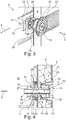
- Fig. 3 Fig. 4 and also Fig. 5 the mode of operation of the compensation mechanism of different thermal expansions of a support structure 3 of the support frame 33 and surface structure 2 of a wall panel 32 is graphically illustrated.
- the connecting device 10 comprising suitable connecting means 13, a surface structure 2 and a support structure 3 are pressed onto one another with an assembly normal force F in an axial direction 5 of the connecting device 10 and are thus fastened to one another.
- the normal assembly force F generates an adhesive force H acting in the longitudinal direction, which results in a frictional connection between the supporting structure 3 and the surface structure 2.
- the connecting means 13 can be designed as a screw with a screw head 14 and a screw nut 16, so that the normal assembly force F is generated between the screw nut 16 and the screw head 14.
- the surface structure 2 is firmly connected at the fastening point 6 and at at least one connection point 7 to the supporting framework 33 or to a corresponding supporting structure 3. For this reason, a different length dilation of the surface structure 2 and the support structure 3 leads to the creation of tension between the structures, which in turn is expressed in a longitudinal expansion force L in the longitudinal direction 4. If the longitudinal expansion force L exceeds the adhesive force H, the more strongly expanding support structure 3 begins to move at the corresponding connection point 7 with respect to the surface structure 2. In particular, the longitudinal expansion force L exceeds the adhesive force H when the structures 2 and 3 heat up by at least 60 ° K.
- the connecting device 10 has a device section 11 on the surface structure side, in particular having a screw nut 16, and a device portion 12 on the support structure side, in particular having the screw head 14, which is inserted into a receptacle 8 provided for this in the surface structure 2 or into an enlarged receptacle 9 engage the support structure 3.
- the enlarged receptacle 9 of the support structure 3 is designed in the form of an elongated hole extending in the longitudinal direction 4, into which the support structure-side device section 12 of the connecting device 10 can engage with play in the longitudinal direction 4.
- the connecting device 10 is received in the enlarged receptacle 9 via the device section 12 on the support structure side so as to be displaceable in the longitudinal direction 4.
- connecting device 10 can only be displaced in the enlarged receptacle 9 or is under play within the scope of the thermal dilation compensation. In normal, atmospheric operation, there is a fixed, different connection between the connecting device 10 and the enlarged receptacle 9 of the support structure 3.
- the screw nut 16 of the device section 12 on the support structure side can be provided with two flattened, parallel and opposite radial flanks 27.
- the distance between these radial flanks 27 corresponds to the width of the elongated hole perpendicular to the longitudinal direction 4, the enlarged receptacle having sliding flanks 18 corresponding to the radial flanks 27 on these.
- a component corresponding to the screw nut 16 would also have corresponding radial flanks 27.
- the connecting device 10 comprises a first axial stop 15 and a second axial stop 17, which are provided to introduce the assembly prestressing force F into the support structure 3 and into the surface structure 2 in the axial direction 5.
- the device section 12 on the support structure side, in particular the screw nut 16, is provided with a second axial stop 17, via which forces effective in the axial direction 5 can be transmitted from the screw nut 16 to the support structure 3.
- the screw nut 16 can be inserted into the enlarged receptacle 9 with the radial flanks 27 in the axial direction 5 until the second axial stop 17 is in contact.
- the screw nut 16 can thus be displaced in the longitudinal direction 4 between the sliding flanks 18, the radial flanks 27 being guided by the sliding flanks 18.
- the connecting means 13 are designed as a screw that can be screwed into the screw nut 16.
- the assembly prestressing force F is transmitted via a screw head 14 with a washer to a damping element 22 - preferably made of wire wool braiding - and then to a pot 23.
- the assembly prestressing force F can be entered from the pot base 24 via the pot shoulder 25 onto an axial surface section of the surface structure 3.
- a sealing element 20 is arranged between the support structure 3 and the surface structure 2 in order to make it more difficult or to prevent an undesired gas transfer between the interior 34 and the surroundings.
- a clamping ring 26 can be provided between the support structure 3 and the surface structure 2.
- a spacer sleeve 19 surrounds the connecting means 13 and thus ensures a minimal clamping distance between the first axial stop 15 and the second axial stop 17.
- the material properties and design between the first and second axial stops 15 and 17 as well as the clamping distance determine the level of the pre-tensioning force F.
- the support frame 33 which is composed of the several support structures 3, can, according to one embodiment, contain further different compensation devices 40a, 40b and 40c.
- These compensation devices 40a, 40b, 40c enable thermal expansions of support structures 3a, 3b, 3c to be compensated for with one another. In this way, non-uniform thermal expansion due to non-uniform local heating of the supporting framework 33 within the same can be absorbed.
- a first compensation device 40a is provided on a supporting structure 3a, effective between a first structural part 35 and a second structural part 36 of the supporting structure 3a, and serves to compensate for a length dilation caused by thermal expansion of the supporting structure 3a.
- a thermal expansion of the supporting structure 3 a arranged in the corner of the fire protection cabinet 30 - shown in detail in FIG Fig. 6 - instead of this support structure 3a in the longitudinal direction 4a, this expansion can be compensated for by compressing the support structure 3a.
- the compensation device 40a is provided with a connecting device 41, a prestressing element and an elongated hole 42.
- the prestressing element 43 presses the first structural part 35 according to a certain prestressing force perpendicular to the longitudinal direction 4a onto the second structural part 36. If an expansion force - analogously to what was said above - exceeds the adhesive force caused by the prestressing force between the structural parts 35 and 36, these structural parts 35 shift , 36 to each other and compensate for the length dilation.
- the elongated hole 42 and a projection correspondingly formed therein make it possible to maintain the shape of the support structure 3a in the longitudinal direction 4a.
- a second compensation device 40b is shown in FIG Fig. 7 shown, this being provided at a corner connection of the supporting frame 33.
- a structural part 38 of a support structure 3b is attached to an angle piece 37.
- a pretensioning element 43 is used here, so that a longitudinal expansion force L caused by length dilation is compensated for by compressing the structural part 38 with the angle piece 37 in the longitudinal direction 4b.
- a T-connection of a T-structural part 3c with a further structural part 3 is designed in a similar manner ( Fig. 8 ).
- a connection has a third compensation device 40c, as a result of which the T-structural part 3c abutting perpendicularly on the further structural part 3 is pretensioned and displaceable in the longitudinal direction 4c the further structural part 3 is arranged.
- the position of the T-structural part 3c in the longitudinal direction 4c of the further structural part 3 can be maintained.
Landscapes
- Engineering & Computer Science (AREA)
- Mechanical Engineering (AREA)
- Transportation (AREA)
- Life Sciences & Earth Sciences (AREA)
- Wood Science & Technology (AREA)
- Casings For Electric Apparatus (AREA)
Claims (14)
- Système de fixation (1) présentant- une première structure conçue en tant que structure de surface (2) s'étendant dans une direction longitudinale (4), une seconde structure conçue en tant que structure de support (3) pour supporter la structure de surface (2), s'étendant au moins dans la direction longitudinale (4) et disposée parallèlement à la première structure par rapport à la direction longitudinale (4), et un dispositif de liaison (10) faisant saillie perpendiculairement aux structures dans une direction axiale (5),- les structures étant fabriquées à partir de matériaux différents avec des coefficients de dilatation thermique différents,- les structures étant fixées l'une à l'autre à un point de fixation (6) et étant également reliées l'une à l'autre à un point de liaison (7), décalé dans la direction longitudinale (4) par rapport au point de fixation (6), au moyen du dispositif de liaison (10) par la fourniture d'une force normale de montage (F) déterminée et effective entre les structures,- les structures présentant chacune dans la zone du point de liaison (7) un réceptacle (8, 9) pour recevoir chacune une section de dispositif (11, 12) du dispositif de liaison (10),- l'un des réceptacles (9) étant plus grand dans la direction longitudinale (4) que la section de dispositif (12) disposée dans ledit réceptacle agrandi (9), de sorte que le dispositif de liaison (10) est disposé de manière déplaçable dans la structure correspondante dans la direction longitudinale (4),- le dispositif de liaison (10) présentant des moyens de liaison (13) comportant une première butée axiale (15), une seconde butée axiale (17) qui peut être positionnée axialement dans la direction axiale (5) du dispositif de liaison (10), une douille entretoise (19), un élément d'étanchéité agissant axialement (20) et un élément de tension (21), et- dans l'état monté, la douille entretoise (19) étant disposée entre les butées axiales (15, 17) et venant en prise autour des moyens de liaison (13) de telle sorte que le dispositif de liaison (10), à l'état monté, forme et assure une distance de serrage axiale minimale entre les butées axiales (15, 17), l'élément d'étanchéité (20) étant disposé entre la structure de support (3) et la structure de surface (2), et l'élément de tension (21) étant disposé entre la première butée axiale (15) et l'élément de surface (2) pour transmettre la force normale de montage (F).
- Système de fixation (1) selon la revendication 1, présentant un autre dispositif de liaison (10), dans lequel le point de fixation est conçu en tant qu'autre point de liaison (7) et dans lequel les structures sont reliées l'une à l'autre à l'autre point de liaison (7) au moyen de l'autre dispositif de liaison (10).
- Système de fixation (1) selon la revendication 1 ou 2,- dans lequel au moins le dispositif de liaison (10) et les structures sont conçus géométriquement de telle sorte, et ont des caractéristiques d'élasticité telles, qu'à l'état monté, la force normale de montage (F) déterminée est générée entre les structures, et- dans lequel le système tribologique est conçu entre la première structure, la seconde structure, le dispositif de liaison (10), et/ou le réceptacle agrandi (9) de telle sorte que, suite à un changement de température des structures d'au moins 60 °K, en particulier 80 °K, et de préférence 100 °K, une force de dilatation longitudinale induite thermiquement (L) agissant entre les structures est supérieure à une force adhésive (H) provoquée par la force normale de montage (F).
- Système de fixation (1) selon l'une des revendications précédentes, dans lequel, à l'état monté, la force normale de montage (F) est générée en fournissant la distance de serrage entre les butées axiales et en comprimant ensemble l'élément de tension (21), la structure de surface (2), l'élément d'étanchéité (19) et la structure de support (3) entre les butées axiales (15, 17) sur la distance de serrage.
- Système de fixation (1) selon l'une des revendications précédentes, dans lequel le dispositif de liaison (10) présente une bague de serrage (26) qui est disposée dans la direction axiale (5) parallèlement à l'élément d'étanchéité (19).
- Système de fixation (1) selon l'une des revendications précédentes, dans lequel l'élément de tension (21) présente un élément d'amortissement (22), en particulier réalisé sous forme de coussin entièrement métallique, et un pot (23) comportant un fond de pot (24) pour recevoir l'élément d'amortissement (22) et un épaulement de pot (25) pour introduire la force normale de montage (F) dans la structure de surface (2), l'élément d'amortissement (22) étant appuyé dans la direction axiale (5) contre la première butée axiale (15) et le fond de pot (24).
- Système de fixation (1) selon la revendication 6, dans lequel le pot (23) présente une forme similaire à un cône tronqué.
- Système de fixation (1) selon l'une des revendications précédentes, dans lequel l'élément d'étanchéité (20) présente un matériau intumescent.
- Système de fixation (1) selon l'une des revendications précédentes, dans lequel le réceptacle élargi (9) est prévu dans la structure de support (3) et forme, perpendiculairement à la direction longitudinale (4), une distance de coulissement sensiblement constante dans la direction longitudinale (4) du réceptacle agrandi, la section de dispositif (12) du dispositif de raccordement (10) reçue dans le réceptacle agrandi (9) présentant deux flancs de coulissement (18) correspondant au réceptacle agrandi (9), de telle sorte que la section de dispositif (12) est logée dans le réceptacle agrandi (9) de manière non rotative mais déplaçable dans la direction longitudinale (4).
- Système de fixation (1) selon l'une des revendications précédentes, dans lequel un coefficient de dilatation thermique de la structure de surface (2), en particulier dans la direction longitudinale (4), est inférieur à 13 x 10-6 Kelvin puissance moins un, en particulier inférieur à 12,5 x 10⁻⁶ Kelvin puissance moins un, et/ou inférieur à 12 x 10-6 Kelvin puissance moins un, et/ou un coefficient de dilatation thermique de la structure de support (4), en particulier dans la direction longitudinale (4), est supérieur à 13 x 10-6 Kelvin puissance moins un, en particulier supérieur à 13,1 x 10⁻⁶ Kelvin puissance moins un, et/ou supérieur à 13,5 x 10⁻⁶ Kelvin puissance moins un, et en particulier inférieur à 16,6 x 10⁻⁶ Kelvin puissance moins un.
- Armoire de protection contre l'incendie (30) permettant de recevoir des composants électriques, présentant au moins une armature (33) et des panneaux muraux (32) fixés sur celle-ci,- dans laquelle l'ensemble des panneaux muraux (32) définit un espace intérieur (34) de l'armoire de protection contre l'incendie (30), et en particulier l'armature (33) est prévue dans l'espace intérieur (34),- l'armature (33) et les panneaux muraux (32) sont formés d'au moins un système de fixation (1) selon l'une des revendications précédentes de telle sorte que l'armature (33) présente au moins une pluralité de structures de support (3) et un panneau mural (32) présente au moins une structure de surface (2), un panneau mural (32) étant fixé de manière déplaçable à une structure de support (3) correspondante de l'armature (33) dans la direction longitudinale (4) d'une structure de support (3) selon son réceptacle élargi (9), et- la structure de surface (2) étant fabriquée à partir d'un matériau incombustible, ignifuge et/ou structurellement fixe, en particulier à partir d'un matériau incombustible jusqu'à une température ambiante de 783 °C.
- Armoire de protection contre l'incendie (30) selon la revendication 11, présentant au moins un dispositif de compensation (40a, 40b, 40c) permettant de compenser une dilatation thermique en longueur d'une structure de support (2, 31), dans laquelle le dispositif de compensation (40a, 40b, 40c) est disposé à l'intérieur d'une structure de support (2; 31) et/ou entre deux structures de support (2, 31).
- Armoire de protection contre l'incendie (30) selon la revendication 12, dans laquelle le dispositif de compensation (40) présente au moins un dispositif de liaison précontraint (41), lequel est disposé entre deux parties de structure (35, 36) d'une structure de support (31) et/ou entre deux structures de support (2, 31) pour générer une force normale de montage, et au moins une partie de structure (35, 36) et/ou au moins une des structures de support (2, 31) présentant un trou oblong (42) pour recevoir le dispositif de liaison (41).
- Moyen de transport, en particulier véhicule, véhicule ferroviaire (100) ou avion, présentant une armoire de protection contre l'incendie (30) selon les revendications 11 à 13.
Applications Claiming Priority (1)
| Application Number | Priority Date | Filing Date | Title |
|---|---|---|---|
| DE102017111965.5A DE102017111965A1 (de) | 2017-05-31 | 2017-05-31 | Verbundsystem, Feuerschutzschrank und Transportmittel aufweisend einen Feuerschutzschrank |
Publications (2)
| Publication Number | Publication Date |
|---|---|
| EP3409556A1 EP3409556A1 (fr) | 2018-12-05 |
| EP3409556B1 true EP3409556B1 (fr) | 2021-08-18 |
Family
ID=62620634
Family Applications (1)
| Application Number | Title | Priority Date | Filing Date |
|---|---|---|---|
| EP18174620.7A Active EP3409556B1 (fr) | 2017-05-31 | 2018-05-28 | Système de fixation, armoire de protection contre l'incendie et moyen de transport comportant une armoire de protection contre l'incendie |
Country Status (2)
| Country | Link |
|---|---|
| EP (1) | EP3409556B1 (fr) |
| DE (1) | DE102017111965A1 (fr) |
Families Citing this family (5)
| Publication number | Priority date | Publication date | Assignee | Title |
|---|---|---|---|---|
| CN112389475B (zh) * | 2020-11-18 | 2023-03-21 | 中车唐山机车车辆有限公司 | 车厢及轨道车辆 |
| CN112670872B (zh) * | 2021-02-01 | 2022-05-17 | 电管家能源管理(上海)有限公司 | 一种高低压配电柜 |
| CN112971401B (zh) * | 2021-03-05 | 2022-11-29 | 江西金虎保险设备集团有限公司 | 一种防火防湿多功能储存柜 |
| CN115604955B (zh) * | 2022-10-24 | 2023-12-22 | 江苏联成开拓集团有限公司 | 一种自动驾驶用控制器 |
| CN116454747B (zh) * | 2023-04-25 | 2024-01-09 | 国网安徽省电力有限公司阜阳供电公司 | 一种具有耐火膨胀填充结构的高压设备柜 |
Family Cites Families (9)
| Publication number | Priority date | Publication date | Assignee | Title |
|---|---|---|---|---|
| AT164921B (de) * | 1947-04-16 | 1949-12-27 | Albert Linke | Feuersicherer Schrank für Akten u. dgl. |
| CH431854A (de) * | 1964-04-21 | 1967-03-15 | Rohrer Gmbh Geb | Zerlegbares Möbel |
| FR2473592A1 (fr) * | 1980-01-10 | 1981-07-17 | Saint Gobain Vitrage | Chassis metallique pour cloison vitree coupe-feu et cloison vitree comportant un tel chassis |
| US4650385A (en) * | 1983-05-17 | 1987-03-17 | The United States Of America As Represented By The Administrator Of The National Aeronautics And Space Administration | Daze fasteners |
| DE29615124U1 (de) * | 1996-08-30 | 1996-10-31 | Urbat Peter | Trägersystem |
| GB0323795D0 (en) * | 2003-10-10 | 2003-11-12 | Bombardier Transp Gmbh | Fire protection wall |
| DE102004033536B4 (de) * | 2004-07-09 | 2006-11-23 | Boris Schubert | Gehäuse aus feuerhemmendem Material |
| DE102012207013A1 (de) * | 2012-04-27 | 2013-10-31 | Siemens Aktiengesellschaft | Belüftung eines elektrischen Gerätes |
| DE102013214247A1 (de) * | 2013-07-22 | 2015-01-22 | Bayerische Motoren Werke Aktiengesellschaft | Blindnietmutter für die Verbindung zweier Bauteile |
-
2017
- 2017-05-31 DE DE102017111965.5A patent/DE102017111965A1/de not_active Ceased
-
2018
- 2018-05-28 EP EP18174620.7A patent/EP3409556B1/fr active Active
Non-Patent Citations (1)
| Title |
|---|
| None * |
Also Published As
| Publication number | Publication date |
|---|---|
| EP3409556A1 (fr) | 2018-12-05 |
| DE102017111965A1 (de) | 2018-12-06 |
Similar Documents
| Publication | Publication Date | Title |
|---|---|---|
| EP3409556B1 (fr) | Système de fixation, armoire de protection contre l'incendie et moyen de transport comportant une armoire de protection contre l'incendie | |
| EP2594452B1 (fr) | Dispositif d'embrayage pour la zone frontale d'un véhicule guidé sur rails | |
| EP1752353B1 (fr) | Dispositif d'absorption d'énergie à force de réaction élevée | |
| EP2072370B1 (fr) | Dispositif d'absorption d'énergie pour une caisse d'un véhicule composé de plusieurs unités | |
| EP1990251B1 (fr) | Dispositif d'absorption d'énergie pour véhicules à éléments multiples | |
| EP1832690B1 (fr) | Elément de construction pour isolation thermique | |
| EP2532273B1 (fr) | Elément de fixation | |
| EP1857342A1 (fr) | Dispositif d'accouplement avec dispositif de sécurité antisurcharge | |
| EP1535816A1 (fr) | Attelage central pour véhicules ferroviaires | |
| DE4302444A1 (de) | Automatische Mittelpufferkupplung | |
| EP3325837B1 (fr) | Outil de montage d'un étrier de retenue de plaquette de frein muni d'un dispositif de fixation d'un frein à disque, frein à disque et jeu de plaquettes de frein | |
| EP1526981B1 (fr) | Systeme de securite pour sieges de vehicule | |
| DE102007013509A1 (de) | Befestigungsvorrichtung | |
| EP2130993B1 (fr) | Dispositif d'appui, notamment chandelle | |
| DE102014108979B4 (de) | Vorrichtung zur Absorption von Energie bei einem Fahrzeugaufprall | |
| DE202016106796U1 (de) | Fahrzeugsitz | |
| DE102017201356A1 (de) | Sitzträger für einen Fahrzeugsitz | |
| EP0628734A1 (fr) | Dispositif de fixation pour relier de manière amovible un tube polygonal, en particulier un tube à profil rectangulaire | |
| EP3530544A1 (fr) | Dispositif de déformation pourvu de protection anti-chevauchement pour véhicules ferroviaires | |
| AT511290A1 (de) | Schienenfahrzeug mit verformungszone | |
| DE102014004440A1 (de) | Sitzstruktur für einen Fahrzeugsitz, insbesondere eines Kraftwagens | |
| EP0900689A1 (fr) | Support pour un siège de véhicule, en particulier une banquette arrière réglable longitudinalement | |
| EP3658419B1 (fr) | Dispositif de protection des piétons pour un véhicule | |
| DE102013016534B3 (de) | Lenksäulenanordnung für einen Kraftwagen | |
| DE69721434T2 (de) | Kupplungssyteme für Schienenfahrzeuge |
Legal Events
| Date | Code | Title | Description |
|---|---|---|---|
| PUAI | Public reference made under article 153(3) epc to a published international application that has entered the european phase |
Free format text: ORIGINAL CODE: 0009012 |
|
| STAA | Information on the status of an ep patent application or granted ep patent |
Free format text: STATUS: THE APPLICATION HAS BEEN PUBLISHED |
|
| AK | Designated contracting states |
Kind code of ref document: A1 Designated state(s): AL AT BE BG CH CY CZ DE DK EE ES FI FR GB GR HR HU IE IS IT LI LT LU LV MC MK MT NL NO PL PT RO RS SE SI SK SM TR |
|
| AX | Request for extension of the european patent |
Extension state: BA ME |
|
| STAA | Information on the status of an ep patent application or granted ep patent |
Free format text: STATUS: REQUEST FOR EXAMINATION WAS MADE |
|
| 17P | Request for examination filed |
Effective date: 20190604 |
|
| RBV | Designated contracting states (corrected) |
Designated state(s): AL AT BE BG CH CY CZ DE DK EE ES FI FR GB GR HR HU IE IS IT LI LT LU LV MC MK MT NL NO PL PT RO RS SE SI SK SM TR |
|
| STAA | Information on the status of an ep patent application or granted ep patent |
Free format text: STATUS: EXAMINATION IS IN PROGRESS |
|
| 17Q | First examination report despatched |
Effective date: 20200416 |
|
| STAA | Information on the status of an ep patent application or granted ep patent |
Free format text: STATUS: EXAMINATION IS IN PROGRESS |
|
| GRAP | Despatch of communication of intention to grant a patent |
Free format text: ORIGINAL CODE: EPIDOSNIGR1 |
|
| STAA | Information on the status of an ep patent application or granted ep patent |
Free format text: STATUS: GRANT OF PATENT IS INTENDED |
|
| INTG | Intention to grant announced |
Effective date: 20210316 |
|
| GRAS | Grant fee paid |
Free format text: ORIGINAL CODE: EPIDOSNIGR3 |
|
| GRAA | (expected) grant |
Free format text: ORIGINAL CODE: 0009210 |
|
| STAA | Information on the status of an ep patent application or granted ep patent |
Free format text: STATUS: THE PATENT HAS BEEN GRANTED |
|
| AK | Designated contracting states |
Kind code of ref document: B1 Designated state(s): AL AT BE BG CH CY CZ DE DK EE ES FI FR GB GR HR HU IE IS IT LI LT LU LV MC MK MT NL NO PL PT RO RS SE SI SK SM TR |
|
| REG | Reference to a national code |
Ref country code: GB Ref legal event code: FG4D Free format text: NOT ENGLISH |
|
| REG | Reference to a national code |
Ref country code: CH Ref legal event code: EP |
|
| REG | Reference to a national code |
Ref country code: DE Ref legal event code: R096 Ref document number: 502018006608 Country of ref document: DE |
|
| REG | Reference to a national code |
Ref country code: IE Ref legal event code: FG4D Free format text: LANGUAGE OF EP DOCUMENT: GERMAN Ref country code: AT Ref legal event code: REF Ref document number: 1421392 Country of ref document: AT Kind code of ref document: T Effective date: 20210915 |
|
| REG | Reference to a national code |
Ref country code: LT Ref legal event code: MG9D |
|
| REG | Reference to a national code |
Ref country code: NL Ref legal event code: MP Effective date: 20210818 |
|
| PG25 | Lapsed in a contracting state [announced via postgrant information from national office to epo] |
Ref country code: PT Free format text: LAPSE BECAUSE OF FAILURE TO SUBMIT A TRANSLATION OF THE DESCRIPTION OR TO PAY THE FEE WITHIN THE PRESCRIBED TIME-LIMIT Effective date: 20211220 Ref country code: NO Free format text: LAPSE BECAUSE OF FAILURE TO SUBMIT A TRANSLATION OF THE DESCRIPTION OR TO PAY THE FEE WITHIN THE PRESCRIBED TIME-LIMIT Effective date: 20211118 Ref country code: LT Free format text: LAPSE BECAUSE OF FAILURE TO SUBMIT A TRANSLATION OF THE DESCRIPTION OR TO PAY THE FEE WITHIN THE PRESCRIBED TIME-LIMIT Effective date: 20210818 Ref country code: BG Free format text: LAPSE BECAUSE OF FAILURE TO SUBMIT A TRANSLATION OF THE DESCRIPTION OR TO PAY THE FEE WITHIN THE PRESCRIBED TIME-LIMIT Effective date: 20211118 Ref country code: SE Free format text: LAPSE BECAUSE OF FAILURE TO SUBMIT A TRANSLATION OF THE DESCRIPTION OR TO PAY THE FEE WITHIN THE PRESCRIBED TIME-LIMIT Effective date: 20210818 Ref country code: RS Free format text: LAPSE BECAUSE OF FAILURE TO SUBMIT A TRANSLATION OF THE DESCRIPTION OR TO PAY THE FEE WITHIN THE PRESCRIBED TIME-LIMIT Effective date: 20210818 Ref country code: HR Free format text: LAPSE BECAUSE OF FAILURE TO SUBMIT A TRANSLATION OF THE DESCRIPTION OR TO PAY THE FEE WITHIN THE PRESCRIBED TIME-LIMIT Effective date: 20210818 Ref country code: ES Free format text: LAPSE BECAUSE OF FAILURE TO SUBMIT A TRANSLATION OF THE DESCRIPTION OR TO PAY THE FEE WITHIN THE PRESCRIBED TIME-LIMIT Effective date: 20210818 Ref country code: FI Free format text: LAPSE BECAUSE OF FAILURE TO SUBMIT A TRANSLATION OF THE DESCRIPTION OR TO PAY THE FEE WITHIN THE PRESCRIBED TIME-LIMIT Effective date: 20210818 |
|
| PG25 | Lapsed in a contracting state [announced via postgrant information from national office to epo] |
Ref country code: PL Free format text: LAPSE BECAUSE OF FAILURE TO SUBMIT A TRANSLATION OF THE DESCRIPTION OR TO PAY THE FEE WITHIN THE PRESCRIBED TIME-LIMIT Effective date: 20210818 Ref country code: LV Free format text: LAPSE BECAUSE OF FAILURE TO SUBMIT A TRANSLATION OF THE DESCRIPTION OR TO PAY THE FEE WITHIN THE PRESCRIBED TIME-LIMIT Effective date: 20210818 Ref country code: GR Free format text: LAPSE BECAUSE OF FAILURE TO SUBMIT A TRANSLATION OF THE DESCRIPTION OR TO PAY THE FEE WITHIN THE PRESCRIBED TIME-LIMIT Effective date: 20211119 |
|
| PG25 | Lapsed in a contracting state [announced via postgrant information from national office to epo] |
Ref country code: NL Free format text: LAPSE BECAUSE OF FAILURE TO SUBMIT A TRANSLATION OF THE DESCRIPTION OR TO PAY THE FEE WITHIN THE PRESCRIBED TIME-LIMIT Effective date: 20210818 |
|
| PG25 | Lapsed in a contracting state [announced via postgrant information from national office to epo] |
Ref country code: DK Free format text: LAPSE BECAUSE OF FAILURE TO SUBMIT A TRANSLATION OF THE DESCRIPTION OR TO PAY THE FEE WITHIN THE PRESCRIBED TIME-LIMIT Effective date: 20210818 |
|
| REG | Reference to a national code |
Ref country code: DE Ref legal event code: R097 Ref document number: 502018006608 Country of ref document: DE |
|
| PG25 | Lapsed in a contracting state [announced via postgrant information from national office to epo] |
Ref country code: SM Free format text: LAPSE BECAUSE OF FAILURE TO SUBMIT A TRANSLATION OF THE DESCRIPTION OR TO PAY THE FEE WITHIN THE PRESCRIBED TIME-LIMIT Effective date: 20210818 Ref country code: SK Free format text: LAPSE BECAUSE OF FAILURE TO SUBMIT A TRANSLATION OF THE DESCRIPTION OR TO PAY THE FEE WITHIN THE PRESCRIBED TIME-LIMIT Effective date: 20210818 Ref country code: RO Free format text: LAPSE BECAUSE OF FAILURE TO SUBMIT A TRANSLATION OF THE DESCRIPTION OR TO PAY THE FEE WITHIN THE PRESCRIBED TIME-LIMIT Effective date: 20210818 Ref country code: EE Free format text: LAPSE BECAUSE OF FAILURE TO SUBMIT A TRANSLATION OF THE DESCRIPTION OR TO PAY THE FEE WITHIN THE PRESCRIBED TIME-LIMIT Effective date: 20210818 Ref country code: CZ Free format text: LAPSE BECAUSE OF FAILURE TO SUBMIT A TRANSLATION OF THE DESCRIPTION OR TO PAY THE FEE WITHIN THE PRESCRIBED TIME-LIMIT Effective date: 20210818 Ref country code: AL Free format text: LAPSE BECAUSE OF FAILURE TO SUBMIT A TRANSLATION OF THE DESCRIPTION OR TO PAY THE FEE WITHIN THE PRESCRIBED TIME-LIMIT Effective date: 20210818 |
|
| PLBE | No opposition filed within time limit |
Free format text: ORIGINAL CODE: 0009261 |
|
| STAA | Information on the status of an ep patent application or granted ep patent |
Free format text: STATUS: NO OPPOSITION FILED WITHIN TIME LIMIT |
|
| 26N | No opposition filed |
Effective date: 20220519 |
|
| PG25 | Lapsed in a contracting state [announced via postgrant information from national office to epo] |
Ref country code: IT Free format text: LAPSE BECAUSE OF FAILURE TO SUBMIT A TRANSLATION OF THE DESCRIPTION OR TO PAY THE FEE WITHIN THE PRESCRIBED TIME-LIMIT Effective date: 20210818 |
|
| PG25 | Lapsed in a contracting state [announced via postgrant information from national office to epo] |
Ref country code: SI Free format text: LAPSE BECAUSE OF FAILURE TO SUBMIT A TRANSLATION OF THE DESCRIPTION OR TO PAY THE FEE WITHIN THE PRESCRIBED TIME-LIMIT Effective date: 20210818 |
|
| REG | Reference to a national code |
Ref country code: CH Ref legal event code: PL |
|
| REG | Reference to a national code |
Ref country code: BE Ref legal event code: MM Effective date: 20220531 |
|
| GBPC | Gb: european patent ceased through non-payment of renewal fee |
Effective date: 20220528 |
|
| PG25 | Lapsed in a contracting state [announced via postgrant information from national office to epo] |
Ref country code: MC Free format text: LAPSE BECAUSE OF FAILURE TO SUBMIT A TRANSLATION OF THE DESCRIPTION OR TO PAY THE FEE WITHIN THE PRESCRIBED TIME-LIMIT Effective date: 20210818 Ref country code: LU Free format text: LAPSE BECAUSE OF NON-PAYMENT OF DUE FEES Effective date: 20220528 Ref country code: LI Free format text: LAPSE BECAUSE OF NON-PAYMENT OF DUE FEES Effective date: 20220531 Ref country code: CH Free format text: LAPSE BECAUSE OF NON-PAYMENT OF DUE FEES Effective date: 20220531 |
|
| PG25 | Lapsed in a contracting state [announced via postgrant information from national office to epo] |
Ref country code: IE Free format text: LAPSE BECAUSE OF NON-PAYMENT OF DUE FEES Effective date: 20220528 |
|
| PG25 | Lapsed in a contracting state [announced via postgrant information from national office to epo] |
Ref country code: GB Free format text: LAPSE BECAUSE OF NON-PAYMENT OF DUE FEES Effective date: 20220528 Ref country code: BE Free format text: LAPSE BECAUSE OF NON-PAYMENT OF DUE FEES Effective date: 20220531 |
|
| PGFP | Annual fee paid to national office [announced via postgrant information from national office to epo] |
Ref country code: FR Payment date: 20230526 Year of fee payment: 6 Ref country code: DE Payment date: 20230519 Year of fee payment: 6 |
|
| P01 | Opt-out of the competence of the unified patent court (upc) registered |
Effective date: 20230822 |
|
| PG25 | Lapsed in a contracting state [announced via postgrant information from national office to epo] |
Ref country code: HU Free format text: LAPSE BECAUSE OF FAILURE TO SUBMIT A TRANSLATION OF THE DESCRIPTION OR TO PAY THE FEE WITHIN THE PRESCRIBED TIME-LIMIT; INVALID AB INITIO Effective date: 20180528 |
|
| PG25 | Lapsed in a contracting state [announced via postgrant information from national office to epo] |
Ref country code: MK Free format text: LAPSE BECAUSE OF FAILURE TO SUBMIT A TRANSLATION OF THE DESCRIPTION OR TO PAY THE FEE WITHIN THE PRESCRIBED TIME-LIMIT Effective date: 20210818 Ref country code: CY Free format text: LAPSE BECAUSE OF FAILURE TO SUBMIT A TRANSLATION OF THE DESCRIPTION OR TO PAY THE FEE WITHIN THE PRESCRIBED TIME-LIMIT Effective date: 20210818 |