EP3409540B1 - Spiegelersatz- oder spiegelergänzungskonstruktion mit positionierungserkennung - Google Patents
Spiegelersatz- oder spiegelergänzungskonstruktion mit positionierungserkennung Download PDFInfo
- Publication number
- EP3409540B1 EP3409540B1 EP18171970.9A EP18171970A EP3409540B1 EP 3409540 B1 EP3409540 B1 EP 3409540B1 EP 18171970 A EP18171970 A EP 18171970A EP 3409540 B1 EP3409540 B1 EP 3409540B1
- Authority
- EP
- European Patent Office
- Prior art keywords
- motor vehicle
- holding device
- operational position
- camera
- nbp
- Prior art date
- Legal status (The legal status is an assumption and is not a legal conclusion. Google has not performed a legal analysis and makes no representation as to the accuracy of the status listed.)
- Active
Links
- 238000001514 detection method Methods 0.000 title claims description 18
- 230000001502 supplementing effect Effects 0.000 title 1
- 230000004913 activation Effects 0.000 claims description 10
- 230000003213 activating effect Effects 0.000 claims 1
- 238000010276 construction Methods 0.000 description 5
- 230000005540 biological transmission Effects 0.000 description 2
- 238000011161 development Methods 0.000 description 2
- 230000018109 developmental process Effects 0.000 description 2
- 230000001419 dependent effect Effects 0.000 description 1
- 238000005265 energy consumption Methods 0.000 description 1
- 238000012986 modification Methods 0.000 description 1
- 230000004048 modification Effects 0.000 description 1
Images

Classifications
-
- B—PERFORMING OPERATIONS; TRANSPORTING
- B60—VEHICLES IN GENERAL
- B60R—VEHICLES, VEHICLE FITTINGS, OR VEHICLE PARTS, NOT OTHERWISE PROVIDED FOR
- B60R11/00—Arrangements for holding or mounting articles, not otherwise provided for
- B60R11/04—Mounting of cameras operative during drive; Arrangement of controls thereof relative to the vehicle
Definitions
- the invention relates to a device, in particular a mirror replacement construction, with a mounting device for arrangement on a motor vehicle, the mounting device having at least one camera, expediently for capturing an area to the side of and/or behind the motor vehicle.
- the invention also relates to a motor vehicle with at least one such device.
- Mirror replacement designs for motor vehicles are already known in the prior art. They usually include a mounting device with a camera for mounting on the motor vehicle.
- the camera is expediently used to capture an area to the side of and behind the motor vehicle, with a display in the vehicle serving to show the captured area to the driver of the motor vehicle.
- a disadvantage of such mirror replacement constructions is that the mounting device and thus the camera z. B. can be transported at least slightly from its proper operating position by a collision with another object, which is not immediately apparent to the driver of the motor vehicle in some cases.
- An improperly aligned camera harbors the risk that the camera can no longer capture all relevant areas to the side of and behind the motor vehicle.
- the invention relates to a device, namely a mirror replacement construction with a mounting device for arrangement on a motor vehicle, e.g. B. a commercial vehicle, such as a truck or a bus.
- a motor vehicle e.g. B. a commercial vehicle, such as a truck or a bus.
- the mounting device includes at least one camera for capturing (eg recording) an area expediently to the side next to and/or behind the motor vehicle.
- the device is characterized in particular by the fact that it has at least one detection device for detecting whether the mounting device and thus expediently the at least one camera is arranged on the motor vehicle in a non-operating position (e.g. non-operating orientation) and the non- Operating position (NBP) includes an incorrect position, wherein the detection device comprises at least one sensor, switch or button.
- a non-operating position e.g. non-operating orientation
- NBP non- Operating position
- the detection device is therefore preferably used to detect whether the holding device is arranged in the operating position (e.g. normal position/alignment) or outside of the operating position.
- the at least one detection device is used to detect whether the mounting device and thus expediently the at least one camera is arranged in an operating position (e.g. operating orientation) on the motor vehicle.
- the mounting device prefferably via a rotary or swivel joint, for assembly on the motor vehicle so that it can be folded in and out.
- the operating position can expediently include a functionally aligned and/or properly unfolded position (e.g. alignment) of the mounting device, in which preferably the at least one camera for capturing the area is expediently correctly aligned laterally next to and/or behind the motor vehicle.
- a functionally aligned and/or properly unfolded position e.g. alignment
- the at least one camera for capturing the area is expediently correctly aligned laterally next to and/or behind the motor vehicle.
- the non-operating position may suitably include an incorrect position (e.g. misalignment) of the mounting device, in which e.g. B. the at least one camera for capturing the area is expediently incorrectly aligned laterally next to and/or behind the motor vehicle, e.g. B. caused by a collision of the mounting device with another object.
- the non-operating position can also include a properly folded position (e.g. alignment) of the mounting device.
- the mounting device prefferably in the form of a holding arm and/or for the detection device to be electrically based.
- the device can have a mounting device, by means of which the mounting device can be mounted on the motor vehicle.
- the device can have a connecting device, by means of which information is provided as to whether the mounting device is arranged in an operating position and/or a non-operating position on the motor vehicle. can be transferred to the motor vehicle.
- the connecting device can e.g. B. include one or more lines, but also z. B. preferably be designed for wireless transmission of information by radio.
- the connecting device can be incorporated into the mounting device, so that the connecting device and the mounting device z. B. can be formed as a unit.
- the connecting device can also be arranged on or in the holding device.
- the mounting device can here z. B. be formed as a base plate, which can be suitably adapted to the geometry of the motor vehicle and can thus be formed substantially flat or curved.
- the invention also includes a motor vehicle, preferably a utility vehicle, such as a bus or a truck, with at least one device as disclosed herein.
- a motor vehicle preferably a utility vehicle, such as a bus or a truck, with at least one device as disclosed herein.
- the motor vehicle prefferably has a device for visually (e.g. by means of a display device such as a display, a monitor, LEDs etc.), acoustically (e.g. via a loudspeaker) and/or a driver of the motor vehicle or to warn haptically (e.g. via a vibration device in the steering wheel or seat) that the mounting device is arranged in the non-operating position on the motor vehicle, and/or to indicate that the mounting device is arranged in the operating position on the motor vehicle.
- a display device such as a display, a monitor, LEDs etc.
- acoustically e.g. via a loudspeaker
- haptically e.g. via a vibration device in the steering wheel or seat
- the mediation ie in particular the warning or notice, before the start of the journey, e.g. B. when the engine of the motor vehicle, or at the start of the journey of the motor vehicle is generated.
- the recognition device can e.g. B. are connected to a display device in the motor vehicle, wherein the display device can be designed to indicate to a driver of the motor vehicle that the mounting device is arranged in an operating position and / or a non-operating position on the motor vehicle.
- the motor vehicle prefferably has a display (e.g. a monitor or another suitable display device) that is operatively connected to the at least one camera for displaying the area captured by the at least one camera.
- a display e.g. a monitor or another suitable display device
- the motor vehicle can, for. B. have an automatic activation function to automatically activate the display and/or the at least one camera when an ignition of the motor vehicle (e.g. so-called terminal 15 "off") is deactivated and a door of the motor vehicle (e.g. Driver and/or passenger door, e.g. a driver's cab of a truck) is opened or closed.
- an ignition of the motor vehicle e.g. so-called terminal 15 "off”
- a door of the motor vehicle e.g. Driver and/or passenger door, e.g. a driver's cab of a truck
- the automatic activation function can be deactivated by a properly folded-in mounting device, so that the display and/or the at least one camera is not activated automatically despite the automatic activation function.
- the display and/or the at least one camera can be deactivated and/or remain deactivated, preferably despite the automatic activation function, if the detection device detects that the mounting device is in the non-operating position, in particular in the properly folded position.
- the feature "camera” is to be interpreted broadly and in particular generally recording devices for recording (expediently recording) z.
- B an area laterally next to and / or behind the motor vehicle.
- detection device is also to be interpreted broadly in the context of the invention and includes in particular devices by means of which it can be recognized, e.g. recorded and/or detected, whether the mounting device is arranged in an operating position and/or a non-operating position on the motor vehicle.
- the detection device is preferably used to detect whether the mounting device is in the operating position (e.g. normal position/position) or outside of the operating position.
- the holding device can be designed as a holding arm (preferably projecting relatively far away from the motor vehicle), but also, e.g. B. as (preferably from the motor vehicle relatively little protruding) camera housing.
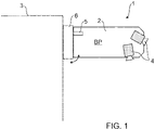
- FIG 1 shows a highly schematic representation of a device 1, in particular a mirror replacement construction with a mounting device 2 for arrangement on a motor vehicle 3.
- the mounting device 2 is shown as a relatively long holding arm, but can also be designed as a relatively compact camera housing.
- the mounting device 2 comprises two cameras 4 for detecting, in particular recording, an area to the side next to and/or behind the motor vehicle 3.
- the mounting device 2 is designed via a rotary or swivel joint for folding and folding assembly on the motor vehicle 3, what in figure 1 is indicated schematically by the double arrow.
- the cameras 4 are operatively connected to a display in the motor vehicle 3 for displaying the area captured by the cameras 4 .
- the device 1 comprises an electrically operating detection device 5 with at least one button or sensor.
- the detection device 5 is designed to detect whether the mounting device 2 and thus the cameras 4 are in an operating position/orientation BP and/or a non-operating position/orientation NBP ( figures 2 and 3 ) is arranged on the motor vehicle 3.
- figure 1 shows the mounting device 2 and thus the cameras 4 in an operating position BP, in particular in a functionally aligned and properly unfolded position.
- the mounting device 2 is mounted on the motor vehicle 3 via a mounting device 6 designed as a base plate.
- a mounting device 6 designed as a base plate.
- the base plate 6 is a connecting device, not shown, for. B. one or more lines, incorporated, on the information whether the support device 2 in an operating position BP and / or a non-operating position NBP is arranged on the motor vehicle 3, in the motor vehicle 3 are transferrable.
- the connection device can also be designed for wireless transmission of the information.
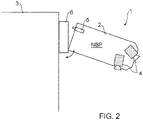
- figure 2 shows a highly schematic representation of the device 1 of FIG figure 1 .
- FIG 2 the mounting device 2 and thus the cameras 4 are shown in a non-operative position NPB, in particular in a faulty position, e.g. B. caused by a collision with another object.
- figure 3 shows a highly schematic representation of the device 1 of FIG figures 1 and 2 .
- FIG 3 the mounting device 2 and thus the cameras 4 are also shown in a non-operative position NPB.
- NPB non-operative position
- FIG 3 show the figure 3 although the mounting device 2 is in a non-operating position NBP, it is in a proper, e.g. B. desired by the driver manually or automatically folded position.
- the information recognized by the recognition device 5 can be used in different ways within the scope of the invention.
- the motor vehicle 3 z. B. have one or more devices, not shown in the figures, to a driver of the motor vehicle 3 optically (e.g. by means of a display device such as a monitor, a display, LEDs, etc.), acoustically (e.g. by means of loudspeakers ) and alternatively or additionally haptically (e.g. by means of a vibration device in the steering wheel or seat) to warn when the mounting device 2 is arranged on the motor vehicle 3 in the non-operating position NBP.
- the driver can be informed in the same way when the mounting device 2 is arranged in the operating position BP on the motor vehicle 3 .
- the warning and / or notice can be expedient before departure, z. B. when the engine starts, or generally generated at the start of the journey.
- the motor vehicle 3 disclosed herein can also meet the aforementioned requirement according to ECE R46 and thus have an automatic activation function in order to activate the cameras 4 and to automatically activate the display for displaying the area captured by the cameras 4 when an ignition of the motor vehicle 3 is deactivated and a door of the motor vehicle 3 is opened or closed.
- the automatic activation function can be deactivated by a properly folded holding device 2 detected by the detection device 5 .
- the system of display and cameras 4 therefore does not have to be activated when the door is opened in the case of a properly folded-in mounting device 2 .
- the driver can thus switch off the automatic activation if necessary by folding in the mounting device 2 . This is useful, for example, in the case of a long standstill (e.g. weekend at a rest stop). This can save energy.
Landscapes
- Engineering & Computer Science (AREA)
- Mechanical Engineering (AREA)
- Fittings On The Vehicle Exterior For Carrying Loads, And Devices For Holding Or Mounting Articles (AREA)
- Rear-View Mirror Devices That Are Mounted On The Exterior Of The Vehicle (AREA)
Description
- Die Erfindung betrifft eine Vorrichtung, insbesondere eine Spiegelersatzkonstruktion mit einer Halterungseinrichtung zur Anordnung an einem Kraftfahrzeug, wobei die Halterungseinrichtung zumindest eine Kamera, zweckmäßig zur Erfassung eines Bereichs seitlich neben und/oder hinter dem Kraftfahrzeug, aufweist. Die Erfindung betrifft auch ein Kraftfahrzeug mit zumindest einer solchen Vorrichtung.
- Spiegelersatzkonstruktionen für Kraftfahrzeuge sind im Stand der Technik bereits bekannt. Sie umfassen üblicherweise eine Halterungseinrichtung mit einer Kamera zur Montage an das Kraftfahrzeug. Die Kamera dient dabei zweckmäßig zur Erfassung eines Bereichs seitlich neben und hinter dem Kraftfahrzeug, wobei ein Display im Kraftfahrzeug dazu dient, den erfassten Bereich für den Fahrer des Kraftfahrzeugs anzuzeigen. Nachteilhaft an derartigen Spiegelersatzkonstruktionen ist, dass die Halterungseinrichtung und somit die Kamera z. B. durch eine Kollision mit einem anderen Objekt zumindest geringfügig aus ihrer ordnungsgemäßen Betriebsposition befördert werden kann, was für den Fahrer des Kraftfahrzeugs in manchen Fällen nicht unmittelbar erkenntlich ist. Eine nicht ordnungsgemäß ausgerichtete Kamera birgt die Gefahr, dass die Kamera nicht mehr alle relevanten Bereiche seitlich neben und hinter dem Kraftfahrzeug erfassen kann.
- Eine Aufgabe der Erfindung ist es deshalb, eine Vorrichtung der eingangs beschriebenen Art zu schaffen, welche insbesondere hohen Sicherheitsansprüchen gerecht werden kann.
- Diese Aufgabe kann mit den Merkmalen des unabhängigen Anspruchs 1 gelöst werden. Vorteilhafte Weiterbildungen der Erfindung können dem Nebenanspruch und den Unteransprüchen sowie der folgenden Beschreibung bevorzugter Ausführungsformen der Erfindung entnommen werden.
- Die Erfindung betrifft eine Vorrichtung, nämlich eine Spiegelersatzkonstruktion mit einer Halterungseinrichtung zur Anordnung an einem Kraftfahrzeug, z. B. einem Nutzfahrzeug, wie etwa einem Lastkraftwagen oder einem Omnibus.
- Die Halterungseinrichtung umfasst zumindest eine Kamera, zur Erfassung (z. B. Aufnahme) eines Bereichs zweckmäßig seitlich neben und/oder hinter dem Kraftfahrzeug.
- Die Vorrichtung zeichnet sich insbesondere dadurch aus, dass sie zumindest eine Erkennungseinrichtung aufweist, zur Erkennung, ob die Halterungseinrichtung und somit zweckmäßig die zumindest eine Kamera in einer Nicht-Betriebsposition (z. B. Nicht-Betriebsausrichtung) am Kraftfahrzeug angeordnet ist und die Nicht-Betriebsposition (NBP) eine fehlerhafte Position umfasst, wobei die Erkennungseinrichtung zumindest einen Sensor, Schalter oder Taster umfasst.
- Die Erkennungseinrichtung dient im Kontext der Erfindung somit vorzugsweise dazu, zu erkennen, ob die Halterungseinrichtung in der Betriebsposition (z. B. Normalposition-/ausrichtung) oder außerhalb der Betriebsposition angeordnet ist.
- Die zumindest eine Erkennungseinrichtung dient zur Erkennung, ob die Halterungseinrichtung und somit zweckmäßig die zumindest eine Kamera in einer Betriebsposition (z. B. Betriebsausrichtung) am Kraftfahrzeug angeordnet ist.
- Es ist möglich, dass die Halterungseinrichtung vorzugsweise über ein Dreh- oder Schwenkgelenk zur einklappbaren und ausklappbaren Montage an das Kraftfahrzeug ausgebildet.
- Die Betriebsposition kann zweckmäßig eine funktionsgerecht ausgerichtete und/oder eine ordnungsgemäß ausgeklappte Position (z. B. Ausrichtung) der Halterungseinrichtung umfassen, in der vorzugsweise die zumindest eine Kamera zur Erfassung des Bereichs zweckmäßig seitlich neben und/oder hinter dem Kraftfahrzeug korrekt ausgerichtet ist.
- Die Nicht-Betriebsposition kann zweckmäßig eine fehlerhafte Position (z. B. Ausrichtung) der Halterungseinrichtung umfassen, in der z. B. die zumindest eine Kamera zur Erfassung des Bereichs zweckmäßig seitlich neben und/oder hinter dem Kraftfahrzeug fehlerhaft ausgerichtet ist, z. B. verursacht durch eine Kollision der Halterungseinrichtung mit einem anderen Objekt. Alternativ oder ergänzend kann die Nicht-Betriebsposition aber auch eine ordnungsgemäß eingeklappte Position (z. B. Ausrichtung) der Halterungseinrichtung umfassen.
- Es ist möglich, dass die Halterungseinrichtung als Haltearm ausgebildet ist und/oder die Erkennungseinrichtung elektrisch-basiert arbeitet.
- Die Vorrichtung kann eine Montageeinrichtung aufweisen, mittels der die Halterungseinrichtung am Kraftfahrzeug montierbar ist. Alternativ oder ergänzend kann die Vorrichtung eine Verbindungseinrichtung aufweisen, mittels der Informationen, ob die Halterungseinrichtung in einer Betriebsposition und/oder einer Nicht-Betriebsposition am Kraftfahrzeug angeordnet ist, in das Kraftfahrzeug übertragbar sind. Die Verbindungseinrichtung kann z. B. eine oder mehrere Leitungen umfassen, aber auch z. B. zur drahtlosen Übertragung der Informationen vorzugsweise per Funk ausgebildet sein.
- Bei einer besonders bevorzugten Ausführungsform kann die Verbindungseinrichtung in die Montageeinrichtung eingearbeitet sein, so dass die Verbindungseinrichtung und die Montageeinrichtung z. B. als eine Baueinheit ausgebildet sein können.
- Die Verbindungseinrichtung kann aber auch an oder in der Halterungseinrichtung angeordnet sein.
- Die Montageeinrichtung kann hierbei z. B. als eine Grundplatte ausgebildet sein, die zweckmäßig an die Geometrie des Kraftfahrzeugs angepasst sein kann und somit im Wesentlichen flach oder gekrümmt ausgeformt sein kann.
- Die Erfindung umfasst auch ein Kraftfahrzeug, vorzugsweise ein Nutzfahrzeug, wie etwa ein Omnibus oder ein Lastkraftwagen, mit zumindest einer Vorrichtung wie hierin offenbart.
- Es ist möglich, dass das Kraftfahrzeug eine Einrichtung aufweist, um einen Fahrer des Kraftfahrzeugs optisch (z. B. mittels einer Anzeigevorrichtung wie etwa einem Display, einem Monitor, LEDs usw.), akustisch (z. B. über einen Lautsprecher) und/oder haptisch (z. B. über eine Vibrationseinrichtung im Lenkrad oder Sitz) zu warnen, dass die Halterungseinrichtung in der Nicht-Betriebsposition am Kraftfahrzeug angeordnet ist, und/oder darauf hinzuweisen, dass die Halterungsvorrichtung in der Betriebsposition am Kraftfahrzeug angeordnet ist.
- Besonders bevorzugt ist, wenn die Vermittlung, also insbesondere die Warnung oder der Hinweis, vor Fahrtbeginn, z. B. beim Motorstart des Kraftfahrzeugs, oder bei Fahrtbeginn des Kraftfahrzeugs erzeugt wird.
- Die Erkennungseinrichtung kann z. B. mit einer Anzeigeeinrichtung im Kraftfahrzeug in Verbindung stehen, wobei die Anzeigeeinrichtung dazu ausgeführt sein kann, um einem Fahrer des Kraftfahrzeugs anzuzeigen, dass die Halterungseinrichtung in einer Betriebsposition und/oder einer Nicht-Betriebsposition am Kraftfahrzeug angeordnet ist.
- Es ist möglich, dass das Kraftfahrzeug ein mit der zumindest einen Kamera wirkverbundenes Display (z. B. ein Monitor oder eine andere geeignete Anzeigevorrichtung) zum Anzeigen des durch die zumindest eine Kamera erfassten Bereichs aufweist.
- Das Kraftfahrzeug kann z. B. eine automatische Aktivierungsfunktion aufweisen, um das Display und/oder die zumindest eine Kamera automatisch zu aktivieren, wenn eine Zündung des Kraftfahrzeugs (z. B. sogenannte Klemme 15 "aus") deaktiviert ist und eine Türe des Kraftfahrzeugs (z. B. Fahrer- und/oder Beifahrertüre, z. B. eines Fahrerhauses eines Lastkraftwagens) geöffnet oder geschlossen wird. Es ist hierbei möglich, dass die automatische Aktivierungsfunktion durch eine ordnungsgemäß eingeklappte Halterungseinrichtung deaktivierbar ist, so dass trotz automatischer Aktivierungsfunktion keine automatische Aktivierung des Displays und/oder der zumindest einen Kamera erfolgt.
- Das Display und/oder die zumindest eine Kamera kann, vorzugsweise trotz der automatischen Aktivierungsfunktion, deaktiviert werden und/oder deaktiviert bleiben, wenn die Erkennungseinrichtung erkennt, dass die Halterungseinrichtung in der Nicht-Betriebsposition, insbesondere in der ordnungsgemäß eingeklappten Position ist.
- Zu erwähnen ist, dass im Kontext der Erfindung das Merkmal "Kamera" breit auszulegen ist und insbesondere allgemein Aufnahmevorrichtungen zur Erfassung (zweckmäßig Aufnahme) z. B. eines Bereichs seitlich neben und/oder hinter dem Kraftfahrzeug umfassen kann.
- Das Merkmal "Erkennungseinrichtung" ist im Kontext der Erfindung ebenfalls breit auszulegen und umfasst insbesondere Einrichtungen, mittels denen erkannt, z.B. erfasst und/oder detektiert, werden kann, ob die Halterungseinrichtung in einer Betriebsposition und/oder einer Nicht-Betriebsposition am Kraftfahrzeug angeordnet ist.
- Die Erkennungseinrichtung dient im Kontext der Erfindung vorzugsweise dazu, zu erkennen, ob die Halterungseinrichtung in der Betriebsposition (z. B. Normalposition-/stellung) oder außerhalb der Betriebsposition steht.
- Die Halterungseinrichtung kann wie erwähnt als (vorzugsweise vom Kraftfahrzeug relativ weit abstehender) Haltearm ausgebildet sein, aber auch z. B. als (vorzugsweise vom Kraftfahrzeug relativ wenig abstehendes) Kameragehäuse.
- Die zuvor beschriebenen Ausführungsformen und Merkmale der Erfindung sind miteinander kombinierbar. Andere vorteilhafte Weiterbildungen der Erfindung sind in den Unteransprüchen offenbart oder ergeben sich aus der folgenden Beschreibung bevorzugter Ausführungsformen der Erfindung in Verbindung mit den beigefügten Figuren.
- Figur 1
- zeigt eine schematische Darstellung einer Vorrichtung gemäß einer Ausführungsform der Erfindung in einer Betriebsposition,
- Figur 2
- zeigt eine schematische Darstellung der in
Figur 1 gezeigten Vorrichtung in einer Nicht-Betriebsposition, insbesondere einer fehlerhaften Position, und - Figur 3
- zeigt eine schematische Darstellung der Vorrichtung der
Figuren 1 und2 in einer Nicht-Betriebsposition, insbesondere einer ordnungsgemäß eingeklappten Position. -
Figur 1 zeigt eine stark schematische Darstellung einer Vorrichtung 1, insbesondere einer Spiegelersatzkonstruktion mit einer Halterungseinrichtung 2 zur Anordnung an einem Kraftfahrzeug 3. Die Halterungseinrichtung 2 ist als relativ langer Haltearm gezeigt, kann aber auch als relativ kompaktes Kameragehäuse ausgebildet werden. - Die Halterungseinrichtung 2 umfasst in der dargestellten Ausführungsform zwei Kameras 4 zur Erfassung, insbesondere Aufnahme, eines Bereichs seitlich neben und/oder hinter dem Kraftfahrzeug 3. Die Halterungseinrichtung 2 ist über ein Dreh- oder Schwenkgelenk zur einklappbaren und ausklappbaren Montage an das Kraftfahrzeug 3 ausgebildet, was in
Figur 1 durch den Doppelpfeil schematisch angedeutet ist. Die Kameras 4 sind mit einem Display im Kraftfahrzeug 3 wirkverbunden, zum Anzeigen des durch die Kameras 4 erfassten Bereichs. Die Vorrichtung 1 umfasst eine elektrisch-arbeitende Erkennungseinrichtung 5 mit zumindest einem Taster oder Sensor. Die Erkennungseinrichtung 5 ist ausgeführt, um zu erkennen, ob die Halterungseinrichtung 2 und somit die Kameras 4 in einer Betriebsposition-/ausrichtung BP und/oder einer Nicht-Betriebsposition-/ausrichtung NBP (Figuren 2 und3 ) am Kraftfahrzeug 3 angeordnet ist. -
Figur 1 zeigt die Halterungseinrichtung 2 und somit die Kameras 4 in einer Betriebsposition BP, insbesondere in einer funktionsgerecht ausgerichteten und ordnungsgemäß ausgeklappten Position. - Die Halterungseinrichtung 2 ist über eine als Grundplatte ausgebildete Montageeinrichtung 6 an das Kraftfahrzeug 3 montiert. In die Grundplatte 6 ist eine nicht dargestellte Verbindungseinrichtung, z. B. eine oder mehrere Leitungen, eingearbeitet, über die Informationen, ob die Halterungseinrichtung 2 in einer Betriebsposition BP und/oder einer Nicht-Betriebsposition NBP am Kraftfahrzeug 3 angeordnet ist, in das Kraftfahrzeug 3 übertragbar sind. Die Verbindungseinrichtung kann auch zur drahtlosen Übermittlung der Informationen ausgeführt sein.
-
Figur 2 zeigt eine stark schematische Darstellung der Vorrichtung 1 derFigur 1 . - In
Figur 2 sind die Halterungseinrichtung 2 und somit die Kameras 4 in einer Nicht-Betriebsposition NPB gezeigt, insbesondere in einer fehlerhaften Position, z. B. verursacht durch eine Kollision mit einem anderen Objekt. -
Figur 3 zeigt eine stark schematische Darstellung der Vorrichtung 1 derFiguren 1 und2 . - In
Figur 3 sind die Halterungseinrichtung 2 und somit die Kameras 4 ebenfalls in einer Nicht-Betriebsposition NPB gezeigt. Im Gegensatz zuFigur 2 zeigt dieFigur 3 die Halterungseinrichtung 2 zwar in einer Nicht-Betriebsposition NBP, allerdings in einer ordnungsgemäßen, z. B. wunschgemäß durch den Fahrer händisch oder automatisch eingeklappten Position. - Die durch die Erkennungseinrichtung 5 erkannten Informationen sind im Rahmen der Erfindung auf unterschiedliche Art und Weise nutzbar.
- Das Kraftfahrzeug 3 kann z. B. eine oder mehrere in den Figuren nicht gezeigte Einrichtungen aufweisen, um einen Fahrer des Kraftfahrzeugs 3 optisch (z. B. mittels einer Anzeigeeinrichtung wie etwa einem Monitor, einem Display, LEDs, usw.), akustisch (z. B. mittels Lautsprechern) und alternativ oder ergänzend haptisch (z. B. mittels einer Vibrationseinrichtung im Lenkrad oder Sitz) zu warnen, wenn die Halterungseinrichtung 2 in der Nicht-Betriebsposition NBP am Kraftfahrzeug 3 angeordnet ist. Auf die gleiche Art und Weise kann der Fahrer darauf hingewiesen werden, wenn die Halterungsvorrichtung 2 in der Betriebsposition BP am Kraftfahrzeug 3 angeordnet ist. Die Warnung und/oder der Hinweis kann zweckmäßig vor Fahrtbeginn, z. B. beim Motorstart, oder allgemein bei Fahrtbeginn erzeugt werden.
- Nach ECE R46 muss im Stillstand eines Kraftfahrzeugs ("Klemme 15 aus") das Spiegelersatzsystem immer aktiviert werden, wenn eine Türe des Kraftfahrzeugs betätigt wird, was zu einem hohen Energieverbrauch führt. Eine ordnungsgemäß eingeklappte Halterungsvorrichtung ist dabei wie ein eingeklappter Spiegel einzuordnen.
- Auch das hierin offenbarte Kraftfahrzeug 3 kann zuvor erwähnte Forderung nach ECE R46 erfüllen und somit eine automatische Aktivierungsfunktion aufweisen, um die Kameras 4 und das Display zur Anzeige des durch die Kameras 4 erfassten Bereichs automatisch zu aktivieren, wenn eine Zündung des Kraftfahrzeugs 3 deaktiviert ist und eine Türe des Kraftfahrzeugs 3 geöffnet oder geschlossen wird. Allerdings kann die automatische Aktivierungsfunktion durch eine mittels der Erkennungseinrichtung 5 erkannte, ordnungsgemäß eingeklappte Halterungseinrichtung 2 deaktiviert werden. Das System aus Display und Kameras 4 muss im Fall einer ordnungsgemäß eingeklappten Halterungseinrichtung 2 somit nicht aktiviert werden, wenn die Türe geöffnet wird. Der Fahrer kann somit die automatische Aktivierung im Bedarfsfall ausschalten, indem die Halterungseinrichtung 2 eingeklappt wird. Dies ist beispielsweise bei einem langen Stillstand (z. B. Wochenende auf einem Rasthof) sinnvoll. Dadurch kann Energie eingespart werden.
- Die Erfindung ist nicht auf die oben beschriebenen bevorzugten Ausführungsformen beschränkt. Vielmehr ist eine Vielzahl von Varianten und Abwandlungen möglich, die ebenfalls von dem Erfindungsgedanken Gebrauch machen und deshalb in den Schutzbereich fallen. Darüber hinaus beansprucht die Erfindung auch Schutz für den Gegenstand und die Merkmale der Unteransprüche unabhängig von den in Bezug genommenen Merkmalen und Ansprüchen.
-
- 1
- Vorrichtung, Spiegelersatzkonstruktion
- 2
- Halterungseinrichtung
- 3
- Kraftfahrzeug
- 4
- Zumindest eine Kamera
- 5
- Erkennungseinrichtung
- 6
- Montageeinrichtung
- BP
- Betriebsposition-/ausrichtung
- NBP
- Nicht-Betriebsposition-/ausrichtung
Claims (14)
- Vorrichtung (1), nämlich Spiegelersatzkonstruktion (1) , mit einer Halterungseinrichtung (2) zur Anordnung an einem Kraftfahrzeug (3), wobei die Halterungseinrichtung (2) zumindest eine Kamera (4) zur Erfassung eines Bereichs seitlich neben und/oder hinter dem Kraftfahrzeug (3), umfasst, , wobei die Vorrichtung (1) zumindest eine Erkennungseinrichtung (5) aufweist, um zu erkennen, ob die Halterungseinrichtung (2) und somit die zumindest eine Kamera (4) in einer Nicht-Betriebsposition (NBP) am Kraftfahrzeug (3) angeordnet ist und die Nicht-Betriebsposition (NBP) eine fehlerhafte Position umfasst, wobei die Erkennungseinrichtung (5) zumindest einen Sensor, Schalter oder Taster umfasst.
- Vorrichtung (1) nach Anspruch 1, dadurch gekennzeichnet, dass die Halterungseinrichtung (2) zur einklappbaren und ausklappbaren Montage an das Kraftfahrzeug (3) ausgebildet ist.
- Vorrichtung (1) nach einem der vorhergehenden Ansprüche, dadurch gekennzeichnet, dass die Betriebsposition (BP) eine funktionsgerecht ausgerichtete und/oder ordnungsgemäß ausgeklappte Position der Halterungseinrichtung (2) umfasst.
- Vorrichtung (1) nach einem der vorhergehenden Ansprüche, dadurch gekennzeichnet, dass die Erkennungseinrichtung (5) ausgeführt ist, um zu erkennen, ob die Halterungseinrichtung (2) in einer Betriebsposition (BP) am Kraftfahrzeug (3) angeordnet ist und/oder die Nicht-Betriebsposition (NBP) eine ordnungsgemäß eingeklappte Position der Halterungseinrichtung (2) umfasst.
- Vorrichtung (1) nach einem der vorhergehenden Ansprüche, dadurch gekennzeichnet, dass die Halterungseinrichtung (2) als Haltearm ausgebildet ist und/oder die Erkennungseinrichtung (5) elektrisch-basiert arbeitet.
- Vorrichtung (1) nach einem der vorhergehenden Ansprüche, dadurch gekennzeichnet, dass die Vorrichtung (1) zumindest eine Montageeinrichtung (6) aufweist, mittels der die Halterungseinrichtung (2) am Kraftahrzeug (3) montierbar ist und/oder zumindest eine Verbindungseinrichtung aufweist, mittels der Informationen, ob die Halterungseinrichtung (2) in einer Betriebsposition (BP) und/oder einer Nicht-Betriebsposition (NBP) am Kraftfahrzeug (2) angeordnet ist, in das Kraftfahrzeug (3) übertragbar sind.
- Vorrichtung nach Anspruch 6, dadurch gekennzeichnet, dass die Verbindungseinrichtung in die Montageeinrichtung (6) eingearbeitet ist und die Montageeinrichtung (6) als Grundplatte ausgebildet ist.
- Kraftfahrzeug (3), mit zumindest einer Vorrichtung (1) nach einem der vorhergehenden Ansprüche.
- Kraftfahrzeug (3) nach Anspruch 8, dadurch gekennzeichnet, dass das Kraftfahrzeug (3) eine Einrichtung aufweist, um einen Fahrer des Kraftfahrzeugs (3) optisch, akustisch und/oder haptisch zu vermitteln,- dass die Halterungseinrichtung (2) in der Nicht-Betriebsposition (NBP) am Kraftfahrzeug (2) angeordnet ist, und/oder- dass die Halterungseinrichtung (2) in der Betriebsposition (BP) am Kraftfahrzeug (3) angeordnet ist.
- Kraftfahrzeug (3) nach Anspruch 8 oder 9, dadurch gekennzeichnet, dass die Vermittlung vor Fahrtbeginn, insbesondere beim Motorstart, oder bei Fahrtbeginn des Kraftfahrzeugs (3) erzeugt wird.
- Kraftfahrzeug (3) nach einem der Ansprüche 8 bis 10, dadurch gekennzeichnet, dass die Erkennungseinrichtung (5) mit einer Anzeigeeinrichtung im Kraftfahrzeug (3) in Verbindung steht und die Anzeigeeinrichtung dazu ausgeführt ist, um einem Fahrer des Kraftfahrzeugs (3) anzuzeigen, dass die Halterungseinrichtung (2) in einer Betriebsposition (BP) und/oder einer Nicht-Betriebsposition (NBP) am Kraftfahrzeug (3) angeordnet ist.
- Kraftfahrzeug (3) nach einem der 8 bis 11, dadurch gekennzeichnet, dass das Kraftfahrzeug (3) ein mit der zumindest einen Kamera (4) wirkverbundenes Display zum Anzeigen des durch die zumindest eine Kamera (4) erfassten Bereichs aufweist.
- Kraftfahrzeug (3) nach einem der Ansprüche 8 bis 12, dadurch gekennzeichnet, dass das Kraftfahrzeug (3) eine automatische Aktivierungsfunktion aufweist, um das Display und/oder die zumindest eine Kamera (4) automatisch zu aktivieren, wenn eine Zündung des Kraftfahrzeugs (3) deaktiviert ist und eine Türe des Kraftfahrzeugs (3) geöffnet oder geschlossen wird und vorzugsweise die automatische Aktivierungsfunktion durch eine ordnungsgemäß eingeklappte Halterungseinrichtung (2) deaktivierbar ist.
- Kraftfahrzeug (3) nach einem der Ansprüche 8 bis 13, dadurch gekennzeichnet, dass das Display und/oder die zumindest eine Kamera (4), vorzugsweise trotz der automatischen Aktivierungsfunktion, deaktiviert wird oder deaktiviert bleibt, wenn die Erkennungseinrichtung (5) erkennt, dass die Halterungseinrichtung (2) in der Nicht-Betriebsposition (NBP) ist, insbesondere der ordnungsgemäß eingeklappten Position ist.
Applications Claiming Priority (1)
| Application Number | Priority Date | Filing Date | Title |
|---|---|---|---|
| DE102017112062.9A DE102017112062A1 (de) | 2017-06-01 | 2017-06-01 | Spiegelersatz- oder Spiegelergänzungskonstruktion mit Positionierungserkennung |
Publications (2)
| Publication Number | Publication Date |
|---|---|
| EP3409540A1 EP3409540A1 (de) | 2018-12-05 |
| EP3409540B1 true EP3409540B1 (de) | 2022-06-29 |
Family
ID=62200253
Family Applications (1)
| Application Number | Title | Priority Date | Filing Date |
|---|---|---|---|
| EP18171970.9A Active EP3409540B1 (de) | 2017-06-01 | 2018-05-14 | Spiegelersatz- oder spiegelergänzungskonstruktion mit positionierungserkennung |
Country Status (4)
| Country | Link |
|---|---|
| EP (1) | EP3409540B1 (de) |
| DE (1) | DE102017112062A1 (de) |
| HU (1) | HUE059570T2 (de) |
| PL (1) | PL3409540T3 (de) |
Families Citing this family (3)
| Publication number | Priority date | Publication date | Assignee | Title |
|---|---|---|---|---|
| DE102017125101B4 (de) | 2017-10-26 | 2021-03-25 | Mekra Lang Gmbh & Co. Kg | Haltevorrichtung für ein Kraftfahrzeug und Kamera-Monitor-System |
| DE102021204053B3 (de) | 2021-04-23 | 2022-05-25 | Zf Friedrichshafen Ag | Umfelderfassungsvorrichtung, Karosserieteilanordnung und Fahrzeug |
| US11958419B2 (en) | 2022-02-24 | 2024-04-16 | Stoneridge, Inc. | Collapsible vehicle camera arm assembly |
Citations (12)
| Publication number | Priority date | Publication date | Assignee | Title |
|---|---|---|---|---|
| DE3538159C1 (de) | 1985-10-26 | 1987-02-26 | Daimler Benz Ag | Fernbedienbar verschwenkbarer Aussenspiegel fuer Nutzfahrzeuge |
| EP1150862B1 (de) | 1999-02-10 | 2002-10-16 | Magna Reflex Holding GmbH | Fahrzeugaussenspiegel und verfahren zu dessen steuerung |
| DE10307477A1 (de) | 2003-02-21 | 2004-09-23 | Bayerische Motoren Werke Ag | Außenspiegelsteuerung |
| DE102010005638A1 (de) | 2010-01-25 | 2011-07-28 | Valeo Schalter und Sensoren GmbH, 74321 | Verfahren zum Anzeigen zumindest eines Bildes einer Fahrzeugumgebung auf einer Anzeigeeinrichtung in einem Fahrzeug. Fahrerassistenzeinrichtung für ein Fahrzeugund Fahrzeug mit einer Fahrerassistenzeinrichtung |
| DE102011010624A1 (de) | 2011-02-08 | 2012-08-09 | Mekra Lang Gmbh & Co. Kg | Anzeigevorrichtung für Sichtfelder eines Nutzfahrzeugs |
| DE102013217081A1 (de) | 2013-08-27 | 2015-03-19 | Volkswagen Aktiengesellschaft | Vorrichtung und Verfahren zur Positionserkennung |
| US20150165975A1 (en) | 2013-12-16 | 2015-06-18 | Honda Motor Co., Ltd. | Fail-safe mirror for side camera failure |
| EP2955065A1 (de) | 2014-05-13 | 2015-12-16 | MAN Truck & Bus AG | Fahrzeug, insbesondere nutzfahrzeug, mit einem kamera-monitor-system als spiegelersatzsystem sowie verfahren zur betätigung eines derartigen kamera-monitor-systems |
| US20160243988A1 (en) * | 2013-06-25 | 2016-08-25 | Magna Mirrors Of America, Inc. | Exterior rearview mirror assembly for vehicle |
| DE102015117774A1 (de) | 2015-04-30 | 2016-11-03 | Huf Hülsbeck & Fürst Gmbh & Co. Kg | Rückfahrkameraeinrichtung für Kraftfahrzeuge |
| WO2017048126A1 (en) | 2015-09-18 | 2017-03-23 | Mci (Mirror Controls International) Netherlands B.V. | Movable image recording device an vehicle provided with such device |
| DE102015122984A1 (de) | 2015-11-17 | 2017-05-18 | Huf Hülsbeck & Fürst Gmbh & Co. Kg | Rückfahrkameraeinrichtung für Kraftfahrzeuge |
Family Cites Families (4)
| Publication number | Priority date | Publication date | Assignee | Title |
|---|---|---|---|---|
| DE102008012033A1 (de) * | 2008-02-29 | 2009-09-03 | GM Global Technology Operations, Inc., Detroit | Kraftfahrzeug mit einer Kamera |
| DE102013018022A1 (de) * | 2013-11-27 | 2015-05-28 | Huf Hülsbeck & Fürst Gmbh & Co. Kg | Kraftfahrzeugkamerasystem |
| DE102015106304B4 (de) * | 2015-04-24 | 2021-07-01 | Connaught Electronics Ltd. | Verfahren zum Betreiben eines Fahrerassistenzsystems eines Kraftfahrzeugs mit elektronischem Rückspiegel, Fahrerassistenzsystem sowie Kraftfahrzeug |
| US9449390B1 (en) * | 2015-05-19 | 2016-09-20 | Ford Global Technologies, Llc | Detecting an extended side view mirror |
-
2017
- 2017-06-01 DE DE102017112062.9A patent/DE102017112062A1/de active Pending
-
2018
- 2018-05-14 HU HUE18171970A patent/HUE059570T2/hu unknown
- 2018-05-14 PL PL18171970.9T patent/PL3409540T3/pl unknown
- 2018-05-14 EP EP18171970.9A patent/EP3409540B1/de active Active
Patent Citations (12)
| Publication number | Priority date | Publication date | Assignee | Title |
|---|---|---|---|---|
| DE3538159C1 (de) | 1985-10-26 | 1987-02-26 | Daimler Benz Ag | Fernbedienbar verschwenkbarer Aussenspiegel fuer Nutzfahrzeuge |
| EP1150862B1 (de) | 1999-02-10 | 2002-10-16 | Magna Reflex Holding GmbH | Fahrzeugaussenspiegel und verfahren zu dessen steuerung |
| DE10307477A1 (de) | 2003-02-21 | 2004-09-23 | Bayerische Motoren Werke Ag | Außenspiegelsteuerung |
| DE102010005638A1 (de) | 2010-01-25 | 2011-07-28 | Valeo Schalter und Sensoren GmbH, 74321 | Verfahren zum Anzeigen zumindest eines Bildes einer Fahrzeugumgebung auf einer Anzeigeeinrichtung in einem Fahrzeug. Fahrerassistenzeinrichtung für ein Fahrzeugund Fahrzeug mit einer Fahrerassistenzeinrichtung |
| DE102011010624A1 (de) | 2011-02-08 | 2012-08-09 | Mekra Lang Gmbh & Co. Kg | Anzeigevorrichtung für Sichtfelder eines Nutzfahrzeugs |
| US20160243988A1 (en) * | 2013-06-25 | 2016-08-25 | Magna Mirrors Of America, Inc. | Exterior rearview mirror assembly for vehicle |
| DE102013217081A1 (de) | 2013-08-27 | 2015-03-19 | Volkswagen Aktiengesellschaft | Vorrichtung und Verfahren zur Positionserkennung |
| US20150165975A1 (en) | 2013-12-16 | 2015-06-18 | Honda Motor Co., Ltd. | Fail-safe mirror for side camera failure |
| EP2955065A1 (de) | 2014-05-13 | 2015-12-16 | MAN Truck & Bus AG | Fahrzeug, insbesondere nutzfahrzeug, mit einem kamera-monitor-system als spiegelersatzsystem sowie verfahren zur betätigung eines derartigen kamera-monitor-systems |
| DE102015117774A1 (de) | 2015-04-30 | 2016-11-03 | Huf Hülsbeck & Fürst Gmbh & Co. Kg | Rückfahrkameraeinrichtung für Kraftfahrzeuge |
| WO2017048126A1 (en) | 2015-09-18 | 2017-03-23 | Mci (Mirror Controls International) Netherlands B.V. | Movable image recording device an vehicle provided with such device |
| DE102015122984A1 (de) | 2015-11-17 | 2017-05-18 | Huf Hülsbeck & Fürst Gmbh & Co. Kg | Rückfahrkameraeinrichtung für Kraftfahrzeuge |
Non-Patent Citations (1)
| Title |
|---|
| ANONYMOUS: "Uniform provisions concerning the approval of devices for indirect vision and of motor vehicles with regard to the installation of these devices", 11 June 2016 (2016-06-11), pages 1 - 90, XP093087337, Retrieved from the Internet <URL:https://unece.org/DAM/trans/main/wp29/wp29regs/2016/R046r6e.pdf> [retrieved on 20230929] |
Also Published As
| Publication number | Publication date |
|---|---|
| PL3409540T3 (pl) | 2022-09-26 |
| EP3409540A1 (de) | 2018-12-05 |
| HUE059570T2 (hu) | 2022-11-28 |
| DE102017112062A1 (de) | 2018-12-06 |
Similar Documents
| Publication | Publication Date | Title |
|---|---|---|
| EP3409540B1 (de) | Spiegelersatz- oder spiegelergänzungskonstruktion mit positionierungserkennung | |
| EP1315639B1 (de) | Innenspiegeleinrichtung für ein kraftfahrzeug | |
| DE60120537T2 (de) | Infrarot-Kommunikationssystem für Fahrzeug | |
| DE102013221654B4 (de) | Fahrzeugspurprüfungsüberwachung | |
| DE102014006961A1 (de) | Fahrzeug, insbesondere Nutzfahrzeug, mit einem Kamera-Monitor-System als Spiegelersatzsystem sowie Verfahren zur Betätigung eines derartigen Kamera-Monitor-Systems | |
| DE102017200148B4 (de) | Verfahren zur Verwendung von Sensoren eines mobilen Endgeräts mit einem Fahrzeug, Fahrzeug, Computerprogramm und computerlesbares Medium | |
| DE102007051543A1 (de) | Einstellvorrichtung und Verfahren zur Einstellung einer Fahrzeugkomponente | |
| DE102010055583A1 (de) | Kraftfahrzeug mit einer Kamera und Verfahren zum Betreiben eines Kamerasystems in einem Kraftfahrzeug | |
| EP2637897A1 (de) | Verfahren zum anzeigen von bildern auf einer anzeigeeinrichtung, kamerasystem und kraftfahrzeug mit einem kamerasystem | |
| DE102004008181B4 (de) | Verfahren und Vorrichtung zur Warnung vor einem in einem Kraftfahrzeug zurückgelassenen Mobilgerät | |
| DE102011102773A1 (de) | Kamerasystem für ein Kraftfahrzeug | |
| DE10031590A1 (de) | Adaptive Rückfahrkamera | |
| DE102015200584A1 (de) | Überwachungsvorrichtung zum Überwachen eines toten Winkels bei einem Motorrad | |
| DE102014220713A1 (de) | Verfahren und Vorrichtung zur Verstellung eines Außenspiegels | |
| DE102013012470A1 (de) | Verfahren zum Betreiben eines Warnsystems eines Kraftwagens und Warnsystem für einen Kraftwagen | |
| WO2019048046A1 (en) | METHOD FOR USING AT LEAST ONE VEHICLE CAMERA TO VERIFY THAT CERTAIN VEHICLE ELEMENTS ARE IN A SAFETY CONDITION PRIOR TO STARTING | |
| DE102010053293B4 (de) | Fahrerassistenzsystem für ein Kraftfahrzeug, insbesondere ein Sicherheitsfahrzeug, Kraftfahrzeug und Verfahren zum Betreiben eines Fahrerassistenzsystems in einem Kraftfahrzeug | |
| WO2020058079A1 (de) | Verfahren zum automatischen einklappen einer kfz-sensorvorrichtung bei nichtgebrauch mittels eines aktors | |
| DE102017205759B4 (de) | Spiegelersatzsystem für ein Fahrzeug und Fahrzeug mit einem Spiegelersatzsystem | |
| DE202014007080U1 (de) | Rückspiegelanordnung | |
| EP3221190A1 (de) | Kraftfahrzeug | |
| DE102010024209A1 (de) | Verfahren zur Überwachung eines Fahrzeuges | |
| CN105263779A (zh) | 向驾驶员的通信设备自动提供车辆的监控信息的方法 | |
| DE10310698A1 (de) | Optisches Erfassungssystem für Kraftfahrzeuge | |
| EP3240287B1 (de) | Anordnung für ein kraftfahrzeug mit einer kamera und einem display |
Legal Events
| Date | Code | Title | Description |
|---|---|---|---|
| PUAI | Public reference made under article 153(3) epc to a published international application that has entered the european phase |
Free format text: ORIGINAL CODE: 0009012 |
|
| STAA | Information on the status of an ep patent application or granted ep patent |
Free format text: STATUS: THE APPLICATION HAS BEEN PUBLISHED |
|
| AK | Designated contracting states |
Kind code of ref document: A1 Designated state(s): AL AT BE BG CH CY CZ DE DK EE ES FI FR GB GR HR HU IE IS IT LI LT LU LV MC MK MT NL NO PL PT RO RS SE SI SK SM TR |
|
| AX | Request for extension of the european patent |
Extension state: BA ME |
|
| STAA | Information on the status of an ep patent application or granted ep patent |
Free format text: STATUS: REQUEST FOR EXAMINATION WAS MADE |
|
| 17P | Request for examination filed |
Effective date: 20190506 |
|
| RBV | Designated contracting states (corrected) |
Designated state(s): AL AT BE BG CH CY CZ DE DK EE ES FI FR GB GR HR HU IE IS IT LI LT LU LV MC MK MT NL NO PL PT RO RS SE SI SK SM TR |
|
| STAA | Information on the status of an ep patent application or granted ep patent |
Free format text: STATUS: EXAMINATION IS IN PROGRESS |
|
| RIC1 | Information provided on ipc code assigned before grant |
Ipc: B60R 11/04 20060101AFI20190529BHEP |
|
| RAP1 | Party data changed (applicant data changed or rights of an application transferred) |
Owner name: MAN TRUCK & BUS SE |
|
| 17Q | First examination report despatched |
Effective date: 20190625 |
|
| STAA | Information on the status of an ep patent application or granted ep patent |
Free format text: STATUS: EXAMINATION IS IN PROGRESS |
|
| GRAP | Despatch of communication of intention to grant a patent |
Free format text: ORIGINAL CODE: EPIDOSNIGR1 |
|
| STAA | Information on the status of an ep patent application or granted ep patent |
Free format text: STATUS: GRANT OF PATENT IS INTENDED |
|
| INTG | Intention to grant announced |
Effective date: 20210927 |
|
| GRAJ | Information related to disapproval of communication of intention to grant by the applicant or resumption of examination proceedings by the epo deleted |
Free format text: ORIGINAL CODE: EPIDOSDIGR1 |
|
| STAA | Information on the status of an ep patent application or granted ep patent |
Free format text: STATUS: EXAMINATION IS IN PROGRESS |
|
| INTC | Intention to grant announced (deleted) | ||
| GRAP | Despatch of communication of intention to grant a patent |
Free format text: ORIGINAL CODE: EPIDOSNIGR1 |
|
| STAA | Information on the status of an ep patent application or granted ep patent |
Free format text: STATUS: GRANT OF PATENT IS INTENDED |
|
| INTG | Intention to grant announced |
Effective date: 20220126 |
|
| GRAS | Grant fee paid |
Free format text: ORIGINAL CODE: EPIDOSNIGR3 |
|
| GRAA | (expected) grant |
Free format text: ORIGINAL CODE: 0009210 |
|
| STAA | Information on the status of an ep patent application or granted ep patent |
Free format text: STATUS: THE PATENT HAS BEEN GRANTED |
|
| AK | Designated contracting states |
Kind code of ref document: B1 Designated state(s): AL AT BE BG CH CY CZ DE DK EE ES FI FR GB GR HR HU IE IS IT LI LT LU LV MC MK MT NL NO PL PT RO RS SE SI SK SM TR |
|
| REG | Reference to a national code |
Ref country code: CH Ref legal event code: EP |
|
| REG | Reference to a national code |
Ref country code: AT Ref legal event code: REF Ref document number: 1501138 Country of ref document: AT Kind code of ref document: T Effective date: 20220715 |
|
| REG | Reference to a national code |
Ref country code: IE Ref legal event code: FG4D Free format text: LANGUAGE OF EP DOCUMENT: GERMAN |
|
| REG | Reference to a national code |
Ref country code: DE Ref legal event code: R096 Ref document number: 502018010027 Country of ref document: DE |
|
| REG | Reference to a national code |
Ref country code: NL Ref legal event code: FP |
|
| REG | Reference to a national code |
Ref country code: SE Ref legal event code: TRGR |
|
| REG | Reference to a national code |
Ref country code: LT Ref legal event code: MG9D |
|
| PG25 | Lapsed in a contracting state [announced via postgrant information from national office to epo] |
Ref country code: NO Free format text: LAPSE BECAUSE OF FAILURE TO SUBMIT A TRANSLATION OF THE DESCRIPTION OR TO PAY THE FEE WITHIN THE PRESCRIBED TIME-LIMIT Effective date: 20220929 Ref country code: LT Free format text: LAPSE BECAUSE OF FAILURE TO SUBMIT A TRANSLATION OF THE DESCRIPTION OR TO PAY THE FEE WITHIN THE PRESCRIBED TIME-LIMIT Effective date: 20220629 Ref country code: HR Free format text: LAPSE BECAUSE OF FAILURE TO SUBMIT A TRANSLATION OF THE DESCRIPTION OR TO PAY THE FEE WITHIN THE PRESCRIBED TIME-LIMIT Effective date: 20220629 Ref country code: GR Free format text: LAPSE BECAUSE OF FAILURE TO SUBMIT A TRANSLATION OF THE DESCRIPTION OR TO PAY THE FEE WITHIN THE PRESCRIBED TIME-LIMIT Effective date: 20220930 Ref country code: FI Free format text: LAPSE BECAUSE OF FAILURE TO SUBMIT A TRANSLATION OF THE DESCRIPTION OR TO PAY THE FEE WITHIN THE PRESCRIBED TIME-LIMIT Effective date: 20220629 Ref country code: BG Free format text: LAPSE BECAUSE OF FAILURE TO SUBMIT A TRANSLATION OF THE DESCRIPTION OR TO PAY THE FEE WITHIN THE PRESCRIBED TIME-LIMIT Effective date: 20220929 |
|
| REG | Reference to a national code |
Ref country code: HU Ref legal event code: AG4A Ref document number: E059570 Country of ref document: HU |
|
| PG25 | Lapsed in a contracting state [announced via postgrant information from national office to epo] |
Ref country code: RS Free format text: LAPSE BECAUSE OF FAILURE TO SUBMIT A TRANSLATION OF THE DESCRIPTION OR TO PAY THE FEE WITHIN THE PRESCRIBED TIME-LIMIT Effective date: 20220629 Ref country code: LV Free format text: LAPSE BECAUSE OF FAILURE TO SUBMIT A TRANSLATION OF THE DESCRIPTION OR TO PAY THE FEE WITHIN THE PRESCRIBED TIME-LIMIT Effective date: 20220629 |
|
| PG25 | Lapsed in a contracting state [announced via postgrant information from national office to epo] |
Ref country code: SM Free format text: LAPSE BECAUSE OF FAILURE TO SUBMIT A TRANSLATION OF THE DESCRIPTION OR TO PAY THE FEE WITHIN THE PRESCRIBED TIME-LIMIT Effective date: 20220629 Ref country code: SK Free format text: LAPSE BECAUSE OF FAILURE TO SUBMIT A TRANSLATION OF THE DESCRIPTION OR TO PAY THE FEE WITHIN THE PRESCRIBED TIME-LIMIT Effective date: 20220629 Ref country code: RO Free format text: LAPSE BECAUSE OF FAILURE TO SUBMIT A TRANSLATION OF THE DESCRIPTION OR TO PAY THE FEE WITHIN THE PRESCRIBED TIME-LIMIT Effective date: 20220629 Ref country code: PT Free format text: LAPSE BECAUSE OF FAILURE TO SUBMIT A TRANSLATION OF THE DESCRIPTION OR TO PAY THE FEE WITHIN THE PRESCRIBED TIME-LIMIT Effective date: 20221031 Ref country code: ES Free format text: LAPSE BECAUSE OF FAILURE TO SUBMIT A TRANSLATION OF THE DESCRIPTION OR TO PAY THE FEE WITHIN THE PRESCRIBED TIME-LIMIT Effective date: 20220629 Ref country code: EE Free format text: LAPSE BECAUSE OF FAILURE TO SUBMIT A TRANSLATION OF THE DESCRIPTION OR TO PAY THE FEE WITHIN THE PRESCRIBED TIME-LIMIT Effective date: 20220629 |
|
| PG25 | Lapsed in a contracting state [announced via postgrant information from national office to epo] |
Ref country code: IS Free format text: LAPSE BECAUSE OF FAILURE TO SUBMIT A TRANSLATION OF THE DESCRIPTION OR TO PAY THE FEE WITHIN THE PRESCRIBED TIME-LIMIT Effective date: 20221029 |
|
| REG | Reference to a national code |
Ref country code: DE Ref legal event code: R026 Ref document number: 502018010027 Country of ref document: DE |
|
| PG25 | Lapsed in a contracting state [announced via postgrant information from national office to epo] |
Ref country code: AL Free format text: LAPSE BECAUSE OF FAILURE TO SUBMIT A TRANSLATION OF THE DESCRIPTION OR TO PAY THE FEE WITHIN THE PRESCRIBED TIME-LIMIT Effective date: 20220629 |
|
| PLBI | Opposition filed |
Free format text: ORIGINAL CODE: 0009260 |
|
| PLAX | Notice of opposition and request to file observation + time limit sent |
Free format text: ORIGINAL CODE: EPIDOSNOBS2 |
|
| PG25 | Lapsed in a contracting state [announced via postgrant information from national office to epo] |
Ref country code: DK Free format text: LAPSE BECAUSE OF FAILURE TO SUBMIT A TRANSLATION OF THE DESCRIPTION OR TO PAY THE FEE WITHIN THE PRESCRIBED TIME-LIMIT Effective date: 20220629 Ref country code: CZ Free format text: LAPSE BECAUSE OF FAILURE TO SUBMIT A TRANSLATION OF THE DESCRIPTION OR TO PAY THE FEE WITHIN THE PRESCRIBED TIME-LIMIT Effective date: 20220629 |
|
| 26 | Opposition filed |
Opponent name: MEKRA LANG GMBH & CO. KG Effective date: 20230328 |
|
| PGFP | Annual fee paid to national office [announced via postgrant information from national office to epo] |
Ref country code: SE Payment date: 20230317 Year of fee payment: 6 |
|
| PGFP | Annual fee paid to national office [announced via postgrant information from national office to epo] |
Ref country code: NL Payment date: 20230525 Year of fee payment: 6 Ref country code: IT Payment date: 20230525 Year of fee payment: 6 Ref country code: FR Payment date: 20230523 Year of fee payment: 6 Ref country code: DE Payment date: 20230530 Year of fee payment: 6 |
|
| PLBB | Reply of patent proprietor to notice(s) of opposition received |
Free format text: ORIGINAL CODE: EPIDOSNOBS3 |
|
| PG25 | Lapsed in a contracting state [announced via postgrant information from national office to epo] |
Ref country code: SI Free format text: LAPSE BECAUSE OF FAILURE TO SUBMIT A TRANSLATION OF THE DESCRIPTION OR TO PAY THE FEE WITHIN THE PRESCRIBED TIME-LIMIT Effective date: 20220629 |
|
| PGFP | Annual fee paid to national office [announced via postgrant information from national office to epo] |
Ref country code: TR Payment date: 20230503 Year of fee payment: 6 Ref country code: PL Payment date: 20230508 Year of fee payment: 6 Ref country code: HU Payment date: 20230505 Year of fee payment: 6 |
|
| PLAB | Opposition data, opponent's data or that of the opponent's representative modified |
Free format text: ORIGINAL CODE: 0009299OPPO |
|
| R26 | Opposition filed (corrected) |
Opponent name: MEKRA LANG GMBH & CO. KG Effective date: 20230328 |
|
| REG | Reference to a national code |
Ref country code: CH Ref legal event code: PL |
|
| PG25 | Lapsed in a contracting state [announced via postgrant information from national office to epo] |
Ref country code: MC Free format text: LAPSE BECAUSE OF FAILURE TO SUBMIT A TRANSLATION OF THE DESCRIPTION OR TO PAY THE FEE WITHIN THE PRESCRIBED TIME-LIMIT Effective date: 20220629 |
|
| GBPC | Gb: european patent ceased through non-payment of renewal fee |
Effective date: 20230514 |
|
| REG | Reference to a national code |
Ref country code: BE Ref legal event code: MM Effective date: 20230531 |
|
| PG25 | Lapsed in a contracting state [announced via postgrant information from national office to epo] |
Ref country code: MC Free format text: LAPSE BECAUSE OF FAILURE TO SUBMIT A TRANSLATION OF THE DESCRIPTION OR TO PAY THE FEE WITHIN THE PRESCRIBED TIME-LIMIT Effective date: 20220629 Ref country code: LU Free format text: LAPSE BECAUSE OF NON-PAYMENT OF DUE FEES Effective date: 20230514 Ref country code: LI Free format text: LAPSE BECAUSE OF NON-PAYMENT OF DUE FEES Effective date: 20230531 Ref country code: CH Free format text: LAPSE BECAUSE OF NON-PAYMENT OF DUE FEES Effective date: 20230531 |
|
| REG | Reference to a national code |
Ref country code: IE Ref legal event code: MM4A |
|
| PG25 | Lapsed in a contracting state [announced via postgrant information from national office to epo] |
Ref country code: IE Free format text: LAPSE BECAUSE OF NON-PAYMENT OF DUE FEES Effective date: 20230514 |
|
| PG25 | Lapsed in a contracting state [announced via postgrant information from national office to epo] |
Ref country code: IE Free format text: LAPSE BECAUSE OF NON-PAYMENT OF DUE FEES Effective date: 20230514 Ref country code: GB Free format text: LAPSE BECAUSE OF NON-PAYMENT OF DUE FEES Effective date: 20230514 |