EP3409418A1 - Sander machine - Google Patents
Sander machine Download PDFInfo
- Publication number
- EP3409418A1 EP3409418A1 EP18170971.8A EP18170971A EP3409418A1 EP 3409418 A1 EP3409418 A1 EP 3409418A1 EP 18170971 A EP18170971 A EP 18170971A EP 3409418 A1 EP3409418 A1 EP 3409418A1
- Authority
- EP
- European Patent Office
- Prior art keywords
- sander
- sanding
- machine
- sanding unit
- rotatable
- Prior art date
- Legal status (The legal status is an assumption and is not a legal conclusion. Google has not performed a legal analysis and makes no representation as to the accuracy of the status listed.)
- Withdrawn
Links
Images


Classifications
-
- B—PERFORMING OPERATIONS; TRANSPORTING
- B24—GRINDING; POLISHING
- B24B—MACHINES, DEVICES, OR PROCESSES FOR GRINDING OR POLISHING; DRESSING OR CONDITIONING OF ABRADING SURFACES; FEEDING OF GRINDING, POLISHING, OR LAPPING AGENTS
- B24B7/00—Machines or devices designed for grinding plane surfaces on work, including polishing plane glass surfaces; Accessories therefor
- B24B7/20—Machines or devices designed for grinding plane surfaces on work, including polishing plane glass surfaces; Accessories therefor characterised by a special design with respect to properties of the material of non-metallic articles to be ground
- B24B7/28—Machines or devices designed for grinding plane surfaces on work, including polishing plane glass surfaces; Accessories therefor characterised by a special design with respect to properties of the material of non-metallic articles to be ground for grinding wood
-
- B—PERFORMING OPERATIONS; TRANSPORTING
- B24—GRINDING; POLISHING
- B24B—MACHINES, DEVICES, OR PROCESSES FOR GRINDING OR POLISHING; DRESSING OR CONDITIONING OF ABRADING SURFACES; FEEDING OF GRINDING, POLISHING, OR LAPPING AGENTS
- B24B7/00—Machines or devices designed for grinding plane surfaces on work, including polishing plane glass surfaces; Accessories therefor
- B24B7/06—Machines or devices designed for grinding plane surfaces on work, including polishing plane glass surfaces; Accessories therefor involving conveyor belts, a sequence of travelling work-tables or the like
Definitions
- This invention relates to an improved sander machine, preferably for sanding panels made of wood, composite materials, metals, Corian, stone or glass.
- the invention relates to a sander machine for the surface treatment of workpieces, for hiding as much as possible the signs and deformities present on the external surfaces of the workpieces, in order to render them as uniform as possible.
- the machine according to the invention is particularly effective when processing wooden items formed by several slats coupled together in directions incident with each other.
- the machine is able to effectively "mask" the discontinuities of the rough item, due basically to the various directions of the grains of the wood, giving the article a more homogeneous appearance.
- Machines are known for sanding surfaces of workpieces which, however, in many cases are not able to fully perform the function for which they are designed.
- the aim of the invention is therefore to provide an improved sander machine which is able to effectively render uniform the external surfaces of the workpieces.
- Another aim of the invention is to provide a sander machine which has fast execution times for the planned sanding.
- this invention specifically relates to a sander machine for sanding workpieces or elements made of wood or other materials, configured for being mounted in a supplying line for supplying elements or workpieces according to an advancing direction, said sander machine comprising: at least a frame, a first sanding unit comprising a base configured for oscillating in translation along a predetermined direction, at least one support connected to said base in such a way as to be rotatable, in use, about a first axis substantially vertical, a least one sander member for sanding, in use, at least one surface of an element or workpiece transported by said supplying line, said sander member being mounted on said at least one support so as to be rotatable, in use, about a second axis substantially parallel to said first axis, and first motor means for actuating said base, said at least one support and said at least one sander member; and a second sanding unit comprising an abrasive element for abrading,
- said predetermined direction is substantially at right angles to said advancing direction.
- said at least one support and said at least one sander member can rotate, in use, in the same or opposite directions.
- said first sanding unit comprises four sander members positioned substantially equidistant from each other.
- said second sanding unit can comprise a second movement system equipped with at least one second eccentric member connected to said abrasive element and rotatable, in use, about a substantially vertical axis according to a circular trajectory narrower than a circular trajectory of rotation of said at least one first eccentric member.
- said abrasive element can comprise a substantially flat abrasive surface.
- said second sanding unit can be positioned, in use, downstream of said first sanding unit with respect to said advancing direction.
- said first sanding and said second sanding unit can be positioned mutually adjacent with respect to said advancing direction.
- the numeral 1 denotes in its entirety a sander machine according to the invention.
- the sander machine 1 comprises, in particular, a supplying line 2, in turn comprising a conveyor belt 3, for transporting the panels to be sanded along an advancing direction A.
- the sander machine 1 also includes a first sanding unit 4 for carrying out on the panels a first coarser sanding operation.
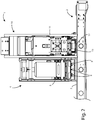
- the first sanding unit 4 of per se known type, comprises a first frame 5 inside of which there is a first operating unit 6 equipped with, in the relative lower part, a base 7 oscillating in translation according to a direction substantially at right angles to the advancing direction A.
- Each plate of said plurality of supporting plates 8 is rotatable about a respective vertical axis passing through the relative centre and is rotatable by means of a motor.
- each plate of the plurality of supporting plates 8 are fitted, underneath, four sander members 9, which are also circular, positioned at an equal angular distance from each other and, in turn, rotatable about the relative axes with respect to the relative plate 8.
- the sander members 9 each have a substantially flat abrasive bottom, facing the underlying conveyor belt 3 and designed to come into contact with the upper surface of the panels positioned above the conveyor belt 3.
- the sander members 9 are also connected to a motor designed to rotate them, in one direction or in the opposite direction, about the relative vertical axis.
- a second sanding unit 10 Downstream of the first sanding unit 4 there is, in a position adjacent to the latter, a second sanding unit 10, also this of a per se known type (for example, such a second sanding unit 10 is described in international patent application no. PCT/US91/05849 ) which performs the specific function of carrying out a fine sanding, that is to say, less coarse than that performed by the first sanding unit 4, in order to further improve the surface finish of the panels.
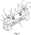
- the second sanding unit 10 is supported by a relative frame 11 and comprises, in the relative lower part, an orbiting support or element 12 with a substantially rectangular shape, positioned transversally to the advancing direction A and coated on the underside with an abrasive element or substance 13, such as, for example, an abrasive paper, facing the conveyor belt 3.
- an abrasive element or substance 13 such as, for example, an abrasive paper
- first movement system 14 For the movement of the orbiting support or element 12 on a plane parallel to the conveyor belt 3 there is a first movement system 14 and a second movement system 15.
- the first movement system 14 includes a first pair of lateral operating units 16a, 16b which comprise, in turn, respective eccentric members 17a, 17b connected to the orbiting support or element 12 and which can be rotated by an electric motor.
- the second movement system 15 comprises, on the other hand, in the space between the of the operating units of the above-mentioned first pair of operating units 16a, 16b, a second pair of operating units 18a, 18b also equipped with respective eccentric members 19a, 19b connected to the orbiting support or member 12 and to a second electric motor designed to rotate them about the respective axes.
- the rotary movements of the operating units of the second pair of operating units 18a, 18b follow circular trajectories which are narrower than those described by the operating units of the first pair of operating units 16a, 16b, in such a way that the orbiting support or element 12 carries out, in fact, a complex movement, according to an orbital trajectory, resulting from the combination of two rotations, that is, a first rotation, which is fast and with a short radius, caused by the second movement system 15 and a second rotation, which is slower and with a larger radius, determined by the action of the first movement system 14.
- the faster and narrower movement allows the transversal scoring to be eliminated from the panels, as it produces a sanding free of any preferential abrasion direction; on the other hand, the second rotation, which is slower and wider, renders the abrasion homogeneous over the entire sanding area.
- the orbiting support or element 12 of the second sanding unit 10 is therefore able to reproduce on the workpiece to be sanded the same movement which would be performed by a manual orbiting platen actuated by a skilled operator.
- the panels transported by the conveyor belt 3 according to an advancing direction A pass, initially, beneath the first sanding unit 4 where they undergo a first sanding operation by the sanding members 9, which contribute to conferring to the upper surface of the panels a first degree of finish thanks to the multi-directional action generated by the rotation of the sander members 9, by the rotation of the supporting plates 8 and by the translational oscillating movement of the base 7 on which the latter are mounted.
- the panels After undergoing the sanding action of the first sanding unit 4, the panels are transported, by the conveyor belt 3, beneath the second sanding unit 10 where they undergo a further sanding which is even finer.
- the orbiting support or element 12 which is already at the same level of the upper surface of the panel or which lowers until reaching it, starts the second sanding operation, during which the surface is finely sanded thanks to the above-mentioned complex movement of the orbiting support or element 12 and of the underlying abrasive element or substance 13.
Abstract
Described is a sander machine (1) for sanding workpieces or elements made of wood or other materials, configured for being mounted in a supplying line (2) for supplying elements or workpieces according to an advancing direction(A). The sander machine (1) comprises: at least a frame (5, 11) and a first sanding unit (4) comprising a base (7) configured for oscillating in translation along a predetermined direction, at least one support (8) connected to said base (7) in such a way as to be rotatable, in use, about a first axis substantially vertical, a least one sander member (9) for sanding, in use, at least one surface of an element or workpiece transported by said supplying line (2), said at least one sander member (9) being mounted on said at least one support (8) so as to be rotatable, in use, about a second axis substantially parallel to said first axis, and first motor means for actuating said base (7), said at least one support (8) and said at least one sander member (9). The sander machine (1) also comprises a second sanding unit (10) comprising: an abrasive element (12, 13) for abrading, in use, at least one surface of an element or workpiece transported by said supplying line (2), a first movement system (14) equipped with at least one first eccentric member (17a, 17b) rotatable, in use, about an axis substantially vertical and connected to said abrasive element (12, 13) in such a way that the rotation of said at least one first eccentric member (17a, 17b) causes a movement of said abrasive element (12, 13) according to an orbital trajectory on a predetermined plane, and second motor means for actuating said at least one eccentric member (17a, 17b).
Description
- This invention relates to an improved sander machine, preferably for sanding panels made of wood, composite materials, metals, Corian, stone or glass.
- More in detail, the invention relates to a sander machine for the surface treatment of workpieces, for hiding as much as possible the signs and deformities present on the external surfaces of the workpieces, in order to render them as uniform as possible.
- More specifically, the machine according to the invention is particularly effective when processing wooden items formed by several slats coupled together in directions incident with each other.
- In fact, in these cases, the machine is able to effectively "mask" the discontinuities of the rough item, due basically to the various directions of the grains of the wood, giving the article a more homogeneous appearance.
- The description below relates to sander machine for sanding wooden panels, but it is quite apparent how the same should not be considered limited to this specific use, as it may also be used, as mentioned above, for sanding workpieces of different shape and type.
- Machines are known for sanding surfaces of workpieces which, however, in many cases are not able to fully perform the function for which they are designed.
- In fact, if the machines of known type are used for sanding workpieces with particularly pronounced surface marks, they are not normally able to effectively hide the marks, leaving the latter clearly visible even to the naked eye.
- In light of the above, the aim of the invention is therefore to provide an improved sander machine which is able to effectively render uniform the external surfaces of the workpieces.
- Another aim of the invention is to provide a sander machine which has fast execution times for the planned sanding.
- Therefore, this invention specifically relates to a sander machine for sanding workpieces or elements made of wood or other materials, configured for being mounted in a supplying line for supplying elements or workpieces according to an advancing direction, said sander machine comprising: at least a frame, a first sanding unit comprising a base configured for oscillating in translation along a predetermined direction, at least one support connected to said base in such a way as to be rotatable, in use, about a first axis substantially vertical, a least one sander member for sanding, in use, at least one surface of an element or workpiece transported by said supplying line, said sander member being mounted on said at least one support so as to be rotatable, in use, about a second axis substantially parallel to said first axis, and first motor means for actuating said base, said at least one support and said at least one sander member; and a second sanding unit comprising an abrasive element for abrading, in use, at least one surface of an element or workpiece transported by said supplying line, a first movement system equipped with at least one first eccentric member rotatable, in use, about an axis substantially vertical and connected to said abrasive element in such a way that the rotation of said at least one first eccentric member causes a movement of said abrasive element according to an orbital trajectory on a predetermined plane, and second motor means for actuating said at least one eccentric member.
- Preferably, according to the invention, said predetermined direction is substantially at right angles to said advancing direction.
- Further, according to the invention, said at least one support and said at least one sander member can rotate, in use, in the same or opposite directions.
- Preferably, according to the invention, said first sanding unit comprises four sander members positioned substantially equidistant from each other.
- Advantageously, according to the invention, said second sanding unit can comprise a second movement system equipped with at least one second eccentric member connected to said abrasive element and rotatable, in use, about a substantially vertical axis according to a circular trajectory narrower than a circular trajectory of rotation of said at least one first eccentric member.
- Moreover, according to the invention, said abrasive element can comprise a substantially flat abrasive surface.
- Advantageously, according to this invention, said second sanding unit can be positioned, in use, downstream of said first sanding unit with respect to said advancing direction.
- Further, according to this invention, said first sanding and said second sanding unit can be positioned mutually adjacent with respect to said advancing direction.
- The invention is now described, by way of example and without limiting the scope of the invention, with reference to the accompanying drawings which illustrate preferred embodiments of it, in which:
-
Figure 1 is a partial perspective view of the sander machine according to the invention; -
Figure 2 is a partial side view of the machine shown inFigure 1 ; -
Figure 3 shows, partially, a first operating unit of which the machine shown inFigures 1 and2 is composed; and -
Figure 4 shows, schematically, the general operating principle of a second operating unit of the machine illustrated inFigures 1 and2 . - In the various figures similar parts are labelled with the same reference numerals.
- With reference to the accompanying drawings, the numeral 1 denotes in its entirety a sander machine according to the invention.
- The sander machine 1 comprises, in particular, a supplying
line 2, in turn comprising aconveyor belt 3, for transporting the panels to be sanded along an advancing direction A. - The sander machine 1 also includes a
first sanding unit 4 for carrying out on the panels a first coarser sanding operation. - The
first sanding unit 4, of per se known type, comprises afirst frame 5 inside of which there is afirst operating unit 6 equipped with, in the relative lower part, a base 7 oscillating in translation according to a direction substantially at right angles to the advancing direction A. - On the lower side of the base 7 is fitted, in a rotatable fashion, a plurality of
circular supporting plates 8, aligned with each other transversally to the advancing direction A. - Each plate of said plurality of supporting
plates 8 is rotatable about a respective vertical axis passing through the relative centre and is rotatable by means of a motor. - Moreover, on each plate of the plurality of supporting
plates 8 are fitted, underneath, foursander members 9, which are also circular, positioned at an equal angular distance from each other and, in turn, rotatable about the relative axes with respect to therelative plate 8. - The
sander members 9 each have a substantially flat abrasive bottom, facing theunderlying conveyor belt 3 and designed to come into contact with the upper surface of the panels positioned above theconveyor belt 3. - The
sander members 9 are also connected to a motor designed to rotate them, in one direction or in the opposite direction, about the relative vertical axis. - Downstream of the
first sanding unit 4 there is, in a position adjacent to the latter, asecond sanding unit 10, also this of a per se known type (for example, such asecond sanding unit 10 is described in international patent application no.PCT/US91/05849 first sanding unit 4, in order to further improve the surface finish of the panels. - The
second sanding unit 10 is supported by arelative frame 11 and comprises, in the relative lower part, an orbiting support orelement 12 with a substantially rectangular shape, positioned transversally to the advancing direction A and coated on the underside with an abrasive element orsubstance 13, such as, for example, an abrasive paper, facing theconveyor belt 3. - For the movement of the orbiting support or
element 12 on a plane parallel to theconveyor belt 3 there is afirst movement system 14 and asecond movement system 15. - The
first movement system 14 includes a first pair oflateral operating units eccentric members element 12 and which can be rotated by an electric motor. - The
second movement system 15 comprises, on the other hand, in the space between the of the operating units of the above-mentioned first pair ofoperating units operating units eccentric members member 12 and to a second electric motor designed to rotate them about the respective axes. - Specifically, the rotary movements of the operating units of the second pair of
operating units operating units element 12 carries out, in fact, a complex movement, according to an orbital trajectory, resulting from the combination of two rotations, that is, a first rotation, which is fast and with a short radius, caused by thesecond movement system 15 and a second rotation, which is slower and with a larger radius, determined by the action of thefirst movement system 14. - More specifically, the faster and narrower movement allows the transversal scoring to be eliminated from the panels, as it produces a sanding free of any preferential abrasion direction; on the other hand, the second rotation, which is slower and wider, renders the abrasion homogeneous over the entire sanding area.
- The orbiting support or
element 12 of thesecond sanding unit 10 is therefore able to reproduce on the workpiece to be sanded the same movement which would be performed by a manual orbiting platen actuated by a skilled operator. - During the operation of the sander machine 1, the panels transported by the
conveyor belt 3 according to an advancing direction A pass, initially, beneath thefirst sanding unit 4 where they undergo a first sanding operation by thesanding members 9, which contribute to conferring to the upper surface of the panels a first degree of finish thanks to the multi-directional action generated by the rotation of thesander members 9, by the rotation of the supportingplates 8 and by the translational oscillating movement of the base 7 on which the latter are mounted. - After undergoing the sanding action of the
first sanding unit 4, the panels are transported, by theconveyor belt 3, beneath thesecond sanding unit 10 where they undergo a further sanding which is even finer. - In fact, once a predetermine panel has reached the position beneath the
second sanding unit 10, the orbiting support orelement 12, which is already at the same level of the upper surface of the panel or which lowers until reaching it, starts the second sanding operation, during which the surface is finely sanded thanks to the above-mentioned complex movement of the orbiting support orelement 12 and of the underlying abrasive element orsubstance 13. - Surprisingly, it has been found that the combination of the two sanding operations performed by the first 4 and by the second 10 sanding units produces considerable effects on the workpieces sanded in terms of uniformity and quality of the surface finish obtained.
- This invention is described by way of example only, without limiting the scope of application, according to its preferred embodiments, but it shall be understood that the invention may be modified and/or adapted by experts in the field without thereby departing from the scope of the inventive concept, as defined in the claims herein.
Claims (8)
- Sander machine (1) for sanding workpieces or elements made of wood or other materials, which is configured to be mounted in a supplying line (2) for supplying elements or workpieces according to an advancing direction (A), said sander machine (1) comprising:at least one frame (5, 11),a first sanding unit (4) comprising:a base (7) which is configured to oscillate in translation along a predetermined direction,at least one support (8) which is connected with said base (7) such as to be rotatable, when in use, about a first axis which is substantially vertical,at least one sander member (9) for sanding, when in use, at least one surface of a element or a workpiece being transported by said supplying line (2), said at least one sander member (9) being mounted on said at least one support (8) such as to be rotatable, when in use, about a second axis which is substantially parallel to said first axis, efirst motor means for activating said base (7), said at least one support (8) and said at least one sander member (9); anda second sanding unit (10) comprising:an abrasive element (12, 13) for abrading, when in use, at least one surface of a element or a workpiece being transported by said supplying line (2),a first movement system (14) which is provided with at least one eccentric member (17a, 17b) which is rotatable, when in use, about a substantially vertical axis and connected with said abrasive element (12, 13) such that the rotation of said at least one eccentric member (17a, 17b) causes said abrasive element (12, 13) to move according to an orbital trajectory on a predetermined plane, andsecond motor means for activating said at least one eccentric member (17a, 17b).
- Sander machine (1) according to claim 1, characterized in that said predetermined direction is substantially orthogonal with respect to said advancing direction (A).
- Sander machine (1) according to claim 1 or 2, characterized in that said at least one support (8) and said at least one sander member (9) rotate, when in use, in the same sense or in senses being opposite to each other.
- Sander machine (1) according to any one of the preceding claims, characterized in that said first sanding unit (4) comprises four sander members (9) which are placed substantially equidistant to one another.
- Sander machine (1) according to any one of the preceding claims, characterized in that said second sanding unit (10) comprises a second movement system (15) which is provided with at least one second eccentric member (19a, 19b) which is connected with said abrasive element (12, 13) and rotatable, when in use, about a substantially vertical axis according to a circular trajectory which is narrower than a circular trajectory for the rotation of said at least one first eccentric member (17a, 17b).
- Sander machine (1) according to any one of the preceding claims, characterized in that said abrasive element comprises an abrasive surface (13) which is substantially flat.
- Sander machine (1) according to any one of the preceding claims, characterized in that said second sanding unit (10) is placed, when in use, downstream from said first sanding unit (4) with respect to said advancing direction (A).
- Sander machine (1) according to any one of the preceding claims, characterized in that said first sanding unit (4) and said second sanding unit (10) are placed adjacent to each other with respect to said advancing direction (A).
Applications Claiming Priority (1)
| Application Number | Priority Date | Filing Date | Title |
|---|---|---|---|
| IT102017000054727A IT201700054727A1 (en) | 2017-05-19 | 2017-05-19 | Improved sanding machine. |
Publications (1)
| Publication Number | Publication Date |
|---|---|
| EP3409418A1 true EP3409418A1 (en) | 2018-12-05 |
Family
ID=60020419
Family Applications (1)
| Application Number | Title | Priority Date | Filing Date |
|---|---|---|---|
| EP18170971.8A Withdrawn EP3409418A1 (en) | 2017-05-19 | 2018-05-07 | Sander machine |
Country Status (4)
| Country | Link |
|---|---|
| EP (1) | EP3409418A1 (en) |
| AT (1) | AT16659U1 (en) |
| DE (1) | DE202018006070U1 (en) |
| IT (1) | IT201700054727A1 (en) |
Cited By (1)
| Publication number | Priority date | Publication date | Assignee | Title |
|---|---|---|---|---|
| CN109500678A (en) * | 2018-12-28 | 2019-03-22 | 北京惠点信元科技有限公司 | Timber sander |
Citations (2)
| Publication number | Priority date | Publication date | Assignee | Title |
|---|---|---|---|---|
| US5081794A (en) * | 1990-08-17 | 1992-01-21 | Haney Donald E | Sander with orbiting platen and abrasive |
| EP2377646A1 (en) * | 2010-04-19 | 2011-10-19 | SCM Group S.p.A. | Device for finishing edges and/or outer surfaces of workpieces |
Family Cites Families (1)
| Publication number | Priority date | Publication date | Assignee | Title |
|---|---|---|---|---|
| KR101274718B1 (en) | 2010-01-28 | 2013-06-12 | 엘지디스플레이 주식회사 | Deposition Mask Unit and Mask Assembly comprising the same |
-
2017
- 2017-05-19 IT IT102017000054727A patent/IT201700054727A1/en unknown
-
2018
- 2018-05-07 DE DE202018006070.4U patent/DE202018006070U1/en active Active
- 2018-05-07 EP EP18170971.8A patent/EP3409418A1/en not_active Withdrawn
- 2018-05-07 AT ATGM11/2019U patent/AT16659U1/en unknown
Patent Citations (2)
| Publication number | Priority date | Publication date | Assignee | Title |
|---|---|---|---|---|
| US5081794A (en) * | 1990-08-17 | 1992-01-21 | Haney Donald E | Sander with orbiting platen and abrasive |
| EP2377646A1 (en) * | 2010-04-19 | 2011-10-19 | SCM Group S.p.A. | Device for finishing edges and/or outer surfaces of workpieces |
Cited By (2)
| Publication number | Priority date | Publication date | Assignee | Title |
|---|---|---|---|---|
| CN109500678A (en) * | 2018-12-28 | 2019-03-22 | 北京惠点信元科技有限公司 | Timber sander |
| CN109500678B (en) * | 2018-12-28 | 2023-09-01 | 北京惠点信元科技有限公司 | Board sander |
Also Published As
| Publication number | Publication date |
|---|---|
| AT16659U1 (en) | 2020-04-15 |
| DE202018006070U1 (en) | 2019-02-14 |
| IT201700054727A1 (en) | 2018-11-19 |
Similar Documents
| Publication | Publication Date | Title |
|---|---|---|
| KR101748458B1 (en) | Machine for smoothing or polishing slabs of stone material, such as natural and agglomerated stone, ceramic and glass | |
| KR100829043B1 (en) | A apparatus for grinding the surface of workpiece | |
| NO327527B1 (en) | Crushing device for surface treatment | |
| EP1053827B1 (en) | Belt sander with orbitally translated abrasive belt | |
| US20130237135A1 (en) | Disc sander for deburring and/or rounding of metal work pieces | |
| US6299512B1 (en) | Belt sander with orbitally translated abrasive belt | |
| KR101333296B1 (en) | Apparatus for grinding a surface of a tile | |
| WO2017134616A1 (en) | Orbital polishing machine for polishing stone slabs | |
| EP3409418A1 (en) | Sander machine | |
| KR101382494B1 (en) | Automatic buffing machine | |
| JPH0197553A (en) | Method of automatically smoothing and grinding marble board, granite board, slate, etc. | |
| KR101511593B1 (en) | Glass For Cellular Phone, Grinding Wheel And Apparatus For Grinding That Glass | |
| WO2009071093A1 (en) | Grinding apparatus and apparatus for grinding a surface on plate-shaped items | |
| EP3934846A1 (en) | Multi-tool machine for surface processing of slabs of stone material or the like | |
| US2772522A (en) | Mechanical sanders | |
| US1246958A (en) | Sanding-machine. | |
| CA2348681C (en) | Belt sander with orbitally translated abrasive belt | |
| US1475741A (en) | Corner-rounding machine | |
| KR102656838B1 (en) | Apparatus for Automatic Sanding | |
| JP2004082241A (en) | Work supporting tool in chamfering grinding device | |
| JP2006181697A (en) | Surface polishing device and method | |
| KR102006334B1 (en) | Brush type abrasive article and apparatus | |
| EP3411182B1 (en) | Orbital polishing machine for polishing stone slabs | |
| JPH02237752A (en) | Beveling device for glass body | |
| JPS59129650A (en) | Apparatus for automatically polishing sheet glass |
Legal Events
| Date | Code | Title | Description |
|---|---|---|---|
| PUAI | Public reference made under article 153(3) epc to a published international application that has entered the european phase |
Free format text: ORIGINAL CODE: 0009012 |
|
| AK | Designated contracting states |
Kind code of ref document: A1 Designated state(s): AL AT BE BG CH CY CZ DE DK EE ES FI FR GB GR HR HU IE IS IT LI LT LU LV MC MK MT NL NO PL PT RO RS SE SI SK SM TR |
|
| AX | Request for extension of the european patent |
Extension state: BA ME |
|
| STAA | Information on the status of an ep patent application or granted ep patent |
Free format text: STATUS: THE APPLICATION IS DEEMED TO BE WITHDRAWN |
|
| 18D | Application deemed to be withdrawn |
Effective date: 20190606 |