EP3408937B1 - Verfahren und system zur bereitstellung von informationen über ein zielobjekt in einem formatierten ausgangssignal - Google Patents
Verfahren und system zur bereitstellung von informationen über ein zielobjekt in einem formatierten ausgangssignal Download PDFInfo
- Publication number
- EP3408937B1 EP3408937B1 EP17702179.7A EP17702179A EP3408937B1 EP 3408937 B1 EP3408937 B1 EP 3408937B1 EP 17702179 A EP17702179 A EP 17702179A EP 3408937 B1 EP3408937 B1 EP 3408937B1
- Authority
- EP
- European Patent Office
- Prior art keywords
- pulses
- sensor
- pulse
- pulse train
- output signal
- Prior art date
- Legal status (The legal status is an assumption and is not a legal conclusion. Google has not performed a legal analysis and makes no representation as to the accuracy of the status listed.)
- Active
Links
Images


Classifications
-
- G—PHYSICS
- G01—MEASURING; TESTING
- G01R—MEASURING ELECTRIC VARIABLES; MEASURING MAGNETIC VARIABLES
- G01R33/00—Arrangements or instruments for measuring magnetic variables
- G01R33/02—Measuring direction or magnitude of magnetic fields or magnetic flux
- G01R33/06—Measuring direction or magnitude of magnetic fields or magnetic flux using galvano-magnetic devices
- G01R33/07—Hall effect devices
-
- H—ELECTRICITY
- H03—ELECTRONIC CIRCUITRY
- H03K—PULSE TECHNIQUE
- H03K5/00—Manipulating of pulses not covered by one of the other main groups of this subclass
- H03K5/01—Shaping pulses
- H03K5/08—Shaping pulses by limiting; by thresholding; by slicing, i.e. combined limiting and thresholding
-
- H—ELECTRICITY
- H03—ELECTRONIC CIRCUITRY
- H03K—PULSE TECHNIQUE
- H03K7/00—Modulating pulses with a continuously-variable modulating signal
- H03K7/08—Duration or width modulation ; Duty cycle modulation
-
- G—PHYSICS
- G08—SIGNALLING
- G08B—SIGNALLING SYSTEMS, e.g. PERSONAL CALLING SYSTEMS; ORDER TELEGRAPHS; ALARM SYSTEMS
- G08B25/00—Alarm systems in which the location of the alarm condition is signalled to a central station, e.g. fire or police telegraphic systems
- G08B25/01—Alarm systems in which the location of the alarm condition is signalled to a central station, e.g. fire or police telegraphic systems characterised by the transmission medium
- G08B25/04—Alarm systems in which the location of the alarm condition is signalled to a central station, e.g. fire or police telegraphic systems characterised by the transmission medium using a single signalling line, e.g. in a closed loop
- G08B25/045—Alarm systems in which the location of the alarm condition is signalled to a central station, e.g. fire or police telegraphic systems characterised by the transmission medium using a single signalling line, e.g. in a closed loop with sensing devices and central station in a closed loop, e.g. McCullough loop
Definitions
- Subject matter disclosed herein relates generally to sensors and, more particularly, to techniques, circuits, and systems for providing information regarding a sensor, a target object and/or an environment in which a sensor is disposed.
- sensors can be used in various types of devices to measure and monitor properties of systems in a wide variety of different applications.
- sensors have become common in products that rely on electronics in their operation, such as automobile control systems.
- Common examples of automotive applications are the detection of ignition timing from an engine crankshaft and/or camshaft, and the detection of wheel speed for anti-lock braking systems and four-wheel steering systems.
- sensors can use serial communication to send data in the form of a stream of pulses or bits over a communication channel or to a computer or other processing system.
- each pulse stream conveys a limited amount of data.
- US 2014/0358320 A1 provides a measurement system including a speed plus sensor and a control unit.
- the speed plus sensor is configured to detect a magnetic field in response to speed and resonance characteristics.
- the speed plus sensor is also configured to generate a sensor output signal having speed data and enhanced resonance data.
- the control unit is configured to receive the sensor output signal.
- US 2015/0268263 A1 provides a speed sensor device including a sensor element to provide a sensor signal, a status module to provide status information of the speed sensor device; and a processing module to generate an output signal.
- the output signal is derived from the sensor signal, if the status information is indicative of a non-critical state of the speed sensor device, and the output signal is a safety message signal having signal edges such that time intervals between subsequent congeneric signal edges are equal to or shorter than a preselected threshold, if the status in-formation is indicative of a critical state of the speed sensor device.
- An Electronic Control Unit includes an interface for receiving a signal having signal edges from a speed sensor device and a processing unit to analyze time intervals between subsequent congeneric signal edges.
- CN 204 989 435 U provides a triangular pyramid three-dimensional pulsed magnetic field measuring device, which can be applied to measurement of transient electromagnetic pulsed magnetic fields.
- the present disclosure is directed toward concepts, methods and systems for providing a signal pulse stream which conveys information about a target object (or more simply a "target") and/or a sensor in a formatted output signal.
- a signal pulse stream provided in accordance with the concepts, methods and systems described herein is capable of conveying a range of information which larger than that which may be conveyed using prior art techniques.
- the formatted output signal uses a pulse width protocol to code information by varying widths of pulses in an output signal pulse train.
- a pulse width protocol may code information by varying widths of pulses and/or amplitudes in an output signal pulse train.
- the systems described herein may include one or more of the following features independently or in combination with another feature.
- the present invention provides a method as claimed in claim 1.
- a coding protocol is provided through which a sensor's state or serial digital data is conveyed by changing widths of pulses in a stream of pulses (also referred to herein as a "pulse train").
- Each pulse can have multiple edge-to-edge widths which may represent a device state and/or a data bit in a data word.
- Such information can be coded for applications in different modes, including, but not limited to, a testing mode as well as a mission mode.
- the pulses included in a pulse train are provided having different amplitudes, (i.e., high and low pulses).
- each output signal pulse train portion includes at least one pulse having a low amplitude and at least one pulse having a high amplitude.
- the method further includes measuring widths of the two or more pulses in the output signal pulse train portion in response to at least one of the two or more pulses reaching a first amplitude threshold. A logic value is determined for each of the measured widths. The logic values may be used to determine a data word.
- the output signal pulse train portion includes N pulses and the data word is a base N data word. In one embodiment, the output signal pulse train portion includes 3 pulses and the data word is a base 3 data word.
- the device state may correspond to a state of the target or a state of a sensor monitoring the target.
- the output signal pulse train portion may include three pulses with a first pulse having a first width corresponding to a first logic value, a second pulse having a second width corresponding to a second logic value, and a third pulse having a third width corresponding to a third logic value. It should, of course, be appreciated that in other embodiments, fewer or greater than three pulse widths and three logic values may be used.
- the output signal pulse train portion may be used to determine airgap properties between the target and a sensor monitoring the target based on the measured widths of the two or more pulses.
- the method includes, in response to detecting the feature, detecting a second feature after a predetermined time threshold and generating a time out function responsive to exceeding the predetermined time threshold.
- the time function may instruct a receiver to ignore the first feature and wait for a third feature detection.
- the method includes generating a first pulse in the output signal pulse train portion is responsive to the detected first feature.
- the first feature may be a first or leading edge of the target and the first pulse with predetermined characteristics to identify the leading edge.
- the first pulse may be identified based on the first pulse having an amplitude greater than or equal to an amplitude threshold.
- the present invention provides a system as claimed in claim 11.
- the system may further include a receiver coupled to the sensor to receive the output signal pulse train via a signal path.
- the senor comprises a magnetic field sensor.
- the magnetic field sensor may comprise a single-chip Hall effect sensor integrated circuit.
- the magnetic field sensor comprises one or more Hall effect elements.
- the magnetic field sensor comprises three Hall effect elements. Each of the Hall effect elements may be positioned along edges or at vertices of an equilateral triangle within the sensor. The three Hall effect elements can be configured to detect a magnetic profile of the target object simultaneously but at different locations within the sensor.
- the sensor comprises one or more detection circuits coupled to the magnetic field sensor.
- the one or more detection circuits may be configured to detect at least one of (a) a parameter of an environment in which the sensor is disposed, (b) the first feature of the target object, and (c) a parameter of a relationship between the sensor and the target object.
- the one or more detection circuits are configured to a direction of the target object relative to the sensor. In other embodiments, the one or more detection circuits are configured to detect airgap properties between the target object and the sensor.
- the senor is configured to generate a first pulse in the output signal pulse train portion responsive to the detected first feature.
- the first feature may be a leading edge of the target and the first pulse with predetermined characteristics to identify the leading edge.
- the receiver can be configured to identify the first pulse based on the first pulse having an amplitude greater than or equal to an amplitude threshold.
- the present disclosure describes a method of providing information.
- the method comprises detecting a change in a condition experienced by the sensor (e.g., a change in a characteristic of an environmental in which the sensor is disposed) and generating a plurality of pulses in response to the detected change, with a first one of the plurality of pulses having a first amplitude and second ones of the plurality of pulses having an amplitude different from the first amplitude with each of the second ones of the plurality of pulses having one of a plurality of pulse characteristic values which represent one of a like plurality of different logic values.
- the plurality of pulse characteristic values correspond to one of a plurality of different pulse width values.
- the second ones of the plurality of pulses may have the same amplitude.
- at least some of the pulse width values are multiples of each other.
- the method further comprises forming a data word using at least two pulses wherein the data word conveys a characteristic of at least one of: (a) a target; and (b) an environment in which the target is disposed.
- a first one of the first pulse width values may be approximately twice as long as a second one of the pulse width values.
- a first one of the logic values may correspond to a logic zero value and a second one of the logic values may correspond to a logic one value.
- the first and second pulse characteristics correspond to one of: a. a pulse width characteristic; b. a pulse current level characteristic; and c. a pulse voltage level characteristic.
- the data word may convey a direction of rotation of a target.
- the senor corresponds to at least one of a pressure sensor, temperature sensor, bolometer or infrared sensor. In other examples, the sensor corresponds to an accelerometer, gyroscope or gas sensor.
- the detected change is a change in a magnetic field.
- the detected condition or characteristic includes at least one of: a change in temperature, a change in pressure, a change in a gas level, a change in a radiation level or a change in a change in speed.
- the system includes a resistive element coupled between the second input of a first comparison device and a second input of a second comparison device.
- the present disclosure is generally directed toward a sensor capable of providing information about a target and/or the sensor itself using a formatted output signal pulse train as well as towards related methods and systems.
- the signal pulse train includes multiple pulses each of which may have one or more different characteristics including, but not limited to, different amplitudes and pulse widths.
- the different characteristics (e.g., positon, amplitude, width) of each of the pulses may be used to provide a variety of information related to the target and/or the sensor itself.
- the output signal pulse train includes pulses In which the pulse widths may represent either device state information or data bits used to form data words. In some cases, widths and/or amplitudes of consecutive pulses within a pulse train are used to provide state information or to form data words. Thus, a single device or application may use the pulse train information for either device state or data words within different modes. For example, during a first operating mode a device or application may use device state information. In a second operating mode (e.g. a test mode), however, the device or application may use data words.
- the first operating mode may refer to operation of a device during its intended (or normal) operation or "mission” (and thus is sometimes referred to "mission mode").
- Test mode may refer to a time period during which various components of a device are tested.
- the pulse train includes delimiting pulses such that a series of pulses between the delimiting pulses may be considered together to convey information (e.g. device state information or data bits used to form data words).
- a delimiting pulse followed by a series of pulses occurring before a next delimiting pulse may be considered together to convey information (i.e. the first delimiting pulse and the following series of pulses are considered together to convey information).
- the delimiting pulses define portions of a pulse train.
- the pulse train may be considered as having a plurality of pulse train portions comprised of a first (or delimiting) pulse followed by one or more second (or non-delimiting) pulses.
- the first pulse in each pulse train portion is generated in response to detection by the sensor of some feature of a target.
- a sensor may provide a first (or delimiter) pulse in response to detection of each edge of a plurality of teeth on an exciter wheel.
- the sensor may generate pulses in response to either a rising edge, falling edge, or, in the case of double data rate, both rising and failing edges of the exciter wheel target or in response to a magnetic differential signal.
- delimiting pulses may be distinguished from non-delimiting pulses by some pulse characteristic (e.g. a pulse amplitude or a pulse width characteristic).
- some pulse characteristic e.g. a pulse amplitude or a pulse width characteristic.
- delimiting pulses may be provided having an amplitude which differs from the amplitude of non-delimiting pulses.
- the pulse train represents a device state or a data word having a base number based upon a potential number of pulse widths (e.g., a base three (3) system would have three (3) potential pulse widths and more generally a base N system would have N potential widths).
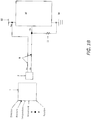
- a sensor 2 is disposed proximate a target object 4 (or more simply, a "target").
- Sensor 2 may be provided, for example, as a magnetic field sensor.
- sensor 2 may generate a series of pulses, referred to herein as a pulse train, the characteristics and benefits of which will be described herein below.
- Sensor 2 may be the same as or similar to the types described in each of U.S. Patent No. 6,815,944, filed on October 29, 2002 , U.S. Patent No. 7,026,808, filed on September 23, 2004 , U.S. Patent No. 8,624,588, filed on July 31, 2008 , U.S. Patent No. 9,151,771, filed on December 2, 2013 , U.S. Patent No. 8,994,369, filed on December 2, 2013 , and U.S. Patent No. 8,754,640, filed on June 18, 2012 .
- Signal paths 8a, 8b couple sensor 2 to a receiver 10.
- signal paths 8a, 8b couple a supply voltage 12 and a reference point (i.e., ground) 14 to sensor 2 as will be discussed in greater detail below.
- signal path 8 is shown provided as a two wire line 8a, 8b although any signal path or transmission line suitable for transmission of a pulse train from sensor 2 to receiver 10 may be used.
- the output signal pulse train generated by sensor 2 is appropriate for use in two-wire, three-wire or n+1 wire sensor solutions.
- Sensor 2 is disposed within a predetermined distance from target 4 to detect characteristics and features of target 4, such as speed and direction information.
- the particular positioning of sensor 2 with respect to target 4 will, of course, depend upon the needs of the particular application or system in which the sensor 2 is being used.
- sensor 2 may be adapted (and in some cases, optimized) for use In a wide variety of different applications including, but not limited to, accelerometer applications, gyroscope applications, gas sensor applications, pressure sensor applications, temperature sensor applications, bolometer sensor applications, infrared sensor applications and automotive applications.
- sensor 2 may sense different properties and characteristics of the environment 7 around sensor 2.
- sensor 2 is configured to detect a direction value, pressure value, temperature value, acceleration value, movement value, rotation value, etc.
- sensor 2 is configured to detect a magnetic field variation in environment 7.
- the magnetic field variation may be used to detect a wide variety of different properties and characteristics of the environment 7 around sensor 2.
- the magnetic field variation may be used to detect a direction value, rotation value, angle value, speed value, etc.
- sensor 2 can be positioned at varying distances and oriented at various angles relative to target 4 based upon the needs of a particular application.
- sensor 2 can be mounted at any angle in a plane perpendicular to a rotation of target 4.
- Sensor 2 may be positioned such that a plane of least one surface of sensor 2 is parallel with a surface or edge of target 4.
- Sensor 2 is configured to generate an output signal pulse train in response to detecting characteristics and mechanical features (or more simply "features") of target 4.
- sensor 2 may be a magnetic field sensor integrated circuit (IC).
- sensor 2 may be a single-chip Hall-effect sensor IC.
- the Hall-effect sensor may have one or more Hall elements 3.
- the Hall elements 3 may be positioned along edges or at vertices of an equilateral triangle within sensor 2.
- each of the Hall elements 3 sense the magnetic profile of target 4 simultaneously but at different locations.
- sensor 2 includes one or more detection circuits 5 coupled to Hall effect elements 3.
- the one or more detection circuits 5 can be configured to detect at least one of (a) a parameter of an environment in which the sensor is disposed, (b) the first feature of the target object, and (c) a parameter of a relationship between the sensor and the target object.
- the one or more detection circuits 5 can be configured to detect a direction of the target object 4 relative to sensor 2 and airgap properties between target object 4 and sensor 2.
- the one or more detection circuits can be configured to detect a magnetic field variation in the environment in which sensor 2 is disposed.
- Sensor 2 may be used to communicate information for a variety of different sensors.
- sensor 2 may be adapted for used in an accelerometer, a gyrometer, a gas sensor, a pressure sensor, or a temperature sensor.
- Sensor 2 may detect a condition of an environment in which the sensor is disposed (e.g. a condition experienced by sensor 2) and generate the output signal pulse train to provide information corresponding to this condition.
- the detected condition is a change In a magnetic field.
- the detected condition Includes at least one of: a change in temperature, a change in pressure, a change in a gas level, a change in a radiation level or a change in a change in speed.
- the output signal pulse train may be initiated by a change In the condition that falls below or above a predetermined threshold or outside a predetermined acceptable range of values. For example, a temperature experienced by sensor 2 may fall below or above a predetermined threshold or a pressure experienced by sensor 2 may fall below or above a predetermined threshold.
- sensor 2 may generate the output signal pulse train to indicate this change in condition.
- sensor 2 may generate the output signal pulse train as part of a built-in test (BIT) or in response to a test probe applied to a particular device.
- BIT built-in test
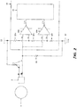
- signal paths 8a, 8b couple sensor 2 to receiver 10, supply voltage 12 and reference point (i.e., ground) 14.
- a first signal path 8a is coupled to supply voltage 12 and receiver 10 and a second signal path 8b Is coupled to receiver 10and to reference point 14 through a resistor 22.
- the output signal pulse train generated by sensor 2 propagates to receiver 10 via one or both of signal paths 8a, 8b.
- the output signal pulse train propagates to receiver 10 via signal path 8b while in other embodiments, the output signal pulse train propagates to receiver 10 via signal path 8a.
- Receiver 10 receives the pulse train provided thereto and In response thereto determines device state information and/or data bit values (or word values). In one embodiment, receiver 10 identifies a first (or delimiter) pulse in the pulse train by detecting a particular pulse characteristic (e.g., pulse amplitude or pulse width or some other pulse characteristic) and then begins measuring pulse widths of the following (non-delimiter) pulses. As will be described in detail further below, the widths of both high and low pulses are used to convey information via the pulse train.
- a particular pulse characteristic e.g., pulse amplitude or pulse width or some other pulse characteristic
- an output signal pulse train 9 includes a plurality of pulse train portions, here three (3) pulse train portions, 9a-9c.
- the beginning of each pulse train portion 9a-9c is identified by first (or delimiter) pulses 11a-11c.
- First (or delimiter) pulse In the output signal pulse train may be identified by a pulse characteristic which differs from a like characteristic of every other non-delimiter pulse in the output signal pulse train.
- an amplitude characteristic is used.
- first pulses 11a-11c in the output signal pulse train portions 9a-9c are provided having an amplitude which differs from the amplitude of the remaining non-delimiter pulses (e.g.
- first (or delimiter) pulses are here shown having an amplitude which is greater than an amplitude of all other pulses in the pulse train (or greater than a predetermined amplitude threshold value) In other embodiments, it may be desirable or necessary that first (or delimiter) pulses are provided having an amplitude which is less than an amplitude of all other pulses in the pulse train (or less than an amplitude threshold value).
- a pulse width characteristic (rather than an amplitude characteristic) may be used to identify the first (or delimiter) pulse.
- each first (or delimiter) pulse in the output signal pulse train may be identified by having a pulse width which differs from the pulse width of the non-delimiter pulses in the pulse train.
- the delimiter (or first) pulse may be provided having a pulse width which is either less than or greater than a width of all other non-delimiter pulses in the pulse train or greater or less than a predetermined pulse width threshold value.
- the output signal pulse train may include data associated with detected characteristics and/or features of target 4 or with characteristics and/or features associated with the senor itself.
- the data may be transmitted in different forms, Including as a current signal, a voltage signal value, an RF signal characteristic value (e.g. a current voltage, frequency, or phase characteristic), etc.
- Receiver 10 includes a pair of comparison devices (e.g. comparators) 16a, 16b and a processor 20 (e.g., state machine, digital block, controller, etc.). Comparison devices 16a, 16b have two inputs that are coupled to sensor 2 through signal paths 8. An output 17a, 17b of each comparison device 16a, 16b is coupled to processor 20.
- comparison devices 16a, 16b have two inputs that are coupled to sensor 2 through signal paths 8.
- An output 17a, 17b of each comparison device 16a, 16b is coupled to processor 20.
- first signal path 8a couples supply voltage 12 to a first input of first comparison device 16a and second comparison device 16b. While a pulse width pulse train such as that described in FIG. 1C Is provided to receiver 10 via signal path 8b.
- Supply voltage 12 may provide a reference voltage to first and second comparison devices 16a, 16b.
- resistive elements 18a, 18b, 18c are disposed along the first signal path 8a between supply voltage 12 and a first Input of each of first and second comparison devices 16a, 16b.
- each resistive element 18a, 18b, 18c provides a voltage drop to generate and provide a predetermined reference voltage to first and second comparison devices 16a, 16b.
- a first resistor 18a is disposed between supply voltage 12 and first input of first comparison device 16a.
- a second resistor 18b is disposed between the first Input of first comparison device 16a and the first input of second comparison device 16b.
- a third resistor 18c is disposed between the first input of second comparison device 16b and a reference point 14.
- Resistive elements 18a, 18b, 18c may be sized to various values according to a particular application and the properties of the components in a corresponding sensor system.
- first and second comparison devices 16a, 16b compare the predetermined reference voltage to data output (i.e., an output signal pulse train) generated by sensor 2.
- the data output may be transmitted in different forms, including as a current value, a voltage value or a RF signal.
- second signal path 8b provides data output (e.g., characteristics and features associated with target 4 and/or characteristics and features associated with sensor 2) from sensor 2 to first and second comparison devices 16a, 16b.
- second signal path 8b couples sensor 2 to a second input of each of first and second comparison devices 16a, 16b.
- first signal path 8a provides data output from sensor 2 to first and second comparison devices 16a, 16b and second signal path 8b couples supply voltage 12 to first and second comparison device 16a, 16b.
- second signal path 8b is coupled to ground (i.e., reference point 14) through a load resistor 22.
- Load resistor 22 is disposed between a node of second signal path 8b and reference point 14.
- the node of second signal path 8b is disposed between the output of sensor 2 and the second input of first and second comparison devices 16a, 16b.
- Load resistor 22 may be used to modify or set an output value of sensor 2 that is provided to the second input of first and second comparison devices 16a, 16b to a predetermined level.
- load resistor 22 provides a voltage drop corresponding to a product of an output of sensor 2 and a value of resistor 22.
- Load resistor 22 may be sized to various values according to a particular application and the properties of the components in a corresponding sensor system.
- comparison devices 16a, 16b are arranged to form a window comparator. However, it should be appreciated that comparators may be organized in other arrangements depending upon a particular application.
- First and second comparison devices 16a, 16b compares two inputs (e.g., two voltages, two current, two radio frequency (RF) signals) and output a digital signal. Outputs of first and second comparison devices 16a, 16b are coupled to processor 20.
- Processor 20 can be configured to compare the output 17a of first comparison device 16a to the output 17b of second comparison device 16b.
- Processor 20 may be a logic or state machine and be configured to receive outputs 17a, 17b and determine device state information and/or data bits. For example, processor 20 is configured to determine a logic value for each of the measured widths.
- Processor 20 may be any computing device suitable for the execution of a computer program include, by way of example, both general and special purpose microprocessors, and any one or more processors of any kind of digital computer.
- processor 20 can also include, or be operatively coupled to receive data from or transfer data to, or both, one or more memory systems or mass storage devices for storing data, e.g., magnetic, magneto optical disks, or optical disks.
- Processor 20 and the memory can be supplemented by, or incorporated in, special purpose logic circuitry.
- processor 20 can be configured to measure widths and amplitudes of each pulse in an output signal pulse train.
- Processor 20 may identify a particular pulse in a pulse train portion (e.g., a first pulse, a second pulse, a third pulse, etc.) based upon the pulse having an amplitude greater than or equal to an amplitude threshold.
- the amplitude threshold may be a threshold value, amplitude, level or height used to identify the particular pulse in the output signal pulse train portion.
- the receiver begins measuring the pulses widths in response to a detected first feature of target 4 reaching a first amplitude threshold.
- the first feature may be identified via one or more predetermined characteristics of a target (e.g., a leading edge of a tooth or an exciter wheel).
- Processor 20 Is configured to determine the logic value for each of the measured widths and determine at least one of a device state or a data word based on the determined logic values of the two or more pulses.
- processor 20 is configured to generate time out functions in response to delays In sensor 2 detecting a second feature or subsequent feature of target 4 after a predetermined time threshold.
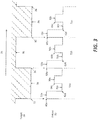
- a portion of an illustrative output signal pulse train 50 (hereinafter "output"), comprising a plurality of portions 51a, 51b, 51c comprising respective ones of pulses 52a-52c, 54a-54c, 56a-56c provided in accordance with a predetermined protocol is generated in response to a sensor (not shown) detecting one or more characteristics and/or one or more features (e.g., one or more mechanical features) of a target 30.
- Pulses 52a-52c may be collectively referred to herein as pulse 52 or first pulse 52.
- Pulses 54a-54c may be collectively referred to herein as pulse 54 or second pulse 54.
- Pulses 56a-56c may be collectively referred to herein as pulse 56 or third pulse 56.
- target 30 is shown as a portion of a gear tooth wheel.
- output 50 Is generated In response to target 30 moving in a first direction (indicated by reference arrow 35) relative to the sensor.
- direction 35 is sometimes referred to as a right movement or right rotation of the target 30 relative to the sensor.
- sensor 2 may generate output 50 in response to detecting characteristics and features of target 30. It should be appreciated that output 50 may be generated in response to target 30 moving in any direction relative to the sensor (i.e., left, right, toward or away from the sensor).
- target 30 has a plurality of teeth 34, each of which has a first edge 32 and a second edge 36.
- a sensor e.g., sensor 2 of FIGs. 1-2
- the sensor when teeth 34 of target 30 pass by a sensor (e.g., sensor 2 of FIGs. 1-2 ), the sensor generates output 50.
- target 30 may be a ring magnet and when a pole pare of the ring magnet passes by the sensor, the sensor generates output 50.
- target 30 is a magnetic latch or switch
- the sensor when an edge of the magnetic latch passes by the sensor, the sensor generates output 50. It should be understood that target 30 may be a variety of different devices and the sensor may generate output 50 in response to various features of target 30.
- Output 50 comprises a plurality of pulse train portions 51a, 51b, 51c, (collectively referred to herein as portions 51) with each portion 51 Including respective ones of the plurality of pulses 52, 54, 56 (i.e., first pulse 52, second pulse, 54, third pulse 56).
- Each pulse 52, 54, 56 is generated in accordance with a pulse width protocol which allows coding of information about the target 30 and/or sensor, including but not limited to speed, direction, positional data, diagnostic data, airgap data, device status and test mode information.
- Each of the plurality of pulses 52, 54, 56 within a single portion 51 can have varying amplitudes and varying widths.
- the amplitude and width of a pulse, as well as the position may be used to code the information and indicate specific characteristics and/or features of a target 30 and/or a sensor generating the pulse train.
- first pulses 52 may be used to convey different Information than second pulses 54 or third pulses 56.
- second pulses 54 and third pulses 56 may be used to convey different information from each other and first pulses 52.
- each of the pulses 52, 54, 56 may be generated with a predetermined amplitude to indicate specific characteristics and/or features of or associated with a target and/or sensor.
- amplitude as used herein may refer to a level or height of pulses 52, 54, 56 in output 50.
- Pulse amplitude may also be used to identify a position of the pulse in the output signal pulse train (e.g., first pulses 52, second pulses 54, third pulses 56).
- first pulse 52 may be generated in response to a first feature (e.g., an edge 32, 36,) of target 30).
- the first pulse 52 is generated with a first amplitude 60 (e.g., first level, high level) that is equal to or greater than a first amplitude threshold.
- the first amplitude threshold is a threshold value, level or height that is used to indicate that pulse 52 is the first pulse in output signal pulse train portions 51a, 51b, 51c.
- first pulse 52 in each portion 51a, 51b, 51c corresponds to either a rising edge 32 or falling edge 36 of a tooth 34.
- first pulse 52 having the first amplitude 60 indicates the beginning of a new portion 51 of output signal pulse train 50.
- the rising edge of first pulse 52 represents additional data such as target speed or frequency.
- the time between first pulse 52a of first portion 51a and first pulse 52b of second portion 51b may be used to determine the speed or frequency at which the target 30 is moving or rotating.
- a second pulse 54 may be generated in response to a second feature or other characteristics of target 30.
- second pulse 54 is generated having a second amplitude 62 (e.g., second level, low level) that is greater than or equal to a second amplitude threshold.
- the second amplitude threshold is a threshold value, level or height that is used to indicate that pulse 54 is the second pulse in output signal pulse train portions 51a, 51b, 51c.
- the second amplitude 62 may be Inverted (e.g., low pulse, low amplitude) with respect to first amplitude 60.
- second pulse 54 follows first pulse 52 and its amplitude 62 falls to a reduced (or sometimes minimum) amplitude of output 50.
- second pulse 54 is inverted as compared with first pulse 52. It should thus be understood that the widths of both high and low portions of output pulse train 50 are used to convey information in the pulse width protocol.
- third pulse 56 may be generated In response to a third feature or characteristic of target 30.
- third pulse 56 is generated with a third amplitude 64 (e.g., third level, middle level) that is greater than or equal to a third amplitude threshold (i.e., middle amplitude).
- the third amplitude threshold is a threshold value, level or height that is used to indicate that pulse 56 Is the third pulse in output signal pulse train portions 51a, 51b, 51c.
- the third amplitude 64 may be less than first amplitude 60 and inverted with respect to second amplitude 62.
- third pulse 56 follows second pulse 54 and its amplitude rises to a third amplitude 64, which is less than the first amplitude 60 of first pulse 52.
- FIG. 3 only shows each portion 51 of output 50 having three pulses 52, 54, 56, it should be appreciated that any number of pulses may be generated within a portion 51 of output 50 depending upon a movement or other characteristic of a target and the needs of a particular application.
- output 50 may include N pulse or N bits in response to a detected feature of target 30.
- a portion of an output pulse train 70 includes pulse train portion 71a, 71b.
- Each of the first pulses 72a-72b, second pulses 74a-74b, third pulses 76a-76b (collectively referred to herein as pulses 72, 74, 76) in first and second pulse train portions 71a, 71b may be generated having a selected one of pulse widths 80a-80c.
- the particular width of each pulse corresponds to a particular bit value which may be used to Indicate a specific feature of a target and/ a sensor or may be used to form a portion of a digital word.
- the width 80a-80c of each pulse may thus be used to provide information such as direction information, airgap properties, a sensor mode, a sensor position and diagnostics data (e.g., automobile safety Integrity level (ASIL) information).
- ASIL automobile safety Integrity level
- each pulse 72, 74, 76 may have up to N different widths.
- each pulse 72, 74, 76 can have one of three different widths, including a first width 80a, a second width 80b and a third width 80c.
- the widths of pulses 72, 74, 76 may be the same.
- the widths of each pulse 72, 74, 76 may be different.
- the widths of two or more pulses 72, 74, 76 may be the same.
- the position of each pulse is first determined (e.g. relative to the delimiter pulse, here corresponding to first pulse 72 followed by second pulse 74 and third pulse 76) and then the width 80 of the pulse is determined. For example, after the first feature of the target is detected and pulse 72 is identified as the first pulse, a width 80 (e.g., first width 80a, second width 80b, third width 80c) of first pulse 72 and each successive pulse 74, 76 may be measured.
- the width 80 can be used in combination with the positon of the particular pulse to provide specific information. For example, first pulse 72 and second pulse 74 may have the same width 80 but provide different Information.
- Table 1 An illustrative base three (3) pulse width protocol Is shown to provide state information.
- each pulse 72, 74, 76 may be designated or assigned to provide predetermined information, such as state information.
- Each state may correspond to a characteristic or feature of a target or a sensor.
- state information may be generated and used for applications functioning in mission mode (e.g., normal mode) and provide details on particular devices during device operation.
- first pulse 72 Is designated to provide direction information of a target
- second pulse 74 is designated to provide airgap information between the target and a sensor
- third pulse 76 is designated to provide sensor mode information.
- each pulse 72, 74, 76 is shown having one of three widths 80a, 80b, 80c.
- output pulse train portions 71a, 71b each have three pulses (i.e. pulses 72a, 74a, 76a, 72b, 74b, 76b, respectively) with each of the pulses 72a, 74a, 76a, 72b, 74b, 76b, having one of three possible widths 80a, 80b, 80c
- each output pulse train portion 71a, 71b can provide up to nine different states or types of information.
- first pulse 72 may be generated in response to a first feature (e.g., first rising edge or first failing edge) of a target with one of three widths 80a, 80b, 80c (here indicated by the dashed downward arrow).
- first pulse 72 is designated to provide direction in which the target is moving.
- first width 80a indicates a positive direction
- second width 80b indicates a negative direction
- third width 80c indicates no direction.
- Second pulse 74 can be designated to provide airgap information between a target and sensor.
- second pulse 74 with a first width 80a indicates an airgap feature in a predetermined acceptable range
- a second width 80b indicates an airgap feature outside the predetermined acceptable range and may cause an alert or flag to be issued.
- second pulse 74 having a third pulse 80c may indicate an airgap reserve and an airgap reserve (AR) signal can be generated.
- airgap reserve may refer to a reserve bit or extra bit and be reserved for a future use.
- Third pulse 76 can be designated to provide sensor mode information.
- third pulse 76 with a first width 80a indicates sensor mode 0, while third pulse 76 with a second width 80b indicates sensor mode 1, and third pulse 76 with a third width 80c indicates sensor mode 2.
- Table 1 provides but one Illustrative embodiment and that any number of states and types of information can be designated according the number of pulses in output 70 and the type of information a particular device or application requests to be monitored or detected (e.g., diagnostics, ASIL, device status, etc.,).
- pulse widths 80a, 80b, 80c of each of the pulses 72, 74, 76 represent a corresponding a logic value, such as a logical data bit.
- the widths 80 of each pulse 72, 74, 76 In output 70 may be measured and the corresponding logic value determined for each pulse 72, 74, 76.
- a first width 80a may be a first logic value
- a second width 80b may be a second logic value
- a third width 80c may be a third logic value in a digital data stream.
- output 70 can be represented as a digital data string (i.e., a stream of data bits with each of the data bits having one of three logic values).
- a stream of data bits can be generated with each of the data bits having one of two logical values.
- the widths 80 may be measured as the pulses 72, 74, 76 are received, for example as they are received by receiver 10 from sensor 2 of FIGs. 1-2 . In other embodiments, the widths 80 may be measured once an entire portion 71 of output 70 has been transmitted from a sensor to a receiver.
- portion 71 of output 70 may be a serial data train representing a data word with a base N, corresponding to N number of potential pulse widths 80 (here shown as a base 3 with 3 potential pulse widths).
- Each word can be a code associated with a characteristic or feature of a target or a sensor.
- a pulse width protocol (base 3) for generating data words Is provided.
- Table 2 Pulse Width Protocol (base 3) Data Word Code First Pulse Second Pulse Third 0 0 0 0 1 0 1 0 2 0 2 0 3 0 1 1 4 0 1 2 5 0 2 1 6 0 2 2 7 1 0 2 8 1 1 0 9 1 2 0 10 1 1 1 1 11 1 1 2 12 1 2 1 13 1 2 2 14 2 0 0 15 2 1 0 16 2 2 2 0 17 2 1 1 18 2 1 2 19 2 2 1 20 2 2 2 2 2 2 2 2 2 2 2
- output 70 having three pulses 72, 74, 76, with each pulse having three potential pulse widths 80a, 80b, 80c can provide up to twenty different logic values (i.e., code) or data words.
- Each logic value may be associated with test or diagnostics information for a device or application.
- logic values can be associated with output codes for a built-in test (BIT) or a test at a probe of a device or application.
- Logic values may be associated with an output 70 received from various types of sensors, including but not limited to an accelerometer, a gyroscope, a gas sensor, a pressure sensor, and a temperature sensor.
- a receiver e.g., receiver 10 of FIGs. 1-2
- output 70 may have a maximum frequency limit or bound depending on the number of pulses 72, 74, 76 generated in portion 71 and the maximum width 80 used for each pulse in the respective portion 71.
- the maximum frequency of a target or data stream is based on the total number of pulses in portion 71 of output signal 70 multiplied by the maximum pulse width 80. If the target or data stream exceeds this frequency there may be data collision between adjacent portions 71, such as between a first portion 71a and a second portion 71b.
- the maximum frequency limit establishes a threshold to avoid data collision within output 70.
- a time out function may be generated to ignore the first rising edge of 72a.
- a time out function may be generated to ignore the first rising edge of 72a.
- receiver 10 of FIGs. 1-2 identifies first edge of first pulse 72a it may initiate a timer with a predetermined time threshold to track or count until the next rising edge is Identified In the data bits.
- the predetermine time threshold limits the amount of time the timer counts to identify potential edge error detections. Thus, if the next rising edge is not identified within the predetermined time threshold, the receiver may flag the first rising edge as an edge error and stop the timer until a next rising edge is identified.
- the sensor system 2 can quickly recover from the error signal and also Identify edge errors.
- the predetermined time threshold may allow the system not to get stuck in a continuous timer or lock up when an edge error is detected.
- the predetermined time threshold may be used in consecutive pulse widths to identify errors within a single portion 71 of output signal 70.
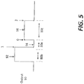
- an output pulse portion 90 includes a first pulse 92 having a width 80b corresponding to a logic value 1, a second pulse 94 having a width 80a corresponding to a logic value 0 and a third pulse 96 having a width 80c corresponding to a logic value 2.
- illustrative pulse train portion 90 comprises a series of three (3) pulses representing logic values 1, 0, 2 respectively.
- a first pulse 92 having logic value 1 indicates that the direction of the target is negative with respect to the sensor.
- a second pulse 94 having logic value 0 indicates that the airgap between the target and sensor is within a predetermined acceptable range.
- a third pulse 96 having logic value 2 indicates that the sensor is in mode 2 or some other function.
- pulse train portion 90 with pulses 92, 94, 96 having logic values 1, 0, 2 respectively corresponds to a code 7 or a 7 th word.
- This data may correspond to a particular diagnostics, test function or some other function.
- output pulse train portion 90 may be used as both state and/or word information depending on a particular application suing the information. For example, both state information and words may be used simultaneously generated and transmitted on the same signal path for different applications.
- output 90 may be received and translated by a receiver. The receiver may translate the Information and provide it to different applications.
- a first application running In mission mode may interpret the logic values 1, 0, 2 as state information, including the negative direction of the target, the acceptable airgap properties and sensor mode 2.
- a second application running in test mode may interpret the same logic values (1, 0, 2) as code 7 or a 7 th word.
- magnetic field sensor is used to describe a circuit that uses a magnetic field sensing element, generally in combination with other circuits.
- Magnetic field sensors are used in a variety of applications, including, but not limited to, an angle sensor that senses an angle of a direction of a magnetic field, a current sensor that senses a magnetic field generated by a current carried by a current-carrying conductor, a magnetic switch that senses the proximity of a ferromagnetic object, a rotation detector that senses passing ferromagnetic articles, for example, magnetic domains of a ring magnet or a ferromagnetic target (e.g., gear teeth) where the magnetic field sensor is used in combination with a back-biased or other magnet, and a magnetic field sensor that senses a magnetic field density of a magnetic field.
- an angle sensor that senses an angle of a direction of a magnetic field
- a current sensor that senses a magnetic field generated by a current carried by a current-carrying conductor
- a magnetic switch that
- magnetic field sensing element is used herein, to describe a variety of electronic elements that can sense a magnetic field.
- the magnetic field sensing element can be, but is not limited to, a Hall effect element, a magnetoresistance element, or a magnetotransistor.
- Hall effect elements for example, a planar Hall element, a vertical Hall element, and a Circular Vertical Hall (CVH) element.
- magnetoresistance elements for example, a semiconductor magnetoresistance element such as indium Antimonide (InSb), a giant magnetoresistance (GMR) element, for example, a spin valve, an anisotropic magnetoresistance element (AMR), a tunneling magnetoresistance (TMR) element, and a magnetic tunnel Junction (MTJ).
- the magnetic field sensing element may be a single element or, alternatively, may include two or more magnetic field sensing elements arranged in various configurations, e.g., a half bridge or full (Wheatstone) bridge.
- the magnetic field sensing element may be a device made of a type IV semiconductor material such as Silicon (Si) or Germanium (Ge), or a type III-V semiconductor material like Gallium-Arsenide (GaAs) or an Indium compound, e.g., Indium-Antimonide (InSb).
- a type IV semiconductor material such as Silicon (Si) or Germanium (Ge)
- a type III-V semiconductor material like Gallium-Arsenide (GaAs) or an Indium compound, e.g., Indium-Antimonide (InSb).
- some of the above-described magnetic field sensing elements tend to have an axis of maximum sensitivity parallel to a substrate that supports the magnetic field sensing element, and others of the above-described magnetic field sensing elements tend to have an axis of maximum sensitivity perpendicular to a substrate that supports the magnetic field sensing element.
- planar Hall elements tend to have axes of sensitivity perpendicular to a substrate
- metal based or metallic magnetoresistance elements e.g., GMR, TMR, AMR
- vertical Hall elements tend to have axes of sensitivity parallel to a substrate.
- processor is used to describe an electronic circuit that performs a function, an operation, or a sequence of operations.
- the function, operation, or sequence of operations can be hard coded into the electronic circuit or soft coded by way of instructions held in a memory device.
- a "processor can perform the function, operation, or sequence of operations using digital values or using analog signals.
- the "processor” can be embodied in an application specific integrated circuit (ASIC), which can be an analog ASIC or a digital ASIC. In some embodiments, the "processor” can be embodied in a microprocessor with associated program memory. In some embodiments, the "processor” can be embodied in a discrete electronic circuit, which can be an analog or digital.
- ASIC application specific integrated circuit
- module is sometimes used to describe a "processor.”
- a processor can contain internal processors or internal modules that perform portions of the function, operation, or sequence of operations of the processor.
- a module can contain internal processors or internal modules that perform portions of the function, operation, or sequence of operations of the module.
- embodiments of the disclosure herein may be configured as a system, method, or combination thereof. Accordingly, examples may be comprised of various means including entirely of hardware, entirely of software, or any combination of hardware and software. Furthermore, examples may take the form of a computer program product on a computer-readable storage medium having computer readable program instructions (e.g., computer software) embodied in the storage medium. Any suitable non-transitory computer-readable storage medium may be utilized.
Landscapes
- Physics & Mathematics (AREA)
- Nonlinear Science (AREA)
- Condensed Matter Physics & Semiconductors (AREA)
- General Physics & Mathematics (AREA)
- Transmission And Conversion Of Sensor Element Output (AREA)
- Measurement Of Length, Angles, Or The Like Using Electric Or Magnetic Means (AREA)
Claims (20)
- In einem Sensor (2) zum Detektieren eines Zieles (4; 30), ein Verfahren, das Folgendes umfasst:Detektieren eines ersten Merkmals des Ziels (4; 30);als Reaktion auf das Detektieren des ersten Merkmals, Erzeugen eines Ausgangssignalimpulsfolgeabschnitts (9; 51; 71; 90), der zwei oder mehr Impulse (11; 52, 54, 56; 72, 74, 76; 92, 94, 96) umfasst, wobei mindestens zwei der Impulse unterschiedliche Amplituden aufweisen und jeder der zwei oder mehr Impulse eine Breite (80) aufweist, die einem Logikwert entspricht, wobei mindestens ein erster der zwei oder mehr Impulse (11; 52, 54, 56; 72, 74, 76; 92, 94, 96) eine hohe Amplitude aufweist und mindestens ein zweiter der zwei oder mehr Impulse, der direkt auf den ersten der zwei oder mehr Impulse folgt, eine niedrige Amplitude aufweist;Messen der Breiten der zwei oder mehr Impulse in dem Ausgangssignalimpulsfolgeabschnitt als Reaktion darauf, dass mindestens einer der zwei oder mehr Impulse eine erste Amplitudenschwelle erreicht; undBestimmen eines Logikwertes für jede der gemessenen Breiten, wobei der Ausgangssignalimpulsfolgeabschnitt einem Datenwort entspricht, das auf den bestimmten Logikwerten für jede der gemessenen Breiten der zwei oder mehr Impulse basiert, und der Ausgangssignalimpulsfolgeabschnitt mindestens N Impulse beinhaltet und das Datenwort ein Basis-N-Datenwort ist.
- Verfahren nach Anspruch 1, wobei mindestens zwei der Impulse unterschiedliche Breiten aufweisen, die unterschiedlichen Logikwerten entsprechen.
- Verfahren nach Anspruch 1, wobei der Ausgangssignalimpulsfolgeabschnitt drei Impulse umfasst, wobei ein erster Impuls eine erste Breite (80a) aufweist, die einem ersten Logikwert entspricht, ein zweiter Impuls eine zweite Breite (80b) aufweist, die einem zweiten Logikwert entspricht, und ein dritter Impuls eine dritte Breite (80c) aufweist, die einem dritten Logikwert entspricht.
- Verfahren nach Anspruch 1, wobei der Ausgangssignalimpulsfolgeabschnitt 3 Impulse beinhaltet und das Datenwort ein Basis-3-Datenwort ist.
- Verfahren nach Anspruch 1, wobei mindestens ein Ausgang des Vorrichtungszustands einem Zustand des Zielobjekts oder einen Zustand eines Sensors, der das Zielobjekt überwacht, entspricht.
- Verfahren nach Anspruch 1, das ferner das Bestimmen einer Frequenz des Zielobjekts basierend auf den gemessenen Breiten der zwei oder mehr Impulse umfasst.
- Verfahren nach Anspruch 1, das ferner das Bestimmen von Luftspalteigenschaften zwischen dem Zielobjekt und einem Sensor, der das Zielobjekt überwacht, basierend auf den gemessenen Breiten der zwei oder mehr Impulse umfasst.
- Verfahren nach Anspruch 1, das ferner Folgendes umfasst:als Reaktion auf das Detektieren des ersten Merkmals, Detektieren eines zweiten Merkmals nach einer vorher festgelegten Zeitschwelle; undErzeugen einer Timeout-Funktion reagierend auf das Überschreiten der vorher festgelegten Zeitschwelle, wobei die Timeout-Funktion das erste Merkmal ignoriert und auf die Detektion eines dritten Merkmals wartet.
- Verfahren nach Anspruch 1, das ferner das Erzeugen eines ersten Impulses in dem Ausgangssignalimpulsfolgeabschnitt reagierend auf das detektierte erste Merkmal umfasst, wobei das erste Merkmal eine Vorderflanke (32, 36) des Zielobjekts und des ersten Impulses ist, mit vorher festgelegten Charakteristika, um die Vorderflanke zu identifizieren.
- Verfahren nach Anspruch 9, das ferner das Identifizieren des ersten Impulses basierend darauf, dass der erste Impuls eine Amplitude aufweist, die größer als eine oder gleich einer Amplitudenschwelle ist, umfasst.
- System zum Bereitstellen von Informationen über ein Zielobjekt (4; 30) basierend auf Impulsbreiten (80), wobei das System Folgendes umfasst:
einen Sensor, der für Folgendes eingerichtet ist:Detektieren eines ersten Merkmals des Zielobjekts (4; 30);als Reaktion auf das detektierte erste Merkmal, Erzeugen eines Ausgangssignalimpulsfolgeabschnitts (9; 51; 71; 90), der mindestens einen Impulsfolgeabschnitt umfasst, wobei jeder Impulsfolgeabschnitt zwei oder mehr Impulse (11; 52, 54, 56; 72, 74, 76; 92, 94, 96) umfasst, wobei mindestens zwei der Impulse unterschiedliche Amplituden aufweisen und jeder der zwei oder mehr Impulse eine Breite (80) aufweist, die einem Logikwert entspricht, wobei mindestens ein erster der zwei oder mehr Impulse (11; 52, 54, 56; 72, 74, 76; 92, 94, 96) eine hohe Amplitude aufweist und mindestens ein zweiter der zwei oder mehr Impulse, der direkt auf den ersten der zwei oder mehr Impulse folgt, eine niedrige Amplitude aufweist;Messen der Breiten der zwei oder mehr Impulse in dem Ausgangssignalimpulsfolgeabschnitt als Reaktion darauf, dass mindestens einer der zwei oder mehr Impulse eine erste Amplitudenschwelle erreicht;Bestimmen eines Logikwertes für jede der gemessenen Breiten, wobei der Ausgangssignalimpulsfolgeabschnitt einem Datenwort entspricht, das auf den bestimmten Logikwerten für jede der gemessenen Breiten der zwei oder mehr Impulse basiert, und der Ausgangssignalimpulsfolgeabschnitt mindestens N Impulse beinhaltet und das Datenwort ein Basis-N-Datenwort ist. - System nach Anspruch 11, wobei der Sensor einen Magnetfeldsensor umfasst.
- System nach Anspruch 12, wobei der Magnetfeldsensor eine integrierte Einzelchip-Schaltung mit Halleffektsensor umfasst.
- System nach Anspruch 12, wobei der Magnetfeldsensor ein oder mehrere Halleffektelemente umfasst.
- System nach Anspruch 12, wobei der Magnetfeldsensor drei Halleffektelemente umfasst, wobei jedes der drei Halleffektelemente entlang Flanken oder an Eckpunkten eines gleichseitigen Dreiecks innerhalb des Sensors positioniert ist.
- System nach Anspruch 15, wobei die drei Halleffektelemente konfiguriert sind, ein Magnetprofil des Zielobjekts gleichzeitig, aber an unterschiedlichen Stellen innerhalb des Sensors zu detektieren.
- Sensor nach Anspruch 12, wobei der Sensor eine oder mehrere Detektionsschaltungen (5) umfasst, die mit dem Magnetfeldsensor gekoppelt sind.
- System nach Anspruch 17, wobei die eine oder die mehreren Detektionsschaltungen konfiguriert sind, mindestens eines von Folgendem zu detektieren: (a) einen Parameter einer Umgebung, in der der Sensor eingerichtet ist, (b) das erste Merkmal des Zielobjekts und (c) einen Parameter einer Beziehung zwischen dem Sensor und dem Zielobjekt.
- System nach Anspruch 17, wobei die eine oder die mehreren Detektionsschaltungen konfiguriert sind, eine Richtung des Zielobjekts relativ zu dem Sensor zu detektieren.
- System nach Anspruch 17, wobei die eine oder die mehreren Detektionsschaltungen konfiguriert sind, Luftspalteigenschaften zwischen dem Zielobjekt und dem Sensor zu detektieren.
Applications Claiming Priority (2)
| Application Number | Priority Date | Filing Date | Title |
|---|---|---|---|
| US15/010,453 US10495700B2 (en) | 2016-01-29 | 2016-01-29 | Method and system for providing information about a target object in a formatted output signal |
| PCT/US2017/012241 WO2017131934A1 (en) | 2016-01-29 | 2017-01-05 | Method and system for providing information about a target object in a formatted output signal |
Publications (2)
| Publication Number | Publication Date |
|---|---|
| EP3408937A1 EP3408937A1 (de) | 2018-12-05 |
| EP3408937B1 true EP3408937B1 (de) | 2021-11-24 |
Family
ID=57915083
Family Applications (1)
| Application Number | Title | Priority Date | Filing Date |
|---|---|---|---|
| EP17702179.7A Active EP3408937B1 (de) | 2016-01-29 | 2017-01-05 | Verfahren und system zur bereitstellung von informationen über ein zielobjekt in einem formatierten ausgangssignal |
Country Status (3)
| Country | Link |
|---|---|
| US (1) | US10495700B2 (de) |
| EP (1) | EP3408937B1 (de) |
| WO (1) | WO2017131934A1 (de) |
Families Citing this family (31)
| Publication number | Priority date | Publication date | Assignee | Title |
|---|---|---|---|---|
| WO2018048768A1 (en) | 2016-09-08 | 2018-03-15 | Allegro Microsystems, Llc | Signalling of faults in a speed sensor |
| DE102016125183B4 (de) | 2016-12-21 | 2022-01-27 | Infineon Technologies Ag | Vorrichtungen zum Codieren und Decodieren von Radgeschwindigkeitssensorsignalen und Verfahren zum Kommunizieren von codierten Radgeschwindigkeitssensorsignalen |
| US10480957B2 (en) | 2017-07-20 | 2019-11-19 | Allegro Microsystems, Llc | Magnetic field sensor to detect direction of angular rotation of a rotating magnetic structure, speed of the rotating magnetic structure or fault |
| US10571301B2 (en) | 2017-07-20 | 2020-02-25 | Allegro Microsystems, Llc | Frequency of an output signal of a magnetic field sensor to detect speed and direction of angular rotation of a rotating magnetic structure or a fault |
| US10473486B2 (en) | 2017-07-20 | 2019-11-12 | Allegro Microsystems, Llc | Duty cycle of an output signal of a magnetic field sensor to detect speed and direction of angular rotation of a rotating magnetic structure or a fault |
| US10436606B2 (en) | 2017-07-20 | 2019-10-08 | Allegro Microsystems, Llc | Magnetic field sensor to detect speed and direction of angular rotation of a rotating magnetic structure |
| US10598514B2 (en) | 2017-07-20 | 2020-03-24 | Allegro Microsystems, Llc | Magnetic field sensor to detect speed of angular rotation of a rotating magnetic structure, direction of the rotating magnetic structure or fault |
| US10782366B2 (en) | 2017-10-11 | 2020-09-22 | Allegro Microsystems, Llc | Multi-channel sensor output signal protocols |
| US10656170B2 (en) | 2018-05-17 | 2020-05-19 | Allegro Microsystems, Llc | Magnetic field sensors and output signal formats for a magnetic field sensor |
| US10578679B2 (en) | 2018-06-18 | 2020-03-03 | Allegro Microsystems, Llc | Magnetic field sensors having virtual signals |
| US10598739B2 (en) | 2018-06-18 | 2020-03-24 | Allegro Microsystems, Llc | Magnetic field sensors having virtual signals |
| US10866118B2 (en) | 2018-06-18 | 2020-12-15 | Allegro Microsystems, Llc | High resolution magnetic field sensors |
| US10908229B2 (en) | 2018-06-18 | 2021-02-02 | Allegro Microsystems, Llc | Regulation of coefficients used in magnetic field sensor virtual signal generation |
| US10725122B2 (en) | 2018-07-20 | 2020-07-28 | Allegro Microsystems, Llc | Ratiometric sensor output topology and methods |
| DE102018215938B4 (de) * | 2018-09-19 | 2024-11-07 | Infineon Technologies Ag | Hochauflösungsmodus für einen Magnetfeldsensor |
| US11686597B2 (en) | 2019-06-07 | 2023-06-27 | Allegro Microsystems, Llc | Magnetic field sensors and output signal formats for magnetic field sensors |
| US11942831B2 (en) | 2020-01-15 | 2024-03-26 | Allegro Microsystems, Llc | Three-phase BLDC motor driver/controller having diagnostic signal processing |
| US11194004B2 (en) | 2020-02-12 | 2021-12-07 | Allegro Microsystems, Llc | Diagnostic circuits and methods for sensor test circuits |
| US11029370B1 (en) | 2020-05-22 | 2021-06-08 | Allegro Microsystems, Llc | Sensor output control methods and apparatus |
| US12107710B2 (en) | 2020-11-19 | 2024-10-01 | Allegro Microsystems, Llc | Sensor signaling of absolute and incremental data |
| US11762043B2 (en) | 2021-03-11 | 2023-09-19 | Allegro Microsystems, Llc | High resolution magnetic field sensors |
| US11885645B2 (en) | 2021-06-17 | 2024-01-30 | Allegro Microsystems, Llc | Supply voltage configurable sensor |
| CN113873717A (zh) * | 2021-09-29 | 2021-12-31 | 擎茂微电子(深圳)有限公司 | 一种电源载波控制led灯串的数据控制协议 |
| DE102021212324B4 (de) * | 2021-11-02 | 2024-10-17 | Continental Automotive Technologies GmbH | Verfahren zur Auswertung von Radsensorsignalen, Anordnung dazu und Bremssystem umfassend die Anordnung |
| US12266603B2 (en) | 2022-05-03 | 2025-04-01 | Allegro Microsystems, Llc | Semiconductor device to reduce signal loss in a transmission line |
| US12332273B2 (en) | 2022-05-18 | 2025-06-17 | Allegro Microsystems, Llc | High resolution sensing protocol |
| US12348243B2 (en) | 2022-05-18 | 2025-07-01 | Allegro Microsystems, Llc | Method and apparatus for transmitting data concurrently with a pulse-encoded signal |
| DE102022206825A1 (de) | 2022-07-04 | 2024-01-04 | Continental Automotive Technologies GmbH | Raddrehzahlsensorschnittstelle mit Manchester Protokoll |
| US12104900B2 (en) | 2022-09-29 | 2024-10-01 | Allegro Microsystems, Llc | Sensor with estimated real-time parameter data |
| US12407549B2 (en) | 2023-11-06 | 2025-09-02 | Allegro Microsystems, Llc | Output signal protocol |
| US12449279B2 (en) | 2024-02-07 | 2025-10-21 | Allegro Microsystems, Llc | Dynamic resolution sensor |
Family Cites Families (103)
| Publication number | Priority date | Publication date | Assignee | Title |
|---|---|---|---|---|
| US3304434A (en) | 1965-06-01 | 1967-02-14 | Bunker Ramo | Position control system employing pulse producing means indicative of magnitude and direction of movement |
| JPS5113795B2 (de) | 1972-02-03 | 1976-05-04 | ||
| DE2518054C2 (de) | 1975-04-23 | 1984-08-02 | Siemens AG, 1000 Berlin und 8000 München | Anordnung zur Bestimmung des Drehsinns einer Drehbewegung |
| JPS52127005A (en) | 1976-04-16 | 1977-10-25 | Pioneer Electronic Corp | Bidirectional data communication system |
| GB2018538B (en) | 1978-04-05 | 1982-07-28 | Hawker Siddeley Dynamics Eng | Apparatus for the treatment of frequency signals |
| JPS54148578A (en) | 1978-04-18 | 1979-11-20 | Nec Corp | Rotating direction detector |
| US4513403A (en) | 1982-08-04 | 1985-04-23 | Exploration Logging, Inc. | Data encoding and synchronization for pulse telemetry |
| US4642555A (en) | 1985-01-31 | 1987-02-10 | Sperry Corporation | Differential capacitance detector |
| DE3535842A1 (de) | 1985-10-08 | 1987-04-09 | Bosch Gmbh Robert | Drehzahlmesswertgeberschaltung |
| US4649796A (en) | 1986-06-18 | 1987-03-17 | The United States Of America As Represented By The Secretary Of The Army | Method and apparatus for setting a projectile fuze during muzzle exit |
| DE3632624C1 (de) | 1986-09-25 | 1988-03-10 | Balluff Gebhard Feinmech | Stoerfeldunempfindlicher Naeherungsschalter |
| GB8711559D0 (en) | 1987-05-15 | 1987-06-17 | Ssd Ltd | Shaft encoders |
| JPH0612266B2 (ja) | 1987-05-30 | 1994-02-16 | 株式会社安川電機 | 多回転式絶対値エンコ−ダ |
| JP2574873B2 (ja) | 1988-08-24 | 1997-01-22 | 株式会社日立製作所 | 位置あるいは速度検出装置 |
| JPH02116753A (ja) | 1988-10-26 | 1990-05-01 | Mitsubishi Electric Corp | 回転方向検出装置 |
| JPH02149013A (ja) | 1988-11-30 | 1990-06-07 | Toshiba Corp | 発振回路 |
| JPH0329817A (ja) | 1989-06-28 | 1991-02-07 | Fanuc Ltd | ワイヤレス手動エンコーダ |
| JP2522214B2 (ja) | 1989-10-05 | 1996-08-07 | 日本電装株式会社 | 半導体装置およびその製造方法 |
| DE9010488U1 (de) | 1990-07-12 | 1990-09-13 | Siemens AG, 80333 München | Schaltungsanordnung zur Verbesserung der zeitlichen Auflösung aufeinanderfolgender impulsförmiger Signale |
| DE4031560C2 (de) | 1990-10-05 | 1993-10-14 | Dieter Prof Dr Ing Seitzer | Stromsensor mit magnetfeldempfindlichen Bauelementen und Verwendung |
| KR940004952B1 (ko) | 1991-11-08 | 1994-06-07 | 주식회사 금성사 | 직류모터 가동 제어장치 |
| EP0593925B1 (de) | 1992-10-21 | 1997-12-29 | Robert Bosch Gmbh | Vorrichtung zum Erfassen der Bewegung eines bewegbaren Teils |
| JPH06273437A (ja) | 1993-03-22 | 1994-09-30 | Yazaki Corp | 回転検出装置 |
| JP2812639B2 (ja) | 1993-06-15 | 1998-10-22 | 三菱電機株式会社 | 経路探索システム,及び経路探索方法 |
| US5442313A (en) | 1994-05-27 | 1995-08-15 | The Torrington Company | Resolution multiplying circuit |
| US5781005A (en) | 1995-06-07 | 1998-07-14 | Allegro Microsystems, Inc. | Hall-effect ferromagnetic-article-proximity sensor |
| US5696790A (en) | 1995-10-04 | 1997-12-09 | Tut Systems, Inc. | Method and apparatus for time dependent data transmission |
| US6297627B1 (en) | 1996-01-17 | 2001-10-02 | Allegro Microsystems, Inc. | Detection of passing magnetic articles with a peak-to-peak percentage threshold detector having a forcing circuit and automatic gain control |
| US6525531B2 (en) | 1996-01-17 | 2003-02-25 | Allegro, Microsystems, Inc. | Detection of passing magnetic articles while adapting the detection threshold |
| US6242908B1 (en) | 1996-01-17 | 2001-06-05 | Allegro Microsystems, Inc. | Detection of passing magnetic articles while adapting the detection threshold |
| US5761206A (en) | 1996-02-09 | 1998-06-02 | Interactive Technologies, Inc. | Message packet protocol for communication of remote sensor information in a wireless security system |
| US6788221B1 (en) | 1996-06-28 | 2004-09-07 | Synaptics (Uk) Limited | Signal processing apparatus and method |
| DE19634714B4 (de) | 1996-08-28 | 2007-08-16 | Continental Teves Ag & Co. Ohg | Anordnung für ein Kraftfahrzeug-Regelungssystem |
| DE19634715A1 (de) | 1996-08-28 | 1998-03-05 | Teves Gmbh Alfred | Anordnung zur Erfassung des Drehverhaltens eines Rades |
| US5912347A (en) | 1996-09-30 | 1999-06-15 | Mallinckrodt Inc. | Process for preparing a morphinan derivative |
| DE19650935A1 (de) | 1996-12-07 | 1998-06-10 | Teves Gmbh Alfred | Verfahren und Schaltungsanordnung zur Übertragung von Drehzahlinformationen und Zusatzdaten |
| JP4093381B2 (ja) | 1997-04-01 | 2008-06-04 | 株式会社デンソー | 回転センサの検出信号処理装置 |
| JPH1164363A (ja) | 1997-08-25 | 1999-03-05 | Aisin Seiki Co Ltd | 回転検出器 |
| JP2002507751A (ja) | 1998-03-20 | 2002-03-12 | コンティネンタル・テーベス・アクチエンゲゼルシヤフト・ウント・コンパニー・オッフェネ・ハンデルスゲゼルシヤフト | 運動検出用センサ装置 |
| US6242905B1 (en) | 1998-04-23 | 2001-06-05 | Siemens Aktiengesellschaft | Method for identifying the direction of rotation of a wheel using hall probes |
| DE19819265C1 (de) | 1998-04-30 | 1999-08-19 | Micronas Intermetall Gmbh | Verfahren zum Parametrieren einer integrierten Schaltungsanordnung und integrierte Schaltungsanordnung hierfür |
| US20010009367A1 (en) | 1999-02-26 | 2001-07-26 | Dieter Seitzer | Sensor device to record speed and motion direction of an object, especially rotational speed and direction of a rotating object |
| US6278269B1 (en) | 1999-03-08 | 2001-08-21 | Allegro Microsystems, Inc. | Magnet structure |
| DE19912446C1 (de) | 1999-03-19 | 2000-11-09 | Micronas Intermetall Gmbh | Einrichtung zum Einstellen von Betriebsgrößen in mehreren programmierbaren integrierten Schaltungen, insbesondere enthaltend jeweils einen Hallgenerator |
| JP2001043475A (ja) | 1999-07-27 | 2001-02-16 | Nsk Ltd | センサの検出信号の伝送方法 |
| DE19937155A1 (de) | 1999-08-06 | 2001-03-15 | Bosch Gmbh Robert | System zur Erzeugung eines Signals zur Überlagerung von Informationen |
| DE19955758A1 (de) * | 1999-11-19 | 2001-05-31 | Infineon Technologies Ag | Verfahren zur Kommunikation mit einem eingebauten Sensor, insbesondere einem Drehzahlsensor |
| JP4964358B2 (ja) | 1999-12-07 | 2012-06-27 | 株式会社デンソー | 回転センサの検出信号処理装置および回転センサの検出信号出力方法 |
| DE19961504A1 (de) | 1999-12-20 | 2001-06-28 | Bosch Gmbh Robert | Verfahren zur Erkennung von Signalfehlern |
| US6492697B1 (en) | 2000-04-04 | 2002-12-10 | Honeywell International Inc. | Hall-effect element with integrated offset control and method for operating hall-effect element to reduce null offset |
| US6617846B2 (en) | 2000-08-31 | 2003-09-09 | Texas Instruments Incorporated | Method and system for isolated coupling |
| JP3479275B2 (ja) | 2000-10-05 | 2003-12-15 | 株式会社エヌ・ティ・ティ・データ | 航空経路設定装置及び記録媒体 |
| JP4168604B2 (ja) | 2001-05-31 | 2008-10-22 | 日本ゼオン株式会社 | 現像方法及び画像形成方法 |
| US6498474B1 (en) | 2001-06-27 | 2002-12-24 | Kelsey-Hayes Company | Rotational velocity and direction sensing system |
| US6642847B1 (en) | 2001-08-31 | 2003-11-04 | Donald R. Sison | Pool alarm device |
| US6815944B2 (en) | 2002-01-31 | 2004-11-09 | Allegro Microsystems, Inc. | Method and apparatus for providing information from a speed and direction sensor |
| WO2003087845A2 (de) | 2002-04-18 | 2003-10-23 | Continental Teves Ag & Co. Ohg | Verfahren und vorrichtung zur erfassung von ortsverschiebungen und drehbewegungen |
| US20040062362A1 (en) | 2002-09-18 | 2004-04-01 | Yasuyuki Matsuya | Data communication method, data transmitting apparatus, data receiving apparatus, and data transmission program |
| JP2004207477A (ja) | 2002-12-25 | 2004-07-22 | Sanken Electric Co Ltd | ホール素子を有する半導体装置 |
| DE10335153B4 (de) | 2003-07-31 | 2006-07-27 | Siemens Ag | Schaltungsanordnung auf einem Substrat, die einen Bestandteil eines Sensors aufweist, und Verfahren zum Herstellen der Schaltungsanordnung auf dem Substrat |
| JP2005171769A (ja) | 2003-12-08 | 2005-06-30 | Kokusan Denki Co Ltd | エンジンの回転情報検出装置 |
| DE102004007486A1 (de) | 2004-02-13 | 2005-10-27 | Micronas Gmbh | Sensor mit Multiplex-Datenausgang |
| JP2005241268A (ja) | 2004-02-24 | 2005-09-08 | Aisin Seiki Co Ltd | 回転センサ |
| JP2005249488A (ja) | 2004-03-02 | 2005-09-15 | Denso Corp | 回転センサの検出信号処理回路及び検出信号処理装置 |
| US7199579B2 (en) | 2004-03-08 | 2007-04-03 | Allegro Microsystems, Inc. | Proximity detector |
| JP4605435B2 (ja) | 2004-03-24 | 2011-01-05 | アイシン精機株式会社 | 回転検出装置 |
| ITMI20040629A1 (it) | 2004-03-30 | 2004-06-30 | Supercolori S P A | Metodo e prodotto derivante per la preparazione di chips scaglie paste e simili contenenti particelle da additivare a polimeri da stampaggio e vernici |
| US7365530B2 (en) | 2004-04-08 | 2008-04-29 | Allegro Microsystems, Inc. | Method and apparatus for vibration detection |
| US20050225318A1 (en) | 2004-04-08 | 2005-10-13 | Bailey James M | Methods and apparatus for vibration detection |
| US6822588B1 (en) * | 2004-04-15 | 2004-11-23 | Agilent Technologies, Inc. | Pulse width modulation systems and methods |
| US7015832B2 (en) | 2004-05-25 | 2006-03-21 | Bei Sensors & Systems Company, Inc. | Pulse width modulation based digital incremental encoder |
| DE102004025776B3 (de) | 2004-05-26 | 2005-07-21 | Infineon Technologies Ag | Verfahren zur Detektion von Störungen bei der Ermittlung der Drehgeschwindigkeit eines Rotors und Auswerteschaltung |
| US7184876B2 (en) | 2004-06-18 | 2007-02-27 | Siemens Vdo Automotive | Device and process for determining the position of an engine |
| DE502004003709D1 (de) | 2004-11-25 | 2007-06-14 | Alcatel Lucent | Verfahren und Vorrichtung zur Fahrtrichtungserkennung |
| US7236907B2 (en) | 2004-12-22 | 2007-06-26 | Robert Bosch Gmbh | Steering angle sensor assembly with pulse width modulated output signal |
| JP2007170922A (ja) | 2005-12-20 | 2007-07-05 | Denso Corp | 回転検出装置の信号処理回路 |
| US7362094B2 (en) | 2006-01-17 | 2008-04-22 | Allegro Microsystems, Inc. | Methods and apparatus for magnetic article detection |
| EP2049874B1 (de) * | 2006-08-01 | 2010-11-17 | Continental Teves AG & Co. oHG | Sensoranordnung zur präzisen erfassung von relativbewegungen zwischen einem encoder und einem sensor |
| US8063635B2 (en) * | 2006-10-23 | 2011-11-22 | Nxp B.V. | Magnetoresistive sensor with three corners with two wiring connections |
| US8848808B2 (en) * | 2007-03-01 | 2014-09-30 | Lightfleet Corporation | Time domain symbols |
| EP2000813A1 (de) | 2007-05-29 | 2008-12-10 | Ecole Polytechnique Fédérale de Lausanne | Magnetfeldsensor zum Messen der Richtung eines Magnetfelds |
| US7800389B2 (en) | 2007-07-13 | 2010-09-21 | Allegro Microsystems, Inc. | Integrated circuit having built-in self-test features |
| JP2009058240A (ja) | 2007-08-30 | 2009-03-19 | Denso Corp | 回転検出装置 |
| US7923996B2 (en) | 2008-02-26 | 2011-04-12 | Allegro Microsystems, Inc. | Magnetic field sensor with automatic sensitivity adjustment |
| JP4577396B2 (ja) | 2008-04-03 | 2010-11-10 | 株式会社デンソー | 回転検出装置 |
| US8624588B2 (en) | 2008-07-31 | 2014-01-07 | Allegro Microsystems, Llc | Apparatus and method for providing an output signal indicative of a speed of rotation and a direction of rotation as a ferromagnetic object |
| WO2010096367A1 (en) | 2009-02-17 | 2010-08-26 | Allegro Microsystems, Inc. | Circuits and methods for generating a self-test of a magnetic field sensor |
| WO2011011479A1 (en) | 2009-07-22 | 2011-01-27 | Allegro Microsystems, Inc. | Circuits and methods for generating a diagnostic mode of operation in a magnetic field sensor |
| DE112010003022T5 (de) | 2009-07-22 | 2012-08-02 | Ntn Corp. | Fahrzeugsteuergerät und darin verwendetes Drehzahlerkennungsgerät |
| US8577634B2 (en) | 2010-12-15 | 2013-11-05 | Allegro Microsystems, Llc | Systems and methods for synchronizing sensor data |
| US8680846B2 (en) | 2011-04-27 | 2014-03-25 | Allegro Microsystems, Llc | Circuits and methods for self-calibrating or self-testing a magnetic field sensor |
| US9201122B2 (en) | 2012-02-16 | 2015-12-01 | Allegro Microsystems, Llc | Circuits and methods using adjustable feedback for self-calibrating or self-testing a magnetic field sensor with an adjustable time constant |
| US8754640B2 (en) | 2012-06-18 | 2014-06-17 | Allegro Microsystems, Llc | Magnetic field sensors and related techniques that can provide self-test information in a formatted output signal |
| US8860404B2 (en) | 2012-06-18 | 2014-10-14 | Allegro Microsystems, Llc | Magnetic field sensors and related techniques that can provide a self-test using signals and related thresholds |
| US9222990B2 (en) | 2012-06-18 | 2015-12-29 | Allegro Microsystems, Llc | Magnetic field sensors and related techniques that can communicate at least one of three or more potential categories in which one or more characteristic values of a proximity signal responsive to a proximity of a sensed object are categorized |
| US9068859B2 (en) | 2012-06-18 | 2015-06-30 | Allegro Microsystems, Llc | Magnetic field sensors and related techniques provide a self-test by communicating selected analog or digital samples of a proximity signal |
| DE102013209514A1 (de) * | 2013-05-22 | 2014-11-27 | Micronas Gmbh | Dreidimensionaler Hallsensor zum Detektieren eines räumlichen Magnetfeldes |
| US9076272B2 (en) | 2013-05-28 | 2015-07-07 | Infineon Technologies Ag | Wheel speed sensor and interface systems and methods |
| US9088574B2 (en) * | 2013-07-18 | 2015-07-21 | International Business Machines Corporation | Subscriber identity module-based authentication of a wireless device and applications stored thereon |
| KR101540176B1 (ko) | 2014-03-13 | 2015-07-28 | 엘에스산전 주식회사 | 전동기 속도 검출장치 |
| US9651572B2 (en) | 2014-03-19 | 2017-05-16 | Infineon Technologies Ag | Speed sensor device, speed sensor method, electronic control unit and control method |
| DE102014109693A1 (de) * | 2014-07-10 | 2016-01-14 | Micronas Gmbh | Vorrichtung und Verfahren zur berührungslosen Messung eines Winkels |
| CN204989435U (zh) | 2015-07-17 | 2016-01-20 | 中国人民解放军理工大学 | 三棱锥形三维脉冲磁场测量装置 |
-
2016
- 2016-01-29 US US15/010,453 patent/US10495700B2/en active Active
-
2017
- 2017-01-05 EP EP17702179.7A patent/EP3408937B1/de active Active
- 2017-01-05 WO PCT/US2017/012241 patent/WO2017131934A1/en not_active Ceased
Non-Patent Citations (1)
| Title |
|---|
| None * |
Also Published As
| Publication number | Publication date |
|---|---|
| US20170219662A1 (en) | 2017-08-03 |
| EP3408937A1 (de) | 2018-12-05 |
| WO2017131934A1 (en) | 2017-08-03 |
| US10495700B2 (en) | 2019-12-03 |
Similar Documents
| Publication | Publication Date | Title |
|---|---|---|
| EP3408937B1 (de) | Verfahren und system zur bereitstellung von informationen über ein zielobjekt in einem formatierten ausgangssignal | |
| US10481218B2 (en) | Providing information about a target object in a formatted output signal | |
| EP3201634B1 (de) | Verfahren und vorrichtung zur fehlererkennung bei einem magnetfeldsensor | |
| EP3304003B1 (de) | Magnetfeldsensor zur ausrichtungsunabhängigen geschwindigkeits- und richtungsmessung | |
| EP3848675B1 (de) | Magnetfeldsensor mit verbesserter reaktionsimmunität | |
| US9664748B2 (en) | Systems and methods for providing signal encoding representative of a signature region in a target | |
| US10782366B2 (en) | Multi-channel sensor output signal protocols | |
| US10697800B2 (en) | Multi-dimensional measurement using magnetic sensors and related systems, methods, and integrated circuits | |
| US11686597B2 (en) | Magnetic field sensors and output signal formats for magnetic field sensors | |
| US20190113584A1 (en) | Efficient Signal Path Diagnostics For Safety Devices | |
| US20160245893A1 (en) | Detecting sensor error | |
| US11811569B2 (en) | Sensor integrated circuits having a single edge nibble transmission (SENT) output | |
| WO2017160519A1 (en) | Integrated circuit and method for detecting a stress condition in the integrated circuit | |
| US20210247213A1 (en) | Multi-channel quadrature signaling with current mode interface | |
| US7013233B2 (en) | Method and device for the detection of the movement of an element | |
| EP4597118A1 (de) | Sensor zur erfassung der geschwindigkeit eines objekts mit einem oder mehreren magnetfeldsensorelementen und einem zeitabgeleitetem sensorausgabeprotokoll | |
| US12292280B2 (en) | Angle sensor | |
| US11169221B2 (en) | Target alignment and stray field indicator | |
| US10797851B2 (en) | Dual edge synchronization of analog input to reduce switch point jitter | |
| US20250350299A1 (en) | Self-clocking signal protocol | |
| CN114383636A (zh) | 用于传感器的功能安全的稳健信号路径合理性检查 |
Legal Events
| Date | Code | Title | Description |
|---|---|---|---|
| STAA | Information on the status of an ep patent application or granted ep patent |
Free format text: STATUS: UNKNOWN |
|
| STAA | Information on the status of an ep patent application or granted ep patent |
Free format text: STATUS: THE INTERNATIONAL PUBLICATION HAS BEEN MADE |
|
| PUAI | Public reference made under article 153(3) epc to a published international application that has entered the european phase |
Free format text: ORIGINAL CODE: 0009012 |
|
| STAA | Information on the status of an ep patent application or granted ep patent |
Free format text: STATUS: REQUEST FOR EXAMINATION WAS MADE |
|
| 17P | Request for examination filed |
Effective date: 20180823 |
|
| AK | Designated contracting states |
Kind code of ref document: A1 Designated state(s): AL AT BE BG CH CY CZ DE DK EE ES FI FR GB GR HR HU IE IS IT LI LT LU LV MC MK MT NL NO PL PT RO RS SE SI SK SM TR |
|
| AX | Request for extension of the european patent |
Extension state: BA ME |
|
| DAV | Request for validation of the european patent (deleted) | ||
| DAX | Request for extension of the european patent (deleted) | ||
| STAA | Information on the status of an ep patent application or granted ep patent |
Free format text: STATUS: EXAMINATION IS IN PROGRESS |
|
| 17Q | First examination report despatched |
Effective date: 20200507 |
|
| GRAP | Despatch of communication of intention to grant a patent |
Free format text: ORIGINAL CODE: EPIDOSNIGR1 |
|
| STAA | Information on the status of an ep patent application or granted ep patent |
Free format text: STATUS: GRANT OF PATENT IS INTENDED |
|
| INTG | Intention to grant announced |
Effective date: 20210211 |
|
| GRAJ | Information related to disapproval of communication of intention to grant by the applicant or resumption of examination proceedings by the epo deleted |
Free format text: ORIGINAL CODE: EPIDOSDIGR1 |
|
| STAA | Information on the status of an ep patent application or granted ep patent |
Free format text: STATUS: EXAMINATION IS IN PROGRESS |
|
| GRAS | Grant fee paid |
Free format text: ORIGINAL CODE: EPIDOSNIGR3 |
|
| STAA | Information on the status of an ep patent application or granted ep patent |
Free format text: STATUS: GRANT OF PATENT IS INTENDED |
|
| INTC | Intention to grant announced (deleted) | ||
| GRAP | Despatch of communication of intention to grant a patent |
Free format text: ORIGINAL CODE: EPIDOSNIGR1 |
|
| INTG | Intention to grant announced |
Effective date: 20210629 |
|
| GRAA | (expected) grant |
Free format text: ORIGINAL CODE: 0009210 |
|
| STAA | Information on the status of an ep patent application or granted ep patent |
Free format text: STATUS: THE PATENT HAS BEEN GRANTED |
|
| AK | Designated contracting states |
Kind code of ref document: B1 Designated state(s): AL AT BE BG CH CY CZ DE DK EE ES FI FR GB GR HR HU IE IS IT LI LT LU LV MC MK MT NL NO PL PT RO RS SE SI SK SM TR |
|
| REG | Reference to a national code |
Ref country code: GB Ref legal event code: FG4D |
|
| REG | Reference to a national code |
Ref country code: DE Ref legal event code: R096 Ref document number: 602017049731 Country of ref document: DE |
|
| REG | Reference to a national code |
Ref country code: AT Ref legal event code: REF Ref document number: 1450647 Country of ref document: AT Kind code of ref document: T Effective date: 20211215 |
|
| REG | Reference to a national code |
Ref country code: IE Ref legal event code: FG4D |
|
| REG | Reference to a national code |
Ref country code: LT Ref legal event code: MG9D |
|
| REG | Reference to a national code |
Ref country code: NL Ref legal event code: MP Effective date: 20211124 |
|
| REG | Reference to a national code |
Ref country code: AT Ref legal event code: MK05 Ref document number: 1450647 Country of ref document: AT Kind code of ref document: T Effective date: 20211124 |
|
| PG25 | Lapsed in a contracting state [announced via postgrant information from national office to epo] |
Ref country code: RS Free format text: LAPSE BECAUSE OF FAILURE TO SUBMIT A TRANSLATION OF THE DESCRIPTION OR TO PAY THE FEE WITHIN THE PRESCRIBED TIME-LIMIT Effective date: 20211124 Ref country code: LT Free format text: LAPSE BECAUSE OF FAILURE TO SUBMIT A TRANSLATION OF THE DESCRIPTION OR TO PAY THE FEE WITHIN THE PRESCRIBED TIME-LIMIT Effective date: 20211124 Ref country code: FI Free format text: LAPSE BECAUSE OF FAILURE TO SUBMIT A TRANSLATION OF THE DESCRIPTION OR TO PAY THE FEE WITHIN THE PRESCRIBED TIME-LIMIT Effective date: 20211124 Ref country code: BG Free format text: LAPSE BECAUSE OF FAILURE TO SUBMIT A TRANSLATION OF THE DESCRIPTION OR TO PAY THE FEE WITHIN THE PRESCRIBED TIME-LIMIT Effective date: 20220224 Ref country code: AT Free format text: LAPSE BECAUSE OF FAILURE TO SUBMIT A TRANSLATION OF THE DESCRIPTION OR TO PAY THE FEE WITHIN THE PRESCRIBED TIME-LIMIT Effective date: 20211124 |
|
| PG25 | Lapsed in a contracting state [announced via postgrant information from national office to epo] |
Ref country code: IS Free format text: LAPSE BECAUSE OF FAILURE TO SUBMIT A TRANSLATION OF THE DESCRIPTION OR TO PAY THE FEE WITHIN THE PRESCRIBED TIME-LIMIT Effective date: 20220324 Ref country code: SE Free format text: LAPSE BECAUSE OF FAILURE TO SUBMIT A TRANSLATION OF THE DESCRIPTION OR TO PAY THE FEE WITHIN THE PRESCRIBED TIME-LIMIT Effective date: 20211124 Ref country code: PT Free format text: LAPSE BECAUSE OF FAILURE TO SUBMIT A TRANSLATION OF THE DESCRIPTION OR TO PAY THE FEE WITHIN THE PRESCRIBED TIME-LIMIT Effective date: 20220324 Ref country code: PL Free format text: LAPSE BECAUSE OF FAILURE TO SUBMIT A TRANSLATION OF THE DESCRIPTION OR TO PAY THE FEE WITHIN THE PRESCRIBED TIME-LIMIT Effective date: 20211124 Ref country code: NO Free format text: LAPSE BECAUSE OF FAILURE TO SUBMIT A TRANSLATION OF THE DESCRIPTION OR TO PAY THE FEE WITHIN THE PRESCRIBED TIME-LIMIT Effective date: 20220224 Ref country code: NL Free format text: LAPSE BECAUSE OF FAILURE TO SUBMIT A TRANSLATION OF THE DESCRIPTION OR TO PAY THE FEE WITHIN THE PRESCRIBED TIME-LIMIT Effective date: 20211124 Ref country code: LV Free format text: LAPSE BECAUSE OF FAILURE TO SUBMIT A TRANSLATION OF THE DESCRIPTION OR TO PAY THE FEE WITHIN THE PRESCRIBED TIME-LIMIT Effective date: 20211124 Ref country code: HR Free format text: LAPSE BECAUSE OF FAILURE TO SUBMIT A TRANSLATION OF THE DESCRIPTION OR TO PAY THE FEE WITHIN THE PRESCRIBED TIME-LIMIT Effective date: 20211124 Ref country code: GR Free format text: LAPSE BECAUSE OF FAILURE TO SUBMIT A TRANSLATION OF THE DESCRIPTION OR TO PAY THE FEE WITHIN THE PRESCRIBED TIME-LIMIT Effective date: 20220225 Ref country code: ES Free format text: LAPSE BECAUSE OF FAILURE TO SUBMIT A TRANSLATION OF THE DESCRIPTION OR TO PAY THE FEE WITHIN THE PRESCRIBED TIME-LIMIT Effective date: 20211124 |
|
| PG25 | Lapsed in a contracting state [announced via postgrant information from national office to epo] |
Ref country code: SM Free format text: LAPSE BECAUSE OF FAILURE TO SUBMIT A TRANSLATION OF THE DESCRIPTION OR TO PAY THE FEE WITHIN THE PRESCRIBED TIME-LIMIT Effective date: 20211124 Ref country code: SK Free format text: LAPSE BECAUSE OF FAILURE TO SUBMIT A TRANSLATION OF THE DESCRIPTION OR TO PAY THE FEE WITHIN THE PRESCRIBED TIME-LIMIT Effective date: 20211124 Ref country code: RO Free format text: LAPSE BECAUSE OF FAILURE TO SUBMIT A TRANSLATION OF THE DESCRIPTION OR TO PAY THE FEE WITHIN THE PRESCRIBED TIME-LIMIT Effective date: 20211124 Ref country code: EE Free format text: LAPSE BECAUSE OF FAILURE TO SUBMIT A TRANSLATION OF THE DESCRIPTION OR TO PAY THE FEE WITHIN THE PRESCRIBED TIME-LIMIT Effective date: 20211124 Ref country code: DK Free format text: LAPSE BECAUSE OF FAILURE TO SUBMIT A TRANSLATION OF THE DESCRIPTION OR TO PAY THE FEE WITHIN THE PRESCRIBED TIME-LIMIT Effective date: 20211124 Ref country code: CZ Free format text: LAPSE BECAUSE OF FAILURE TO SUBMIT A TRANSLATION OF THE DESCRIPTION OR TO PAY THE FEE WITHIN THE PRESCRIBED TIME-LIMIT Effective date: 20211124 |
|
| REG | Reference to a national code |
Ref country code: DE Ref legal event code: R097 Ref document number: 602017049731 Country of ref document: DE |
|
| PG25 | Lapsed in a contracting state [announced via postgrant information from national office to epo] |
Ref country code: MC Free format text: LAPSE BECAUSE OF FAILURE TO SUBMIT A TRANSLATION OF THE DESCRIPTION OR TO PAY THE FEE WITHIN THE PRESCRIBED TIME-LIMIT Effective date: 20211124 |
|
| REG | Reference to a national code |
Ref country code: CH Ref legal event code: PL |
|
| PLBE | No opposition filed within time limit |
Free format text: ORIGINAL CODE: 0009261 |
|
| STAA | Information on the status of an ep patent application or granted ep patent |
Free format text: STATUS: NO OPPOSITION FILED WITHIN TIME LIMIT |
|
| REG | Reference to a national code |
Ref country code: BE Ref legal event code: MM Effective date: 20220131 |
|
| GBPC | Gb: european patent ceased through non-payment of renewal fee |
Effective date: 20220224 |
|
| PG25 | Lapsed in a contracting state [announced via postgrant information from national office to epo] |
Ref country code: LU Free format text: LAPSE BECAUSE OF NON-PAYMENT OF DUE FEES Effective date: 20220105 Ref country code: AL Free format text: LAPSE BECAUSE OF FAILURE TO SUBMIT A TRANSLATION OF THE DESCRIPTION OR TO PAY THE FEE WITHIN THE PRESCRIBED TIME-LIMIT Effective date: 20211124 |
|
| 26N | No opposition filed |
Effective date: 20220825 |
|
| PG25 | Lapsed in a contracting state [announced via postgrant information from national office to epo] |
Ref country code: SI Free format text: LAPSE BECAUSE OF FAILURE TO SUBMIT A TRANSLATION OF THE DESCRIPTION OR TO PAY THE FEE WITHIN THE PRESCRIBED TIME-LIMIT Effective date: 20211124 Ref country code: FR Free format text: LAPSE BECAUSE OF NON-PAYMENT OF DUE FEES Effective date: 20220124 Ref country code: BE Free format text: LAPSE BECAUSE OF NON-PAYMENT OF DUE FEES Effective date: 20220131 |
|
| PG25 | Lapsed in a contracting state [announced via postgrant information from national office to epo] |
Ref country code: LI Free format text: LAPSE BECAUSE OF NON-PAYMENT OF DUE FEES Effective date: 20220131 Ref country code: CH Free format text: LAPSE BECAUSE OF NON-PAYMENT OF DUE FEES Effective date: 20220131 |
|
| PG25 | Lapsed in a contracting state [announced via postgrant information from national office to epo] |
Ref country code: IE Free format text: LAPSE BECAUSE OF NON-PAYMENT OF DUE FEES Effective date: 20220105 Ref country code: GB Free format text: LAPSE BECAUSE OF NON-PAYMENT OF DUE FEES Effective date: 20220224 |
|
| PG25 | Lapsed in a contracting state [announced via postgrant information from national office to epo] |
Ref country code: IT Free format text: LAPSE BECAUSE OF FAILURE TO SUBMIT A TRANSLATION OF THE DESCRIPTION OR TO PAY THE FEE WITHIN THE PRESCRIBED TIME-LIMIT Effective date: 20211124 |
|
| PG25 | Lapsed in a contracting state [announced via postgrant information from national office to epo] |
Ref country code: HU Free format text: LAPSE BECAUSE OF FAILURE TO SUBMIT A TRANSLATION OF THE DESCRIPTION OR TO PAY THE FEE WITHIN THE PRESCRIBED TIME-LIMIT; INVALID AB INITIO Effective date: 20170105 |
|
| PG25 | Lapsed in a contracting state [announced via postgrant information from national office to epo] |
Ref country code: MK Free format text: LAPSE BECAUSE OF FAILURE TO SUBMIT A TRANSLATION OF THE DESCRIPTION OR TO PAY THE FEE WITHIN THE PRESCRIBED TIME-LIMIT Effective date: 20211124 Ref country code: CY Free format text: LAPSE BECAUSE OF FAILURE TO SUBMIT A TRANSLATION OF THE DESCRIPTION OR TO PAY THE FEE WITHIN THE PRESCRIBED TIME-LIMIT Effective date: 20211124 |
|
| PG25 | Lapsed in a contracting state [announced via postgrant information from national office to epo] |
Ref country code: MT Free format text: LAPSE BECAUSE OF FAILURE TO SUBMIT A TRANSLATION OF THE DESCRIPTION OR TO PAY THE FEE WITHIN THE PRESCRIBED TIME-LIMIT Effective date: 20211124 |
|
| PGFP | Annual fee paid to national office [announced via postgrant information from national office to epo] |
Ref country code: DE Payment date: 20241112 Year of fee payment: 9 |
|
| PG25 | Lapsed in a contracting state [announced via postgrant information from national office to epo] |
Ref country code: TR Free format text: LAPSE BECAUSE OF FAILURE TO SUBMIT A TRANSLATION OF THE DESCRIPTION OR TO PAY THE FEE WITHIN THE PRESCRIBED TIME-LIMIT Effective date: 20211124 |