EP3408561B1 - Leitungsfuehrungseinrichtung mit elektrotechnischer verschleisserkennung und funkschaltung hierfuer - Google Patents
Leitungsfuehrungseinrichtung mit elektrotechnischer verschleisserkennung und funkschaltung hierfuer Download PDFInfo
- Publication number
- EP3408561B1 EP3408561B1 EP17701876.9A EP17701876A EP3408561B1 EP 3408561 B1 EP3408561 B1 EP 3408561B1 EP 17701876 A EP17701876 A EP 17701876A EP 3408561 B1 EP3408561 B1 EP 3408561B1
- Authority
- EP
- European Patent Office
- Prior art keywords
- wear
- detector element
- transponder
- chain
- radio circuit
- Prior art date
- Legal status (The legal status is an assumption and is not a legal conclusion. Google has not performed a legal analysis and makes no representation as to the accuracy of the status listed.)
- Active
Links
- 238000001514 detection method Methods 0.000 claims description 92
- 230000008859 change Effects 0.000 claims description 29
- 239000004020 conductor Substances 0.000 claims description 19
- 239000004033 plastic Substances 0.000 claims description 15
- 229920003023 plastic Polymers 0.000 claims description 15
- 230000006866 deterioration Effects 0.000 claims description 13
- 230000006698 induction Effects 0.000 claims description 10
- 238000000034 method Methods 0.000 claims description 10
- 238000005299 abrasion Methods 0.000 claims description 8
- 238000012423 maintenance Methods 0.000 claims description 6
- 238000005336 cracking Methods 0.000 claims description 3
- 230000006399 behavior Effects 0.000 description 28
- 230000005540 biological transmission Effects 0.000 description 23
- 238000010586 diagram Methods 0.000 description 12
- 239000003990 capacitor Substances 0.000 description 11
- 238000012360 testing method Methods 0.000 description 11
- 239000000853 adhesive Substances 0.000 description 10
- 238000013461 design Methods 0.000 description 9
- 238000009420 retrofitting Methods 0.000 description 9
- 230000006978 adaptation Effects 0.000 description 8
- 238000010276 construction Methods 0.000 description 8
- 238000012544 monitoring process Methods 0.000 description 8
- 230000006870 function Effects 0.000 description 7
- 239000000463 material Substances 0.000 description 7
- 230000001070 adhesive effect Effects 0.000 description 5
- 238000011161 development Methods 0.000 description 5
- 230000018109 developmental process Effects 0.000 description 5
- 238000004519 manufacturing process Methods 0.000 description 5
- 239000002184 metal Substances 0.000 description 5
- 239000000243 solution Substances 0.000 description 5
- 238000011990 functional testing Methods 0.000 description 4
- 230000000750 progressive effect Effects 0.000 description 4
- 230000035882 stress Effects 0.000 description 4
- 230000008878 coupling Effects 0.000 description 3
- 238000010168 coupling process Methods 0.000 description 3
- 238000005859 coupling reaction Methods 0.000 description 3
- 230000001419 dependent effect Effects 0.000 description 3
- 238000002347 injection Methods 0.000 description 3
- 239000007924 injection Substances 0.000 description 3
- 238000001746 injection moulding Methods 0.000 description 3
- 230000004807 localization Effects 0.000 description 3
- 239000000758 substrate Substances 0.000 description 3
- 239000006096 absorbing agent Substances 0.000 description 2
- 238000004026 adhesive bonding Methods 0.000 description 2
- 230000008901 benefit Effects 0.000 description 2
- 239000000969 carrier Substances 0.000 description 2
- 239000012876 carrier material Substances 0.000 description 2
- 238000004891 communication Methods 0.000 description 2
- 238000005516 engineering process Methods 0.000 description 2
- RZTAMFZIAATZDJ-UHFFFAOYSA-N felodipine Chemical compound CCOC(=O)C1=C(C)NC(C)=C(C(=O)OC)C1C1=CC=CC(Cl)=C1Cl RZTAMFZIAATZDJ-UHFFFAOYSA-N 0.000 description 2
- 230000001939 inductive effect Effects 0.000 description 2
- 230000007774 longterm Effects 0.000 description 2
- 230000008569 process Effects 0.000 description 2
- 230000004044 response Effects 0.000 description 2
- 238000010521 absorption reaction Methods 0.000 description 1
- 230000032683 aging Effects 0.000 description 1
- 238000005452 bending Methods 0.000 description 1
- 230000015572 biosynthetic process Effects 0.000 description 1
- 238000005266 casting Methods 0.000 description 1
- 230000000694 effects Effects 0.000 description 1
- 230000005672 electromagnetic field Effects 0.000 description 1
- 230000008030 elimination Effects 0.000 description 1
- 238000003379 elimination reaction Methods 0.000 description 1
- 238000005265 energy consumption Methods 0.000 description 1
- 230000001771 impaired effect Effects 0.000 description 1
- 238000009434 installation Methods 0.000 description 1
- 230000033001 locomotion Effects 0.000 description 1
- 238000007726 management method Methods 0.000 description 1
- 238000005259 measurement Methods 0.000 description 1
- 238000012821 model calculation Methods 0.000 description 1
- 230000000737 periodic effect Effects 0.000 description 1
- 238000004382 potting Methods 0.000 description 1
- 230000003449 preventive effect Effects 0.000 description 1
- 239000011347 resin Substances 0.000 description 1
- 229920005989 resin Polymers 0.000 description 1
- 238000000926 separation method Methods 0.000 description 1
- 230000011664 signaling Effects 0.000 description 1
- 238000003860 storage Methods 0.000 description 1
- 230000001960 triggered effect Effects 0.000 description 1
Images


Classifications
-
- F—MECHANICAL ENGINEERING; LIGHTING; HEATING; WEAPONS; BLASTING
- F16—ENGINEERING ELEMENTS AND UNITS; GENERAL MEASURES FOR PRODUCING AND MAINTAINING EFFECTIVE FUNCTIONING OF MACHINES OR INSTALLATIONS; THERMAL INSULATION IN GENERAL
- F16G—BELTS, CABLES, OR ROPES, PREDOMINANTLY USED FOR DRIVING PURPOSES; CHAINS; FITTINGS PREDOMINANTLY USED THEREFOR
- F16G13/00—Chains
- F16G13/12—Hauling- or hoisting-chains so called ornamental chains
- F16G13/16—Hauling- or hoisting-chains so called ornamental chains with arrangements for holding electric cables, hoses, or the like
-
- F—MECHANICAL ENGINEERING; LIGHTING; HEATING; WEAPONS; BLASTING
- F16—ENGINEERING ELEMENTS AND UNITS; GENERAL MEASURES FOR PRODUCING AND MAINTAINING EFFECTIVE FUNCTIONING OF MACHINES OR INSTALLATIONS; THERMAL INSULATION IN GENERAL
- F16L—PIPES; JOINTS OR FITTINGS FOR PIPES; SUPPORTS FOR PIPES, CABLES OR PROTECTIVE TUBING; MEANS FOR THERMAL INSULATION IN GENERAL
- F16L3/00—Supports for pipes, cables or protective tubing, e.g. hangers, holders, clamps, cleats, clips, brackets
- F16L3/01—Supports for pipes, cables or protective tubing, e.g. hangers, holders, clamps, cleats, clips, brackets for supporting or guiding the pipes, cables or protective tubing, between relatively movable points, e.g. movable channels
- F16L3/015—Supports for pipes, cables or protective tubing, e.g. hangers, holders, clamps, cleats, clips, brackets for supporting or guiding the pipes, cables or protective tubing, between relatively movable points, e.g. movable channels using articulated- or supple-guiding elements
-
- G—PHYSICS
- G08—SIGNALLING
- G08B—SIGNALLING OR CALLING SYSTEMS; ORDER TELEGRAPHS; ALARM SYSTEMS
- G08B13/00—Burglar, theft or intruder alarms
- G08B13/22—Electrical actuation
- G08B13/24—Electrical actuation by interference with electromagnetic field distribution
- G08B13/2402—Electronic Article Surveillance [EAS], i.e. systems using tags for detecting removal of a tagged item from a secure area, e.g. tags for detecting shoplifting
- G08B13/2405—Electronic Article Surveillance [EAS], i.e. systems using tags for detecting removal of a tagged item from a secure area, e.g. tags for detecting shoplifting characterised by the tag technology used
- G08B13/2414—Electronic Article Surveillance [EAS], i.e. systems using tags for detecting removal of a tagged item from a secure area, e.g. tags for detecting shoplifting characterised by the tag technology used using inductive tags
-
- G—PHYSICS
- G08—SIGNALLING
- G08B—SIGNALLING OR CALLING SYSTEMS; ORDER TELEGRAPHS; ALARM SYSTEMS
- G08B13/00—Burglar, theft or intruder alarms
- G08B13/22—Electrical actuation
- G08B13/24—Electrical actuation by interference with electromagnetic field distribution
- G08B13/2402—Electronic Article Surveillance [EAS], i.e. systems using tags for detecting removal of a tagged item from a secure area, e.g. tags for detecting shoplifting
- G08B13/2465—Aspects related to the EAS system, e.g. system components other than tags
- G08B13/2468—Antenna in system and the related signal processing
- G08B13/2471—Antenna signal processing by receiver or emitter
-
- H—ELECTRICITY
- H02—GENERATION; CONVERSION OR DISTRIBUTION OF ELECTRIC POWER
- H02G—INSTALLATION OF ELECTRIC CABLES OR LINES, OR OF COMBINED OPTICAL AND ELECTRIC CABLES OR LINES
- H02G11/00—Arrangements of electric cables or lines between relatively-movable parts
-
- H—ELECTRICITY
- H02—GENERATION; CONVERSION OR DISTRIBUTION OF ELECTRIC POWER
- H02G—INSTALLATION OF ELECTRIC CABLES OR LINES, OR OF COMBINED OPTICAL AND ELECTRIC CABLES OR LINES
- H02G11/00—Arrangements of electric cables or lines between relatively-movable parts
- H02G11/006—Arrangements of electric cables or lines between relatively-movable parts using extensible carrier for the cable, e.g. self-coiling spring
-
- H—ELECTRICITY
- H02—GENERATION; CONVERSION OR DISTRIBUTION OF ELECTRIC POWER
- H02G—INSTALLATION OF ELECTRIC CABLES OR LINES, OR OF COMBINED OPTICAL AND ELECTRIC CABLES OR LINES
- H02G3/00—Installations of electric cables or lines or protective tubing therefor in or on buildings, equivalent structures or vehicles
- H02G3/02—Details
- H02G3/04—Protective tubing or conduits, e.g. cable ladders or cable troughs
- H02G3/0462—Tubings, i.e. having a closed section
- H02G3/0475—Tubings, i.e. having a closed section formed by a succession of articulated units
Definitions
- the invention relates generally to active cable routing with an electrical detection of deterioration. It relates in particular to plastic energy chains according to the subject matter of independent claim 1. Furthermore, the invention also relates to a detection module for equipping or retrofitting an energy chain with electronic wear detection according to the subject matter of independent claim 12 and a use of the detection module for the electrotechnical detection of wear in a critical area of a movable line routing according to the subject matter of independent claim 15.
- Energy guiding chains consist of a number of chain links with opposing side plates, at least some of which are connected to one another via one or two crossbars and are typically held parallel to one another. In cross section, they form a channel for guiding the cables, hoses or the like inside the chain links.
- the adjacent chain links are each articulated in pairs in the longitudinal direction.
- the individual chain links can be composed of several individual parts made of plastic, such as in the patents DE 3531066 C2 or EP 0 803 032 B1 described.
- the chain links can also be made in one piece.
- the adjacent side plates are pivotally connected to one another by means of swivel joints, for example of the bolt / bore type, and can thus be pivoted or angled to one another up to a predetermined maximum angle.
- segments made in one piece at least in sections can be flexibly connected to one another.
- Such cable routing units in which adjacent segments are flexibly connected to one another in the longitudinal direction by a film hinge-like connection and can be angled relative to one another, are known, for example, from the patent applications WO 98/48645 A1 or WO 90/41284 A1 or also from the patent US 3,473,769 previously known.
- Such cable routing units which can be produced entirely or partially in one piece from plastic, are particularly suitable for less demanding applications with a short guide length and / or for inexpensive production in large series.
- the cable routing may fail after the intended service life has been exceeded due to excessive wear or improper use. This also applies to cable guides made of high-quality plastics, although they can have a longer lifespan than cable guides with chain links made of metal.
- energy chains and cable routing units are designed in such a way that the articulated or flexible connection between the individual links or segments is very durable and has a lifespan that exceeds the expected lifespan of the other elements of the links or segments. In other words, there is usually a break in the chain links before the connection breaks.
- a monitoring system is from the patent application WO 2004/090375 A1 known.
- forces in particular strain gauges, are used to measure and monitor forces acting on individual chain links.
- a break in the energy chain can be recognized immediately.
- An alternative sensor design for such a monitoring system is, for example, from the patent application WO 2013/156607 A1 previously known.
- the aforementioned systems are very well suited for triggering an emergency stop if there is a failure of the energy supply chain or line management unit. Among other things, Damage to the routed lines can be avoided. In some cases, the first-mentioned systems are able to indicate an impending failure even before a break. However, the systems are only suitable for this to a limited extent, are very complex to set up and sometimes require. Significant or costly changes to the design of the cable routing itself, so that retrofitting existing cable routing seems difficult.
- DE 103 46 486 A1 A further development in this regard is in the Disclosure notice DE 103 46 486 A1 suggested.
- the energy supply chain is equipped with electrotechnical wear detection.
- the device for wear detection in one exemplary embodiment has a detector line which is guided on at least one chain link close to an outer surface or emerges there, so that a line section in the critical region causes a line interruption.
- this mode of operation would also be transferable to the detection of a fatigue break, which is why DE 103 46 486 A1 or.
- EP 1 521 015 A2 in another example ( Fig. 9-10 ) suggests a break detection.
- a first object of the present invention is therefore to propose a solution for wear detection that can also be implemented cost-effectively in large series or applications with a large number of active cable routings.
- the solution should go hand in hand with the least possible change to the design of existing cable routing and allow fully automatic early detection, for example in high-availability applications or so-called zero-downtime applications.
- Generic energy guiding chains have included a number of chain links, which form a channel for the protected guiding of one or more lines, such as cables, hoses or the like, between a first connection end and a second connection end that is movable relative to it, with adjacent chain links being articulated to one another in the longitudinal direction.
- cable routing units that are made over at least one longitudinal section or completely in one piece, with segments that functionally correspond to chain links. The segments form a channel for the protected routing of one or more lines. Adjacent segments are flexibly connected to each other in the longitudinal direction, e.g. in the manner of a film hinge. So-called ribbon chains are particularly suitable as cable routing units.
- a device for detecting wear in a critical area of at least one chain link or segment is used for both types of active or dynamic line routing proposed, which is based on an electrotechnical operating principle for automation.
- Wear is generally understood to mean any, in particular use-related, usually unwanted change in the line routing, in particular wear-related wear, but also the formation of fine cracks and / or a fatigue fracture, for example due to material fatigue or excessive stress. Such cracks usually reproduce and lead to fatigue fracture.
- the device have at least one transponder which is arranged on the at least one chain link or segment or on an adjacent other chain link or segment, and in each case at least one with for each transponder the transponder cooperating detector element which is arranged on the first-mentioned chain link or segment to be monitored.
- the invention provides that the detector element changes the behavior of the transponder with a predetermined amount of wear in the critical area, so that this wear-related change can be detected wirelessly.
- Transponders suitable for this solution are available at very low unit costs.
- a transponder with resonance coupling as a transponder, a resonant circuit or a short-circuited coil, e.g. tuned to a resonant circuit.
- the solution according to the invention avoids the need to wire a multiplicity of individual sensors, for example in accordance with, on the one hand in combination with the arrangement of the transponder or the transponder directly on or near the monitored chain link WO 2004/090375 A1 . This reduces the material costs and the work involved in equipping the line routing with the detection arrangement for each application.
- the predetermined amount of wear can, in relation to the new condition, be in particular an abrasion-related wear limit or a change in condition which affects the usability for the intended purpose to an acceptable extent.
- the critical area can be an outer edge area of the line routing (when new), adjoin it or immediately adjacent in the direction of progressive wear lie. Basically, the critical area contains a predetermined limit of the permissible wear, and sub-areas in which wear is still to be regarded as uncritical or already as critical. The critical area must be provided at a point that is susceptible to wear.
- a detector element essentially only changes the behavior of the transponder with a predetermined amount of wear in the critical area, so that this wear-related change - e.g. compared to a nominal behavior - can be recognized wirelessly, an electrotechnically very simple and robust solution can be provided without a pronounced sensor component.
- the invention is based i.a. on the simple realization that to determine a critical level of wear, a measurement in the true sense, i.e. a quantitative recording of a certain size is not necessary.
- Each transponder preferably has exactly one detector element, or a number n detector elements are arranged on n adjacent chain links or segments for a transponder, each of which may act on the common transponder via a relatively short detector line.
- the number n should remain as small as possible, since otherwise wiring is required. If necessary, detector lines can be taken up in sections by the line routing itself.
- the change in the transponder behavior that can be detected by a reading device or a transceiver can be implemented in many different ways, in particular as a parameter change that can be measured electrotechnically.
- a line interruption or a line short-circuit that influences, in particular, adjusts or shuts off the operational readiness of the transponder can be implemented particularly easily.
- the circuit topology can be modified by the critical wear, or an electrotechnically measurable or functionally relevant parameter, such as the impedance values (AC resistance values) of a resonance circuit in the transponder, etc., can be changed.
- AC resistance values impedance values
- a Detector line to the critical area (s) cause a line break to change the behavior.
- part of the transponder antenna itself can also be exposed to wear in the critical area.
- n 1 relation with n detector elements per transponder is possible either for more reliable detection on the same segment or chain link or for monitoring up to n links or segments.
- a transceiver capable of transmission and reception can be considered as a reading device.
- the transponder and the cooperating detector element are integrated in a detection module which is designed in particular for attachment to a chain link or segment to be monitored.
- the dimensions of the module are preferably significantly smaller than the side surface of the chain link or segment.
- the detection module is arranged on the at least one chain link to be monitored, so that the detector element lies in the critical area.
- the chain links or segments e.g. have pre-made receptacles or recesses.
- the invention also relates to a detection module for equipping or retrofitting a line routing with electrotechnical wear detection, comprising a transponder whose behavior, in particular radio behavior, can be changed due to wear.
- the detection module comprises a transponder which has an antenna and a detector element, and a housing which has fastening means which interact with a known line guide in order to fasten the detection module to the line guide.
- the housing is designed such that an area of the housing with the detector element is exposed to an area that is critical with regard to wear.
- the fastening means are preferably designed to be compatible with crossbars or the connectors for them on side straps in order to cooperate with them.
- the housing can in particular be made of plastic, for example as an injection molded part.
- a two-part radio circuit which comprises the transponder and has a rigid first circuit part and a flexible second circuit part, the detector element being provided in the flexible second circuit part in order to be able to position it in the housing and, if appropriate, optionally.
- the module has a carrier or a housing with a separate area in which the detector element is arranged in the manner of a predetermined breaking point in order to change the behavior of the transponder in the event of a wear-related break.
- the carrier can e.g. represent a flexible self-adhesive label.
- the housing comes e.g. a resin potting of a conventional transponder with an application-specific additional detector element into consideration.
- the module housing can also be injection molded together with a radio circuit, for example in the IMKS process (integrated metal plastic injection molding).
- the transponder and the cooperating detector element are integrated in a detection module, the detection module being able to be arranged on the at least one chain link or segment to be monitored, so that the detector element lies in the predetermined critical area to be monitored is.
- a number of chain links or segments each have at least one detection module in a longitudinal section of the line guide that is susceptible to wear, preferably one detection module on each side link. This allows even with difficult prediction of the chain link or segment most susceptible to wear and / or with a certain error rate of the transponder, e.g. a certain false positive or false negative rate with very inexpensive passive transponders, a reliable detection.
- the detection element preferably interacts with the transponder in terms of circuitry. It can be connected to the transponder as a separate component, so that the triggering behavior can be selected as desired, or it can be designed as an existing component of the transponder, which minimizes manufacturing costs.
- the detector element is as Line section of a detector line, which runs in the critical area, for example, is exposed to the predetermined extent of wear, similar to a predetermined breaking point, and is interrupted at the predetermined amount of wear. Depending on the circuit arrangement, the interruption can prevent the transponder from being ready for operation and / or only restore it or restore it.
- the transponder has an antenna which is short-circuited via the detector element when the line is in new condition. This allows the detector element to be designed in such a way that it opens the short circuit at the predetermined degree of wear and thus releases the antenna function.
- the transponder can be taken out of operation if the detector element is designed as a component of the antenna itself, which runs in the critical area such that the antenna is interrupted or becomes inoperable at the predetermined extent of wear.
- the antenna is designed as an induction coil or comprises an induction coil.
- dipole antennas are also possible, in particular for higher frequency ranges, systems of this type generally having active transponders with their own power supply.
- An induction coil as an antenna can, in particular in the case of passive transponders, be part of a resonant circuit in the transponder which, as a suction circuit or vibration absorber, causes a change in the electromagnetic field on the resonance frequency measured by the reader or transceiver by resonance absorption.
- the frequency sweep method is known, in which the reading device varies the frequency over a range around the resonance frequency, ie "wobbles", in order to detect the field dip in response to resonance by the transponder.
- Corresponding transponder circuits, so-called EAS tags, which were originally developed to prevent theft of goods, are, for example, in the early patents US 3,810,147 or US 3,500,373 described.
- the transponders are extreme Can be produced inexpensively, for example as self-adhesive labels, that they essentially only consist of the resonant circuit with the induction coil and a capacitor. In addition, the readers of these systems consume little electrical power.
- Passive transponder of the above Types can be switched off or become ineffective (e.g. unusable or completely destroyed) due to wear, e.g. by arranging a functionally relevant component as a predetermined breaking point in the critical area as a detector element.
- the transponder can be designed as a passive or active RFID transponder with a microchip that stores identification information or identification.
- the transponder preferably has an antenna for wireless communication in the IFM band, which may make official approval unnecessary even for larger transmission powers for longer ranges.
- Active RFID transponders enable longer ranges for wireless monitoring, e.g. for cable runs with long travel (>> 2m).
- the power supply to the active RFID transponder can take place via a supply line routed in the cable routing.
- a single two-wire line feeds all active RFID transponders, if necessary, so that the wiring and manufacturing costs remain manageable.
- the identification information of a passive or active "real" RFID transponder can be queried via the reader. For example, a plausibility check, localization of the chain link concerned and / or identification of the line routing to be maintained can be made possible. In the case of RFID systems, it is particularly possible to switch on the transponder only when the critical degree of wear has been reached, in order to minimize error detections.
- transponder technology it may be desirable for function control, in particular in the case of transponders that are switched on due to wear, to provide a further independent test transponder, preferably for the same frequency range, in a line routing area to be monitored, the behavior of which preferably does not change due to wear and that when new is ready for operation.
- the control or test transponder should not be exposed to wear, e.g. be designed without a detector element, but otherwise be arranged as analogously as possible to the transponders for wear detection on the line routing in the radio area of the device.
- the transponder and detector element when used in conventionally constructed energy chains, can be attached to a side plate and / or to a crossbar.
- chain links each have opposite side plates, and at least some of the chain links have at least one crossbar connecting the side plates.
- the detector element With a sliding upper run, can in particular be attached to a wear-prone narrow side, i.e. on a small side of the side plate which is perpendicular to the inner and outer side surface of the side plates and perpendicular and substantially parallel to the longitudinal direction of the chain.
- the detection module can interact with a connector on the chain link or segment for mechanical fastening, e.g. be positively accommodated in a receptacle, and if necessary secured with a closure.
- the transponder can be implemented on a self-adhesive adhesive label, preferably together with the detector element.
- a plurality of detector elements are each arranged individually in critical areas on one and the same chain link or segment or on different adjacent chain links or segments and with a common transponder, preferably an RFID transponder with a microchip , cooperate.
- the microchip can have several inputs for connecting the individual detector elements, and one depending on their state Send information as a change to the reader. For example, different levels of wear can be determined.
- a microchip is understood to be any suitable integrated circuit that is available or can be produced in a common SMD or THT package.
- the detector element itself is not impaired by wear, but rather monitors a predetermined breaking point on the chain link or segment as a transmitter.
- the chain links or segments can each have a predetermined breaking point in the critical area, which triggers the detector element at the predetermined extent of wear.
- the detector element can be designed as an electromechanical switching means, which may allow a more targeted setting of the wear limit that is independent of the electrotechnical components.
- an identical detection module can be used for a variety of cable routing regardless of the design of the chain links or segments.
- a particularly cost-effective implementation is one in which the detector element is designed as a passive circuit component or as a conductor section, e.g. as a conductor loop through the critical area with a turning point or turning section at the wear limit.
- the detector element can form a type of predetermined breaking point even in the critical area and can be connected to the transponder as part of a detector line.
- the critical longitudinal section is application-dependent and usually lies in an interval of the upper run between a first point at a distance from the driver, e.g. approximately approx. 1-30%, in particular 5-20%, of the total length, and a second point at a distance from the driver in front of the deflection bend with the shortest upper run is, for example, approximately 35-49%, in particular 40-45%, of the total length.
- transponders and / or cooperating detector elements can expediently be arranged in this longitudinal section of the upper run.
- Tests have shown that monitoring a longitudinal section of the upper run, which is the minimum length of the upper run between a first distance from the driver and a second distance which is distant from the driver and in front of the actual deflection bend, is suitable for many cases. This area can be from approx. 1m distance to approx. 3-4m distance from the driver.
- Other longitudinal sections with transponder (s) can also be considered, for example in applications which are particularly subject to abrasion, a section which is susceptible to wear and which is arranged approximately centrally between the driver and the deflection bend when the driver is fully extended.
- an antenna size sufficient to maintain the range should be made possible at the same time.
- the radio circuit is particularly suitable for wear detection on energy chains. Accordingly, it should be compact and inexpensive to manufacture.
- a first transponder unit is permitted to perform the functional test and a second transponder unit is to allow the actual detection of a change in state, both being connected to the same antenna.
- a detector line in particular a short-circuit stub or an idle stub, can be connected to the second transponder unit, the detector line in a spatially separated critical area having a detector area which changes in the event of a predetermined state, in particular to a predetermined extent wear, changes the behavior of the second transponder unit in the critical area, so that this change can be detected wirelessly.
- the transponder units can be designed as integrated RFID circuits, in particular UHF RFID circuits.
- the second RFID circuit can be conductively connected to the common antenna via a transmission line, and the detector line can be designed as a branch line.
- the detector area can cause a mismatch between the second RFID circuit and the antenna in terms of impedance or in terms of power transmission.
- the mismatch can essentially be remedied by separating the detector area from the rest of the spur line in the critical or vulnerable area when the state changes, in particular with a predetermined amount of wear. In particular, this can only bring about a sufficient transmission power of the second RFID circuit via the antenna. Thus, a part of the stub line remaining without a separated detector area can essentially bring about an adaptation with regard to power transmission, in particular impedance adaptation, between the second RFID circuit and the antenna.
- the transponder units can have identical integrated RFID circuits, in particular UHF RFID circuits, with different i.e. identifiable identifiers.
- the detector line can act as a short-circuit stub line and, depending on the state of wear, can either be mismatched or matched with regard to the impedance or power transmission.
- the proposed radio circuit can be used in particular in dynamic or active cable routings, but also in other industrial areas of application.
- the invention also relates to the use of a detection module for the electrotechnical detection of wear in a critical area of a line routing, the wear being caused in particular by wear, cracking, fatigue fracture, and / or the like.
- the method is characterized in that, with a predetermined amount of wear, the behavior of a transponder arranged on the line routing changes. This change is recorded wirelessly via a reader or a transceiver, for example in order to trigger a maintenance message and / or an emergency stop or the like.
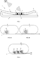
- FIG. 1 shows an example of an energy chain 1, the upper run 2 slides on the lower run 3. Relative to a fixed point 6 of the energy chain 1, from which a movable unit arranged on the driver 5 which can be moved back and forth, Module, or the like. (Not shown) is to be supplied, depending on the application and dimensioning, a critical chain section 14 or possibly several such sections results.
- Critical chain sections 14 can be determined empirically or can be seen by the person skilled in the art during planning, for example from the loading weight, the minimum bending radius in the deflection bend 4, the total length of the energy chain 1, the speed of the driver 5 and other application-dependent data.
- the chain section 14 of the upper run 2 can be critical, which, depending on the position of the reciprocating driver 5 or deflection bend 4, predominantly slides on the lower run and is therefore subject to most friction-related abrasion.
- the chain links 7 are in any case particularly susceptible to wear.
- radio circuits 10 are shown in more detail FIG.2A-2B , also FIG. 3 , FIG. 6-8 and FIG.11-12 evident.
- the radio circuits 10 can in particular have RFID transponders and communicate wirelessly with a suitable radio transceiver, in particular an RFID reader 12.
- the radio circuits 10 are arranged in critical areas 11 of the side plates 8 of the individual chain links 7 such that when one is reached predetermined, critical wear limit W ( FIG.2B ) changes the radio behavior of the radio circuit 10.
- the radio circuit 10 can send a different response signal to the RFID reader 12 than in the uncritical operating state or in the new state ( FIG.2A ).
- the predetermined wear limit W is set so that at their reaching or exceeding the energy chain 1 still withstands a relatively small number of movement cycles, for example approx. 1% of the total life expectancy. Only then can there be a high risk of failure.
- the wear limit W also depends on the application and can be determined by long-term trials on test setups, model calculations and / or empirical values.
- FIG. 3 For example, several independent radio circuits 10 can be provided on a single link plate 8 of a chain link 7.
- the individual radio circuits 10 change their radio behavior in succession in accordance with the progressive wear.
- a discrete, critical wear limit W cf. FIG.2B
- an approximate knowledge of the state of wear of a specific chain link 7 can also be made by radio or wireless means using the RFID reader 12.
- a plausibility check is made possible: if, for example, only a subordinate radio circuit 10 changes its behavior without the previous step having already signaled this, there is likely to be a non-wear-related error that must be checked during regular maintenance.
- FIG. 3 Identification of the individual radio circuit is necessary for the purpose of assignment to the wear level exceeded.
- the functions are made possible after FIG. 3 Particularly simple with RFID transponders that have a unique identifier or unique identification number and send back on radio request by the RFID reader 12.
- so-called RFID tags with a microchip are suitable, which are designed according to ISO 18000-1 or IEC 18000-6C, for example, and are unique Send identification information back to the RFID reader 12.
- the predetermined assignment is stored in the RFID reader 12 or a computer connected to it.
- FIG. 4-5 show an alternative arrangement of an energy chain 1 with electrotechnical wear detection according to a further embodiment.
- the energy chain 1 according to FIG. 4 is designed as a self-supporting chain (the upper run 2 does not slide on the lower run 3).
- such chains can also fail, for example if the life expectancy of the energy chain 1 is exceeded.
- Typical signs of wear and tear are fine, progressive cracks 15 in the side plates 8 of the chain links 7, which could ultimately lead to a complete breakage of a chain link 7.
- a critical chain section 14 can be determined empirically, in which the individual chain links 7 are most susceptible to signs of wear or the risk of chain breakage is greatest.
- FIG. 4 Correspondingly lies for the application FIG. 4 the critical area 11, where experience has shown that cracks due to material fatigue in the side flap 8 are most likely to occur.
- a radio circuit 10 is provided in the critical area 11, the transmission behavior of which changes in cooperation with, for example, an RFID reader 12 when cracks occur in the side plate 8.
- a large-area and permanent connection of the radio circuit 10 with the material of the side flap 8 is advantageous, which can be achieved particularly easily by means of self-adhesive RFID adhesive labels.
- this application does not require a break-resistant or durable substrate for the adhesive label. Rather, at least in the critical area 11, a breakable carrier material for the radio circuit 10 is desirable, the critical area 11 possibly being provided separately from the actual transponder or the carrier material overall being susceptible to breakage.
- FIG.1 and FIG.2A-2B or. FIG.1 and FIG.3 such as FIG. 4-5 are the radio circuits 10 themselves arranged directly in a critical area 11 of at least one chain link 7, preferably a plurality of chain links 7 in a critical chain section 14 of the energy chain 1.
- the critical chain section (s) 14 are determined empirically, for example by long-term tests in a test laboratory, and represent points of the energy chain 1 as a whole that are particularly susceptible to wear and / or fatigue.
- the principle for wireless wear detection on the basis of radio circuits 10 is applicable to the detection of wear or wear due to friction-related abrasion, through the operation of the energy chain 1, such as in the case of sliding energy chains 1 ( FIG. 1 ).
- the principle is equally applicable to the detection of cracks in the side plates 8 of selected chain links 7, which can occur if the nominal service life of the energy chain 1 is exceeded due to aging due to material fatigue or, if necessary, also before reaching life expectancy due to improper use.
- the radio circuit 10 changes its transmission behavior in cooperation with a transceiver, for example with the RFID reader 12, due to mechanical stress, but only when a condition of critical wear on the assigned chain link 7 is reached.
- the degree of wear at which the change detectable by the radio circuit 10 occurs is e.g. selected by positioning so that critical wear is signaled before the energy chain 1 breaks completely or fails.
- FIG. 6-8 show possible embodiments of radio circuits 610, 710, 810, especially for the application FIG. 1 , only their structure and function will be discussed below.
- the radio circuits 610, 710, 810 are designed as passive RFID transponders for wireless communication in the UHF frequency range of the IFM band.
- the RFID transponders 20 and 20A-20B include FIG. 6-8 each have a commercially available RFID microchip 21, shown schematically here as a resonator symbol, with a matching RFID antenna 22.
- the RFID microchip 21 has a memory with identification information and is supplied via the RFID antenna 22 by the transmission power of the RFID reader 12.
- the RFID transponder 20 or 20A-20B after FIG. 6-8 are passive and do not have their own energy source or separate power supply.
- the connections of the RFID microchip 21 to the RFID antenna 22 are bridged or "short-circuited" by means of a detector line 24, ie in any case they are incorrectly matched in terms of impedance.
- a line section 26 of the detector line 24 is guided as a conductor loop in the critical region 11 in such a way that it breaks as a detector element 26 when the wear limit is exceeded, ie the detector line 24 is interrupted.
- the proper supply of the RFID microchip 21 using the RFID antenna 22 is only released when the critical wear limit W is exceeded.
- the RFID transponder 20 of the radio circuit 610 only becomes ready to send when the wear limit W to be recognized has been reached or exceeded.
- the detector line 24 can be provided with a low-resistance shunt resistor 28.
- the actual RFID transponder 20, as well as the detector line 24 with its components, can be attached as a detection module to the same carrier 23, for example a fragile adhesive label, or can be cast into a brittle, break-sensitive material, for example.
- FIG. 7 is a further development of the principle FIG. 6 and comprises two RFID transponders 20; 20A.
- the transponder 20A functions according to the opposite principle compared to the transponder 20. With the transponder 20A, the supply of the RFID microchip 21 is not released in the event of a breakage of the detector element 26 on the detector line 24, but interrupted.
- the RFID transponder 20 is in turn identical to the transponder 20 FIG. 6 built up.
- FIG. 7 can - similar to in FIG. 3 -
- the detector element 26 of one transponder 20A, in comparison to the detector element 26 of the other transponder 20, is staggered with respect to the wear limit W in order to obtain additional information on wear and / or control.
- FIG. 8 shows a further embodiment with two RFID transponders 20; 20B, wherein a test transponder 20B is provided as a permanent test only for control purposes, and its transmission behavior does not change depending on wear or wear.
- the other RFID transponder 20 is identical or in principle the same as the transponder 20 according to FIG. 6-7 executed.
- FIG. 8 can - similar to in FIG. 3 -
- the test transponder 20B with part of its antenna arranged as a predetermined breaking point in the critical area 11, so that a further wear limit can be detected, for example for an emergency stop.
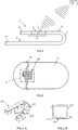
- FIG.9A-9B show a possibility for the protected arrangement of a radio circuit 10 in the side plate 90 of a multi-part chain link 7. Only the differences relevant to the previously known construction of the side plate 90 are discussed.
- the recess 92 is provided in the critical area 11 of the side plate 90, for example on the abrasion-prone, the deflection axis facing narrow side of the link plate 90.
- the cutout 92 is closed by means of a suitable closure element 94.
- the closure element 94 is held in a form-fitting manner and under pretension by the oblique side walls 93 of the recess 92, so that the position of the radio circuit 10 is fixed in an unchangeable manner.
- a radio circuit 10 in a break-prone housing can be used in a reliable manner as a detection module.
- the radio circuit can also be integrated in the closure element 94.
- the cutouts 92 can remain open or can be closed with further closure elements in order to avoid interference edges.
- FIG. 10 shows a further embodiment of the arrangement of radio circuits 10 based on a schematic cross section of a chain link 7.
- the two side plates 8 of the chain link 7 are connected to one another via transverse webs 9 and thus form the interior for receiving the guided lines.
- retrofittable sliding shoes 100 are attached as detection modules in which the radio circuit 10 (not shown in FIG. 10 ) is cast in, for example in the IMKS process (integrated metal plastic injection molding) or in multi-component injection molding, or is firmly bonded by gluing.
- IMKS process integrated metal plastic injection molding
- the design according to FIG. 10 enables the retrofitting of energy guiding chains 1 as required, depending on the position of the critical chain sections 14 and the construction of the wear detection according to the invention in a modular principle, without impairing the actual design of the chain links 7.
- Suitable systems and methods for radio-based detection of transponders are known to the person skilled in the art from the specialist literature and relevant standards (e.g. ISO 18000-1 or IEC 18000-6C or the like) and are therefore not explained in more detail.
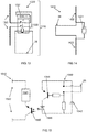
- FIG.11 shows a particularly simple radio circuit in the form of an RF transponder 120, an LC resonant circuit known for goods security (EAS: electronic article surveillance), for example, being modified by a detector line 24 which forms a loop in the critical area 11, which acts as a detector element 26 serves.
- EAS electronic article surveillance
- the resonant circuit from the RF induction antenna 122 and RF capacitor 125 withdraws from an external one electromagnetic RF field, which is tuned to its resonance frequency - typically around 8.2 MHz - transmission energy and is thus detectable.
- the detector element 26 breaks the connection between the RF induction antenna 122 and the RF capacitor 125 when the wear exceeds the wear limit W.
- the resonant circuit thus becomes ineffective and the RF transponder 120 can no longer be detected at the resonance frequency.
- carrier 23 in particular, a custom-made adhesive label can be considered, which includes a critical area 11, which is prone to breakage, as a substrate for the conductor loop forming detector element 26.
- the other features of the RF transponder 120 can be from the teaching US 3,810,147 or US 3,500,373 correspond.
- the particularly inexpensive construction FIG.11 is particularly advantageous for very large quantities.
- FIG.12 shows a further development of the RFID circuits FIG. 6-8 , in that the radio circuit 1210 after FIG.12 is ready for operation in new condition, is not ready for operation when a first wear limit W1 is exceeded and becomes operational again when a second wear limit W2 is exceeded.
- a conductor with a parallel connection of an interference capacitor C2 and an interference coil L2 is connected to the detector line.
- a conductor loop acts in series with the interference capacitor C2, which decouples the interference capacitor C2 when the wear exceeds the first wear limit W1, acts as the first detector element 1226.
- the interference coil itself which is destroyed by abrasion on the wear limit W2, acts as the second detector element 1227.
- the parallel connection of the interference capacitor C2 After the parallel connection of the interference capacitor C2 has been disconnected, only the interference coil L2 acts. Their impedance is selected so that the resonance circuit is detuned with the resonance capacitor C1 and the resonance coil (antenna) L1 serving as an antenna and no longer in the frequency range of the reading device ( FIG. 1 ) responds resonantly.
- the RFID transponder 1220 is therefore inoperable with respect to the reader.
- a multi-stage staggered detector arrangement as in FIG. 3 or FIG.12 has the advantage that the system allows a functional test at the beginning and, above all, can be configured fully automatically by automatically recording the identification information of all existing radio circuits 1210. If there is no return of previously recorded identification information in later operation, it must be concluded that a wear limit has been exceeded.
- FIG.12 has the further advantage that - without multiplication of the radio circuits 1210 - supercritical wear can be reliably assumed if the identification information concerned is detected again after a certain time interval.
- An emergency stop is preferably triggered because the worn cable routing has not yet been renewed or repaired.
- FIG.13-FIG.15 show further embodiments of radio circuits 1310; 1410; 1510 for RFID ICs with dipole antennas for the UHF frequency range, e.g. according to ISO 18000-6C.
- these offer a greater range than LF or RF radio circuits (e.g. according to FIG. 6-8 or FIG.11 ) and can also be inexpensively manufactured as passive detection modules.
- the mode of operation and arrangement on the cable routing corresponds, for example, to one of the examples above.
- a dipole antenna 1322 can be switched via a special IC 1330 (integrated circuit), for example an ASIC, in such a way that it can be galvanically isolated from or connected to the RFID circuit 1321 in the manner of a switching relay.
- the IC 1330 has a transistor arrangement which connects both nodes of the dipole antenna 1322 when a conductor loop used as a detector element 1326 is cut.
- the detector element 1326 is connected to terminals of the IC 1330 which control the relay-like transistor arrangement.
- the RFID circuit 1321 can be designed as an integrated component of the IC 1330.
- the Radio circuit 1310 can be active, ie can be connected to a supply, or can also be supplied passively via the dipole antenna 1322 from the radio power.
- FIG. 14 is a dipole antenna 1422 bridged with a conductor loop used as detector element 26.
- the performance parameters of the dipole antenna 1422 are influenced in a measurable manner, so that the detector element 26 is separated due to wear using a suitable reading device (cf. FIG. 1 or. FIG. 4 ) is recognizable.
- a suitable reading device cf. FIG. 1 or. FIG. 4
- a "short circuit" (unlike an induction antenna) FIG. 6 ) not necessarily to the failure of the radio signal, but to a demonstrable parameter change in the radio behavior that the RFID chip 1421 causes with the dipole antenna 1422.
- the radio circuit 1410 after FIG. 13 is suitable as a purely passive system.
- a dipole antenna 1522 is also connected to an RFID chip 1521.
- An active detector circuit 1540 with a voltage source 1542 also comprises, as detector element 26, a conductor loop that can be separated by wear for arrangement in a wear-critical area.
- the pnp transistor 1544 switches to pass, so that the LED 1546 generates light and, in the manner of an optocoupler, switches the NPN photo transistor 1550, so that the dipole antenna 1522 is connected to both connections of the RFID chip 1521 with a low resistance .
- a conventional optocoupler can also be used for this.
- the detector circuit 1540 thus enables the connection of the dipole antenna 1522 to the RFID chip 1521, ie the RFID chip 1521 is ready for operation.
- the radio circuit 1510 is suitable as an active system, the voltage source 1542 also being able to supply the RFID chip 1521 (not shown).
- RFID transponders with IC and information memory are different from 1-bit transponders (cf. FIG.11 ) enable more intelligent systems which, among other things, allow the affected energy chain 1 to be determined in more complex systems, a closer localization of the worn chain link, and for example also the use of several detector elements on an RFID chip (not shown), for example for more reliable detection.
- FIG. 16-18 show a further development of the principle FIG. 6-8 .
- a higher level of recognition reliability can be achieved by concluding that the correct signal from a first RFID transponder is received and the signal from a second RFID transponder is not operational, without excessive wear.
- FIG. 16-18 show three further embodiments of radio circuits 1610; 1710; 1810, which differ from the preceding examples in particular in that the transponder in each exemplary embodiment has two RFID chips 1621A, 1621B, both of which are connected 1622; 1722; Are 1822.
- the radio circuits 1610; 1710; 1810 is in new condition and up to critical wear, e.g. if the wear limit W is exceeded, initially only the first 1621A RFID chip is ready to receive and transmit. Only when the detector element 1626 due to excessive wear, e.g. due to mechanical abrasion beyond the wear limit W, separated or removed, the second RFID chip 1621B is also practically ready to receive and transmit.
- the RFID chips 1621A, 1621B can be of the same type, but the identifications or identification information of the RFID chips 1621A, 1621B differ from one another.
- the first RFID chip 1621A thus initially allows the radio circuits 1610; 1710; 1810 e.g. as to whether the wear detection is provided and / or ready for operation.
- This check is based on the previously known identifier of the first RFID chip 1621A. This is received by the reader and is e.g. stored in a database. This first identifier can also be used otherwise, e.g. for logistic purposes or for a recognition of the system configuration.
- the first RFID chip 1621A can be conductive (galvanic) or inductive with antenna 1622; 1722 and 1822 respectively.
- the radio circuits 1610; 1710 or 1810 can be implemented in particular as a PCB or as an FPC, the antennas 1622; 1722 and 1822 are designed as conductor tracks.
- the RFID chips 1621A, 1621B used are preferably of identical construction, for example suitable commercially available integrated circuits (ICs), preferably using SMD or SMT technology.
- the second RFID chip 1621B is in FIG. 16-18 via a transmission line 1623 with the common antenna 1622; Conductively connected in 1722 and 1822.
- a blind line or stub 1627 is connected in parallel to the transmission line 1623.
- the stub line 1627 serves as a detector line and in the example shown is designed as a two-wire line, for example similar to a so-called "single shunt stub tuner", and is short-circuited via a conductor section located in the critical region 11 (KS stub line). This conductor section in the critical area 11 forms the detector element 1626, as in FIG FIG. 16-18 shown.
- the stub line 1627 can alternatively be open or idling (LL stub line not shown), but with conductor sections exposed in the critical region 11, which are separated in the event of excessive wear beyond the wear limit W, and thereby serve as a detector element 1626.
- LL stub line not shown
- FIG. 16-18 the construction according FIG. 16-18 is simple to implement, there is also, for example, a double stub line (analogous to the so-called “double shunt stub tuner”) or a pronounced adaptation network within the scope of the invention, for example in order to minimize any interference with the first RFID chip 1621A.
- the conductor track dimensions of the section which forms the detector element 1626 and the conductor track dimensions of the conductor track sections of the stub line 1627 remaining after excessive wear are set in a predetermined ratio.
- the setting is made such that in the new state, a sufficient mismatch, in particular impedance mismatch, disturbs the readiness to receive and transmit of the second RFID chip 1621B to such an extent that it cannot communicate effectively with the reading device.
- the stub 1627 with the detector element 1626 can deliberately deteriorate the passive supply and / or transmission power of the RFID chip 1621B to a sufficient degree.
- the relationship can also do so be set so that after detaching the detector element 1626 a sufficient adaptation, in particular impedance adaptation, of the transmission line 1623, which the antenna 1622; 1722 or 1822 connects to the second RFID chip 1621B.
- the stub line 1627 can in particular lead to extensive line matching or impedance matching with respect to the additional transmission line 1623 on the second RFID chip 1621B.
- the position of the connection point of the branch line 1627 on the transmission line 1623 itself can also be set in accordance with these specifications.
- the deterioration-dependent change in impedance-matching is carried out in relation to the additional transmission line 1623 between antenna 1622; 1722; 1822 and the second RFID chip 1621B.
- the absolute line lengths of stub line 1627 and detector element 1626 can be set over a certain range because the conditions are repeated periodically with half the operating wavelength ( ⁇ ).
- An extension by n * ⁇ / 2 (with n integer) is possible with essentially the same behavior.
- the reflection at the connection point of the stub line 1627 with respect to the first RFID chip 1621A can be adjusted in such a way that the total length of the transmission line 1623 and the position of its connection point to the stub line 1627 are suitably selected the transmission behavior of the first RFID chip 1621A is not significantly affected by the wear-related change in state, so that, for example, the range or transmission power of the first RFID chip 1621A changes only insignificantly when new and in the critical state of wear. Regardless of this (analogous to the principle according to FIG. 7 ) it can alternatively be provided that, in the event of critical wear, the second RFID chip 1621B becomes ready to receive and transmit, and the first RFID chip 1621A practically fails, which likewise allows a function check in the uncritical state.
- the second RFID chip 1621B is ready to receive and transmit because of the adaptation that occurs, due to the elimination of the fault or mismatch due to the detector element 1626 receive further identification of the second RFID chip 1621B, which enables conclusions to be drawn about critical wear.
- the previously known identifier of the second RFID chip 1621B can also be stored, for example stored in a database.
- the detector element 1626 is spatially separated from the RFID chips 1621A, 1621B and the common antenna 1610; 1710 or 1810 separate area, e.g. on one of the antennas 1610; 1710 or 1810 opposite end of the PCB or FCB and possibly arranged on the back.
- the embodiments according to FIG. 16-18 are particularly suitable for transponders or RFID chips 1621A, 1621B in the high-frequency range, for example at UHF, in particular for UHF-RFID, for example with a basic frequency of 865MHz to 955MHz or 2.4 GHz (with wavelengths in the decimeter range).
- the principle of the wear-related change in line adaptation at the fundamental frequency as the detection principle is analogous to an exemplary embodiment FIG. 6-8 transferable. With idling or short-circuited stub lines of a suitably selected length, inductive or capacitive reactances can basically be set from zero to infinity.
- the impedance mismatch or the optional adaptation is carried out in particular by the appropriate setting of the reactance using the detector line, for example by the short-circuit stub 1627.
- the dimensioning of the conductor track dimensions of the detector element 1626 and the stub 1627 and the determination of the connection point can be done, for example, using the Smith diagram in a manner known per se.
- the radio circuits 1610; 1710; 1810 after FIG. 16-18 differ from each other by the type of antenna used.
- the radio circuit 1610 in FIG. 16 has a loop dipole antenna 1622
- the radio circuit 1710 in FIG. 17 has a dipole antenna 1722.
- the latter offer a space-saving design.
- the radio circuit 1810 in FIG. 18 has an antenna coil 1822 for possibly longer range.
- the antennas 1622; 1722; 1822 are dimensioned to match the selected fundamental frequency or the selected RFID chips 1621A, 1621B.
- matching circuits with discrete components can also be considered, for example an L-type, n-type, P-type impedance matching network.
- the detector line with the detector element 1626 can also filter out the radio frequency (HF) signals in the operating band of the RFID chips 1621A, 1621B as a separating or filter circuit.
- HF radio frequency
- RFID transponders with IC and information storage unlike 1-bit transponders (cf. FIG. 9 ), enable more intelligent systems that allow, among other things, a determination of the component or components concerned in more complex systems, for example a closer localization of the worn plastic part and for example also the use of several detector elements on an RFID chip (not shown), for example for more reliable detection. Also the functional test, e.g. after FIG. 16-18 , is made possible by clearly assignable identification information.
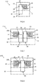
- FIG.19A-19B show a detection module 190 for the initial equipping or retrofitting of energy chains 1 of a known type.
- the detection module 190 has a plastic housing 191 which is produced in one piece as an injection molded part and has a plate-like, flat receptacle 192 for a common RFID transponder.
- the transponder is inserted into the receptacle 192 through an opening slot on the end and is then secured to the housing 191, for example by casting or gluing.
- the housing 191 has a first male connector 193A and a longitudinally opposite second female connector 193B.
- the first connector 193A is structurally identical to the mounting horn, which is typically molded onto the side plates 8 of the chain links 7 for the releasable attachment of the cross bar 9 or opening bar, ie has a positive shape matching the corresponding connector receptacle on the cross bar 9.
- the second connector 193B is identical in construction to the connector receptacle on the crosspiece 9, that is to say it has a negative shape which matches the fastening horn of the side plate 8.
- the recognition module 190 can be mounted in place of a typical crosspiece 9, possibly using a shorter crosspiece as an extension piece, such as FIG.19B shows.
- the position of the receptacle 192 is offset to the outside by a predetermined amount in the height direction of the side straps 8, so that the radio circuit (not shown here) lies at the desired wear limit W to be recognized.
- FIG.20A-20D show as a further development of the invention a recognition module 200, which is also particularly well suited for retrofitting or initial equipping chain links 7 of a known energy chain 1.
- the detection module 200 has a housing 291 made of plastic with a flat, plate-like main part 293 and a head 294 projecting transversely to its main plane.
- the main part 293 can be opened via a hinged lid 295 by means of a film hinge 296 in order to insert the radio circuit 10 into a corresponding receptacle 292 of the housing 291 to bring.
- the housing 291 has a latching tongue 298 for latching into a recess 299 in the crosspiece 9, which passes through in the longitudinal direction of the energy chain 1.
- Such recesses 299 are typically provided in a grid-like manner in order to mount known separating webs (not shown) for dividing up the interior at conventional intervals on conventional transverse webs 9. These recesses 299 can be used to fasten the detection module 200. Accordingly, the closed main part 293 to the recess 299 of the cross bar 9 is designed as a plug-in tab or tongue, and can FIG20C-20D illustrate, so easy to install.
- the latching tongue 298 latches with the crosspiece 9 in order to secure the detection module 200 thereon.
- the radio circuit 10 in FIG.20A-20D has a particularly preferred two-part construction, with a first circuit part 10A and a flexible second circuit part 10B.
- first circuit part 10A at least the integrated circuit or the microchip of the RFID transponder (see above) is provided as a conventional circuit on a rigid substrate or carrier.
- the second circuit part 10B is designed to be flexible, for example as an FCB, "flexprint", film circuit or the like.
- the second circuit part 10B comprises the detector element 26 according to the invention in a spatial area that is spaced apart from the first circuit part 10A, transversely offset from its main plane, and the detector line to the first circuit part 10A.
- a recess 297 is provided, by means of which the detector element 26 can be positioned and fastened, for example cast or glued, in the second circuit part 10B, so that its spatial position predetermines the wear limit W to be detected.
- the dimensioning, in particular the overall height of the head 294, allows the position of the detector element 26 and thus also the wear limit W relative to the nominal position of the crosspiece 9 to be optionally defined.
- the flexible circuit part 10B enables the detached, projecting positioning of the detector element 26.
- the area of the head 294 with the detector element 26 is exposed to wear and serves as a type of predetermined breaking point.
- the detection module 200 thus has a mechanical connector which interacts with a counterpart of the energy guide chain which is known per se, for example the recess 299 for fastening separating webs (not shown) to the crossbar 9.
- Detection modules 190, 200 according to FIG. 19-20 allow the simple and targeted equipping of a dynamic cable routing 1 with the functionality of an electrotechnical wear detection in critical longitudinal sections 14.
- the housing 192, 292 of the detection modules 190, 200 is preferably made of a less wear-resistant, in particular softer plastic than the side plates 8 of the chain links 7.
- FIG.21A-21B show as an alternative to the construction FIG. 1-4 , a dynamic line routing unit 211, which is assembled in sections in the longitudinal direction from a number of several segments 217 made in one piece.
- the adjacent segments 217 are each flexibly connected to one another in the longitudinal direction by a film hinge 219.
- the design of the line routing unit 211 is known per se, for example from WO 2005/040659 A1 .
- a radio circuit 210 is also provided for the detection of wear in a critical area 11 of those segments 217 which are particularly susceptible to wear and / or fatigue fracture.
- the radio circuit 210 is attached in the form of a self-adhesive RFID tag to the segments 217 selected radially on the inside in the deflection bend.
- the radio circuit 210 will also wear and thus become ineffective.
- the antenna itself can represent the detector element and an inexpensive RFID tag can be used.
- FIG. 10 1 energy chain 7 chain link 2 upper run 8 side tab 3 lower run 9 crossbars 4 deflection bends 100 sliding shoe 5 drivers 6 benchmark FIG.11 7 chain link 11 critical area 8 side tab 24 detector line 10 radio circuit 26 detector element 11 critical area 120 RF transponders 12 RFID reader 122 RF induction antenna 14 critical chain section 125 RF capacitor 15 tab break or 23 carriers Tab tear W wear limit (Material fatigue) W wear limit FIG.12 24 detector line FIG.
- FIG.20A-20D 26 detector element 10 radio circuit 1410 radio circuit 10A first circuit part 1421 RFID chip 10B second circuit part 1422 dipole antenna 26 detector element 200 detection module FIG. 15 291 housing 26 detector element 292 recording 1510 radio circuit 293 body 1521 RFID chip 294 head 1522 dipole antenna 295 hinged lid 1540 detector circuit 296 film hinge 1542 voltage source 297 recess 1544 transistor (PNP) 298 latch 1546 LED 299 recess (in crosspiece 9) 1550 photo transistor (NPN) FIG.
- FIG.21A-21B 11 critical area 11 critical area 1610; 1710; 1810 211 cable routing unit
- Radio circuit 210 RFID tag 1621A RFID chip 217 segment 1621B RFID chip 219 film hinge 1622; 1722; 1822 antenna W wear limit 1623 transmission line 1626 detector element 1627 branch line W wear limit FIG.19A-19B
- detection module 191 housing 192 recording 193A male connector 193B female connector
Landscapes
- Engineering & Computer Science (AREA)
- General Engineering & Computer Science (AREA)
- Physics & Mathematics (AREA)
- Mechanical Engineering (AREA)
- Civil Engineering (AREA)
- Structural Engineering (AREA)
- Architecture (AREA)
- General Physics & Mathematics (AREA)
- Electromagnetism (AREA)
- Computer Security & Cryptography (AREA)
- Automation & Control Theory (AREA)
- Signal Processing (AREA)
- Investigating Or Analyzing Materials By The Use Of Electric Means (AREA)
- Train Traffic Observation, Control, And Security (AREA)
- Radar Systems Or Details Thereof (AREA)
- Near-Field Transmission Systems (AREA)
- Control Of Conveyors (AREA)
- Pipeline Systems (AREA)
- Details Of Indoor Wiring (AREA)
- Electric Cable Arrangement Between Relatively Moving Parts (AREA)
- Measurement Of Length, Angles, Or The Like Using Electric Or Magnetic Means (AREA)
- Devices For Conveying Motion By Means Of Endless Flexible Members (AREA)
Applications Claiming Priority (3)
| Application Number | Priority Date | Filing Date | Title |
|---|---|---|---|
| DE202016000501.5U DE202016000501U1 (de) | 2016-01-28 | 2016-01-28 | Energieführungskette oder Leitungsführungseinrichtung mit elektrotechnischer Verschleißerkennung |
| DE202016102134.0U DE202016102134U1 (de) | 2016-04-21 | 2016-04-21 | Funkschaltung, insbesondere zur Verschleißerkennung |
| PCT/EP2017/051870 WO2017129805A1 (de) | 2016-01-28 | 2017-01-27 | LEITUNGSFÜHRUNGSEINRICHTUNG MIT ELEKTROTECHNISCHER VERSCHLEIßERKENNUNG UND FUNKSCHALTUNG HIERFÜR |
Publications (2)
| Publication Number | Publication Date |
|---|---|
| EP3408561A1 EP3408561A1 (de) | 2018-12-05 |
| EP3408561B1 true EP3408561B1 (de) | 2020-07-15 |
Family
ID=57909632
Family Applications (1)
| Application Number | Title | Priority Date | Filing Date |
|---|---|---|---|
| EP17701876.9A Active EP3408561B1 (de) | 2016-01-28 | 2017-01-27 | Leitungsfuehrungseinrichtung mit elektrotechnischer verschleisserkennung und funkschaltung hierfuer |
Country Status (14)
| Country | Link |
|---|---|
| US (1) | US11143270B2 (ko) |
| EP (1) | EP3408561B1 (ko) |
| JP (1) | JP7026623B2 (ko) |
| KR (1) | KR102395597B1 (ko) |
| CN (1) | CN109477550B (ko) |
| AU (1) | AU2017213158B2 (ko) |
| BR (1) | BR112018015120B1 (ko) |
| CA (1) | CA3011651C (ko) |
| ES (1) | ES2822342T3 (ko) |
| MX (1) | MX2018008997A (ko) |
| MY (1) | MY193561A (ko) |
| SG (1) | SG11201806414UA (ko) |
| TW (1) | TWI750150B (ko) |
| WO (1) | WO2017129805A1 (ko) |
Cited By (2)
| Publication number | Priority date | Publication date | Assignee | Title |
|---|---|---|---|---|
| EP3971445A1 (de) * | 2016-12-23 | 2022-03-23 | igus GmbH | Systeme zur überwachung des betriebs einer energieführungskette |
| EP4025807B1 (de) | 2019-09-02 | 2023-05-31 | Tsubaki Kabelschlepp GmbH | Vorrichtung umfassend eine energieführungskette und eine gleitauflage |
Families Citing this family (13)
| Publication number | Priority date | Publication date | Assignee | Title |
|---|---|---|---|---|
| DE202014104075U1 (de) * | 2014-09-01 | 2014-09-09 | Igus Gmbh | Leitungsführungseinrichtung |
| EP3615842B1 (de) * | 2017-04-24 | 2021-04-14 | Igus GmbH | System zur leitungsüberwachung in einer energieführungskette |
| JP6886369B2 (ja) * | 2017-08-29 | 2021-06-16 | 川崎重工業株式会社 | 鉄道車両の制輪子摩耗検知ユニット及びそのセット |
| DE202018100339U1 (de) * | 2018-01-22 | 2019-04-24 | Tsubaki Kabelschlepp GmbH | Energieführungsvorrichtung mit einem Verschleißdetektor |
| DE202018100962U1 (de) * | 2018-02-21 | 2018-03-02 | Igus Gmbh | Überwachungssystem für Energieführungsketten |
| DE202018102144U1 (de) * | 2018-04-18 | 2019-05-27 | Igus Gmbh | Energieführungskette mit Dämpfungselementen sowie Seitenteil dafür |
| DE202018102239U1 (de) * | 2018-04-21 | 2019-05-23 | Igus Gmbh | Energieführungskette mit Verschleißerkennung |
| DE202019101608U1 (de) * | 2019-03-20 | 2019-09-23 | Igus Gmbh | Systeme zur Positionsbestimmung mit einer Energieführungskette |
| CN110943426A (zh) * | 2019-12-19 | 2020-03-31 | 深圳市沃尔电力技术有限公司 | 智能型电缆附件 |
| DE202020100143U1 (de) | 2020-01-10 | 2020-02-24 | Igus Gmbh | Kunststoff-Bauteile für Energieführungsketten mit integrierter Sensorik |
| DE102022128793A1 (de) | 2022-04-25 | 2023-10-26 | Igus Gmbh | Verfahren und System zur indirekten Erkennung von Verschleiß einer gleitenden Energieführungskette |
| TW202407233A (zh) | 2022-04-25 | 2024-02-16 | 德商易格斯股份有限公司 | 用於間接偵測拖鏈中之磨損的方法和系統 |
| DE102022109963A1 (de) | 2022-04-25 | 2023-10-26 | Igus Gmbh | Verfahren und System zur indirekten Erkennung von Verschleiß einer Leitungsführungseinrichtung bzw. Energieführungskette |
Family Cites Families (36)
| Publication number | Priority date | Publication date | Assignee | Title |
|---|---|---|---|---|
| DE1444264U (ko) | ||||
| US3500373A (en) | 1966-05-06 | 1970-03-10 | Nat Bank Of North America The | Method and apparatus for article theft detection |
| US3473769A (en) | 1967-01-06 | 1969-10-21 | Ibm | Retainer for flexible leads |
| US3634845A (en) | 1968-03-27 | 1972-01-11 | Gen Alarm Corp | Window security system |
| US3810147A (en) | 1971-12-30 | 1974-05-07 | G Lichtblau | Electronic security system |
| US4578941A (en) | 1984-08-27 | 1986-04-01 | Emerson Electric Co. | Load carrying device |
| DE3531066A1 (de) | 1985-08-30 | 1987-03-12 | Igus Gmbh | Energiezufuehrungskette |
| DE4444264C2 (de) * | 1994-12-13 | 2002-05-08 | Continental Ag | Verfahren und Anordnung zur Überwachung eines Fördergurtes |
| DE19541928C1 (de) * | 1995-11-10 | 1997-06-12 | Igus Gmbh | Energieführungskette |
| DE19647322A1 (de) | 1996-11-15 | 1998-05-20 | Kabelschlepp Gmbh | Kettenglied aus verschiedenen Werkstoffen und Verfahren zu dessen Herstellung |
| DE19710489A1 (de) * | 1997-03-13 | 1998-09-24 | Kabelschlepp Gmbh | Faltbares Schutzelement für Leitungen |
| US5969260A (en) | 1998-03-30 | 1999-10-19 | Mcdonnell Douglas Corporation | Remotely interrogatable apparatus and method for detecting defects in structural members |
| US6107921A (en) * | 1998-04-16 | 2000-08-22 | Motorola, Inc. | Conveyor bed with openings for capacitive coupled readers |
| DE19860948C2 (de) | 1998-12-31 | 2002-02-14 | Igus Gmbh | Leitungsführungseinrichtung |
| DE20107003U1 (de) | 2001-04-23 | 2002-09-19 | Igus Spritzgußteile für die Industrie GmbH, 51147 Köln | Energieführungskette |
| DE10206676A1 (de) | 2002-02-18 | 2003-08-28 | Giesecke & Devrient Gmbh | Mit einem Transponder betätigbare Schaltvorrichtung |
| DE20305678U1 (de) * | 2003-04-07 | 2003-07-24 | Igus Spritzgußteile für die Industrie GmbH, 51147 Köln | Überwachungssystem für Energieführungskette |
| EP1611368B1 (de) | 2003-04-04 | 2008-11-19 | igus GmbH | Überwachungssystem für den betrieb wenigstens einer energieführungskette |
| WO2004099795A2 (en) | 2003-04-30 | 2004-11-18 | United Stated Of America As Represented By The Administrator Of The National Aeronautics And Space Administration | Magnetic field response measurement acquisition system |
| DE10346486B4 (de) | 2003-10-02 | 2012-08-02 | Murrplastik Systemtechnik Gmbh | Energieführungskette |
| US7718894B2 (en) | 2003-10-15 | 2010-05-18 | Igus Gmbh | Line guide device |
| BE1016120A6 (nl) | 2004-07-14 | 2006-03-07 | Picanol Nv | Werkwijze en inrichting voor het bepalen van de sleet van een grijperdrager en grijperdrager. |
| JP4476187B2 (ja) | 2005-07-01 | 2010-06-09 | 株式会社椿本チエイン | ケーブル類保護案内装置 |
| GB0515176D0 (en) | 2005-07-23 | 2005-08-31 | Renold Plc | Transmission chain monitoring system |
| DE102007034167A1 (de) | 2007-07-23 | 2009-01-29 | Alois Pöttinger Maschinenfabrik Gmbh | Landmaschine |
| JP4847935B2 (ja) * | 2007-08-29 | 2011-12-28 | 八千代工業株式会社 | ケーブル保護チェーンの破損検知システムおよび破損検知方法 |
| JP2009063532A (ja) | 2007-09-10 | 2009-03-26 | Ihi Corp | 亀裂検出装置 |
| DE202008001415U1 (de) * | 2008-01-31 | 2009-06-04 | Kabelschlepp Gmbh | System mit Sicherheitsabschaltung |
| US8395521B2 (en) | 2009-02-06 | 2013-03-12 | University Of Dayton | Smart aerospace structures |
| US20120043980A1 (en) | 2009-02-27 | 2012-02-23 | Brian Investments Pty Ltd | Wear sensor |
| CN101504383B (zh) | 2009-03-24 | 2012-02-22 | 徐俊峰 | 皮带撕裂监测装置 |
| DE202012003907U1 (de) | 2012-04-19 | 2012-05-15 | Igus Gmbh | Überwachungssystem für Zug- und Druckkräfte in einer Energieführungskette und entsprechender Kraftaufnehmer |
| DE102012113082A1 (de) | 2012-12-24 | 2014-06-26 | Tsubaki Kabelschlepp GmbH | Energieführungsvorrichtung mit wenigstens einer Antriebseinrichtung für lange Verfahrwege |
| DE202013101604U1 (de) * | 2013-04-16 | 2013-05-07 | Igus Gmbh | Energieführungseinrichtung |
| DE202014100540U1 (de) * | 2014-02-07 | 2014-03-20 | Igus Gmbh | Energieführungskette und Überwachungssystem zum Schutz gegen Leitungsabriss |
| JP6651508B2 (ja) * | 2014-09-18 | 2020-02-19 | イグス ゲゼルシャフト ミット ベシュレンクター ハフトゥング | 特にクリーンルームでの応用のための配線案内装置、シェル部分及びシェル部分のための支持リブ構造 |
-
2017
- 2017-01-27 KR KR1020187024374A patent/KR102395597B1/ko active IP Right Grant
- 2017-01-27 MX MX2018008997A patent/MX2018008997A/es unknown
- 2017-01-27 JP JP2018538834A patent/JP7026623B2/ja active Active
- 2017-01-27 CA CA3011651A patent/CA3011651C/en active Active
- 2017-01-27 CN CN201780020391.5A patent/CN109477550B/zh active Active
- 2017-01-27 WO PCT/EP2017/051870 patent/WO2017129805A1/de active Application Filing
- 2017-01-27 BR BR112018015120-3A patent/BR112018015120B1/pt active IP Right Grant
- 2017-01-27 SG SG11201806414UA patent/SG11201806414UA/en unknown
- 2017-01-27 ES ES17701876T patent/ES2822342T3/es active Active
- 2017-01-27 AU AU2017213158A patent/AU2017213158B2/en active Active
- 2017-01-27 US US16/073,974 patent/US11143270B2/en active Active
- 2017-01-27 EP EP17701876.9A patent/EP3408561B1/de active Active
- 2017-01-27 MY MYPI2018702611A patent/MY193561A/en unknown
- 2017-02-02 TW TW106103407A patent/TWI750150B/zh active
Non-Patent Citations (1)
| Title |
|---|
| None * |
Cited By (3)
| Publication number | Priority date | Publication date | Assignee | Title |
|---|---|---|---|---|
| EP3971445A1 (de) * | 2016-12-23 | 2022-03-23 | igus GmbH | Systeme zur überwachung des betriebs einer energieführungskette |
| EP4025807B1 (de) | 2019-09-02 | 2023-05-31 | Tsubaki Kabelschlepp GmbH | Vorrichtung umfassend eine energieführungskette und eine gleitauflage |
| US12092187B2 (en) | 2019-09-02 | 2024-09-17 | Tsubaki Kabelschlepp GmbH | Device comprising an energy chain and a sliding table |
Also Published As
| Publication number | Publication date |
|---|---|
| EP3408561A1 (de) | 2018-12-05 |
| US11143270B2 (en) | 2021-10-12 |
| BR112018015120B1 (pt) | 2022-08-23 |
| KR20180103157A (ko) | 2018-09-18 |
| MY193561A (en) | 2022-10-19 |
| AU2017213158B2 (en) | 2020-07-30 |
| MX2018008997A (es) | 2018-11-19 |
| JP2019511679A (ja) | 2019-04-25 |
| WO2017129805A1 (de) | 2017-08-03 |
| KR102395597B1 (ko) | 2022-05-09 |
| CA3011651C (en) | 2022-07-19 |
| CN109477550A (zh) | 2019-03-15 |
| SG11201806414UA (en) | 2018-08-30 |
| ES2822342T3 (es) | 2021-04-30 |
| US20190040935A1 (en) | 2019-02-07 |
| CN109477550B (zh) | 2020-11-06 |
| JP7026623B2 (ja) | 2022-02-28 |
| AU2017213158A1 (en) | 2018-08-23 |
| BR112018015120A2 (pt) | 2018-12-18 |
| CA3011651A1 (en) | 2017-08-03 |
| TW201800683A (zh) | 2018-01-01 |
| TWI750150B (zh) | 2021-12-21 |
Similar Documents
| Publication | Publication Date | Title |
|---|---|---|
| EP3408561B1 (de) | Leitungsfuehrungseinrichtung mit elektrotechnischer verschleisserkennung und funkschaltung hierfuer | |
| EP3469224B1 (de) | Gleitlager, kunststoffgleitelement, system und verfahren zur verschleisserkennung | |
| DE202016000501U1 (de) | Energieführungskette oder Leitungsführungseinrichtung mit elektrotechnischer Verschleißerkennung | |
| DE602004009090T2 (de) | Siegel | |
| DE19840081B4 (de) | System und Verfahren zur Überwachung einer einem Verschleiß unterworfenen Schicht eines Gegenstandes, insbesondere der Deckschicht eines Fördergurtes | |
| DE4444264C1 (de) | Verfahren und Anordnung zur Überwachung eines Fördergurtes | |
| DE19525326C1 (de) | Verfahren und Anordnung zur Überwachung eines Fördergurtes | |
| WO2009106274A1 (de) | Vorrichtung zur überwachung der belagdicke eines bremsbelags einer reibungsbremse eines fahrzeugs | |
| EP1766118B1 (de) | Verfahren und vorrichtung zum automatischen überwachen eines greiferträgers und greiferträger | |
| EP3052276B1 (de) | Messer mit einem am erl angeordneten rfid-transponder | |
| EP0716992A2 (de) | Verfahren und Anordnung zur Überwachung eines Fördergurtes | |
| DE102012211188A1 (de) | Zustandsüberwachung mit RFID | |
| DE102010005714B4 (de) | Sicherheitsanhänger, Anordnung mit einem Sicherheitsanhänger und Verfahren zum Betreiben eines Sicherheitsanhängers | |
| DE202016102134U1 (de) | Funkschaltung, insbesondere zur Verschleißerkennung | |
| DE102007058277A1 (de) | Fahrzeuginsassen-Schutzvorrichtung | |
| DE102020118189B4 (de) | Gurtriss-Überwachungssystem | |
| WO2010124811A1 (de) | Magnetisch koppelnde nahfeld-rfid-antenne | |
| EP2036006B1 (de) | Chipkarte und verfahren zur herstellung einer chipkarte | |
| WO2014121790A1 (de) | Vorrichtung und verfahren zur feststellung eines betriebsgefährdenden zustandes eines bandförmigen lastträgers | |
| BE1027257B1 (de) | Förderbandanlage mit im Förderband integrierter Datenübertragung | |
| WO2024083894A1 (de) | Vorrichtung und verfahren zur strukturellen überwachung eines objekts | |
| DE10228232C1 (de) | Betätiger für einen Sicherheitsschalter | |
| WO2021078702A1 (de) | Förderbandanlage mit im förderband integrierter datenübertragung | |
| DE102019216124A1 (de) | Förderbandanlage mit im Förderband integrierter Datenübertragung | |
| DE102015000443A1 (de) | Anordnung zur Erkennung der Anwesenheit von Werkzeugen/Instrumenten in einer zugehörigen Sammelablage |
Legal Events
| Date | Code | Title | Description |
|---|---|---|---|
| STAA | Information on the status of an ep patent application or granted ep patent |
Free format text: STATUS: UNKNOWN |
|
| STAA | Information on the status of an ep patent application or granted ep patent |
Free format text: STATUS: THE INTERNATIONAL PUBLICATION HAS BEEN MADE |
|
| PUAI | Public reference made under article 153(3) epc to a published international application that has entered the european phase |
Free format text: ORIGINAL CODE: 0009012 |
|
| STAA | Information on the status of an ep patent application or granted ep patent |
Free format text: STATUS: REQUEST FOR EXAMINATION WAS MADE |
|
| 17P | Request for examination filed |
Effective date: 20180724 |
|
| AK | Designated contracting states |
Kind code of ref document: A1 Designated state(s): AL AT BE BG CH CY CZ DE DK EE ES FI FR GB GR HR HU IE IS IT LI LT LU LV MC MK MT NL NO PL PT RO RS SE SI SK SM TR |
|
| AX | Request for extension of the european patent |
Extension state: BA ME |
|
| DAV | Request for validation of the european patent (deleted) | ||
| DAX | Request for extension of the european patent (deleted) | ||
| GRAP | Despatch of communication of intention to grant a patent |
Free format text: ORIGINAL CODE: EPIDOSNIGR1 |
|
| STAA | Information on the status of an ep patent application or granted ep patent |
Free format text: STATUS: GRANT OF PATENT IS INTENDED |
|
| INTG | Intention to grant announced |
Effective date: 20191217 |
|
| GRAS | Grant fee paid |
Free format text: ORIGINAL CODE: EPIDOSNIGR3 |
|
| GRAJ | Information related to disapproval of communication of intention to grant by the applicant or resumption of examination proceedings by the epo deleted |
Free format text: ORIGINAL CODE: EPIDOSDIGR1 |
|
| GRAL | Information related to payment of fee for publishing/printing deleted |
Free format text: ORIGINAL CODE: EPIDOSDIGR3 |
|
| STAA | Information on the status of an ep patent application or granted ep patent |
Free format text: STATUS: REQUEST FOR EXAMINATION WAS MADE |
|
| GRAR | Information related to intention to grant a patent recorded |
Free format text: ORIGINAL CODE: EPIDOSNIGR71 |
|
| STAA | Information on the status of an ep patent application or granted ep patent |
Free format text: STATUS: GRANT OF PATENT IS INTENDED |
|
| GRAA | (expected) grant |
Free format text: ORIGINAL CODE: 0009210 |
|
| STAA | Information on the status of an ep patent application or granted ep patent |
Free format text: STATUS: THE PATENT HAS BEEN GRANTED |
|
| INTC | Intention to grant announced (deleted) | ||
| AK | Designated contracting states |
Kind code of ref document: B1 Designated state(s): AL AT BE BG CH CY CZ DE DK EE ES FI FR GB GR HR HU IE IS IT LI LT LU LV MC MK MT NL NO PL PT RO RS SE SI SK SM TR |
|
| INTG | Intention to grant announced |
Effective date: 20200609 |
|
| REG | Reference to a national code |
Ref country code: GB Ref legal event code: FG4D Free format text: NOT ENGLISH Ref country code: CH Ref legal event code: EP |
|
| REG | Reference to a national code |
Ref country code: DE Ref legal event code: R096 Ref document number: 502017006198 Country of ref document: DE |
|
| REG | Reference to a national code |
Ref country code: IE Ref legal event code: FG4D Free format text: LANGUAGE OF EP DOCUMENT: GERMAN |
|
| REG | Reference to a national code |
Ref country code: AT Ref legal event code: REF Ref document number: 1291380 Country of ref document: AT Kind code of ref document: T Effective date: 20200815 |
|
| REG | Reference to a national code |
Ref country code: LT Ref legal event code: MG4D |
|
| REG | Reference to a national code |
Ref country code: NL Ref legal event code: MP Effective date: 20200715 |
|
| REG | Reference to a national code |
Ref country code: CH Ref legal event code: NV Representative=s name: ISLER AND PEDRAZZINI AG, CH |
|
| PG25 | Lapsed in a contracting state [announced via postgrant information from national office to epo] |
Ref country code: BG Free format text: LAPSE BECAUSE OF FAILURE TO SUBMIT A TRANSLATION OF THE DESCRIPTION OR TO PAY THE FEE WITHIN THE PRESCRIBED TIME-LIMIT Effective date: 20201015 Ref country code: PT Free format text: LAPSE BECAUSE OF FAILURE TO SUBMIT A TRANSLATION OF THE DESCRIPTION OR TO PAY THE FEE WITHIN THE PRESCRIBED TIME-LIMIT Effective date: 20201116 Ref country code: LT Free format text: LAPSE BECAUSE OF FAILURE TO SUBMIT A TRANSLATION OF THE DESCRIPTION OR TO PAY THE FEE WITHIN THE PRESCRIBED TIME-LIMIT Effective date: 20200715 Ref country code: FI Free format text: LAPSE BECAUSE OF FAILURE TO SUBMIT A TRANSLATION OF THE DESCRIPTION OR TO PAY THE FEE WITHIN THE PRESCRIBED TIME-LIMIT Effective date: 20200715 Ref country code: SE Free format text: LAPSE BECAUSE OF FAILURE TO SUBMIT A TRANSLATION OF THE DESCRIPTION OR TO PAY THE FEE WITHIN THE PRESCRIBED TIME-LIMIT Effective date: 20200715 Ref country code: HR Free format text: LAPSE BECAUSE OF FAILURE TO SUBMIT A TRANSLATION OF THE DESCRIPTION OR TO PAY THE FEE WITHIN THE PRESCRIBED TIME-LIMIT Effective date: 20200715 Ref country code: GR Free format text: LAPSE BECAUSE OF FAILURE TO SUBMIT A TRANSLATION OF THE DESCRIPTION OR TO PAY THE FEE WITHIN THE PRESCRIBED TIME-LIMIT Effective date: 20201016 Ref country code: NO Free format text: LAPSE BECAUSE OF FAILURE TO SUBMIT A TRANSLATION OF THE DESCRIPTION OR TO PAY THE FEE WITHIN THE PRESCRIBED TIME-LIMIT Effective date: 20201015 |
|
| PG25 | Lapsed in a contracting state [announced via postgrant information from national office to epo] |
Ref country code: IS Free format text: LAPSE BECAUSE OF FAILURE TO SUBMIT A TRANSLATION OF THE DESCRIPTION OR TO PAY THE FEE WITHIN THE PRESCRIBED TIME-LIMIT Effective date: 20201115 Ref country code: RS Free format text: LAPSE BECAUSE OF FAILURE TO SUBMIT A TRANSLATION OF THE DESCRIPTION OR TO PAY THE FEE WITHIN THE PRESCRIBED TIME-LIMIT Effective date: 20200715 Ref country code: LV Free format text: LAPSE BECAUSE OF FAILURE TO SUBMIT A TRANSLATION OF THE DESCRIPTION OR TO PAY THE FEE WITHIN THE PRESCRIBED TIME-LIMIT Effective date: 20200715 |
|
| PG25 | Lapsed in a contracting state [announced via postgrant information from national office to epo] |
Ref country code: NL Free format text: LAPSE BECAUSE OF FAILURE TO SUBMIT A TRANSLATION OF THE DESCRIPTION OR TO PAY THE FEE WITHIN THE PRESCRIBED TIME-LIMIT Effective date: 20200715 |
|
| REG | Reference to a national code |
Ref country code: DE Ref legal event code: R097 Ref document number: 502017006198 Country of ref document: DE |
|
| PG25 | Lapsed in a contracting state [announced via postgrant information from national office to epo] |
Ref country code: SM Free format text: LAPSE BECAUSE OF FAILURE TO SUBMIT A TRANSLATION OF THE DESCRIPTION OR TO PAY THE FEE WITHIN THE PRESCRIBED TIME-LIMIT Effective date: 20200715 Ref country code: EE Free format text: LAPSE BECAUSE OF FAILURE TO SUBMIT A TRANSLATION OF THE DESCRIPTION OR TO PAY THE FEE WITHIN THE PRESCRIBED TIME-LIMIT Effective date: 20200715 Ref country code: RO Free format text: LAPSE BECAUSE OF FAILURE TO SUBMIT A TRANSLATION OF THE DESCRIPTION OR TO PAY THE FEE WITHIN THE PRESCRIBED TIME-LIMIT Effective date: 20200715 Ref country code: DK Free format text: LAPSE BECAUSE OF FAILURE TO SUBMIT A TRANSLATION OF THE DESCRIPTION OR TO PAY THE FEE WITHIN THE PRESCRIBED TIME-LIMIT Effective date: 20200715 |
|
| REG | Reference to a national code |
Ref country code: ES Ref legal event code: FG2A Ref document number: 2822342 Country of ref document: ES Kind code of ref document: T3 Effective date: 20210430 |
|
| PLBE | No opposition filed within time limit |
Free format text: ORIGINAL CODE: 0009261 |
|
| STAA | Information on the status of an ep patent application or granted ep patent |
Free format text: STATUS: NO OPPOSITION FILED WITHIN TIME LIMIT |
|
| PG25 | Lapsed in a contracting state [announced via postgrant information from national office to epo] |
Ref country code: AL Free format text: LAPSE BECAUSE OF FAILURE TO SUBMIT A TRANSLATION OF THE DESCRIPTION OR TO PAY THE FEE WITHIN THE PRESCRIBED TIME-LIMIT Effective date: 20200715 |
|
| 26N | No opposition filed |
Effective date: 20210416 |
|
| PG25 | Lapsed in a contracting state [announced via postgrant information from national office to epo] |
Ref country code: SK Free format text: LAPSE BECAUSE OF FAILURE TO SUBMIT A TRANSLATION OF THE DESCRIPTION OR TO PAY THE FEE WITHIN THE PRESCRIBED TIME-LIMIT Effective date: 20200715 |
|
| PG25 | Lapsed in a contracting state [announced via postgrant information from national office to epo] |
Ref country code: MC Free format text: LAPSE BECAUSE OF FAILURE TO SUBMIT A TRANSLATION OF THE DESCRIPTION OR TO PAY THE FEE WITHIN THE PRESCRIBED TIME-LIMIT Effective date: 20200715 Ref country code: SI Free format text: LAPSE BECAUSE OF FAILURE TO SUBMIT A TRANSLATION OF THE DESCRIPTION OR TO PAY THE FEE WITHIN THE PRESCRIBED TIME-LIMIT Effective date: 20200715 |
|
| PG25 | Lapsed in a contracting state [announced via postgrant information from national office to epo] |
Ref country code: LU Free format text: LAPSE BECAUSE OF NON-PAYMENT OF DUE FEES Effective date: 20210127 |
|
| REG | Reference to a national code |
Ref country code: BE Ref legal event code: MM Effective date: 20210131 |
|
| PG25 | Lapsed in a contracting state [announced via postgrant information from national office to epo] |
Ref country code: IE Free format text: LAPSE BECAUSE OF NON-PAYMENT OF DUE FEES Effective date: 20210127 |
|
| PG25 | Lapsed in a contracting state [announced via postgrant information from national office to epo] |
Ref country code: BE Free format text: LAPSE BECAUSE OF NON-PAYMENT OF DUE FEES Effective date: 20210131 |
|
| PG25 | Lapsed in a contracting state [announced via postgrant information from national office to epo] |
Ref country code: CY Free format text: LAPSE BECAUSE OF FAILURE TO SUBMIT A TRANSLATION OF THE DESCRIPTION OR TO PAY THE FEE WITHIN THE PRESCRIBED TIME-LIMIT Effective date: 20200715 |
|
| P01 | Opt-out of the competence of the unified patent court (upc) registered |
Effective date: 20230526 |
|
| PG25 | Lapsed in a contracting state [announced via postgrant information from national office to epo] |
Ref country code: HU Free format text: LAPSE BECAUSE OF FAILURE TO SUBMIT A TRANSLATION OF THE DESCRIPTION OR TO PAY THE FEE WITHIN THE PRESCRIBED TIME-LIMIT; INVALID AB INITIO Effective date: 20170127 |
|
| PGFP | Annual fee paid to national office [announced via postgrant information from national office to epo] |
Ref country code: ES Payment date: 20240216 Year of fee payment: 8 |
|
| PGFP | Annual fee paid to national office [announced via postgrant information from national office to epo] |
Ref country code: AT Payment date: 20240118 Year of fee payment: 8 |
|
| PG25 | Lapsed in a contracting state [announced via postgrant information from national office to epo] |
Ref country code: MK Free format text: LAPSE BECAUSE OF FAILURE TO SUBMIT A TRANSLATION OF THE DESCRIPTION OR TO PAY THE FEE WITHIN THE PRESCRIBED TIME-LIMIT Effective date: 20200715 |
|
| PGFP | Annual fee paid to national office [announced via postgrant information from national office to epo] |
Ref country code: DE Payment date: 20240325 Year of fee payment: 8 Ref country code: CZ Payment date: 20240118 Year of fee payment: 8 Ref country code: GB Payment date: 20240124 Year of fee payment: 8 Ref country code: CH Payment date: 20240202 Year of fee payment: 8 |
|
| PGFP | Annual fee paid to national office [announced via postgrant information from national office to epo] |
Ref country code: PL Payment date: 20240116 Year of fee payment: 8 Ref country code: IT Payment date: 20240131 Year of fee payment: 8 Ref country code: FR Payment date: 20240123 Year of fee payment: 8 |