EP3408546B1 - Riemenbefestigung - Google Patents
Riemenbefestigung Download PDFInfo
- Publication number
- EP3408546B1 EP3408546B1 EP17703615.9A EP17703615A EP3408546B1 EP 3408546 B1 EP3408546 B1 EP 3408546B1 EP 17703615 A EP17703615 A EP 17703615A EP 3408546 B1 EP3408546 B1 EP 3408546B1
- Authority
- EP
- European Patent Office
- Prior art keywords
- strap
- connector
- locking member
- attachment device
- strap attachment
- Prior art date
- Legal status (The legal status is an assumption and is not a legal conclusion. Google has not performed a legal analysis and makes no representation as to the accuracy of the status listed.)
- Active
Links
Images





Classifications
-
- A—HUMAN NECESSITIES
- A45—HAND OR TRAVELLING ARTICLES
- A45C—PURSES; LUGGAGE; HAND CARRIED BAGS
- A45C13/00—Details; Accessories
- A45C13/30—Straps; Bands
-
- A—HUMAN NECESSITIES
- A45—HAND OR TRAVELLING ARTICLES
- A45C—PURSES; LUGGAGE; HAND CARRIED BAGS
- A45C13/00—Details; Accessories
- A45C13/10—Arrangement of fasteners
- A45C13/1076—Arrangement of fasteners with a snap action
-
- A—HUMAN NECESSITIES
- A45—HAND OR TRAVELLING ARTICLES
- A45C—PURSES; LUGGAGE; HAND CARRIED BAGS
- A45C13/00—Details; Accessories
- A45C13/10—Arrangement of fasteners
- A45C13/1076—Arrangement of fasteners with a snap action
- A45C13/1092—Arrangement of fasteners with a snap action of the socket-and-pin type
-
- A—HUMAN NECESSITIES
- A45—HAND OR TRAVELLING ARTICLES
- A45C—PURSES; LUGGAGE; HAND CARRIED BAGS
- A45C13/00—Details; Accessories
- A45C13/18—Devices to prevent theft or loss of purses, luggage or hand carried bags
- A45C13/22—Detachable handles; Handles foldable into the luggage
-
- A—HUMAN NECESSITIES
- A44—HABERDASHERY; JEWELLERY
- A44B—BUTTONS, PINS, BUCKLES, SLIDE FASTENERS, OR THE LIKE
- A44B11/00—Buckles; Similar fasteners for interconnecting straps or the like, e.g. for safety belts
- A44B11/25—Buckles; Similar fasteners for interconnecting straps or the like, e.g. for safety belts with two or more separable parts
- A44B11/2503—Safety buckles
- A44B11/2507—Safety buckles actuated by a push-button
- A44B11/2523—Safety buckles actuated by a push-button acting parallel to the main plane of the buckle and in the same direction as the fastening action
-
- A—HUMAN NECESSITIES
- A44—HABERDASHERY; JEWELLERY
- A44B—BUTTONS, PINS, BUCKLES, SLIDE FASTENERS, OR THE LIKE
- A44B11/00—Buckles; Similar fasteners for interconnecting straps or the like, e.g. for safety belts
- A44B11/25—Buckles; Similar fasteners for interconnecting straps or the like, e.g. for safety belts with two or more separable parts
- A44B11/258—Buckles; Similar fasteners for interconnecting straps or the like, e.g. for safety belts with two or more separable parts fastening by superposing one part on top of the other
-
- A—HUMAN NECESSITIES
- A45—HAND OR TRAVELLING ARTICLES
- A45C—PURSES; LUGGAGE; HAND CARRIED BAGS
- A45C13/00—Details; Accessories
- A45C13/18—Devices to prevent theft or loss of purses, luggage or hand carried bags
- A45C13/22—Detachable handles; Handles foldable into the luggage
- A45C2013/223—Detachable handles
-
- A—HUMAN NECESSITIES
- A45—HAND OR TRAVELLING ARTICLES
- A45C—PURSES; LUGGAGE; HAND CARRIED BAGS
- A45C13/00—Details; Accessories
- A45C13/30—Straps; Bands
- A45C2013/303—Straps; Bands with strap loop for carrying an object by passing the hand through the loop, the loop resting partially around the wrist
-
- A—HUMAN NECESSITIES
- A45—HAND OR TRAVELLING ARTICLES
- A45C—PURSES; LUGGAGE; HAND CARRIED BAGS
- A45C13/00—Details; Accessories
- A45C13/30—Straps; Bands
- A45C2013/306—Straps; Bands for attaching auxiliary articles to luggage, e.g. piggyback
Definitions
- This disclosure relates to a removable strap attachment for removably attaching a strap to a luggage item or bag.
- Bags and luggage items often times include a strap for holding, carrying, or pulling the bag or luggage item. Often times, the strap may be releasably attached to the bag using a clip or a hook.
- a strap attachment mechanism is a spring-loaded clip whereby a user may place a metal hook through a loop or metal eyelet attached to the bag or luggage item. Once the hook is extended through the loop or luggage item, a spring-loaded lever may close, thereby securing the hook onto the loop or eyelet.
- Another common strap attachment mechanism uses a hook with a spring-loaded clip bolt. In this example, the strap attachment employs a hook with a spring-loaded clip bolt. In order to attach the strap to the bag or luggage item, a user must pull down a spring-loaded bolt, place the hook through a loop or eyelet on the bag or luggage item, and then release the spring-loaded bolt, securing the strap to the bag.
- This disclosure relates to a strap attachment device according to claim 1 and to a bag according to claim 10.
- the improved strap attachment device for removably attaching a strap to an article such as a bag or suitcase.
- the improved strap attachment device includes a connecting plate configured to be attached to a surface material, for example the surface material of a bag or suitcase, and a strap connector configured to be attached to a strap of a bag or suitcase, and the strap connector is configured to removably attach to the connecting plate.
- the strap connector may have two ends, one end being configured to attach to a strap and the other end being configured to attach to the connecting plate.
- a bore can be provided in the surface of the connecting plate allowing a flanged connector post included on the strap connector to penetrate the connecting plate and removably engage a locking member, which may be housed beneath the connecting plate.
- the locking member may be biased into an engaged position by a spring and may include a ramped locking point adapted to cause the spring to compress in response to the flanged connector post being inserted into the connecting plate.
- the strap connector, connecting plate, flanged connecting post, connector bore, locking member, locking point, and other system components may be sized, shaped and arranged such that the strap connector is prevented from being orthogonally or laterally displaced relative to the connecting plate while in the engaged position. In certain embodiments, however, the strap connector may still be able to rotate in a radial direction even while engaged.
- the connecting plate may further include a pull tab disposed within a pull track, the pull tab being coupled to the locking member.
- the pull tab may be moved along the pull track causing the spring to compress and biasing the locking member into a disengaged position, wherein the flanged connector post is released from the connecting plate.
- the strap connector may include a T-shaped bar with flanged end portions configured to secure the strap on a horizontal portion of the T-shaped bar.
- the T-shaped bar may further include a vertical portion for connecting the horizontal portion to a plug.
- the invention may also comprise a backplate disposed behind or underneath the surface material and configured to secure the connecting plate to the surface material.
- the backplate may provide one or more rigid mounting points for anchoring the connecting plate to the surface material using one or more rivets, screws, or other fastening means known to those in the art.
- a reinforcement material sized and shaped to substantially match the dimensions of the connecting plate or backplate may further be disposed behind or underneath the surface material for protecting the surface material against mechanical forces exerted by the connecting plate or backplate.
- the flanged connector post may also include a rounded lower surface configured to engage the ramped locking point and further encourage the locking member to disengage. Specifically, the rounded lower surface may contact the ramped locking point at an angle more closely aligned with the locking member's direction of motion.
- the flanged connector post may further include a cylindrical body portion configured to abut and secure the ramped locking point in the lateral direction once the flange of the connector post has been secured beneath the locking point and the strap connector is fully engaged.
- the locking point may include a ramped leading surface or edge configured to help urge the locking member to compress responsive to the flanged connector post being inserted into the connector bore and contacting the leading edge or surface of the locking point.
- the locking point may also include a concave leading edge designed to contact the cylindrical body portion such that the cylindrical body portion can rotate freely in a radial direction relative to the ramped locking point while increasing an amount of surface area contact between cylindrical body portion and the locking point, which can further enhance both the lateral and orthogonal stability of the connector post relative to the locking member and connecting plate.
- the strap attachment device may possess any combination of or all of the structural features and functionality described above.
- Certain aspects and embodiments of the present invention include a bag or suitcase comprising a strap, a surface material, and any or all of the structural features and functionality of the strap attachment device described above.
- the strap connector may be attached to the strap and the connecting plate may be affixed to the surface material of the bag or suitcase.
- known strap attachments have several potential drawbacks.
- known strap attachments tend to be bulky, mechanical fasteners with limited aesthetic appeal. They tend to be conspicuous on bags and luggage items although designers desire to minimize their impact on the overall appearance of the bag.
- known strap attachments can be awkward to install, often requiring both of the users hands to hold the loop or eyelet in place while inserting a hook through the loop or eyelet and possibly also depressing a spring-loaded bolt or lever. Therefore a strap attachment that may be deployed with one hand only may be desirable.
- known strap attachments typically have a limited range of motion because mechanisms using a hook cannot rotate around the entire circumference of the loop or eyelet to which they are attached.
- the connecting loop or eyelet is attached to the bag, itself, and the hook is incapable of traversing the portion of the loop or eyelet that is attached to the bag.
- a strap attachment that may connect a strap to a bag or luggage item in such a way as to allow for a fuller range of motion for the user holding the strap.
- FIGS. 1A-1C there is disclosed an implementation of a strap attachment device 1.
- FIG. 1A depicts a top view of a strap attachment device 1 in a closed position according to one implementation of this disclosure.
- a strap attachment device 1 includes a strap connector 3 illustrated as connected to a connector plate 5.
- the connector plate 5 has a pull tab 7 illustrated in a closed position, a recessed pull track 9, and a connector bore 11.
- FIG. 1B depicts a side, partially transparent view of the strap attachment device 1
- FIG. 1C depicts a bottom, partially transparent view of the strap attachment device 1 in a closed position according to one implementation of this disclosure. As shown in FIG.
- the strap attachment device 1 may also include a backplate 13 for attaching the strap attachment to a surface of a bag or luggage item.
- Strap connector 3 may also include a strap connector post 15, which may be inserted into or through the connector bore 11 for locking with locking member 17.
- An embodiment of the locking member may be a locking bolt.
- the connector bore 11 may include a ramped or recessed perimeter portion 12 configured to aid the insertion of the strap connector post 15 into the connector bore 11.
- the locking member 17 may be urged to a closed position by a spring 19 or other mechanical biasing means known to those skilled in the art.
- FIG. 1C depicts a bottom, partially transparent view of a strap attachment device 1 in a closed position according to one implementation of this disclosure.
- FIGS. 1D-1E respectively depict a top and side view of a strap attachment in an open position according to one implementation of this disclosure.
- a user may release strap connector 3 by moving the pull tab 7 within the pull track 9 in a downward direction so as to disengage the locking member 17 from the connector post 15, resulting in compression of the spring 19.
- the pull tab 7 may be released and spring 19 may decompress, thereby returning the pull tab 7 and the locking member 17 to its biased position (also referred to as the resting position, the locking position, or the engaged position).
- an orientation of the recessed pull track 9 may differ from the vertical orientation depicted in FIGS. 1D-1E such that the pull tab 7 is movable in a direction corresponding to the pull track's orientation in order to disengage the locking member 17.
- the diameter or width of the pull tab 7 is oriented along a plane parallel to a plane along which the connecting plate 5 is oriented. Accordingly, the preferred motion of the pull tab 7 along the pull track 9 responsively occurs in a direction parallel to the plane along which the connecting plate 5 is oriented.
- the direction of motion of the pull tab 7 may be partially offset from the plane along which to connecting plate 5 is oriented. The pull tab 7 depicted in FIGS.
- 1D-1E is shown as annular in shape, however the pull tab 7 may be designed to possess any suitable shape for mating with the pull track 9 and permitting motion in an operative direction along a length of the pull track 9 such that the locking member 17 is engaged and released from the connector post 15 responsive to said motion.
- the distance between an outer surface of the connecting plate 5 and an outer surface of the backplate 13 is between 1 mm and 20 mm, for example 7 mm. In certain embodiments, the distance between an inner surface of the connecting plate 5 and an inner surface of the backplate 13 is between 0.5 mm and 15 mm, for example 3.2 mm.
- FIG. 2A depicts a top view of a strap connector 3 in one implementation of this disclosure.
- strap connector 3 may comprise a T-shaped bar 21.
- the horizontal portion 22 of T-shaped bar 21 may be intended to be fastened to a strap 23 (shown in FIGS 11A and 11B ).
- T-shaped bar 21 may be wrapped in an end portion of strap 23 which may be stitched to itself to secure T-shaped bar 21 as shown, for example, in FIGS. 11A and 11B .
- strap 23 may be fastened to strap connector 3 using any suitable means known to one of ordinary skill in the art, including gluing, stitching, integrally forming, or using a mechanical fastener.
- a T-shaped bar 21 may not be necessary and a strap 23 may be fastened directly to a portion of strap connector 3 using any suitable means known to one of ordinary skill in the art. Where a T-shaped bar 21 is employed, it may also include flanged ends 25 to help retain strap 23 on T-shaped bar 21.
- the vertical portion 24 of T-shaped bar 23 may extend from the horizontal portion at one end to a plug 27 at an opposite end.
- Plug 27 may be integrally formed of the same materials as T-shaped bar 21, which can include any suitably rigid materials, such as metal, plastic, rubber, or wood as known to one of ordinary skill in the art.
- plug 27 may be fastened to T-shaped bar 21 using a mechanical fastener or welding or soldering it to the T-shaped bar 21.
- the plug 27 may comprise a top cap 29 that may abut connector plate 5 when strap connector 3 is engaged with connector plate 5.
- Plug 27 may further comprise a projection 31 that may extend within or through the connector bore 11 into the connector plate 5 when strap connector 3 is engaged with connector plate 5 as shown, for example, in FIG. 2B .
- the size of the projection 31 may be made to substantially match the size of the connector bore 11 (or slightly smaller) such that the projection 31 may mate with the connector bore 11 while the connector post 15 is in the locked position.
- the outer lateral faces of the projection 31 are provided to substantially abut the inner lateral faces of the connector bore 11, for example, to provide lateral stability to the strap connector 3 while in the locked position such that the strap connector 3 cannot be laterally or transversely displaced relative to the connector plate 5 (although rotational displacement may still be possible due to the circular shape of the projection 31 and the connector bore 11 ).
- FIG. 2C depicts a bottom view of the plug 27 portion of strap connector 3 in one implementation of this disclosure.
- plug 27 may include an O-ring 33 that may be formed of an epoxy, rubber, silicone, or any other suitable substance for cushioning the connection between plug 27 and connector plate 5 so as to avoid scratching or otherwise damaging connector plate 5.
- Projection 31 may also include a hole or opening 35, substantially at its center for receiving a strap connector post 15.
- opening 35 may be threaded for receiving a threaded upper portion 26 of connector post 15.
- connector post 15 may be fixed to one or more structures or surfaces within the opening 35 using a suitable attachment method known to those skilled in the art, such as adhesive, welding, soldering, etc.
- connector post 15 may be integrally formed with strap connector 3 by using a single cast or mold.
- FIG. 2D depicts a strap connector post 15 in one implementation of this disclosure.
- strap connector post 15 may include an attachment portion 26, a post portion 18, and a flanged end 14 for mating with the locking member 17 when strap attachment device 1 is in the locked or closed position.
- the flanged end 14 may also include a lower surface 16 that may initially contact locking member 17.
- the lower surface of the flanged end may include a curved or rounded lower surface 16 so as to cooperate with a ramped portion of locking member 17, thereby causing locking member 17 to retract as the spring 19 (or other mechanical biasing mechanism) compresses.
- Connector post 15 may be fixedly attached to plug 27 and/or top cap 29 using any suitable means known to one of ordinary skill in the art.
- the attachment portion 26 may be threaded as shown in FIG. 2D and configured to be removably or permanently attached to the plug 27 via the hole 35, the hole 35 being adapted to receive the threaded end 26 and fix the connector post 15 relative to the plug 27.
- the connector post 15 may instead be integral with, soldered to, or otherwise permanently attached to the plug 27.
- Connector post 15 may also be formed of the same materials as the remainder of strap connector 3, such as a suitably rigid metal, plastic, or rubber, or any other suitably rigid material known to one of ordinary skill in the art.
- the depth of the flanged end 14 including the lower surface 16 is between 0.5 mm and 8 mm, for example 2 mm.
- the depth of the post portion 18 may be between 0.5 mm and 10 mm, for example 2.5 mm.
- the diameter of the flanged end 14 may be between 2 mm and 30 mm, for example 9 mm.
- the length of the horizontal portion 22 of the strap connector 3 may be between 5 mm and 100 mm, for example 25 mm.
- the width of the horizontal portion 22 of the strap connector 3 may be between 1 mm and 20 mm, for example 5 mm.
- the outer diameter of the connector bore 11 including the perimeter portion 12 may be between 4 mm and 64 mm, for example 16 mm.
- the inner diameter of the connector bore 11 excluding the perimeter portion 12 may be between 3 mm and 48 mm, for example 12 mm.
- the diameter of the flanged ends 25 of the strap connector 3 may be between 2 mm and 50 mm, for example 10 mm.
- the depth of the top cap 29 of the plug 27 may be between 1 mm and 16 mm, for example 4 mm.
- FIGS. 3A-3C respectively depict top, side, and bottom views of the connector plate 5 in one implementation of this disclosure.
- the connector plate 5 may comprise any suitably rigid material for fastening to a bag or luggage item and for housing a locking mechanism, such as such as a suitably rigid metal, plastic, or rubber, or any other suitably rigid material known to one of ordinary skill in the art.
- connector plate 5 may include the connector bore 11 for receiving the projection 31 and/or the strap connector post 15.
- the top surface may also include a recessed pull track 9 for guiding pull tab 7, along with a pull tab bore 37 through which the pull tab 7 may pass to connect with the locking member 17.
- the underside of connector plate 5 may also include one or more barbs 39 to help hold connector plate 5 in place against the surface of a bag or luggage item.
- the underside of connector plate 5 may also include one or more posts 41 projecting from the underside of connector plate 5 so as to extend through the outer surface of a bag or luggage item and provide a fastening point for the backplate 13 or optional backing surface 75 (shown in FIG. 8 ).
- a locking member housing 43 may also be disposed on the underside of connector plate 5 and may comprise a housing that is integrally formed with connector plate 5. In some examples, locking member housing 43 may further surround connector bore 11 as well as pull tab bore 37.
- Locking member housing 43 may also include a recessed portion for housing locking member 17 and spring 19, while allowing locking member 17 to slide between an open and closed position.
- the inner shape of locking member housing 43 may allow locking member 17 to slide between an open and closed position, while preventing locking member 17 from immovably blocking the path of connector post 15 when it is inserted into connector bore 11.
- locking member 17 may be prevented from immovably blocking the path of connector post 15 by one or more projections 47 within locking member housing 43 that may limit the movement of locking member 17.
- the movement of locking member 17 may be restricted by the dimensions of pull tab bore 37 which may also restrict the movement of locking member 17.
- Locking member housing 43 may also comprise one or more bores or openings 45 for receiving a fastener for connecting housing cover 49 (shown in FIGS. 5A and 5B ). Bores 61 of connecting housing cover 49 may be configured to align with bores 45 of locking member housing 43 and secured using a fastening means known to those skilled in the art, for example via fastening screws 67 (shown in FIG. 6D ).
- the length of the pull track 9 is between 4 mm and 64 mm, for example 16 mm.
- the depth of the connecting plate 5 may be between 0.5 mm and 10 mm, for example 2.2 mm.
- the depth of the locking member housing 43 may be between 0.5 mm and 12 mm, for example 3.2 mm.
- the width of the connecting plate 5 may be between 7 mm and 100 mm, for example 28 mm.
- the height of the connecting plate 5 may be between 13 mm and 150 mm, for example 42 mm.
- the width of the locking member housing 43 may be between 3 mm and 50 mm, but will be less than the width of the connecting plate 5.
- the height of the locking member housing 43 may be between 6 mm and 75 mm, but will be less than the height of the connecting plate 5.
- FIGS. 4A and 4B respectively depict top and side views of the locking member 17 in one implementation of this disclosure.
- locking member 17 may comprise a locking point 51 disposed on front end of the locking member 17.
- Locking point 51 may include a top surface that ramps downward, as shown for example in FIG. 4B .
- the downward slope of locking point 51 may cause locking member 17 to retract (and spring 19 or other mechanical biasing means to compress) when locking point 51 contacts the lower surface of connector post 15.
- spring 19 may be partially or fully released and locking point 51 may engage with the post portion 18 (shown in FIG.
- locking point 51 may be generally concave so that connector post 15 (and by extension strap connector 3 ) may rotate freely, even when locking member 17 is engaged.
- a separate locking point 51 may not be required, and the main body of locking member 17 may be used to engage with and lock connector post 15 in place.
- more than one locking point 51 may be attached to the locking member 17 and each configured to couple with the connector post 15, for example, to increase locking strength.
- locking member 17 may also include a neck 53 and a flanged base 55.
- Neck portion 53 may be somewhat narrower, allowing it to slide between projections 47 in locking member housing 43.
- Flanged base 55 may likewise allow projections 47 in locking member housing 43 to limit how far locking member 17 may slide, thereby preventing it from immovably blocking the path of connector post 15 during insertion.
- Locking member 17 may also include a spring guide 57, which may include a projection disposed on a rear end of locking member 17, as shown for example in FIGS. 4A and 4B .
- Spring guide 57 may serve as a guide for mounting spring 19 between locking member 17 and the inner wall of locking member housing 43.
- spring guide 57 may also help to retain spring 19 in its proper position.
- the spring guide 57 may be attached to the spring 19 (or other mechanical biasing means) using a pin, screw, rivet, hole, or other mechanical fastening means known to those in the art.
- Locking member 17 may also include a bore or opening 59, which may be disposed within flanged base 55 to which pull tab 7 may be attached. Pull tab 7 preferably has a top surface diameter greater than a diameter of pull tab bore 37 and, once attached to locking member 17, helps to maintain locking member 17 against the lower surface of connector plate 5 and within locking member housing 43.
- the depth of the locking member 17 is between 0.5 mm and 15 mm, for example 3 mm.
- the depth of the pull tab 7 may be between 0.5 mm and 15 mm, for example 3 mm.
- the diameter of the pull tab 7 may be between 3 mm and 48 mm, for example 12 mm.
- the width of the locking member 17 may be between 2 mm and 40 mm, for example 10.5 mm.
- the height of the locking member 17 may be between 5 mm and 80 mm, for example 21 mm.
- FIGS. 5A and 5B respectively depict a bottom view and a side view of housing cover 49 in one implementation of this disclosure.
- housing cover 49 may include a shape that generally matches the shape and dimensions of locking member housing 43 and may be installed over the open bottom of locking member housing 43 so as to retain locking member 17 within the housing and protect the spring 19.
- Housing cover 49 may also include two bores 61 corresponding to the position of bores 45 in locking member housing 43 and through which a fastener may be inserted or screwed. In other examples, bores 61 or 45 may not be necessary and housing cover 49 may be attached to the underside of connecting plate 5 using any suitable means known to one of ordinary skill in the art.
- housing cover 49 may also include a hole or opening 63 that generally corresponds to the shape, size, and location of connector bore 11 in connector plate 5. Hole 63 may provide a viewing window to allow a user to visibly inspect the operation of locking member 17 to ensure that it is still working properly. However, hole 63 may not be necessary in other examples, where housing cover 49 may comprise a substantially complete cover for locking member housing 43.
- the height of the housing cover 49 is between 8 mm and 140 mm, for example 35.7 mm.
- the width of the housing cover 49 may be between 3 mm and 56 mm, for example 13.7 mm.
- the depth of the housing cover 49 may be between 0.4 mm and 8 mm, for example 1.6 mm.
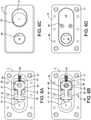
- FIGS. 6A-6D depict the process of assembling locking member 17 into connector plate 5 in one implementation of this disclosure.
- locking member 17 in a first step, may be disposed within locking member housing 43 such that neck portion 53 may be disposed between projections 47, and flanged base 55 may be disposed beneath pull tab bore 37.
- spring 19 may be mounted upon spring guide 57 at one end and disposed within a recessed portion of the internal wall of locking member housing 43 at a second end.
- locking member 17 may be fastened to pull tab 7 by threading screw 65 through bore 59 and pull tab bore 37, thereby fastening locking member 17 to pull tab 7 as shown, for example, in FIGS. 6B and 6C .
- housing cover 49 may be secured to the lower surface of connecting plate 5 so as to cover locking member housing 43.
- housing cover 49 may be secured by fastening screws 67 through bores 61 in housing cover 49 as well as bores 45 in locking member housing 43, although any suitable means of fastening known to one of ordinary skill in the art may be employed.
- FIG. 7 depicts a top view of a surface preparation for a bag or luggage item for securing a strap attachment device in one implementation of this disclosure.
- surface material 69 may comprise any suitable surface material for a bag or luggage item, such as leather, cloth, canvas, silk, wood, plastic, or other suitable baggage materials known to one of ordinary skill in the art.
- surface material 69 may be prepared by cutting an opening 71 that substantially matches the shape and dimensions of locking member housing 43 and/or housing cover 49 in the surface material.
- Surface material 69 may further be prepared by punching one or more holes 73, through which posts 41 are intended to be inserted. In some examples, holes 73 may substantially match the size, shape, and arrangement of posts 41 on connecting plate 5.
- FIG. 8 depicts a bottom view of an optional backing material 75 for a bag or luggage item for securing strap attachment device 1 in one implementation of this disclosure.
- optional backing material 75 may comprise any suitable material for providing additional support to surface material 69 and to prevent unwanted damage to surface material 69 that may be caused by fastening the strap attachment device 1 or from the forces exerted by the strap 23.
- Suitable materials may include leather, cloth, canvas, wood, plastic, rubber, foam, metal, or any other suitable materials known to one of ordinary skill in the art to serve as a backing.
- backing material 75 may be prepared by cutting a section of material that is at least as large as the dimensions of connecting plate 5, but preferably somewhat larger.
- An opening 77 that substantially matches the shape and dimensions of the locking member housing 43, the housing cover 49, or the surface material opening 71 may also be cut in backing 75.
- Backing material 75 may further be prepared by punching one or more holes 79, through which posts 41 are intended to be inserted, similar to the holes 73 on the surface material 69.
- holes 79 may substantially match the size, shape, and arrangement of posts 41 on connecting plate 5.
- FIG. 9 depicts a bottom view of a connection plate 5 after it has been inserted through a surface material 69 and a backing material 75 for a bag or luggage item in one implementation of this disclosure.
- the assembled connection plate 5 is inserted through openings 71 and 77 (as shown in FIGS. 7-8 ) such that housing cover 49 occupies the openings 71, 77 and partially protrudes through the backing material 75.
- Posts 41 may also be inserted through one or more of the holes 73 and 79 (as shown in FIGS. 7-8 ).
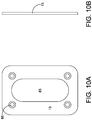
- FIGS. 10A and 10B respectively depict a bottom view and a side view of the backplate 13 according to one implementation of this disclosure.
- the backplate 13 may include a central opening 83 that substantially matches the size and shape of housing cover 49.
- Backplate 13 may also comprise bores or openings 85 that substantially match the size and arrangement of holes 73 and 79, as well as posts 41.
- backplate 13 may secure connection plate 5 upon surface material 69 or backing material 75 via one or more threading screws (not shown), which are inserted through corresponding the bores 85 and holes 73, 79 in order to fasten the backplate 13 to the posts 41.
- mechanical fasteners inserted through bores 85 may not be required and backplate 13 may instead be secured to the connection plate 5 using other suitable means of attachment known to those of ordinary skill in the art.
- the width of the backplate 13 is between 8 mm and 130 mm, for example 32 mm.
- the height of the backplate 13 may be between 11 mm and 190 mm, for example 46 mm.
- the depth of the backplate 13 may be between 0.3 mm and 6 mm, for example 1.3 mm.
- FIGS. 11A and 11B depict perspective views of a fully assembled strap connector in an open and closed position, respectively, according to one implementation of this disclosure.
- strap connector 3 may be inserted into connecting plate 5 by inserting connector post 15 into connector bore 11.
- locking point 51 may engage above the flanged end of connector post 15, thereby temporarily attaching strap connector 3 (and strap 23 ) to connecting plate 5.
- a user need not first disengage locking member 17 before inserting connector post 15. Because connector post 15 may have a curved or rounded lower surface 16, and locking point 51 may be ramped, locking member 17 may retract and engage with connector post 15 using nothing more than a downward force on strap connector 3.
- connecting plate 5, strap connector 3, or connector post 15 may be magnetized so as to help guide strap connector 3 into proper alignment with connector bore 11.
- the locking member 17 may further include a locking point 51 (as shown in FIG. 4A ) adapted to directly abut a body section 18 of connecting post 15 such that the body section 18 may rotate freely relative to the locking member 17 without disengaging the locking member 17 from the connector post 15.
- the locking point 51 may provide a concave leading edge or surface to engage with a cylindrical body section 18 of the connector post 15, allowing an amount of surface area of the concave leading edge abutting the body section 18 to be increased while still allowing for the body section 18 to rotate freely relative to the leading portion of the locking point 51.
- Maximizing the amount of surface area contact between the leading portion of the locking point 51 and the body section 18 of the strap connector 3 may, for example, reduce the likelihood of an accidental or inadvertent disconnection.
- a user may simply pull downward on pull tab 7 thereby disengaging locking member 17 and compressing spring 19 before removing strap connector 3.
Landscapes
- Purses, Travelling Bags, Baskets, Or Suitcases (AREA)
Claims (11)
- Gurtbefestigungsvorrichtung (1), die eine Verbindungsplatte (5), die konfiguriert ist, um an einem Oberflächenmaterial (69) befestigt zu werden, und einen Gurtverbinder (3) beinhaltet, der konfiguriert ist, um an einem Gurt befestigt zu werden, umfassend:die Verbindungsplatte (5), die eine Verbinderbohrung (11) beinhaltet, wobei die Verbindungsplatte (5) entlang einer ersten Ebene ausgerichtet ist;den Gurtverbinder (3), der einen geflanschten Verbinderpfosten (15) beinhaltet, der konfiguriert ist, um entfernbar in die Verbinderbohrung (11) eingesetzt zu werden;ein Verriegelungselement (17), das konfiguriert ist, um entfernbar in den geflanschten Verbinderpfosten (15) einzugreifen, um den geflanschten Verbinderpfosten (15) in einer Eingriffsposition zurückzuhalten, sodass der geflanschte Verbinderpfosten (15) nicht in einer Richtung orthogonal zu der ersten Ebene verschoben werden kann, während er in Eingriff steht, undgekennzeichnet durch einen Stopfen (27), der an dem Gurtverbinder (3) angeordnet ist, wobei der Stopfen (27) einen kreisförmigen Vorsprung (31) aufweist, der konfiguriert ist, um einen Befestigungsabschnitt (26) des geflanschten Verbinderpfostens (15) aufzunehmen, und wobei der kreisförmige Vorsprung (31) konfiguriert ist, um mit einer inneren Oberfläche der Verbinderbohrung (11) zusammenzupassen, sodass der geflanschte Verbinderpfosten (15) nicht in einer Richtung parallel zu der ersten Ebene verschoben werden kann, während er in Eingriff steht, sich jedoch in einer radialen Richtung parallel zu der ersten Ebene drehen kann.
- Gurtbefestigungsvorrichtung (1) nach Anspruch 1, ferner umfassend:eine Zugschiene (9), die auf der Verbindungsplatte (5) angeordnet ist;eine Zuglasche (7), die innerhalb der Zugschiene (9) angeordnet und an dem federbelasteten Verriegelungselement (17) befestigt ist, wobei die Zuglasche (7) konfiguriert ist, um das Verriegelungselement (17) von dem geflanschten Verbinderpfosten (15) als Reaktion auf eine Kraft zu lösen, die bewirkt, dass sich die Zuglasche (7) innerhalb der Zugschiene (9) in einer Richtung parallel zu der ersten Ebene bewegt.
- Gurtbefestigungsvorrichtung (1) nach Anspruch 2, wobei der Gurtverbinder (3) ferner eine T-förmige Stange (21) beinhaltet, die zum Fixieren an dem Gurt konfiguriert und mit dem geflanschten Verbinderpfosten (15) verbunden ist.
- Gurtbefestigungsvorrichtung (1) nach Anspruch 3, wobei das Verriegelungselement (17) ein federbelastetes Verriegelungselement (17) ist, das über eine Feder (19) in die Eingriffsposition vorgespannt wird.
- Gurtbefestigungsvorrichtung (1) nach Anspruch 4, wobei das federbelastete Verriegelungselement (17) ferner einen abgeschrägten Verriegelungspunkt beinhaltet, der an einer Vorderkante des federbelasteten Verriegelungselements (17) positioniert ist, sodass eine abgeschrägte Kante des abgeschrägten Verriegelungspunkts der Verbindungsplatte (5) zugewandt ist.
- Gurtbefestigungsvorrichtung (1) nach Anspruch 5, wobei der geflanschte Verbinderpfosten (15) ferner eine abgerundete untere Oberfläche beinhaltet, die konfiguriert ist, um in den abgeschrägten Verriegelungspunkt einzugreifen, um zu bewirken, dass sich das federbelastete Verriegelungselement (17) zurückzieht, wenn der geflanschte Verbinderpfosten (15) in die Verbindungsbohrung (11) eingesetzt wird und den abgeschrägten Verriegelungspunkt berührt.
- Gurtbefestigungsvorrichtung (1) nach Anspruch 6, wobei der geflanschte Verbinderpfosten (15) ferner einen zylindrischen Körperabschnitt beinhaltet, der oberhalb der abgerundeten unteren Oberfläche angeordnet und konfiguriert ist, um in eine vordere Oberfläche des abgeschrägten Verriegelungspunktes einzugreifen, wenn sich das federbelastete Verriegelungselement (17) in der Eingriffsposition befindet.
- Gurtbefestigungsvorrichtung (1) nach Anspruch 7, wobei die vordere Oberfläche des abgeschrägten Verriegelungspunktes konkav ist und konfiguriert ist, um den zylindrischen Körperabschnitt zu berühren, sodass sich der zylindrische Körperabschnitt frei in einer radialen Richtung relativ zu dem abgeschrägten Verriegelungspunkt drehen kann, ohne dass der Kontakt zwischen der vorderen Oberfläche und dem zylindrischen Körperabschnitt reduziert wird.
- Gurtbefestigungsvorrichtung (1) nach Anspruch 8, ferner umfassend eine an der Verbindungsplatte (5) befestigte Rückplatte (13), wobei die Rückplatte (13) konfiguriert ist, um an einer Oberfläche des Oberflächenmaterials (69) anzuliegen.
- Gurtbefestigungsvorrichtung (1) nach Anspruch 9, ferner umfassend ein Trägermaterial (75), das konfiguriert ist, um zwischen dem Oberflächenmaterial (69) und der Rückplatte (13) angeordnet zu werden.
- Tasche, umfassend:einen Gurt;ein Oberflächenmaterial (69); undeine Gurtbefestigungsvorrichtung (1) nach einem der Ansprüche 1-10.
Applications Claiming Priority (2)
| Application Number | Priority Date | Filing Date | Title |
|---|---|---|---|
| US201662287296P | 2016-01-26 | 2016-01-26 | |
| PCT/US2017/015042 WO2017132317A1 (en) | 2016-01-26 | 2017-01-26 | Strap attachment |
Publications (2)
| Publication Number | Publication Date |
|---|---|
| EP3408546A1 EP3408546A1 (de) | 2018-12-05 |
| EP3408546B1 true EP3408546B1 (de) | 2021-11-10 |
Family
ID=57966212
Family Applications (1)
| Application Number | Title | Priority Date | Filing Date |
|---|---|---|---|
| EP17703615.9A Active EP3408546B1 (de) | 2016-01-26 | 2017-01-26 | Riemenbefestigung |
Country Status (7)
| Country | Link |
|---|---|
| US (2) | US10912361B2 (de) |
| EP (1) | EP3408546B1 (de) |
| JP (1) | JP6923540B2 (de) |
| KR (1) | KR102574618B1 (de) |
| CN (1) | CN108884853B (de) |
| CA (1) | CA3012851A1 (de) |
| WO (1) | WO2017132317A1 (de) |
Families Citing this family (10)
| Publication number | Priority date | Publication date | Assignee | Title |
|---|---|---|---|---|
| WO2012135576A2 (en) | 2011-04-01 | 2012-10-04 | Bowerman James Patrick | Configurable bag having faceplates |
| US11293479B2 (en) | 2019-05-21 | 2022-04-05 | Bowerbags Llc | Modular clipping system |
| KR102417620B1 (ko) * | 2020-04-06 | 2022-07-05 | 노경완 | 가방용 버클 |
| JP7414275B2 (ja) * | 2020-06-26 | 2024-01-16 | 株式会社大阪クリップ | 係合具 |
| CN112205741B (zh) * | 2020-11-12 | 2025-04-08 | 航天晨光股份有限公司 | 一种智能减负背负装置 |
| US11925842B2 (en) | 2020-12-01 | 2024-03-12 | Karsten Manufacturing Corporation | Removable snap-in strap system |
| US12310476B2 (en) | 2021-04-30 | 2025-05-27 | Samsonite Ip Holdings S.A R.L. | Luggage article attachment member |
| US12225991B2 (en) | 2021-04-30 | 2025-02-18 | Samsonite Ip Holdings S.A R.L. | Luggage article attachment member |
| US12557888B2 (en) | 2021-04-30 | 2026-02-24 | Samsonite Ip Holdings S.A R.L. | Luggage article attachment member |
| WO2023019177A2 (en) * | 2021-08-10 | 2023-02-16 | Bowerbags Llc | Modular clipping system |
Family Cites Families (18)
| Publication number | Priority date | Publication date | Assignee | Title |
|---|---|---|---|---|
| US655127A (en) * | 1900-04-25 | 1900-07-31 | Josef Stock | Fastening for wearing-apparel. |
| US2477575A (en) * | 1945-07-14 | 1949-08-02 | Jr Andrew E Bubser | Fastening device |
| US2537750A (en) * | 1949-03-18 | 1951-01-09 | Adolph J Gretschel | Detachable handle for suitcases or other articles |
| US3484894A (en) * | 1967-12-15 | 1969-12-23 | Ltv Electrosystems Inc | Removable handle |
| US3513510A (en) * | 1968-08-08 | 1970-05-26 | Nicholas Copes | Seat belt buckle |
| US3855674A (en) * | 1973-07-26 | 1974-12-24 | R Thiel | Automatic separable fastener |
| JPS5088317U (de) * | 1973-12-12 | 1975-07-26 | ||
| JPH0437460Y2 (de) * | 1987-10-01 | 1992-09-03 | ||
| US5178198A (en) * | 1991-01-30 | 1993-01-12 | F. A. Sontagg, Ltd. | Handbag with replaceable handle |
| JP3393330B2 (ja) * | 1998-07-24 | 2003-04-07 | フルヤ工業株式会社 | ベルト連結用留め具 |
| US6374467B1 (en) * | 2000-09-06 | 2002-04-23 | Wei Chih Chen | Movable buckle device for luggage |
| JP2004153450A (ja) * | 2002-10-29 | 2004-05-27 | Hitachi Ltd | 携帯端末及びこれに取付けるストラップ部品 |
| US6640400B1 (en) | 2002-11-04 | 2003-11-04 | Shou Mao Chen | External strap buckling assembly of luggage |
| JP2004236903A (ja) * | 2003-02-07 | 2004-08-26 | Daito Co Ltd | 鞄等の止め金具 |
| JP2009112678A (ja) * | 2007-11-09 | 2009-05-28 | Raza V Ltd | 連結具およびネックストラップ |
| US9010279B1 (en) * | 2010-08-30 | 2015-04-21 | Chilkoot Trail Ventures, Llc | Leash system and method of use |
| US9066616B2 (en) * | 2010-12-21 | 2015-06-30 | Luxe Link, Llc | Connector assembly for portable hanger |
| CN204359965U (zh) * | 2014-11-20 | 2015-05-27 | 泰科电子(上海)有限公司 | 连接器系统 |
-
2017
- 2017-01-26 KR KR1020187024484A patent/KR102574618B1/ko active Active
- 2017-01-26 WO PCT/US2017/015042 patent/WO2017132317A1/en not_active Ceased
- 2017-01-26 EP EP17703615.9A patent/EP3408546B1/de active Active
- 2017-01-26 CN CN201780018154.5A patent/CN108884853B/zh active Active
- 2017-01-26 US US16/073,032 patent/US10912361B2/en active Active
- 2017-01-26 CA CA3012851A patent/CA3012851A1/en active Pending
- 2017-01-26 JP JP2018539121A patent/JP6923540B2/ja active Active
-
2021
- 2021-02-09 US US17/171,753 patent/US12035789B2/en active Active
Also Published As
| Publication number | Publication date |
|---|---|
| WO2017132317A1 (en) | 2017-08-03 |
| CN108884853B (zh) | 2020-07-10 |
| KR20180105213A (ko) | 2018-09-27 |
| EP3408546A1 (de) | 2018-12-05 |
| US20190029384A1 (en) | 2019-01-31 |
| CA3012851A1 (en) | 2017-08-03 |
| US20210161268A1 (en) | 2021-06-03 |
| JP2019503247A (ja) | 2019-02-07 |
| US10912361B2 (en) | 2021-02-09 |
| US12035789B2 (en) | 2024-07-16 |
| CN108884853A (zh) | 2018-11-23 |
| JP6923540B2 (ja) | 2021-08-18 |
| KR102574618B1 (ko) | 2023-09-05 |
Similar Documents
| Publication | Publication Date | Title |
|---|---|---|
| US12035789B2 (en) | Strap attachment | |
| KR102476517B1 (ko) | 자석 후크 | |
| US9081256B2 (en) | Quick release camera mounting device and methods of use | |
| US6615460B1 (en) | Optionally manual or automatic breakaway lanyard buckle | |
| TWM412106U (en) | Retaining seat for roof rack of automobile | |
| US7254871B2 (en) | Cord lock holder with cord lock, and structure thereof | |
| US6141841A (en) | Add-a-bag assembly for luggage | |
| EP2277768A2 (de) | Einstellbares Motorradmontagesystem | |
| EP3867165B1 (de) | Behälterverbindungssystem | |
| EP2147850A2 (de) | Montagesystem zum Montieren eines Gegenstands auf einem Benzintank eines Motorrads | |
| US8464406B2 (en) | Quick release buckle assembly | |
| US12256827B2 (en) | Modular clipping system | |
| JP5215566B2 (ja) | 紐留め具 | |
| CN118986048A (zh) | 快拆包装置 | |
| US20170258167A1 (en) | Hat clip apparatus | |
| EP1516556B1 (de) | Rückenteile mit einem Hüftgurt und einem Schnellverschluss | |
| CN219556501U (zh) | 快速脱扣结构 | |
| US20030192927A1 (en) | Carrying assembly | |
| US20180220750A1 (en) | Fastener | |
| JPH06233704A (ja) | 袋物類バンドの取付具 | |
| JPH0775605A (ja) | 鞄等の止金具 |
Legal Events
| Date | Code | Title | Description |
|---|---|---|---|
| STAA | Information on the status of an ep patent application or granted ep patent |
Free format text: STATUS: UNKNOWN |
|
| STAA | Information on the status of an ep patent application or granted ep patent |
Free format text: STATUS: THE INTERNATIONAL PUBLICATION HAS BEEN MADE |
|
| PUAI | Public reference made under article 153(3) epc to a published international application that has entered the european phase |
Free format text: ORIGINAL CODE: 0009012 |
|
| STAA | Information on the status of an ep patent application or granted ep patent |
Free format text: STATUS: REQUEST FOR EXAMINATION WAS MADE |
|
| 17P | Request for examination filed |
Effective date: 20180815 |
|
| AK | Designated contracting states |
Kind code of ref document: A1 Designated state(s): AL AT BE BG CH CY CZ DE DK EE ES FI FR GB GR HR HU IE IS IT LI LT LU LV MC MK MT NL NO PL PT RO RS SE SI SK SM TR |
|
| AX | Request for extension of the european patent |
Extension state: BA ME |
|
| DAV | Request for validation of the european patent (deleted) | ||
| DAX | Request for extension of the european patent (deleted) | ||
| REG | Reference to a national code |
Ref country code: DE Ref legal event code: R079 Ref document number: 602017049052 Country of ref document: DE Free format text: PREVIOUS MAIN CLASS: F16B0021070000 Ipc: A45C0013300000 |
|
| GRAP | Despatch of communication of intention to grant a patent |
Free format text: ORIGINAL CODE: EPIDOSNIGR1 |
|
| STAA | Information on the status of an ep patent application or granted ep patent |
Free format text: STATUS: GRANT OF PATENT IS INTENDED |
|
| RIC1 | Information provided on ipc code assigned before grant |
Ipc: A45C 13/30 20060101AFI20210428BHEP |
|
| INTG | Intention to grant announced |
Effective date: 20210519 |
|
| RIN1 | Information on inventor provided before grant (corrected) |
Inventor name: WU, PETER, C. Inventor name: SCICLUNA, PAUL, V. Inventor name: GREISSER, MICHAEL |
|
| GRAS | Grant fee paid |
Free format text: ORIGINAL CODE: EPIDOSNIGR3 |
|
| GRAA | (expected) grant |
Free format text: ORIGINAL CODE: 0009210 |
|
| STAA | Information on the status of an ep patent application or granted ep patent |
Free format text: STATUS: THE PATENT HAS BEEN GRANTED |
|
| AK | Designated contracting states |
Kind code of ref document: B1 Designated state(s): AL AT BE BG CH CY CZ DE DK EE ES FI FR GB GR HR HU IE IS IT LI LT LU LV MC MK MT NL NO PL PT RO RS SE SI SK SM TR |
|
| REG | Reference to a national code |
Ref country code: GB Ref legal event code: FG4D |
|
| REG | Reference to a national code |
Ref country code: AT Ref legal event code: REF Ref document number: 1445249 Country of ref document: AT Kind code of ref document: T Effective date: 20211115 Ref country code: CH Ref legal event code: EP |
|
| REG | Reference to a national code |
Ref country code: DE Ref legal event code: R096 Ref document number: 602017049052 Country of ref document: DE |
|
| REG | Reference to a national code |
Ref country code: IE Ref legal event code: FG4D |
|
| REG | Reference to a national code |
Ref country code: LT Ref legal event code: MG9D |
|
| REG | Reference to a national code |
Ref country code: NL Ref legal event code: MP Effective date: 20211110 |
|
| REG | Reference to a national code |
Ref country code: AT Ref legal event code: MK05 Ref document number: 1445249 Country of ref document: AT Kind code of ref document: T Effective date: 20211110 |
|
| PG25 | Lapsed in a contracting state [announced via postgrant information from national office to epo] |
Ref country code: RS Free format text: LAPSE BECAUSE OF FAILURE TO SUBMIT A TRANSLATION OF THE DESCRIPTION OR TO PAY THE FEE WITHIN THE PRESCRIBED TIME-LIMIT Effective date: 20211110 Ref country code: LT Free format text: LAPSE BECAUSE OF FAILURE TO SUBMIT A TRANSLATION OF THE DESCRIPTION OR TO PAY THE FEE WITHIN THE PRESCRIBED TIME-LIMIT Effective date: 20211110 Ref country code: FI Free format text: LAPSE BECAUSE OF FAILURE TO SUBMIT A TRANSLATION OF THE DESCRIPTION OR TO PAY THE FEE WITHIN THE PRESCRIBED TIME-LIMIT Effective date: 20211110 Ref country code: BG Free format text: LAPSE BECAUSE OF FAILURE TO SUBMIT A TRANSLATION OF THE DESCRIPTION OR TO PAY THE FEE WITHIN THE PRESCRIBED TIME-LIMIT Effective date: 20220210 Ref country code: AT Free format text: LAPSE BECAUSE OF FAILURE TO SUBMIT A TRANSLATION OF THE DESCRIPTION OR TO PAY THE FEE WITHIN THE PRESCRIBED TIME-LIMIT Effective date: 20211110 |
|
| PG25 | Lapsed in a contracting state [announced via postgrant information from national office to epo] |
Ref country code: IS Free format text: LAPSE BECAUSE OF FAILURE TO SUBMIT A TRANSLATION OF THE DESCRIPTION OR TO PAY THE FEE WITHIN THE PRESCRIBED TIME-LIMIT Effective date: 20220310 Ref country code: SE Free format text: LAPSE BECAUSE OF FAILURE TO SUBMIT A TRANSLATION OF THE DESCRIPTION OR TO PAY THE FEE WITHIN THE PRESCRIBED TIME-LIMIT Effective date: 20211110 Ref country code: PT Free format text: LAPSE BECAUSE OF FAILURE TO SUBMIT A TRANSLATION OF THE DESCRIPTION OR TO PAY THE FEE WITHIN THE PRESCRIBED TIME-LIMIT Effective date: 20220310 Ref country code: PL Free format text: LAPSE BECAUSE OF FAILURE TO SUBMIT A TRANSLATION OF THE DESCRIPTION OR TO PAY THE FEE WITHIN THE PRESCRIBED TIME-LIMIT Effective date: 20211110 Ref country code: NO Free format text: LAPSE BECAUSE OF FAILURE TO SUBMIT A TRANSLATION OF THE DESCRIPTION OR TO PAY THE FEE WITHIN THE PRESCRIBED TIME-LIMIT Effective date: 20220210 Ref country code: NL Free format text: LAPSE BECAUSE OF FAILURE TO SUBMIT A TRANSLATION OF THE DESCRIPTION OR TO PAY THE FEE WITHIN THE PRESCRIBED TIME-LIMIT Effective date: 20211110 Ref country code: LV Free format text: LAPSE BECAUSE OF FAILURE TO SUBMIT A TRANSLATION OF THE DESCRIPTION OR TO PAY THE FEE WITHIN THE PRESCRIBED TIME-LIMIT Effective date: 20211110 Ref country code: HR Free format text: LAPSE BECAUSE OF FAILURE TO SUBMIT A TRANSLATION OF THE DESCRIPTION OR TO PAY THE FEE WITHIN THE PRESCRIBED TIME-LIMIT Effective date: 20211110 Ref country code: GR Free format text: LAPSE BECAUSE OF FAILURE TO SUBMIT A TRANSLATION OF THE DESCRIPTION OR TO PAY THE FEE WITHIN THE PRESCRIBED TIME-LIMIT Effective date: 20220211 Ref country code: ES Free format text: LAPSE BECAUSE OF FAILURE TO SUBMIT A TRANSLATION OF THE DESCRIPTION OR TO PAY THE FEE WITHIN THE PRESCRIBED TIME-LIMIT Effective date: 20211110 |
|
| PG25 | Lapsed in a contracting state [announced via postgrant information from national office to epo] |
Ref country code: SM Free format text: LAPSE BECAUSE OF FAILURE TO SUBMIT A TRANSLATION OF THE DESCRIPTION OR TO PAY THE FEE WITHIN THE PRESCRIBED TIME-LIMIT Effective date: 20211110 Ref country code: SK Free format text: LAPSE BECAUSE OF FAILURE TO SUBMIT A TRANSLATION OF THE DESCRIPTION OR TO PAY THE FEE WITHIN THE PRESCRIBED TIME-LIMIT Effective date: 20211110 Ref country code: RO Free format text: LAPSE BECAUSE OF FAILURE TO SUBMIT A TRANSLATION OF THE DESCRIPTION OR TO PAY THE FEE WITHIN THE PRESCRIBED TIME-LIMIT Effective date: 20211110 Ref country code: EE Free format text: LAPSE BECAUSE OF FAILURE TO SUBMIT A TRANSLATION OF THE DESCRIPTION OR TO PAY THE FEE WITHIN THE PRESCRIBED TIME-LIMIT Effective date: 20211110 Ref country code: DK Free format text: LAPSE BECAUSE OF FAILURE TO SUBMIT A TRANSLATION OF THE DESCRIPTION OR TO PAY THE FEE WITHIN THE PRESCRIBED TIME-LIMIT Effective date: 20211110 Ref country code: CZ Free format text: LAPSE BECAUSE OF FAILURE TO SUBMIT A TRANSLATION OF THE DESCRIPTION OR TO PAY THE FEE WITHIN THE PRESCRIBED TIME-LIMIT Effective date: 20211110 |
|
| REG | Reference to a national code |
Ref country code: DE Ref legal event code: R097 Ref document number: 602017049052 Country of ref document: DE |
|
| PG25 | Lapsed in a contracting state [announced via postgrant information from national office to epo] |
Ref country code: MC Free format text: LAPSE BECAUSE OF FAILURE TO SUBMIT A TRANSLATION OF THE DESCRIPTION OR TO PAY THE FEE WITHIN THE PRESCRIBED TIME-LIMIT Effective date: 20211110 |
|
| REG | Reference to a national code |
Ref country code: CH Ref legal event code: PL |
|
| PLBE | No opposition filed within time limit |
Free format text: ORIGINAL CODE: 0009261 |
|
| STAA | Information on the status of an ep patent application or granted ep patent |
Free format text: STATUS: NO OPPOSITION FILED WITHIN TIME LIMIT |
|
| REG | Reference to a national code |
Ref country code: BE Ref legal event code: MM Effective date: 20220131 |
|
| 26N | No opposition filed |
Effective date: 20220811 |
|
| PG25 | Lapsed in a contracting state [announced via postgrant information from national office to epo] |
Ref country code: LU Free format text: LAPSE BECAUSE OF NON-PAYMENT OF DUE FEES Effective date: 20220126 Ref country code: AL Free format text: LAPSE BECAUSE OF FAILURE TO SUBMIT A TRANSLATION OF THE DESCRIPTION OR TO PAY THE FEE WITHIN THE PRESCRIBED TIME-LIMIT Effective date: 20211110 |
|
| PG25 | Lapsed in a contracting state [announced via postgrant information from national office to epo] |
Ref country code: SI Free format text: LAPSE BECAUSE OF FAILURE TO SUBMIT A TRANSLATION OF THE DESCRIPTION OR TO PAY THE FEE WITHIN THE PRESCRIBED TIME-LIMIT Effective date: 20211110 Ref country code: BE Free format text: LAPSE BECAUSE OF NON-PAYMENT OF DUE FEES Effective date: 20220131 |
|
| PG25 | Lapsed in a contracting state [announced via postgrant information from national office to epo] |
Ref country code: LI Free format text: LAPSE BECAUSE OF NON-PAYMENT OF DUE FEES Effective date: 20220131 Ref country code: CH Free format text: LAPSE BECAUSE OF NON-PAYMENT OF DUE FEES Effective date: 20220131 |
|
| PG25 | Lapsed in a contracting state [announced via postgrant information from national office to epo] |
Ref country code: IE Free format text: LAPSE BECAUSE OF NON-PAYMENT OF DUE FEES Effective date: 20220126 |
|
| PG25 | Lapsed in a contracting state [announced via postgrant information from national office to epo] |
Ref country code: IT Free format text: LAPSE BECAUSE OF FAILURE TO SUBMIT A TRANSLATION OF THE DESCRIPTION OR TO PAY THE FEE WITHIN THE PRESCRIBED TIME-LIMIT Effective date: 20211110 |
|
| P01 | Opt-out of the competence of the unified patent court (upc) registered |
Effective date: 20230601 |
|
| PG25 | Lapsed in a contracting state [announced via postgrant information from national office to epo] |
Ref country code: HU Free format text: LAPSE BECAUSE OF FAILURE TO SUBMIT A TRANSLATION OF THE DESCRIPTION OR TO PAY THE FEE WITHIN THE PRESCRIBED TIME-LIMIT; INVALID AB INITIO Effective date: 20170126 |
|
| PG25 | Lapsed in a contracting state [announced via postgrant information from national office to epo] |
Ref country code: MK Free format text: LAPSE BECAUSE OF FAILURE TO SUBMIT A TRANSLATION OF THE DESCRIPTION OR TO PAY THE FEE WITHIN THE PRESCRIBED TIME-LIMIT Effective date: 20211110 Ref country code: CY Free format text: LAPSE BECAUSE OF FAILURE TO SUBMIT A TRANSLATION OF THE DESCRIPTION OR TO PAY THE FEE WITHIN THE PRESCRIBED TIME-LIMIT Effective date: 20211110 |
|
| PG25 | Lapsed in a contracting state [announced via postgrant information from national office to epo] |
Ref country code: TR Free format text: LAPSE BECAUSE OF FAILURE TO SUBMIT A TRANSLATION OF THE DESCRIPTION OR TO PAY THE FEE WITHIN THE PRESCRIBED TIME-LIMIT Effective date: 20211110 |
|
| PG25 | Lapsed in a contracting state [announced via postgrant information from national office to epo] |
Ref country code: MT Free format text: LAPSE BECAUSE OF FAILURE TO SUBMIT A TRANSLATION OF THE DESCRIPTION OR TO PAY THE FEE WITHIN THE PRESCRIBED TIME-LIMIT Effective date: 20211110 |
|
| PGFP | Annual fee paid to national office [announced via postgrant information from national office to epo] |
Ref country code: GB Payment date: 20260127 Year of fee payment: 10 |
|
| PGFP | Annual fee paid to national office [announced via postgrant information from national office to epo] |
Ref country code: DE Payment date: 20260128 Year of fee payment: 10 |
|
| PGFP | Annual fee paid to national office [announced via postgrant information from national office to epo] |
Ref country code: FR Payment date: 20260126 Year of fee payment: 10 |