EP3407438A1 - Steckverbindungssystem zur zündsicheren, elektrisch abgeschirmten kontaktierung mit einer zündpille - Google Patents
Steckverbindungssystem zur zündsicheren, elektrisch abgeschirmten kontaktierung mit einer zündpille Download PDFInfo
- Publication number
- EP3407438A1 EP3407438A1 EP18165500.2A EP18165500A EP3407438A1 EP 3407438 A1 EP3407438 A1 EP 3407438A1 EP 18165500 A EP18165500 A EP 18165500A EP 3407438 A1 EP3407438 A1 EP 3407438A1
- Authority
- EP
- European Patent Office
- Prior art keywords
- connector
- plug
- contact
- ring contact
- housing
- Prior art date
- Legal status (The legal status is an assumption and is not a legal conclusion. Google has not performed a legal analysis and makes no representation as to the accuracy of the status listed.)
- Granted
Links
Images


Classifications
-
- H—ELECTRICITY
- H01—ELECTRIC ELEMENTS
- H01R—ELECTRICALLY-CONDUCTIVE CONNECTIONS; STRUCTURAL ASSOCIATIONS OF A PLURALITY OF MUTUALLY-INSULATED ELECTRICAL CONNECTING ELEMENTS; COUPLING DEVICES; CURRENT COLLECTORS
- H01R13/00—Details of coupling devices of the kinds covered by groups H01R12/70 or H01R24/00 - H01R33/00
- H01R13/66—Structural association with built-in electrical component
- H01R13/70—Structural association with built-in electrical component with built-in switch
- H01R13/703—Structural association with built-in electrical component with built-in switch operated by engagement or disengagement of coupling parts, e.g. dual-continuity coupling part
- H01R13/7031—Shorting, shunting or bussing of different terminals interrupted or effected on engagement of coupling part, e.g. for ESD protection, line continuity
- H01R13/7034—Shorting, shunting or bussing of different terminals interrupted or effected on engagement of coupling part, e.g. for ESD protection, line continuity the terminals being in direct electric contact separated by double sided connecting element
-
- F—MECHANICAL ENGINEERING; LIGHTING; HEATING; WEAPONS; BLASTING
- F42—AMMUNITION; BLASTING
- F42B—EXPLOSIVE CHARGES, e.g. FOR BLASTING, FIREWORKS, AMMUNITION
- F42B3/00—Blasting cartridges, i.e. case and explosive
- F42B3/10—Initiators therefor
- F42B3/18—Safety initiators resistant to premature firing by static electricity or stray currents
- F42B3/182—Safety initiators resistant to premature firing by static electricity or stray currents having shunting means
-
- F—MECHANICAL ENGINEERING; LIGHTING; HEATING; WEAPONS; BLASTING
- F42—AMMUNITION; BLASTING
- F42B—EXPLOSIVE CHARGES, e.g. FOR BLASTING, FIREWORKS, AMMUNITION
- F42B39/00—Packaging or storage of ammunition or explosive charges; Safety features thereof; Cartridge belts or bags
- F42B39/30—Containers for detonators or fuzes
-
- H—ELECTRICITY
- H01—ELECTRIC ELEMENTS
- H01R—ELECTRICALLY-CONDUCTIVE CONNECTIONS; STRUCTURAL ASSOCIATIONS OF A PLURALITY OF MUTUALLY-INSULATED ELECTRICAL CONNECTING ELEMENTS; COUPLING DEVICES; CURRENT COLLECTORS
- H01R2201/00—Connectors or connections adapted for particular applications
- H01R2201/26—Connectors or connections adapted for particular applications for vehicles
Definitions
- the present invention relates to a connector system for ignition-proof, electrically shielded contacting with a squib comprising a connector for electrically shielded storage of the squib and a plug for insertion into such a connector.
- Electric squibs ie, electrically ignited igniters for pyrotechnic substances, are used in various technical fields to selectively trigger processes.
- electric squibs contain a pyrotechnic charge which can be ignited by a current flow through two electrical contacts provided for this purpose.
- a gas generator to trigger an airbag in a motor vehicle, see. for example, the publications DE 10 2006 032 927 A1 .
- EP 1 378 973 B1 and EP 1 689 047 B1 are used for example in belt tensioners of vehicles, in exhaust and cruise engines or as a detonator for ammunition.
- the present invention seeks to find solutions that effectively prevent accidental ignition of squibs outside the actual use.
- this object is achieved by a connector having the features of patent claim 1, by a plug having the features of patent claim 9 and by a plug connection system having the features of patent claim 15.
- a connector for electrically shielded storage of a squib includes a squib.
- the connector further includes a connector center contact.
- the connector further includes a connector ring contact coaxially surrounding the connector center contact.
- the connector ring contact and the connector center contact are electrically connected to the squib for igniting the squib.
- the connector further includes a connector housing coaxially surrounding the connector ring contact.
- the connector further comprises an inner spring element, via which the connector center contact is einfederbar in the connector housing.
- the connector further comprises an outer spring element, via which the connector ring contact is einfederbar in the connector housing.
- the connector center contact is with the connector ring contact to prevent inadvertent ignition of the Squib shorted in a stored condition.
- the connector ring contact is shorted to the connector housing to prevent inadvertent ignition of the squib in the stored condition.
- the short circuit of the connector center contact with the connector ring contact can be canceled by springing the connector center contact into the connector housing for use with the squib.
- the short circuit of the connector ring contact with the connector housing can be canceled by compression of the connector ring contact in the connector housing for use of the squib.
- a plug for insertion into a connector includes a male center contact.
- the plug further includes a male-ring contact coaxially surrounding the male center contact.
- the plug further includes a plug housing coaxially surrounding the plug ring contact. The plug is formed such that the plug connector center contact is spring-loaded by the plug center contact and the plug connector ring contact by the plug ring contact into the plug connector housing upon insertion of the plug into the plug connector.
- the plug-in system comprises a plug-in connector functioning as a "socket" and a corresponding plug.
- the connector is provided with movable, spring-loaded, coaxial inner contacts, which short-circuit the two inner conductors with each other and against the housing ground in a storage condition of the squib.
- this double short circuit is to some extent automatically released by inserting the plug by overcoming the spring forces of the spring elements and opening the shorts by the movement of the contacts into the interior of the connector.
- the plug-in system can be designed differently, depending on whether this process is to be performed only once (eg in the form of a snap closure or a one-time latching plug-in operation) or whether the connection should be solvable (eg in the form of a screw). In any case, the assembly is particularly simple, since only the plug must be inserted into the connector.
- the connector may further comprise an inner connector insulating piece between the connector center contact and the connector ring contact include.
- the connector may further comprise an outer connector insulating piece between the connector ring contact and the connector housing.
- the inner connector insulating piece may coaxially surround the connector center contact.
- the outer connector isolator may coaxially surround the connector ring contact.
- the connector center contact can contact the connector ring contact in a plug-in region of the connector in the stored state.
- the plug connector ring contact can contact the plug connector housing in a plug-in region of the plug connector in the stored state.
- the connector center contact, the connector ring contact and the connector housing may be cylindrically symmetrical, the connector housing coaxially surrounding the connector ring contact and the connector ring contact in turn coaxially surrounding the connector center contact.
- the squib may in this case be arranged at one of the axial ends of the device, while touching the three components at their end faces at the opposite axial end, so that the end faces form short-circuited surfaces.
- the components can advantageously be dimensioned such that the end faces simultaneously serve as an inner boundary for the mobility of the contacts, ie the connector center contact and the connector ring contact axially between a storage position (in which the connector center contact, the connector ring contact and touching the connector housing at the end faces and being shorted such) and a use position (in which the connector center contact and the connector ring contact are spring-loaded into the connector housing in the direction of the squib) are movably arranged.
- the lateral surface of the connector center contact may for example be surrounded by an inner connector insulating piece. Accordingly, the lateral surface of the connector ring contact may be surrounded by an outer connector insulating piece.
- the connector insulating pieces may be formed, for example, circular cylindrical.
- the inner spring element may be formed as a compression spring between the connector center contact and the squib.
- the outer spring element may be formed as a compression spring between the connector ring contact and the squib.
- the spring elements may be formed, for example, as a cylinder spring, coil spring or torsion spring or the like.
- the inner spring element may be formed metallic.
- the outer spring element may be formed metallic.
- the spring elements may consist entirely or predominantly of a metal, a metal alloy or a metallic material or be coated with such.
- the connector housing can taper in a plug-in region of the connector to the outside.
- the connector housing may be in the shape of a hollow truncated cone or generally frustoconical shaped.
- the connector housing in the plug-in area to some extent forms a kind of centering ramp or contact surface, which serves as a guide for the plug when plugging the plug and this is practically automatically centered inserted into the connector.
- the connector housing may be formed as a screw, snap element or as a latching element or the like. Accordingly, the plug housing may be complementary to the connector housing as Martinezschraubelement, Gegenschnappelement or as a counter-latching element or the like.
- the plug housing may be formed with a support surface for a cable shield.
- a shielding braid for improved shielding of the system from external EMF or EMP be placed.
- the plug may further comprise an inner plug insulating piece between the plug center contact and the plug ring contact. According to a further development, the plug may further comprise an outer plug insulating piece between the plug ring contact and the plug housing.
- the inner plug insulating piece can coaxially surround the plug center contact.
- the outer plug insulating piece can coaxially surround the plug ring contact.
- the plug can be connected to a coaxial ignition lead for igniting the squib.
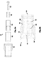
- FIG. 1a shows a schematic sectional view of the individual parts of a connector 1 according to an embodiment of the invention.
- FIG. 1b shows a schematic sectional view of the individual parts of a connector 1 according to another embodiment of the invention.
- Fig. 1c represents a schematic sectional view of the connector 1 Fig. 1a in assembled form.
- the connector 1 forms together with a in Fig. 2a-b shown connector 10, a plug-in connection system which serves for ignition-proof, electrically shielded contacting with a squib 7.
- Fig. 2a shows a schematic sectional view of the individual parts of a plug 10 according to an embodiment of the invention.
- Fig. 2b shows a schematic sectional view of the plug 10 Fig. 2a in assembled form.
- a squib in the context of the invention is a general, electrically ignited ignition means for pyrotechnic substances (English: "Squib"), which is used for example in airbags and / or belt tensioners or similar vehicle components.
- embodiments of the present invention can also be used in missiles, for example in exhaust and cruise engines or as a primer for general ammunition.
- the present connector system can be used in any applications in which a squib or the like ignition means against the influence of external electromagnetic fields (EMF) or pulses (EMP) to be protected or shielded from these should and should generally improve the electromagnetic compatibility (EMC) of such an element.
- EMF external electromagnetic fields
- EMP pulses
- the present system will increase handling safety in the area of EMF radiation specific to missiles during assembly, transportation, and / or maintenance.
- EMP lightning
- NEMP nuclear electromagnetic pulses
- the connector 1 comprises a squib 7, e.g. for triggering a motor vehicle airbag.
- the squib 7 has in this purely exemplary embodiment of the invention, a squib-center contact 22 and a squib ring contact 23.
- the connector 1 further comprises a connector center contact 2 and a connector ring contact 3.
- the connector ring contact 3 coaxially surrounds the connector center contact 2 in the assembled state (in this exemplary embodiment, all system components can be assembled by simply mating).
- the connector ring contact 3 and the connector center contact 2 are electrically connected to the squib 7 for igniting the squib 7.
- an inner connector insulating piece 5 is also coaxially positioned, which isolates the two components from each other on their lateral surfaces.
- the connector 1 further comprises a connector housing 4, which in turn coaxially surrounds the connector ring contact 3. Also between the connector ring contact 3 and the connector housing 4, an outer connector insulating piece 6 is inserted. In interaction, these components thus form a "double-coaxial" arranged system, wherein at one axial end of the connector 1, the squib 7 is arranged, while the opposite axial end of the connector 1, a plug-in portion 11 for the plug 10 forms.
- the plug 10 is provided with a male center contact 12, a male ring contact 13 and a male housing 14 and an inner male insulating piece 15 between the male center contact 12 and the male ring contact 13 and an outer male insulating piece 16 therebetween the plug-ring contact 13 and the plug housing 14 are formed, which are each arranged coaxially.
- Both the contacts 2, 3, 12, 13 and the housing 4, 14 may be formed metallic, ie be formed for example of a metal, a metal alloy or a metallic material.
- the connector 1 further comprises an inner spring element 8, which is arranged between the connector center contact 2 and the squib 7 and via which the connector center contact 2 in the connector housing 4 in the direction of the squib 7 is einfederbar.
- the spring element 8 is in the FIGS. 1a and 1c only shown schematically.
- the spring element 8 may be a compression spring, for example a cylinder spring or the like, which is made of, for example, metal or a metallic material or at least is coated with such a metal.
- Such an exemplary embodiment of the spring element 8 is in Fig. 1b shown.
- suitable spring elements can be used, which fulfill the purpose explained in more detail below, such as torsion springs etc.
- the connector 1 further comprises an outer spring element 9, which between the connector ring contact 3 and the Squib 7 is arranged and via which the connector ring contact 3 in the connector housing 4 in the direction of the squib 7 is einfederbar.
- the plug 10 is formed correspondingly complementary, so that the connector center contact 2 are spring-loaded by the plug center contact 12 and the connector ring contact 3 through the plug ring contact 13 in the connector housing 4 during insertion of the plug 10 into the connector 1 ,
- the connector center contact 2 is short-circuited to the connector ring contact 3 to prevent inadvertent ignition of the squib 7 in a stored state, that is, in a state of the system in which the connector 10 is not inserted into the connector 1. Accordingly, the connector ring contact 3 is short-circuited to the connector housing 4 to prevent inadvertent ignition of the squib 7 in the stored state.
- the corresponding contact surfaces form short-circuit surfaces 18, which in Fig. 1c Marked are. This short circuit of the connector center contact 2 with the connector ring contact 3 is canceled by compression of the connector center contact 2 in the connector housing 4 upon insertion of the connector 10 in the connector 1.
- the short circuit of the connector ring contact 3 with the connector housing 4 is released by springing the connector ring contact 3 into the connector housing 4 upon insertion of the connector 10 into the connector housing 4.
- the connector center contact 2 and the male center contact 12, and the male ring contact 3 and the male ring contact 13 may be arranged and configured such that upon insertion of the male connector 10, first, the short circuit of the male connector center contact 2 with the connector ring contact 3 is lifted and only then the short circuit of the connector ring contact 3 with the connector housing 4.
- the connector center contact 2 is formed with a pin-like projection at the axial end, which is aligned in the plug-in area 11 ,
- the present connector system ensures the shorting of the two coaxial inner conductors with each other and beyond with the surrounding housing, so that upon occurrence of external EMF or EMP, no formation of electrical voltages or currents in the protected area can come.
- the plug 10 causes by its special design a separation of the two shorts in the connector 1.
- the connector housing 4 can be used as a screw, snap element or as a locking element or further the skilled person be formed common connection system.
- the plug housing 14 may be complementary to the connector housing 4 as Terylatching element or be designed accordingly.
- the connector housing 4 tapers in the plug-in region 11 of the connector 1 to the outside, so that a Zentri mecanicsrampe 17 is formed as a result, over which the plug 10 is introduced to a certain extent self-centering, without a complicated prior mechanical Vororienttechnik the Components is necessary.
- the system is configured as a snap-fit system having a plurality of snap elements 19 on the plug 10, which ensure that the plug 10 snaps firmly into the connector 1, ie, is locked thereto. This allows a particularly simple and quick installation.
- embodiments are also provided which are detachably designed, for example by means of a screw mechanism or the like.
- the plug 10 may be connected to a coaxial ignition lead 21 for igniting the squib 7 (whose positioning is in FIG Fig. 2b indicated by reference numeral 21).
- the plug housing 14 is formed for general shielding, for example against unwanteddersindutationen by external electric fields or pulses on the coaxial ignition lead 21, with a support surface 20 for a cable shield.
- a backup against accidental ignition eg in the form of a responsible for the ignition chain safety device, such as a "safety and arming unit".
Landscapes
- Engineering & Computer Science (AREA)
- General Engineering & Computer Science (AREA)
- Details Of Connecting Devices For Male And Female Coupling (AREA)
- Air Bags (AREA)
- Coupling Device And Connection With Printed Circuit (AREA)
Abstract
Description
- Die vorliegende Erfindung betrifft ein Steckverbindungssystem zur zündsicheren, elektrisch abgeschirmten Kontaktierung mit einer Zündpille umfassend einen Steckverbinder zur elektrisch abgeschirmten Lagerung der Zündpille und einen Stecker zum Einstecken in einen derartigen Steckverbinder.
- Elektrische Zündpillen, d.h. elektrisch gezündete Anzündmittel für pyrotechnische Stoffe, werden in unterschiedlichen technischen Gebieten verwendet, um gezielt Prozesse auszulösen. Elektrische Zündpillen enthalten hierzu eine pyrotechnische Ladung, welche durch einen Stromfluss durch zwei hierfür vorgesehene elektrische Kontakte gezündet werden kann. Beispielsweise kann mit der pyrotechnischen Ladung ein Gasgenerator getrieben werden, um einen Airbag in einem Kraftfahrzeug auszulösen, vgl. beispielsweise die Druckschriften
DE 10 2006 032 927 A1 ,EP 1 378 973 B1 undEP 1 689 047 B1 . Weiterhin werden derartige Zündpillen beispielsweise in Gurtstraffern von Fahrzeugen, in Ausstoß- und Marschtriebwerken oder als Zündmittel für Munitionen verwendet. - Grundsätzlich besteht bei bekannten Zündpillen je nach Anwendungsfall eine mehr oder weniger große Gefahr einer unbeabsichtigten Zündung durch eingestrahlte elektromagnetische Felder (EMF) oder Impulse (EMP), da diese zu einer Ausbildung von elektrischen Spannungen oder Strömen innerhalb der elektrischen Komponenten führen können. Es besteht somit ein genereller Bedarf nach einer möglichst effizienten Abschirmung sowohl der Zündpille als solcher als auch der diese enthaltenen Vorrichtungen. Insbesondere besteht ein Bedarf, die Handhabungssicherheit hinsichtlich der Einstrahlung von EMF und EMP während der Montage, dem Transport und der Wartung der die Zündpille enthaltenen Vorrichtung, z.B. einem Flugkörper, zu erhöhen.
- Vor diesem Hintergrund liegt der vorliegenden Erfindung die Aufgabe zugrunde, Lösungen zu finden, welche eine unbeabsichtigte Zündung von Zündpillen auch außerhalb des eigentlichen Gebrauchs wirksam vermeiden.
- Erfindungsgemäß wird diese Aufgabe gelöst durch einen Steckverbinder mit den Merkmalen des Patentanspruchs 1, durch einen Stecker mit den Merkmalen des Patentanspruchs 9 und durch ein Steckverbindungssystem mit den Merkmalen des Patentanspruchs 15.
- Demgemäß ist ein Steckverbinder zur elektrisch abgeschirmten Lagerung einer Zündpille vorgesehen. Der Steckverbinder umfasst eine Zündpille. Der Steckverbinder umfasst ferner einen Steckverbinder-Mittelkontakt. Der Steckverbinder umfasst ferner einen Steckverbinder-Ringkontakt, welcher den Steckverbinder-Mittelkontakt koaxial umgibt. Der Steckverbinder-Ringkontakt und der Steckverbinder-Mittelkontakt sind elektrisch mit der Zündpille zur Zündung der Zündpille verbunden. Der Steckverbinder umfasst ferner ein Steckverbinder-Gehäuse, welches den Steckverbinder-Ringkontakt koaxial umgibt. Der Steckverbinder umfasst ferner ein inneres Federelement, über welches der Steckverbinder-Mittelkontakt in das Steckverbinder-Gehäuse einfederbar ist. Der Steckverbinder umfasst ferner ein äußeres Federelement, über welches der Steckverbinder-Ringkontakt in das Steckverbinder-Gehäuse einfederbar ist. Der Steckverbinder-Mittelkontakt ist mit dem Steckverbinder-Ringkontakt zur Vermeidung einer unbeabsichtigten Zündung der Zündpille in einem Lagerzustand kurzgeschlossen. Der Steckverbinder-Ringkontakt ist mit dem Steckverbinder-Gehäuse zur Vermeidung einer unbeabsichtigten Zündung der Zündpille in dem Lagerzustand kurzgeschlossen. Der Kurzschluss des Steckverbinder-Mittelkontakts mit dem Steckverbinder-Ringkontakt ist durch Einfedern des Steckverbinder-Mittelkontakts in das Steckverbinder-Gehäuse zum Gebrauch der Zündpille aufhebbar. Der Kurzschluss des Steckverbinder-Ringkontakts mit dem Steckverbinder-Gehäuse ist durch Einfedern des Steckverbinder-Ringkontakts in das Steckverbinder-Gehäuse zum Gebrauch der Zündpille aufhebbar.
- Ferner ist ein Stecker zum Einstecken in einen erfindungsgemäßen Steckverbinder vorgesehen. Der Stecker umfasst einen Stecker-Mittelkontakt. Der Stecker umfasst ferner einen Stecker-Ringkontakt, welcher den Stecker-Mittelkontakt koaxial umgibt. Der Stecker umfasst ferner ein Stecker-Gehäuse, welches den Stecker-Ringkontakt koaxial umgibt. Der Stecker ist derart ausgebildet, dass der Steckverbinder-Mittelkontakt durch den Stecker-Mittelkontakt und der Steckverbinder-Ringkontakt durch den Stecker-Ringkontakt in das Steckverbinder-Gehäuse beim Einführen des Steckers in den Steckverbinder eingefedert werden.
- Ferner ist ein Steckverbindungssystem mit einem erfindungsgemäßen Steckverbinder und einem erfindungsgemäßen Stecker vorgesehen.
- Eine der vorliegenden Erfindung zugrunde liegende Idee besteht darin, die Gefahr einer unbeabsichtigten Zündung eine elektrischen Zündpille durch EMF oder EMP zu verringern, indem ein Stecksystem mit einem doppelt koaxialen Aufbau bereitgestellt wird. Das Stecksystem umfasst einen als "Steckdose" fungierenden Steckverbinder und einen entsprechenden Stecker. Während des Transports, der Lagerung oder dem Ruhezustand der Zündpille wird der Steckverbinder getrennt von dem Stecker aufbewahrt. Für den Gebrauch muss der Stecker lediglich in den Steckverbinder eingesteckt werden. Der Steckverbinder ist mit beweglichen, gefederten, koaxialen Innenkontakten versehen, welche die beiden Innenleiter miteinander und gegen die Gehäusemasse in einem Lagerzustand der Zündpille kurzschließen. In einem Gebrauchszustand wird dieser doppelte Kurzschluss gewissermaßen selbsttätig durch Einführen des Steckers aufgehoben, indem die Federkräfte der Federelemente überwunden werden und die Kurzschlüsse durch die Bewegung der Kontakte in das Innere des Steckverbinders hinein geöffnet werden. Das Stecksystem kann unterschiedlich ausgebildet werden, je nachdem ob dieser Vorgang lediglich einmalig durchgeführt werden soll (z.B. in Form eines Schnappverschlusses oder eines einmalig rastenden Steckvorgangs) oder ob die Verbindung lösbar sein soll (z.B. in Form einer Schraubverbindung). In jedem Fall gestaltet sich die Montage besonders einfach, da lediglich der Stecker in den Steckverbinder eingesteckt werden muss. In dem vollständig montierten Gebrauchszustand des Systems kann dann in üblicher Weise eine Sicherung vor einer versehentlichen Zündung verwendet werden, z.B. in Form einer für die Zündkette verantwortlichen Sicherungseinrichtung (beispielsweise einer so genannten "Safety and Arming Unit - SAU"). Dieser doppel-koaxiale Aufbau des Steckverbindungssystems bietet darüber hinaus den weiteren Vorteil, dass ohne weitere Vorkehrungen geschirmte, koaxiale Zuleitungen verwendet werden können. Beispielsweise kann ein Koaxialkabel direkt als Zündungs-Zuleitung zur Zündung der Zündpille an den Stecker angeschlossen werden.
- Vorteilhafte Ausgestaltungen und Weiterbildungen ergeben sich aus den weiteren Unteransprüchen sowie aus der Beschreibung unter Bezugnahme auf die Figuren.
- Gemäß einer Weiterbildung kann der Steckverbinder ferner ein inneres Steckverbinder-Isolierstück zwischen dem Steckverbinder-Mittelkontakt und dem Steckverbinder-Ringkontakt umfassen. Gemäß einer Weiterbildung kann der Steckverbinder ferner ein äußeres Steckverbinder-Isolierstück zwischen dem Steckverbinder-Ringkontakt und dem Steckverbinder-Gehäuse umfassen.
- Das innere Steckverbinder-Isolierstück kann den Steckverbinder-Mittelkontakt koaxial umgeben. Das äußere Steckverbinder-Isolierstück kann den Steckverbinder-Ringkontakt koaxial umgeben.
- Gemäß einer Weiterbildung kann der Steckverbinder-Mittelkontakt den Steckverbinder-Ringkontakt in einem Steckbereich des Steckverbinders in dem Lagerzustand berühren. Gemäß einer Weiterbildung kann der Steckverbinder-Ringkontakt das Steckverbinder-Gehäuse in einem Steckbereich des Steckverbinders in dem Lagerzustand berühren. Beispielsweise können der Steckverbinder-Mittelkontakt, der Steckverbinder-Ringkontakt und das Steckverbinder-Gehäuse zylindersymmetrisch ausgebildet sein, wobei das Steckverbinder-Gehäuse den Steckverbinder-Ringkontakt koaxial umgibt und der Steckverbinder-Ringkontakt wiederum den Steckverbinder-Mittelkontakt koaxial umgibt. Die Zündpille kann hierbei an einem der axialen Enden der Vorrichtung angeordnet sein, während sich die drei Bauteile an ihren Stirnflächen an dem gegenüberliegenden axialen Ende berühren, sodass die Stirnflächen Kurzschlussflächen bilden. Die Bauteile können hierbei vorteilhafterweise derart dimensioniert werden, dass die Stirnflächen gleichzeitig als innere Begrenzung für die Beweglichkeit der Kontakte dienen, d.h. der Steckverbinder-Mittelkontakt und der Steckverbinder-Ringkontakt axial zwischen einer Lagerposition (in welcher sich der Steckverbinder-Mittelkontakt, der Steckverbinder-Ringkontakt und das Steckverbinder-Gehäuse an den Stirnflächen berühren und derart kurzgeschlossen sind) und einer Gebrauchsposition (in welche der Steckverbinder-Mittelkontakt und der Steckverbinder-Ringkontakt in das Steckverbinder-Gehäuse in Richtung der Zündpille eingefedert sind) beweglich angeordnet sind.
- Die Mantelfläche des Steckverbinder-Mittelkontakts kann beispielsweise von einem inneren Steckverbinder-Isolierstück umgeben sein. Entsprechend kann die Mantelfläche des Steckverbinder-Ringkontakts von einem äußeren Steckverbinder-Isolierstück umgeben sein. Die Steckverbinder-Isolierstücke könne beispielsweise kreiszylinderförmig ausgebildet sein.
- Gemäß einer Weiterbildung kann das innere Federelement als Druckfeder zwischen dem Steckverbinder-Mittelkontakt und der Zündpille ausgebildet sein. Gemäß einer Weiterbildung kann das äußere Federelement als Druckfeder zwischen dem Steckverbinder-Ringkontakt und der Zündpille ausgebildet sein. Die Federelemente können beispielsweise als Zylinderfeder, Schraubenfeder oder Drehfeder oder dergleichen ausgebildet sein.
- Gemäß einer Weiterbildung kann das innere Federelement metallisch ausgebildet sein. Gemäß einer Weiterbildung kann das äußere Federelement metallisch ausgebildet sein. Beispielsweise können die Federelemente vollständig oder überwiegend aus einem Metall, einer Metalllegierung oder einem metallischen Werkstoff bestehen oder mit einem solchen beschichtet sein.
- Gemäß einer Weiterbildung kann sich das Steckverbinder-Gehäuse in einem Steckbereich des Steckverbinders nach außen hin verjüngen. Beispielsweise kann das Steckverbinder-Gehäuse die Form eines hohlen Kegelstumpfes aufweisen oder allgemein kegelstumpfartig geformt sein. In dieser Weiterbildung bildet das Steckverbinder-Gehäuse in dem Steckbereich gewissermaßen eine Art Zentrierungsrampe oder Anlauffläche, welche beim Aufstecken des Steckers als Führung für den Stecker dient und dieser praktisch automatisch zentriert in den Steckverbinder eingeführt wird.
- Gemäß einer Weiterbildung kann das Steckverbinder-Gehäuse als Schraubelement, Schnappelement oder als Rastelement oder dergleichen ausgebildet sein. Entsprechend kann das Stecker-Gehäuse komplementär zu dem Steckverbinder-Gehäuse als Gegenschraubelement, Gegenschnappelement oder als Gegenrastelement oder dergleichen ausgebildet sein.
- Gemäß einer Weiterbildung kann das Stecker-Gehäuse mit einer Auflagefläche für eine Kabelabschirmung ausgebildet sein. Beispielsweise kann derart ein Abschirmgeflecht zur verbesserten Abschirmung des Systems vor äußeren EMF oder EMP aufgelegt werden.
- Gemäß einer Weiterbildung kann der Stecker ferner ein innere Stecker-Isolierstück zwischen dem Stecker-Mittelkontakt und dem Stecker-Ringkontakt umfassen. Gemäß einer Weiterbildung kann der Stecker ferner ein äußeres Stecker-Isolierstück zwischen dem Stecker-Ringkontakt und dem Stecker-Gehäuse umfassen.
- Gemäß einer Weiterbildung kann das innere Stecker-Isolierstück den Stecker-Mittelkontakt koaxial umgeben. Gemäß einer Weiterbildung kann das äußere Stecker-Isolierstück den Stecker-Ringkontakt koaxial umgeben.
- Gemäß einer Weiterbildung kann der Stecker mit einer koaxialen Zündungs-Zuleitung zur Zündung der Zündpille verbunden sein.
- Die obigen Ausgestaltungen und Weiterbildungen lassen sich, sofern sinnvoll, beliebig miteinander kombinieren. Weitere mögliche Ausgestaltungen, Weiterbildungen und Implementierungen der Erfindung umfassen auch nicht explizit genannte Kombinationen von zuvor oder im Folgenden bezüglich der Ausführungsbeispiele beschriebenen Merkmale der Erfindung. Insbesondere wird dabei der Fachmann auch Einzelaspekte als Verbesserungen oder Ergänzungen zu der jeweiligen Grundform der vorliegenden Erfindung hinzufügen.
- Die vorliegende Erfindung wird nachfolgend anhand der in den schematischen Figuren angegebenen Ausführungsbeispiele näher erläutert. Es zeigen dabei:
- Fig. 1a
- schematische Schnittansicht der Einzelteile eines Steckverbinders gemäß einer Ausführungsform der Erfindung;
- Fig. 1b
- schematische Schnittansicht der Einzelteile eines Steckverbinders gemäß einer weiteren Ausführungsform der Erfindung;
- Fig. 1c
- schematische Schnittansicht des zusammengebauten Steckverbinders aus
Fig. 1a ; - Fig. 2a
- schematische Schnittansicht der Einzelteile eines Steckers gemäß einer Ausführungsform der Erfindung; und
- Fig. 2b
- schematische Schnittansicht des zusammengebauten Steckers aus
Fig. 2a . - Die beiliegenden Figuren sollen ein weiteres Verständnis der Ausführungsformen der Erfindung vermitteln. Sie veranschaulichen Ausführungsformen und dienen im Zusammenhang mit der Beschreibung der Erklärung von Prinzipien und Konzepten der Erfindung. Andere Ausführungsformen und viele der genannten Vorteile ergeben sich im Hinblick auf die Zeichnungen. Die Elemente der Zeichnungen sind nicht notwendigerweise maßstabsgetreu zueinander gezeigt.
- In den Figuren der Zeichnung sind gleiche, funktionsgleiche und gleich wirkende Elemente, Merkmale und Komponenten - sofern nichts anderes ausgeführt ist - jeweils mit denselben Bezugszeichen versehen.
-
Figur 1a zeigt eine schematische Schnittansicht der Einzelteile eines Steckverbinders 1 gemäß einer Ausführungsform der Erfindung.Figur 1b zeigt eine schematische Schnittansicht der Einzelteile eines Steckverbinders 1 gemäß einer weiteren Ausführungsform der Erfindung.Fig. 1c stellt eine schematische Schnittansicht des Steckverbinders 1 ausFig. 1a in zusammengebauter Form dar. Der Steckverbinder 1 bildet zusammen mit einem inFig. 2a-b gezeigten Stecker 10 ein Steckverbindungssystem, welches zur zündsicheren, elektrisch abgeschirmten Kontaktierung mit einer Zündpille 7 dient.Fig. 2a zeigt hierzu eine schematische Schnittansicht der Einzelteile eines Steckers 10 gemäß einer Ausführungsform der Erfindung.Fig. 2b zeigt eine schematische Schnittansicht des Steckers 10 ausFig. 2a in zusammengebauter Form. - Eine Zündpille im Sinne der Erfindung ist ein generelles, elektrisch gezündetes Anzündmittel für pyrotechnische Stoffe (englisch: "Squib"), welches beispielsweise in Airbags und/oder Gurtstraffern oder ähnlichen Fahrzeugkomponenten verwendbar ist. Ebenso können Ausführungen der vorliegenden Erfindung jedoch auch in Flugkörpern, beispielsweise in Ausstoß- und Marschtriebwerken oder als Zündmittel für allgemeine Munitionen verwendet werden. Darüber hinaus wird sich dem Fachmann erschließen, dass das vorliegende Steckverbindungssystem in beliebigen Anwendungen zum Einsatz kommen kann, in welchen eine Zündpille oder dergleichen Zündmittel vor den Einflüssen äußerer elektromagnetischer Felder (EMF) oder Impulse (EMP) geschützt werden soll bzw. vor diesen abgeschirmt werden soll und/oder die elektromagnetische Verträglichkeit (EMV) eines solchen Elements generell verbessert werden soll. Wie im Folgenden detailliert erläutert wird, kann das vorliegende System beispielsweise die Handhabungssicherheit im Bereich von EMF-Einstrahlung speziell für Flugkörper während der Montage, dem Transport und/oder der Wartung erhöhen. Beispielsweise kann die Sicherheit einer Zündpille gegenüber natürlichen EMP, wie beispielsweise Blitzen (LEMP), oder technisch erzeugten EMP, z.B. nuklearen elektromagnetischen Impulsen (NEMP), verbessert werden.
- Der Steckverbinder 1 umfasst eine Zündpille 7, z.B. zum Auslösen eines Kraftfahrzeug-Airbags. Die Zündpille 7 weist in dieser rein beispielhaften Ausgestaltung der Erfindung einen Zündpillen-Mittelkontakt 22 und einen Zündpillen-Ringkontakt 23 auf. Der Steckverbinder 1 umfasst ferner einen Steckverbinder-Mittelkontakt 2 und einen Steckverbinder-Ringkontakt 3. Der Steckverbinder-Ringkontakt 3 umgibt den Steckverbinder-Mittelkontakt 2 in zusammengebauten Zustand koaxial (in dieser beispielhaften Ausführungsform können sämtliche Systemkomponenten durch einfaches Zusammenstecken montiert werden). Der Steckverbinder-Ringkontakt 3 und der Steckverbinder-Mittelkontakt 2 sind elektrisch mit der Zündpille 7 zur Zündung der Zündpille 7 verbunden. Zwischen dem Steckverbinder-Mittelkontakt 2 und dem Steckverbinder-Ringkontakt 3 ist ebenfalls koaxial ein inneres Steckverbinder-Isolierstück 5 positioniert, welches die beiden Komponenten an ihren Mantelflächen voneinander isoliert.
- Der Steckverbinder 1 umfasst ferner ein Steckverbinder-Gehäuse 4, welches wiederum den Steckverbinder-Ringkontakt 3 koaxial umgibt. Auch zwischen dem Steckverbinder-Ringkontakt 3 und dem Steckverbinder-Gehäuse 4 ist ein äußeres Steckverbinder-Isolierstück 6 eingeschoben. Im Zusammenspiel bilden diese Komponenten somit ein "doppelt-koaxial" angeordnetes System, wobei an einem axialen Ende des Steckverbinders 1 die Zündpille 7 angeordnet ist, während das gegenüberliegende axiale Ende des Steckverbinders 1 einen Steckbereich 11 für den Stecker 10 bildet. Entsprechend ist der Stecker 10 mit einem Stecker-Mittelkontakt 12, einem Stecker-Ringkontakt 13 und einem Stecker-Gehäuse 14 sowie einem inneren Stecker-Isolierstück 15 zwischen dem Stecker-Mittelkontakt 12 und dem Stecker-Ringkontakt 13 und einem äußeren Stecker-Isolierstück 16 zwischen dem Stecker-Ringkontakt 13 und dem Stecker-Gehäuse 14 ausgebildet, welche jeweils koaxial angeordnet sind. Sowohl die Kontakte 2, 3, 12, 13 als auch die Gehäuse 4, 14 können metallisch ausgebildet sein, d.h. beispielsweise aus einem Metall, einer Metalllegierung oder einem metallischen Werkstoff gebildet sein.
- Der Steckverbinder 1 umfasst ferner ein inneres Federelement 8, welches zwischen dem Steckverbinder-Mittelkontakt 2 und der Zündpille 7 angeordnet ist und über welches der Steckverbinder-Mittelkontakt 2 in das Steckverbinder-Gehäuse 4 in Richtung der Zündpille 7 einfederbar ist. Das Federelement 8 ist in den
Figuren 1a und1c lediglich schematisch abgebildet. Beispielsweise kann es sich bei dem Federelement 8 um eine Druckfeder, z.B. eine Zylinderfeder oder dergleichen, handeln, welche beispielsweise aus Metall oder einem metallischen Werkstoff besteht oder zumindest mit einem solchen beschichtet ist. Eine derartige beispielhafte Ausführungsform des Federelements 8 ist inFig. 1b dargestellt. Dem Fachmann wird klar sein, dass hierbei auch weitere geeignete Federelemente zum Einsatz kommen können, welche den im Folgenden näher erläuterten Zweck erfüllen, z.B. Drehfedern etc. Der Steckverbinder 1 umfasst darüber hinaus ein äußeres Federelement 9, welches zwischen dem Steckverbinder-Ringkontakt 3 und der Zündpille 7 angeordnet ist und über welches der Steckverbinder-Ringkontakt 3 in das Steckverbinder-Gehäuse 4 in Richtung der Zündpille 7 einfederbar ist. Hierzu ist der Stecker 10 entsprechend komplementär ausgebildet, sodass der Steckverbinder-Mittelkontakt 2 durch den Stecker-Mittelkontakt 12 und der Steckverbinder-Ringkontakt 3 durch den Stecker-Ringkontakt 13 in das Steckverbinder-Gehäuse 4 beim Einführen des Steckers 10 in den Steckverbinder 1 eingefedert werden. - Der Steckverbinder-Mittelkontakt 2 ist mit dem Steckverbinder-Ringkontakt 3 zur Vermeidung einer unbeabsichtigten Zündung der Zündpille 7 in einem Lagerzustand kurzgeschlossen, d.h. in einem Zustand des Systems, in welchem der Stecker 10 nicht in den Steckverbinder 1 eingesteckt ist. Entsprechend ist der Steckverbinder-Ringkontakt 3 mit dem Steckverbinder-Gehäuse 4 zur Vermeidung einer unbeabsichtigten Zündung der Zündpille 7 in dem Lagerzustand kurzgeschlossen. Die entsprechenden Berührungsflächen bilden Kurzschlussflächen 18, welche in
Fig. 1c gekennzeichnet sind. Dieser Kurzschluss des Steckverbinder-Mittelkontakts 2 mit dem Steckverbinder-Ringkontakt 3 wird durch Einfedern des Steckverbinder-Mittelkontakts 2 in das Steckverbinder-Gehäuse 4 beim Einstecken des Steckers 10 in den Steckverbinder 1 aufgehoben. Genauso wird der Kurzschluss des Steckverbinder-Ringkontakts 3 mit dem Steckverbinder-Gehäuse 4 durch Einfedern des Steckverbinder-Ringkontakts 3 in das Steckverbinder-Gehäuse 4 beim Einstecken des Steckers 10 in das Steckverbinder-Gehäuse 4 aufgehoben. Beispielsweise können der Steckverbinder-Mittelkontakt 2 und der Stecker-Mittelkontakt 12 sowie der Steckverbinder-Ringkontakt 3 und der Stecker-Ringkontakt 13 wie in der vorliegenden beispielhaften Ausführungsform derart angeordnet und ausgebildet sein, dass beim Einstecken des Steckers 10 zuerst der Kurzschluss des Steckverbinder-Mittelkontakts 2 mit dem Steckverbinder-Ringkontakt 3 aufgehoben wird und erst anschließend der Kurzschluss des Steckverbinder-Ringkontakts 3 mit dem Steckverbinder-Gehäuse 4. Hierzu ist der Steckverbinder-Mittelkontakt 2 mit einem zapfenartigen Vorsprung an dem axialen Ende ausgebildet, welches in den Steckbereich 11 ausgerichtet ist. - Das vorliegende Steckverbindungssystem, speziell die spezielle Ausgestaltung des Steckverbinders 1 mit beweglicher Innengestaltung mit gefedertem Mittelkontakt 2, mit gefedertem Ringkontakt 3, mit zwei Isolierstücken 5, 6 und zwei Federelementen 8, 9, gewährleistet bei Lagerung, Nichtgebrauch, Wartung und/oder Transport den Kurzschluss der beiden koaxialen Innenleiter miteinander und darüber hinaus mit dem umgebenden Gehäuse, sodass es bei Auftreten äußerer EMF oder EMP nicht einer Ausbildung von elektrischen Spannungen oder Strömen in dem geschützten Bereich kommen kann. In dem eingesteckten Zustand des Steckers 10, d.h. dem Gebrauchszustand der Zündpille 7, bewirkt der Stecker 10 durch seine spezielle Ausgestaltung ein Auftrennen der beiden Kurzschlüsse in dem Steckverbinder 1. Das Steckverbinder-Gehäuse 4 kann als Schraubelement, Schnappelement oder als Rastelement oder weiteres dem Fachmann geläufiges Verbindungssystem ausgebildet sein. Entsprechend kann das Stecker-Gehäuse 14 komplementär zu dem Steckverbinder-Gehäuse 4 als Gegenschraubelement, Gegenschnappelement oder als Gegenrastelement oder entsprechend ausgebildet sein. In der abgebildeten beispielhaften Ausführungsform verjüngt sich das Steckverbinder-Gehäuse 4 in dem Steckbereich 11 des Steckverbinders 1 nach außen hin, sodass im Ergebnis eine Zentrierungsrampe 17 gebildet wird, über welche der Stecker 10 gewissermaßen selbstzentrierend eingeführt wird, ohne dass eine aufwendige vorherige mechanische Vororientierung der Komponenten notwendig ist. Ferner ist das System in der beispielhaften Ausführungsform als Schnappverbindungssystem mit mehreren Schnappelementen 19 an dem Stecker 10 ausgebildet, welche dafür sorgen, dass der Stecker 10 fest in dem Steckverbinder 1 einrastet, d.h. mit diesem verriegelt wird. Dies ermöglicht eine besonders einfache und schnelle Montage. Prinzipiell sind jedoch auch Ausführungsformen vorgesehen, welche lösbar gestaltet sind, z.B. mittels eines Schraubmechanismus oder dergleichen.
- Für den konkreten Gebrauch der Vorrichtung kann der Stecker 10 mit einer koaxialen Zündungs-Zuleitung 21 zur Zündung der Zündpille 7 verbunden sein (deren Positionierung ist in
Fig. 2b unter dem Bezugszeichen 21 angedeutet). Darüber hinaus ist das Stecker-Gehäuse 14 zur allgemeinen Abschirmung, z.B. vor ungewünschten Spannungsinduktionen durch äußere elektrische Felder oder Impulse auf die koaxiale Zündungs-Zuleitung 21, mit einer Auflagefläche 20 für eine Kabelabschirmung ausgebildet. In einem vollständig montierten Gebrauchszustand des Systems kann in üblicher Weise eine Sicherung vor einer versehentlichen Zündung verwendet werden, z.B. in Form einer für die Zündkette verantwortlichen Sicherungseinrichtung, z.B. eine "Safety and Arming Unit". - In der vorangegangenen detaillierten Beschreibung sind verschiedene Merkmale zur Verbesserung der Stringenz der Darstellung in einem oder mehreren Beispielen zusammengefasst worden. Es sollte dabei jedoch klar sein, dass die obige Beschreibung lediglich illustrativer, keinesfalls jedoch beschränkender Natur ist. Sie dient der Abdeckung aller Alternativen, Modifikationen und Äquivalente der verschiedenen Merkmale und Ausführungsbeispiele. Viele andere Beispiele werden dem Fachmann aufgrund seiner fachlichen Kenntnisse in Anbetracht der obigen Beschreibung sofort und unmittelbar klar sein.
- Die Ausführungsbeispiele wurden ausgewählt und beschrieben, um die der Erfindung zugrundeliegenden Prinzipien und ihre Anwendungsmöglichkeiten in der Praxis bestmöglich darstellen zu können. Dadurch können Fachleute die Erfindung und ihre verschiedenen Ausführungsbeispiele in Bezug auf den beabsichtigten Einsatzzweck optimal modifizieren und nutzen. In den Ansprüchen sowie der Beschreibung werden die Begriffe "bein-haltend" und "aufweisend" als neutralsprachliche Begrifflichkeiten für die entsprechenden Begriffe "umfassend" verwendet. Weiterhin soll eine Verwendung der Begriffe "ein", "einer" und "eine" eine Mehrzahl derartig beschriebener Merkmale und Komponenten nicht grundsätzlich ausschließen.
-
- 1
- Steckverbinder
- 2
- Steckverbinder-Mittelkontakt
- 3
- Steckverbinder-Ringkontakt
- 4
- Steckverbinder-Gehäuse
- 5
- inneres Steckverbinder-Isolierstück
- 6
- äußeres Steckverbinder-Isolierstück
- 7
- Zündpille
- 8
- inneres Federelement
- 9
- äußeres Federelement
- 10
- Stecker
- 11
- Steckbereich
- 12
- Stecker-Mittelkontakt
- 13
- Stecker-Ringkontakt
- 14
- Stecker-Gehäuse
- 15
- inneres Stecker-Isolierstück
- 16
- äußeres Stecker-Isolierstück
- 17
- Zentrierungsrampe
- 18
- Kurzschlussflächen
- 19
- Schnappelemente
- 20
- Auflagefläche für Kabelabschirmung
- 21
- Zündungs-Zuleitung
- 22
- Zündpillen-Mittelkontakt
- 23
- Zündpillen-Ringkontakt
Claims (15)
- Steckverbinder (1) zur elektrisch abgeschirmten Lagerung einer Zündpille (7), mit:einer Zündpille (7);einem Steckverbinder-Mittelkontakt (2);einem Steckverbinder-Ringkontakt (3), welcher den Steckverbinder-Mittelkontakt (2) koaxial umgibt, wobei der Steckverbinder-Ringkontakt (3) und der Steckverbinder-Mittelkontakt (2) elektrisch mit der Zündpille (7) zur Zündung der Zündpille (7) verbunden sind;einem Steckverbinder-Gehäuse (4), welches den Steckverbinder-Ringkontakt (3) koaxial umgibt;einem inneren Federelement (8), über welches der Steckverbinder-Mittelkontakt (2) in das Steckverbinder-Gehäuse (4) einfederbar ist; undeinem äußeren Federelement (9), über welches der Steckverbinder-Ringkontakt (3) in das Steckverbinder-Gehäuse (4) einfederbar ist;wobei der Steckverbinder-Mittelkontakt (2) mit dem Steckverbinder-Ringkontakt (3) und der Steckverbinder-Ringkontakt (3) mit dem Steckverbinder-Gehäuse (4) zur Vermeidung einer unbeabsichtigten Zündung der Zündpille (7) in einem Lagerzustand kurzgeschlossen sind; undwobei der Kurzschluss des Steckverbinder-Mittelkontakts (2) mit dem Steckverbinder-Ringkontakt (3) durch Einfedern des Steckverbinder-Mittelkontakts (2) in das Steckverbinder-Gehäuse (4) und der Kurzschluss des Steckverbinder-Ringkontakts (3) mit dem Steckverbinder-Gehäuse (4) durch Einfedern des Steckverbinder-Ringkontakts (3) in das Steckverbinder-Gehäuse (4) zum Gebrauch der Zündpille (7) aufhebbar sind.
- Steckverbinder (1) nach Anspruch 1, ferner mit:einem inneren Steckverbinder-Isolierstück (5) zwischen dem Steckverbinder-Mittelkontakt (2) und dem Steckverbinder-Ringkontakt (3); undeinem äußeren Steckverbinder-Isolierstück (6) zwischen dem Steckverbinder-Ringkontakt (3) und dem Steckverbinder-Gehäuse (4).
- Steckverbinder (1) nach Anspruch 2, wobei das innere Steckverbinder-Isolierstück (5) den Steckverbinder-Mittelkontakt (2) koaxial umgibt und das äußere Steckverbinder-Isolierstück (6) den Steckverbinder-Ringkontakt (3) koaxial umgibt.
- Steckverbinder (1) nach einem der vorstehenden Ansprüche, wobei der Steckverbinder-Mittelkontakt (2) den Steckverbinder-Ringkontakt (3) und der Steckverbinder-Ringkontakt (3) das Steckverbinder-Gehäuse (4) in einem Steckbereich (11) des Steckverbinders (1) in dem Lagerzustand berühren.
- Steckverbinder (1) nach einem der vorstehenden Ansprüche, wobei das innere Federelement (8) als Druckfeder zwischen dem Steckverbinder-Mittelkontakt (2) und der Zündpille (7) und das äußere Federelement (9) als Druckfeder zwischen dem Steckverbinder-Ringkontakt (3) und der Zündpille (7) ausgebildet sind.
- Steckverbinder (1) nach einem der vorstehenden Ansprüche, wobei das innere Federelement (8) und das äußere Federelement (9) metallisch ausgebildet sind.
- Steckverbinder (1) nach einem der vorstehenden Ansprüche, wobei sich das Steckverbinder-Gehäuse (4) in einem Steckbereich (11) des Steckverbinders (1) nach außen hin verjüngt.
- Steckverbinder (1) nach einem der vorstehenden Ansprüche, wobei das Steckverbinder-Gehäuse (4) als Schraubelement, Schnappelement oder als Rastelement ausgebildet ist.
- Stecker (10) zum Einstecken in einen Steckverbinder (1) nach einem der Ansprüche 1 bis 8, mit:einem Stecker-Mittelkontakt (12);einem Stecker-Ringkontakt (13), welcher den Stecker-Mittelkontakt (12) koaxial umgibt; undeinem Stecker-Gehäuse (14), welches den Stecker-Ringkontakt (13) koaxial umgibt;wobei der Stecker (10) derart ausgebildet ist, dass der Steckverbinder-Mittelkontakt (2) durch den Stecker-Mittelkontakt (12) und der Steckverbinder-Ringkontakt (3) durch den Stecker-Ringkontakt (13) in das Steckverbinder-Gehäuse (4) beim Einführen des Steckers (10) in den Steckverbinder (1) eingefedert werden.
- Stecker (10) nach Anspruch 9, ferner mit:einem inneren Stecker-Isolierstück (15) zwischen dem Stecker-Mittelkontakt (12) und dem Stecker-Ringkontakt (13); undeinem äußeren Stecker-Isolierstück (16) zwischen dem Stecker-Ringkontakt (13) und dem Stecker-Gehäuse (14).
- Stecker (10) nach Anspruch 10, wobei das innere Stecker-Isolierstück (15) den Stecker-Mittelkontakt (12) koaxial umgibt und das äußere Stecker-Isolierstück (16) den Stecker-Ringkontakt (13) koaxial umgibt.
- Stecker (10) nach einem der Ansprüche 9 bis 11, wobei das Stecker-Gehäuse (14) komplementär zu dem Steckverbinder-Gehäuse (4) als Gegenschraubelement, Gegenschnappelement oder als Gegenrastelement ausgebildet ist.
- Stecker (10) nach einem der Ansprüche 9 bis 12, wobei der Stecker (10) mit einer koaxialen Zündungs-Zuleitung (21) zur Zündung der Zündpille (7) verbunden ist.
- Stecker (10) nach einem der Ansprüche 9 bis 13, wobei das Stecker-Gehäuse (14) mit einer Auflagefläche (20) für eine Kabelabschirmung ausgebildet ist.
- Steckverbindungssystem zur zündsicheren, elektrisch abgeschirmten Kontaktierung mit einer Zündpille, mit einem Steckverbinder (1) nach einem der Ansprüche 1 bis 8 und einem Stecker (10) nach einem der Ansprüche 9 bis 14.
Applications Claiming Priority (1)
| Application Number | Priority Date | Filing Date | Title |
|---|---|---|---|
| DE102017004873.8A DE102017004873A1 (de) | 2017-05-22 | 2017-05-22 | Steckverbindungssystem zur zündsicheren, elektrisch abgeschirmten Kontaktierung mit einer Zündpille |
Publications (2)
| Publication Number | Publication Date |
|---|---|
| EP3407438A1 true EP3407438A1 (de) | 2018-11-28 |
| EP3407438B1 EP3407438B1 (de) | 2020-11-18 |
Family
ID=61899066
Family Applications (1)
| Application Number | Title | Priority Date | Filing Date |
|---|---|---|---|
| EP18165500.2A Active EP3407438B1 (de) | 2017-05-22 | 2018-04-03 | Steckverbindungssystem zur zündsicheren, elektrisch abgeschirmten kontaktierung mit einer zündpille |
Country Status (3)
| Country | Link |
|---|---|
| EP (1) | EP3407438B1 (de) |
| DE (1) | DE102017004873A1 (de) |
| ES (1) | ES2847226T3 (de) |
Families Citing this family (1)
| Publication number | Priority date | Publication date | Assignee | Title |
|---|---|---|---|---|
| CN120749464B (zh) * | 2025-09-04 | 2025-11-18 | 慈溪市大发精密连接器有限公司 | 一种模块化快速插拔防水电连接器 |
Citations (6)
| Publication number | Priority date | Publication date | Assignee | Title |
|---|---|---|---|---|
| EP0189627A2 (de) * | 1985-01-29 | 1986-08-06 | The State Of Israel Ministry Of Defence Israel Military Industries | Ausstossbare pyrotechnische Ladung mit elektrischer Zündung |
| US20020146942A1 (en) * | 2001-04-09 | 2002-10-10 | Bolen Patrick A. | Unlock proof squib connector |
| EP1378973A1 (de) | 1996-08-12 | 2004-01-07 | Thomas & Betts International, Inc. | Richtungsfreie Zündpille-Anschlusseinrichtung für Kraftfahrzeug-Luftsacksysteme |
| DE102006032927A1 (de) | 2006-07-15 | 2008-01-24 | Amphenol-Tuchel Electronics Gmbh | Elektrischer Steckverbinder |
| EP1689047B1 (de) | 2005-02-02 | 2011-02-23 | Amphenol-Tuchel Electronics GmbH | Kontaktsicherung für Steckverbinder mit einer Kurzschlussbrücke mit integriertem Schaltelement |
| EP3158279A1 (de) * | 2014-06-19 | 2017-04-26 | Renault s.a.s | Shuntkomponente und zugehöriger pyrotechnischer initiator |
Family Cites Families (3)
| Publication number | Priority date | Publication date | Assignee | Title |
|---|---|---|---|---|
| DE19513358C1 (de) * | 1995-04-08 | 1996-08-08 | Amphenol Tuchel Elect | Elektrischer Steckverbinder |
| DE19632905A1 (de) * | 1996-08-16 | 1998-02-19 | Itt Cannon Gmbh | Elektrische Steckverbindung |
| DE19840648C1 (de) * | 1998-09-05 | 2000-03-16 | Amphenol Tuchel Elect | Elektrischer Steckverbinder |
-
2017
- 2017-05-22 DE DE102017004873.8A patent/DE102017004873A1/de not_active Ceased
-
2018
- 2018-04-03 ES ES18165500T patent/ES2847226T3/es active Active
- 2018-04-03 EP EP18165500.2A patent/EP3407438B1/de active Active
Patent Citations (6)
| Publication number | Priority date | Publication date | Assignee | Title |
|---|---|---|---|---|
| EP0189627A2 (de) * | 1985-01-29 | 1986-08-06 | The State Of Israel Ministry Of Defence Israel Military Industries | Ausstossbare pyrotechnische Ladung mit elektrischer Zündung |
| EP1378973A1 (de) | 1996-08-12 | 2004-01-07 | Thomas & Betts International, Inc. | Richtungsfreie Zündpille-Anschlusseinrichtung für Kraftfahrzeug-Luftsacksysteme |
| US20020146942A1 (en) * | 2001-04-09 | 2002-10-10 | Bolen Patrick A. | Unlock proof squib connector |
| EP1689047B1 (de) | 2005-02-02 | 2011-02-23 | Amphenol-Tuchel Electronics GmbH | Kontaktsicherung für Steckverbinder mit einer Kurzschlussbrücke mit integriertem Schaltelement |
| DE102006032927A1 (de) | 2006-07-15 | 2008-01-24 | Amphenol-Tuchel Electronics Gmbh | Elektrischer Steckverbinder |
| EP3158279A1 (de) * | 2014-06-19 | 2017-04-26 | Renault s.a.s | Shuntkomponente und zugehöriger pyrotechnischer initiator |
Also Published As
| Publication number | Publication date |
|---|---|
| EP3407438B1 (de) | 2020-11-18 |
| ES2847226T3 (es) | 2021-08-02 |
| DE102017004873A1 (de) | 2018-11-22 |
Similar Documents
| Publication | Publication Date | Title |
|---|---|---|
| DE2830552C2 (de) | Kurzschlußsicherung für elektrische Zünder | |
| DE69614984T2 (de) | Zünder für Aufblasvorrichtung mit Zenerdiode zum Schutz von elektrostatischen Entladungen | |
| DE69222802T2 (de) | Universelles Anschlussstück für Sprengkapsel | |
| DE4002088C1 (de) | ||
| EP3615387B1 (de) | Anzünderträger, baugruppe, gasgenerator sowie verfahren zur herstellung eines gasgenerators | |
| DE202017101060U1 (de) | Steckverbinder, insbesondere für eine Hochstromanwendung | |
| EP0688699A2 (de) | Vorrichtung zum Unterbrechen des Stromflusses in dem Masse- oder Pluskabel einer Kraftfahrzeugbatterie | |
| DE19851301C2 (de) | Elektrischer Steckverbinder für Zünder | |
| DE102012111172A1 (de) | Korona-Zündeinrichtung | |
| EP1347262B1 (de) | Antriebseinheit für grosskalibrige Munition | |
| EP3615388B1 (de) | Anzünderträger, baugruppe, gasgenerator sowie verfahren zur herstellung eines gasgenerators | |
| DE19980028B4 (de) | Zündvorrichtung für einen Gasgenerator | |
| EP3407438B1 (de) | Steckverbindungssystem zur zündsicheren, elektrisch abgeschirmten kontaktierung mit einer zündpille | |
| DE102018205628A1 (de) | Hochvoltbatterie für ein Kraftfahrzeug | |
| DE102007025368B4 (de) | Anzündereinheit für einen Gasgenerator und Gasgenerator | |
| EP3945644A1 (de) | Frontplatte für ein gehäuse einer steuereinrichtung, gehäusebaugruppe, verbindungsanordnung und fahrzeug | |
| DE102015004166A1 (de) | GASGENERATORBAUGRUPPE, GASSACKMODUL UND PERSONENSCHUTZSYSTEM SOWlE HERSTELLUNGSVERFAHREN | |
| DE2106476A1 (de) | Zündvorrichtung für Triebwerke | |
| DE102016206993A1 (de) | Zündkerze | |
| EP0728986A1 (de) | Stecker zur Kontaktierung einer Gasentladungslampe | |
| EP1139059B1 (de) | Zündvorrichtung für ein Sicherheitssystem | |
| WO2003104044A1 (de) | Zündvorrichtung für den gasgenerator eines insassen-rückhaltesystems in einem kraftfahrzeug | |
| DE102010015240A1 (de) | Stromunterbrecher für Kraftfahrzeugenergieleiter | |
| EP1715195A1 (de) | Pyrotechnische Einheit für ein Sicherheitssystem, insbesondere eines Airbags oder eines Gurtstraffers eines Fahrzeugs | |
| DE1097338B (de) | Elektrischer Sicherheitszuender |
Legal Events
| Date | Code | Title | Description |
|---|---|---|---|
| PUAI | Public reference made under article 153(3) epc to a published international application that has entered the european phase |
Free format text: ORIGINAL CODE: 0009012 |
|
| STAA | Information on the status of an ep patent application or granted ep patent |
Free format text: STATUS: THE APPLICATION HAS BEEN PUBLISHED |
|
| AK | Designated contracting states |
Kind code of ref document: A1 Designated state(s): AL AT BE BG CH CY CZ DE DK EE ES FI FR GB GR HR HU IE IS IT LI LT LU LV MC MK MT NL NO PL PT RO RS SE SI SK SM TR |
|
| AX | Request for extension of the european patent |
Extension state: BA ME |
|
| STAA | Information on the status of an ep patent application or granted ep patent |
Free format text: STATUS: REQUEST FOR EXAMINATION WAS MADE |
|
| 17P | Request for examination filed |
Effective date: 20190430 |
|
| RBV | Designated contracting states (corrected) |
Designated state(s): AL AT BE BG CH CY CZ DE DK EE ES FI FR GB GR HR HU IE IS IT LI LT LU LV MC MK MT NL NO PL PT RO RS SE SI SK SM TR |
|
| STAA | Information on the status of an ep patent application or granted ep patent |
Free format text: STATUS: EXAMINATION IS IN PROGRESS |
|
| 17Q | First examination report despatched |
Effective date: 20200401 |
|
| GRAP | Despatch of communication of intention to grant a patent |
Free format text: ORIGINAL CODE: EPIDOSNIGR1 |
|
| STAA | Information on the status of an ep patent application or granted ep patent |
Free format text: STATUS: GRANT OF PATENT IS INTENDED |
|
| RIC1 | Information provided on ipc code assigned before grant |
Ipc: H01R 13/703 20060101AFI20200731BHEP Ipc: F42B 3/182 20060101ALI20200731BHEP Ipc: F42B 39/30 20060101ALI20200731BHEP |
|
| INTG | Intention to grant announced |
Effective date: 20200828 |
|
| GRAS | Grant fee paid |
Free format text: ORIGINAL CODE: EPIDOSNIGR3 |
|
| GRAA | (expected) grant |
Free format text: ORIGINAL CODE: 0009210 |
|
| STAA | Information on the status of an ep patent application or granted ep patent |
Free format text: STATUS: THE PATENT HAS BEEN GRANTED |
|
| AK | Designated contracting states |
Kind code of ref document: B1 Designated state(s): AL AT BE BG CH CY CZ DE DK EE ES FI FR GB GR HR HU IE IS IT LI LT LU LV MC MK MT NL NO PL PT RO RS SE SI SK SM TR |
|
| REG | Reference to a national code |
Ref country code: GB Ref legal event code: FG4D Free format text: NOT ENGLISH |
|
| REG | Reference to a national code |
Ref country code: CH Ref legal event code: EP |
|
| REG | Reference to a national code |
Ref country code: IE Ref legal event code: FG4D Free format text: LANGUAGE OF EP DOCUMENT: GERMAN |
|
| REG | Reference to a national code |
Ref country code: DE Ref legal event code: R096 Ref document number: 502018003016 Country of ref document: DE |
|
| REG | Reference to a national code |
Ref country code: AT Ref legal event code: REF Ref document number: 1336789 Country of ref document: AT Kind code of ref document: T Effective date: 20201215 |
|
| REG | Reference to a national code |
Ref country code: NL Ref legal event code: MP Effective date: 20201118 |
|
| PG25 | Lapsed in a contracting state [announced via postgrant information from national office to epo] |
Ref country code: RS Free format text: LAPSE BECAUSE OF FAILURE TO SUBMIT A TRANSLATION OF THE DESCRIPTION OR TO PAY THE FEE WITHIN THE PRESCRIBED TIME-LIMIT Effective date: 20201118 Ref country code: PT Free format text: LAPSE BECAUSE OF FAILURE TO SUBMIT A TRANSLATION OF THE DESCRIPTION OR TO PAY THE FEE WITHIN THE PRESCRIBED TIME-LIMIT Effective date: 20210318 Ref country code: FI Free format text: LAPSE BECAUSE OF FAILURE TO SUBMIT A TRANSLATION OF THE DESCRIPTION OR TO PAY THE FEE WITHIN THE PRESCRIBED TIME-LIMIT Effective date: 20201118 Ref country code: NO Free format text: LAPSE BECAUSE OF FAILURE TO SUBMIT A TRANSLATION OF THE DESCRIPTION OR TO PAY THE FEE WITHIN THE PRESCRIBED TIME-LIMIT Effective date: 20210218 Ref country code: GR Free format text: LAPSE BECAUSE OF FAILURE TO SUBMIT A TRANSLATION OF THE DESCRIPTION OR TO PAY THE FEE WITHIN THE PRESCRIBED TIME-LIMIT Effective date: 20210219 |
|
| PG25 | Lapsed in a contracting state [announced via postgrant information from national office to epo] |
Ref country code: BG Free format text: LAPSE BECAUSE OF FAILURE TO SUBMIT A TRANSLATION OF THE DESCRIPTION OR TO PAY THE FEE WITHIN THE PRESCRIBED TIME-LIMIT Effective date: 20210218 Ref country code: LV Free format text: LAPSE BECAUSE OF FAILURE TO SUBMIT A TRANSLATION OF THE DESCRIPTION OR TO PAY THE FEE WITHIN THE PRESCRIBED TIME-LIMIT Effective date: 20201118 Ref country code: IS Free format text: LAPSE BECAUSE OF FAILURE TO SUBMIT A TRANSLATION OF THE DESCRIPTION OR TO PAY THE FEE WITHIN THE PRESCRIBED TIME-LIMIT Effective date: 20210318 Ref country code: PL Free format text: LAPSE BECAUSE OF FAILURE TO SUBMIT A TRANSLATION OF THE DESCRIPTION OR TO PAY THE FEE WITHIN THE PRESCRIBED TIME-LIMIT Effective date: 20201118 Ref country code: SE Free format text: LAPSE BECAUSE OF FAILURE TO SUBMIT A TRANSLATION OF THE DESCRIPTION OR TO PAY THE FEE WITHIN THE PRESCRIBED TIME-LIMIT Effective date: 20201118 |
|
| REG | Reference to a national code |
Ref country code: LT Ref legal event code: MG9D |
|
| PG25 | Lapsed in a contracting state [announced via postgrant information from national office to epo] |
Ref country code: HR Free format text: LAPSE BECAUSE OF FAILURE TO SUBMIT A TRANSLATION OF THE DESCRIPTION OR TO PAY THE FEE WITHIN THE PRESCRIBED TIME-LIMIT Effective date: 20201118 |
|
| PG25 | Lapsed in a contracting state [announced via postgrant information from national office to epo] |
Ref country code: EE Free format text: LAPSE BECAUSE OF FAILURE TO SUBMIT A TRANSLATION OF THE DESCRIPTION OR TO PAY THE FEE WITHIN THE PRESCRIBED TIME-LIMIT Effective date: 20201118 Ref country code: CZ Free format text: LAPSE BECAUSE OF FAILURE TO SUBMIT A TRANSLATION OF THE DESCRIPTION OR TO PAY THE FEE WITHIN THE PRESCRIBED TIME-LIMIT Effective date: 20201118 Ref country code: SM Free format text: LAPSE BECAUSE OF FAILURE TO SUBMIT A TRANSLATION OF THE DESCRIPTION OR TO PAY THE FEE WITHIN THE PRESCRIBED TIME-LIMIT Effective date: 20201118 Ref country code: LT Free format text: LAPSE BECAUSE OF FAILURE TO SUBMIT A TRANSLATION OF THE DESCRIPTION OR TO PAY THE FEE WITHIN THE PRESCRIBED TIME-LIMIT Effective date: 20201118 Ref country code: SK Free format text: LAPSE BECAUSE OF FAILURE TO SUBMIT A TRANSLATION OF THE DESCRIPTION OR TO PAY THE FEE WITHIN THE PRESCRIBED TIME-LIMIT Effective date: 20201118 Ref country code: RO Free format text: LAPSE BECAUSE OF FAILURE TO SUBMIT A TRANSLATION OF THE DESCRIPTION OR TO PAY THE FEE WITHIN THE PRESCRIBED TIME-LIMIT Effective date: 20201118 |
|
| REG | Reference to a national code |
Ref country code: ES Ref legal event code: FG2A Ref document number: 2847226 Country of ref document: ES Kind code of ref document: T3 Effective date: 20210802 |
|
| REG | Reference to a national code |
Ref country code: DE Ref legal event code: R097 Ref document number: 502018003016 Country of ref document: DE |
|
| PG25 | Lapsed in a contracting state [announced via postgrant information from national office to epo] |
Ref country code: DK Free format text: LAPSE BECAUSE OF FAILURE TO SUBMIT A TRANSLATION OF THE DESCRIPTION OR TO PAY THE FEE WITHIN THE PRESCRIBED TIME-LIMIT Effective date: 20201118 |
|
| PLBE | No opposition filed within time limit |
Free format text: ORIGINAL CODE: 0009261 |
|
| STAA | Information on the status of an ep patent application or granted ep patent |
Free format text: STATUS: NO OPPOSITION FILED WITHIN TIME LIMIT |
|
| 26N | No opposition filed |
Effective date: 20210819 |
|
| PG25 | Lapsed in a contracting state [announced via postgrant information from national office to epo] |
Ref country code: AL Free format text: LAPSE BECAUSE OF FAILURE TO SUBMIT A TRANSLATION OF THE DESCRIPTION OR TO PAY THE FEE WITHIN THE PRESCRIBED TIME-LIMIT Effective date: 20201118 Ref country code: NL Free format text: LAPSE BECAUSE OF FAILURE TO SUBMIT A TRANSLATION OF THE DESCRIPTION OR TO PAY THE FEE WITHIN THE PRESCRIBED TIME-LIMIT Effective date: 20201118 |
|
| PG25 | Lapsed in a contracting state [announced via postgrant information from national office to epo] |
Ref country code: SI Free format text: LAPSE BECAUSE OF FAILURE TO SUBMIT A TRANSLATION OF THE DESCRIPTION OR TO PAY THE FEE WITHIN THE PRESCRIBED TIME-LIMIT Effective date: 20201118 Ref country code: MC Free format text: LAPSE BECAUSE OF FAILURE TO SUBMIT A TRANSLATION OF THE DESCRIPTION OR TO PAY THE FEE WITHIN THE PRESCRIBED TIME-LIMIT Effective date: 20201118 |
|
| PG25 | Lapsed in a contracting state [announced via postgrant information from national office to epo] |
Ref country code: LU Free format text: LAPSE BECAUSE OF NON-PAYMENT OF DUE FEES Effective date: 20210403 |
|
| REG | Reference to a national code |
Ref country code: BE Ref legal event code: MM Effective date: 20210430 |
|
| PG25 | Lapsed in a contracting state [announced via postgrant information from national office to epo] |
Ref country code: CH Free format text: LAPSE BECAUSE OF NON-PAYMENT OF DUE FEES Effective date: 20210430 Ref country code: LI Free format text: LAPSE BECAUSE OF NON-PAYMENT OF DUE FEES Effective date: 20210430 |
|
| PG25 | Lapsed in a contracting state [announced via postgrant information from national office to epo] |
Ref country code: IE Free format text: LAPSE BECAUSE OF NON-PAYMENT OF DUE FEES Effective date: 20210403 |
|
| PG25 | Lapsed in a contracting state [announced via postgrant information from national office to epo] |
Ref country code: IS Free format text: LAPSE BECAUSE OF FAILURE TO SUBMIT A TRANSLATION OF THE DESCRIPTION OR TO PAY THE FEE WITHIN THE PRESCRIBED TIME-LIMIT Effective date: 20210318 |
|
| PG25 | Lapsed in a contracting state [announced via postgrant information from national office to epo] |
Ref country code: BE Free format text: LAPSE BECAUSE OF NON-PAYMENT OF DUE FEES Effective date: 20210430 |
|
| P01 | Opt-out of the competence of the unified patent court (upc) registered |
Effective date: 20230510 |
|
| PG25 | Lapsed in a contracting state [announced via postgrant information from national office to epo] |
Ref country code: CY Free format text: LAPSE BECAUSE OF FAILURE TO SUBMIT A TRANSLATION OF THE DESCRIPTION OR TO PAY THE FEE WITHIN THE PRESCRIBED TIME-LIMIT Effective date: 20201118 |
|
| PG25 | Lapsed in a contracting state [announced via postgrant information from national office to epo] |
Ref country code: HU Free format text: LAPSE BECAUSE OF FAILURE TO SUBMIT A TRANSLATION OF THE DESCRIPTION OR TO PAY THE FEE WITHIN THE PRESCRIBED TIME-LIMIT; INVALID AB INITIO Effective date: 20180403 |
|
| PG25 | Lapsed in a contracting state [announced via postgrant information from national office to epo] |
Ref country code: MK Free format text: LAPSE BECAUSE OF FAILURE TO SUBMIT A TRANSLATION OF THE DESCRIPTION OR TO PAY THE FEE WITHIN THE PRESCRIBED TIME-LIMIT Effective date: 20201118 |
|
| REG | Reference to a national code |
Ref country code: AT Ref legal event code: MM01 Ref document number: 1336789 Country of ref document: AT Kind code of ref document: T Effective date: 20230403 |
|
| PG25 | Lapsed in a contracting state [announced via postgrant information from national office to epo] |
Ref country code: AT Free format text: LAPSE BECAUSE OF NON-PAYMENT OF DUE FEES Effective date: 20230403 |
|
| PG25 | Lapsed in a contracting state [announced via postgrant information from national office to epo] |
Ref country code: AT Free format text: LAPSE BECAUSE OF NON-PAYMENT OF DUE FEES Effective date: 20230403 |
|
| PG25 | Lapsed in a contracting state [announced via postgrant information from national office to epo] |
Ref country code: MT Free format text: LAPSE BECAUSE OF FAILURE TO SUBMIT A TRANSLATION OF THE DESCRIPTION OR TO PAY THE FEE WITHIN THE PRESCRIBED TIME-LIMIT Effective date: 20201118 |
|
| PGFP | Annual fee paid to national office [announced via postgrant information from national office to epo] |
Ref country code: DE Payment date: 20250430 Year of fee payment: 8 |
|
| PGFP | Annual fee paid to national office [announced via postgrant information from national office to epo] |
Ref country code: GB Payment date: 20250423 Year of fee payment: 8 Ref country code: ES Payment date: 20250530 Year of fee payment: 8 |
|
| PGFP | Annual fee paid to national office [announced via postgrant information from national office to epo] |
Ref country code: IT Payment date: 20250424 Year of fee payment: 8 |
|
| PGFP | Annual fee paid to national office [announced via postgrant information from national office to epo] |
Ref country code: FR Payment date: 20250425 Year of fee payment: 8 |
|
| PG25 | Lapsed in a contracting state [announced via postgrant information from national office to epo] |
Ref country code: TR Free format text: LAPSE BECAUSE OF FAILURE TO SUBMIT A TRANSLATION OF THE DESCRIPTION OR TO PAY THE FEE WITHIN THE PRESCRIBED TIME-LIMIT Effective date: 20201118 |
|
| PGFP | Annual fee paid to national office [announced via postgrant information from national office to epo] |
Ref country code: AT Payment date: 20260410 Year of fee payment: 5 |