EP3407431B1 - Compact connector - Google Patents
Compact connector Download PDFInfo
- Publication number
- EP3407431B1 EP3407431B1 EP18173290.0A EP18173290A EP3407431B1 EP 3407431 B1 EP3407431 B1 EP 3407431B1 EP 18173290 A EP18173290 A EP 18173290A EP 3407431 B1 EP3407431 B1 EP 3407431B1
- Authority
- EP
- European Patent Office
- Prior art keywords
- housing
- sleeve
- strand
- contact
- fastener unit
- Prior art date
- Legal status (The legal status is an assumption and is not a legal conclusion. Google has not performed a legal analysis and makes no representation as to the accuracy of the status listed.)
- Active
Links
- 238000003780 insertion Methods 0.000 claims description 42
- 230000037431 insertion Effects 0.000 claims description 42
- 230000000903 blocking effect Effects 0.000 claims description 13
- 238000013519 translation Methods 0.000 claims description 11
- 239000004020 conductor Substances 0.000 claims description 10
- 230000007246 mechanism Effects 0.000 claims description 7
- 239000013307 optical fiber Substances 0.000 claims description 4
- 238000005192 partition Methods 0.000 claims description 4
- 230000000694 effects Effects 0.000 claims description 3
- 230000006835 compression Effects 0.000 claims description 2
- 238000007906 compression Methods 0.000 claims description 2
- 239000003550 marker Substances 0.000 claims 5
- 230000008878 coupling Effects 0.000 claims 1
- 238000010168 coupling process Methods 0.000 claims 1
- 238000005859 coupling reaction Methods 0.000 claims 1
- 230000000712 assembly Effects 0.000 description 30
- 238000000429 assembly Methods 0.000 description 30
- 241001080024 Telles Species 0.000 description 3
- 238000006073 displacement reaction Methods 0.000 description 3
- 230000005489 elastic deformation Effects 0.000 description 3
- RYGMFSIKBFXOCR-UHFFFAOYSA-N Copper Chemical compound [Cu] RYGMFSIKBFXOCR-UHFFFAOYSA-N 0.000 description 2
- 229910052802 copper Inorganic materials 0.000 description 2
- 239000010949 copper Substances 0.000 description 2
- 229910052751 metal Inorganic materials 0.000 description 2
- 239000002184 metal Substances 0.000 description 2
- 238000000034 method Methods 0.000 description 2
- 240000008042 Zea mays Species 0.000 description 1
- 230000009471 action Effects 0.000 description 1
- 229910052782 aluminium Inorganic materials 0.000 description 1
- XAGFODPZIPBFFR-UHFFFAOYSA-N aluminium Chemical compound [Al] XAGFODPZIPBFFR-UHFFFAOYSA-N 0.000 description 1
- 230000008859 change Effects 0.000 description 1
- 239000000470 constituent Substances 0.000 description 1
- 239000012777 electrically insulating material Substances 0.000 description 1
- 239000011810 insulating material Substances 0.000 description 1
- 238000003754 machining Methods 0.000 description 1
- 238000012423 maintenance Methods 0.000 description 1
- 239000000463 material Substances 0.000 description 1
- 238000012986 modification Methods 0.000 description 1
- 230000004048 modification Effects 0.000 description 1
- 230000002093 peripheral effect Effects 0.000 description 1
- 229920000642 polymer Polymers 0.000 description 1
- 230000008569 process Effects 0.000 description 1
- 230000000284 resting effect Effects 0.000 description 1
- 230000000007 visual effect Effects 0.000 description 1
- 230000003313 weakening effect Effects 0.000 description 1
Images


Classifications
-
- H—ELECTRICITY
- H01—ELECTRIC ELEMENTS
- H01R—ELECTRICALLY-CONDUCTIVE CONNECTIONS; STRUCTURAL ASSOCIATIONS OF A PLURALITY OF MUTUALLY-INSULATED ELECTRICAL CONNECTING ELEMENTS; COUPLING DEVICES; CURRENT COLLECTORS
- H01R13/00—Details of coupling devices of the kinds covered by groups H01R12/70 or H01R24/00 - H01R33/00
- H01R13/40—Securing contact members in or to a base or case; Insulating of contact members
- H01R13/42—Securing in a demountable manner
- H01R13/428—Securing in a demountable manner by resilient locking means on the contact members; by locking means on resilient contact members
- H01R13/434—Securing in a demountable manner by resilient locking means on the contact members; by locking means on resilient contact members by separate resilient locking means on contact member, e.g. retainer collar or ring around contact member
-
- H—ELECTRICITY
- H01—ELECTRIC ELEMENTS
- H01R—ELECTRICALLY-CONDUCTIVE CONNECTIONS; STRUCTURAL ASSOCIATIONS OF A PLURALITY OF MUTUALLY-INSULATED ELECTRICAL CONNECTING ELEMENTS; COUPLING DEVICES; CURRENT COLLECTORS
- H01R13/00—Details of coupling devices of the kinds covered by groups H01R12/70 or H01R24/00 - H01R33/00
- H01R13/46—Bases; Cases
- H01R13/502—Bases; Cases composed of different pieces
-
- G—PHYSICS
- G02—OPTICS
- G02B—OPTICAL ELEMENTS, SYSTEMS OR APPARATUS
- G02B6/00—Light guides; Structural details of arrangements comprising light guides and other optical elements, e.g. couplings
- G02B6/24—Coupling light guides
- G02B6/36—Mechanical coupling means
- G02B6/38—Mechanical coupling means having fibre to fibre mating means
- G02B6/3807—Dismountable connectors, i.e. comprising plugs
- G02B6/381—Dismountable connectors, i.e. comprising plugs of the ferrule type, e.g. fibre ends embedded in ferrules, connecting a pair of fibres
- G02B6/3825—Dismountable connectors, i.e. comprising plugs of the ferrule type, e.g. fibre ends embedded in ferrules, connecting a pair of fibres with an intermediate part, e.g. adapter, receptacle, linking two plugs
-
- G—PHYSICS
- G02—OPTICS
- G02B—OPTICAL ELEMENTS, SYSTEMS OR APPARATUS
- G02B6/00—Light guides; Structural details of arrangements comprising light guides and other optical elements, e.g. couplings
- G02B6/24—Coupling light guides
- G02B6/36—Mechanical coupling means
- G02B6/38—Mechanical coupling means having fibre to fibre mating means
- G02B6/3807—Dismountable connectors, i.e. comprising plugs
- G02B6/3873—Connectors using guide surfaces for aligning ferrule ends, e.g. tubes, sleeves, V-grooves, rods, pins, balls
- G02B6/3874—Connectors using guide surfaces for aligning ferrule ends, e.g. tubes, sleeves, V-grooves, rods, pins, balls using tubes, sleeves to align ferrules
- G02B6/3878—Connectors using guide surfaces for aligning ferrule ends, e.g. tubes, sleeves, V-grooves, rods, pins, balls using tubes, sleeves to align ferrules comprising a plurality of ferrules, branching and break-out means
-
- G—PHYSICS
- G02—OPTICS
- G02B—OPTICAL ELEMENTS, SYSTEMS OR APPARATUS
- G02B6/00—Light guides; Structural details of arrangements comprising light guides and other optical elements, e.g. couplings
- G02B6/24—Coupling light guides
- G02B6/36—Mechanical coupling means
- G02B6/38—Mechanical coupling means having fibre to fibre mating means
- G02B6/3807—Dismountable connectors, i.e. comprising plugs
- G02B6/389—Dismountable connectors, i.e. comprising plugs characterised by the method of fastening connecting plugs and sockets, e.g. screw- or nut-lock, snap-in, bayonet type
- G02B6/3891—Bayonet type
-
- H—ELECTRICITY
- H01—ELECTRIC ELEMENTS
- H01R—ELECTRICALLY-CONDUCTIVE CONNECTIONS; STRUCTURAL ASSOCIATIONS OF A PLURALITY OF MUTUALLY-INSULATED ELECTRICAL CONNECTING ELEMENTS; COUPLING DEVICES; CURRENT COLLECTORS
- H01R13/00—Details of coupling devices of the kinds covered by groups H01R12/70 or H01R24/00 - H01R33/00
- H01R13/40—Securing contact members in or to a base or case; Insulating of contact members
- H01R13/42—Securing in a demountable manner
- H01R13/422—Securing in resilient one-piece base or case, e.g. by friction; One-piece base or case formed with resilient locking means
-
- H—ELECTRICITY
- H01—ELECTRIC ELEMENTS
- H01R—ELECTRICALLY-CONDUCTIVE CONNECTIONS; STRUCTURAL ASSOCIATIONS OF A PLURALITY OF MUTUALLY-INSULATED ELECTRICAL CONNECTING ELEMENTS; COUPLING DEVICES; CURRENT COLLECTORS
- H01R13/00—Details of coupling devices of the kinds covered by groups H01R12/70 or H01R24/00 - H01R33/00
- H01R13/40—Securing contact members in or to a base or case; Insulating of contact members
- H01R13/42—Securing in a demountable manner
- H01R13/426—Securing by a separate resilient retaining piece supported by base or case, e.g. collar or metal contact-retention clip
-
- H—ELECTRICITY
- H01—ELECTRIC ELEMENTS
- H01R—ELECTRICALLY-CONDUCTIVE CONNECTIONS; STRUCTURAL ASSOCIATIONS OF A PLURALITY OF MUTUALLY-INSULATED ELECTRICAL CONNECTING ELEMENTS; COUPLING DEVICES; CURRENT COLLECTORS
- H01R13/00—Details of coupling devices of the kinds covered by groups H01R12/70 or H01R24/00 - H01R33/00
- H01R13/62—Means for facilitating engagement or disengagement of coupling parts or for holding them in engagement
- H01R13/627—Snap or like fastening
-
- H—ELECTRICITY
- H01—ELECTRIC ELEMENTS
- H01R—ELECTRICALLY-CONDUCTIVE CONNECTIONS; STRUCTURAL ASSOCIATIONS OF A PLURALITY OF MUTUALLY-INSULATED ELECTRICAL CONNECTING ELEMENTS; COUPLING DEVICES; CURRENT COLLECTORS
- H01R13/00—Details of coupling devices of the kinds covered by groups H01R12/70 or H01R24/00 - H01R33/00
- H01R13/62—Means for facilitating engagement or disengagement of coupling parts or for holding them in engagement
- H01R13/629—Additional means for facilitating engagement or disengagement of coupling parts, e.g. aligning or guiding means, levers, gas pressure electrical locking indicators, manufacturing tolerances
-
- G—PHYSICS
- G02—OPTICS
- G02B—OPTICAL ELEMENTS, SYSTEMS OR APPARATUS
- G02B6/00—Light guides; Structural details of arrangements comprising light guides and other optical elements, e.g. couplings
- G02B6/24—Coupling light guides
- G02B6/36—Mechanical coupling means
- G02B6/38—Mechanical coupling means having fibre to fibre mating means
- G02B6/3807—Dismountable connectors, i.e. comprising plugs
- G02B6/381—Dismountable connectors, i.e. comprising plugs of the ferrule type, e.g. fibre ends embedded in ferrules, connecting a pair of fibres
- G02B6/3818—Dismountable connectors, i.e. comprising plugs of the ferrule type, e.g. fibre ends embedded in ferrules, connecting a pair of fibres of a low-reflection-loss type
- G02B6/3821—Dismountable connectors, i.e. comprising plugs of the ferrule type, e.g. fibre ends embedded in ferrules, connecting a pair of fibres of a low-reflection-loss type with axial spring biasing or loading means
-
- H—ELECTRICITY
- H01—ELECTRIC ELEMENTS
- H01R—ELECTRICALLY-CONDUCTIVE CONNECTIONS; STRUCTURAL ASSOCIATIONS OF A PLURALITY OF MUTUALLY-INSULATED ELECTRICAL CONNECTING ELEMENTS; COUPLING DEVICES; CURRENT COLLECTORS
- H01R13/00—Details of coupling devices of the kinds covered by groups H01R12/70 or H01R24/00 - H01R33/00
- H01R13/62—Means for facilitating engagement or disengagement of coupling parts or for holding them in engagement
- H01R13/621—Bolt, set screw or screw clamp
- H01R13/6215—Bolt, set screw or screw clamp using one or more bolts
-
- H—ELECTRICITY
- H01—ELECTRIC ELEMENTS
- H01R—ELECTRICALLY-CONDUCTIVE CONNECTIONS; STRUCTURAL ASSOCIATIONS OF A PLURALITY OF MUTUALLY-INSULATED ELECTRICAL CONNECTING ELEMENTS; COUPLING DEVICES; CURRENT COLLECTORS
- H01R13/00—Details of coupling devices of the kinds covered by groups H01R12/70 or H01R24/00 - H01R33/00
- H01R13/62—Means for facilitating engagement or disengagement of coupling parts or for holding them in engagement
- H01R13/625—Casing or ring with bayonet engagement
-
- H—ELECTRICITY
- H01—ELECTRIC ELEMENTS
- H01R—ELECTRICALLY-CONDUCTIVE CONNECTIONS; STRUCTURAL ASSOCIATIONS OF A PLURALITY OF MUTUALLY-INSULATED ELECTRICAL CONNECTING ELEMENTS; COUPLING DEVICES; CURRENT COLLECTORS
- H01R2107/00—Four or more poles
Definitions
- the invention relates to a connector for connecting at least two cables to at least two corresponding cables.
- Each cable can here include one or more electrical conductors, and / or one or more light conductors, that is to say one or more optical fibers.
- the connector constitutes a first connector which is configured to be itself fixed to a second connector. Said at least two cables are attached to said first connector and said at least two corresponding cables are attached to the second connector. Also, when the first and the second connector are assembled together, said at least two cables are connected together with said at least two corresponding cables.
- the document DE 10 2013 209533 A1 in fact reveals a connector comprising a housing, and a cable fixing assembly, in which the housing has an internal housing opening out through an opening in a rear face of the housing; the cable fixing assembly has an axis, and comprises a contact and a sleeve, said contact being configured to be fixed to one end of a cable previously passed through the sleeve; the connector has, for the cable fixing assembly, a bayonet connection enabling the cable fixing assembly to be mounted at least in part in the internal housing of the housing; and the housing and the cable fixing assembly are configured such that, upon said mounting, the cable fixing assembly is inserted through said opening into the housing.
- a connector comprising a housing, and several cable fixing assemblies.
- the different cable tie sets are all the same.
- Each cable tie assembly is used to secure one of the cables to the enclosure. All cables are attached to the housing via the rear face thereof.
- the box has openings in its rear face, namely as many openings as there are cables to be fixed.
- Each cable tie assembly includes a contact, a spring, and a sleeve.
- the contact is an end part (or a set of parts), attached to the end of the cable to ensure connection with a corresponding contact of another fixing assembly with which the fixing assembly in question is to be connected.
- the function of the contact is defined in connection with the corresponding contact of the second connector: the contact is a terminating part (or a set of parts), which is able, by cooperating with the corresponding contact of the second connector, to establish the connection between the electrical conductor (s) or of cable light and the corresponding electrical or light conductor (s) of the cable attached to the second connector.
- each contact is configured to be attached to one end of one of the cables previously passed through the sleeve, and then to be mounted in an insertion direction by passing through one of the openings in the rear face of the housing.
- the direction of insertion is the same for all cable tie assemblies.
- Connectors of this type perform the connection function very satisfactorily; however, they are not very compact, which can be problematic for some applications.
- the objective of the invention is to provide a connector (a 'first connector') to which a number of cables can be attached so as to be connected to the same number of corresponding cables by means of a second connector, and which has increased compactness compared to the connector indicated above.
- the first and second cable fixing assemblies are placed at least in part in the same housing.
- the expression 'in the same housing' means here that the parts of the housing in which the parts of the first and of the second contact fastening assembly which are in the housing are disposed communicate, that is to say are not entirely separated from each other by a partition. Therefore, in the mounted position in the housing, the parts of the first and second contact fastening assemblies which are in the housing are at least partly opposite each other.
- the portions of the first and of the second cable fixing assembly closest to one another are located directly opposite one another.
- the first and second cable tie assemblies can be placed extremely close to each other. Thanks to these arrangements, the housing of the connector can be reduced in size, the center distance between the cable fixing assemblies can be small, and the connector can be compact.
- the connector defined above comprises at least two cable fixing assemblies and can naturally include any number strictly greater than two.
- the contact has the same function as the connector contact presented previously in the 'Background to the invention' section.
- Each cable can be a cable comprising one or more electrical conductors and / or one or more optical fibers. Consequently, each contact can be a contact provided for one or more electrical conductors and / or one or more optical fibers.
- the internal housing naturally also has at least one other opening for the connection of the contacts of the fixing assemblies, normally towards the front.
- the housing can be made in one or more parts.
- the housing of the fixing assemblies can be made of a conductive material, for example metal; the housing may for example be constituted by a single metal part, in particular machined. This may be the case, for example, if the contacts have an insulating outer sheath.
- the housing is preferably formed of an electrically insulating material, for example of plastic (polymer or other).
- the housing can then for example be formed by an insulating insert placed inside a metallic outer shell. If not, it can optionally be entirely made of plastic.
- a bayonet connection is a specific arrangement or configuration of two parts making it possible to assemble them by carrying out two movements, namely a relative translational movement of one part with respect to the other followed by a relative rotational movement of 'one piece in relation to the other.
- a bayonet connection can also be referred to as a 'quarter turn' connection.
- the term 'quarter turn' in no way implies here that the rotation is equal to a quarter turn.
- the rotation can be between 20 and 45 °, for example.
- each of said first and second cable fixing assembly is configured to be mounted by inserting the cable fixing assembly axially into the opening of the housing up to a certain point. predetermined axial position, then rotating the sleeve around the axis of the fastener assembly.
- the purpose and effect of mounting the fastening assembly at least in part in the internal housing of the housing is to secure the fastening assembly to the housing.
- additional means can be provided to ensure that the fixing assembly remains durably in the desired mounting position and does not come apart over time.
- the connector comprises, for at least one of said first and second cable fixing assembly, a latching mechanism (or clipping) allowing the cable fixing assembly, after assembly, to be locked in the mounted position, and thus to be kept in a fixed position relative to the housing.
- Snap-fastening is a method of assembling two parts by engagement and elastic deformation (generally local deformation, for example of a tongue, or by deformation of all the parts involved in the assembly). When the two parts are engaged in the snap-in position, the parts have generally returned to their initial shape and no longer exhibit elastic deformation (or less elastic deformation). When the two parts are engaged with each other in the latching position, they cooperate with each other so as to oppose, or even block, the relative movements of said parts in the direction of release ( opposite to the sense of engagement).
- each of the first and second cable attachment assemblies is configured to be mounted in the housing by inserting the cable attachment assembly into the opening of the housing to a first axial position, then by rotating the sleeve around the axis of the fixing assembly, then by releasing the sleeve, the cable fixing assembly then locking axially with respect to the housing under the action of return means.
- return means can for example be a spring.
- the housing and the sleeve can be arranged in different ways to secure the attachment of the cable fixing assembly to the housing.
- first holding means to ensure the locking of all the degrees of freedom of the sleeve (relative to the housing) except a translation relative to the axis of the fixing assembly and a rotation around this axis
- second and third holding means to ensure the locking of the sleeve respectively in translation in the direction of insertion and in rotation around this axis.
- the fixing of the cable is ensured largely by the guide surface (s). These surfaces make it possible to block (however possibly with a certain tolerance, a certain play) all the degrees of freedom of the sleeve except the translation with respect to the axis of the fixing assembly and a rotation about this axis. Most often, the sleeve is of cylindrical outer shape.
- the guide surface (s) also have a cylindrical shape, with a diameter at least equal to that of the sleeve, which makes it possible to ensure that the sleeve is arranged coaxially with the guide surfaces and thus to ensure that the sleeve is held in position (apart from its axial translation and its rotation with respect to the axis of the fixing assembly) .
- the peculiarity of the connector according to the invention is that, unlike the connector presented previously, at least for the two cable fixing assemblies, the contacts are configured to be mounted in the direction of insertion by passing through the same opening of the cable. rear side of the housing.
- said at least a guide surface of the cable fixing assembly in question extends only over a part of the periphery of the sleeve, and leaves portions of the sleeves of the first and of the second cable fixing assembly closest to one of the other directly opposite one another, these portions of the sleeves of the first and of the second cable fixing assembly not being separated from each other by any partition of the housing.
- This arrangement makes it possible to position the contacts of the first and of the second cable fixing assembly, within the housing of the housing, very close to one another. Thanks to this arrangement, the center distance between the two fixing assemblies, in the mounted position, can be reduced to a minimum; in particular, the sleeves of the two fixing assemblies in the mounted position may be separated only by a very small distance; it is not necessary to provide a minimum distance, as would be the case if a wall of the housing were to separate the two sleeves from each other.
- the center distance between the first and the second cable fixing assembly can therefore be less than 1.5 times or even 1.2 times the external diameter of the sleeve (this external diameter relates to the part of the sleeve which is located in the housing in the mounted position, and which cooperates with the guide surface (s).
- the sleeve may include a part located outside the housing in the mounted position; this part may be of any shape, in particular of non-cylindrical shape).
- said at least one guide surface extends (possibly extends only) over two angular sectors opposite to each other.
- these two angular sectors are oriented in directions which are generally perpendicular or oblique with respect to the line passing through the axes. of the first and second cable fixing assembly.
- the connector comprises three fixing assemblies of cable, and when these three cable tie assemblies are placed right next to each other in the mounted position (aligned).
- the box For the cable fixing assembly placed between the other two (in the mounted position), the box then has exactly two guide surfaces located opposite one another and between which the sleeve is located, in the mounted position.
- the connector can be arranged in different ways.
- the second retaining means may in particular include a spring, which forms a latching mechanism.
- the fixing of the cable fixing assembly is then ensured by the cooperation of the housing, the spring and the contact with the sleeve.
- the spring is generally of the helical type and is then placed around the end of the cable. In one embodiment, the spring is at least partly, or possibly entirely, disposed inside the sleeve, when the fixing assembly is in the mounted position.
- the spring is used in compression. In the mounted position, it applies opposite forces to the housing and the contact respectively, which causes the contact to be pushed forward (i.e. in the direction of insertion) relative to the housing.
- the housing is arranged so as to axially block the contact.
- the contact has a spring bearing surface of the contact disposed such that the spring disposed around the end of the cable can apply. a compressive force at the spring bearing surface of the contact in an axial direction thereof.
- the contact has a shape substantially cylindrical outer, and the spring bearing surface of the contact is formed on an outer flange of the contact.
- this support can be direct (the spring is in contact with the housing) or indirect.
- the spring can be supported on the sleeve, and the sleeve is supported on the housing.
- the sleeve has a spring bearing surface of the sleeve arranged so that the spring disposed around the end of the cable can apply a compressive force to the bearing surface of the sleeve. spring from the sleeve in an axial direction thereof.
- the sleeve has a cylindrical internal bore and the spring bearing surface of the sleeve is formed on a shoulder arranged in this bore.
- the connector ensures the axial locking of the contact in two different ways depending on whether or not it is connected with a corresponding 'second connector'.
- a first blocking mode in the absence of the 'second connector' mentioned above, it is the housing itself which blocks the contact towards the front, by countering the force applied to the contact by the spring. (The contact locks forward against a surface of the housing).
- the axial locking of the contacts towards the front takes place in a different manner: the contacts of the first connector and of the second connector are then engaged in mutual engagement.
- the axial locking of each of the contacts of the first and of the second connector is then ensured not by the housing blocking the contact, but by the contacts of the second connector engaging the contact of the first connector.
- the springs of the contact fastening assemblies then serve to maintain the contacts of the first connector in permanent contact with the contacts of the second connector. Thanks to this, advantageously a very good quality contact is established between the contacts of the first and of the second connector.
- the contact is then a contact with integrated spring function.
- the force applied by the spring to the housing towards the rear is transmitted via the sleeve: the rear part of the spring exerts a force towards the rear on the sleeve, and the sleeve to his turn exercises this force on the housing.
- the sleeve must therefore be able to transmit this force to the housing.
- the sleeve has at least one axial locking lug, protruding from its outer surface
- the housing and the cable fixing assembly in question are configured such that in the mounted position, under the effect of the pressure of the spring, the sleeve is pushed backwards into the mounted position in which said at least one axial locking lug bears on at least one axial locking surface of the sleeve of the housing, which blocks said at least one axial locking lug towards the rear and thus prevents any displacement of the sleeve towards the rear.
- the connector can advantageously have visual marks (one mark per cable fixing assembly) in order to make it possible to ensure that the various cables are properly fixed to the box.
- the sleeve has a mark
- the cable fixing assembly and the sleeve are configured such that when the sleeve is in the first axial position , the mark is not visible on a rear side of the housing, while when the sleeve is in the second axial position, the mark is visible, and preferably protrudes, on the rear side of the housing.
- the mark serves as a fixing indicator and proves to the operator in charge of fixing the various cables that the sleeve is in the mounted position and therefore that the cable is properly secured.
- the mark may for example be a color mark and / or a projection provided on the outer surface of the sleeve, a color mark provided on the outer surface of the sleeve and / or a protrusion provided on this surface.
- the sleeve and the housing can be configured such that the mark protrudes rearwardly (and not radially) when the sleeve is in the mounted position.
- the radially outer surface of the housing does not have to include radial passage making it possible to check the correct positioning of the sleeve.
- mechanically weakening the housing is avoided by the presence of such a radial passage.
- the mark may be produced in the form of an axial rib, in particular of cylindrical outer shape.
- the internal surfaces of the housing arranged to cooperate with the axial locking pins can also be formed in the form of cylindrical surfaces. As a result, the internal surface of the housing can be machined particularly easily, for example with two-size cutters, and by following simple tool paths.
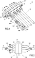
- the connector 10 includes a housing 20 and four cable tie assemblies 30A, 30B, 30C, 30D identical to each other.
- Each cable tie assembly includes a contact (32A, 32B, 32C, 32D), a spring (34A, 34B, 34C, 34D), and a sleeve (36A, 36B, 36C, 36D).
- the connector 10 constitutes a first connector designed to be fixed to a corresponding second connector 110 ( Fig. 2 ).
- the connector 10 can be connected to four cables 40.
- the connector 110 is on its side connected to four cables 140, the connectors 10 and 110 together make it possible to connect the four cables 40 to the four cables 140 in parallel.
- the cables 40 are assembled, away from the connector 10, in a sheath 41;
- the cables 140 are assembled, away from the connector 110, in a sheath 141.
- the box 20 is fixed to the box 120 by screws 44.
- connector 10 A relatively important difference between connector 10 and connector 110 is that in connector 10 the contacts are 'spring-loaded', whereas in connector 110 the contacts are fixed, i.e. maintained in a fixed position relative to the housing 120.
- the housing 20 is a housing made in two parts. It comprises an insert 21 made of injected and / or machined plastic, placed inside a shell 23 made of aluminum manufactured by machining ( Fig. 3 ). It has a platform 22, the ends of which are crossed by two screws 44 which serve to fix the connector 10 on the connector 110.
- the housing 20 has the general shape of a rectangular parallelepiped arranged between a front face 24 and a rear face 25.
- the rear face 25 is pierced by a wide opening serving to pass the fixing assemblies 30.
- the four fixing assemblies 30 being identical, the description of the connector 10 will be made simply by referring to the assembly 30A.
- Cable tie assembly 30A includes contact 32A, spring 34A, and sleeve 36A ( Fig. 1 , 3 ). It is used to fix the 40A cable to the box 20.
- the 40A cable consists of a single copper electrical conductor.
- the contact 32A is a contact also formed from copper by turning, and crimped at the end of the cable 40A.
- the front end 31A of the contact 32A is formed with four tabs 31A1,31A2,31A3,31A4 provided to fit inside a corresponding contact of the connector 110.
- the rear end 33A of the contact 32A has the shape of a sleeve, that is to say of a hollow cylinder.
- the internal bore is occupied by the end of the cable 40A, this cylindrical part 33A being precisely crimped onto the end of the cable.
- the spring 34A is disposed around the cylinder 33A.
- the contact 32A has a flange 35A.
- this flange On the rear side, this flange has a surface 37A, the normal of which is directed in the rear direction. This surface constitutes a contact spring bearing surface: it is on it that the front end of the spring 34A rests.
- the sleeve 36A has by definition the general shape of a hollow cylinder.
- the internal bore which passes through it in the direction of insertion (in the mounted position) has a first part, the diameter of which is slightly larger than the external diameter of the spring 34A, and which serves precisely to receive the spring 34A. Further back, this larger diameter bore portion extends to a smaller diameter bore portion, the diameter of which simply serves to pass the cable 40A with play.
- a spring bearing surface 38A is formed on which the rear end of the spring 34A rests.
- the outer surface of the sleeve 36A is illustrated in particular by the figure 1 . At its rear end, it comprises fins 39A which serve to hold the sleeve and in particular to rotate it when it is put in place, as will be described below.
- the outer surface of the sleeve 36A has two lugs 42 for axial locking.
- These lugs are arranged projecting on the outer surface of the sleeve 36A. They make it possible to prevent an axial displacement of the sleeve relative to the housing 20 towards the rear as follows.
- the shape of the housing 26 and of its opening is defined by its outer contour 27.
- the housing 26 is arranged so as to receive (in part) the contact fixing assemblies 30. It notably maintains the cylindrical parts of the sleeves. 36 by blocking all the degrees of freedom of these sleeves except for each the translation with respect to the axis of the fixing assembly of which it is part and the rotation about this axis. This maintenance is provided by cylindrical surfaces 49 arranged in the housing 26 which constitute the guide surfaces within the meaning of the invention.
- the diameter of the guide surfaces 49 is fixed so that the four sleeves 36 can pass into the contour 27 to fit into the housing 26.
- the lugs 42 can penetrate into the housing 26.
- the contour 27 has projecting parts 28 (most of them are in an arc) which project outwardly and allow the passage of the lugs 42.
- the interior of the housing 26 is provided so that the lugs 42 can penetrate inside the housing when a cable fixing assembly 30 is mounted in the housing 20.
- the connection of the mounting assemblies to the housing is of the bayonet type.
- the mounting of a cable fixing assembly 30, for example the assembly 30A, in the connector 10 is done by carrying out the following operations.
- a first step ( Figs. 3A, 3B and 3C ) the cable fixing assembly 30A is moved in translation along the insertion direction until the sleeve reaches a first insertion position in which the lugs 42A butt against a surface 29A of the housing. Throughout this translation, the sleeve remains in the angular insertion position. In this position, the lug 42A forms an angle ⁇ 1 with respect to the horizontal direction shown on the figure 3A .
- the sleeve 36 is then rotated by hand until it reaches the final angular position, illustrated in the figure. Fig. 4 (angle ⁇ 2). This rotational movement is blocked when the lugs 42A come into abutment against the internal wall of the housing 26 (arrow A, Fig. 5 ). Following this rotation, the lugs 42A are found placed, in view from the rear direction, at least partly behind a part 48 located at the rear 25 of the housing 20 and which is located opposite a part of the surface 29A .
- this part 48 of the housing 20 serves to prevent the sleeve 36 from retracting rearwardly, as will be shown in connection with the figures 5 and 6 .
- the connector 20 in fact comprises a latching mechanism which maintains the fixing assembly 30 in the mounted position.
- This latching mechanism consists mainly of the spring 34, and the various surfaces and structures which allow them to transmit their restoring force: towards the front, on the contact 32, the spring bearing surface 37; towards the rear, the spring bearing surfaces 38 formed on the sleeve, the axial locking pins 42 of the sleeve 36, cooperating with the part 48 of the housing 20.
- the locking step makes it possible to place the cable fixing assembly in the mounted position and to ensure the axial locking and the rotation locking of the sleeve 36, as follows.
- the sleeve 36A includes references 45A. These marks are constituted in this embodiment by short axial ribs protruding from the outer surface of the sleeve 36A. These axial ribs or references 45A extend rearwardly from the lugs 42A. In particular, in rear view (as seen on the Fig. 1 ) these references 45A fit inside the surface occupied by the pins 42A.
- markers 45A are inserted entirely inside the housing 26.
- the housing 26 is provided with grooves 50 arranged to allow the passage of the marks 45 as follows.
- the sleeve 36A is released. As the spring 34A exerts a rearward force on the sleeve 36A, the latter then moves back until the lugs 42A lock against an axial sleeve locking surface 47A provided inside the housing 26 on the sleeve. part 48 ( Fig. 6 ). The sleeve 36A is then axially locked in its final axial position (mounted position). Due to this backward movement (arrow B in the detail view of the figure 6 ), the marks 45A which until then were entirely inside the housing 20 protrude slightly from the latter, as can be seen for the marks 45B, 45C and 45D on the Fig. 1 . The operator who is in the process of mounting the cable fixing assembly 30A can thus check that the sleeve 36A which he has just fitted has positioned itself correctly.
- the marks 45 provide not only an assembly indicator function, but also a rotation locking function. Indeed, during the retraction of the sleeve 36A to reach the final axial position, the marks 45A are introduced into the corresponding grooves 50 arranged inside the housing 26 to accommodate them. These grooves match (with clearance) the external shape of the reference marks 45A and consequently, prevent any rotation of the sleeve 36A. The sleeve 36A is thus prevented from rotating, for example as a result of vibrations, to find itself in the angular position reached at the end of the first assembly step (angle ⁇ 1) in which the sleeve 36A could possibly come out of the housing 26.
- the various figures clearly show the compactness of the connector 10.
- the fixing assemblies 30 are all inserted via a single opening, delimited on the rear face 25 of the housing 26 by its outline 27.
- the parts of the sleeves 36 closest to each other are directly opposite each other, that is to say more precisely are not separated by any partition of the housing 20. Thanks to to this, the center distance d between the sleeves 36 can be reduced to a very low value, in particular a value less than 1.2 D where D is the outside diameter of the sleeves 36.
Description
L'invention concerne un connecteur pour la connexion d'au moins deux câbles à au moins deux câbles correspondants. Chaque câble peut ici comporter un ou plusieurs conducteurs électriques, et/ou un ou plusieurs conducteurs de lumière, c'est-à-dire une ou des fibres optiques.The invention relates to a connector for connecting at least two cables to at least two corresponding cables. Each cable can here include one or more electrical conductors, and / or one or more light conductors, that is to say one or more optical fibers.
Plus précisément, le connecteur constitue un premier connecteur qui est configuré pour être lui-même fixé à un deuxième connecteur. Lesdits au moins deux câbles sont fixés audit premier connecteur et lesdits au moins deux câbles correspondants sont fixés au deuxième connecteur. Aussi, lorsque l'on assemble ensemble le premier et le deuxième connecteur, on connecte ensemble lesdits au moins deux câbles avec lesdits aux moins deux câbles correspondants.More precisely, the connector constitutes a first connector which is configured to be itself fixed to a second connector. Said at least two cables are attached to said first connector and said at least two corresponding cables are attached to the second connector. Also, when the first and the second connector are assembled together, said at least two cables are connected together with said at least two corresponding cables.
Différents types de connecteurs pour connecter des câbles sont connus, par exemple par les documents
Il existe de plus de nombreux types de connecteurs pour connecter ensemble au moins deux câbles, de la manière indiquée ci-dessus.In addition, there are many types of connectors for connecting two or more cables together, as shown above.
Il existe notamment un connecteur comprenant un boîtier, et plusieurs ensembles de fixation de câble. Les différents ensembles de fixation de câble sont tous identiques. Chaque ensemble de fixation de câble sert à fixer l'un des câbles au boîtier. Tous les câbles sont fixés au boîtier via la face arrière de celui-ci.There is in particular a connector comprising a housing, and several cable fixing assemblies. The different cable tie sets are all the same. Each cable tie assembly is used to secure one of the cables to the enclosure. All cables are attached to the housing via the rear face thereof.
Aussi, pour permettre la fixation des ensembles de fixation de câble, le boîtier présente des ouvertures dans sa face arrière, à savoir autant d'ouvertures qu'il y a de câbles à fixer.Also, to allow the fixing of the cable fixing assemblies, the box has openings in its rear face, namely as many openings as there are cables to be fixed.
Chaque ensemble de fixation de câble comprend un contact, un ressort, et un manchon.Each cable tie assembly includes a contact, a spring, and a sleeve.
Le contact est une pièce (ou un ensemble de pièces) d'extrémité, fixé à l'extrémité du câble pour assurer la connexion avec un contact correspondant d'un autre ensemble de fixation avec lequel l'ensemble de fixation considéré doit être connecté.The contact is an end part (or a set of parts), attached to the end of the cable to ensure connection with a corresponding contact of another fixing assembly with which the fixing assembly in question is to be connected.
Dans le connecteur, considéré ici comme étant le premier connecteur en faisant référence à l'explication donnée précédemment, la fonction du contact est définie en liaison avec le contact correspondant du deuxième connecteur : le contact est une pièce (ou un ensemble de pièces) de terminaison, qui est apte, en coopérant avec le contact correspondant du deuxième connecteur, à établir la connexion entre le ou les conducteurs électriques ou de lumière du câble et le ou les conducteurs électriques ou de lumière du câble correspondant fixé au deuxième connecteur.In the connector, considered here as being the first connector with reference to the explanation given previously, the function of the contact is defined in connection with the corresponding contact of the second connector: the contact is a terminating part (or a set of parts), which is able, by cooperating with the corresponding contact of the second connector, to establish the connection between the electrical conductor (s) or of cable light and the corresponding electrical or light conductor (s) of the cable attached to the second connector.
Au sein de chaque ensemble de fixation de câble, chaque contact est configuré pour être fixé à une extrémité de l'un des câbles préalablement passé à travers le manchon, et pour être alors monté suivant une direction d'insertion en passant à travers l'une des ouvertures de la face arrière du boîtier. La direction d'insertion est la même pour tous les ensembles de fixation de câble.Within each cable attachment assembly, each contact is configured to be attached to one end of one of the cables previously passed through the sleeve, and then to be mounted in an insertion direction by passing through one of the openings in the rear face of the housing. The direction of insertion is the same for all cable tie assemblies.
Les connecteurs de ce type assurent la fonction de connexion de manière très satisfaisante ; cependant, ils ne sont pas très compacts, ce qui peut poser problème pour certaines applications.Connectors of this type perform the connection function very satisfactorily; however, they are not very compact, which can be problematic for some applications.
Aussi, l'objectif de l'invention est de proposer un connecteur (un 'premier connecteur') auquel un certain nombre de câbles peuvent être fixés de manière à être connectés à un même nombre de câbles correspondants par l'intermédiaire d'un deuxième connecteur, et qui présente une compacité accrue par rapport au connecteur indiqué précédemment.Also, the objective of the invention is to provide a connector (a 'first connector') to which a number of cables can be attached so as to be connected to the same number of corresponding cables by means of a second connector, and which has increased compactness compared to the connector indicated above.
Cet objectif est atteint grâce à un connecteur selon la revendication 1.This objective is achieved by means of a connector according to
De plus, lorsque le connecteur est monté, le premier et le deuxième ensemble de fixation de câble (et éventuellement d'autres ensembles de fixation de câble) sont placés au moins en partie dans le même logement. L'expression 'dans le même logement' signifie ici que les parties du logement dans lesquelles sont disposées les parties du premier et du deuxième ensemble de fixation de contact qui sont dans le boîtier communiquent, c'est-à-dire ne sont pas entièrement séparées l'une de l'autre par une cloison. Par conséquent, en position montée dans le boîtier, les parties du premier et du deuxième ensemble de fixation de contact qui sont dans le boîtier sont au moins en partie l'une en face de l'autre. Ainsi, généralement les portions du premier et du deuxième ensemble de fixation de câble les plus proches l'une de l'autre se trouvent directement en regard l'une de l'autre.In addition, when the connector is mounted, the first and second cable fixing assemblies (and possibly other cable fixing assemblies) are placed at least in part in the same housing. The expression 'in the same housing' means here that the parts of the housing in which the parts of the first and of the second contact fastening assembly which are in the housing are disposed communicate, that is to say are not entirely separated from each other by a partition. Therefore, in the mounted position in the housing, the parts of the first and second contact fastening assemblies which are in the housing are at least partly opposite each other. Thus, generally the portions of the first and of the second cable fixing assembly closest to one another are located directly opposite one another.
Le premier et le deuxième ensemble de fixation de câble peuvent être placés extrêmement près l'un de l'autre. Grâce à ces dispositions, le boîtier du connecteur peut être de taille réduite, l'entraxe entre les ensembles de fixation de câble peut être faible, et le connecteur peut être compact.The first and second cable tie assemblies can be placed extremely close to each other. Thanks to these arrangements, the housing of the connector can be reduced in size, the center distance between the cable fixing assemblies can be small, and the connector can be compact.
Le connecteur défini précédemment comprend au moins deux ensembles de fixation de câbles et peut naturellement en comprendre un nombre quelconque strictement supérieur à deux.The connector defined above comprises at least two cable fixing assemblies and can naturally include any number strictly greater than two.
Le contact a la même fonction que le contact du connecteur présenté auparavant dans la section 'Arrière-plan de l'invention'.The contact has the same function as the connector contact presented previously in the 'Background to the invention' section.
Chaque câble peut être un câble comprenant un ou plusieurs conducteurs électriques et/ou une ou plusieurs fibres optiques. Par conséquent, chaque contact peut être un contact prévu pour un ou plusieurs conducteurs électriques et/ou une ou plusieurs fibres optiques.Each cable can be a cable comprising one or more electrical conductors and / or one or more optical fibers. Consequently, each contact can be a contact provided for one or more electrical conductors and / or one or more optical fibers.
Bien que seule l'ouverture du logement interne du boîtier en face arrière ait été mentionnée ci-dessus, le logement interne présente naturellement en outre au moins une autre ouverture pour la connexion des contacts des ensembles de fixation, normalement vers l'avant.Although only the opening of the internal housing of the housing on the rear face has been mentioned above, the internal housing naturally also has at least one other opening for the connection of the contacts of the fixing assemblies, normally towards the front.
Le boîtier peut être réalisé en une ou plusieurs parties.The housing can be made in one or more parts.
Lorsque les différentes surfaces externes de l'ensemble de fixation de câble, notamment les surfaces périphériques externes des contacts, sont en matériau isolant, le logement des ensembles de fixation peut être en matériau conducteur, par exemple en métal ; le boîtier peut être par exemple constitué par une seule pièce métallique, notamment usinée. Cela peut être le cas par exemple si les contacts présentent une gaine extérieure isolante.When the various external surfaces of the cable fixing assembly, in particular the external peripheral surfaces of the contacts, are made of an insulating material, the housing of the fixing assemblies can be made of a conductive material, for example metal; the housing may for example be constituted by a single metal part, in particular machined. This may be the case, for example, if the contacts have an insulating outer sheath.
Inversement, au cas où l'extérieur des contacts est en matériau conducteur, notamment métallique, et plus particulièrement lorsqu'un signal ou de l'énergie est transmis par ce matériau, les contacts doivent être isolés électriquement les uns des autres dans le connecteur. Dans ce cas, de préférence le logement est formé en matériau isolant électriquement, par exemple en matière plastique (polymère ou autre).Conversely, in the case where the outside of the contacts is made of a conductive material, in particular metallic, and more particularly when a signal or energy is transmitted by this material, the contacts must be electrically isolated from each other in the connector. In this case, the housing is preferably formed of an electrically insulating material, for example of plastic (polymer or other).
Le boîtier peut alors par exemple être formé par un insert isolant placé à l'intérieur d'une coque extérieure métallique. Il peut sinon éventuellement être entièrement réalisé en matière plastique.The housing can then for example be formed by an insulating insert placed inside a metallic outer shell. If not, it can optionally be entirely made of plastic.
Le montage au moins du premier et du deuxième ensembles de fixation de câble dans le boîtier est fait grâce aux connexions baïonnette prévues à cet effet. Une connexion baïonnette est un agencement ou une configuration spécifique de deux pièces permettant d'assembler celles-ci en réalisant deux mouvements, à savoir un mouvement de translation relative d'une pièce par rapport à l'autre suivi par un mouvement de rotation relative d'une pièce par rapport à l'autre. Une connexion baïonnette peut aussi être appelée connexion 'quart de tour'. Le terme 'quart de tour' n'implique en aucune manière ici que la rotation soit égale à un quart de tour. La rotation peut être comprise entre 20 et 45°, par exemple.The mounting of at least the first and the second cable fixing assemblies in the housing is made by means of the bayonet connections provided for this purpose. A bayonet connection is a specific arrangement or configuration of two parts making it possible to assemble them by carrying out two movements, namely a relative translational movement of one part with respect to the other followed by a relative rotational movement of 'one piece in relation to the other. A bayonet connection can also be referred to as a 'quarter turn' connection. The term 'quarter turn' in no way implies here that the rotation is equal to a quarter turn. The rotation can be between 20 and 45 °, for example.
On comprend donc que dans le connecteur, du fait des connexions baïonnette, chacun desdits premier et deuxième ensemble de fixation de câble est configuré pour être monté en insérant l'ensemble de fixation de câble axialement dans l'ouverture du boîtier jusqu'à une certaine position axiale prédéterminée, puis en faisant tourner le manchon autour de l'axe de l'ensemble de fixation.It is therefore understood that in the connector, due to the bayonet connections, each of said first and second cable fixing assembly is configured to be mounted by inserting the cable fixing assembly axially into the opening of the housing up to a certain point. predetermined axial position, then rotating the sleeve around the axis of the fastener assembly.
Le montage de l'ensemble de fixation au moins en partie dans le logement interne du boîtier a pour but et pour effet de fixer l'ensemble de fixation au boîtier. Par sécurité, des moyens supplémentaires peuvent être prévus pour assurer que l'ensemble de fixation reste durablement dans la position de montage voulue et ne se démonte pas au fil du temps.The purpose and effect of mounting the fastening assembly at least in part in the internal housing of the housing is to secure the fastening assembly to the housing. For safety, additional means can be provided to ensure that the fixing assembly remains durably in the desired mounting position and does not come apart over time.
Dans ce but, dans un mode de réalisation le connecteur comprend, pour au moins un desdits premier et deuxième ensemble de fixation de câble, un mécanisme d'encliquetage (ou clipsage) permettant à l'ensemble de fixation de câble, à l'issue du montage, d'être verrouillé en position montée, et ainsi d'être maintenu en position fixe par rapport au boîtier. L'encliquetage (ou clipsage) est un mode d'assemblage de deux parties par engagement et déformation élastique (en général déformation locale, par exemple d'une languette, ou par déformation de l'ensemble des pièces impliquées dans l'assemblage). Lorsque les deux parties sont engagées dans la position d'encliquetage, les parties ont généralement repris leur forme initiale et ne présentent plus de déformation élastique (ou une déformation élastique moindre). Lorsque les deux parties sont engagées l'une avec l'autre dans la position d'encliquetage, elles coopèrent l'une avec l'autre de manière à s'opposer, voire bloquer, les mouvements relatifs desdites pièces dans le sens du dégagement (sens opposé au sens de l'engagement).For this purpose, in one embodiment the connector comprises, for at least one of said first and second cable fixing assembly, a latching mechanism (or clipping) allowing the cable fixing assembly, after assembly, to be locked in the mounted position, and thus to be kept in a fixed position relative to the housing. Snap-fastening (or clipping) is a method of assembling two parts by engagement and elastic deformation (generally local deformation, for example of a tongue, or by deformation of all the parts involved in the assembly). When the two parts are engaged in the snap-in position, the parts have generally returned to their initial shape and no longer exhibit elastic deformation (or less elastic deformation). When the two parts are engaged with each other in the latching position, they cooperate with each other so as to oppose, or even block, the relative movements of said parts in the direction of release ( opposite to the sense of engagement).
Ainsi par exemple, dans un mode de réalisation chacun des premier et deuxième ensemble de fixation de câble est configuré pour être monté dans le boîtier en insérant l'ensemble de fixation de câble dans l'ouverture du boîtier jusqu'à une première position axiale, puis en faisant tourner le manchon autour de l'axe de l'ensemble de fixation, puis en relâchant le manchon, l'ensemble de fixation de câble venant alors se bloquer axialement par rapport au boîtier sous l'action de moyens de rappel. Ces moyens de rappel peuvent par exemple être un ressort.Thus for example, in one embodiment each of the first and second cable attachment assemblies is configured to be mounted in the housing by inserting the cable attachment assembly into the opening of the housing to a first axial position, then by rotating the sleeve around the axis of the fixing assembly, then by releasing the sleeve, the cable fixing assembly then locking axially with respect to the housing under the action of return means. These return means can for example be a spring.
Par ailleurs, à l'issue du montage, le boîtier et le manchon peuvent être agencés de différentes manières pour assurer la fixation de l'ensemble de fixation de câble au boîtier.Furthermore, after assembly, the housing and the sleeve can be arranged in different ways to secure the attachment of the cable fixing assembly to the housing.
De préférence, mais en particulier pour des connexions par rotation-translation, on peut prévoir de premiers moyens de maintien pour assurer le blocage de tous les degrés de liberté du manchon (par rapport au boîtier) sauf une translation par rapport à l'axe de l'ensemble de fixation et une rotation autour de cet axe, ainsi que de deuxièmes et troisièmes moyens de maintien pour assurer le blocage du manchon respectivement en translation suivant la direction d'insertion et en rotation autour de cet axe.Preferably, but in particular for connections by rotation-translation, one can provide first holding means to ensure the locking of all the degrees of freedom of the sleeve (relative to the housing) except a translation relative to the axis of the fixing assembly and a rotation around this axis, as well as second and third holding means to ensure the locking of the sleeve respectively in translation in the direction of insertion and in rotation around this axis.
Pour réaliser les premiers moyens de maintien, dans un mode de réalisation, pour chacun desdits premier et deuxième ensemble de fixation de câble :
- la connexion baïonnette comporte au moins une surface de guidage formée dans le boîtier ; et
- l'ensemble de fixation de câble et le boîtier sont agencés de telle sorte que lorsque l'ensemble de fixation de câble est monté au moins en partie dans le logement interne du boîtier, ladite au moins une surface de guidage coopère avec le manchon de manière à bloquer tous les degrés de liberté du manchon sauf une translation par rapport à l'axe de l'ensemble de fixation et une rotation autour de cet axe. La ou les surfaces de guidage constituent donc les premiers moyens de maintien. La ou les surface(s) de guidage peuvent notamment être des surfaces d'un cylindre à base circulaire.
- the bayonet connection has at least one guide surface formed in the housing; and
- the cable fixing assembly and the housing are arranged such that when the cable fixing assembly is mounted at least in part in the internal housing of the housing, said at least one guide surface cooperates with the sleeve so in blocking all the degrees of freedom of the sleeve except a translation relative to the axis of the fixing assembly and a rotation about this axis. The guide surface or surfaces therefore constitute the first holding means. The guide surface (s) can in particular be surfaces of a cylinder with a circular base.
Dans ce mode de réalisation, pour chaque ensemble de fixation de câble, la fixation du câble est assurée en grande partie par la ou les surfaces de guidage. Ces surfaces permettent de bloquer (cependant éventuellement avec une certaine tolérance, un certain jeu) tous les degrés de liberté du manchon sauf la translation par rapport à l'axe de l'ensemble de fixation et une rotation autour de cet axe. Le plus souvent, le manchon est de forme extérieure cylindrique. La ou les surfaces de guidage ont une forme également cylindrique, de diamètre au moins égal à celui du manchon, ce qui permet d'assurer que le manchon est disposé de manière coaxiale aux surfaces de guidage et d'assurer ainsi le maintien en position du manchon (hormis sa translation axiale et sa rotation par rapport à l'axe de l'ensemble de fixation).In this embodiment, for each cable fixing assembly, the fixing of the cable is ensured largely by the guide surface (s). These surfaces make it possible to block (however possibly with a certain tolerance, a certain play) all the degrees of freedom of the sleeve except the translation with respect to the axis of the fixing assembly and a rotation about this axis. Most often, the sleeve is of cylindrical outer shape. The guide surface (s) also have a cylindrical shape, with a diameter at least equal to that of the sleeve, which makes it possible to ensure that the sleeve is arranged coaxially with the guide surfaces and thus to ensure that the sleeve is held in position (apart from its axial translation and its rotation with respect to the axis of the fixing assembly) .
La particularité du connecteur selon l'invention est que, contrairement au connecteur présenté auparavant, au moins pour les deux ensembles de fixation de câble, les contacts sont configurés pour être montés suivant la direction d'insertion en passant à travers la même ouverture de la face arrière du boîtier. Dans le mode de réalisation présenté précédemment dans lequel le boîtier présente une ou des surfaces de guidage, de préférence, au niveau axialement de ladite au moins une surface de guidage, au moins pour lesdits premier et deuxième ensemble de fixation de câble, ladite au moins une surface de guidage de l'ensemble de fixation de câble considéré ne s'étend que sur une partie de la périphérie du manchon, et laisse des portions des manchons du premier et du deuxième ensemble de fixation de câble les plus proches l'une de l'autre directement en regard l'une de l'autre, ces portions des manchons du premier et du deuxième ensemble de fixation de câble n'étant séparées l'une de l'autre par aucune cloison du boîtier.The peculiarity of the connector according to the invention is that, unlike the connector presented previously, at least for the two cable fixing assemblies, the contacts are configured to be mounted in the direction of insertion by passing through the same opening of the cable. rear side of the housing. In the embodiment presented above in which the housing has one or more guide surfaces, preferably at the level axially of said at least one guide surface, at least for said first and second cable fixing assembly, said at least a guide surface of the cable fixing assembly in question extends only over a part of the periphery of the sleeve, and leaves portions of the sleeves of the first and of the second cable fixing assembly closest to one of the other directly opposite one another, these portions of the sleeves of the first and of the second cable fixing assembly not being separated from each other by any partition of the housing.
Cet agencement permet de positionner les contacts du premier et du deuxième ensemble de fixation de câble, au sein du logement du boîtier, très près l'un de l'autre. Grâce à cet agencement, l'entraxe entre les deux ensembles de fixation, en position montée, peut être réduit au minimum ; notamment, les manchons des deux ensembles de fixation en position montée peuvent n'être séparés que par une distance très faible ; il n'est pas nécessaire de prévoir une distance minimum, comme ce serait le cas si une paroi du boîtier devait séparer les deux manchons l'un de l'autre.This arrangement makes it possible to position the contacts of the first and of the second cable fixing assembly, within the housing of the housing, very close to one another. Thanks to this arrangement, the center distance between the two fixing assemblies, in the mounted position, can be reduced to a minimum; in particular, the sleeves of the two fixing assemblies in the mounted position may be separated only by a very small distance; it is not necessary to provide a minimum distance, as would be the case if a wall of the housing were to separate the two sleeves from each other.
L'entraxe entre le premier et le deuxième ensemble de fixation de câble peut par suite être inférieur à 1,5 fois, voire 1,2 fois le diamètre externe du manchon (ce diamètre externe concerne la partie du manchon qui se trouve dans le boîtier en position montée, et qui coopère avec la ou les surfaces de guidage. Le manchon peut comporter une partie située hors du boîtier en position montée ; cette partie peut être de forme quelconque, notamment de forme non cylindrique).The center distance between the first and the second cable fixing assembly can therefore be less than 1.5 times or even 1.2 times the external diameter of the sleeve (this external diameter relates to the part of the sleeve which is located in the housing in the mounted position, and which cooperates with the guide surface (s). The sleeve may include a part located outside the housing in the mounted position; this part may be of any shape, in particular of non-cylindrical shape).
Dans un mode de réalisation de l'invention, en vue suivant la direction d'insertion, au moins pour un desdits ensembles de fixation de câble, ladite au moins une surface de guidage s'étend (éventuellement, s'étend uniquement) sur deux secteurs angulaires opposés l'un à l'autre.In one embodiment of the invention, seen in the direction of insertion, at least for one of said cable fixing assemblies, said at least one guide surface extends (possibly extends only) over two angular sectors opposite to each other.
De préférence, ces deux secteurs angulaires sont orientés dans des directions globalement perpendiculaires ou obliques par rapport à la droite passant par les axes du premier et du deuxième ensemble de fixation de câbles. Un tel mode de réalisation est choisi notamment lorsque le connecteur comporte trois ensemble de fixation de câble, et lorsque ces trois ensembles de fixation de câble sont placés juste à côté les uns des autres en position montée (alignés). Pour l'ensemble de fixation de câble placé entre les deux autres (en position montée), le boîtier présente alors exactement deux surfaces de guidage situées en vis-à-vis l'une de l'autre et entre lesquelles se trouve le manchon, en position montée.Preferably, these two angular sectors are oriented in directions which are generally perpendicular or oblique with respect to the line passing through the axes. of the first and second cable fixing assembly. Such an embodiment is chosen in particular when the connector comprises three fixing assemblies of cable, and when these three cable tie assemblies are placed right next to each other in the mounted position (aligned). For the cable fixing assembly placed between the other two (in the mounted position), the box then has exactly two guide surfaces located opposite one another and between which the sleeve is located, in the mounted position.
Par ailleurs, pour assurer le blocage axial du contact dans le boîtier, le connecteur peut être agencé de différentes manières.Furthermore, to ensure the axial locking of the contact in the housing, the connector can be arranged in different ways.
Les deuxièmes moyens de maintien peuvent notamment comporter un ressort, qui forme un mécanisme d'encliquetage. En complément de la ou des surfaces de guidage, la fixation de l'ensemble de fixation de câble est alors assurée par la coopération du boîtier, du ressort et du contact avec le manchon. Le ressort est généralement du type hélicoïdal et est alors placé autour de l'extrémité du câble. Dans un mode de réalisation, le ressort est au moins en partie, ou éventuellement entièrement disposé à l'intérieur du manchon, lorsque l'ensemble de fixation est en position montée.The second retaining means may in particular include a spring, which forms a latching mechanism. In addition to the guide surface (s), the fixing of the cable fixing assembly is then ensured by the cooperation of the housing, the spring and the contact with the sleeve. The spring is generally of the helical type and is then placed around the end of the cable. In one embodiment, the spring is at least partly, or possibly entirely, disposed inside the sleeve, when the fixing assembly is in the mounted position.
Le ressort est utilisé en compression. En position montée, il applique des forces inverses respectivement sur le boîtier et sur le contact, ce qui conduit le contact à être poussé vers l'avant (c'est-à-dire dans la direction d'insertion) par rapport au boîtier. Le boîtier est agencé de manière à bloquer axialement le contact.The spring is used in compression. In the mounted position, it applies opposite forces to the housing and the contact respectively, which causes the contact to be pushed forward (i.e. in the direction of insertion) relative to the housing. The housing is arranged so as to axially block the contact.
Ainsi dans un mode de réalisation, pour au moins un desdits premier et deuxième ensemble de fixation de câble :
- le mécanisme d'encliquetage comprend un ressort ;
- le contact est configuré pour, après avoir été fixé à l'extrémité du câble préalablement passé à travers le manchon, être monté dans une direction d'insertion suivant l'axe de l'ensemble de fixation en passant à travers l'ouverture de la face arrière du boîtier ;
- l'ensemble de fixation de câble et le boîtier sont agencés de telle sorte que lorsque l'ensemble de fixation de câble est en position montée, le ressort est comprimé, et, en prenant appui sur le boîtier, appuie sur le contact suivant la direction d'insertion, et par suite bloque axialement le contact par rapport au boîtier suivant la direction d'insertion.
- the ratchet mechanism includes a spring;
- the contact is configured so, after having been fixed to the end of the cable previously passed through the sleeve, to be mounted in an insertion direction along the axis of the fixing assembly passing through the opening of the rear face of the housing;
- the cable fixing assembly and the housing are arranged such that when the cable fixing assembly is in the mounted position, the spring is compressed, and, resting on the housing, presses on the contact in the direction insertion, and therefore axially blocks the contact with respect to the housing in the direction of insertion.
Pour permettre que le ressort appuie sur le contact suivant la direction d'insertion, dans un mode de réalisation le contact présente une surface d'appui de ressort du contact disposée de telle sorte que le ressort disposé autour de l'extrémité du câble puisse appliquer une force de compression à la surface d'appui de ressort du contact suivant une direction axiale de celui-ci. En particulier, dans un mode de réalisation, pour au moins un ensemble de fixation de contact le contact a une forme extérieure sensiblement cylindrique, et la surface d'appui de ressort du contact est formée sur une bride externe du contact.To allow the spring to press against the contact in the direction of insertion, in one embodiment the contact has a spring bearing surface of the contact disposed such that the spring disposed around the end of the cable can apply. a compressive force at the spring bearing surface of the contact in an axial direction thereof. In particular, in one embodiment, for at least one contact attachment assembly the contact has a shape substantially cylindrical outer, and the spring bearing surface of the contact is formed on an outer flange of the contact.
D'autre part, en ce qui concerne l'appui du ressort sur le boîtier, cet appui peut être direct (le ressort est en contact avec le boîtier) ou indirect. Dans ce dernier cas, par exemple le ressort peut être en appui sur le manchon, et le manchon est en appui sur le boîtier. Pour permettre cet appui, dans un mode de réalisation le manchon présente une surface d'appui de ressort du manchon disposée de telle sorte que le ressort disposé autour de l'extrémité du câble puisse appliquer une force de compression à la surface d'appui de ressort du manchon suivant une direction axiale de celui-ci.On the other hand, as regards the support of the spring on the housing, this support can be direct (the spring is in contact with the housing) or indirect. In the latter case, for example the spring can be supported on the sleeve, and the sleeve is supported on the housing. To allow this support, in one embodiment the sleeve has a spring bearing surface of the sleeve arranged so that the spring disposed around the end of the cable can apply a compressive force to the bearing surface of the sleeve. spring from the sleeve in an axial direction thereof.
Dans ce but, dans un mode de réalisation le manchon présente un alésage intérieur cylindrique et la surface d'appui de ressort du manchon est formée sur un épaulement agencé dans cet alésage.For this purpose, in one embodiment the sleeve has a cylindrical internal bore and the spring bearing surface of the sleeve is formed on a shoulder arranged in this bore.
Il faut noter que dans certains modes de réalisation, le connecteur assure le blocage axial du contact de deux manières différentes selon qu'il est connecté ou non avec un 'deuxième connecteur' correspondant.It should be noted that in certain embodiments, the connector ensures the axial locking of the contact in two different ways depending on whether or not it is connected with a corresponding 'second connector'.
Selon un premier mode de blocage, en l'absence du 'deuxième connecteur' cité auparavant, c'est le boîtier lui-même qui bloque le contact vers l'avant, en contrant la force appliquée au contact par le ressort. (Le contact se bloque vers l'avant contre une surface du boîtier).According to a first blocking mode, in the absence of the 'second connector' mentioned above, it is the housing itself which blocks the contact towards the front, by countering the force applied to the contact by the spring. (The contact locks forward against a surface of the housing).
Inversement, lorsque le connecteur (considéré comme étant un premier connecteur) est fixé au deuxième connecteur, le blocage axial des contacts vers l'avant se fait de manière différente : les contacts du premier connecteur et du deuxième connecteur sont alors engagés en prise mutuelle. Avantageusement, dans cette position le blocage axial de chacun des contacts du premier et du deuxième connecteur est alors assuré non pas par le boîtier bloquant le contact, mais par les contacts du deuxième connecteur engageant le contact du premier connecteur. Les ressorts des ensembles de fixation de contact servent alors à maintenir les contacts du premier connecteur en contact permanent avec les contacts du deuxième connecteur. Grâce à cela, avantageusement un contact de très bonne qualité est établi entre les contacts du premier et du deuxième connecteur. Le contact est alors un contact à fonction ressort intégrée.Conversely, when the connector (considered to be a first connector) is fixed to the second connector, the axial locking of the contacts towards the front takes place in a different manner: the contacts of the first connector and of the second connector are then engaged in mutual engagement. Advantageously, in this position the axial locking of each of the contacts of the first and of the second connector is then ensured not by the housing blocking the contact, but by the contacts of the second connector engaging the contact of the first connector. The springs of the contact fastening assemblies then serve to maintain the contacts of the first connector in permanent contact with the contacts of the second connector. Thanks to this, advantageously a very good quality contact is established between the contacts of the first and of the second connector. The contact is then a contact with integrated spring function.
Dans un mode de réalisation du connecteur selon l'invention, la force appliquée par le ressort au boîtier vers l'arrière est transmise via le manchon : la partie arrière du ressort exerce une force vers l'arrière sur le manchon, et le manchon à son tour exerce cette force sur le boîtier. Le manchon doit donc pouvoir transmettre cette force au boîtier.In one embodiment of the connector according to the invention, the force applied by the spring to the housing towards the rear is transmitted via the sleeve: the rear part of the spring exerts a force towards the rear on the sleeve, and the sleeve to his turn exercises this force on the housing. The sleeve must therefore be able to transmit this force to the housing.
Dans ce but, dans un mode de réalisation préférentiel, le manchon présente au moins un ergot de blocage axial, agencé en saillie sur sa surface externe ; etFor this purpose, in a preferred embodiment, the sleeve has at least one axial locking lug, protruding from its outer surface; and
le boîtier et l'ensemble de fixation de câble considéré sont configurés de telle sorte qu'en position montée, sous l'effet de la pression du ressort, le manchon est poussé vers l'arrière dans la position montée dans laquelle ledit au moins un ergot de blocage axial est en appui sur au moins une surface de blocage axial de manchon du boîtier, qui bloque ledit au moins un ergot de blocage axial vers l'arrière et empêche ainsi tout déplacement du manchon vers l'arrière.the housing and the cable fixing assembly in question are configured such that in the mounted position, under the effect of the pressure of the spring, the sleeve is pushed backwards into the mounted position in which said at least one axial locking lug bears on at least one axial locking surface of the sleeve of the housing, which blocks said at least one axial locking lug towards the rear and thus prevents any displacement of the sleeve towards the rear.
Dans une variante préférentielle, le manchon de l'ensemble de fixation de câble considéré et le boîtier sont configurés de telle sorte que :
- le manchon, placé dans une première position angulaire, peut être introduit dans le logement du boîtier suivant la direction d'insertion, puis
- le manchon peut être alors amené à tourner autour de l'axe de l'ensemble de fixation pour atteindre une deuxième position angulaire, dans laquelle ladite au moins une surface de blocage axial de manchon du boîtier bloque ledit au moins un ergot de blocage axial vers l'arrière.
- le manchon de l'ensemble de fixation de câble considéré, placé dans une première position angulaire, peut être introduit (au moins en partie) dans le logement du boîtier suivant la direction d'insertion (il atteint alors une première position axiale), puis
- le manchon peut être alors amené à tourner autour de l'axe de l'ensemble de fixation pour atteindre une deuxième position angulaire dans laquelle une surface de blocage axial de manchon du boîtier bloque ledit au moins un ergot de blocage axial (et par conséquent le manchon) vers l'arrière, et empêche ainsi tout déplacement du manchon vers l'arrière.
- the sleeve, placed in a first angular position, can be introduced into the housing of the housing in the direction of insertion, then
- the sleeve can then be caused to rotate about the axis of the fixing assembly to reach a second angular position, in which said at least one axial locking surface of the sleeve of the housing locks said at least one axial locking lug towards the back.
- the sleeve of the cable fixing assembly considered, placed in a first angular position, can be introduced (at least in part) into the housing of the housing in the direction of insertion (it then reaches a first axial position), then
- the sleeve can then be caused to rotate about the axis of the fixing assembly to reach a second angular position in which an axial locking surface of the sleeve of the housing blocks said at least one axial locking lug (and therefore the sleeve) backwards, and thus prevents any displacement of the sleeve backwards.
Enfin, pour assurer le blocage en rotation du manchon par rapport au boîtier, il est préférable de prévoir également les troisièmes moyens de maintien mentionnés précédemment.Finally, to ensure that the sleeve is locked in rotation with respect to the housing, it is preferable to also provide the third holding means mentioned above.
Dans ce but, dans un mode de réalisation, au moins pour un ensemble de fixation de câble considéré, le manchon de l'ensemble de fixation de câble considéré et le boîtier sont configurés de telle sorte que :
- le boîtier présente au moins une surface de blocage en rotation, qui n'est pas de révolution autour de la direction d'insertion ; et
- le manchon présente au moins un ergot anti-rotation, agencé en saillie sur sa surface externe.
- the housing has at least one rotation blocking surface, which is not of revolution around the direction of insertion; and
- the sleeve has at least one anti-rotation lug, protruding from its outer surface.
De plus, l'ensemble de fixation de câble considéré et le boîtier sont alors agencés de telle sorte que lors du montage de l'ensemble de fixation de câble considéré au moins en partie dans le logement interne du boîtier :
- l'ensemble de fixation de câble est introduit dans le logement du boîtier suivant la direction d'insertion par l'ouverture du boîtier jusqu'à ce que le manchon atteigne axialement une première position axiale, et angulairement, une première position angulaire ; puis
- le manchon tourne alors autour de l'axe de l'ensemble de fixation pour atteindre une deuxième position angulaire ;
- le manchon coulisse alors axialement par rapport au boîtier pour atteindre une deuxième position axiale située en arrière de la première position axiale ; et
- lorsque le manchon est dans la deuxième position axiale, l'ergot anti-rotation coopère avec ladite au moins une surface de blocage en rotation de manière à empêcher une rotation du manchon autour de l'axe de l'ensemble de fixation.
- the cable fixing assembly is introduced into the housing of the housing in the direction of insertion through the opening of the housing until the sleeve axially reaches a first axial position, and angularly, a first angular position; then
- the sleeve then rotates around the axis of the fixing assembly to reach a second angular position;
- the sleeve then slides axially relative to the housing to reach a second axial position situated behind the first axial position; and
- when the sleeve is in the second axial position, the anti-rotation lug cooperates with said at least one rotation blocking surface so as to prevent rotation of the sleeve around the axis of the fixing assembly.
Enfin, le connecteur peut présenter avantageusement des repères visuels (un repère par ensemble de fixation de câble) afin de permettre de s'assurer que les différents câbles sont convenablement fixés au boîtier.Finally, the connector can advantageously have visual marks (one mark per cable fixing assembly) in order to make it possible to ensure that the various cables are properly fixed to the box.
Ainsi dans un mode de réalisation, au moins pour l'ensemble de fixation de câble considéré, le manchon comporte un repère, l'ensemble de fixation de câble et le manchon sont configurés de telle sorte que lorsque le manchon est dans la première position axiale, le repère n'est pas visible sur un côté arrière du boîtier, alors que lorsque le manchon est dans la deuxième position axiale, le repère est visible, et de préférence dépasse, sur le côté arrière du boîtier. Le repère sert de témoin de fixation et prouve à l'opérateur en charge de la fixation des différents câbles que le manchon est bien en position montée et donc que le câble est convenablement fixé.Thus in one embodiment, at least for the cable fixing assembly considered, the sleeve has a mark, the cable fixing assembly and the sleeve are configured such that when the sleeve is in the first axial position , the mark is not visible on a rear side of the housing, while when the sleeve is in the second axial position, the mark is visible, and preferably protrudes, on the rear side of the housing. The mark serves as a fixing indicator and proves to the operator in charge of fixing the various cables that the sleeve is in the mounted position and therefore that the cable is properly secured.
Le repère peut par exemple être un repère de couleur et/ou une saillie aménagé(e)(s) sur la surface externe du manchon un repère de couleur prévu sur la surface externe du manchon et/ou une saillie aménagée sur cette surface.The mark may for example be a color mark and / or a projection provided on the outer surface of the sleeve, a color mark provided on the outer surface of the sleeve and / or a protrusion provided on this surface.
Avantageusement, le manchon et le boîtier peuvent être configurés de telle sorte que le repère dépasse vers l'arrière (et non radialement) lorsque le manchon est en position montée. Ainsi, la surface radialement externe du boîtier n'a à comporter de passage radial permettant de contrôler le bon positionnement du manchon. Par suite, on évite d'affaiblir mécaniquement le boîtier par la présence d'un tel passage radial.Advantageously, the sleeve and the housing can be configured such that the mark protrudes rearwardly (and not radially) when the sleeve is in the mounted position. Thus, the radially outer surface of the housing does not have to include radial passage making it possible to check the correct positioning of the sleeve. As a result, mechanically weakening the housing is avoided by the presence of such a radial passage.
De plus, le repère peut être réalisé sous la forme d'une nervure axiale, notamment de forme extérieure cylindrique. Par ailleurs, les surfaces internes du logement aménagées pour coopérer avec les ergots de blocage axial peuvent également être formées sous la forme de surfaces cylindriques. Par suite, la surface interne du boîtier peut être usinée particulièrement facilement, par exemple avec des fraises deux tailles, et en suivant des parcours d'outils simples.In addition, the mark may be produced in the form of an axial rib, in particular of cylindrical outer shape. Furthermore, the internal surfaces of the housing arranged to cooperate with the axial locking pins can also be formed in the form of cylindrical surfaces. As a result, the internal surface of the housing can be machined particularly easily, for example with two-size cutters, and by following simple tool paths.
L'invention sera bien comprise et ses avantages apparaîtront mieux à la lecture de la description détaillée qui suit, d'un mode de réalisation représenté à titre d'exemple non limitatifs. La description se réfère aux dessins annexés, sur lesquels :
- la
figure 1 est une vue schématique en perspective d'un mode de réalisation d'un connecteur selon l'invention ; - la
figure 2 est une vue de dessus du connecteur de lafigure 1 , connecté à un deuxième connecteur correspondant ; - les
figures 3A et 3B sont des vues en coupe du connecteur de lafigure 1 dans un plan perpendiculaire à la direction d'insertion, immédiatement après l'insertion des ensembles de fixation de câble dans le boîtier et avant d'avoir fait tourner les manchons ; lafigure 3A est une vue vers l'arrière alors que lafigure 3B est une vue vers l'avant ; - la
figure 3C est une vue en coupe longitudinale du connecteur de lafigure 1 , à l'étape de montage représentée sur lesfigures 3A et 3B ; - la
figure 4 est une vue en coupe du connecteur de lafigure 1 dans un plan perpendiculaire à la direction d'insertion, vers l'arrière, après l'insertion des ensembles de fixation de câble dans le boîtier et après avoir fait tourner les manchons, mais avant de les avoir relâchés ; - la
figure 5 est une vue en coupe du connecteur de lafigure 1 dans un plan perpendiculaire à la direction d'insertion, vers l'arrière, après l'insertion des ensembles de fixation de câble dans le boîtier, après avoir fait tourner et après avoir relâché les manchons ; le connecteur est donc en position montée ; et - la
figure 6 est une vue en coupe longitudinale du connecteur de lafigure 1 , en position montée.
- the
figure 1 is a schematic perspective view of an embodiment of a connector according to the invention; - the
figure 2 is a top view of the connector of thefigure 1 , connected to a second corresponding connector; - the
figures 3A and 3B are sectional views of the connector of thefigure 1 in a plane perpendicular to the direction of insertion, immediately after inserting the cable fixing assemblies into the housing and before rotating the sleeves; thefigure 3A is a rear view while thefigure 3B is a front view; - the
figure 3C is a longitudinal sectional view of the connector of thefigure 1 , at the assembly step shown on thefigures 3A and 3B ; - the
figure 4 is a sectional view of the connector of thefigure 1 in a plane perpendicular to the direction of insertion, towards the rear, after inserting the cable fixing assemblies into the housing and after rotating the sleeves, but before releasing them; - the
figure 5 is a sectional view of the connector of thefigure 1 in a plane perpendicular to the direction of insertion, backwards, after inserting the cable fixing assemblies into the housing, after rotating and after releasing the sleeves; the connector is therefore in the mounted position; and - the
figure 6 is a longitudinal sectional view of the connector of thefigure 1 , in the mounted position.
En faisant référence aux différentes figures, un connecteur 10 représentant un exemple de mode de réalisation de l'invention va maintenant être décrit.With reference to the various figures, a
Le connecteur 10 comprend un boîtier 20 et quatre ensembles de fixation de câble 30A,30B,30C,30D identiques les uns aux autres. Chaque ensemble de fixation de câble comprend un contact (32A,32B,32C,32D), un ressort (34A,34B,34C,34D) et un manchon (36A,36B,36C,36D).The
Dans ce qui suit conventionnellement, les lettres A,B,C,D placées après une référence numérique désignent respectivement un même composant pour le premier, deuxième, troisième ou respectivement le quatrième ensemble de fixation de câble. La référence numérique seule désigne alors l'ensemble des quatre composants : par exemple, les manchons 36.In what follows conventionally, the letters A, B, C, D placed after a numerical reference respectively denote the same component for the first, second, third or respectively the fourth cable fixing assembly. The numerical reference alone then designates all four components: for example, the
Le connecteur 10 constitue un premier connecteur prévu pour être fixé à un deuxième connecteur 110 correspondant (
Une différence relativement importante entre le connecteur 10 et le connecteur 110 est que dans le connecteur 10 les contacts sont à 'fonction ressort intégrée', alors qu'au contraire dans le connecteur 110 les contacts sont fixes, c'est-à-dire sont maintenus en position fixe par rapport au boîtier 120.A relatively important difference between
Le boîtier 20 est un boîtier réalisé en deux parties. Il comporte un insert 21 en matière plastique injectée et/ou usinée, placé à l'intérieur d'une coque 23 en aluminium fabriquée par usinage (
Hormis la plateforme 22, le boîtier 20 a une forme générale de parallélipipède rectangle disposé entre une face avant 24 et une face arrière 25. La face arrière 25 est percée par une large ouverture servant à faire passer les ensembles de fixation 30.Apart from the
Les quatre ensembles de fixation 30 étant identiques, la description du connecteur 10 va être faite simplement en faisant référence à l'ensemble 30A.The four
L'ensemble de fixation de câble 30A comporte le contact 32A, le ressort 34A et le manchon 36A (
Dans l'exemple présenté, le câble 40A est constitué par un simple conducteur électrique en cuivre. Le contact 32A est un contact formé également en cuivre par décolletage, et serti à l'extrémité du câble 40A. L'extrémité avant 31A du contact 32A est formée avec quatre languettes 31A1,31A2,31A3,31A4 prévues pour s'insérer à l'intérieur d'un contact correspondant du connecteur 110.In the example shown, the 40A cable consists of a single copper electrical conductor. The
L'extrémité arrière 33A du contact 32A a une forme de manchon, c'est-à-dire de cylindre creux. L'alésage intérieur est occupé par l'extrémité du câble 40A, cette partie cylindrique 33A étant précisément sertie sur l'extrémité du câble. Le ressort 34A est disposé autour du cylindre 33A.The
A peu près à distance égale de ses extrémités, le contact 32A présente une bride 35A. Du côté arrière, cette bride présente une surface 37A dont la normale est dirigée dans la direction arrière. Cette surface constitue une surface d'appui de ressort de contact : c'est sur elle que s'appuie l'extrémité avant du ressort 34A.At approximately equal distance from its ends, the
Le manchon 36A a par définition une forme générale de cylindre creux. L'alésage intérieur qui le traverse suivant la direction d'insertion (en position montée) présente une première partie dont le diamètre est légèrement plus grand que le diamètre extérieur du ressort 34A, et qui sert précisément à recevoir le ressort 34A. Plus vers l'arrière, cette partie d'alésage de plus grand diamètre se prolonge vers une partie d'alésage de plus petit diamètre, dont le diamètre sert simplement à faire passer avec jeu le câble 40A.The
Au niveau du changement de diamètre de l'alésage intérieur du manchon 36A est formée une surface d'appui de ressort 38A sur laquelle s'appuie l'extrémité arrière du ressort 34A.At the change in diameter of the inner bore of the
La surface externe du manchon 36A est illustrée notamment par la
De plus, à peu près à un tiers de son extrémité avant, la surface externe du manchon 36A comporte deux ergots 42 de blocage axial.In addition, approximately at a third of its front end, the outer surface of the
Ces ergots sont agencés en saillie sur la surface externe du manchon 36A. Ils permettent d'empêcher un déplacement axial du manchon par rapport au boîtier 20 vers l'arrière de la manière suivante.These lugs are arranged projecting on the outer surface of the
Il faut tout d'abord présenter la forme du logement 26 et de son ouverture. En vue depuis l'arrière, la forme de l'ouverture est définie par son contour extérieur 27.It is first necessary to present the shape of the
Le logement 26 est agencé de manière à recevoir (en partie) les ensembles de fixation de contact 30. Il maintient notamment des parties cylindriques des manchons 36 en bloquant tous les degrés de liberté de ces manchons sauf pour chacun la translation par rapport à l'axe de l'ensemble de fixation dont il fait partie et la rotation autour de cet axe. Ce maintien est assuré par des surfaces cylindriques 49 aménagées dans le logement 26 qui constituent les surfaces de guidage au sens de l'invention.The
Ces surfaces de guidage 49 s'étendent sur deux secteurs angulaires S1 et S2 globalement opposés l'un à l'autre (
Le diamètre des surfaces de guidage 49 est fixé de telle sorte que les quatre manchons 36 puissent passer dans le contour 27 pour s'insérer dans le logement 26.The diameter of the guide surfaces 49 is fixed so that the four
De plus, dans la position angulaire des manchons 36 prévue pour l'insertion des manchons (représentée sur les
Du fait de l'agencement du boîtier 20 et des ensembles de fixation 30, la connexion des ensembles de fixation au boîtier est de type à baïonnette.Due to the arrangement of the
Le montage d'un ensemble de fixation de câble 30, par exemple l'ensemble 30A, dans le connecteur 10 se fait en réalisant les opérations suivantes.The mounting of a
Dans une première étape (
Dans une deuxième étape, on fait alors tourner le manchon 36 à la main jusqu'à ce qu'il atteigne la position angulaire finale, illustrée sur la
Lorsque le connecteur 10 est en position montée, cette partie 48 du boîtier 20 sert à empêcher le manchon 36 de reculer vers l'arrière, comme cela va être montré en relation avec les
Le connecteur 20 comporte en effet un mécanisme d'encliquetage qui assure le maintien de l'ensemble de fixation 30 en position montée. Ce mécanisme d'encliquetage est constitué principalement par le ressort 34, et les différentes surfaces et structures qui leur permettent de transmettre leur force de rappel : vers l'avant, sur le contact 32, la surface d'appui de ressort 37 ; vers l'arrière, la surfaces d'appui de ressort 38 formée sur le manchon, les ergots de blocage axial 42 du manchon 36, coopérant avec la partie 48 du boîtier 20.The
A la fin du montage de l'ensemble de fixation de câble, l'étape de verrouillage (
En plus des ergots 42A, le manchon 36A comporte des repères 45A. Ces repères sont constitués dans ce mode de réalisation par de courtes nervures axiales formées en saillie sur la surface externe du manchon 36A. Ces nervures axiales ou repères 45A s'étendent vers l'arrière à partir des ergots 42A. Notamment, en vue arrière (comme on le voit sur la
Lors de la première étape de montage du connecteur 10, ces repères 45A sont insérés en totalité à l'intérieur du logement 26.During the first step of fitting the
Le logement 26 est prévu avec des rainures 50 aménagées pour permettre le passage des repères 45 de la manière suivante.The
Lors de l'étape de verrouillage, on relâche le manchon 36A. Comme le ressort 34A exerce une force vers l'arrière sur le manchon 36A, celui-ci recule alors jusqu'à ce que les ergots 42A se bloquent contrent une surface de blocage axial de manchon 47A prévue à l'intérieur du logement 26 sur la partie 48 (
Les repères 45 assurent non seulement une fonction de témoin de montage, mais aussi une fonction de blocage en rotation. En effet, lors du recul du manchon 36A pour atteindre la position axiale finale, les repères 45A s'introduisent dans les rainures 50 correspondantes aménagées à l'intérieur du logement 26 pour les accueillir. Ces rainures épousent (avec jeu) la forme extérieure des repères 45A et par suite, empêchent toute rotation du manchon 36A. Le manchon 36A est ainsi empêché de tourner, par suite par exemple de vibrations, pour se retrouver dans la position angulaire atteinte à la fin de la première étape de montage (angle α1) dans laquelle le manchon 36A pourrait éventuellement ressortir du logement 26.The
Les différentes figures font bien apparaître la compacité du connecteur 10. Comme on peut le voir, les ensembles de fixation 30 sont tous insérés via une ouverture unique, délimitée sur la face arrière 25 du logement 26 par son contour 27. Pour chaque paire de manchons 36 adjacents, les parties des manchons 36 les plus proches l'une de l'autre sont directement en regard l'une de l'autre, c'est-à-dire plus précisément ne sont séparées par aucune cloison du boîtier 20. Grâce à cela, l'entraxe d entre des manchons 36 peut être réduit à une valeur très faible, notamment une valeur inférieure à 1,2 D où D est le diamètre extérieur des manchons 36.The various figures clearly show the compactness of the
Quoique la présente invention ait été décrite en se référant à un exemple de réalisation spécifique, il est évident que différentes modifications et différents changements peuvent être effectués par rapport à cet exemple sans sortir de la portée générale de l'invention telle que définie par les revendications. Par conséquent, la description et les dessins doivent être considérés dans un sens illustratif plutôt que restrictif.Although the present invention has been described with reference to a specific embodiment, it is obvious that different modifications and different changes can be made with respect to this example without departing from the general scope of the invention as defined by the claims. . Therefore, the description and the drawings should be taken in an illustrative rather than a restrictive sense.
Claims (13)
- A connector (10) comprising a housing (20) and at least a first and a second strand fastener unit (30), whereinthe housing (20) presents an internal chamber (26) opening out via an opening in a rear face (25) of the housing;each of said first and second strand fastener units presents an axis (X) and includes a contact (32) and a sleeve (36), said contact (32) being configured to be fastened to one end of a strand (40) that has previously been passed through the sleeve (36);the connector presents, for each of said first and second strand fastener units (30), a bayonet coupling which comprises at least a guide surface (49) formed in the housing and enables at least part of the strand fastener unit (30) to be mounted inside the internal chamber of the housing; andthe housing and said first and second strand fastener units are configured in such a manner that, during said mounting, said first and second strand fastener units are inserted via said common opening into the housing.
- A connector according to claim 1, wherein, for each of said first and second strand fastener units (30):- the strand fastener unit (30) and the housing (20) are arranged in such a manner that when the strand fastener unit is mounted at least in part in the internal chamber of the housing, said at least one guide surface (49) co-operates with the sleeve (36) so as to block all degrees of freedom of the sleeve to move other than movement in translation along the axis of the fastener unit and movement in rotation about that axis.
- A connector according to claim 2, wherein, in each of said first and second strand fastener units (30), said at least one guide surface of the strand fastener unit under consideration extends axially at said at least one guide surface (49) over only a portion of the periphery of the sleeve (36) and leaves portions of the sleeves of the first and second strand fastener units that are closest to each other directly facing each other, being separated from each other by no partition of the housing (20).
- A connector according to claim 2 or claim 3, wherein, when looking in the insertion direction, for at least one of said strand fastener units, said at least one guide surface (49) extends over two mutually opposite angular sectors (S1, S2).
- A connector according to any one of claims 1 to 4, including, for at least one of said first and second strand fastener units (30), a snap mechanism enabling the strand fastener unit (30) to be locked in the mounted position at the end of mounting, and thus enabling it to be held in a position that is stationary relative to the housing (20).
- A connector according to claim 5, wherein, for at least one of said first and second strand fastener units (30) :the snap mechanism includes a spring (34);the contact (32) is configured so that after being fastened to the end of the strand (40) previously passed through the sleeve (36), it can then be mounted in an insertion direction (X) along the axis of the fastener unit by passing through the opening in the rear face of the housing (20); andthe strand fastener unit (30) and the housing (20) are arranged in such a manner that when the strand fastener unit is in the mounted position, the spring (34) is compressed, and, by bearing against the housing (20), it bears against the contact (32) in the insertion direction, and consequently blocks the contact against moving relative to the housing in the insertion direction.
- A connector according to claim 6, wherein the contact (32) presents a spring-bearing surface of the contact (37) arranged in such a manner that the spring (34) arranged around the end of the strand (40) can apply a compression force to the spring-bearing surface of the contact (37) in an axial direction thereof.
- A connector according to claim 6 or claim 7, wherein:the sleeve presents at least one axial blocking lug (42) projecting from its outside surface; andthe housing and the strand fastener unit in question are configured in such a manner that in the mounted position, under the effect of pressure from the spring (34), the sleeve (36) is pushed rearwards into the mounted position in which said at least one axial blocking lug (42) bears against at least one sleeve axial blocking surface (47) of the housing, thereby blocking said at least one axial blocking lug (42) in the rearward direction and thus preventing any movement of the sleeve (36) towards the rear.
- A connector according to claim 8, wherein the sleeve (36) of the strand fastener unit under consideration and the housing (20) are configured in such a manner that:- the sleeve of the strand fastener unit under consideration, when placed in a first angular position (α1), can be inserted into the chamber (26) of the housing in the insertion direction, and then- the sleeve (36) can be caused to turn about the axis of the fastener unit in order to reach a second angular position (α2) in which said at least one sleeve axial blocking surface (47) of the housing blocks said at least one axial blocking lug (42) in the rearward direction.
- A connector according to any one of claims 1 to 9, wherein, at least for a strand fastener unit (30) under consideration, the sleeve (36) of the strand fastener unit under consideration and the housing (20) are configured in such a manner that:- the housing presents at least one turning-blocking surface (50) that is not a surface of revolution about the insertion direction (X); and- the sleeve (36) presents at least one anti-turning lug (45) projecting from its outside surface; andthe strand fastener unit (30) under consideration and the housing (20) are arranged in such a manner that while mounting the strand fastener unit (30) under consideration at least in part in the internal chamber of the housing:- the strand fastener unit is inserted into the chamber (26) of the housing in the insertion direction via the opening of the housing until the sleeve axially reaches a first axial position (X1) and angularly reaches a first angular position (α1); then- the sleeve (36) turns about the axis of the fastener unit to reach a second angular position (α2);- the sleeve then slides axially relative to the housing to reach a second axial position (X2) situated to the rear of the first axial position; and- when the sleeve is in the second axial position (X2), the anti-turning lug co-operates with said at least one turning-blocking surface (50) so as to prevent the sleeve from turning about the axis of the fastener unit.
- A connector according to claim 10, wherein at least for the strand fastener unit (30) under consideration, the sleeve includes a marker (45), the strand fastener unit (30) and the sleeve (36) being configured in such a manner that when the sleeve (36) is in the first axial position (X1), the marker is not visible at the rear of the housing, whereas when the sleeve (36) is in the second axial position (X2), the marker (45) is visible, and preferably projects beyond, the rear of the housing.
- A connector according to claim 11, wherein the marker (45) is a colored marker provided on the outside surface of the sleeve (36) and/or a projection formed on said outside surface.
- A connector according to any one of claims 1 to 12, wherein the contact (32) is a contact for one or more electrical conductors and/or one of more optical fibers.
Applications Claiming Priority (1)
| Application Number | Priority Date | Filing Date | Title |
|---|---|---|---|
| FR1754572A FR3066861B1 (en) | 2017-05-23 | 2017-05-23 | COMPACT QUART-TURN CONNECTOR |
Publications (2)
| Publication Number | Publication Date |
|---|---|
| EP3407431A1 EP3407431A1 (en) | 2018-11-28 |
| EP3407431B1 true EP3407431B1 (en) | 2021-11-10 |
Family
ID=59297111
Family Applications (1)
| Application Number | Title | Priority Date | Filing Date |
|---|---|---|---|
| EP18173290.0A Active EP3407431B1 (en) | 2017-05-23 | 2018-05-18 | Compact connector |
Country Status (5)
| Country | Link |
|---|---|
| US (1) | US10498067B2 (en) |
| EP (1) | EP3407431B1 (en) |
| JP (1) | JP7141852B2 (en) |
| CN (1) | CN108933354B (en) |
| FR (1) | FR3066861B1 (en) |
Families Citing this family (5)
| Publication number | Priority date | Publication date | Assignee | Title |
|---|---|---|---|---|
| US10422965B2 (en) * | 2018-01-26 | 2019-09-24 | Steve Cheng | Fiber optic connector |
| FR3108203B1 (en) * | 2020-03-11 | 2023-06-02 | Axon Cable Sa | Quick and secure connection assembly |
| WO2022119632A1 (en) * | 2020-12-02 | 2022-06-09 | Commscope Technologies Llc | Ganged coaxial connector assembly with removable connector-cable configuration |
| CN113031169B (en) * | 2021-05-26 | 2021-08-31 | 中天宽带技术有限公司 | Prefabricated connector, coupler and prefabricated connector assembly |
| CN115421252B (en) * | 2022-09-01 | 2023-08-11 | 烽火通信科技股份有限公司 | Adapter, connector and optical fiber connection box |
Citations (2)
| Publication number | Priority date | Publication date | Assignee | Title |
|---|---|---|---|---|
| DE202006012880U1 (en) * | 2006-08-22 | 2007-12-27 | Wieland Electric Gmbh | Electrically insulating housing |
| DE112011104520T5 (en) * | 2010-12-22 | 2013-10-24 | Japan Aviation Electronics Industry, Ltd. | plug |
Family Cites Families (25)
| Publication number | Priority date | Publication date | Assignee | Title |
|---|---|---|---|---|
| US151432A (en) * | 1874-05-26 | Improvement in head-blocks for saw-mills | ||
| US3308420A (en) * | 1964-12-21 | 1967-03-07 | United Carr Inc | Lamp socket shell with integral tangs |
| US4834487A (en) * | 1988-09-29 | 1989-05-30 | Amp Incorporated | Optical connector with plastic alignment ferrule |
| US4989867A (en) * | 1989-05-18 | 1991-02-05 | Herrick Robert M | Damped tennis practice device |
| US5067783A (en) * | 1990-10-16 | 1991-11-26 | At&T Bell Laboratories | Optical fiber connector buildout system |
| US5031981A (en) * | 1990-11-15 | 1991-07-16 | Amp Incorporated | Attachment and disengagement tool for bayonet type optical fiber connector |
| US5363459A (en) * | 1993-01-15 | 1994-11-08 | The Whitaker Corporation | Optical fiber connector including a biasing means in housing |
| TW334180U (en) * | 1993-04-22 | 1998-06-11 | Whitaker Corp | High density connector |
| JP3066739B2 (en) * | 1996-07-15 | 2000-07-17 | セイコーインスツルメンツ株式会社 | General-purpose optical connector and basic plug |
| JPH11160572A (en) * | 1997-11-28 | 1999-06-18 | Kyocera Corp | Ferrule for optical fiber connector |
| JP3775709B2 (en) * | 1998-09-10 | 2006-05-17 | 矢崎総業株式会社 | Terminal fitting |
| US6572276B1 (en) * | 2000-11-21 | 2003-06-03 | Euromicron Werkezeuge Gmbh | Plug for fiber optic cables with a plug housing |
| JP2006012573A (en) | 2004-06-25 | 2006-01-12 | Jst Mfg Co Ltd | Electrical connection device |
| JP4274222B2 (en) | 2006-10-02 | 2009-06-03 | パナソニック電工株式会社 | Photoelectric conversion connector and manufacturing method thereof |
| US7607929B1 (en) * | 2008-06-30 | 2009-10-27 | Tyco Electronics Corporation | Electrical connector assembly having spring loaded electrical connector |
| US7955142B1 (en) * | 2010-01-20 | 2011-06-07 | Tyco Electronics Corporation | Rotatable secondary lock for electrical connector |
| CN201946850U (en) * | 2010-12-15 | 2011-08-24 | 中航光电科技股份有限公司 | Coaxial connector for preventing contact element from tilting |
| US8998506B2 (en) * | 2012-09-14 | 2015-04-07 | 3M Innovative Properties Company | Field terminable ST format optical fiber connector |
| DE102013209533A1 (en) * | 2013-05-23 | 2014-11-27 | Robert Bosch Gmbh | Elements for a mechanical and electrical connection |
| JP6106544B2 (en) * | 2013-07-02 | 2017-04-05 | 矢崎総業株式会社 | Rotary connector |
| US9618704B2 (en) * | 2013-07-31 | 2017-04-11 | Corning Optical Communications LLC | Fiber optic connector sub-assemblies having a front-loading locking ferrule holder and related fiber optic components, devices and methods |
| CN103972749B (en) * | 2014-04-04 | 2016-06-01 | 武汉德威斯电子技术有限公司 | A kind of bull cable connector |
| EP3391115A4 (en) * | 2015-12-16 | 2019-07-17 | Commscope Technologies LLC | Field installed fiber optic connector |
| JP6898710B2 (en) * | 2016-04-04 | 2021-07-07 | ヒロセ電機株式会社 | Optical connector and fiber optic cable connection method |
| CN205790707U (en) * | 2016-07-05 | 2016-12-07 | 陕西华达科技股份有限公司 | Load in mixture and the novel floating blind plugging coaxial contact piece of module electric connector |
-
2017
- 2017-05-23 FR FR1754572A patent/FR3066861B1/en active Active
-
2018
- 2018-05-18 EP EP18173290.0A patent/EP3407431B1/en active Active
- 2018-05-22 JP JP2018097684A patent/JP7141852B2/en active Active
- 2018-05-22 US US15/986,012 patent/US10498067B2/en active Active
- 2018-05-23 CN CN201810501076.0A patent/CN108933354B/en active Active
Patent Citations (2)
| Publication number | Priority date | Publication date | Assignee | Title |
|---|---|---|---|---|
| DE202006012880U1 (en) * | 2006-08-22 | 2007-12-27 | Wieland Electric Gmbh | Electrically insulating housing |
| DE112011104520T5 (en) * | 2010-12-22 | 2013-10-24 | Japan Aviation Electronics Industry, Ltd. | plug |
Also Published As
| Publication number | Publication date |
|---|---|
| CN108933354A (en) | 2018-12-04 |
| JP7141852B2 (en) | 2022-09-26 |
| CN108933354B (en) | 2021-12-21 |
| FR3066861B1 (en) | 2020-10-30 |
| US20180366861A1 (en) | 2018-12-20 |
| JP2018198203A (en) | 2018-12-13 |
| FR3066861A1 (en) | 2018-11-30 |
| EP3407431A1 (en) | 2018-11-28 |
| US10498067B2 (en) | 2019-12-03 |
Similar Documents
| Publication | Publication Date | Title |
|---|---|---|
| EP3407431B1 (en) | Compact connector | |
| EP1732180B1 (en) | Fixing device for a two-part connector and corresponding two-part connector | |
| EP2071677B1 (en) | Connector with anti-unlocking system | |
| EP2315315B1 (en) | Coaxial collar | |
| CA1329420C (en) | Electric connector | |
| FR2758662A1 (en) | MOBILE CONTACT COAXIAL ELECTRIC CONNECTOR ELEMENT AND COAXIAL ELECTRIC CONNECTOR INCLUDING SUCH A CONNECTOR ELEMENT | |
| FR3031245A1 (en) | CONNECTION ASSEMBLY WITH BAY-CONNECTION LATCH CONNECTION ELEMENTS | |
| EP2024219A1 (en) | System for locking a first shaft with respect to a second shaft eliminating clearances between said shafts | |
| FR3049778A1 (en) | ELECTRICAL CONNECTOR WITH ROTATING CONNECTOR POSITION ASSURANCE DEVICE | |
| FR2886775A1 (en) | Electrical socket for receiving complementary electrical pins of electrical patch, has locking mechanism preventing translation of flap towards bottom of drains and de-activated under effect of introduction of patch in drains through holes | |
| EP0476024B1 (en) | Optical fibre connector | |
| FR2756978A1 (en) | MODULAR CIRCULAR CONNECTOR | |
| FR3006508A1 (en) | ELECTRICAL CONNECTION SYSTEM FOR SHOCK ROD | |
| EP1670301A1 (en) | Connection assembly comprising a holder with an aperture and a connector housing mounted on said holder | |
| EP1111727A1 (en) | Connector plug | |
| EP1147574B1 (en) | Connection device for coaxial cable | |
| FR2540670A3 (en) | ELECTRICAL APPARATUS PROVIDED WITH AT LEAST ONE CIRCUIT BREAKER CARTRIDGE | |
| EP3796481B1 (en) | Connector with play compensation, connection device, and assembly comprising such a device | |
| EP0887895A1 (en) | Hermaphroditic locking mechanism | |
| EP3879638B1 (en) | Connection assembly with quick and secure attachment | |
| EP0628681B1 (en) | Device implemented by assembly of a lock with its cam actuator | |
| EP4191796A1 (en) | Key system for disconnecting automatic terminals, apparatus mechanism comprising said system, and method for manufacturing said system | |
| EP0340066B1 (en) | Electrical connector | |
| WO2020043975A1 (en) | Device for connecting tubular elements | |
| FR3109474A1 (en) | Improved keying device and electrical connection assembly comprising said improved keying device |
Legal Events
| Date | Code | Title | Description |
|---|---|---|---|
| PUAI | Public reference made under article 153(3) epc to a published international application that has entered the european phase |
Free format text: ORIGINAL CODE: 0009012 |
|
| STAA | Information on the status of an ep patent application or granted ep patent |
Free format text: STATUS: THE APPLICATION HAS BEEN PUBLISHED |
|
| AK | Designated contracting states |
Kind code of ref document: A1 Designated state(s): AL AT BE BG CH CY CZ DE DK EE ES FI FR GB GR HR HU IE IS IT LI LT LU LV MC MK MT NL NO PL PT RO RS SE SI SK SM TR |
|
| AX | Request for extension of the european patent |
Extension state: BA ME |
|
| STAA | Information on the status of an ep patent application or granted ep patent |
Free format text: STATUS: REQUEST FOR EXAMINATION WAS MADE |
|
| 17P | Request for examination filed |
Effective date: 20190527 |
|
| RBV | Designated contracting states (corrected) |
Designated state(s): AL AT BE BG CH CY CZ DE DK EE ES FI FR GB GR HR HU IE IS IT LI LT LU LV MC MK MT NL NO PL PT RO RS SE SI SK SM TR |
|
| STAA | Information on the status of an ep patent application or granted ep patent |
Free format text: STATUS: EXAMINATION IS IN PROGRESS |
|
| 17Q | First examination report despatched |
Effective date: 20200512 |
|
| STAA | Information on the status of an ep patent application or granted ep patent |
Free format text: STATUS: EXAMINATION IS IN PROGRESS |
|
| RIC1 | Information provided on ipc code assigned before grant |
Ipc: H01R 13/434 20060101AFI20210421BHEP Ipc: H01R 13/426 20060101ALI20210421BHEP Ipc: G02B 6/38 20060101ALI20210421BHEP Ipc: H01R 13/621 20060101ALN20210421BHEP Ipc: H01R 13/74 20060101ALN20210421BHEP Ipc: H01R 107/00 20060101ALN20210421BHEP Ipc: H01R 13/625 20060101ALN20210421BHEP |
|
| RIC1 | Information provided on ipc code assigned before grant |
Ipc: H01R 13/434 20060101AFI20210423BHEP Ipc: H01R 13/426 20060101ALI20210423BHEP Ipc: G02B 6/38 20060101ALI20210423BHEP Ipc: H01R 13/621 20060101ALN20210423BHEP Ipc: H01R 13/74 20060101ALN20210423BHEP Ipc: H01R 107/00 20060101ALN20210423BHEP Ipc: H01R 13/625 20060101ALN20210423BHEP |
|
| GRAP | Despatch of communication of intention to grant a patent |
Free format text: ORIGINAL CODE: EPIDOSNIGR1 |
|
| STAA | Information on the status of an ep patent application or granted ep patent |
Free format text: STATUS: GRANT OF PATENT IS INTENDED |
|
| RIC1 | Information provided on ipc code assigned before grant |
Ipc: H01R 13/434 20060101AFI20210608BHEP Ipc: H01R 13/426 20060101ALI20210608BHEP Ipc: G02B 6/38 20060101ALI20210608BHEP Ipc: H01R 13/621 20060101ALN20210608BHEP Ipc: H01R 13/74 20060101ALN20210608BHEP Ipc: H01R 107/00 20060101ALN20210608BHEP Ipc: H01R 13/625 20060101ALN20210608BHEP |
|
| INTG | Intention to grant announced |
Effective date: 20210623 |
|
| GRAS | Grant fee paid |
Free format text: ORIGINAL CODE: EPIDOSNIGR3 |
|
| GRAA | (expected) grant |
Free format text: ORIGINAL CODE: 0009210 |
|
| STAA | Information on the status of an ep patent application or granted ep patent |
Free format text: STATUS: THE PATENT HAS BEEN GRANTED |
|
| AK | Designated contracting states |
Kind code of ref document: B1 Designated state(s): AL AT BE BG CH CY CZ DE DK EE ES FI FR GB GR HR HU IE IS IT LI LT LU LV MC MK MT NL NO PL PT RO RS SE SI SK SM TR |
|
| REG | Reference to a national code |
Ref country code: GB Ref legal event code: FG4D Free format text: NOT ENGLISH |
|
| REG | Reference to a national code |
Ref country code: AT Ref legal event code: REF Ref document number: 1446937 Country of ref document: AT Kind code of ref document: T Effective date: 20211115 Ref country code: CH Ref legal event code: EP |
|
| REG | Reference to a national code |
Ref country code: DE Ref legal event code: R096 Ref document number: 602018026340 Country of ref document: DE |
|
| REG | Reference to a national code |
Ref country code: IE Ref legal event code: FG4D Free format text: LANGUAGE OF EP DOCUMENT: FRENCH |
|
| REG | Reference to a national code |
Ref country code: LT Ref legal event code: MG9D |
|
| REG | Reference to a national code |
Ref country code: NL Ref legal event code: MP Effective date: 20211110 |
|
| REG | Reference to a national code |
Ref country code: AT Ref legal event code: MK05 Ref document number: 1446937 Country of ref document: AT Kind code of ref document: T Effective date: 20211110 |
|
| PG25 | Lapsed in a contracting state [announced via postgrant information from national office to epo] |
Ref country code: RS Free format text: LAPSE BECAUSE OF FAILURE TO SUBMIT A TRANSLATION OF THE DESCRIPTION OR TO PAY THE FEE WITHIN THE PRESCRIBED TIME-LIMIT Effective date: 20211110 Ref country code: LT Free format text: LAPSE BECAUSE OF FAILURE TO SUBMIT A TRANSLATION OF THE DESCRIPTION OR TO PAY THE FEE WITHIN THE PRESCRIBED TIME-LIMIT Effective date: 20211110 Ref country code: FI Free format text: LAPSE BECAUSE OF FAILURE TO SUBMIT A TRANSLATION OF THE DESCRIPTION OR TO PAY THE FEE WITHIN THE PRESCRIBED TIME-LIMIT Effective date: 20211110 Ref country code: BG Free format text: LAPSE BECAUSE OF FAILURE TO SUBMIT A TRANSLATION OF THE DESCRIPTION OR TO PAY THE FEE WITHIN THE PRESCRIBED TIME-LIMIT Effective date: 20220210 Ref country code: AT Free format text: LAPSE BECAUSE OF FAILURE TO SUBMIT A TRANSLATION OF THE DESCRIPTION OR TO PAY THE FEE WITHIN THE PRESCRIBED TIME-LIMIT Effective date: 20211110 |
|
| PG25 | Lapsed in a contracting state [announced via postgrant information from national office to epo] |
Ref country code: IS Free format text: LAPSE BECAUSE OF FAILURE TO SUBMIT A TRANSLATION OF THE DESCRIPTION OR TO PAY THE FEE WITHIN THE PRESCRIBED TIME-LIMIT Effective date: 20220310 Ref country code: SE Free format text: LAPSE BECAUSE OF FAILURE TO SUBMIT A TRANSLATION OF THE DESCRIPTION OR TO PAY THE FEE WITHIN THE PRESCRIBED TIME-LIMIT Effective date: 20211110 Ref country code: PT Free format text: LAPSE BECAUSE OF FAILURE TO SUBMIT A TRANSLATION OF THE DESCRIPTION OR TO PAY THE FEE WITHIN THE PRESCRIBED TIME-LIMIT Effective date: 20220310 Ref country code: PL Free format text: LAPSE BECAUSE OF FAILURE TO SUBMIT A TRANSLATION OF THE DESCRIPTION OR TO PAY THE FEE WITHIN THE PRESCRIBED TIME-LIMIT Effective date: 20211110 Ref country code: NO Free format text: LAPSE BECAUSE OF FAILURE TO SUBMIT A TRANSLATION OF THE DESCRIPTION OR TO PAY THE FEE WITHIN THE PRESCRIBED TIME-LIMIT Effective date: 20220210 Ref country code: NL Free format text: LAPSE BECAUSE OF FAILURE TO SUBMIT A TRANSLATION OF THE DESCRIPTION OR TO PAY THE FEE WITHIN THE PRESCRIBED TIME-LIMIT Effective date: 20211110 Ref country code: LV Free format text: LAPSE BECAUSE OF FAILURE TO SUBMIT A TRANSLATION OF THE DESCRIPTION OR TO PAY THE FEE WITHIN THE PRESCRIBED TIME-LIMIT Effective date: 20211110 Ref country code: HR Free format text: LAPSE BECAUSE OF FAILURE TO SUBMIT A TRANSLATION OF THE DESCRIPTION OR TO PAY THE FEE WITHIN THE PRESCRIBED TIME-LIMIT Effective date: 20211110 Ref country code: GR Free format text: LAPSE BECAUSE OF FAILURE TO SUBMIT A TRANSLATION OF THE DESCRIPTION OR TO PAY THE FEE WITHIN THE PRESCRIBED TIME-LIMIT Effective date: 20220211 Ref country code: ES Free format text: LAPSE BECAUSE OF FAILURE TO SUBMIT A TRANSLATION OF THE DESCRIPTION OR TO PAY THE FEE WITHIN THE PRESCRIBED TIME-LIMIT Effective date: 20211110 |
|
| PG25 | Lapsed in a contracting state [announced via postgrant information from national office to epo] |
Ref country code: SM Free format text: LAPSE BECAUSE OF FAILURE TO SUBMIT A TRANSLATION OF THE DESCRIPTION OR TO PAY THE FEE WITHIN THE PRESCRIBED TIME-LIMIT Effective date: 20211110 Ref country code: SK Free format text: LAPSE BECAUSE OF FAILURE TO SUBMIT A TRANSLATION OF THE DESCRIPTION OR TO PAY THE FEE WITHIN THE PRESCRIBED TIME-LIMIT Effective date: 20211110 Ref country code: RO Free format text: LAPSE BECAUSE OF FAILURE TO SUBMIT A TRANSLATION OF THE DESCRIPTION OR TO PAY THE FEE WITHIN THE PRESCRIBED TIME-LIMIT Effective date: 20211110 Ref country code: EE Free format text: LAPSE BECAUSE OF FAILURE TO SUBMIT A TRANSLATION OF THE DESCRIPTION OR TO PAY THE FEE WITHIN THE PRESCRIBED TIME-LIMIT Effective date: 20211110 Ref country code: DK Free format text: LAPSE BECAUSE OF FAILURE TO SUBMIT A TRANSLATION OF THE DESCRIPTION OR TO PAY THE FEE WITHIN THE PRESCRIBED TIME-LIMIT Effective date: 20211110 Ref country code: CZ Free format text: LAPSE BECAUSE OF FAILURE TO SUBMIT A TRANSLATION OF THE DESCRIPTION OR TO PAY THE FEE WITHIN THE PRESCRIBED TIME-LIMIT Effective date: 20211110 |
|
| REG | Reference to a national code |
Ref country code: DE Ref legal event code: R097 Ref document number: 602018026340 Country of ref document: DE |
|
| PLBE | No opposition filed within time limit |
Free format text: ORIGINAL CODE: 0009261 |
|
| STAA | Information on the status of an ep patent application or granted ep patent |
Free format text: STATUS: NO OPPOSITION FILED WITHIN TIME LIMIT |
|
| 26N | No opposition filed |
Effective date: 20220811 |
|
| PG25 | Lapsed in a contracting state [announced via postgrant information from national office to epo] |
Ref country code: AL Free format text: LAPSE BECAUSE OF FAILURE TO SUBMIT A TRANSLATION OF THE DESCRIPTION OR TO PAY THE FEE WITHIN THE PRESCRIBED TIME-LIMIT Effective date: 20211110 |
|
| PG25 | Lapsed in a contracting state [announced via postgrant information from national office to epo] |
Ref country code: SI Free format text: LAPSE BECAUSE OF FAILURE TO SUBMIT A TRANSLATION OF THE DESCRIPTION OR TO PAY THE FEE WITHIN THE PRESCRIBED TIME-LIMIT Effective date: 20211110 |
|
| REG | Reference to a national code |
Ref country code: CH Ref legal event code: PL |
|
| REG | Reference to a national code |
Ref country code: BE Ref legal event code: MM Effective date: 20220531 |
|
| PG25 | Lapsed in a contracting state [announced via postgrant information from national office to epo] |
Ref country code: MC Free format text: LAPSE BECAUSE OF FAILURE TO SUBMIT A TRANSLATION OF THE DESCRIPTION OR TO PAY THE FEE WITHIN THE PRESCRIBED TIME-LIMIT Effective date: 20211110 Ref country code: LU Free format text: LAPSE BECAUSE OF NON-PAYMENT OF DUE FEES Effective date: 20220518 Ref country code: LI Free format text: LAPSE BECAUSE OF NON-PAYMENT OF DUE FEES Effective date: 20220531 Ref country code: CH Free format text: LAPSE BECAUSE OF NON-PAYMENT OF DUE FEES Effective date: 20220531 |
|
| REG | Reference to a national code |
Ref country code: DE Ref legal event code: R082 Ref document number: 602018026340 Country of ref document: DE Representative=s name: CBDL PATENTANWAELTE GBR, DE |
|
| PG25 | Lapsed in a contracting state [announced via postgrant information from national office to epo] |
Ref country code: IE Free format text: LAPSE BECAUSE OF NON-PAYMENT OF DUE FEES Effective date: 20220518 |
|
| PG25 | Lapsed in a contracting state [announced via postgrant information from national office to epo] |
Ref country code: IT Free format text: LAPSE BECAUSE OF FAILURE TO SUBMIT A TRANSLATION OF THE DESCRIPTION OR TO PAY THE FEE WITHIN THE PRESCRIBED TIME-LIMIT Effective date: 20211110 Ref country code: BE Free format text: LAPSE BECAUSE OF NON-PAYMENT OF DUE FEES Effective date: 20220531 |
|
| P01 | Opt-out of the competence of the unified patent court (upc) registered |
Effective date: 20230512 |
|
| PGFP | Annual fee paid to national office [announced via postgrant information from national office to epo] |
Ref country code: FR Payment date: 20230522 Year of fee payment: 6 Ref country code: DE Payment date: 20230510 Year of fee payment: 6 |
|
| PGFP | Annual fee paid to national office [announced via postgrant information from national office to epo] |
Ref country code: GB Payment date: 20230519 Year of fee payment: 6 |
|
| PG25 | Lapsed in a contracting state [announced via postgrant information from national office to epo] |
Ref country code: HU Free format text: LAPSE BECAUSE OF FAILURE TO SUBMIT A TRANSLATION OF THE DESCRIPTION OR TO PAY THE FEE WITHIN THE PRESCRIBED TIME-LIMIT; INVALID AB INITIO Effective date: 20180518 |