EP3407395A1 - Cover for light emitter - Google Patents
Cover for light emitter Download PDFInfo
- Publication number
- EP3407395A1 EP3407395A1 EP18173164.7A EP18173164A EP3407395A1 EP 3407395 A1 EP3407395 A1 EP 3407395A1 EP 18173164 A EP18173164 A EP 18173164A EP 3407395 A1 EP3407395 A1 EP 3407395A1
- Authority
- EP
- European Patent Office
- Prior art keywords
- face
- glass plate
- frame
- low melting
- wall
- Prior art date
- Legal status (The legal status is an assumption and is not a legal conclusion. Google has not performed a legal analysis and makes no representation as to the accuracy of the status listed.)
- Granted
Links
Images








Classifications
-
- H—ELECTRICITY
- H10—SEMICONDUCTOR DEVICES; ELECTRIC SOLID-STATE DEVICES NOT OTHERWISE PROVIDED FOR
- H10H—INORGANIC LIGHT-EMITTING SEMICONDUCTOR DEVICES HAVING POTENTIAL BARRIERS
- H10H20/00—Individual inorganic light-emitting semiconductor devices having potential barriers, e.g. light-emitting diodes [LED]
- H10H20/80—Constructional details
- H10H20/85—Packages
- H10H20/852—Encapsulations
- H10H20/854—Encapsulations characterised by their material, e.g. epoxy or silicone resins
-
- H—ELECTRICITY
- H10—SEMICONDUCTOR DEVICES; ELECTRIC SOLID-STATE DEVICES NOT OTHERWISE PROVIDED FOR
- H10W—GENERIC PACKAGES, INTERCONNECTIONS, CONNECTORS OR OTHER CONSTRUCTIONAL DETAILS OF DEVICES COVERED BY CLASS H10
- H10W76/00—Containers; Fillings or auxiliary members therefor; Seals
- H10W76/10—Containers or parts thereof
-
- C—CHEMISTRY; METALLURGY
- C03—GLASS; MINERAL OR SLAG WOOL
- C03C—CHEMICAL COMPOSITION OF GLASSES, GLAZES OR VITREOUS ENAMELS; SURFACE TREATMENT OF GLASS; SURFACE TREATMENT OF FIBRES OR FILAMENTS MADE FROM GLASS, MINERALS OR SLAGS; JOINING GLASS TO GLASS OR OTHER MATERIALS
- C03C27/00—Joining pieces of glass to pieces of other inorganic material; Joining glass to glass other than by fusing
- C03C27/04—Joining glass to metal by means of an interlayer
- C03C27/042—Joining glass to metal by means of an interlayer consisting of a combination of materials selected from glass, glass-ceramic or ceramic material with metals, metal oxides or metal salts
- C03C27/044—Joining glass to metal by means of an interlayer consisting of a combination of materials selected from glass, glass-ceramic or ceramic material with metals, metal oxides or metal salts of glass, glass-ceramic or ceramic material only
-
- H—ELECTRICITY
- H10—SEMICONDUCTOR DEVICES; ELECTRIC SOLID-STATE DEVICES NOT OTHERWISE PROVIDED FOR
- H10H—INORGANIC LIGHT-EMITTING SEMICONDUCTOR DEVICES HAVING POTENTIAL BARRIERS
- H10H20/00—Individual inorganic light-emitting semiconductor devices having potential barriers, e.g. light-emitting diodes [LED]
- H10H20/80—Constructional details
- H10H20/85—Packages
- H10H20/852—Encapsulations
-
- H—ELECTRICITY
- H10—SEMICONDUCTOR DEVICES; ELECTRIC SOLID-STATE DEVICES NOT OTHERWISE PROVIDED FOR
- H10H—INORGANIC LIGHT-EMITTING SEMICONDUCTOR DEVICES HAVING POTENTIAL BARRIERS
- H10H20/00—Individual inorganic light-emitting semiconductor devices having potential barriers, e.g. light-emitting diodes [LED]
- H10H20/80—Constructional details
- H10H20/85—Packages
- H10H20/852—Encapsulations
- H10H20/853—Encapsulations characterised by their shape
-
- H—ELECTRICITY
- H10—SEMICONDUCTOR DEVICES; ELECTRIC SOLID-STATE DEVICES NOT OTHERWISE PROVIDED FOR
- H10H—INORGANIC LIGHT-EMITTING SEMICONDUCTOR DEVICES HAVING POTENTIAL BARRIERS
- H10H20/00—Individual inorganic light-emitting semiconductor devices having potential barriers, e.g. light-emitting diodes [LED]
- H10H20/80—Constructional details
- H10H20/85—Packages
- H10H20/855—Optical field-shaping means, e.g. lenses
-
- H—ELECTRICITY
- H10—SEMICONDUCTOR DEVICES; ELECTRIC SOLID-STATE DEVICES NOT OTHERWISE PROVIDED FOR
- H10W—GENERIC PACKAGES, INTERCONNECTIONS, CONNECTORS OR OTHER CONSTRUCTIONAL DETAILS OF DEVICES COVERED BY CLASS H10
- H10W90/00—Package configurations
Definitions
- the disclosures herein relate to a cover for a light emitter.
- a light emitter having one or more light emitting devices such as laser diodes is known in the art.
- a light emitter cover having a glass plate sealed to a frame via low melting glass is mounted to a case in which one or more light emitting devices are placed, for example.
- the method of applying low melting glass described above needs a large quantity of low melting glass in order to wet the entire peripheral side surface of a glass plate.
- the size of a light emitter cover increases, giving rise to the problem of an increase in the size of the light emitter.
- Reducing the quantity of low melting glass to facilitate size reduction results in a failure to wet the entire peripheral side surface of a glass plate with low melting glass. This causes the problem of a lowered sealing reliability between the glass plate and the frame.
- a cover for a light emitter that has an improved sealing reliability between a glass plate and a frame while facilitating size reduction.
- Patent Document 1 Japanese Patent Application Publication No. 2006-156528
- a cover for a light emitter having one or more light emitting devices includes a glass plate having an upper face, a lower face, and a peripheral side surface, a frame made of metal having an opening smaller than the glass plate, and a low melting glass having a lower melting point than the glass plate, the glass plate being sealed to the frame with the low melting glass to close the opening, wherein the frame has an encircling step formed on a side thereof to which the glass plate is sealed, wherein the encircling step includes a placement face situated at a recessed position relative to an upper surface of the frame, the placement face being in contact with a perimeter of the lower face of the glass plate to have the glass plate placed thereon, and a wall face connecting the upper surface of the frame and the placement face, wherein the wall face includes first wall faces situated at opposite ends of each inner side of the encircling step and a second wall face situated between the first wall faces, and the second wall face includes a face extending at a smaller inclination angle than the first wall
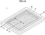
- Figs. 1A through 1C are drawings illustrating an example of a light emitter cover according to the first embodiment.
- Fig. 1A is an axonometric view.
- Fig. 1B is a partial cross-sectional view taken along a line A-A in Fig. 1A .
- Fig. 1C is a partial cross-sectional view taken along a line B-B in Fig. 1A .
- a light emitter cover 1 includes a glass plate 10, a frame 20, and low melting glass 40.
- the glass plate 10 is sealed to the frame 20 via the low melting glass 40 such as to close an opening 20x (see Fig. 3 ) of the frame 20.
- Fig. 2 is an axonometric view illustrating an example of the glass plate of the light emitter cover according to the first embodiment.
- the glass plate 10 is a rectangular shape, having an upper face 10t, a lower face 10b, and a peripheral side surface 10s.
- the glass plate 10 is formed in conformity to the specification of the frame 20.
- the size is not limited to particular dimensions, the glass plate 10 may be approximately 20-mm long, 30-mm wide, and 1-mm thick, for example.
- Borosilicate glass may be used as the glass plate 10.
- the glass plate 10 serves as a window which allows the passage of light emitted from the light emitting devices.
- transmissivity for the wavelengths of the light emitting devices is designed to be greater or equal to a predetermined value (e.g., 99%).
- the upper face 10t and the lower face 10b of the glass plate 10 may have an antireflection film formed thereon.
- Figs. 3A and 3B are axonometric views illustrating an example of the frame of the light emitter cover according to the first embodiment.
- Fig. 3A illustrates the whole view
- Fig. 3B illustrates a partial enlarged view of a portion C illustrated in Fig. 3A .
- the frame 20 is a metal member having the opening 20x smaller than the glass plate 10, and may be a picture frame shape, for example.
- the metal that forms the frame 20 may be an alloy of nickel and iron, for example.
- the surface of the frame 20 may have a surface treatment, such as plating, applied thereto.
- the frame 20 has an encircling (i.e., ring-shaped) step 30 formed on the side toward the opening 20x.
- the step 30 includes a placement face 31 and wall faces 32.
- the placement face 31 extends substantially parallel to an upper face 20t of the frame 20 at a recessed position relative to (i.e., at a lower vertical position than) the upper face 20t of the frame 20.
- the placement face 31 comes in contact with the lower face 10b of the glass plate 10 so as to provide support for the glass plate 10.
- the placement face 31 suffices as long as some portions thereof extend substantially parallel to the upper face of the frame 20, and may have a portion that is not parallel to the upper face of the frame 20.
- the expression "extending substantially parallel to the upper face of the frame 20" refers to the fact that the face is substantially parallel to the upper face of the frame 20 to the extent that the placement of the glass plate 10 is not impaired.
- the wall faces 32 are portions connecting the placement face 31 to the upper face 20t of the frame 20.
- the wall faces 32 include first wall faces 32a situated near the opposite ends of each of the four inner sides of the encircling step 30, and include a second wall face 32b situated between the first wall faces 32a.
- the term "the four inner sides of the encircling step 30" refers to the four sides forming the perimeter of the opening 20x when viewed in the direction perpendicular to the upper face 20t of the frame 20.
- the first wall faces 32a extend perpendicularly to the placement face 31 for the purpose of aligning the glass plate 10.
- This "perpendicular" condition does not require an exact right angle, and only requires that the faces are perpendicular to the placement face 31 to the extent that the alignment of the glass plate 10 is not impaired. This definition of the condition will hereinafter be applicable in similar situations.
- a minute gap i.e., clearance
- the gap between the first wall faces 32a and the peripheral side surface 10s of the glass plate 10 may be approximately 100 micrometers, for example.
- the second wall face 32b has an inclination angle ⁇ (see Fig. 1C ) that is less steep than the first wall faces 32a.
- the second wall face 32b is tilted with respect to the placement face 31 such that the distance between the second wall face 32b and the peripheral side surface 10s of the glass plate 10 increases toward the upper face 20t of the frame 20.
- the inclination angle ⁇ is set greater than or equal to the minimum angle at which the melted mass of the low melting glass 40 starts sliding on its own weight.
- the inclination angle ⁇ may be approximately 30 to 60 degrees, for example.
- the second wall face 32b preferably extend the same distance toward the opposite ends from the center (i.e., a midpoint between the opposite ends) of each inner side of the step 30, for example.
- the ratio of the length of the first wall faces 32a to the length of the second wall face 32b along the inner side is preferably about 1:1 to 1:9. These conditions serve to reliably seal the glass plate 10 to the frame 20.
- the low melting glass 40 which is a member for sealing the glass plate 10 to the frame 20, is made of a material having a lower melting point than the glass plate 10.
- Low melting glass containing bismuth as a main component without containing lead or low melting glass containing vanadium without containing lead may be used as the low melting glass 40, for example.
- the gap between the first wall faces 32a and the peripheral side surface 10s of the glass plate 10 and the gap between the second wall face 32b and the peripheral side surface 10s of the glass plate 10 are filled with the low melting glass 40.
- the upper face 10t of the glass plate 10 is situated above the upper face 20t of the frame 20.
- the low melting glass 40 covers the portion of the peripheral side surface 10s of the glass plate 10 that is situated above the upper face 20t of the frame 20. Namely, the entire peripheral side surface 10s of the glass plate 10 is in contact with the low melting glass 40 (i.e., wetted by the low melting glass 40).
- the low melting glass 40 may flow into between the placement face 31 and the perimeter of the lower face 10b of the glass plate 10.
- Figs. 4A and 4B to Figs. 7A through 7C are drawings illustrating the method of sealing the glass plate to the frame with the low melting glass.
- the frame 20 having the opening 20x and the step 30 is prepared.
- the frame 20 may be made by a stamping process using a metal material such as an alloy of nickel and iron, for example.
- the surface of the frame 20 may have a surface treatment such as plating applied thereto after the stamping process.
- the glass plate 10 having a rectangular shape is cut from a large size glass plate made of borosilicate glass or the like, for example.
- the glass plate 10 is placed in the opening 20x of the frame 20 such that the perimeter of the lower face 10b (see Fig. 2 , for example) of the glass plate 10 comes in contact with the placement face 31.
- the upper face 10t and the lower face 10b of the glass plate 10 may have an antireflection film formed thereon.
- low melting glass particles 40a are formed into a picture frame shape, followed by being sintered at a predetermined temperature to create a low melting glass 40b illustrated in a lower part of Fig. 5 .
- the sintered low melting glass 40b contracts relative to the shape of the low melting glass particles 40a, with the center area of each inner side and each outer side bulging outwardly.
- the low melting glass particles 40a, the sintered low melting glass 40b, and the sealed low melting glass 40 are denoted with respective reference numerals.
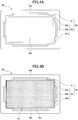
- Fig. 6A is a plan view.
- Fig. 6B is a partial cross-sectional view taken along a line A-A in Fig. 6A .
- Fig. 6C is a partial cross-sectional view taken along a line B-B in Fig. 6A .
- Each inner side and each outer side of the low melting glass 40b has an outwardly bulging center area, so that a gap between the low melting glass 40b and the peripheral side surface 10s of the glass plate 10 increases around the center area of each inner side and each outer side.
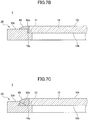
- Fig. 7A is a plan view.
- Fig. 7B is a partial cross-sectional view taken along a line A-A in Fig. 7A .
- Fig. 7C is a partial cross-sectional view taken along a line B-B in Fig. 7A .
- Figs. 8A and 8B through Figs. 10A through 10C are drawings illustrating a method of sealing a frame according to a comparative example.
- a frame 200 having an opening 200x is prepared.
- the frame 200 has an encircling (i.e., ring-shaped) step 300 formed on the side toward the opening 200x.
- the step 300 includes a placement face 310 and wall faces 320.
- the placement face 310 extends substantially parallel to an upper face 200t of the frame 200 at a recessed position relative to (i.e., at a lower vertical position than) the upper face 200t of the frame 200.
- the placement face 31 comes in contact with the lower face 10b of the glass plate 10 so as to provide support for the glass plate 10.
- the wall faces 320 are portions connecting the placement face 310 to the upper face 200t of the frame 200.
- the entirety of the wall faces 320 extends perpendicularly to the placement face 310. There is no inclined face corresponding to the second wall face 32b of the frame 20.
- the same rectangular-shaped glass plate 10 as the one shown in Fig. 4B is prepared, and is placed in the opening 200x of the frame 200 such that the perimeter of the lower face 10b of the glass plate 10 (see Fig. 2 ) comes in contact with the placement face 310.
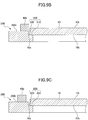
- Fig. 9A is a plan view.
- Fig. 9B is a partial cross-sectional view taken along a line A-A in Fig. 9A .
- Fig. 9C is a partial cross-sectional view taken along a line B-B in Fig. 9A .
- Each inner side and each outer side of the low melting glass 40b has an outwardly bulging center area, so that a gap between the low melting glass 40b and the peripheral side surface 10s of the glass plate 10 increases around the center area of each inner side and each outer side. Because of this, the center area of each inner side of the low melting glass 40b does not reach the position of the step 300.
- Fig. 10A is a plan view.
- Fig. 10B is a partial cross-sectional view taken along a line A-A in Fig. 10A .
- Fig. 10C is a partial cross-sectional view taken along a line B-B in Fig. 10A .
- the center area of each inner side and each outer side of the low melting glass 40b bulges outwardly, so that the center area of each inner side of the low melting glass 40b does not reach the position of the step 300. Because of this, the melted mass of the low melting glass 40b does not readily flow toward the peripheral side surface 10s at the center area of each inner side and each outer side of the low melting glass 40b.
- a likely resulting condition is that the peripheral side surface 10s of the glass plate 10 is not wetted (as illustrated in Fig. 10C ), or only partly wetted, by the low melting glass 40 at the center area of each inner side and each outer side of the low melting glass 40b. It is thus difficult to reliably seal the entire peripheral side surface 10s of the glass plate 10.
- the frame 20 of the light emitter cover 1 has the second wall face 32b, at the position corresponding to the bulges of the low melting glass 40b, extending at an inclination angle greater than or equal to the minimum angle at which the melted mass of the low melting glass 40b starts sliding on its own weight.
- the melted liquid mass of the low melting glass 40b flows on the second wall face 32b toward the peripheral side surface 10s of the glass plate 10, resulting in being cured while being in contact with the peripheral side surface 10s.
- the entire peripheral side surface 10s of the glass plate 10 is reliably sealed with the low melting glass 40, which improves sealing reliability between the glass plate 10 and the frame 20.
- Lead-free low melting glass has poor wettability unlike low melting glass containing lead. Because of this, the use of the tilted second wall face 32b is advantageous especially when lead-free low melting glass is used as a seal between the glass plate 10 and the frame 20.
- a method of applying a large quantity of low melting glass to seal a glass plate to a frame is not used for the light emitter cover 1, which facilitates the size reduction of the light emitter cover 1.
- the first wall faces 32a extend perpendicularly to the placement face 31. At the positions of the first wall faces 32a, however, the low melting glass 40b have no bulges or only minute bulges, so that a gap between the low melting glass 40b and the peripheral side surface 10s of the glass plate 10 is small. At these positions, therefore, the entire peripheral side surface 10s of the glass plate 10 is reliably sealed even in the absence of inclined faces such as the second wall face 32b. Notwithstanding this, the first wall faces 32a may be provided as inclined faces at the inclination angle ⁇ similarly to the second wall face 32b. Namely, the entire wall faces 32 may be provided as inclined faces at the inclination angle ⁇ . With such an arrangement, aligning the glass plate 10 with respect to the frame 20 becomes more difficult. A dedicated tool for alignment, for example, may be made to cope with this issue.
- first wall faces 32a extending perpendicularly to the placement face 31 is advantageous from the viewpoint of alignment of the glass plate 10 relative to the frame 20, and is also advantageous when considering the tilt of the glass plate 10 relative to the placement face 31. Namely, the perimeter of the lower face 10b of the glass plate 10 is prevented from climbing over the inclined second wall face 32b.
- the first variation of the first embodiment is directed to an example of a light emitter cover with a step having a different shape than the first embodiment.
- a description of the same or similar constituent elements as those of the previously provided descriptions may be omitted as appropriate.
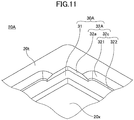
- Fig. 11 is an axonometric partial view of the frame of a light emitter cover according to the first variation of the first embodiment.
- Fig. 11 illustrates the portion corresponding to Fig. 3B .
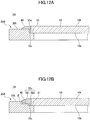
- Figs. 12A and 12B are partial cross-sectional views of the light emitter cover according to the first variation of the first embodiment.
- Figs. 12A and 12B illustrate cross-sections corresponding to Fig. 1B and Fig. 1C , respectively.
- a light emitter cover 1A according to the first variation of the first embodiment differs from the light emitter cover 1 (see Figs. 1A through 1C to Figs. 3A and 3B ) in that a frame 20A replaces the frame 20.
- the frame 20A is a metal member having the opening 20x smaller than the glass plate 10, and may be a picture frame shape, for example.
- the metal that forms the frame 20A may be an alloy of nickel and iron, for example.
- the surface of the frame 20A may have a surface treatment, such as plating, applied thereto.
- the frame 20A has an encircling (i.e., ring-shaped) step 30A formed on the side toward the opening 20x.
- the step 30A includes a placement face 31 and wall faces 32A.
- the placement face 31 is the same as that of the frame 20.
- the wall faces 32A are portions connecting the placement face 31 to the upper face 20t of the frame 20A.
- the wall faces 32A include first wall faces 32a situated near the opposite ends of each of the four inner sides of the encircling step 30A, and include a second wall face 32c situated between the first wall faces 32a.
- the second wall face 32c includes a first face 321 situated toward the upper face 20t of the frame 20A and a second face 322 situated between the first face 321 and the placement face 31.
- the first face 321 extends at an inclination angle smaller than the first wall faces 32a with respect to the placement face 31.
- the first face 321 is tilted with respect to the placement face 31 such that the distance between the first face 321 and the peripheral side surface 10s of the glass plate 10 increases toward the upper face 20t of the frame 20A.
- the inclination angle ⁇ is set greater than or equal to the minimum angle at which the melted mass of the low melting glass 40 starts sliding on its own weight.
- the inclination angle ⁇ may be approximately 30 to 60 degrees, for example.
- the second face 322 has an inclination angle steeper than the first face 321 with respect to the placement face 31.
- the second face 322 may extend perpendicularly to the placement face 31, for example.
- a minute gap i.e., clearance
- the gap between the second face 322 and the peripheral side surface 10s of the glass plate 10 may be approximately 100 micrometers, for example.
- the frame 20A of the light emitter cover 1A has the first face 321 of the second wall face 32c, at the position corresponding to the bulges of the low melting glass 40b (see Fig. 5 , for example), extending at an inclination angle greater than or equal to the minimum angle at which the melted mass of the low melting glass 40b starts sliding on its own weight.
- Figs. 12A and 12B therefore, the melted liquid mass of the low melting glass 40b flows on the first face 321 toward the peripheral side surface 10s of the glass plate 10, resulting in being cured while being in contact with the peripheral side surface 10s. With this arrangement, the entire peripheral side surface 10s of the glass plate 10 is reliably sealed.
- the second face 322 as a vertical wall, for example, on the side of the first face 321 toward the placement face 31 allows the glass plate 10 to be more readily aligned in the opening 20x of the frame 20A.
- the plane shape of the glass plate does not have to be rectangular, and may alternatively be a hexagonal shape, for example.
- a cover for a light emitter that has an improved sealing reliability between a glass plate and a frame while facilitating size reduction.
Landscapes
- Chemical & Material Sciences (AREA)
- Engineering & Computer Science (AREA)
- Ceramic Engineering (AREA)
- Life Sciences & Earth Sciences (AREA)
- Chemical Kinetics & Catalysis (AREA)
- General Chemical & Material Sciences (AREA)
- Geochemistry & Mineralogy (AREA)
- Materials Engineering (AREA)
- Organic Chemistry (AREA)
- Led Device Packages (AREA)
- Joining Of Glass To Other Materials (AREA)
- Semiconductor Lasers (AREA)
Abstract
Description
- The disclosures herein relate to a cover for a light emitter.
- A light emitter having one or more light emitting devices such as laser diodes is known in the art. When the airtightness of a light emitter matters, a light emitter cover having a glass plate sealed to a frame via low melting glass is mounted to a case in which one or more light emitting devices are placed, for example.
- With the advancement of technology, heat quantity generated by a light emitting device increases, which makes it necessary to bond the glass plate and the frame together more firmly than ever for a light emitter cover. For the purpose of firm bonding, there is a need to fill a gap, with low melting glass, between the peripheral side surface of a glass plate and the inner wall face of a frame so that the low melting glass wets the entire peripheral side surface of the glass plate.
- For example, there is a method of filling a gap with low melting glass by applying low melting glass in paste form to the gap between the peripheral side surface of a glass plate and the inner sidewall of a frame, followed by curing the paste.
- The method of applying low melting glass described above needs a large quantity of low melting glass in order to wet the entire peripheral side surface of a glass plate. As a result, the size of a light emitter cover increases, giving rise to the problem of an increase in the size of the light emitter. Reducing the quantity of low melting glass to facilitate size reduction results in a failure to wet the entire peripheral side surface of a glass plate with low melting glass. This causes the problem of a lowered sealing reliability between the glass plate and the frame.
- Accordingly, it may be desired to provide a cover for a light emitter that has an improved sealing reliability between a glass plate and a frame while facilitating size reduction.
- [Patent Document 1] Japanese Patent Application Publication No.
2006-156528 - According to an aspect of the embodiment, a cover for a light emitter having one or more light emitting devices includes a glass plate having an upper face, a lower face, and a peripheral side surface, a frame made of metal having an opening smaller than the glass plate, and a low melting glass having a lower melting point than the glass plate, the glass plate being sealed to the frame with the low melting glass to close the opening, wherein the frame has an encircling step formed on a side thereof to which the glass plate is sealed, wherein the encircling step includes a placement face situated at a recessed position relative to an upper surface of the frame, the placement face being in contact with a perimeter of the lower face of the glass plate to have the glass plate placed thereon, and a wall face connecting the upper surface of the frame and the placement face, wherein the wall face includes first wall faces situated at opposite ends of each inner side of the encircling step and a second wall face situated between the first wall faces, and the second wall face includes a face extending at a smaller inclination angle than the first wall faces with respect to the placement face, and wherein gaps between the first wall faces and the peripheral side surface of the glass plate and a gap between the second wall face and the peripheral side surface of the glass plate are filled with the low melting glass.
-
-
Figs. 1A through 1C are drawings illustrating an example of a light emitter cover according to a first embodiment; -
Fig. 2 is an axonometric view illustrating an example of the glass plate of the light emitter cover according to the first embodiment; -
Figs. 3A and 3B are axonometric views illustrating an example of the frame of the light emitter cover according to the first embodiment; -
Figs. 4A and 4B are drawings illustrating a method of sealing the glass plate to the frame with low melting glass; -
Fig. 5 is a drawing illustrating the method of sealing the glass plate to the frame with low melting glass; -
Figs. 6A through 6C are drawings illustrating the method of sealing the glass plate to the frame with low melting glass; -
Figs. 7A through 7C are drawings illustrating the method of sealing the glass plate to the frame with low melting glass; -
Figs. 8A and 8B are drawings illustrating a method of sealing a frame according to a comparative example; -
Figs. 9A through 9C are drawings illustrating the method of sealing a frame according to the comparative example; -
Figs. 10A through 10C are drawings illustrating the method of sealing a frame according to the comparative example; -
Fig. 11 is an axonometric partial view illustrating an example of a frame of a light emitter cover according to a first variation of the first embodiment; and -
Figs. 12A and 12B are cross-sectional partial views illustrating the example of the frame of a light emitter cover according to the first variation of the first embodiment. - In the following, embodiments will be described by referring to the accompanying drawings. In these drawings, the same elements are referred to by the same references, and a duplicate description thereof may be omitted.
-
Figs. 1A through 1C are drawings illustrating an example of a light emitter cover according to the first embodiment.Fig. 1A is an axonometric view.Fig. 1B is a partial cross-sectional view taken along a line A-A inFig. 1A .Fig. 1C is a partial cross-sectional view taken along a line B-B inFig. 1A . - Referring to
Figs. 1A through 1C , alight emitter cover 1 includes aglass plate 10, aframe 20, andlow melting glass 40. Theglass plate 10 is sealed to theframe 20 via thelow melting glass 40 such as to close an opening 20x (seeFig. 3 ) of theframe 20. Thelight emitter cover 1, which is used as a cover for a light emitter having one or more light emitting devices such as laser diodes or photo diodes, serves as a member for hermetically sealing the light emitting devices inside the light emitter. -
Fig. 2 is an axonometric view illustrating an example of the glass plate of the light emitter cover according to the first embodiment. As illustrated inFig. 2 , theglass plate 10 is a rectangular shape, having anupper face 10t, alower face 10b, and aperipheral side surface 10s. Theglass plate 10 is formed in conformity to the specification of theframe 20. Although the size is not limited to particular dimensions, theglass plate 10 may be approximately 20-mm long, 30-mm wide, and 1-mm thick, for example. - Borosilicate glass may be used as the
glass plate 10. When thelight emitter cover 1 is used as the cover for a package in which light emitting devices are placed, theglass plate 10 serves as a window which allows the passage of light emitted from the light emitting devices. For this purpose, transmissivity for the wavelengths of the light emitting devices is designed to be greater or equal to a predetermined value (e.g., 99%). Theupper face 10t and thelower face 10b of theglass plate 10 may have an antireflection film formed thereon. -
Figs. 3A and 3B are axonometric views illustrating an example of the frame of the light emitter cover according to the first embodiment.Fig. 3A illustrates the whole view, andFig. 3B illustrates a partial enlarged view of a portion C illustrated inFig. 3A . As is illustrated inFigs. 3A and 3B , theframe 20 is a metal member having the opening 20x smaller than theglass plate 10, and may be a picture frame shape, for example. The metal that forms theframe 20 may be an alloy of nickel and iron, for example. The surface of theframe 20 may have a surface treatment, such as plating, applied thereto. - The
frame 20 has an encircling (i.e., ring-shaped)step 30 formed on the side toward theopening 20x. Thestep 30 includes aplacement face 31 and wall faces 32. Theplacement face 31 extends substantially parallel to anupper face 20t of theframe 20 at a recessed position relative to (i.e., at a lower vertical position than) theupper face 20t of theframe 20. Theplacement face 31 comes in contact with thelower face 10b of theglass plate 10 so as to provide support for theglass plate 10. Theplacement face 31 suffices as long as some portions thereof extend substantially parallel to the upper face of theframe 20, and may have a portion that is not parallel to the upper face of theframe 20. The expression "extending substantially parallel to the upper face of theframe 20" refers to the fact that the face is substantially parallel to the upper face of theframe 20 to the extent that the placement of theglass plate 10 is not impaired. - The wall faces 32 are portions connecting the
placement face 31 to theupper face 20t of theframe 20. The wall faces 32 include first wall faces 32a situated near the opposite ends of each of the four inner sides of the encirclingstep 30, and include asecond wall face 32b situated between the first wall faces 32a. The term "the four inner sides of the encirclingstep 30" refers to the four sides forming the perimeter of theopening 20x when viewed in the direction perpendicular to theupper face 20t of theframe 20. - The first wall faces 32a extend perpendicularly to the
placement face 31 for the purpose of aligning theglass plate 10. This "perpendicular" condition does not require an exact right angle, and only requires that the faces are perpendicular to theplacement face 31 to the extent that the alignment of theglass plate 10 is not impaired. This definition of the condition will hereinafter be applicable in similar situations. A minute gap (i.e., clearance) is formed between the first wall faces 32a and theperipheral side surface 10s of theglass plate 10. The gap between the first wall faces 32a and theperipheral side surface 10s of theglass plate 10 may be approximately 100 micrometers, for example. - The
second wall face 32b has an inclination angle θ (seeFig. 1C ) that is less steep than the first wall faces 32a. Thesecond wall face 32b is tilted with respect to theplacement face 31 such that the distance between thesecond wall face 32b and theperipheral side surface 10s of theglass plate 10 increases toward theupper face 20t of theframe 20. The inclination angle θ is set greater than or equal to the minimum angle at which the melted mass of thelow melting glass 40 starts sliding on its own weight. The inclination angle θ may be approximately 30 to 60 degrees, for example. - The
second wall face 32b preferably extend the same distance toward the opposite ends from the center (i.e., a midpoint between the opposite ends) of each inner side of thestep 30, for example. On each inner side of thestep 30, the ratio of the length of the first wall faces 32a to the length of thesecond wall face 32b along the inner side is preferably about 1:1 to 1:9. These conditions serve to reliably seal theglass plate 10 to theframe 20. - By referring to
Figs. 1A through 1C again, thelow melting glass 40, which is a member for sealing theglass plate 10 to theframe 20, is made of a material having a lower melting point than theglass plate 10. Low melting glass containing bismuth as a main component without containing lead or low melting glass containing vanadium without containing lead may be used as thelow melting glass 40, for example. - The gap between the first wall faces 32a and the
peripheral side surface 10s of theglass plate 10 and the gap between thesecond wall face 32b and theperipheral side surface 10s of theglass plate 10 are filled with thelow melting glass 40. Theupper face 10t of theglass plate 10 is situated above theupper face 20t of theframe 20. Thelow melting glass 40 covers the portion of theperipheral side surface 10s of theglass plate 10 that is situated above theupper face 20t of theframe 20. Namely, the entireperipheral side surface 10s of theglass plate 10 is in contact with the low melting glass 40 (i.e., wetted by the low melting glass 40). Thelow melting glass 40 may flow into between theplacement face 31 and the perimeter of thelower face 10b of theglass plate 10. - In the following, a description will be given of the method of sealing the
glass plate 10 to theframe 20 with thelow melting glass 40.Figs. 4A and 4B toFigs. 7A through 7C are drawings illustrating the method of sealing the glass plate to the frame with the low melting glass. As illustrated inFig. 4A , theframe 20 having theopening 20x and thestep 30 is prepared. Theframe 20 may be made by a stamping process using a metal material such as an alloy of nickel and iron, for example. The surface of theframe 20 may have a surface treatment such as plating applied thereto after the stamping process. - As illustrated in
Fig. 4B , theglass plate 10 having a rectangular shape is cut from a large size glass plate made of borosilicate glass or the like, for example. Theglass plate 10 is placed in theopening 20x of theframe 20 such that the perimeter of thelower face 10b (seeFig. 2 , for example) of theglass plate 10 comes in contact with theplacement face 31. Theupper face 10t and thelower face 10b of theglass plate 10 may have an antireflection film formed thereon. - Subsequently, as illustrated in an upper part of
Fig. 5 , for example, lowmelting glass particles 40a are formed into a picture frame shape, followed by being sintered at a predetermined temperature to create alow melting glass 40b illustrated in a lower part ofFig. 5 . The sinteredlow melting glass 40b contracts relative to the shape of the lowmelting glass particles 40a, with the center area of each inner side and each outer side bulging outwardly. For the sake of convenience of explanation, the lowmelting glass particles 40a, the sinteredlow melting glass 40b, and the sealedlow melting glass 40 are denoted with respective reference numerals. - As illustrated in
Figs. 6A through 6C , thelow melting glass 40b is placed on theframe 20 having theglass plate 10 seated thereon (seeFig. 4B ).Fig. 6A is a plan view.Fig. 6B is a partial cross-sectional view taken along a line A-A inFig. 6A .Fig. 6C is a partial cross-sectional view taken along a line B-B inFig. 6A . Each inner side and each outer side of thelow melting glass 40b has an outwardly bulging center area, so that a gap between thelow melting glass 40b and theperipheral side surface 10s of theglass plate 10 increases around the center area of each inner side and each outer side. - As illustrated in
Figs. 7A through 7C , thelow melting glass 40b is melted at or above a predetermined temperature and then cured, so that theglass plate 10 is sealed to theframe 20. The cured glass is referred to as thelow melting glass 40. With this, thelight emitter cover 1 is completed in final form.Fig. 7A is a plan view.Fig. 7B is a partial cross-sectional view taken along a line A-A inFig. 7A .Fig. 7C is a partial cross-sectional view taken along a line B-B inFig. 7A . - In the following, the characteristic advantages of the
light emitter cover 1 will be described by referring to a comparative example.Figs. 8A and 8B throughFigs. 10A through 10C are drawings illustrating a method of sealing a frame according to a comparative example. - As illustrated in
Fig. 8A , aframe 200 having anopening 200x is prepared. Theframe 200 has an encircling (i.e., ring-shaped)step 300 formed on the side toward theopening 200x. Thestep 300 includes aplacement face 310 and wall faces 320. Theplacement face 310 extends substantially parallel to anupper face 200t of theframe 200 at a recessed position relative to (i.e., at a lower vertical position than) theupper face 200t of theframe 200. Theplacement face 31 comes in contact with thelower face 10b of theglass plate 10 so as to provide support for theglass plate 10. The wall faces 320 are portions connecting theplacement face 310 to theupper face 200t of theframe 200. The entirety of the wall faces 320 extends perpendicularly to theplacement face 310. There is no inclined face corresponding to thesecond wall face 32b of theframe 20. - As illustrated in
Fig. 8B , the same rectangular-shapedglass plate 10 as the one shown inFig. 4B is prepared, and is placed in theopening 200x of theframe 200 such that the perimeter of thelower face 10b of the glass plate 10 (seeFig. 2 ) comes in contact with theplacement face 310. - As illustrated in
Fig. 9A , the samelow melting glass 40b as the one shown inFig. 5 is prepared, and is placed on theframe 200 having theglass plate 10 seated thereon (seeFig. 8B ).Fig. 9A is a plan view.Fig. 9B is a partial cross-sectional view taken along a line A-A inFig. 9A .Fig. 9C is a partial cross-sectional view taken along a line B-B inFig. 9A . Each inner side and each outer side of thelow melting glass 40b has an outwardly bulging center area, so that a gap between thelow melting glass 40b and theperipheral side surface 10s of theglass plate 10 increases around the center area of each inner side and each outer side. Because of this, the center area of each inner side of thelow melting glass 40b does not reach the position of thestep 300. - As illustrated in
Figs. 10A through 10C , thelow melting glass 40b is melted at or above a predetermined temperature and then cured, so that theglass plate 10 is sealed to theframe 200. The cured glass is referred to as thelow melting glass 40.Fig. 10A is a plan view.Fig. 10B is a partial cross-sectional view taken along a line A-A inFig. 10A .Fig. 10C is a partial cross-sectional view taken along a line B-B inFig. 10A . - As is illustrated in
Figs. 9A through 9C , the center area of each inner side and each outer side of thelow melting glass 40b bulges outwardly, so that the center area of each inner side of thelow melting glass 40b does not reach the position of thestep 300. Because of this, the melted mass of thelow melting glass 40b does not readily flow toward theperipheral side surface 10s at the center area of each inner side and each outer side of thelow melting glass 40b. A likely resulting condition is that theperipheral side surface 10s of theglass plate 10 is not wetted (as illustrated inFig. 10C ), or only partly wetted, by thelow melting glass 40 at the center area of each inner side and each outer side of thelow melting glass 40b. It is thus difficult to reliably seal the entireperipheral side surface 10s of theglass plate 10. - In contrast, the
frame 20 of thelight emitter cover 1 has thesecond wall face 32b, at the position corresponding to the bulges of thelow melting glass 40b, extending at an inclination angle greater than or equal to the minimum angle at which the melted mass of thelow melting glass 40b starts sliding on its own weight. As illustrated inFig. 7C , therefore, the melted liquid mass of thelow melting glass 40b flows on thesecond wall face 32b toward theperipheral side surface 10s of theglass plate 10, resulting in being cured while being in contact with theperipheral side surface 10s. With this arrangement, the entireperipheral side surface 10s of theglass plate 10 is reliably sealed with thelow melting glass 40, which improves sealing reliability between theglass plate 10 and theframe 20. - If there is a gap between the
low melting glass 40 and part of theperipheral side surface 10s of theglass plate 10 as a result of a failure to seal the entireperipheral side surface 10s of theglass plate 10 with thelow melting glass 40, there is a risk that a crack starts from the gap and develops in thelow melting glass 40 upon thermal impact. Securely sealing the entireperipheral side surface 10s of theglass plate 10 with thelow melting glass 40 can prevent a crack from developing in thelow melting glass 40 upon thermal impact. It may be noted that thermal impact may occur when thelight emitter cover 1 is placed in the environment in which the temperature frequently alternates between a high temperature and a low temperature, for example. - Lead-free low melting glass has poor wettability unlike low melting glass containing lead. Because of this, the use of the tilted
second wall face 32b is advantageous especially when lead-free low melting glass is used as a seal between theglass plate 10 and theframe 20. - A method of applying a large quantity of low melting glass to seal a glass plate to a frame is not used for the
light emitter cover 1, which facilitates the size reduction of thelight emitter cover 1. - The first wall faces 32a extend perpendicularly to the
placement face 31. At the positions of the first wall faces 32a, however, thelow melting glass 40b have no bulges or only minute bulges, so that a gap between thelow melting glass 40b and theperipheral side surface 10s of theglass plate 10 is small. At these positions, therefore, the entireperipheral side surface 10s of theglass plate 10 is reliably sealed even in the absence of inclined faces such as thesecond wall face 32b. Notwithstanding this, the first wall faces 32a may be provided as inclined faces at the inclination angle θ similarly to thesecond wall face 32b. Namely, the entire wall faces 32 may be provided as inclined faces at the inclination angle θ. With such an arrangement, aligning theglass plate 10 with respect to theframe 20 becomes more difficult. A dedicated tool for alignment, for example, may be made to cope with this issue. - Use of the first wall faces 32a extending perpendicularly to the
placement face 31 is advantageous from the viewpoint of alignment of theglass plate 10 relative to theframe 20, and is also advantageous when considering the tilt of theglass plate 10 relative to theplacement face 31. Namely, the perimeter of thelower face 10b of theglass plate 10 is prevented from climbing over the inclinedsecond wall face 32b. - The first variation of the first embodiment is directed to an example of a light emitter cover with a step having a different shape than the first embodiment. In connection with the first variation of the first embodiment, a description of the same or similar constituent elements as those of the previously provided descriptions may be omitted as appropriate.
-
Fig. 11 is an axonometric partial view of the frame of a light emitter cover according to the first variation of the first embodiment.Fig. 11 illustrates the portion corresponding toFig. 3B .Figs. 12A and 12B are partial cross-sectional views of the light emitter cover according to the first variation of the first embodiment.Figs. 12A and 12B illustrate cross-sections corresponding toFig. 1B and Fig. 1C , respectively. - As illustrated in
Fig. 11 andFigs. 12A and 12B , alight emitter cover 1A according to the first variation of the first embodiment differs from the light emitter cover 1 (seeFigs. 1A through 1C toFigs. 3A and 3B ) in that aframe 20A replaces theframe 20. - Similarly to the
frame 20, theframe 20A is a metal member having the opening 20x smaller than theglass plate 10, and may be a picture frame shape, for example. The metal that forms theframe 20A may be an alloy of nickel and iron, for example. The surface of theframe 20A may have a surface treatment, such as plating, applied thereto. - The
frame 20A has an encircling (i.e., ring-shaped)step 30A formed on the side toward theopening 20x. Thestep 30A includes aplacement face 31 and wall faces 32A. Theplacement face 31 is the same as that of theframe 20. The wall faces 32A are portions connecting theplacement face 31 to theupper face 20t of theframe 20A. The wall faces 32A include first wall faces 32a situated near the opposite ends of each of the four inner sides of theencircling step 30A, and include asecond wall face 32c situated between the first wall faces 32a. Thesecond wall face 32c includes afirst face 321 situated toward theupper face 20t of theframe 20A and asecond face 322 situated between thefirst face 321 and theplacement face 31. - The
first face 321 extends at an inclination angle smaller than the first wall faces 32a with respect to theplacement face 31. Thefirst face 321 is tilted with respect to theplacement face 31 such that the distance between thefirst face 321 and theperipheral side surface 10s of theglass plate 10 increases toward theupper face 20t of theframe 20A. The inclination angle θ is set greater than or equal to the minimum angle at which the melted mass of thelow melting glass 40 starts sliding on its own weight. The inclination angle θ may be approximately 30 to 60 degrees, for example. - The
second face 322 has an inclination angle steeper than thefirst face 321 with respect to theplacement face 31. Thesecond face 322 may extend perpendicularly to theplacement face 31, for example. A minute gap (i.e., clearance) is formed between thesecond face 322 and theperipheral side surface 10s of theglass plate 10. The gap between thesecond face 322 and theperipheral side surface 10s of theglass plate 10 may be approximately 100 micrometers, for example. - The
frame 20A of thelight emitter cover 1A has thefirst face 321 of thesecond wall face 32c, at the position corresponding to the bulges of thelow melting glass 40b (seeFig. 5 , for example), extending at an inclination angle greater than or equal to the minimum angle at which the melted mass of thelow melting glass 40b starts sliding on its own weight. As illustrated inFigs. 12A and 12B , therefore, the melted liquid mass of thelow melting glass 40b flows on thefirst face 321 toward theperipheral side surface 10s of theglass plate 10, resulting in being cured while being in contact with theperipheral side surface 10s. With this arrangement, the entireperipheral side surface 10s of theglass plate 10 is reliably sealed. - With respect to the
second wall face 32c, provision of thesecond face 322 as a vertical wall, for example, on the side of thefirst face 321 toward theplacement face 31 allows theglass plate 10 to be more readily aligned in theopening 20x of theframe 20A. - Further, although the preferred embodiments have been described, the present invention is not limited to these embodiments, and various variations and modifications may be made without departing from the scope of the present invention.
- For example, the plane shape of the glass plate does not have to be rectangular, and may alternatively be a hexagonal shape, for example.
- According to at least one embodiment, a cover for a light emitter is provided that has an improved sealing reliability between a glass plate and a frame while facilitating size reduction.
Claims (8)
- A cover for a light emitter having one or more light emitting devices, comprising:a glass plate having an upper face, a lower face, and a peripheral side surface;a frame made of metal having an opening smaller than the glass plate; anda low melting glass having a lower melting point than the glass plate, the glass plate being sealed to the frame with the low melting glass to close the opening,wherein the frame has an encircling step formed on a side thereof to which the glass plate is sealed,wherein the encircling step includes:a placement face situated at a recessed position relative to an upper surface of the frame, the placement face being in contact with a perimeter of the lower face of the glass plate to have the glass plate placed thereon; anda wall face connecting the upper surface of the frame and the placement face,wherein the wall face includes first wall faces situated at opposite ends of each inner side of the encircling step and a second wall face situated between the first wall faces, andthe second wall face includes a face extending at a smaller inclination angle than the first wall faces with respect to the placement face, andwherein gaps between the first wall faces and the peripheral side surface of the glass plate and a gap between the second wall face and the peripheral side surface of the glass plate are filled with the low melting glass.
- The cover as claimed in claim 1, wherein the placement face includes a flat surface extending substantially parallel to the upper surface of the frame.
- The cover as claimed in claim 1 or 2, wherein the second wall face extends an equal length toward the opposite ends from a center of each inner side of the encircling step.
- The cover as claimed in any one of claims 1 to 3, wherein the first wall faces extend perpendicularly to the placement face.
- The cover as claimed in any one of claims 1 to 4, wherein the second wall face includes a first face situated toward the upper surface of the frame and a second face situated between the first face and the placement face, and the first face is the face extending at the smaller inclination angle than the first wall faces with respect to the placement face, the second face extending at a steeper inclination angle than the first face with respect to the placement face.
- The cover as claimed in any one of claims 1 to 5, wherein the smaller inclination angle of the second wall face is greater than or equal to a minimum angle at which a melted mass of the low melting glass starts sliding on own weight.
- The cover as claimed in any one of claims 1 to 6, wherein the upper face of the glass plate is situated above the upper surface of the frame, and a portion of the peripheral side surface of the glass plate situated above the upper surface of the frame is covered with the low melting glass.
- The cover as claimed in any one of claims 1 to 7, wherein the low melting glass contains no lead.
Applications Claiming Priority (1)
| Application Number | Priority Date | Filing Date | Title |
|---|---|---|---|
| JP2017104714A JP6805081B2 (en) | 2017-05-26 | 2017-05-26 | Lid for light emitting device |
Publications (2)
| Publication Number | Publication Date |
|---|---|
| EP3407395A1 true EP3407395A1 (en) | 2018-11-28 |
| EP3407395B1 EP3407395B1 (en) | 2019-10-09 |
Family
ID=62530074
Family Applications (1)
| Application Number | Title | Priority Date | Filing Date |
|---|---|---|---|
| EP18173164.7A Active EP3407395B1 (en) | 2017-05-26 | 2018-05-18 | Cover for light emitter |
Country Status (4)
| Country | Link |
|---|---|
| US (1) | US10141487B1 (en) |
| EP (1) | EP3407395B1 (en) |
| JP (1) | JP6805081B2 (en) |
| CN (1) | CN108962829B (en) |
Families Citing this family (2)
| Publication number | Priority date | Publication date | Assignee | Title |
|---|---|---|---|---|
| JP7152666B2 (en) * | 2019-03-08 | 2022-10-13 | 日亜化学工業株式会社 | Light-emitting device and manufacturing method thereof |
| JP2023088146A (en) * | 2021-12-14 | 2023-06-26 | 富士電機株式会社 | semiconductor equipment |
Citations (3)
| Publication number | Priority date | Publication date | Assignee | Title |
|---|---|---|---|---|
| US20050224827A1 (en) * | 2002-06-03 | 2005-10-13 | Dietrich Mund | Method for hermetically housing optical components, and optical components produced according to said mehtod |
| JP2006156528A (en) | 2004-11-26 | 2006-06-15 | Kyocera Corp | Semiconductor device |
| EP3038173A1 (en) * | 2014-12-23 | 2016-06-29 | LG Innotek Co., Ltd. | Light emitting device and lighting system |
Family Cites Families (19)
| Publication number | Priority date | Publication date | Assignee | Title |
|---|---|---|---|---|
| JP4944301B2 (en) * | 2000-02-01 | 2012-05-30 | パナソニック株式会社 | Optoelectronic device and manufacturing method thereof |
| JP2002033519A (en) * | 2000-07-14 | 2002-01-31 | Sumitomo Electric Ind Ltd | Optical communication package, window member thereof, and method of manufacturing the same |
| JP4894987B2 (en) * | 2001-06-29 | 2012-03-14 | 三洋電機株式会社 | Manufacturing method of display panel |
| JP3669351B2 (en) * | 2001-10-04 | 2005-07-06 | セイコーエプソン株式会社 | Electro-optical device and electronic apparatus |
| US20050140913A1 (en) * | 2002-08-29 | 2005-06-30 | Masahiro Yokota | Flat display device |
| KR100529071B1 (en) * | 2002-11-26 | 2005-11-15 | 삼성에스디아이 주식회사 | Plasma display panel having sealing structure for reducing noise |
| JP2006019633A (en) * | 2004-07-05 | 2006-01-19 | Canon Inc | Mounting structure of photoelectric conversion element |
| JP4796518B2 (en) * | 2007-02-06 | 2011-10-19 | 株式会社住友金属エレクトロデバイス | Ceramic lid |
| JP2009131999A (en) * | 2007-11-29 | 2009-06-18 | Nissha Printing Co Ltd | Mold for glass insert molding |
| JP2009150604A (en) * | 2007-12-20 | 2009-07-09 | Nippon Electric Glass Co Ltd | Top plate for cooker |
| JP2010171379A (en) * | 2008-12-25 | 2010-08-05 | Seiko Instruments Inc | Light-emitting device |
| BR112012003202B1 (en) * | 2009-10-29 | 2020-02-18 | Nichia Corporation | LIGHT EMISSION EQUIPMENT AND MANUFACTURING METHOD OF THE LIGHT EMISSION EQUIPMENT |
| KR101230774B1 (en) * | 2010-09-03 | 2013-02-06 | 알프스 덴키 가부시키가이샤 | Glass composite, electronic device using glass composite, and input device, and method for manufacturing glass composite |
| WO2012073868A1 (en) * | 2010-11-30 | 2012-06-07 | 三洋電機株式会社 | Photoelectric conversion device and method for manufacturing same |
| DK2773596T3 (en) * | 2011-11-02 | 2020-09-14 | Ferro Corp | MICROWAVE SEALING OF INORGANIC SUBSTRATES USING LOW MELTING GLASS SYSTEMS |
| JP2013222522A (en) * | 2012-04-13 | 2013-10-28 | Panasonic Corp | Organic electroluminescent element and method for manufacturing the same |
| JP2014138131A (en) * | 2013-01-18 | 2014-07-28 | Takara Kasei Kogyo Kk | Housing cover made of glass sheet, method for integrally molding housing and glass sheet, and structure of integrally molded housing and glass sheet |
| JP6400980B2 (en) * | 2013-08-26 | 2018-10-03 | 京セラ株式会社 | Cover member for optical device and optical device |
| JP2017059617A (en) * | 2015-09-15 | 2017-03-23 | パナソニックIpマネジメント株式会社 | Light emitting device |
-
2017
- 2017-05-26 JP JP2017104714A patent/JP6805081B2/en active Active
-
2018
- 2018-05-16 US US15/980,907 patent/US10141487B1/en active Active
- 2018-05-18 EP EP18173164.7A patent/EP3407395B1/en active Active
- 2018-05-21 CN CN201810490718.1A patent/CN108962829B/en active Active
Patent Citations (3)
| Publication number | Priority date | Publication date | Assignee | Title |
|---|---|---|---|---|
| US20050224827A1 (en) * | 2002-06-03 | 2005-10-13 | Dietrich Mund | Method for hermetically housing optical components, and optical components produced according to said mehtod |
| JP2006156528A (en) | 2004-11-26 | 2006-06-15 | Kyocera Corp | Semiconductor device |
| EP3038173A1 (en) * | 2014-12-23 | 2016-06-29 | LG Innotek Co., Ltd. | Light emitting device and lighting system |
Also Published As
| Publication number | Publication date |
|---|---|
| JP2018200946A (en) | 2018-12-20 |
| CN108962829A (en) | 2018-12-07 |
| US20180342656A1 (en) | 2018-11-29 |
| CN108962829B (en) | 2023-08-29 |
| EP3407395B1 (en) | 2019-10-09 |
| JP6805081B2 (en) | 2020-12-23 |
| US10141487B1 (en) | 2018-11-27 |
Similar Documents
| Publication | Publication Date | Title |
|---|---|---|
| CN110521011B (en) | Optical semiconductor device and method for manufacturing optical semiconductor device | |
| CN102473813B (en) | Light emitting device and method for manufacturing same | |
| TW200403455A (en) | Methods of sealing electronic, optical and electro-optical packages and related package and substrate designs | |
| EP3407395B1 (en) | Cover for light emitter | |
| US7667324B2 (en) | Systems, devices, components and methods for hermetically sealing electronic modules and packages | |
| US10411167B2 (en) | Semiconductor light emitting apparatus, stem part | |
| US20060102923A1 (en) | Optical element housing package | |
| JP2003224223A (en) | Seal cap for ceramic package | |
| JP2001332804A (en) | Cap for semiconductor laser, method of manufacturing the same, and semiconductor laser | |
| JP2003133626A (en) | Light emitting device package and light emitting device sealing method | |
| JP7554647B2 (en) | Semiconductor light emitting device and its manufacturing method | |
| US20150188025A1 (en) | Container for electronic component and electronic component | |
| TW201808854A (en) | Gas seal package and method of manufacturing same | |
| JP3783605B2 (en) | Hermetic sealing package and device using the same | |
| US20070000600A1 (en) | Seal of fluid port | |
| JPS6366062B2 (en) | ||
| JP7015686B2 (en) | Optical device and manufacturing method of optical device | |
| JP2023067026A (en) | light emitting device | |
| JP2003163300A (en) | Method for sealing airtight package | |
| CN114864785B (en) | Package cover member and method for manufacturing package | |
| JPH09283852A (en) | Electronic component cap, semiconductor laser using the same, and manufacturing method thereof | |
| JPH03129756A (en) | Hermetically sealed semiconductor device and manufacture thereof | |
| JPS63122250A (en) | Semiconductor device | |
| JPH041500B2 (en) | ||
| JPH0536854A (en) | Semiconductor device |
Legal Events
| Date | Code | Title | Description |
|---|---|---|---|
| PUAI | Public reference made under article 153(3) epc to a published international application that has entered the european phase |
Free format text: ORIGINAL CODE: 0009012 |
|
| STAA | Information on the status of an ep patent application or granted ep patent |
Free format text: STATUS: THE APPLICATION HAS BEEN PUBLISHED |
|
| AK | Designated contracting states |
Kind code of ref document: A1 Designated state(s): AL AT BE BG CH CY CZ DE DK EE ES FI FR GB GR HR HU IE IS IT LI LT LU LV MC MK MT NL NO PL PT RO RS SE SI SK SM TR |
|
| AX | Request for extension of the european patent |
Extension state: BA ME |
|
| STAA | Information on the status of an ep patent application or granted ep patent |
Free format text: STATUS: REQUEST FOR EXAMINATION WAS MADE |
|
| 17P | Request for examination filed |
Effective date: 20190204 |
|
| RBV | Designated contracting states (corrected) |
Designated state(s): AL AT BE BG CH CY CZ DE DK EE ES FI FR GB GR HR HU IE IS IT LI LT LU LV MC MK MT NL NO PL PT RO RS SE SI SK SM TR |
|
| GRAP | Despatch of communication of intention to grant a patent |
Free format text: ORIGINAL CODE: EPIDOSNIGR1 |
|
| STAA | Information on the status of an ep patent application or granted ep patent |
Free format text: STATUS: GRANT OF PATENT IS INTENDED |
|
| RIC1 | Information provided on ipc code assigned before grant |
Ipc: C03C 8/24 20060101ALN20190321BHEP Ipc: H01L 33/58 20100101ALI20190321BHEP Ipc: H01L 33/52 20100101AFI20190321BHEP |
|
| INTG | Intention to grant announced |
Effective date: 20190408 |
|
| GRAS | Grant fee paid |
Free format text: ORIGINAL CODE: EPIDOSNIGR3 |
|
| RAP1 | Party data changed (applicant data changed or rights of an application transferred) |
Owner name: SHINKO ELECTRIC INDUSTRIES CO., LTD. |
|
| RIN1 | Information on inventor provided before grant (corrected) |
Inventor name: KUBOTA, MAKOTO |
|
| GRAA | (expected) grant |
Free format text: ORIGINAL CODE: 0009210 |
|
| STAA | Information on the status of an ep patent application or granted ep patent |
Free format text: STATUS: THE PATENT HAS BEEN GRANTED |
|
| AK | Designated contracting states |
Kind code of ref document: B1 Designated state(s): AL AT BE BG CH CY CZ DE DK EE ES FI FR GB GR HR HU IE IS IT LI LT LU LV MC MK MT NL NO PL PT RO RS SE SI SK SM TR |
|
| REG | Reference to a national code |
Ref country code: GB Ref legal event code: FG4D |
|
| REG | Reference to a national code |
Ref country code: CH Ref legal event code: EP |
|
| REG | Reference to a national code |
Ref country code: IE Ref legal event code: FG4D |
|
| REG | Reference to a national code |
Ref country code: DE Ref legal event code: R096 Ref document number: 602018000836 Country of ref document: DE |
|
| REG | Reference to a national code |
Ref country code: AT Ref legal event code: REF Ref document number: 1189832 Country of ref document: AT Kind code of ref document: T Effective date: 20191115 |
|
| REG | Reference to a national code |
Ref country code: NL Ref legal event code: MP Effective date: 20191009 |
|
| REG | Reference to a national code |
Ref country code: LT Ref legal event code: MG4D |
|
| REG | Reference to a national code |
Ref country code: AT Ref legal event code: MK05 Ref document number: 1189832 Country of ref document: AT Kind code of ref document: T Effective date: 20191009 |
|
| PG25 | Lapsed in a contracting state [announced via postgrant information from national office to epo] |
Ref country code: GR Free format text: LAPSE BECAUSE OF FAILURE TO SUBMIT A TRANSLATION OF THE DESCRIPTION OR TO PAY THE FEE WITHIN THE PRESCRIBED TIME-LIMIT Effective date: 20200110 Ref country code: LV Free format text: LAPSE BECAUSE OF FAILURE TO SUBMIT A TRANSLATION OF THE DESCRIPTION OR TO PAY THE FEE WITHIN THE PRESCRIBED TIME-LIMIT Effective date: 20191009 Ref country code: FI Free format text: LAPSE BECAUSE OF FAILURE TO SUBMIT A TRANSLATION OF THE DESCRIPTION OR TO PAY THE FEE WITHIN THE PRESCRIBED TIME-LIMIT Effective date: 20191009 Ref country code: BG Free format text: LAPSE BECAUSE OF FAILURE TO SUBMIT A TRANSLATION OF THE DESCRIPTION OR TO PAY THE FEE WITHIN THE PRESCRIBED TIME-LIMIT Effective date: 20200109 Ref country code: SE Free format text: LAPSE BECAUSE OF FAILURE TO SUBMIT A TRANSLATION OF THE DESCRIPTION OR TO PAY THE FEE WITHIN THE PRESCRIBED TIME-LIMIT Effective date: 20191009 Ref country code: LT Free format text: LAPSE BECAUSE OF FAILURE TO SUBMIT A TRANSLATION OF THE DESCRIPTION OR TO PAY THE FEE WITHIN THE PRESCRIBED TIME-LIMIT Effective date: 20191009 Ref country code: AT Free format text: LAPSE BECAUSE OF FAILURE TO SUBMIT A TRANSLATION OF THE DESCRIPTION OR TO PAY THE FEE WITHIN THE PRESCRIBED TIME-LIMIT Effective date: 20191009 Ref country code: NO Free format text: LAPSE BECAUSE OF FAILURE TO SUBMIT A TRANSLATION OF THE DESCRIPTION OR TO PAY THE FEE WITHIN THE PRESCRIBED TIME-LIMIT Effective date: 20200109 Ref country code: PL Free format text: LAPSE BECAUSE OF FAILURE TO SUBMIT A TRANSLATION OF THE DESCRIPTION OR TO PAY THE FEE WITHIN THE PRESCRIBED TIME-LIMIT Effective date: 20191009 Ref country code: ES Free format text: LAPSE BECAUSE OF FAILURE TO SUBMIT A TRANSLATION OF THE DESCRIPTION OR TO PAY THE FEE WITHIN THE PRESCRIBED TIME-LIMIT Effective date: 20191009 Ref country code: NL Free format text: LAPSE BECAUSE OF FAILURE TO SUBMIT A TRANSLATION OF THE DESCRIPTION OR TO PAY THE FEE WITHIN THE PRESCRIBED TIME-LIMIT Effective date: 20191009 Ref country code: PT Free format text: LAPSE BECAUSE OF FAILURE TO SUBMIT A TRANSLATION OF THE DESCRIPTION OR TO PAY THE FEE WITHIN THE PRESCRIBED TIME-LIMIT Effective date: 20200210 |
|
| PG25 | Lapsed in a contracting state [announced via postgrant information from national office to epo] |
Ref country code: HR Free format text: LAPSE BECAUSE OF FAILURE TO SUBMIT A TRANSLATION OF THE DESCRIPTION OR TO PAY THE FEE WITHIN THE PRESCRIBED TIME-LIMIT Effective date: 20191009 Ref country code: IS Free format text: LAPSE BECAUSE OF FAILURE TO SUBMIT A TRANSLATION OF THE DESCRIPTION OR TO PAY THE FEE WITHIN THE PRESCRIBED TIME-LIMIT Effective date: 20200224 Ref country code: RS Free format text: LAPSE BECAUSE OF FAILURE TO SUBMIT A TRANSLATION OF THE DESCRIPTION OR TO PAY THE FEE WITHIN THE PRESCRIBED TIME-LIMIT Effective date: 20191009 |
|
| PG25 | Lapsed in a contracting state [announced via postgrant information from national office to epo] |
Ref country code: AL Free format text: LAPSE BECAUSE OF FAILURE TO SUBMIT A TRANSLATION OF THE DESCRIPTION OR TO PAY THE FEE WITHIN THE PRESCRIBED TIME-LIMIT Effective date: 20191009 |
|
| REG | Reference to a national code |
Ref country code: DE Ref legal event code: R097 Ref document number: 602018000836 Country of ref document: DE |
|
| PG2D | Information on lapse in contracting state deleted |
Ref country code: IS |
|
| PG25 | Lapsed in a contracting state [announced via postgrant information from national office to epo] |
Ref country code: EE Free format text: LAPSE BECAUSE OF FAILURE TO SUBMIT A TRANSLATION OF THE DESCRIPTION OR TO PAY THE FEE WITHIN THE PRESCRIBED TIME-LIMIT Effective date: 20191009 Ref country code: DK Free format text: LAPSE BECAUSE OF FAILURE TO SUBMIT A TRANSLATION OF THE DESCRIPTION OR TO PAY THE FEE WITHIN THE PRESCRIBED TIME-LIMIT Effective date: 20191009 Ref country code: RO Free format text: LAPSE BECAUSE OF FAILURE TO SUBMIT A TRANSLATION OF THE DESCRIPTION OR TO PAY THE FEE WITHIN THE PRESCRIBED TIME-LIMIT Effective date: 20191009 Ref country code: CZ Free format text: LAPSE BECAUSE OF FAILURE TO SUBMIT A TRANSLATION OF THE DESCRIPTION OR TO PAY THE FEE WITHIN THE PRESCRIBED TIME-LIMIT Effective date: 20191009 Ref country code: IS Free format text: LAPSE BECAUSE OF FAILURE TO SUBMIT A TRANSLATION OF THE DESCRIPTION OR TO PAY THE FEE WITHIN THE PRESCRIBED TIME-LIMIT Effective date: 20200209 |
|
| PLBE | No opposition filed within time limit |
Free format text: ORIGINAL CODE: 0009261 |
|
| STAA | Information on the status of an ep patent application or granted ep patent |
Free format text: STATUS: NO OPPOSITION FILED WITHIN TIME LIMIT |
|
| PG25 | Lapsed in a contracting state [announced via postgrant information from national office to epo] |
Ref country code: SM Free format text: LAPSE BECAUSE OF FAILURE TO SUBMIT A TRANSLATION OF THE DESCRIPTION OR TO PAY THE FEE WITHIN THE PRESCRIBED TIME-LIMIT Effective date: 20191009 Ref country code: IT Free format text: LAPSE BECAUSE OF FAILURE TO SUBMIT A TRANSLATION OF THE DESCRIPTION OR TO PAY THE FEE WITHIN THE PRESCRIBED TIME-LIMIT Effective date: 20191009 Ref country code: SK Free format text: LAPSE BECAUSE OF FAILURE TO SUBMIT A TRANSLATION OF THE DESCRIPTION OR TO PAY THE FEE WITHIN THE PRESCRIBED TIME-LIMIT Effective date: 20191009 |
|
| 26N | No opposition filed |
Effective date: 20200710 |
|
| PG25 | Lapsed in a contracting state [announced via postgrant information from national office to epo] |
Ref country code: SI Free format text: LAPSE BECAUSE OF FAILURE TO SUBMIT A TRANSLATION OF THE DESCRIPTION OR TO PAY THE FEE WITHIN THE PRESCRIBED TIME-LIMIT Effective date: 20191009 |
|
| PG25 | Lapsed in a contracting state [announced via postgrant information from national office to epo] |
Ref country code: MC Free format text: LAPSE BECAUSE OF FAILURE TO SUBMIT A TRANSLATION OF THE DESCRIPTION OR TO PAY THE FEE WITHIN THE PRESCRIBED TIME-LIMIT Effective date: 20191009 |
|
| REG | Reference to a national code |
Ref country code: BE Ref legal event code: MM Effective date: 20200531 |
|
| PG25 | Lapsed in a contracting state [announced via postgrant information from national office to epo] |
Ref country code: LU Free format text: LAPSE BECAUSE OF NON-PAYMENT OF DUE FEES Effective date: 20200518 |
|
| PG25 | Lapsed in a contracting state [announced via postgrant information from national office to epo] |
Ref country code: FR Free format text: LAPSE BECAUSE OF NON-PAYMENT OF DUE FEES Effective date: 20200531 Ref country code: IE Free format text: LAPSE BECAUSE OF NON-PAYMENT OF DUE FEES Effective date: 20200518 |
|
| PG25 | Lapsed in a contracting state [announced via postgrant information from national office to epo] |
Ref country code: BE Free format text: LAPSE BECAUSE OF NON-PAYMENT OF DUE FEES Effective date: 20200531 |
|
| REG | Reference to a national code |
Ref country code: CH Ref legal event code: PL |
|
| PG25 | Lapsed in a contracting state [announced via postgrant information from national office to epo] |
Ref country code: CH Free format text: LAPSE BECAUSE OF NON-PAYMENT OF DUE FEES Effective date: 20210531 Ref country code: LI Free format text: LAPSE BECAUSE OF NON-PAYMENT OF DUE FEES Effective date: 20210531 |
|
| PG25 | Lapsed in a contracting state [announced via postgrant information from national office to epo] |
Ref country code: TR Free format text: LAPSE BECAUSE OF FAILURE TO SUBMIT A TRANSLATION OF THE DESCRIPTION OR TO PAY THE FEE WITHIN THE PRESCRIBED TIME-LIMIT Effective date: 20191009 Ref country code: MT Free format text: LAPSE BECAUSE OF FAILURE TO SUBMIT A TRANSLATION OF THE DESCRIPTION OR TO PAY THE FEE WITHIN THE PRESCRIBED TIME-LIMIT Effective date: 20191009 Ref country code: CY Free format text: LAPSE BECAUSE OF FAILURE TO SUBMIT A TRANSLATION OF THE DESCRIPTION OR TO PAY THE FEE WITHIN THE PRESCRIBED TIME-LIMIT Effective date: 20191009 |
|
| PG25 | Lapsed in a contracting state [announced via postgrant information from national office to epo] |
Ref country code: MK Free format text: LAPSE BECAUSE OF FAILURE TO SUBMIT A TRANSLATION OF THE DESCRIPTION OR TO PAY THE FEE WITHIN THE PRESCRIBED TIME-LIMIT Effective date: 20191009 |
|
| GBPC | Gb: european patent ceased through non-payment of renewal fee |
Effective date: 20220518 |
|
| PG25 | Lapsed in a contracting state [announced via postgrant information from national office to epo] |
Ref country code: GB Free format text: LAPSE BECAUSE OF NON-PAYMENT OF DUE FEES Effective date: 20220518 |
|
| REG | Reference to a national code |
Ref country code: DE Ref legal event code: R079 Ref document number: 602018000836 Country of ref document: DE Free format text: PREVIOUS MAIN CLASS: H01L0033520000 Ipc: H10H0020852000 |
|
| PGFP | Annual fee paid to national office [announced via postgrant information from national office to epo] |
Ref country code: DE Payment date: 20250402 Year of fee payment: 8 |