EP3407073A1 - Method and system for digital triggering for oscilloscopes - Google Patents
Method and system for digital triggering for oscilloscopes Download PDFInfo
- Publication number
- EP3407073A1 EP3407073A1 EP18183830.1A EP18183830A EP3407073A1 EP 3407073 A1 EP3407073 A1 EP 3407073A1 EP 18183830 A EP18183830 A EP 18183830A EP 3407073 A1 EP3407073 A1 EP 3407073A1
- Authority
- EP
- European Patent Office
- Prior art keywords
- reference signal
- digital
- trigger
- threshold value
- signal
- Prior art date
- Legal status (The legal status is an assumption and is not a legal conclusion. Google has not performed a legal analysis and makes no representation as to the accuracy of the status listed.)
- Granted
Links
- 238000000034 method Methods 0.000 title claims abstract description 133
- 238000005259 measurement Methods 0.000 claims description 41
- 238000005070 sampling Methods 0.000 claims description 18
- 230000005540 biological transmission Effects 0.000 claims description 6
- 238000011144 upstream manufacturing Methods 0.000 claims description 4
- 230000002123 temporal effect Effects 0.000 claims description 3
- 238000006243 chemical reaction Methods 0.000 claims description 2
- 239000000523 sample Substances 0.000 description 62
- 230000007274 generation of a signal involved in cell-cell signaling Effects 0.000 description 38
- YTAHJIFKAKIKAV-XNMGPUDCSA-N [(1R)-3-morpholin-4-yl-1-phenylpropyl] N-[(3S)-2-oxo-5-phenyl-1,3-dihydro-1,4-benzodiazepin-3-yl]carbamate Chemical compound O=C1[C@H](N=C(C2=C(N1)C=CC=C2)C1=CC=CC=C1)NC(O[C@H](CCN1CCOCC1)C1=CC=CC=C1)=O YTAHJIFKAKIKAV-XNMGPUDCSA-N 0.000 description 21
- 238000010586 diagram Methods 0.000 description 5
- 230000004913 activation Effects 0.000 description 3
- 238000011156 evaluation Methods 0.000 description 3
- 230000003213 activating effect Effects 0.000 description 1
- 230000003321 amplification Effects 0.000 description 1
- 230000001419 dependent effect Effects 0.000 description 1
- 230000001627 detrimental effect Effects 0.000 description 1
- 238000011161 development Methods 0.000 description 1
- 230000018109 developmental process Effects 0.000 description 1
- 230000000694 effects Effects 0.000 description 1
- 238000003199 nucleic acid amplification method Methods 0.000 description 1
- 230000010363 phase shift Effects 0.000 description 1
- 230000035945 sensitivity Effects 0.000 description 1
- 230000009897 systematic effect Effects 0.000 description 1
- 238000012546 transfer Methods 0.000 description 1
Images


Classifications
-
- G—PHYSICS
- G01—MEASURING; TESTING
- G01R—MEASURING ELECTRIC VARIABLES; MEASURING MAGNETIC VARIABLES
- G01R13/00—Arrangements for displaying electric variables or waveforms
- G01R13/02—Arrangements for displaying electric variables or waveforms for displaying measured electric variables in digital form
- G01R13/0218—Circuits therefor
- G01R13/0254—Circuits therefor for triggering, synchronisation
Definitions
- the invention relates to a method and a system for digital triggering for oscilloscopes and corresponding digital oscilloscope.
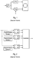
- Digital oscilloscopes exist according to Fig. 1 from an input amplifier whose variable amplification factor matches the amplitude of the measuring signal to be displayed on the oscilloscope to the measuring range of the oscilloscope, a subsequent analog-to-digital converter for generating samples of the digitized measuring signal, a recording unit for displaying the sampled values of the digitized measuring signal and a trigger system connected in parallel to the analog-to-digital converter for the phase or time-correct representation of the signal section of the measurement signal in the recording unit identified with the trigger threshold of the analog trigger system.
- an analog trigger system in Fig. 2 - For simplicity, the triggering in the trigger system of Fig. 2 used only one measurement signal - compared to form more complex trigger conditions via a plurality of comparators the voltage applied to the respective input A, preamplified in amplitude with a measured at the input B each threshold signal on level overrun or underrun.
- the adjustable threshold values 1... N are stored in digitized form in each case in a register.
- a trigger signal for the correct representation of the desired signal section of the measurement signal in the recording unit is generated as a function of the respectively set trigger condition and when the trigger condition occurs.
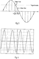
- intersection of the threshold signal with the measurement signal to be recorded-trigger point- is between two samples of the digitized measurement signal to be recorded, the result is as follows Fig. 3 between the trigger point and the next sample or between the trigger point and the previous sample of the digitized measurement signal to be recorded a trigger offset.
- This trigger offset results in the representation of the measurement signal in the recording unit to a phase shift between the recorded measurement signal and the origin of the recording unit.
- phase offset - jitter - between the recording signal to be recorded and the coordinate origin of the recording unit is also known in analog oscilloscopes and in Fig. 4 shown.
- Fig. 4 For a trigger threshold of 0 V, a jitter of 0.3 display units can be seen on the screen of the oscilloscope.
- this jitter is either a constant value - systematic jitter - if the distance between the trigger point and the next sample of the digitized measurement signal is largely unchanged in the case of stationary conditions, or a statistical value - statistical jitter - assume when the measurement signal, for example, a stochastic phase noise is superimposed.
- phase errors in the display of the oscilloscope resulting from the temporal discretization of the measurement signal and stochastic phase noise of the measurement signal
- unwanted jitter can also result from different transit times in the measurement channels of measurement signals, which in combination with the Checking the trigger condition. It can also be disadvantageous that the trigger condition does not occur at all and therefore the measurement signals are not even displayed on the screen of the oscilloscope.
- a compensation of these phase errors by means of calibration is eliminated in many cases.
- a trigger signal generator for an oscilloscope emerges, which generates the trigger signal by digital means.
- the invention has for its object to provide a trigger method, a trigger system and a corresponding digital oscilloscope, the one corresponding to the selected trigger condition, safe triggering the recording of one or more measurement signals on the display unit of the oscilloscope with respect to the sampling rate used in the digital oscilloscope Analog-to-digital converter guarantees higher temporal resolution.
- a digital trigger system used.
- the sampling values of the digitized measurement signal serving as the reference signal are successively compared with a threshold value. If the threshold value is exceeded by the digitized reference signal within two sample values - first sample value ⁇ threshold value, second sample value> threshold value or undershooting of the threshold signal by the digitized reference signal - first sample value> threshold value, second sample value ⁇ threshold value the exact trigger time in a first embodiment of the invention by calculating a plurality of additional samples of the reference signal, which are equidistant from each other between the two sampling times, and re-comparing all additional samples of the reference signal with the threshold to overshoot or undercut the exact Time of exceeding or falling below the threshold determined by the reference signal.
- an occurring trigger offset corresponding to the number of selected additional sampled values of the reference signal, which are calculated by means of interpolation, preferably by means of polyphase
- an additional sample of the reference signal is iteratively added the center of the time interval considered in the respective iteration step is calculated by means of interpolation with polyphase filter and a comparison is made with a threshold value with respect to overshoot or undershoot. Starting from the result of the comparison - overrun or underrun - will be in the next Iteration step that continues to use the halved time interval left or right of the respective additional sample of the reference signal.
- an additional sample of the reference signal in the time interval of the last iteration step is calculated by means of linear interpolation.
- a fourth embodiment of the invention to calculate additional samples of the reference signal between the two sampling times by means of interpolation with polyphase filter to identify a possible exceeding or falling below the threshold by two consecutive (additional) samples of the reference signal.
- a fifth embodiment of the invention by iterative halving of the time interval, then calculating an additional sample of the reference signal in the middle of the respective time interval and comparing the additional sample of the reference signal Reference signal with the threshold significantly minimizes the number of calculations to be performed compared to the fourth embodiment of the invention.
- a comparison with two thresholds - equivalent to a comparator with hysteresis - is performed. In case of exceeding the upper threshold value is used, while in case of falling below the lower threshold value is used.
- Different transit times in the measurement channels belonging to the individual measurement signals are detected via a calibration process and compensated according to the invention for the individual measurement signals, before the reference signal from the individual measurement signals for the digital triggering is determined or before the samples of the individual measurement signals on the screen of the Oscilloscope are displayed.
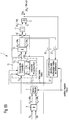
- the inventive digital oscilloscope in Fig. 5 performs with a preamplifier 1, which has a variable gain factor, a level adjustment of the amplitude of the voltage applied to its input measurement signals to the measuring range of the display device 5 by.
- the preamplified analog measurement signals are fed to an analog-to-digital converter 2 for conversion into a corresponding digital data format.
- a subsequent unit for compensation of transit times 3 compensates for different transit times in the measurement channels belonging to the individual measurement signals.
- a equalization system 4 which performs an equalization of the linear or non-linearly distorted digitized measurement signals.
- the linear or non-linear distortions of the measurement signals result from the transmission behavior of the transmission elements of the entire measuring channel (measuring heads, measuring leads, preamplifiers and analog-to-digital converters).
- the digitized measurement signal is checked by a digital trigger system 5 according to the invention with regard to an adjustable trigger condition, and Upon identification of this trigger condition, a trigger signal for triggering the digital oscilloscope at the output of the digital trigger system 5 is generated on the measurement signal. Those samples of the digitized equalized measurement signal are displayed on a screen of the digital oscilloscope recording unit 6, which are detected simultaneously with the trigger signal or immediately after the trigger signal.
- FIGS. 7A, 7B . 7C and 7D The drawing, the first, second, third and fourth embodiment of a system according to the invention for digital triggering will be described below with reference to the FIGS. 6A . 6B and 6C the first, second and third embodiment of a trigger signal generating unit inherent in all of these embodiments of a digital triggering system according to the invention are presented:
- a signal S i from a plurality of signals S to be displayed in a digital oscilloscope is used as the reference signal S i to generate a trigger signal S TR .
- the sampled values S i, j of the reference signal S i and a threshold value SW i are each fed to an input of a comparator 8.
- the comparator 8 compares the sample value S i, j of the digitized reference signal S i with the threshold value SW i and activates a first output in the case of exceeding the threshold value SW i by the sample value S i, j of the reference signal S i or a second output in the case of falling below the threshold value SW i by the sample value S i, j of the reference signal S i .
- downstream edge detector 9 is a positive or negative depending Edge triggering and the two signals at the two outputs of the comparator 8, an overshoot or undershooting of the threshold SW i by two consecutive samples S i, j and S i, j + 1 of the reference signal S i by activating the output of the edge detector. 9 identified.
- the samples S i, j of the reference signal S i are supplied to a unit 13 for determining additional samples S i 'of the reference signal S i , which are equidistant between two successive samples S i, j and S i, j-1 .
- This unit 13 consists of the actual interpolator 13 2 , which is preferably a polyphase filter, and a unit 13 1 for controlling the interpolator.
- the unit 13 1 for controlling the interpolator reads in the individual samples S i, j of the reference signal S i cyclically and stores them between.
- the case of exceeding or falling below the threshold value SW i by two successive samples S i, j and S i, j-1 of the reference signal S i-activated output signal of the edge detector 9 serves the unit 13 1 for controlling the interpolator for sequential transfer of a determined number of read and latched samples S i, j of the reference signal S i , which are the upstream edge event upstream or downstream, to the interpolator 13 second
- the unit 13 1 for controlling the interpolator passes the interpolator 13 2 belonging to calculate the respective additional sample S i, j 'of the reference signal S i filter coefficients K i.
- the polyphase filter 13 2 respectively calculated additional sample S i, j 'of the reference signal S i is read by the unit 13 1 for controlling the interpolator and buffered. If all additional samples S i, j 'of the reference signal S i have been calculated by interpolator 13 2 , unit 13 1 for controlling the interpolator gives them all calculated and cached additional samples S i 'of the reference signal S i off.
- the additional samples S i 'of the reference signal S i are read in a subsequent comparator 14 and compared in each case with the threshold value SW i .
- the comparator 14 has two outputs, one of which outputs when the threshold value SW i is exceeded by the additional sampled value S i, j ' of the reference signal S i is activated, and the other output is activated in each case falls below the threshold value SW i by the additional sample value S i, j 'of the reference signal S i .
- a final evaluation logic 15 determines, as a function of a positive or negative edge triggering and the signals present at the individual outputs of the comparator 14 those additional sample S i, j 'of the reference signal S i , which has the shortest distance to the threshold SW i and the sought Trigger time for the trigger signal S TR represents.
- FIGS Fig. 6B A second embodiment 7 'of a trigger signal generation unit is described which requires a minimized number of additional samples S i ' of the reference signal S i for the determination of the trigger instant.
- the second embodiment 7 'of the trigger signal generation unit compares the individual samples S i, j of the first embodiment 7 of the trigger signal generation unit in a comparator 8' Reference signal S i , which is selected from a plurality of signals to be displayed on the digital oscilloscope S , with the threshold SW i .
- the comparison leads to an activation of a first output of the comparator 8 'in the event of exceeding the threshold value SW i by two consecutive samples S i, j and S i, j-1 of the reference signal S i and to an activation of a second one Output of the comparator 8 'in the case of falling below the threshold SW i by two consecutive samples S i, j and S i, j-1 of the reference signal S i .
- An edge detector 9 'following the comparator 8' determines, from the two signals present at the first or second output of the comparator 8 ', whether, depending on a positive or negative edge triggering, the threshold value SW i is exceeded or undershot by two successive sampled values S i, j and S i, j-1 of the reference signal S i is present and activated in case of exceeding or falling short of the output of the edge detector 9 '.
- the samples S i, j of the reference signal S i are supplied to a unit 13 'for determining additional samples S i ' of the reference signal S i located between two successive samples S i, j and S i, j-1 .
- This unit 13 ' consists of the actual interpolator 13 2 ', which is preferably a polyphase filter, and a unit 13 1 'for controlling the interpolator.
- the additional sample S i, j 'of the reference signal S i is in the middle by means of interpolation in a polyphase filter based on the first embodiment in the first iteration step of the time interval determined by the two samples S i, j and S i, j-1 of the reference signal respectively upstream and downstream of the identified edge event S i is determined.
- the unit 13 for determining additional samples S i 'of the reference signal S i determines the additional sample S i, j ' of the reference signal S i in the middle of the time interval determined by the preceding iteration step j-1.
- the additional sampled value S i, j ' of the reference signal S i determined in the iteration step j is compared with the threshold value SW i for overshooting or undershooting, and if the threshold value SW i is exceeded by the additional sampled value S i, j 'of the reference signal S i a first output and when falling below the threshold SW i by the additional sample S i, j ' of the reference signal S i, a second output is activated.
- the additional sample value S i, j 'of the reference signal S i and the threshold value SW i determined in the unit 13' for determining additional sampled values S i 'of the reference signal S i in the iteration step j becomes the level spacing in a subtracter 16' formed between the additional sample S i, j 'of the reference signal S i and the threshold SW i , and forwarded to a subsequent absolute value generator 17'.
- the determined amount of the level difference between the additional sample value S i, j ' of the reference signal S i and the threshold value SW i is compared with a limit value G.
- an additional sample value S i, j 'of the reference signal S i is identified, which is closest to the trigger point and thus forms the trigger instant of a trigger signal S TR generated at the output of the comparator 18'.
- the two switches 19 'and 20' are closed and the two at the output of the comparator 14 'applied signals, each exceeding or falling below the threshold SW i by the iterated in the iteration step j additional sample S i, j 'of the reference signal S i , the unit 21' forwarded to determine the left or right side halved time interval.
- the unit 21' determines the time interval halved on the left or right side determined additional sample S i, j 'of the reference signal S i left or right half located in the iteration step j considered time interval for the determination of the additional sample S i, j + 1 ' of the reference signal S i in the next iteration step j + 1 determined ,
- the information about the left or right half of the time interval of the current iteration step j used in the next iteration step j + 1 is given by the unit 21 'for determining the left or right half time interval of the unit 13 1 ' for controlling the interpolator of the unit 13 '. for the determination of additional samples S i 'of the reference signal S i .
- the second embodiment of the trigger signal generation unit leads compared to the first embodiment of the trigger signal generation unit to a minimized number of additional samples S i 'of the reference signal S i .
- the third embodiment 7 "of the trigger signal generation unit according to the invention in FIG Fig. 6C is based on the second embodiment 7 'of the trigger signal generation unit according to the invention in FIG Fig. 6B in that, in the last iteration step j + 1, as soon as the magnitude of the level difference between the additional sampled value S i, j 'of the reference signal S i and the threshold value SW i determined in the iteration step j falls below a limit value G, then via a linear interpolation in the two previous iteration steps j and j-1 additional samples S i, j 'and S i, j-1 ' of the reference signal S i an additional sample S i, j + 1 'of the reference signal S i is determined whose time value represents the sought trigger time for the trigger signal S TR .
- the third embodiment 7 "of the trigger signal generation unit according to the invention in FIG Fig. 6C has for this purpose the identical functional units to the second embodiment 7 'of the trigger signal generating unit according to the invention (reference numerals 8''to21'').
- the unit 13 '' for controlling the interpolator of the unit 13 '' to determine additional samples S i 'of the reference signal S i cached additional samples S i, j ' and S i, j-1 'of the reference signal S.
- the linear interpolator 25 "determines from the additional samples S i, j 'and S i, j-1 ' of the reference signal S i and their associated sampling times and the threshold SW i via a linear interpolation a the intersection between threshold SW i and reference signal S i in "Near range” as the trigger time of the trigger signal S TR ".
- FIGS. 6A . 6B and 6C The first, second and third embodiments 7, 7 ', 7 "of the trigger signal generation unit according to the invention are described below in FIGS FIGS. 7A, 7B . 7C and 7D presented the first, second, third and fourth embodiment 5, 5 ', 5''and5''' of the digital triggering system according to the invention:
- a first embodiment 5 of the inventive system for digital triggering in Fig. 7A In order to form a reference signal S i , a plurality of signals S 1 , S 2 ,..., S M are linked from all the signals S to be displayed on the digital oscilloscope via a preceding trigger logic 29.
- the reference signal S i is connected to a threshold value SW i in a trigger signal generation unit 7, 7 'or 7 "according to FIG Fig. 6A . 6B and 6C with respect to the determination of a comparatively exact triggering time. With the entry of the comparatively exact trigger time point, a trigger signal S TR is activated at the output of the trigger signal generation unit 7, 7 'or 7 ".
- the preceding trigger link logic 29 may be any of a number of possible arithmetic and logic links.
- a differential signal according to the invention as a reference signal S i .
- the two sub-signals of the measured differential signal in each case with a probe to ground potential, converted by an analog-to-digital converter into a corresponding digital data format and read to form the digital differential signal from the trigger logic logic 29 each and subtracted from each other via a digitally realized difference.
- a second embodiment 5 'of the inventive system for digital triggering in Fig. 7B be used for the triggering signals S 1 , S 2 , ..., S N from all the signals to be represented on the digital oscilloscope S respectively as reference signals in a respective trigger signal generating unit 7 1 , 7 1 ', 7 1 ", 7 2 , 7 2 ', 7 2 ", ..., 7 N , 7 N ', 7 N " in each case with the same threshold value SW i to overflow or underflow to determine an associated trigger time for an associated trigger signal S TR1 , S TR2 , ..., S TRN compared.
- the individual trigger signals S TR1, TR2 S, ..., S TRN linked arithmetically and / or logically to a combined trigger signal S TR.
- the second embodiment 5 'of the inventive system for digital triggering in Fig. 7B is used when each individual signal used for the digital triggering is compared with an identical threshold value for determining a signal-specific trigger time. In this way, a trigger signal can be generated, which in contrast to the first embodiment 5 in Fig. 7A realized on multiple reference signals more complex trigger signal generation.
- the third embodiment 5 "of the inventive system for digital triggering in Fig. 7C represents a combination of the first and second embodiments of the inventive system for digital triggering in Figs. 7A and 7B represents.
- the trigger signals S TRi , S TRM + 1 , S TRM + 2 ,... That are activated at the respectively determined trigger instant are arithmetically and / or logically linked to one another in a subsequent trigger signal combining unit 29 'to form a combined trigger signal S TR .
- the respectively identified trigger time of the individual trigger signal generation units 7 i1 7 i1 ', 7 i1 ", 7 i2 ' 7 i2 ', 7 i2 ", ..., 7 iK , 7 iK ', 7 iK " respectively activated trigger signals S TRi1 , S TRi2 , ..., S TRiK be a subsequent trigger signal combining unit 29 'to a combined trigger signal S. TR with each other arithmetically and / or logically linked.
- the comparison of a single signal S i with a plurality of threshold values SW 1 , SW 2 ,..., SW K according to the invention is also based on a digital trigger system with a plurality of signals S for triggering in the sense of the second and third embodiments 5 'and 5 " inventive system for digital triggering in Fig. 7B and 7C transferable.
- the two samples S i, j and S i, j-1 of the reference signal S i are identified with the aid of an edge detector 9 from the comparison result of method step S10, between which an exceeding or undershooting of the threshold value SW i the two samples S i, j and S i, j-1 of the reference signal S i takes place.
- the additional samples S i 'of the reference signal S i are calculated which distribute equidistantly between the samples S i, j and S i, j-1 of the reference signal S i identified in method step S20 are.
- the number of additional samples S i 'of the reference signal S i used in this case determines the accuracy of the trigger time point determined in the following method steps.
- the additional sampled values S i 'of the reference signal S i determined in method step S30 between the two sampled values S i, j and S i, j-1 of the reference signal S i identified in method step S20 become the comparator in the subsequent method step S40 14 compared to exceeding or falling below the threshold SW i .
- Fig. 11A shows an example of a sinusoidal signal which serves as reference signal S i, and a threshold value SW i, as with the first embodiment of the method according to the invention the trigger signal generating by calculating equidistant additional sampled values S i , 1 ', S i, 2 ' , S i, 3 ', S i, 4 ', S i, 5 ',... between two sampling points of the sinusoidal signal whose level is in each case and above the level of the threshold value, the additional sample value S i, 3 'of the reference signal S i , which has a minimum distance to the threshold value SW i , is determined as the trigger time for a trigger signal.
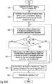
- the second embodiment of the inventive method for digital trigger signal generation in Fig. 8B has in its first two steps S100 and S110 to the process step S10 and S20 of the first embodiment of the inventive method for digital trigger signal generation in Fig. 8A identical procedure.
- the additional sample value S i, j 'of the reference signal S i is calculated in the middle of a time interval belonging to the first iteration step by means of interpolation in the first iteration step, the two limits of the time interval belonging to the first iteration step the two in method step S110 identified samples S i, j ' S i, j-1 of the reference signal S i are, between which an overshoot or undershooting of the threshold value SW i by the reference signal S i .
- the respective limits of the time interval are determined by the left or right-hand boundary of the time interval considered in the preceding iteration step j-1 and a sample value S i, j-1 of the reference signal S i determined in the preceding iteration step j-1 which is positioned at the time interval center of the time interval considered in the preceding iteration step j-1.
- the distance of the additional sample value S i, j 'of the reference signal S i determined in method step S120, which is positioned in the middle of the time interval considered in the respective iteration step j, is calculated as the threshold value SW i .
- the additional sample value S i, j 'of the reference signal S i and the threshold value SW i is compared with the threshold value SW i for overshoot or undershoot in method step S150.
- the time interval to be considered in the following iteration step j + 1 is determined in the following method step S160.
- the half of the time interval considered in the iteration step j considered by the additional sample S i, j 'of the reference signal S i considered in method step S120 is followed up in the following iteration step j + 1, if the additional sample value S i, j is selected for a selected positive edge triggering 'of the reference signal S i i exceeds the threshold value SW or at a selected negative Edge triggering of the additional sampled S i, j 'of the reference signal S i to the threshold value SW i below.
- the half of the time interval considered in the iteration step j considered by the additional sampling value S i, j 'of the reference signal S i considered in method step S120 is traced further in the following iteration step j + 1 if the additional sampling value S i is selected for a selected positive edge triggering .
- j 'of the reference signal S i to the threshold value SW i is less than or S i, j at a selected negative edge triggering of the additional sampled' of the reference signal S i exceeds the threshold value SW i.
- the additional sample value S i, j + 1 'of the reference signal S i in the middle of the time interval considered in the iteration step j + 1 is determined by means of interpolation.
- step S140 the comparison of the level difference between the additional sample value S i, j 'of the reference signal S i and the threshold value SW i with a predetermined limit value G in method step S140 results in the limit value G being undershot by the level difference between the additional sample value S i, j 'of the reference signal S i and the threshold value SW i , the iteration method is ended and in step S170 the additional sample value S i, j ' of the reference signal S i determined in the current iteration step j is selected as the desired trigger time for the trigger signal S TR '. established.
- Fig. 11B shows the example of a sinusoidal signal and a predetermined threshold, as with the aid of the second embodiment of the inventive method for trigger signal generation by iterative determination of additional samples S i, 1 ', S i, 2 ' and S i, 3 'of the additional sample S i, 3 'of the reference signal S i , which has the minimum distance to the threshold, is determined as the trigger time of the trigger signal.
- the third embodiment of the inventive method for trigger signal generation in Fig. 6C which is the second embodiment of the inventive method for trigger signal generation in Fig. 6B extends, includes in their process steps S200, S210, S220, S230, S240, S250 and S260, the process steps S100, S110, S120, S130, S140, S150 and S160 of the second embodiment of the inventive method for trigger signal generation.
- step S270 on the basis of the additional samples S i, j 'and S i, j-1 ' of the reference signal S i and their associated sampling times determined in the last two iteration steps j and j-1 and of the threshold value SW i calculated by means of linear interpolation, the intersection between threshold SW i and reference signal S i as a more precise trigger time of the trigger signal S TR ".
- step S300 of the first embodiment of the inventive method for digital triggering in Fig. 9A A plurality of signals S 1 , S 2 ,..., S M from all signals S to be displayed on the digital oscilloscope, which are used for the triggering, are arithmetically and / or logically linked together in a trigger logic 29.
- the reference signal S i is determined using the first, second or third embodiment of the trigger signal generation method according to the invention Fig. 8A . 8B and 8C With a threshold value SW i in a trigger signal generating unit 7, 7 'or 7 "compared and determined from the comparison result, a trigger signal S TR with a correct trigger time without trigger offset.
- a plurality of signals S 1 , S 2 ,..., S M from all the signals S to be displayed on the digital oscilloscope used for the triggering are respectively individually using the first, second or third embodiment of the triggering signal generation method according to the invention according to Fig. 8A . 8B and 8C with a threshold SW i in a trigger signal generating unit 7, 7 'or 7 "compared and generates from the comparison result in each case a trigger signal S TR1 , S TR2 , ..., S TRN with a correct trigger time without trigger offset.
- the trigger signals S TR1 , S TR2 ,..., S TRN respectively generated in method step S400 are subsequently linked together in method step S410 in a trigger signal combining unit 29 'to form a combined trigger signal S TR .
- the third embodiment of the method according to the invention for digital triggering in Fig. 9C as a combination of the first and second embodiment of the inventive method for digital triggering in Figs. 9A and 9B contains in its first method step S500 the method step S300 of the first embodiment of the inventive method for digital triggering in Fig. 9A and in the following method steps S510 and S520, the method steps S400 and S410 of the second embodiment of the inventive method for digital triggering in Fig. 9B ,
- a signal S i provided for the triggering is selected from all signals S to be displayed on the digital oscilloscope using the first, second or third embodiment of the inventive method for digital trigger signal generation according to FIG Fig. 8A . 8B and 8C each with a different threshold SW 1 , SW 2 , ..., SW K in each case a trigger signal generating unit 7, 7 'or 7 "compared and from the comparison result in each case a trigger signal S TR1 , S TR2 , ..., S TRN generated with a correct trigger time without trigger offset.
- the trigger signals S TR1 , S TR2 ,..., S TRN respectively generated in method step S600 are linked to one another in the subsequent method step S610 in a trigger signal combination unit 29 'to form a combined trigger signal S TR .
- the reference signal S i between the two successive sampled values S i, j ' S i, j-1 falls below the threshold SW i due to a sampling rate which is too low, without triggering being effected.
- the first, second and third embodiment of the method according to the invention for trigger signal generation in the Fig. 8A . 8B and 8C used to uniquely identify over or under the threshold value SW i by the reference signal S i via the determination of additional samples S i, j "between the two successive samples S i, j and S i, j-1 or clearly not to be identified
- the fourth, fifth and sixth embodiment of the method according to the invention for trigger signal generation developed therefrom is disclosed in US Pat Fig. 10a . 10B and 10C shown.
- the fourth embodiment of the inventive method for trigger signal generation in Fig. 10A in its first method step S700 corresponds to the first method step S10 of the first embodiment.
- the following second method step S710 of the fourth embodiment in contrast to the second method step S20 of the first embodiment, examines whether two consecutive samples S i, j and S i, j-1 of the reference signal S i are respectively below or above the threshold value SW i ,
- a trigger event is identified, then in method step S760 a trigger signal S TR '"is generated, which is activated with the identified trigger time.
- Fig. 12A shows for a sinusoidal reference signal S i and a given threshold SW i the equidistant additional samples S i, 1 ", S i, 2 " and S i, 3 "of the reference signal S i between the two samples S i, j and S i, j-1 of the reference signal S i , whose levels are both below the threshold, and the additional sample S i, 3 '' identified as the trigger point.
- the fifth embodiment of the inventive method for trigger signal generation in Fig. 10B in its first method step S800 corresponds to the first method step S100 of the second embodiment.
- method step S810 of the fifth embodiment in contrast to method step S110 of the second embodiment, two consecutive samples S i, j and S i, j-1 of the reference signal S i are identified, which are either either below or above the threshold value SW i .
- step S820 an additional sample S i, j "of the Reference signal S i calculated by means of interpolation, which is located in the middle of the time interval considered in the respective iteration step.
- the time interval between the consecutive samples S i, j and S i, j-1 of the reference signal S i is considered.
- step S830 it is checked whether the consecutive samples S i, j and S i, j-1 and the additional sample S i, j "of the reference signal S i determined in the current iteration step are all above or all below the threshold value SW i lie.
- an additional sample value S i, j "of the reference signal S i must be determined within a time interval that is within the time interval of the current iteration step and halved relative thereto.
- that halved time interval which is located either at the left or at the right-hand side relative to the additional sample value S i, j "of the reference signal S i determined in the current iteration step is selected, which is between the sample value S i, j and S i , j-1 and the additional sample S i, j "of the reference signal S i determined in the current iteration step, which has the shorter level distance from the threshold value SW i .
- an exceeding or falling below the threshold value SW i by the reference signal S i uniquely identified or unambiguously unidentified (due to frequency limitation of the reference signal S i due to the sampling theorem).
- Method step S850 essentially comprises the method steps S120 to S160 of the second embodiment of the method according to the invention for trigger signal generation in Fig. 8B ,
- a trigger signal S TR "" is generated on the basis of the trigger time determined in method step S850.
- Fig. 12B is the approximation of the additional samples S i, 1 ", S i, 2 " and S i, 3 "of the reference signal S i to the trigger point (additional sample S i, 3 ") with the aid of the fifth embodiment of the inventive method for trigger signal generation on the basis of an iterative time interval halving shown.
- a sixth embodiment of the inventive method for generating trigger signal is shown, whose method steps S800 to S850 the method steps S900 to S950 of the fifth embodiment of the inventive method for trigger signal generation in Fig. 10A correspond.
- method step S960 of the sixth embodiment in analogy to method step S270 of the third embodiment, by means of linear interpolation between the time interval considered in the last iteration step of method step S950 with its time interval limits-the additional samples S i, j "and S i determined in the last two iteration steps , j + 1 '' of the reference signal S i - calculates a more precise trigger time as an intersection between the threshold value SW i and the reference signal S i .
- a trigger signal S TR "'" is generated on the basis of the trigger time point determined in method step S960.
- the invention is not limited to the illustrated embodiments.
- other interpolation methods are also covered by the invention.
Landscapes
- Physics & Mathematics (AREA)
- General Physics & Mathematics (AREA)
- Analogue/Digital Conversion (AREA)
Abstract
Die Erfindung betrifft ein Verfahren und ein System zur digitalen Triggerung einer Aufzeichnung eines oder mehrerer digitalisierter Signale ( S ) auf einem digitalen Oszilloskop, indem zur Bestimmung eines Triggerzeitpunkts jeweils zwischen zwei aufeinander folgenden Abtastwerten (S i,j , S i,j-1 ) eines Referenz-Signals (S i ) und einem Schwellwert (SW i ) ein Pegelvergleich durchgeführt wird. Zwischen zwei aufeinander folgenden Abtastwerten (S i,j , S i,j-1 ) des Referenz-Signals (S i ) wird mindestens ein zusätzlicher Abtastwert (S i,j ', S i,j ") des Referenz-Signals (S i ) mittels Interpolation ermittelt.The invention relates to a method and a system for the digital triggering of a recording of one or more digitized signals (S) on a digital oscilloscope, in each case between two consecutive samples (S i, j, S i, j-1) for determining a trigger instant. a reference signal (S i) and a threshold value (SW i), a level comparison is performed. Between at least one additional sample (S i, j ', S i, j ") of the reference signal (S i) determined by means of interpolation.
Description
Die Erfindung betrifft ein Verfahren und ein System zur digitalen Triggerung für Oszilloskope und entsprechendes digitales Oszilloskop.The invention relates to a method and a system for digital triggering for oscilloscopes and corresponding digital oscilloscope.
Digitale Oszilloskope bestehen gemäß
Ein analoges Triggersystem in
Befindet sich der Schnittpunkt des Schwellwertsignals mit dem aufzuzeichnenden Messsignal - Trigger-Punkt - zwischen zwei Abtastwerten des digitalisierten aufzuzeichnenden Messsignals, so ergibt sich gemäß
Dieser Phasenversatz - Jitter - zwischen dem aufzuzeichenenden Messsignal und dem Koordinatenursprung der Aufzeichnungseinheit ist auch bei analogen Oszilloskopen bekannt und in
Von analogen Oszilloskopen ist bekannt, dass dieser Jitter entweder einen konstanten Wert - systematischer Jitter - , wenn der Abstand zwischen dem Trigger-Punkt und dem nächsten Abtastwert des digitalisierten Messsignals im Fall von stationären Verhältnissen weitestgehend unverändert ist, oder einen statistischen Wert - statistischer Jitter - annehmen, wenn dem Messsignal beispielsweise ein stochastisches Phasenrauschen überlagert ist.From analog oscilloscopes it is known that this jitter is either a constant value - systematic jitter - if the distance between the trigger point and the next sample of the digitized measurement signal is largely unchanged in the case of stationary conditions, or a statistical value - statistical jitter - assume when the measurement signal, for example, a stochastic phase noise is superimposed.
Neben diesen aus der zeitlichen Diskretisierung des Messsignals und stochastischem Phasenrauschen des Messsignals resultierenden Phasenfehlern in der Anzeige des Oszilloskops können unerwünschte Jitter auch aus unterschiedlichen Laufzeiten in den Messkanälen von Messsignalen resultieren, welche in Kombination zur Überprüfung der Triggerbedingung herangezogen werden. Hierbei kann es auch nachteilig vorkommen, dass die Triggerbedingung überhaupt nicht eintritt und deshalb die Messsignale erst gar nicht auf dem Bildschirm des Oszilloskops dargestellt werden.In addition to these phase errors in the display of the oscilloscope resulting from the temporal discretization of the measurement signal and stochastic phase noise of the measurement signal, unwanted jitter can also result from different transit times in the measurement channels of measurement signals, which in combination with the Checking the trigger condition. It can also be disadvantageous that the trigger condition does not occur at all and therefore the measurement signals are not even displayed on the screen of the oscilloscope.
Zusätzlich nachteilig kann die Tatsache gewertet werden, dass Phasen- bzw. Zeitfehler in den beiden Pfaden des Messsignals - Analog-Digital-Wandler bzw. Triggersystem - sich gegenseitig überlagern und im Extremfall eine Verdopplung der Wirkung hervorrufen. Eine Kompensation dieser Phasenfehler mittels Kalibrierung scheidet vielfach aus.Additionally detrimental may be the fact that phase or time errors in the two paths of the measurement signal - analog-to-digital converter or trigger system - overlap each other and in the extreme case cause a doubling of the effect. A compensation of these phase errors by means of calibration is eliminated in many cases.
Aus der
Der Erfindung liegt die Aufgabe zugrunde, ein Triggerverfahren, ein Triggersystem und ein entsprechendes digitales Oszilloskop zu schaffen, das eine der gewählten Triggerbedingung entsprechende, sichere Triggerung der Aufzeichnung eines oder mehrerer Messsignale auf der Anzeigeeinheit des Oszilloskops mit einer gegenüber der Abtastrate des im digitalen Oszilloskop verwendeten Analog-Digital-Wandlers höheren zeitlichen Auflösung garantiert.The invention has for its object to provide a trigger method, a trigger system and a corresponding digital oscilloscope, the one corresponding to the selected trigger condition, safe triggering the recording of one or more measurement signals on the display unit of the oscilloscope with respect to the sampling rate used in the digital oscilloscope Analog-to-digital converter guarantees higher temporal resolution.
Die Aufgabe wird bezüglich des Verfahrens durch die Merkmale des Anspruchs 1, bezüglich des Triggersystems durch die Merkmale des Anspruchs 18 und bezüglich des Oszilloskops durch die Merkmale des Anspruchs 21 gelöst. Die Unteransprüche enthalten vorteilhafte Weiterbildungen der Erfindung.The object is achieved with respect to the method by the features of
Anstelle der analogen Triggerung und der damit verbundenen Nachteile wird erfindungsgemäß ein digitales Triggersystem verwendet. Hierbei werden während des Triggervorgangs nacheinander die Abtastwerte des als Referenz-Signal dienenden digitalisierten Messsignals mit einem Schwellwert verglichen. Liegt innerhalb zweier Abtastwerte eine Überschreitung des Schwellwerts durch das digitalisierte Referenz-Signal - erster Abtastwert < Schwellwert, zweiter Abtastwert > Schwellwert- oder eine Unterschreitung des Schwellwertsignals durch das digitalisierte Referenz-Signal - erster Abtastwert > Schwellwert, zweiter Abtastwert < Schwellwert -, so wird der exakte Triggerzeitpunkt in einer ersten Ausführungsform der Erfindung durch Berechnung mehrerer zusätzlicher Abtastwerte des Referenz-Signals, die zwischen den beiden Abtastzeitpunkten in äquidistanten Abstand zueinander liegen, und erneuten Vergleich aller zusätzlichen Abtastwerte des Referenz-Signals mit dem Schwellwert auf Über- oder Unterschreitung der exakte Zeitpunkt des Über- oder Unterschreitens des Schwellwerts durch das Referenz-Signal ermittelt. Auf dieses Weise kann erfindungsgemäß ein auftretender Trigger-Offset entsprechend der Anzahl gewählter zusätzlicher Abtastwerte des Referenz-Signals, die mittels Interpolation - bevorzugt mittels Polyphasenfilter - berechnet werden, minimiert werden.Instead of the analog triggering and the associated disadvantages according to the invention a digital trigger system used. During the triggering process, the sampling values of the digitized measurement signal serving as the reference signal are successively compared with a threshold value. If the threshold value is exceeded by the digitized reference signal within two sample values - first sample value <threshold value, second sample value> threshold value or undershooting of the threshold signal by the digitized reference signal - first sample value> threshold value, second sample value <threshold value the exact trigger time in a first embodiment of the invention by calculating a plurality of additional samples of the reference signal, which are equidistant from each other between the two sampling times, and re-comparing all additional samples of the reference signal with the threshold to overshoot or undercut the exact Time of exceeding or falling below the threshold determined by the reference signal. In this way, according to the invention, an occurring trigger offset corresponding to the number of selected additional sampled values of the reference signal, which are calculated by means of interpolation, preferably by means of polyphase filters, can be minimized.
Um die Anzahl der zu berechnenden zusätzlichen Abtastwerte des Referenz-Signals zu minimieren und damit eine laufzeitoptimierte Triggerung zu realisieren, wird in einer zweiten Ausführungsform der Erfindung anstelle einer festen Anzahl von zusätzlichen Abtastwerten des Referenz-Signals iterativ jeweils ein zusätzlicher Abtastwert des Referenz-Signals in der Mitte des im jeweiligen Iterationsschritt betrachteten Zeitintervalls mittels Interpolation mit Polyphasenfilter berechnet und ein Vergleich mit einem Schwellwert hinsichtlich Über- oder Unterschreitung durchgeführt. Ausgehend vom Ergebnis des Vergleichs - Über- oder Unterschreitung - wird im nächsten Iterationsschritt das vom jeweiligen zusätzlichen Abtastwert des Referenz-Signals links- oder rechtsseitig liegende halbierte Zeitintervall weiterverwendet.In order to minimize the number of additional samples of the reference signal to be calculated and thus to realize runtime-optimized triggering, in a second embodiment of the invention, instead of a fixed number of additional samples of the reference signal, an additional sample of the reference signal is iteratively added the center of the time interval considered in the respective iteration step is calculated by means of interpolation with polyphase filter and a comparison is made with a threshold value with respect to overshoot or undershoot. Starting from the result of the comparison - overrun or underrun - will be in the next Iteration step that continues to use the halved time interval left or right of the respective additional sample of the reference signal.
Schließlich wird in einer dritten Ausführungsform der Erfindung nach iterativer Halbierung der Zeitintervalle entsprechend der zweiten Ausführungsform der Erfindung ein zusätzlicher Abtastwert des Referenz-Signals im Zeitintervall des letzten Iterationsschritts mittels linearer Interpolation berechnet.Finally, in a third embodiment of the invention, after iterative halving of the time intervals according to the second embodiment of the invention, an additional sample of the reference signal in the time interval of the last iteration step is calculated by means of linear interpolation.
Wird ein Triggerzeitpunkt zwischen jeweils zwei aufeinander folgenden Abtastwerten des digitalisierten Messsignals aufgrund fehlender Über- oder Unterschreitung des Schwellwerts durch das Referenz-Signal fehlerhaft nicht identifiziert (Schwellwert liegt entweder oberhalb oder unterhalb von beiden aufeinander folgenden Abtastwerten des Referenz-Signals), so sind erfindungsgemäß in einer vierten Ausführungsform der Erfindung zusätzliche Abtastwerte des Referenz-Signals zwischen den beiden Abtastzeitpunkten mittels Interpolation mit Polyphasenfilter zu berechnen, um ein mögliches Über- oder Unterschreiten des Schwellwerts durch zwei aufeinanderfolgende (zusätzliche) Abtastwerte des Referenz-Signals zu identifizieren.If a trigger time point between in each case two consecutive samples of the digitized measurement signal is incorrectly not identified due to missing or not exceeding the threshold value by the reference signal (threshold value is either above or below both consecutive samples of the reference signal), then according to the invention a fourth embodiment of the invention to calculate additional samples of the reference signal between the two sampling times by means of interpolation with polyphase filter to identify a possible exceeding or falling below the threshold by two consecutive (additional) samples of the reference signal.
Um die Anzahl von zu berechnenden zusätzlichen Abtastwerten des Referenz-Signals zu minimieren, werden in einer fünften Ausführungsform der Erfindung durch iterative Halbierung des Zeitintervalls, anschließende Berechnung eines in der Mitte des jeweiligen Zeitintervalls befindlichen zusätzlichen Abtastwerts des Referenz-Signals und Vergleich des zusätzlichen Abtastwerts des Referenz-Signals mit dem Schwellwert die Anzahl durchzuführender Berechnungen gegenüber der vierten Ausführungsform der Erfindung deutlich minimiert.In order to minimize the number of additional samples of the reference signal to be calculated, in a fifth embodiment of the invention by iterative halving of the time interval, then calculating an additional sample of the reference signal in the middle of the respective time interval and comparing the additional sample of the reference signal Reference signal with the threshold significantly minimizes the number of calculations to be performed compared to the fourth embodiment of the invention.
Analog zur dritten Ausführungsform der Erfindung gibt es auch eine sechste Ausführungsform, in der im letzten Iterationsschritt der zusätzliche Abtastwert des Referenz-Signals mittels linearer Interpolation aus den in den beiden vorhergehenden Iterationsschritten durch Interpolation mittels Polyphasenfilter berechneten zusätzlichen Abtastwerten des Referenz-Signals bestimmt wird.Analogously to the third embodiment of the invention, there is also a sixth embodiment in which in the last iteration step the additional sample of the reference signal is determined by means of linear interpolation from the additional samples of the reference signal calculated in the two preceding iteration steps by interpolation by means of polyphase filter.
Um die Empfindlichkeit des Triggersystems zu reduzieren, wird ein Vergleich mit zwei Schwellwerten - entspricht einem Komparator mit Hysterese - durchgeführt. Im Fall einer Überschreitung wird der obere Schwellwert verwendet, während im Fall der Unterschreitung der untere Schwellwert Verwendung findet.In order to reduce the sensitivity of the trigger system, a comparison with two thresholds - equivalent to a comparator with hysteresis - is performed. In case of exceeding the upper threshold value is used, while in case of falling below the lower threshold value is used.
Unterschiedliche Laufzeiten in den zu den einzelnen Messsignalen gehörigen Messkanälen werden über einen Kalibrierungsvorgang erfaßt und erfindungsgemäß bei den einzelnen Messsignalen kompensiert, bevor das Referenz-Signal aus den einzelnen Messsignalen für die digitale Triggerung ermittelt wird bzw. bevor die Abtastwerte der einzelnen Messsignale auf dem Bildschirm des Oszilloskops dargestellt werden.Different transit times in the measurement channels belonging to the individual measurement signals are detected via a calibration process and compensated according to the invention for the individual measurement signals, before the reference signal from the individual measurement signals for the digital triggering is determined or before the samples of the individual measurement signals on the screen of the Oscilloscope are displayed.
Beispielhafte Ausführungsformen des erfindungsgemäßen Verfahrens und Systems zur digitalen Triggerung für Oszilloskope werden im folgenden unter Berücksichtigung der Zeichnung näher erläutert. In der Zeichnung zeigen:
- Fig. 1
- ein Blockschaltbild eines digitalen Oszilloskops mit einem analogen Triggersystem nach dem Stand der Technik,
- Fig. 2
- ein Blockschaltbild eines analogen Triggersystems nach dem Stand der Technik,
- Fig. 3
- einen Zeitverlauf eines digitalisierten Messsignals mit TriggerOffset,
- Fig. 4
- eine grafische Darstellung einer Anzeigeeinrichtung eines Oszilloskops mit fehlerhaft dargestelltem Messsignal mit analoger Triggerung,
- Fig. 5
- ein Blockschaltbild eines digitalen Oszilloskops mit erfindungsgemäßem digitalen Triggersystem,
- Fig. 6A,6B,6C
- ein Blockschaltbild einer ersten, zweiten und dritten Ausführungsform einer erfindungsgemäßen digitalen Triggersignal-Erzeugungs-Einheit,
- Fig. 7A,7B,7C,7D
- ein Blockschaltbild einer ersten, zweiten, dritten und vierten Ausführungsform eines erfindungsgemäßen Systems zur digitalen Triggerung,
- Fig. 8A,8B,8C
- ein Flußdiagramm einer ersten, zweiten und dritten Ausführungsform eines erfindungsgemäßen Verfahrens zur digitalen Triggersignal-Erzeugung,
- Fig. 9A,9B,9C,9D
- ein Flußdiagramm einer ersten, zweiten, dritten und vierten Ausführungsform eines erfindungsgemäßen Verfahrens zur digitalen Triggerung,
- Fig. 10A,10B,10C
- ein Flußdiagramm der vierten, fünften und sechsten Ausführungsform eines erfindungsgemäßen Verfahrens zur digitalen Triggersignal-Erzeugung,
- Fig. 11A, 11B
- einen Zeitverlauf eines digitalisierten Messsignals gemäß der ersten und zweiten Ausführungsform des erfindungsgemäßen Verfahrens bzw. Systems zur digitalen Triggerung und
- Fig. 12A, 12B
- einen Zeitverlauf eines digitalisierten Messsignals gemäß der vierten und fünften Ausführungsform des erfindungsgemäßen Verfahrens bzw. Systems zur digitalen Triggersignal-Erzeugung.
- Fig. 1
- a block diagram of a digital oscilloscope with a prior art analog trigger system,
- Fig. 2
- a block diagram of an analog trigger system according to the prior art,
- Fig. 3
- a time course of a digitized measurement signal with TriggerOffset,
- Fig. 4
- a graphical representation of a display device of an oscilloscope with erroneously displayed measurement signal with analog triggering,
- Fig. 5
- a block diagram of a digital oscilloscope with inventive digital trigger system,
- Figs. 6A, 6B, 6C
- 1 is a block diagram of a first, second and third embodiment of a digital trigger signal generation unit according to the invention;
- Figs. 7A, 7B, 7C, 7D
- 1 is a block diagram of a first, second, third and fourth embodiment of a digital triggering system according to the invention;
- 8A, 8B, 8C
- a flowchart of a first, second and third embodiment of a method according to the invention for digital trigger signal generation,
- Figs. 9A, 9B, 9C, 9D
- a flowchart of a first, second, third and fourth embodiment of a method according to the invention for digital triggering,
- 10A, 10B, 10C
- a flowchart of the fourth, fifth and sixth embodiment of a inventive method for digital trigger signal generation,
- Figs. 11A, 11B
- a time course of a digitized measurement signal according to the first and second embodiment of the method or system for digital triggering and
- Figs. 12A, 12B
- a time course of a digitized measurement signal according to the fourth and fifth embodiments of the inventive method or system for digital trigger signal generation.
Das erfindungsgemäße digitale Oszilloskop in
Das digitalisierte Messsignal wird nach der Entzerrung von einem erfindungsgemäßen digitalen Triggersystem 5 hinsichtlich einer einstellbaren Triggerbedingung geprüft und bei Identifizierung dieser Triggerbedingung wird am Messsignal ein Triggersignal zur Triggerung des Digitaloszilloskops am Ausgang des digitalen Triggersystems 5 erzeugt. Diejenigen Abtastwerte des digitalisierten entzerrten Messsignals werden auf einem Bildschirm der Aufzeichnungseinheit 6 des digitalen Oszilloskops dargestellt, die gleichzeitig mit dem Triggersignal oder zeitlich dem Triggersignal unmittelbar nachfolgend erfaßt werden.After the equalization, the digitized measurement signal is checked by a
Bevor in den
In einer ersten Ausführungsform 7 einer digitalen Triggersignal-Erzeugungseinheit in
In a first embodiment 7 of a digital trigger signal generation unit in
In einem dem Komparator 8 nachgeschalteten Flankendetektor 9 wird in Abhängigkeit einen positiven oder negativen Flankentriggerung und den beiden Signalen an den beiden Ausgängen des Komparators 8 eine Über- oder Unterschreitung des Schwellwerts SWi durch zwei aufeinander folgende Abtastwerte Si,j und Si,j+1 des Referenz-Signals Si durch Aktivierung des Ausgangs des Flankendetektors 9 identifiziert.In a
Die Abtastwerte Si,j des Referenz-Signals Si werden einer Einheit 13 zur Bestimmung zusätzlicher, äquidistant zwischen zwei aufeinanderfolgenden Abtastwerten Si,j und Si,j-1 befindlicher Abtastwerte S i' des Referenz-Signals Si zugeführt. Diese Einheit 13 besteht aus dem eigentlichen Interpolator 132, der bevorzugt ein Polyphasenfilter ist, und einer Einheit 131 zur Steuerung des Interpolators.The samples S i, j of the reference signal S i are supplied to a
Die Einheit 131 zur Steuerung des Interpolators liest die einzelnen Abtastwerte Si,j des Referenz-Signals Si zyklisch ein und speichert sie zwischen. Das bei Über- oder Unterschreitung des Schwellwerts SWi durch zwei aufeinander folgende Abtastwerte Si,j und Si,j-1 des Referenz-Signals Si aktivierte Ausgangssignal des Flankendetektors 9 dient der Einheit 131 zur Steuerung des Interpolators zur sequentiellen Übergabe einer bestimmten Anzahl von eingelesenen und zwischengespeicherten Abtastwerten Si,j des Referenz-Signals Si, die dem identifizierten Flankenereignis vor- bzw. nachgelagert sind, an den Interpolator 132. Zusätzlich übergibt die Einheit 131 zur Steuerung des Interpolators dem Interpolator 132 die für die Berechnung des jeweiligen zusätzlichen Abtastwerts Si,j' des Referenz-Signals Si gehörigen Filterkoeffizienten K i. Der vom Polyphasenfilter 132 jeweils berechnete zusätzliche Abtastwert Si,j' des Referenz-Signals Si wird von der Einheit 131 zur Steuerung des Interpolators eingelesen und zwischengespeichert. Sind vom Interpolator 132 alle zusätzlichen Abtastwerte Si,j' des Referenz-Signals Si berechnet worden, so gibt die Einheit 131 zur Steuerung des Interpolators alle berechneten und zwischengespeicherten zusätzlichen Abtastwerte S i' des Referenz-Signals Si aus.The
Die zusätzlichen Abtastwerte S i' des Referenz-Signals Si werden in einem nachfolgenden Komparator 14 eingelesen und jeweils mit dem Schwellwert SWi verglichen. Der Komparator 14 weist für jeden der zusätzlichen Abtastwerte S i' des Referenz-Signals Si jeweils zwei Ausgänge auf, von denen der eine Ausgang jeweils bei Überschreitung des Schwellwerts SWi durch den zusätzlichen Abtastwert Si,j' des Referenz-Signals Si aktiviert ist, und der andere Ausgang jeweils bei Unterschreitung des Schwellwerts SWi durch den zusätzlichen Abtastwert Si,j' des Referenz-Signals Si aktiviert ist.The additional samples S i 'of the reference signal S i are read in a
Eine abschließende Auswertelogik 15 ermittelt in Abhängigkeit einer positiven oder negativen Flankentriggerung und den an den einzelnen Ausgängen des Komparators 14 anliegenden Signalen denjenigen zusätzlichen Abtastwert Si,j' des Referenz-Signals Si, der den kürzesten Abstand zum Schwellwert SWi aufweist und den gesuchten Triggerzeitpunkt für das Trigger-Signal STR darstellt.A
Um die Vielzahl von nötigen zusätzlichen Abtastwerten S i' des Referenz-Signals Si der ersten Ausführungsform 7 einer Triggersignal-Erzeugungseinheit zu minimieren, wird im folgenden anhand von
Die zweite Ausführungsform 7' der Triggersignal-Erzeugungseinheit vergleicht äquivalent der ersten Ausführungsform 7 der Triggersignal-Erzeugungseinheit in einem Komparator 8' die einzelnen Abtastwerte Si,j des Referenz-Signals Si, welches aus mehreren auf dem digitalen Oszilloskop darzustellenden Signalen S ausgewählt wird, mit dem Schwellwert SWi. Der Vergleich führt zu einer Aktivierung eines ersten Ausgangs des Komparators 8' im Fall einer Überschreitung des Schwellwerts SWi durch jeweils zwei aufeinander folgende Abtastwerte Si,j und Si,j-1 des Referenz-Signals Si und zu einer Aktivierung eines zweiten Ausgangs des Komparators 8' im Fall einer Unterschreitung des Schwellwerts SWi durch jeweils zwei aufeinander folgende Abtastwerte Si,j und Si,j-1 des Referenz-Signals Si. Ein dem Komparator 8' nachfolgender Flankendetektor 9' ermittelt aus den beiden am ersten oder zweiten Ausgang des Komparators 8' anliegenden Signalen, ob in Abhängigkeit einer positiven oder negativen Flankentriggerung eine Überschreitung oder Unterschreitung des Schwellwerts SWi durch jeweils zwei aufeinander folgende Abtastwerte Si,j und Si,j-1 des Referenz-Signals Si vorliegt und aktiviert im Falle einer Überschreitung oder Unterschreitung den Ausgang des Flankendetektors 9'.The second embodiment 7 'of the trigger signal generation unit compares the individual samples S i, j of the first embodiment 7 of the trigger signal generation unit in a comparator 8' Reference signal S i , which is selected from a plurality of signals to be displayed on the digital oscilloscope S , with the threshold SW i . The comparison leads to an activation of a first output of the comparator 8 'in the event of exceeding the threshold value SW i by two consecutive samples S i, j and S i, j-1 of the reference signal S i and to an activation of a second one Output of the comparator 8 'in the case of falling below the threshold SW i by two consecutive samples S i, j and S i, j-1 of the reference signal S i . An edge detector 9 'following the comparator 8' determines, from the two signals present at the first or second output of the comparator 8 ', whether, depending on a positive or negative edge triggering, the threshold value SW i is exceeded or undershot by two successive sampled values S i, j and S i, j-1 of the reference signal S i is present and activated in case of exceeding or falling short of the output of the edge detector 9 '.
Die Abtastwerte Si,j des Referenz-Signals Si werden einer Einheit 13' zur Bestimmung zusätzlicher, zwischen zwei aufeinanderfolgenden Abtastwerten Si,j und Si,j-1 befindlicher Abtastwerte S i' des Referenz-Signals Si zugeführt. Diese Einheit 13' besteht aus dem eigentlichen Interpolator 132', der bevorzugt ein Polyphasenfilter ist, und einer Einheit 131' zur Steuerung des Interpolators.The samples S i, j of the reference signal S i are supplied to a unit 13 'for determining additional samples S i ' of the reference signal S i located between two successive samples S i, j and S i, j-1 . This unit 13 'consists of the actual interpolator 13 2 ', which is preferably a polyphase filter, and a unit 13 1 'for controlling the interpolator.
In der Einheit 13' zur Bestimmung zusätzlicher Abtastwerte S i' des Referenz-Signals Si wird mittels Interpolation in einem Polyphasenfilter in Anlehnung an die erste Ausführungsform im ersten Iterationsschritt der zusätzliche Abtastwert Si,j' des Referenz-Signals Si in der Mitte des Zeitintervalls ermittelt, das durch die beiden dem identifizierten Flankenereignis jeweils vor- und nachgelagerten Abtastwerten Si,j und Si,j-1 des Referenz-Signals Si bestimmt wird. In allen folgenden Iterationsschritten j ermittelt die Einheit 13 zur Bestimmung zusätzlicher Abtastwerte S i'des Referenz-Signals Si den zusätzlichen Abtastwert Si,j' des Referenz-Signals Si in der Mitte des Zeitintervalls, das durch den im vorhergehenden Iterationsschritt j-1 ermittelten zusätzlichen Abtastwert Si,j-1' des Referenz-Signals Si und derjenigen im vorhergehenden Iterationsschritt j-1 ermittelten Zeitintervallsgrenze festgelegt wird, die in Richtung des Schwellwerts SWi relativ zum im vorhergehenden Iterationsschritt j-1 ermittelten zusätzlichen Abtastwert Si,j-1' des Referenz-Signals Si liegt.In the unit 13 'for determining additional samples S i ' of the reference signal S i , the additional sample S i, j 'of the reference signal S i is in the middle by means of interpolation in a polyphase filter based on the first embodiment in the first iteration step of the time interval determined by the two samples S i, j and S i, j-1 of the reference signal respectively upstream and downstream of the identified edge event S i is determined. In all subsequent iteration steps j the
In einem folgenden Komparator 14' wird der im Iterationsschritt j ermittelte zusätzliche Abtastwert Si,j' des Referenz-Signals Si mit dem Schwellwert SWi auf Über- oder Unterschreitung verglichen und bei Überschreitung des Schwellwerts SWi durch den zusätzlichen Abtastwert Si,j' des Referenz-Signals Si ein erster Ausgang und bei Unterschreitung des Schwellwerts SWi durch den zusätzlichen Abtastwert Si,j' des Referenz-Signals Si ein zweiter Ausgang aktiviert.In a following comparator 14 ', the additional sampled value S i, j ' of the reference signal S i determined in the iteration step j is compared with the threshold value SW i for overshooting or undershooting, and if the threshold value SW i is exceeded by the additional sampled value S i, j 'of the reference signal S i a first output and when falling below the threshold SW i by the additional sample S i, j ' of the reference signal S i, a second output is activated.
Aus dem in der Einheit 13' zur Bestimmung zusätzlicher Abtastwerte S i'des Referenz-Signals Si im Iterationsschritt j ermittelten zusätzlichen Abtastwert Si,j' des Referenz-Signals Si und dem Schwellwert SWi wird in einem Subtrahierer 16' der Pegelabstand zwischen dem zusätzlichen Abtastwert Si,j' des Referenz-Signals Si und dem Schwellwert SWi gebildet, und einem nachfolgenden Betragsbildner 17' weitergeleitet. In einem weiteren Komparator 18' wird der ermittelte Betrag des Pegelabstands zwischen dem zusätzlichen Abtastwert Si,j' des Referenz-Signals Si und dem Schwellwert SWi mit einem Grenzwert G verglichen. Im Falle einer Unterschreitung des Grenzwerts G durch den Betrag des Pegelabstands zwischen dem zusätzlichen Abtastwert Si,j' des Referenz-Signals Si und dem Schwellwert SWi ist ein zusätzlicher Abtastwert Si,j' des Referenz-Signals Si identifiziert, der dem Trigger-Punkt am nächsten liegt und somit den Triggerzeitpunkt eines am Ausgang des Komparators 18' erzeugtes Triggersignal STR bildet.The additional sample value S i, j 'of the reference signal S i and the threshold value SW i determined in the unit 13' for determining additional sampled values S i 'of the reference signal S i in the iteration step j becomes the level spacing in a subtracter 16' formed between the additional sample S i, j 'of the reference signal S i and the threshold SW i , and forwarded to a subsequent absolute value generator 17'. In a further comparator 18 ', the determined amount of the level difference between the additional sample value S i, j ' of the reference signal S i and the threshold value SW i is compared with a limit value G. In the case of a drop below the limit value G by the amount of the level difference between the additional sample value S i, j 'of the reference signal S i and the threshold value SW i , an additional sample value S i, j 'of the reference signal S i is identified, which is closest to the trigger point and thus forms the trigger instant of a trigger signal S TR generated at the output of the comparator 18'.
Solange das Triggersignal STR nicht aktiviert ist, sind die beiden Schalter 19' und 20' geschlossen und die beiden am Ausgang des Komparators 14' anliegenden Signale, die jeweils eine Über- oder Unterschreitung des Schwellwerts SWi durch den im Iterationsschritt j ermittelten zusätzlichen Abtastwert Si,j' des Referenz-Signals Si kennzeichnen, werden der Einheit 21' zur Ermittlung des links- oder rechtsseitig halbierten Zeitintervalls weitergeleitet. In Abhängigkeit einer Über- oder Unterschreitung des Schwellwerts SWi durch den im Iterationsschritt j ermittelten zusätzlichen Abtastwert Si,j' des Referenz-Signals Si wird von der Einheit 21' zur Ermittlung des links- oder rechtsseitig halbierten Zeitintervalls die vom im Iterationsschritt j ermittelten zusätzlichen Abtastwert Si,j' des Referenzsignals Si links- oder rechtsseitig gelegene Hälfte des im Iterationsschritt j betrachteten Zeitintervalls für die Bestimmung des zusätzlichen Abtastwerts Si,j+1' des Referenz-Signals Si im nächsten Iterationsschritt j+1 bestimmt. Die Information über die im nächsten Iterationsschritt j+1 verwendete links- oder rechtsseitige Hälfte des Zeitintervall des aktuellen Iterationsschrittes j wird von der Einheit 21' zur Ermittlung des links- oder rechtsseitigen halbierten Zeitintervalls der Einheit 131' zur Steuerung des Interpolators der Einheit 13' zur Bestimmung zusätzlicher Abtastwerte S i' des Referenz-Signals Si zugeführt.As long as the trigger signal S TR is not activated, the two switches 19 'and 20' are closed and the two at the output of the comparator 14 'applied signals, each exceeding or falling below the threshold SW i by the iterated in the iteration step j additional sample S i, j 'of the reference signal S i , the
Durch die iterative Halbierung des jeweiligen Zeitintervalls und den darauf aufsetzenden Pegelvergleich zwischen dem in der jeweiligen Zeitintervallsmitte befindlichen zusätzlichen Abtastwert Si,j' des Referenz-Signals Si zum Schwellwert SWi führt die zweite Ausführungsform der Triggersignal-Erzeugungseinheit gegenüber der ersten Ausführungsform der Triggersignal-Erzeugungseinheit zu einer minimierten Anzahl von zusätzlichen Abtastwerten S i' des Referenz-Signals Si.By the iterative halving of the respective time interval and the subsequent level comparison between the additional sample value S i, j 'of the reference signal located in the respective time interval center S i to the threshold value SW i , the second embodiment of the trigger signal generation unit leads compared to the first embodiment of the trigger signal generation unit to a minimized number of additional samples S i 'of the reference signal S i .
Die dritte Ausführungsform 7'' der erfindungsgemäßen Triggersignal-Erzeugungseinheit in
Die dritte Ausführungsform 7'' der erfindungsgemäßen Triggersignal-Erzeugungseinheit in
Mit der in den
In einer ersten Ausführungsform 5 des erfindungsgemäßen Systems zur digitalen Triggerung in
In a
Bei der vorausgehenden Triggerverknüpfungslogik 29 kann es sich um alle möglichen Arten von arithmetischen und logischen Verknüpfungen handeln. Mit der ersten Ausführungsform 5 des erfindungsgemäßen Systems zur digitalen Triggerung ist es insbesondere möglich, ein differenzielles Signal erfindungsgemäß als Referenz-Signal Si zu verwenden. Hierbei werden die beiden Teilsignale des differenzielles Signals jeweils mit einem Messtaster auf Massepotential bezogen gemessen, über einen Analog-Digital-Wandler in ein korrespondierendes digitales Datenformat gewandelt und zur Bildung des digitalen differenziellen Signals von der Triggerverknüpfungslogik 29 jeweils eingelesen und über eine digital realisierte Differenzbildung voneinander subtrahiert.The preceding
In einer zweiten Ausführungsform 5' des erfindungsgemäßen Systems zur digitalen Triggerung in
Die zweite Ausführungsform 5' des erfindungsgemäßen Systems zur digitalen Triggerung in
Die dritte Ausführungsform 5" des erfindungsgemäßen Systems zur digitalen Triggerung in
In der vorausgehenden Triggerverknüpfungslogik 29 werden mehrere Signale S1, S2, ..., SM aus mehreren am digitalen Oszilloskop darzustellenden Signalen S mit ihrem Referenz-Signal Si arithmetisch und/oder logisch verknüpft. Das Referenz-Signal Si sowie zwei oder mehrere weitere als Referenz-Signale dienende Signale SM+1' SM+2' ... aus mehreren am digitalen Oszilloskop darzustellenden Signalen S werden jeweils in einer ersten, zweiten oder dritten Ausführungsform einer digitalen Triggersignal-Erzeugungseinheit 7i, 7i', 7i", 7M+1' 7M+1', 7M+1", 7M+2, 7M+2', 7M+2'',... mit jeweils einem identischen Schwellwert SWi auf Über- oder Unterschreitung verglichen. Die zum jeweils ermittelten Triggerzeitpunkt aktivierten Triggersignale STRi, STRM+1, STRM+2, ... werden in einer nachfolgenden Triggersignal-Verknüpfungseinheit 29' zu einem kombinierten Triggersignal STR miteinander arithmetisch und/oder logisch verknüpft.In the preceding
In einer vierten Ausführungsform 5''' des erfindungsgemäßen Systems zur digitalen Triggerung in
Mit der vierten Ausführungsform 5"' des erfindungsgemäßen Systems zur digitalen Triggerung in
Der Vergleich eines einzigen Signals Si mit mehreren Schwellwerten SW1, SW2, ..., SWK ist erfindungsgemäß auch auf ein digitales Triggersystem mit mehreren zur Triggerung bestimmten Signalen S im Sinne der zweiten und dritten Ausführungsform 5' und 5'' eines erfindungsgemäßen Systems zur digitalen Triggerung in
Im folgenden wird die erste, zweite und dritte Ausführungsform des erfindungsgemäßen Verfahrens zur digitalen Triggersignal-Erzeugung anhand der
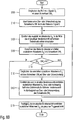
Im ersten Verfahrensschritt S10 der ersten Ausführungsform des erfindungsgemäßen Verfahrens zur digitalen Triggersignal-Erzeugung in
In the first method step S10 of the first embodiment of the inventive method for digital trigger signal generation in
Im darauffolgenden Verfahrensschritt S20 werden mit Hilfe eines Flankendetektors 9 aus dem Vergleichsergebnis des Verfahrensschritts S10 die beiden Abtastwerte Si,j und Si,j-1 des Referenz-Signals Si identifiziert, zwischen denen eine Über- oder Unterschreitung des Schwellwerts SWi durch die beiden Abtastwerte Si,j und Si,j-1 des Referenz-Signals Si erfolgt.In the subsequent method step S20, the two samples S i, j and S i, j-1 of the reference signal S i are identified with the aid of an edge detector 9 from the comparison result of method step S10, between which an exceeding or undershooting of the threshold value SW i the two samples S i, j and S i, j-1 of the reference signal S i takes place.
Mittels Interpolation in einem Polyphasenfilter werden im Verfahrensschritt S30 die zusätzlichen Abtastwerte S i'des Referenz-Signals Si berechnet, die zwischen dem in Verfahrensschritt S20 identifizierten Abtastwerten Si,j und Si,j-1 des Referenz-Signals Si äquidistant verteilt sind. Die Anzahl der hierbei verwendeten zusätzlichen Abtastwerte S i'des Referenz-Signals Si bestimmt die Genauigkeit des im den folgenden Verfahrensschritten ermittelten Triggerzeitpunkts. Hierbei ist ein technisch sinnvoller Kompromiß zwischen der realisierten Genauigkeit in der Bestimmung des Triggerzeitpunkts und des numerischen Rechenaufwands bei der Berechnung der zusätzlichen Abtastwerte S i'des Referenz-Signals Si mittels Interpolation zu treffen.By means of interpolation in a polyphase filter, in method step S30, the additional samples S i 'of the reference signal S i are calculated which distribute equidistantly between the samples S i, j and S i, j-1 of the reference signal S i identified in method step S20 are. The number of additional samples S i 'of the reference signal S i used in this case determines the accuracy of the trigger time point determined in the following method steps. Here, a technically reasonable compromise between the realized accuracy in the determination of the trigger time and the numerical computational effort in the calculation of the additional samples S i 'of the reference signal S i by means of interpolation to make.
Die in Verfahrensschritt S30 ermittelten zusätzlichen Abtastwerte S i'des Referenz-Signals Si zwischen den beiden in Verfahrensschritt S20 identifizierten Abtastwerten Si,j und Si,j-1 des Referenz-Signals Si werden im darauf folgenden Verfahrensschritt S40 in den Komparator 14 auf Über- oder Unterschreitung des Schwellwerts SWi verglichen.The additional sampled values S i 'of the reference signal S i determined in method step S30 between the two sampled values S i, j and S i, j-1 of the reference signal S i identified in method step S20 become the comparator in the subsequent
Aus den Vergleichsergebnissen des Verfahrensschritt S40 wird im abschließenden Verfahrensschritt S50 derjenige zusätzliche Abtastwerte Si,j' des Referenz-Signals Si aus allen zwischen den beiden in Verfahrensschritt S20 identifizierten zusätzlichen Abtastwerte S i' des Referenz-Signals Si mit einer Auswertelogik 15 ermittelt, der den kürzesten Pegelabstand zum Schwellwert SWi aufweist und somit den vergleichsweise exaktesten Triggerzeitpunkt für die Aktivierung des Triggersignals STR darstellt.From the comparison results of method step S40, in the concluding method step S50 that additional samples S i, j 'of the reference signal S i are determined with an
Die zweite Ausführungsform des erfindungsgemäßen Verfahrens zur digitalen Triggersignal-Erzeugung in
Im darauf folgenden Verfahrensschritt S120 wird im ersten Iterationsschritt der zusätzliche Abtastwert Si,j' des Referenz-Signals Si in der Mitte eines zum ersten Iterationsschritt gehörigen Zeitintervalls mittels Interpolation berechnet, wobei die beiden Grenzen des zum ersten Iterationsschritt gehörigen Zeitintervalls die beiden in Verfahrensschritt S110 identifizierten Abtastwerte Si,j' Si,j-1 des Referenz-Signals Si sind, zwischen denen eine Über- oder Unterschreitung des Schwellwerts SWi durch das Referenz-Signal Si erfolgt. In einem weiteren Iterationsschritt j werden die jeweiligen Grenzen des Zeitintervalls durch die links- oder rechtsseitige Grenze des im vorhergehenden Iterationsschritt j-1 betrachteten Zeitintervalls und einem im vorhergehenden Iterationsschritt j-1 ermittelten Abtastwert Si,j-1 des Referenz-Signals Si bestimmt, der in der Zeitintervallmitte des im vorhergehenden Iterationsschritt j-1 betrachteten Zeitintervalls positioniert ist.In the subsequent method step S120, the additional sample value S i, j 'of the reference signal S i is calculated in the middle of a time interval belonging to the first iteration step by means of interpolation in the first iteration step, the two limits of the time interval belonging to the first iteration step the two in method step S110 identified samples S i, j ' S i, j-1 of the reference signal S i are, between which an overshoot or undershooting of the threshold value SW i by the reference signal S i . In a further iteration step j, the respective limits of the time interval are determined by the left or right-hand boundary of the time interval considered in the preceding iteration step j-1 and a sample value S i, j-1 of the reference signal S i determined in the preceding iteration step j-1 which is positioned at the time interval center of the time interval considered in the preceding iteration step j-1.
Der in Verfahrensschritt S120 mittels Interpolation berechnete zusätzliche Abtastwert Si,j' des Referenz-Signals Si, der in der Mitte des im jeweiligen Iterationsschritt j betrachteten Zeitintervalls positioniert ist, wird im darauf folgenden Verfahrensschritt S130 mit dem Pegel des Schwellwerts SWi auf Über- oder -Unterschreitung verglichen.The additional sample S i, j 'of the reference signal S i calculated in step S120 by means of interpolation, which is positioned in the middle of the time interval considered in the respective iteration step j, becomes in the following method step S130 the level of the threshold value SW i - or underrun compared.
Im darauf folgenden Verfahrensschritt S130 wird der Abstand des in Verfahrensschritt S120 ermittelten zusätzlichen Abtastwerts Si,j' des Referenz-Signals Si, der in der Mitte des im jeweiligen Iterationsschritt j betrachteten Zeitintervalls positioniert ist, zum Schwellwert SWi berechnet.In the subsequent method step S130, the distance of the additional sample value S i, j 'of the reference signal S i determined in method step S120, which is positioned in the middle of the time interval considered in the respective iteration step j, is calculated as the threshold value SW i .
Ergibt der Vergleich des Pegelabstands zwischen dem zusätzlichen Abtastwert Si,j' des Referenz-Signals Si und dem Schwellwert SWi mit einem vorgegebenen Grenzwert G in Verfahrensschritt S140 noch keine Unterschreitung des Grenzwerts G durch den Pegelabstand zwischen dem zusätzlichen Abtastwert Si,j' des Referenz-Signals Si und dem Schwellwert SWi, so wird in Verfahrensschritt S150 der zusätzliche Abtastwert Si,j' des Referenz-Signals Si mit dem Schwellwert SWi auf Über- oder -Unterschreitung verglichen.If the comparison of the level difference between the additional sample value S i, j 'of the reference signal S i and the threshold value SW i with a predetermined limit value G in method step S140 does not result in the limit value G being undershot by the level difference between the additional sample value S i, j 'of the reference signal S i and the threshold value SW i , the additional sample value S i, j ' of the reference signal S i is compared with the threshold value SW i for overshoot or undershoot in method step S150.
Auf den Vergleich in Verfahrensschritt S150 aufbauend wird im folgenden Verfahrensschritt S160 das im folgenden Iterationsschritt j+1 zu betrachtende Zeitintervall bestimmt. Die vom in Verfahrensschritt S120 betrachteten zusätzlichen Abtastwert Si,j' des Referenz-Signals Si linksseitig gelegene Hälfte des im Iterationsschritt j betrachteten Zeitintervalls wird im folgenden Iterationsschritt j+1 weiterverfolgt, falls bei einer gewählten positiven Flankentriggerung der zusätzliche Abtastwert Si,j' des Referenz-Signals Si den Schwellwert SWi überschreitet oder bei einer gewählten negativen Flankentriggerung der zusätzliche Abtastwert Si,j' des Referenz-Signals Si den Schwellwert SWi unterschreitet. Die vom in Verfahrensschritt S120 betrachteten zusätzlichen Abtastwert Si,j' des Referenz-Signals Si rechtsseitig gelegene Hälfte des im Iterationsschritt j betrachteten Zeitintervalls wird dagegen im folgenden Iterationsschritt j+1 weiterverfolgt, falls bei einer gewählten positiven Flankentriggerung der zusätzliche Abtastwert Si,j' des Referenz-Signals Si den Schwellwert SWi unterschreitet oder bei einer gewählten negativen Flankentriggerung der zusätzliche Abtastwert Si,j' des Referenz-Signals Si den Schwellwert SWi überschreitet. Anschließend wird in Verfahrensschritt S120 der zusätzliche Abtastwert Si,j+1' des Referenz-Signals Si in der Mitte des im Iterationsschritt j+1 betrachteten Zeitintervalls mittels Interpolation bestimmt.Based on the comparison in method step S150, the time interval to be considered in the following iteration step j + 1 is determined in the following method step S160. The half of the time interval considered in the iteration step j considered by the additional sample S i, j 'of the reference signal S i considered in method step S120 is followed up in the following iteration step j + 1, if the additional sample value S i, j is selected for a selected positive edge triggering 'of the reference signal S i i exceeds the threshold value SW or at a selected negative Edge triggering of the additional sampled S i, j 'of the reference signal S i to the threshold value SW i below. By contrast, the half of the time interval considered in the iteration step j considered by the additional sampling value S i, j 'of the reference signal S i considered in method step S120 is traced further in the following iteration step j + 1 if the additional sampling value S i is selected for a selected positive edge triggering . j 'of the reference signal S i to the threshold value SW i is less than or S i, j at a selected negative edge triggering of the additional sampled' of the reference signal S i exceeds the threshold value SW i. Subsequently, in method step S120, the additional sample value S i, j + 1 'of the reference signal S i in the middle of the time interval considered in the iteration step j + 1 is determined by means of interpolation.
Ergibt dagegen der Vergleich des Pegelabstands zwischen dem zusätzlichen Abtastwert Si,j' des Referenz-Signals Si und dem Schwellwert SWi mit einem vorgegebenen Grenzwert G in Verfahrensschritt S140 eine Unterschreitung des Grenzwerts G durch den Pegelabstand zwischen dem zusätzlichen Abtastwert Si,j' des Referenz-Signals Si und dem Schwellwert SWi, so wird das Iterationsverfahren beendet und in Verfahrensschritt S170 der im aktuellen Iterationsschritt j ermittelte zusätzliche Abtastwert Si,j' des Referenz-Signals Si als gesuchter Triggerzeitpunkt für das Triggersignal STR' festgelegt.On the other hand, the comparison of the level difference between the additional sample value S i, j 'of the reference signal S i and the threshold value SW i with a predetermined limit value G in method step S140 results in the limit value G being undershot by the level difference between the additional sample value S i, j 'of the reference signal S i and the threshold value SW i , the iteration method is ended and in step S170 the additional sample value S i, j ' of the reference signal S i determined in the current iteration step j is selected as the desired trigger time for the trigger signal S TR '. established.
Die dritte Ausführungsform des erfindungsgemäßen Verfahrens zur Triggersignal-Erzeugung in
Im abschließenden Verfahrensschritt S270 werden auf der Basis der in den letzten beiden Iterationsschritten j und j-1 ermittelten zusätzlichen Abtastwerte Si,j' und Si,j-1' des Referenz-Signals Si und ihren zugehörigen Abtastzeitpunkten sowie des Schwellwerts SWi mittels linearer Interpolation der Schnittpunkt zwischen Schwellwert SWi und Referenz-Signals Si als präziserer Triggerzeitpunkt des Triggersignals STR" berechnet.In the concluding method step S270, on the basis of the additional samples S i, j 'and S i, j-1 ' of the reference signal S i and their associated sampling times determined in the last two iteration steps j and j-1 and of the threshold value SW i calculated by means of linear interpolation, the intersection between threshold SW i and reference signal S i as a more precise trigger time of the trigger signal S TR ".
Im folgenden wird die erste, zweite, dritte und vierte Ausführungsform des erfindungsgemäßen Verfahrens zur digitalen Triggerung anhand der
In Verfahrensschritt S300 der ersten Ausführungsform des erfindungsgemäßen Verfahrens zur digitalen Triggerung in
In method step S300 of the first embodiment of the inventive method for digital triggering in
Im folgenden Verfahrensschritt S310 wird das Referenz-Signal Si unter Heranziehung der ersten, zweiten oder dritten Ausführungsform des erfindungsgemäßen Verfahrens zur Triggersignal-Erzeugung gemäß
In Verfahrensschritt S400 der zweiten Ausführungsform des erfindungsgemäßen Verfahrens zur digitalen Triggerung in
Die in Verfahrensschritt S400 jeweils erzeugten Triggersignale STR1, STR2, ..., STRN werden anschließend in Verfahrensschritt S410 in einer Triggersignal-Verknüpfungseinheit 29' zu einem kombinierten Triggersignal STR miteinander verknüpft.The trigger signals S TR1 , S TR2 ,..., S TRN respectively generated in method step S400 are subsequently linked together in method step S410 in a trigger signal combining unit 29 'to form a combined trigger signal S TR .
Die dritte Ausführungsform des erfindungsgemäßen Verfahrens zur digitalen Triggerung in
In Verfahrensschritt S600 der vierten Ausführungsform des erfindungsgemäßen Verfahrens zur digitalen Triggerung in
Die in Verfahrensschritt S600 jeweils erzeugten Triggersignale STR1, STR2, ..., STRN werden im anschließenden Verfahrensschritt S610 in einer Triggersignal-Verknüpfungseinheit 29' zu einem kombinierten Triggersignal STR miteinander verknüpft.The trigger signals S TR1 , S TR2 ,..., S TRN respectively generated in method step S600 are linked to one another in the subsequent method step S610 in a trigger signal combination unit 29 'to form a combined trigger signal S TR .
Ergibt der Vergleich des Referenz-Signals Si mit dem Schwellwert SWi im Komparator 8, 8' oder 8'', dass die Pegel zweier aufeinander folgender Abtastwerte Si,j, Si,j-1 des Referenz-Signals Si unterhalb des Schwellwerts SWi liegen, so kann es u. U. vorkommen, dass aufgrund einer zu niedrigen Abtastrate das Referenz-Signal Si zwischen den beiden aufeinander folgenden Abtastwerten Si,j, Si,j-1 des Referenz-Signals Si den Schwellwert SWi überschreitet, ohne dass eine Triggerung bewirkt wird. Entsprechend kann es auch vorkommen, dass im Falle eines Überschreitens des Schwellwerts SWi durch die beiden aufeinander folgenden Abtastwerte Si,j' Si,j-1 des Referenz-Signals Si das Referenz-Signal Si zwischen den beiden aufeinander folgenden Abtastwerten Si,j' Si,j-1 aufgrund einer zu niedrigen Abtastrate den Schwellwert SWi unterschreitet, ohne dass eine Triggerung bewirkt wird.If the comparison of the reference signal S i with the threshold value SW i in the
Hierzu wird die erste, zweite und dritte Ausführungsform des erfindungsgemäßen Verfahrens zur Triggersignal-Erzeugung in den
Die vierte Ausführungsform des erfindungsgemäßen Verfahrens zur Triggersignal-Erzeugung in
Der darauf folgende zweite Verfahrensschritt S710 der vierten Ausführungsform untersucht im Gegensatz zum zweiten Verfahrensschritt S20 der ersten Ausführungsform, ob zwei aufeinanderfolgende Abtastwerte Si,j und Si,j-1 des Referenz-Signals Si jeweils unterhalb oder oberhalb des Schwellwerts SWi liegen.The following second method step S710 of the fourth embodiment, in contrast to the second method step S20 of the first embodiment, examines whether two consecutive samples S i, j and S i, j-1 of the reference signal S i are respectively below or above the threshold value SW i ,
Liegen die Abtastwerte Si,j und Si,j-1 des Referenz-Signals Si jeweils beide oberhalb oder unterhalb des Schwellwerts SWi, so werden im darauf folgenden Verfahrensschritt S720 mittels Interpolation zusätzliche Abtastwerte S i'' zwischen den beiden in Verfahrensschritt S710 identifizierten Abtastwerte Si,j und Si,j-1 des Referenz-Signals Si berechnet.If the samples S i, j and S i, j-1 of the reference signal S i are both above or below the threshold value SW i , then in the following method step S720 additional samples S i "are interpolated between the two in method step S710 identified samples S i, j and S i, j-1 of the reference signal S i calculated.
Die ermittelten zusätzlichen Abtastwerte S i" werden im folgenden Verfahrensschritt S730 mit dem Schwellwert SWi verglichen.The determined additional samples S i "are compared in the following method step S730 with the threshold value SW i .
Im Verfahrensschritt S740 wird in Abhängigkeit von einer positiven oder negativen Flankentriggerung diejenigen zusätzlichen Abtastwerte Si,j'' und Si,j-1" des Referenz-Signals Si identifiziert, zwischen denen der Schwellwert SWi liegt, und bei einer Identifizierung schließlich derjenige zusätzliche Abtastwert Si,j'' oder Si,j-1" ' des Referenz-Signals Si, der den kürzesten Abstand zum Schwellwert SWi aufweist, als gesuchter Triggerzeitpunkt für das Triggersignal STR'" ermittelt.In method step S740, depending on a positive or negative edge triggering, those additional samples S i, j "and S i, j-1 " of the reference signal S i are identified, between which the threshold value SW i lies, and finally upon identification that additional sample value S i, j "or S i, j-1 "'of the reference signal S i , which has the shortest distance to the threshold value SW i , determined as the desired trigger time for the trigger signal S TR '".
Wird gemäß Verfahrensschritt S750 ein Triggerereignis identifiziert, so wird in Verfahrensschritt S760 ein Triggersignal STR'" erzeugt, das mit dem identifizierten Triggerzeitpunkt aktiviert ist.If, according to method step S750, a trigger event is identified, then in method step S760 a trigger signal S TR '"is generated, which is activated with the identified trigger time.
Die fünfte Ausführungsform des erfindungsgemäßen Verfahrens zur Triggersignal-Erzeugung in
In Verfahrensschritt S810 der fünften Ausführungsform werden in Abgrenzung zu Verfahrensschritt S110 der zweiten Ausführungsform zwei aufeinander folgende Abtastwerte Si,j und Si,j-1 des Referenz-Signals Si identifiziert, die beide entweder unterhalb oder oberhalb des Schwellwerts SWi liegen.In method step S810 of the fifth embodiment, in contrast to method step S110 of the second embodiment, two consecutive samples S i, j and S i, j-1 of the reference signal S i are identified, which are either either below or above the threshold value SW i .
Im darauf folgenden Verfahrensschritt S820 wird im Rahmen einer Iteration ein zusätzlicher Abtastwert Si,j" des Referenz-Signals Si mittels Interpolation berechnet, der sich in der Mitte des im jeweiligen Iterationsschritt betrachteten Zeitintervalls befindet. Im ersten Iterationsschritt wird das Zeitintervall zwischen den aufeinander folgenden Abtastwerten Si,j und Si,j-1 des Referenz-Signals Si betrachtet.In the subsequent method step S820, an additional sample S i, j "of the Reference signal S i calculated by means of interpolation, which is located in the middle of the time interval considered in the respective iteration step. In the first iteration step, the time interval between the consecutive samples S i, j and S i, j-1 of the reference signal S i is considered.
Im nächsten Verfahrensschritt S830 wird geprüft, ob die aufeinander folgende Abtastwerte Si,j und Si,j-1 sowie der im aktuellen Iterationsschritt ermittelte zusätzliche Abtastwert Si,j'' des Referenz-Signals Si alle oberhalb oder alle unterhalb des Schwellwerts SWi liegen.In the next method step S830, it is checked whether the consecutive samples S i, j and S i, j-1 and the additional sample S i, j "of the reference signal S i determined in the current iteration step are all above or all below the threshold value SW i lie.
Ist dies der Fall, so muß in einem weiteren Iterationsschritt ein zusätzlicher Abtastwert Si,j'' des Referenz-Signals Si innerhalb eines Zeitintervalls ermittelt werden, das sich innerhalb des Zeitintervalls des aktuellen Iterationsschritt befindet und zu diesem halbiert ist. Hierzu wird in Verfahrensschritt S840 dasjenige halbierte Zeitintervall, das zum im aktuellen Iterationsschritt ermittelten zusätzlichen Abtastwert Si,j'' des Referenz-Signals Si entweder links- oder rechtsseitig gelegen ist, ausgewählt, das zwischen demjenigen Abtastwert Si,j und Si,j-1 und dem im aktuellen Iterationsschritt ermittelten zusätzlichen Abtastwert Si,j'' des Referenz-Signals Si liegt, der den kürzeren Pegelabstand zum Schwellwert SWi aufweist. Im allgemeinen ist innerhalb von ein bis zwei Iterationszyklen ein Über- oder Unterschreiten des Schwellwerts SWi durch das Referenz-Signal Si eindeutig identifiziert oder eindeutig nicht identifiziert (wegen Frequenzbegrenzung des Referenz-Signals Si aufgrund des Abtasttheorems).If this is the case, then in a further iteration step, an additional sample value S i, j "of the reference signal S i must be determined within a time interval that is within the time interval of the current iteration step and halved relative thereto. For this purpose, in method step S840, that halved time interval which is located either at the left or at the right-hand side relative to the additional sample value S i, j "of the reference signal S i determined in the current iteration step is selected, which is between the sample value S i, j and S i , j-1 and the additional sample S i, j "of the reference signal S i determined in the current iteration step, which has the shorter level distance from the threshold value SW i . In general, within one to two iteration cycles, an exceeding or falling below the threshold value SW i by the reference signal S i uniquely identified or unambiguously unidentified (due to frequency limitation of the reference signal S i due to the sampling theorem).
Wird in Verfahrensschritt S830 ein Über- oder Unterschreiten des Schwellwerts SWi durch das Referenz-Signal Si registriert, so wird in Verfahrensschritt S850 durch die iterative Berechnung von zusätzlichen Abtastwerten S i" innerhalb des im letzten Iterationsschritt betrachteten Zeitintervalls ein präziserer Schnittpunkt zwischen Schwellwert SWi und Referenz-Signal Si ermittelt. Verfahrensschritt S850 beinhaltet im wesentlichen die Verfahrensschritte S120 bis S160 der zweiten Ausführungsform des erfindungsgemäßen Verfahrens zur Triggersignal-Erzeugung in
Schließlich wird im abschließenden Verfahrensschritt S860 auf der Basis des in Verfahrensschritt S850 ermittelten Triggerzeitpunkt ein Triggersignal STR"" generiert.Finally, in the concluding method step S860, a trigger signal S TR "" is generated on the basis of the trigger time determined in method step S850.
In
In
In Verfahrensschritt S960 der sechsten Ausführungsform wird in Analogie zu Verfahrensschritt S270 der dritten Ausführungsform mittels linearer Interpolation zwischen den im letzten Iterationsschritt des Verfahrensschrittes S950 betrachteten Zeitintervalls mit seinen Zeitintervallsgrenzen - den in den letzten beiden Iterationsschritten ermittelten zusätzlichen Abtastwerten Si,j'' und Si,j+1'' des Referenz-Signals Si - ein präziserer Triggerzeitpunkt als Schnittpunkt zwischen Schwellwert SWi und Referenz-Signal Si berechnet.In method step S960 of the sixth embodiment, in analogy to method step S270 of the third embodiment, by means of linear interpolation between the time interval considered in the last iteration step of method step S950 with its time interval limits-the additional samples S i, j "and S i determined in the last two iteration steps , j + 1 '' of the reference signal S i - calculates a more precise trigger time as an intersection between the threshold value SW i and the reference signal S i .
Schließlich wird im abschließenden Verfahrensschritt S970 auf der Basis des in Verfahrensschritt S960 ermittelten Triggerzeitpunkts ein Triggersignal STR"'" erzeugt.Finally, in the concluding method step S970, a trigger signal S TR "'" is generated on the basis of the trigger time point determined in method step S960.
Die Erfindung ist nicht auf die dargestellten Ausführungsformen beschränkt. Insbesondere sind neben Interpolationsverfahren mit Polyphasenfilter auch andere Interpolationsverfahren von der Erfindung abgedeckt.The invention is not limited to the illustrated embodiments. In particular, besides interpolation methods with polyphase filters, other interpolation methods are also covered by the invention.
Claims (23)
dadurch gekennzeichnet,
dass zwischen zwei aufeinander folgenden Abtastwerten (Si,j' Si,j-1) des Referenz-Signals (Si) mindestens ein zusätzlicher Abtastwert (Si,j', Si,j") des Referenz-Signals (Si) mittels Interpolation ermittelt wird und
dass das Referenz-Signal (Si) aus einem oder mehreren der auf dem Oszilloskop darzustellenden Signale (S) mittels Signalverknüpfung ermittelt wird.Method for the digital triggering of a recording of one or more signals (S) on a digital oscilloscope, by determining in each case between two consecutive samples (S i, j ' S i, j-1 ) of a reference signal (S i ) for determining a trigger instant and a threshold value (SW i ) a level comparison is performed,
characterized,
that between two consecutive sample values (S i, j 'S i, j-1) of the reference signal (S i) at least one additional sample value (S i, j', S i, j ") of the reference signal (S i ) is determined by means of interpolation and
that the reference signal (S i) of one or more of the displayed on the oscilloscope signals (S) is determined by means of signal link.
dadurch gekennzeichnet,
dass der Triggerzeitpunkt zwischen zwei aufeinander folgenden Abtastwerten (Si,j bzw. Si,j', Si,j-1 bzw. Si,j-1') des Referenz-Signals (Si) liegt, falls eine Über- oder Unterschreitung des Schwellwerts (SWi) durch das Referenz-Signal (Si) zwischen den beiden aufeinander folgenden Abtastwerten (Si,j bzw. Si,j', Si,j-1 bzw. Si,j-1') des Referenz-Signals (Si) vorliegt.Method for digital triggering according to claim 1,
characterized,
that the trigger time is between two consecutive samples (S i, j or S i, j ', S i, j-1 and S i, j-1 ') of the reference signal (S i ), if an over or undershooting of the threshold value (SW i ) by the reference signal (S i ) between the two successive sampling values (S i, j or S i, j ', S i, j-1 and S i, j- 1 ') of the reference signal (S i ) is present.
dadurch gekennzeichnet,
dass eine Überschreitung des Schwellwerts (SWi) durch das Referenz-Signal (Si) zwischen den beiden aufeinander folgenden Abtastwerten (Si,j bzw. Si,j', Si,j-1 bzw. Si,j-1') des Referenz-Signals (Si) vorliegt, falls der eine Abtastwert (Si,j bzw. Si,j') kleiner als der Schwellwert (SWi) und der andere Abtastwert (Si,j-1 bzw. Si,j-1') größer oder gleich dem Schwellwert (SWi) ist.Method for digital triggering according to claim 2,
characterized,
in that the threshold value (SW i ) is exceeded by the reference signal (S i ) between the two successive sampling values (S i, j or S i, j ', S i, j-1 and S i, j-). 1 ') of the reference signal (S i ) is present, if the one sample (S i, j or S i, j ') is smaller than the threshold value (SW i ) and the other sample value (S i, j-1 or S i, j-1 ') is greater than or equal to the threshold value (SW i ).
dadurch gekennzeichnet,
dass eine Unterschreitung des Schwellwerts (SWi) durch das Referenz-Signal (Si) zwischen den beiden aufeinander folgenden Abtastwerten (Si,j bzw. Si,j', Si,j-1 bzw. Si,j-1') des Referenz-Signals (Si) vorliegt, falls der eine Abtastwert (Si,j bzw. Si,j') größer als der Schwellwert (SWi) und der andere Abtastwert (Si,j-1 bzw. Si,j-1') kleiner oder gleich dem Schwellwert (SWi) ist.Method for digital triggering according to claim 2,
characterized,
that an undershoot of the threshold value (SW i) by the reference signal (S i) between the two successive samples (S i, j and S i, j ', S i, j-1 and S i, j 1 ') of the reference signal (S i ) is present, if the one sample (S i, j or S i, j ') is greater than the threshold value (SW i ) and the other sample value (S i, j-1 or S i, j-1 ') is less than or equal to the threshold value (SW i ).
dadurch gekennzeichnet,
dass der Triggerzeitpunkt zwischen zwei aufeinander folgenden Abtastwerten (Si,j bzw. Si,j', Si,j-1 bzw. Si,j-1') des Referenz-Signals (Si) mittels linearer Interpolation berechnet wird.Method for digital triggering according to claim 2,
characterized,
that the trigger time between two consecutive sample values (S i, j and S i, j 'S, j-1 and S i, j-1 i,') of the reference signal (S i) is calculated by linear interpolation ,
dadurch gekennzeichnet,
dass die zusätzlichen Abtastwerte (Si,j') des Referenz-Signals (Si) äquidistant zwischen zwei aufeinander folgenden Abtastwerten (Si,j, Si,j-1) des Referenz-Signals (Si) verteilt sind.Method for digital triggering according to one of claims 1 to 5,
characterized,
in that the additional sampled values (S i, j ') of the reference signal (S i ) are distributed equidistantly between two successive sampled values (S i, j , S i, j-1 ) of the reference signal (S i ).
dadurch gekennzeichnet,
dass die zusätzlichen Abtastwerte (Si,j') des Referenz-Signals (Si) iterativ jeweils in der Mitte eines gegenüber einem im vorherigen Iterationsschritt (j-1) betrachteten Zeitintervalls halbierten Zeitintervalls mittels Interpolation ermittelt werden.Method for digital triggering according to one of claims 1 to 5,
characterized,
that the additional sample values (S i, j ') of the reference signal (S i) iteratively halved in each case in the middle of a previous iteration step in respect to a (j-1) observed time interval time interval are determined by means of interpolation.
dadurch gekennzeichnet,
dass das im Iterationsschritt (j) betrachtete Zeitintervall das zum im Iterationsschritt (j-1) ermittelten zusätzlichen Abtastwert (Si,j') des Referenz-Signals (Si) linksseitig gelegene Zeitintervall ist, falls der Schwellwert (SWi) zwischen dem im Iterationsschritt (j-1) ermittelten zusätzlichen Abtastwert (Si,j') des Referenz-Signals (Si) und dem linksseitig benachbarten Abtastwert des Referenz-Signals (Si) liegt.Method for digital triggering according to claim 7,
characterized,
that the time interval in the iteration step (j) considered (i, j 'S) of the reference signal (S i) to the left side location, time interval, the determined for the iteration (j-1) additional sampled, if the threshold value (SW i) between the in the iteration step (j-1) determined additional sample (S i, j ') of the reference signal (S i ) and the left side adjacent sample of the reference signal (S i ).
dadurch gekennzeichnet,
dass das im Iterationsschritt (j) betrachtete Zeitintervall das zum im Iterationsschritt (j-1) ermittelten zusätzlichen Abtastwert (Si,j') des Referenz-Signals (Si) rechtsseitig gelegene Zeitintervall ist, falls der Schwellwert (SWi) zwischen dem im Iterationsschritt (j-1) ermittelten zusätzlichen Abtastwert (Si,j') des Referenz-Signals (Si) und dem rechtsseitig benachbarten Abtastwert des Referenz-Signals (Si) liegt.Method for digital triggering according to claim 7,
characterized,
in that the time interval considered in the iteration step (j) is the time interval located on the right-hand side for the additional sampling value (S i, j ') of the reference signal (S i ) determined in the iteration step (j-1) if the threshold value (SW i ) lies between the in the iteration step (j-1) determined additional sample (S i, j ') of the reference signal (S i ) and the right side adjacent sample of the reference signal (S i ).
dadurch gekennzeichnet,
dass zur Identifizierung eines Triggerpunktes zwischen zwei aufeinander folgenden Abtastwerten (Si,j bzw. Si,j', Si,j-1 bzw. Si,j-1') des Referenz-Signals (Si) im Fall von fehlender Über- oder Unterschreitung des Schwellwerts (SWi) durch das Referenz-Signal (Si) zwischen den beiden aufeinander folgenden Abtastwerten (Si,j' Si,j-1) des Referenz-Signals (Si) zusätzliche Abtastwerte (Si,j'') des Referenz-Signals (Si) mittels Interpolation ermittelt werden.Method for digital triggering according to claim 2,
characterized,
that for identifying a trigger point between two consecutive samples (S i, j or S i, j ', S i, j-1 and S i, j-1 ') of the reference signal (S i ) in the case of missing overshoot or undershoot of the threshold value (SW i ) by the reference signal (S i ) between the two successive sampling values (S i, j ' S i, j-1 ) of the reference signal (S i ) S i, j '') of the reference signal (S i ) are determined by means of interpolation.
dadurch gekennzeichnet,
dass der zusätzliche Abtastwert (Si,j'') des Referenz-Signals (Si) und der jeweils links- oder rechtsseitig benachbarte Abtastwert (Si,j, Si,j-1) des Referenz-Signals (Si) jeweils mit dem Schwellwert (SWi) zur Identifizierung einer Über- oder Unterschreitung des Schwellwerts (SWi) durch das Referenz-Signal (Si) zwischen dem zusätzliche Abtastwert (Si,j'') des Referenz-Signals (Si) und dem jeweils links- oder rechtsseitig benachbarten Abtastwert (Si,j' Si,j-1) des Referenz-Signals (Si) verglichen wird.Method for digital triggering according to claim 10,
characterized,
that the additional sample (S i, j '') of the reference signal (S i ) and the left or right side adjacent sample value (S i, j , S i, j-1 ) of the reference signal (S i ) in each case with the threshold value (SW i ) for identifying an overshoot or undershooting of the threshold value (SW i ) by the reference signal ( S i) 'i) of the reference signal (S i) and (the respective left or right side adjacent sample S, j' (i, j 'between the additional sample value (S S i, j-1) of the reference signal S i ) is compared.
dadurch gekennzeichnet,
dass die zusätzlichen Abtastwerte (Si,j'') des Referenz-Signals (Si) mittels Interpolation ermittelt werden und äquidistant zwischen den beiden aufeinander folgenden Abtastwerten (Si,j, Si,j-1) des Referenz-Signals (Si) verteilt sind.Method for digital triggering according to claim 10 or 11,
characterized,
that the additional sample values (S i, j '') of the reference signal (S i) are determined by interpolation and equidistant between the two successive samples (S i, j, S i, j-1) of the reference signal ( S i ) are distributed.
dadurch gekennzeichnet,
dass die zusätzlichen Abtastwerte (Si,j'') des Referenz-Signals (Si) iterativ mittels linearer Interpolation in der Nähe desjenigen Abtastwertes (Si,j, Si,j-1) des Referenz-Signals (Si) ermittelt werden, der einen kürzeren Pegelabstand zum Pegel des Schwellwerts (SWi) aufweist.Method for digital triggering according to claim 10 or 11,
characterized,
in that the additional samples (S i, j '') of the reference signal (S i ) iteratively by means of linear interpolation in the vicinity of that sample value (S i, j , S i, j-1 ) of the reference signal (S i ) are determined, which has a shorter level distance to the level of the threshold value (SW i ).
dadurch gekennzeichnet,
dass die Berechnung des Triggerzeitpunkts online während der Messung der Signale (S) oder offline nach Abschluß der Messung der Signale (S) erfolgt.Method for digital triggering according to one of claims 1 to 13,
characterized,
that the calculation of the triggering time takes place online during the measurement of the signals (S) or offline after the completion of the measurement of the signals (S).
dadurch gekennzeichnet,
dass das Referenzsignal (Si) mit einem oberen Schwellwertpegel hinsichtlich Überschreitung und mit einem unteren Schwellwertpegel hinsichtlich Unterschreitung verglichen wird.Method for digital triggering according to one of Claims 1 to 14,
characterized,
that the reference signal (S i) is compared with an upper threshold level is exceeded with respect to a lower threshold level and with regard to underflow.
dadurch gekennzeichnet,
dass die beiden Teilsignale eines differentiellen Signals jeweils gegen Massepotential gemessen werden und mittels differentieller Signalverknüpfung zu einem differentiellen Signal zusammengeführt werden, das das Referenz-Signal (Si) bildet.Method for digital triggering according to one of claims 1 to 15,
characterized,
that the two partial signals of a differential signal are respectively measured against ground potential and are brought together by means of differential signal combination to form a differential signal which forms the reference signal (S i ).
dadurch gekennzeichnet,
dass vor Ermittlung des Referenz-Signals (Si) aus einzelnen auf dem Oszilloskop darzustellenden Signalen (S) Übertragungszeit-Unterschiede in den zu den darzustellenden Signalen (S) jeweils gehörigen Messkanälen, durch Bestimmung der Übertragungszeit-Unterschiede zwischen den einzelnen darzustellenden Signalen (S) und durch Kompensation der Übertragungszeitunterschiede bei den einzelnen darzustellenden Signalen beseitigt werden.Method for digital triggering according to one of Claims 1 to 16,
characterized,
that before determining the reference signal (S i ) from individual signals (S) to be displayed on the oscilloscope, transmission time differences in the respective measurement channels associated with the signals (S) to be represented are determined by determining the transmission time differences between the individual signals ( S ) and by compensating the transmission time differences in the individual signals to be displayed.
dadurch gekennzeichnet,
dass die Einheit (13, 13', 13", 13"', 13"", 13""') zur Bestimmung des Triggerzeitpunkts zusätzliche Abtastwerte (Si,j', Si,j'') des Referenz-Signals (Si) zwischen zwei aufeinander folgenden Abtastwerten (Si,j' Si,j-1) des Referenz-Signals (Si) mittels Interpolation ermittelt und
dass jedem Komparator (8, 8", 8", 8"', 8"", 8""') eine Triggerverknüpfungslogik (29) zur Bildung des Referenz-Signals (Si) aus einem oder mehreren der auf dem Oszilloskop darzustellenden Signale (S) vorgeschaltet ist.System for the digital triggering of a recording of one or more signals ( S ) for a digital oscilloscope with at least one comparator (8, 8 ', 8'',8''', 8 "", 8 ""') in which between each two successive samples (S i, j ' S i, j-1 ) of a reference signal (S i ) and a threshold value (SW i ), a level comparison is performed, and one of the comparator (8, 8', 8 ", 8 "', 8"",8""') following unit (13, 13 ', 13'',13''',13"",13""') for determining the triggering time,
characterized,
in that the unit (13, 13 ', 13 ", 13"', 13 "", 13 ""') for determining the triggering time has additional sampled values (S i, j ', S i, j ") of the reference signal ( S i ) between two consecutive samples (S i, j ' S i, j-1 ) of the reference signal (S i ) is determined by means of interpolation and
in that each comparator (8, 8 ", 8", 8 "', 8"",8""') has trigger logic (29) for forming the reference signal (S i ) from one or more of the signals to be displayed on the oscilloscope (S) is connected upstream.
dadurch gekennzeichnet,
dass jeder Komparator (8, 8', 8", 8"', 8"", 8""') eine Hysterese mit einem oberen und unteren Schwellwert aufweist, wobei der obere Schwellwert im Fall einer Überschreitung des Referenz-Signals (Si) und der untere Schwellwert im Fall einer Unterschreitung des Referenz-Signals (Si) herangezogen wird.A digital triggering system according to claim 18,
characterized,
that each comparator (8, 8 ', 8 ", 8"', 8 "", 8 ""') has a hysteresis with an upper and lower threshold, the upper threshold value (in the case of exceeding the reference signal S i ) and the lower threshold in the case of a fall below the reference signal (S i ) is used.
dadurch gekennzeichnet,
dass der obere und untere Schwellwert jeweils einstellbar ist.A digital triggering system according to claim 19,
characterized,
that the upper and lower threshold value is adjustable in each case.
dadurch gekennzeichnet,
dass das digitale Triggersystem (5, 5', 5'', 5''') einen auftretenden Triggerzeitpunkt mit absoluter Sicherheit ermittelt, der gegenüber der Abtastrate des Analog-Digital-Wandlers (2) eine höhere zeitliche Auflösung aufweist und
dass das digitale Triggersystem (5, 5', 5'', 5''') gemäß einem oder mehreren der Ansprüche 18 bis 20 ausgeführt ist.Digital oscilloscope comprising a preamplifier (1) for level adjustment of at least one signal ( S ) to be displayed on the digital oscilloscope, an analog-digital converter (2) for analog-digital conversion of the signals ( S ) to be represented, a digital trigger system (5, 5 ', 5'',5''') for determining a trigger time and a recording unit (6) for displaying the signals ( S ) to be displayed,
characterized,
that the digital trigger system (5, 5 ', 5'',5''') an occurring trigger time with absolute certainty determined, which compared to the sampling rate of the analog-to-digital converter (2) has a higher temporal resolution, and
in that the digital trigger system (5, 5 ', 5 ", 5"') is designed according to one or more of claims 18 to 20.
dadurch gekennzeichnet,
dass dem digitalen Triggersystem (5, 5', 5'', 5''') und der Aufzeichnungseinheit (6) eine Einheit (3) zur Kompensation von Übertragungszeit-Unterschieden in den zu den darzustellenden Signalen (S) gehörigen Messkanälen vorgeschaltet ist.Digital oscilloscope according to claim 21,
characterized,
in that the digital trigger system (5, 5 ', 5'',5''') and the recording unit (6) are preceded by a unit (3) for compensating transmission time differences in the measurement channels belonging to the signals (S) to be represented.
dadurch gekennzeichnet,
dass dem Analog-Digital-Wandler (2) ein Entzerrungssystem (4) zur Kompensation linearer und nichtlinearer Verzerrungen in jedem der darzustellenden Signale (S) nachgeschaltet ist.Digital oscilloscope according to claim 21 or 22,
characterized,
in that a rectification system (4) for compensating linear and nonlinear distortions in each of the signals (S) to be represented is connected downstream of the analog-to-digital converter (2).
Applications Claiming Priority (3)
| Application Number | Priority Date | Filing Date | Title |
|---|---|---|---|
| DE102005035473A DE102005035473A1 (en) | 2005-07-28 | 2005-07-28 | Method and system for digital triggering for oscilloscopes |
| EP06724534.0A EP1907869B1 (en) | 2005-07-28 | 2006-04-24 | Method and system for digital triggering for oscilloscopes |
| PCT/EP2006/003756 WO2007012355A1 (en) | 2005-07-28 | 2006-04-24 | Method and system for digital triggering for oscilloscopes |
Related Parent Applications (1)
| Application Number | Title | Priority Date | Filing Date |
|---|---|---|---|
| EP06724534.0A Division EP1907869B1 (en) | 2005-07-28 | 2006-04-24 | Method and system for digital triggering for oscilloscopes |
Publications (2)
| Publication Number | Publication Date |
|---|---|
| EP3407073A1 true EP3407073A1 (en) | 2018-11-28 |
| EP3407073B1 EP3407073B1 (en) | 2024-02-14 |
Family
ID=36608729
Family Applications (3)
| Application Number | Title | Priority Date | Filing Date |
|---|---|---|---|
| EP18183830.1A Active EP3407073B1 (en) | 2005-07-28 | 2006-04-24 | Method and system for digital triggering for oscilloscopes |
| EP18183827.7A Active EP3422022B1 (en) | 2005-07-28 | 2006-04-24 | Digital oscilloscope with digital triggering |
| EP06724534.0A Active EP1907869B1 (en) | 2005-07-28 | 2006-04-24 | Method and system for digital triggering for oscilloscopes |
Family Applications After (2)
| Application Number | Title | Priority Date | Filing Date |
|---|---|---|---|
| EP18183827.7A Active EP3422022B1 (en) | 2005-07-28 | 2006-04-24 | Digital oscilloscope with digital triggering |
| EP06724534.0A Active EP1907869B1 (en) | 2005-07-28 | 2006-04-24 | Method and system for digital triggering for oscilloscopes |
Country Status (5)
| Country | Link |
|---|---|
| US (1) | US7860674B2 (en) |
| EP (3) | EP3407073B1 (en) |
| JP (2) | JP5607301B2 (en) |
| DE (1) | DE102005035473A1 (en) |
| WO (1) | WO2007012355A1 (en) |
Families Citing this family (18)
| Publication number | Priority date | Publication date | Assignee | Title |
|---|---|---|---|---|
| US20070200550A1 (en) * | 2006-02-28 | 2007-08-30 | Corredoura Paul L | Trigger architecture, measurement system and method of use |
| US7352167B2 (en) * | 2006-03-24 | 2008-04-01 | Tektronix, Inc. | Digital trigger |
| US20090222797A1 (en) * | 2008-02-29 | 2009-09-03 | Infineon Technologies Ag | Apparatus and method for providing a trigger |
| JP5308133B2 (en) * | 2008-11-27 | 2013-10-09 | インターナショナル・ビジネス・マシーンズ・コーポレーション | Measurement data transfer control device and method |
| DE102009019039A1 (en) * | 2009-04-27 | 2010-11-11 | Rohde & Schwarz Gmbh & Co. Kg | Measuring device and measuring method for measuring differential signals |
| DE102010046098A1 (en) * | 2010-06-23 | 2011-12-29 | Rohde & Schwarz Gmbh & Co. Kg | Measuring device with a trigger unit |
| DE102011078863B4 (en) | 2011-07-08 | 2018-08-02 | Rohde & Schwarz Gmbh & Co. Kg | Apparatus and method for determining absolute level values of a digital signal for a digital oscilloscope |
| EP2651034B1 (en) * | 2012-04-12 | 2014-08-06 | Siemens Aktiengesellschaft | Method for determining a trigger level |
| US8866659B2 (en) | 2012-08-07 | 2014-10-21 | Guzik Technical Enterprises | Data acquisition device with real time digital trigger |
| US9874863B2 (en) | 2015-08-24 | 2018-01-23 | Keysight Technologies, Inc. | Finite state machine-based trigger event detection employing interpolation |
| US10014978B2 (en) | 2015-08-31 | 2018-07-03 | Rohde & Schwarz Gmbh & Co. Kg | Method and apparatus for processing a data signal |
| JP6545221B2 (en) * | 2017-05-15 | 2019-07-17 | アンリツ株式会社 | Spectrum analyzer and signal analysis method |
| CN108427039A (en) * | 2018-05-07 | 2018-08-21 | 哈尔滨工程大学 | Pulse-amplitude modulation signal pulse width measurement method based on ratio thresholding |
| CN108776249B (en) * | 2018-06-26 | 2020-04-14 | 电子科技大学 | Oscillograph recorder with double capturing functions |
| CN109142835B (en) * | 2018-06-26 | 2020-04-14 | 电子科技大学 | Data acquisition system with waveform multi-frame recording function |
| CN109765412B (en) * | 2018-12-28 | 2021-06-01 | 中电科思仪科技股份有限公司 | Method for accurately positioning trigger position based on programmable circuit |
| US11249114B2 (en) | 2019-07-16 | 2022-02-15 | Rohde & Schwarz Gmbh & Co. Kg | Trigger method and measurement device comprising a corresponding trigger method |
| US10924130B1 (en) | 2019-10-10 | 2021-02-16 | Guzik Technical Enterprises | High resolution digital trigger detector |
Citations (5)
| Publication number | Priority date | Publication date | Assignee | Title |
|---|---|---|---|---|
| EP0554973A2 (en) * | 1992-01-31 | 1993-08-11 | Tektronix, Inc. | Multi-channel trigger dejitter |
| US5854996A (en) * | 1993-10-12 | 1998-12-29 | Tektronix, Inc. | Logic signal extraction |
| US6263290B1 (en) * | 1995-02-22 | 2001-07-17 | Michael K. Williams | Process and machine for signal waveform analysis |
| US6598004B1 (en) * | 2000-08-28 | 2003-07-22 | Advantest Corporation | Jitter measurement apparatus and its method |
| US6753677B1 (en) * | 2003-02-28 | 2004-06-22 | Agilent Technologies, Inc. | Trigger jitter reduction for an internally triggered real time digital oscilloscope |
Family Cites Families (8)
| Publication number | Priority date | Publication date | Assignee | Title |
|---|---|---|---|---|
| US4585975A (en) | 1983-04-21 | 1986-04-29 | Tektronix, Inc. | High speed Boolean logic trigger oscilloscope vertical amplifier with edge sensitivity and nested trigger |
| US4678345A (en) * | 1986-05-01 | 1987-07-07 | Tektronix, Inc. | Equivalent time pseudorandom sampling system |
| NL8700267A (en) * | 1987-02-04 | 1988-09-01 | Philips Nv | TRACTOR DEVICE. |
| GB2224869A (en) | 1988-11-07 | 1990-05-16 | Nicolet Instrument Corp | Digital comparator trigger signal |
| US5245630A (en) * | 1991-04-09 | 1993-09-14 | Tektronix, Inc. | Equalized eye pattern instrument |
| EP0740161A3 (en) | 1995-04-27 | 1998-07-29 | Fluke Corporation | Digital oscilloscope with trigger qualification based on pattern recognition |
| US7219025B2 (en) * | 2001-12-18 | 2007-05-15 | Yokogawa Electric Corporation | Waveform measuring instrument using interpolated data |
| US7227349B2 (en) * | 2002-02-11 | 2007-06-05 | Tektronix, Inc. | Method and apparatus for the digital and analog triggering of a signal analysis device |
-
2005
- 2005-07-28 DE DE102005035473A patent/DE102005035473A1/en not_active Withdrawn
-
2006
- 2006-04-24 US US11/997,061 patent/US7860674B2/en active Active
- 2006-04-24 EP EP18183830.1A patent/EP3407073B1/en active Active
- 2006-04-24 WO PCT/EP2006/003756 patent/WO2007012355A1/en active Application Filing
- 2006-04-24 EP EP18183827.7A patent/EP3422022B1/en active Active
- 2006-04-24 EP EP06724534.0A patent/EP1907869B1/en active Active
- 2006-04-24 JP JP2008523139A patent/JP5607301B2/en active Active
-
2012
- 2012-01-04 JP JP2012000260A patent/JP5562982B2/en active Active
Patent Citations (5)
| Publication number | Priority date | Publication date | Assignee | Title |
|---|---|---|---|---|
| EP0554973A2 (en) * | 1992-01-31 | 1993-08-11 | Tektronix, Inc. | Multi-channel trigger dejitter |
| US5854996A (en) * | 1993-10-12 | 1998-12-29 | Tektronix, Inc. | Logic signal extraction |
| US6263290B1 (en) * | 1995-02-22 | 2001-07-17 | Michael K. Williams | Process and machine for signal waveform analysis |
| US6598004B1 (en) * | 2000-08-28 | 2003-07-22 | Advantest Corporation | Jitter measurement apparatus and its method |
| US6753677B1 (en) * | 2003-02-28 | 2004-06-22 | Agilent Technologies, Inc. | Trigger jitter reduction for an internally triggered real time digital oscilloscope |
Non-Patent Citations (2)
| Title |
|---|
| "Bisection method", 26 July 2004 (2004-07-26), EN.WIKIPEDIA.ORG, XP002389052, Retrieved from the Internet <URL:http://web.archive.org/web/20040726154027/http://en.wikipedia.org/wiki/Bisection_method> [retrieved on 20060705] * |
| HANCOCK J: "ZEITINTERVALL-MESSGENAUIGKEIT VON DIGITAL-OSZILLOSKOPEN", ELEKTRONIK, WEKA FACHZEITSCHRIFTENVERLAG, POING, DE, vol. 37, no. 1, 8 January 1988 (1988-01-08), pages 94 - 97, XP000955160, ISSN: 0013-5658 * |
Also Published As
| Publication number | Publication date |
|---|---|
| US20080297139A1 (en) | 2008-12-04 |
| WO2007012355A1 (en) | 2007-02-01 |
| EP3422022B1 (en) | 2024-02-14 |
| JP2012063371A (en) | 2012-03-29 |
| DE102005035473A1 (en) | 2007-02-01 |
| JP2009503456A (en) | 2009-01-29 |
| JP5607301B2 (en) | 2014-10-15 |
| EP1907869A1 (en) | 2008-04-09 |
| JP5562982B2 (en) | 2014-07-30 |
| EP3407073B1 (en) | 2024-02-14 |
| EP3422022A1 (en) | 2019-01-02 |
| US7860674B2 (en) | 2010-12-28 |
| EP1907869B1 (en) | 2018-07-18 |
Similar Documents
| Publication | Publication Date | Title |
|---|---|---|
| EP1907869B1 (en) | Method and system for digital triggering for oscilloscopes | |
| DE69922592T2 (en) | Method for the effective value measurement of signals with a wide dynamic range | |
| DE3210571C2 (en) | ||
| WO2020188054A1 (en) | Apparatus for analysing currents in an electrical load, and load having such an apparatus | |
| DE2706928A1 (en) | ANALOG-DIGITAL CONVERSION METHOD AND SYSTEM | |
| DE69517075T2 (en) | Device for the diagnosis of sound and vibration sources | |
| DE3836280C1 (en) | ||
| DE69132147T2 (en) | Signal control device | |
| DE69322530T2 (en) | Jitter correction for multi-channel trigger arrangement | |
| DE69011566T2 (en) | Acoustic detection device. | |
| DE102004036692B4 (en) | Acceleration detecting device and occupant protection system using the same | |
| DE19728676A1 (en) | Signal processor for gas chromatograph and mass spectrometer | |
| EP0866563A2 (en) | Method and arrangement for the analogue-to-digital conversion of an image signal | |
| EP2359152B1 (en) | Display of spectra | |
| DE102009030318B4 (en) | Apparatus and method for determining a sample rate difference | |
| EP0444234B1 (en) | Method and device for analogue/digital conversion | |
| EP0444233A1 (en) | Method and device for the analogue/digital conversion of a time-variant analogue input signal | |
| EP1907870B1 (en) | Method and system for digitally triggering signals on the base of two triggering events separated by a time interval | |
| EP0404237B1 (en) | Method and device for noise supression of a digital signal | |
| EP0615669B1 (en) | Process and circuit for measuring particle fluxes | |
| EP2585837B1 (en) | Measuring apparatus and method for decimating a data stream | |
| EP1573274A2 (en) | Method for minimising the error of a measurable quantity | |
| DE10225343A1 (en) | Spurious measurement value detection method uses wavelet functions in defining a reporting window for rejecting spurious values in a continuous digital sequence of measurement values | |
| DE102021209296B4 (en) | Method for determining the movement of an object equipped with at least one video camera for image capture | |
| EP0629048A2 (en) | Analog-digital conversion device for signals of different levels |
Legal Events
| Date | Code | Title | Description |
|---|---|---|---|
| PUAI | Public reference made under article 153(3) epc to a published international application that has entered the european phase |
Free format text: ORIGINAL CODE: 0009012 |
|
| STAA | Information on the status of an ep patent application or granted ep patent |
Free format text: STATUS: THE APPLICATION HAS BEEN PUBLISHED |
|
| AC | Divisional application: reference to earlier application |
Ref document number: 1907869 Country of ref document: EP Kind code of ref document: P |
|
| AK | Designated contracting states |
Kind code of ref document: A1 Designated state(s): DE FR GB |
|
| STAA | Information on the status of an ep patent application or granted ep patent |
Free format text: STATUS: REQUEST FOR EXAMINATION WAS MADE |
|
| 17P | Request for examination filed |
Effective date: 20190527 |
|
| RBV | Designated contracting states (corrected) |
Designated state(s): DE FR GB |
|
| STAA | Information on the status of an ep patent application or granted ep patent |
Free format text: STATUS: EXAMINATION IS IN PROGRESS |
|
| 17Q | First examination report despatched |
Effective date: 20220119 |
|
| P01 | Opt-out of the competence of the unified patent court (upc) registered |
Effective date: 20230525 |
|
| GRAP | Despatch of communication of intention to grant a patent |
Free format text: ORIGINAL CODE: EPIDOSNIGR1 |
|
| STAA | Information on the status of an ep patent application or granted ep patent |
Free format text: STATUS: GRANT OF PATENT IS INTENDED |
|
| INTG | Intention to grant announced |
Effective date: 20230926 |
|
| GRAS | Grant fee paid |
Free format text: ORIGINAL CODE: EPIDOSNIGR3 |
|
| GRAA | (expected) grant |
Free format text: ORIGINAL CODE: 0009210 |
|
| STAA | Information on the status of an ep patent application or granted ep patent |
Free format text: STATUS: THE PATENT HAS BEEN GRANTED |
|
| AC | Divisional application: reference to earlier application |
Ref document number: 1907869 Country of ref document: EP Kind code of ref document: P |
|
| AK | Designated contracting states |
Kind code of ref document: B1 Designated state(s): DE FR GB |
|
| REG | Reference to a national code |
Ref country code: GB Ref legal event code: FG4D Free format text: NOT ENGLISH |
|
| REG | Reference to a national code |
Ref country code: DE Ref legal event code: R096 Ref document number: 502006016502 Country of ref document: DE |
|
| PGFP | Annual fee paid to national office [announced via postgrant information from national office to epo] |
Ref country code: GB Payment date: 20240423 Year of fee payment: 19 |
|
| PGFP | Annual fee paid to national office [announced via postgrant information from national office to epo] |
Ref country code: DE Payment date: 20240418 Year of fee payment: 19 |
|
| PGFP | Annual fee paid to national office [announced via postgrant information from national office to epo] |
Ref country code: FR Payment date: 20240417 Year of fee payment: 19 |