EP3406886A1 - Betriebsverfahren für ein fahrerassistenzsystem und kraftfahrzeug - Google Patents
Betriebsverfahren für ein fahrerassistenzsystem und kraftfahrzeug Download PDFInfo
- Publication number
- EP3406886A1 EP3406886A1 EP18169184.1A EP18169184A EP3406886A1 EP 3406886 A1 EP3406886 A1 EP 3406886A1 EP 18169184 A EP18169184 A EP 18169184A EP 3406886 A1 EP3406886 A1 EP 3406886A1
- Authority
- EP
- European Patent Office
- Prior art keywords
- cam
- motor vehicle
- operating method
- exhaust
- internal combustion
- Prior art date
- Legal status (The legal status is an assumption and is not a legal conclusion. Google has not performed a legal analysis and makes no representation as to the accuracy of the status listed.)
- Granted
Links
Images


Classifications
-
- B—PERFORMING OPERATIONS; TRANSPORTING
- B60—VEHICLES IN GENERAL
- B60W—CONJOINT CONTROL OF VEHICLE SUB-UNITS OF DIFFERENT TYPE OR DIFFERENT FUNCTION; CONTROL SYSTEMS SPECIALLY ADAPTED FOR HYBRID VEHICLES; ROAD VEHICLE DRIVE CONTROL SYSTEMS FOR PURPOSES NOT RELATED TO THE CONTROL OF A PARTICULAR SUB-UNIT
- B60W10/00—Conjoint control of vehicle sub-units of different type or different function
- B60W10/04—Conjoint control of vehicle sub-units of different type or different function including control of propulsion units
- B60W10/06—Conjoint control of vehicle sub-units of different type or different function including control of propulsion units including control of combustion engines
-
- F—MECHANICAL ENGINEERING; LIGHTING; HEATING; WEAPONS; BLASTING
- F02—COMBUSTION ENGINES; HOT-GAS OR COMBUSTION-PRODUCT ENGINE PLANTS
- F02D—CONTROLLING COMBUSTION ENGINES
- F02D41/00—Electrical control of supply of combustible mixture or its constituents
- F02D41/0002—Controlling intake air
- F02D41/0007—Controlling intake air for control of turbo-charged or super-charged engines
-
- G—PHYSICS
- G08—SIGNALLING
- G08G—TRAFFIC CONTROL SYSTEMS
- G08G1/00—Traffic control systems for road vehicles
-
- B—PERFORMING OPERATIONS; TRANSPORTING
- B60—VEHICLES IN GENERAL
- B60W—CONJOINT CONTROL OF VEHICLE SUB-UNITS OF DIFFERENT TYPE OR DIFFERENT FUNCTION; CONTROL SYSTEMS SPECIALLY ADAPTED FOR HYBRID VEHICLES; ROAD VEHICLE DRIVE CONTROL SYSTEMS FOR PURPOSES NOT RELATED TO THE CONTROL OF A PARTICULAR SUB-UNIT
- B60W10/00—Conjoint control of vehicle sub-units of different type or different function
- B60W10/10—Conjoint control of vehicle sub-units of different type or different function including control of change-speed gearings
-
- B—PERFORMING OPERATIONS; TRANSPORTING
- B60—VEHICLES IN GENERAL
- B60W—CONJOINT CONTROL OF VEHICLE SUB-UNITS OF DIFFERENT TYPE OR DIFFERENT FUNCTION; CONTROL SYSTEMS SPECIALLY ADAPTED FOR HYBRID VEHICLES; ROAD VEHICLE DRIVE CONTROL SYSTEMS FOR PURPOSES NOT RELATED TO THE CONTROL OF A PARTICULAR SUB-UNIT
- B60W10/00—Conjoint control of vehicle sub-units of different type or different function
- B60W10/10—Conjoint control of vehicle sub-units of different type or different function including control of change-speed gearings
- B60W10/11—Stepped gearings
-
- B—PERFORMING OPERATIONS; TRANSPORTING
- B60—VEHICLES IN GENERAL
- B60W—CONJOINT CONTROL OF VEHICLE SUB-UNITS OF DIFFERENT TYPE OR DIFFERENT FUNCTION; CONTROL SYSTEMS SPECIALLY ADAPTED FOR HYBRID VEHICLES; ROAD VEHICLE DRIVE CONTROL SYSTEMS FOR PURPOSES NOT RELATED TO THE CONTROL OF A PARTICULAR SUB-UNIT
- B60W30/00—Purposes of road vehicle drive control systems not related to the control of a particular sub-unit, e.g. of systems using conjoint control of vehicle sub-units
- B60W30/18—Propelling the vehicle
- B60W30/18009—Propelling the vehicle related to particular drive situations
- B60W30/18109—Braking
- B60W30/18136—Engine braking
-
- B—PERFORMING OPERATIONS; TRANSPORTING
- B60—VEHICLES IN GENERAL
- B60W—CONJOINT CONTROL OF VEHICLE SUB-UNITS OF DIFFERENT TYPE OR DIFFERENT FUNCTION; CONTROL SYSTEMS SPECIALLY ADAPTED FOR HYBRID VEHICLES; ROAD VEHICLE DRIVE CONTROL SYSTEMS FOR PURPOSES NOT RELATED TO THE CONTROL OF A PARTICULAR SUB-UNIT
- B60W30/00—Purposes of road vehicle drive control systems not related to the control of a particular sub-unit, e.g. of systems using conjoint control of vehicle sub-units
- B60W30/18—Propelling the vehicle
- B60W30/19—Improvement of gear change, e.g. by synchronisation or smoothing gear shift
-
- B—PERFORMING OPERATIONS; TRANSPORTING
- B60—VEHICLES IN GENERAL
- B60W—CONJOINT CONTROL OF VEHICLE SUB-UNITS OF DIFFERENT TYPE OR DIFFERENT FUNCTION; CONTROL SYSTEMS SPECIALLY ADAPTED FOR HYBRID VEHICLES; ROAD VEHICLE DRIVE CONTROL SYSTEMS FOR PURPOSES NOT RELATED TO THE CONTROL OF A PARTICULAR SUB-UNIT
- B60W50/00—Details of control systems for road vehicle drive control not related to the control of a particular sub-unit, e.g. process diagnostic or vehicle driver interfaces
- B60W50/08—Interaction between the driver and the control system
- B60W50/14—Means for informing the driver, warning the driver or prompting a driver intervention
-
- F—MECHANICAL ENGINEERING; LIGHTING; HEATING; WEAPONS; BLASTING
- F01—MACHINES OR ENGINES IN GENERAL; ENGINE PLANTS IN GENERAL; STEAM ENGINES
- F01L—CYCLICALLY OPERATING VALVES FOR MACHINES OR ENGINES
- F01L1/00—Valve-gear or valve arrangements, e.g. lift-valve gear
- F01L1/02—Valve drive
- F01L1/04—Valve drive by means of cams, camshafts, cam discs, eccentrics or the like
-
- F—MECHANICAL ENGINEERING; LIGHTING; HEATING; WEAPONS; BLASTING
- F01—MACHINES OR ENGINES IN GENERAL; ENGINE PLANTS IN GENERAL; STEAM ENGINES
- F01L—CYCLICALLY OPERATING VALVES FOR MACHINES OR ENGINES
- F01L13/00—Modifications of valve-gear to facilitate reversing, braking, starting, changing compression ratio, or other specific operations
- F01L13/06—Modifications of valve-gear to facilitate reversing, braking, starting, changing compression ratio, or other specific operations for braking
- F01L13/065—Compression release engine retarders of the "Jacobs Manufacturing" type
-
- F—MECHANICAL ENGINEERING; LIGHTING; HEATING; WEAPONS; BLASTING
- F02—COMBUSTION ENGINES; HOT-GAS OR COMBUSTION-PRODUCT ENGINE PLANTS
- F02D—CONTROLLING COMBUSTION ENGINES
- F02D13/00—Controlling the engine output power by varying inlet or exhaust valve operating characteristics, e.g. timing
- F02D13/02—Controlling the engine output power by varying inlet or exhaust valve operating characteristics, e.g. timing during engine operation
-
- F—MECHANICAL ENGINEERING; LIGHTING; HEATING; WEAPONS; BLASTING
- F02—COMBUSTION ENGINES; HOT-GAS OR COMBUSTION-PRODUCT ENGINE PLANTS
- F02D—CONTROLLING COMBUSTION ENGINES
- F02D13/00—Controlling the engine output power by varying inlet or exhaust valve operating characteristics, e.g. timing
- F02D13/02—Controlling the engine output power by varying inlet or exhaust valve operating characteristics, e.g. timing during engine operation
- F02D13/0269—Controlling the valves to perform a Miller-Atkinson cycle
-
- F—MECHANICAL ENGINEERING; LIGHTING; HEATING; WEAPONS; BLASTING
- F02—COMBUSTION ENGINES; HOT-GAS OR COMBUSTION-PRODUCT ENGINE PLANTS
- F02D—CONTROLLING COMBUSTION ENGINES
- F02D13/00—Controlling the engine output power by varying inlet or exhaust valve operating characteristics, e.g. timing
- F02D13/02—Controlling the engine output power by varying inlet or exhaust valve operating characteristics, e.g. timing during engine operation
- F02D13/04—Controlling the engine output power by varying inlet or exhaust valve operating characteristics, e.g. timing during engine operation using engine as brake
-
- F—MECHANICAL ENGINEERING; LIGHTING; HEATING; WEAPONS; BLASTING
- F02—COMBUSTION ENGINES; HOT-GAS OR COMBUSTION-PRODUCT ENGINE PLANTS
- F02D—CONTROLLING COMBUSTION ENGINES
- F02D41/00—Electrical control of supply of combustible mixture or its constituents
- F02D41/0002—Controlling intake air
-
- F—MECHANICAL ENGINEERING; LIGHTING; HEATING; WEAPONS; BLASTING
- F16—ENGINEERING ELEMENTS AND UNITS; GENERAL MEASURES FOR PRODUCING AND MAINTAINING EFFECTIVE FUNCTIONING OF MACHINES OR INSTALLATIONS; THERMAL INSULATION IN GENERAL
- F16H—GEARING
- F16H63/00—Control outputs from the control unit to change-speed- or reversing-gearings for conveying rotary motion or to other devices than the final output mechanism
- F16H63/40—Control outputs from the control unit to change-speed- or reversing-gearings for conveying rotary motion or to other devices than the final output mechanism comprising signals other than signals for actuating the final output mechanisms
- F16H63/42—Ratio indicator devices
-
- F—MECHANICAL ENGINEERING; LIGHTING; HEATING; WEAPONS; BLASTING
- F16—ENGINEERING ELEMENTS AND UNITS; GENERAL MEASURES FOR PRODUCING AND MAINTAINING EFFECTIVE FUNCTIONING OF MACHINES OR INSTALLATIONS; THERMAL INSULATION IN GENERAL
- F16H—GEARING
- F16H63/00—Control outputs from the control unit to change-speed- or reversing-gearings for conveying rotary motion or to other devices than the final output mechanism
- F16H63/40—Control outputs from the control unit to change-speed- or reversing-gearings for conveying rotary motion or to other devices than the final output mechanism comprising signals other than signals for actuating the final output mechanisms
- F16H63/50—Signals to an engine or motor
- F16H63/502—Signals to an engine or motor for smoothing gear shifts
-
- B—PERFORMING OPERATIONS; TRANSPORTING
- B60—VEHICLES IN GENERAL
- B60W—CONJOINT CONTROL OF VEHICLE SUB-UNITS OF DIFFERENT TYPE OR DIFFERENT FUNCTION; CONTROL SYSTEMS SPECIALLY ADAPTED FOR HYBRID VEHICLES; ROAD VEHICLE DRIVE CONTROL SYSTEMS FOR PURPOSES NOT RELATED TO THE CONTROL OF A PARTICULAR SUB-UNIT
- B60W2552/00—Input parameters relating to infrastructure
- B60W2552/15—Road slope, i.e. the inclination of a road segment in the longitudinal direction
-
- B—PERFORMING OPERATIONS; TRANSPORTING
- B60—VEHICLES IN GENERAL
- B60W—CONJOINT CONTROL OF VEHICLE SUB-UNITS OF DIFFERENT TYPE OR DIFFERENT FUNCTION; CONTROL SYSTEMS SPECIALLY ADAPTED FOR HYBRID VEHICLES; ROAD VEHICLE DRIVE CONTROL SYSTEMS FOR PURPOSES NOT RELATED TO THE CONTROL OF A PARTICULAR SUB-UNIT
- B60W2552/00—Input parameters relating to infrastructure
- B60W2552/20—Road profile, i.e. the change in elevation or curvature of a plurality of continuous road segments
-
- B—PERFORMING OPERATIONS; TRANSPORTING
- B60—VEHICLES IN GENERAL
- B60W—CONJOINT CONTROL OF VEHICLE SUB-UNITS OF DIFFERENT TYPE OR DIFFERENT FUNCTION; CONTROL SYSTEMS SPECIALLY ADAPTED FOR HYBRID VEHICLES; ROAD VEHICLE DRIVE CONTROL SYSTEMS FOR PURPOSES NOT RELATED TO THE CONTROL OF A PARTICULAR SUB-UNIT
- B60W2552/00—Input parameters relating to infrastructure
- B60W2552/30—Road curve radius
-
- B—PERFORMING OPERATIONS; TRANSPORTING
- B60—VEHICLES IN GENERAL
- B60W—CONJOINT CONTROL OF VEHICLE SUB-UNITS OF DIFFERENT TYPE OR DIFFERENT FUNCTION; CONTROL SYSTEMS SPECIALLY ADAPTED FOR HYBRID VEHICLES; ROAD VEHICLE DRIVE CONTROL SYSTEMS FOR PURPOSES NOT RELATED TO THE CONTROL OF A PARTICULAR SUB-UNIT
- B60W2555/00—Input parameters relating to exterior conditions, not covered by groups B60W2552/00, B60W2554/00
- B60W2555/60—Traffic rules, e.g. speed limits or right of way
-
- B—PERFORMING OPERATIONS; TRANSPORTING
- B60—VEHICLES IN GENERAL
- B60W—CONJOINT CONTROL OF VEHICLE SUB-UNITS OF DIFFERENT TYPE OR DIFFERENT FUNCTION; CONTROL SYSTEMS SPECIALLY ADAPTED FOR HYBRID VEHICLES; ROAD VEHICLE DRIVE CONTROL SYSTEMS FOR PURPOSES NOT RELATED TO THE CONTROL OF A PARTICULAR SUB-UNIT
- B60W2556/00—Input parameters relating to data
- B60W2556/45—External transmission of data to or from the vehicle
- B60W2556/50—External transmission of data to or from the vehicle of positioning data, e.g. GPS [Global Positioning System] data
-
- B—PERFORMING OPERATIONS; TRANSPORTING
- B60—VEHICLES IN GENERAL
- B60W—CONJOINT CONTROL OF VEHICLE SUB-UNITS OF DIFFERENT TYPE OR DIFFERENT FUNCTION; CONTROL SYSTEMS SPECIALLY ADAPTED FOR HYBRID VEHICLES; ROAD VEHICLE DRIVE CONTROL SYSTEMS FOR PURPOSES NOT RELATED TO THE CONTROL OF A PARTICULAR SUB-UNIT
- B60W2710/00—Output or target parameters relating to a particular sub-units
- B60W2710/06—Combustion engines, Gas turbines
- B60W2710/0616—Position of fuel or air injector
- B60W2710/0633—Inlet air flow rate
-
- B—PERFORMING OPERATIONS; TRANSPORTING
- B60—VEHICLES IN GENERAL
- B60W—CONJOINT CONTROL OF VEHICLE SUB-UNITS OF DIFFERENT TYPE OR DIFFERENT FUNCTION; CONTROL SYSTEMS SPECIALLY ADAPTED FOR HYBRID VEHICLES; ROAD VEHICLE DRIVE CONTROL SYSTEMS FOR PURPOSES NOT RELATED TO THE CONTROL OF A PARTICULAR SUB-UNIT
- B60W2710/00—Output or target parameters relating to a particular sub-units
- B60W2710/06—Combustion engines, Gas turbines
- B60W2710/0638—Turbocharger state
-
- B—PERFORMING OPERATIONS; TRANSPORTING
- B60—VEHICLES IN GENERAL
- B60W—CONJOINT CONTROL OF VEHICLE SUB-UNITS OF DIFFERENT TYPE OR DIFFERENT FUNCTION; CONTROL SYSTEMS SPECIALLY ADAPTED FOR HYBRID VEHICLES; ROAD VEHICLE DRIVE CONTROL SYSTEMS FOR PURPOSES NOT RELATED TO THE CONTROL OF A PARTICULAR SUB-UNIT
- B60W2710/00—Output or target parameters relating to a particular sub-units
- B60W2710/06—Combustion engines, Gas turbines
- B60W2710/0694—Engine exhaust temperature
-
- B—PERFORMING OPERATIONS; TRANSPORTING
- B60—VEHICLES IN GENERAL
- B60W—CONJOINT CONTROL OF VEHICLE SUB-UNITS OF DIFFERENT TYPE OR DIFFERENT FUNCTION; CONTROL SYSTEMS SPECIALLY ADAPTED FOR HYBRID VEHICLES; ROAD VEHICLE DRIVE CONTROL SYSTEMS FOR PURPOSES NOT RELATED TO THE CONTROL OF A PARTICULAR SUB-UNIT
- B60W2710/00—Output or target parameters relating to a particular sub-units
- B60W2710/10—Change speed gearings
-
- B—PERFORMING OPERATIONS; TRANSPORTING
- B60—VEHICLES IN GENERAL
- B60Y—INDEXING SCHEME RELATING TO ASPECTS CROSS-CUTTING VEHICLE TECHNOLOGY
- B60Y2400/00—Special features of vehicle units
- B60Y2400/43—Engines
- B60Y2400/435—Supercharger or turbochargers
-
- F—MECHANICAL ENGINEERING; LIGHTING; HEATING; WEAPONS; BLASTING
- F02—COMBUSTION ENGINES; HOT-GAS OR COMBUSTION-PRODUCT ENGINE PLANTS
- F02D—CONTROLLING COMBUSTION ENGINES
- F02D41/00—Electrical control of supply of combustible mixture or its constituents
- F02D41/0002—Controlling intake air
- F02D2041/001—Controlling intake air for engines with variable valve actuation
-
- F—MECHANICAL ENGINEERING; LIGHTING; HEATING; WEAPONS; BLASTING
- F02—COMBUSTION ENGINES; HOT-GAS OR COMBUSTION-PRODUCT ENGINE PLANTS
- F02D—CONTROLLING COMBUSTION ENGINES
- F02D41/00—Electrical control of supply of combustible mixture or its constituents
- F02D41/02—Circuit arrangements for generating control signals
- F02D41/14—Introducing closed-loop corrections
- F02D41/1401—Introducing closed-loop corrections characterised by the control or regulation method
- F02D2041/1412—Introducing closed-loop corrections characterised by the control or regulation method using a predictive controller
-
- F—MECHANICAL ENGINEERING; LIGHTING; HEATING; WEAPONS; BLASTING
- F02—COMBUSTION ENGINES; HOT-GAS OR COMBUSTION-PRODUCT ENGINE PLANTS
- F02D—CONTROLLING COMBUSTION ENGINES
- F02D2200/00—Input parameters for engine control
- F02D2200/70—Input parameters for engine control said parameters being related to the vehicle exterior
- F02D2200/701—Information about vehicle position, e.g. from navigation system or GPS signal
-
- F—MECHANICAL ENGINEERING; LIGHTING; HEATING; WEAPONS; BLASTING
- F02—COMBUSTION ENGINES; HOT-GAS OR COMBUSTION-PRODUCT ENGINE PLANTS
- F02D—CONTROLLING COMBUSTION ENGINES
- F02D2200/00—Input parameters for engine control
- F02D2200/70—Input parameters for engine control said parameters being related to the vehicle exterior
- F02D2200/702—Road conditions
-
- F—MECHANICAL ENGINEERING; LIGHTING; HEATING; WEAPONS; BLASTING
- F02—COMBUSTION ENGINES; HOT-GAS OR COMBUSTION-PRODUCT ENGINE PLANTS
- F02D—CONTROLLING COMBUSTION ENGINES
- F02D41/00—Electrical control of supply of combustible mixture or its constituents
- F02D41/02—Circuit arrangements for generating control signals
- F02D41/021—Introducing corrections for particular conditions exterior to the engine
- F02D41/0215—Introducing corrections for particular conditions exterior to the engine in relation with elements of the transmission
- F02D41/023—Introducing corrections for particular conditions exterior to the engine in relation with elements of the transmission in relation with the gear ratio shifting
-
- Y—GENERAL TAGGING OF NEW TECHNOLOGICAL DEVELOPMENTS; GENERAL TAGGING OF CROSS-SECTIONAL TECHNOLOGIES SPANNING OVER SEVERAL SECTIONS OF THE IPC; TECHNICAL SUBJECTS COVERED BY FORMER USPC CROSS-REFERENCE ART COLLECTIONS [XRACs] AND DIGESTS
- Y02—TECHNOLOGIES OR APPLICATIONS FOR MITIGATION OR ADAPTATION AGAINST CLIMATE CHANGE
- Y02T—CLIMATE CHANGE MITIGATION TECHNOLOGIES RELATED TO TRANSPORTATION
- Y02T10/00—Road transport of goods or passengers
- Y02T10/10—Internal combustion engine [ICE] based vehicles
- Y02T10/12—Improving ICE efficiencies
-
- Y—GENERAL TAGGING OF NEW TECHNOLOGICAL DEVELOPMENTS; GENERAL TAGGING OF CROSS-SECTIONAL TECHNOLOGIES SPANNING OVER SEVERAL SECTIONS OF THE IPC; TECHNICAL SUBJECTS COVERED BY FORMER USPC CROSS-REFERENCE ART COLLECTIONS [XRACs] AND DIGESTS
- Y02—TECHNOLOGIES OR APPLICATIONS FOR MITIGATION OR ADAPTATION AGAINST CLIMATE CHANGE
- Y02T—CLIMATE CHANGE MITIGATION TECHNOLOGIES RELATED TO TRANSPORTATION
- Y02T10/00—Road transport of goods or passengers
- Y02T10/10—Internal combustion engine [ICE] based vehicles
- Y02T10/40—Engine management systems
Definitions
- the invention relates to an operating method for a driver assistance system and a motor vehicle.
- Driver assistance systems can be used in motor vehicles to take over specific tasks.
- the driver assistance systems can be limited to the information of a driver.
- driver assistance systems automatically control certain aspects of the driving operation of the motor vehicle.
- a cruise control system makes it possible to automatically maintain a set speed.
- GPS-controlled cruise control systems that detect a route with gradients and gradient in advance.
- the speed control system can then adapt, for example, a driving speed and speed in the sense of an economical driving style and suppress downshifts whenever it makes sense.
- An operating method for a driver assistance is, for example, in DE 10 2010 048 323 A1 disclosed.
- the operating method for a driver assistance system assists a driver of a motor vehicle in reducing fuel consumption of the motor vehicle.
- the operating method comprises the following steps: determining a driving recommendation for reducing the fuel consumption of the motor vehicle; Determining at least one consumption-relevant road property of a road on the forthcoming travel route of the motor vehicle, the consumption-relevant road property influencing the fuel consumption of the motor vehicle; as well as determination of the driving recommendation, which is suitable because of its presentation on the future development of time to increase the acceptance of the driver and to make the operation of the driver assistance system plausible.
- the invention is based on the object to provide an improved operating method for a driver assistance system.
- further potential for the fuel economy and the operation of exhaust aftertreatment systems should be exploited.
- the operating method is provided for a driver assistance system, in particular a cruise control system, preferably a satellite positioning device-controlled cruise control system of a motor vehicle, preferably a commercial vehicle.
- the motor vehicle has an internal combustion engine with a variable valve train, in particular with a plurality of sliding cam systems, for adjusting the valve control curves of the intake and / or exhaust valves of the internal combustion engine.
- the method comprises determining at least one operationally relevant road characteristic of a road on an imminent driving route of the motor vehicle.
- the operational road characteristic influences an operation of the internal combustion engine of the motor vehicle.
- the method has the determination of a driving recommendation as a function of the operationally relevant road property on the forthcoming driving route of the motor vehicle and the setting of the variable valve train as a function of the specific driving recommendation.
- variable valve train By adjusting the variable valve train as a function of the specific driving recommendation, untapped potential for fuel saving and the operation of exhaust aftertreatment systems can be exploited.
- an operationally relevant road property may influence an operation of an exhaust aftertreatment device, for example an SCR or oxidation catalytic converter, a load of the internal combustion engine and / or a fuel consumption of the internal combustion engine.
- an exhaust aftertreatment device for example an SCR or oxidation catalytic converter, a load of the internal combustion engine and / or a fuel consumption of the internal combustion engine.
- variable valve drive allows an adjustment of the inlet and / or outlet valves within a predetermined adjustment range.
- the driving recommendation can then additionally determined as a function of the predetermined setting range.
- the method of operation comprises the acoustic, visual and / or haptic teaching of a vehicle driver of the motor vehicle about the driving recommendation.
- the acceptance of the driver assistance system can be improved.
- the operating method comprises the automatic conversion of the driving recommendation by the motor vehicle and / or the driver assistance system. Consequently, the driver of the motor vehicle can be relieved.
- the operationally relevant road property has a topology, in particular a gradient, an incline and / or curve of the road, of the upcoming travel route.
- the driving recommendation of the topology can be adjusted.
- the operationally relevant road property has a traffic regulation valid on the road, in particular a speed limit and / or a right of way regulation. Consequently, the driving recommendation can be adapted to the applicable traffic regulations.
- the road-relevant road property can have a current traffic situation. This has the advantage that the driving recommendation can be adapted to the current traffic situation.
- the method comprises determining a current position of the motor vehicle by means of a location determination device, in particular by means of a satellite location determination device.
- the method comprises determining the forthcoming travel route of the motor vehicle as a function of a current position of the motor vehicle.
- the forthcoming travel route of the motor vehicle can be read from a route memory of a navigation system and / or received, for example, via a data connection.
- the method comprises reading out the operationally relevant road properties from a navigation database and / or receiving the operationally relevant road properties, for example via a data connection.
- the method comprises determining the driving recommendation as a function of the operationally relevant road property on the forthcoming travel route of the motor vehicle and a current position of the motor vehicle.
- variable valve drive adjusts the control times of the intake and / or exhaust valves in a cylinder-selective manner as a function of the specific driving recommendation.
- no valve several valves or all valves can be adjusted depending on the driving recommendation.
- further potential in particular with regard to fuel-efficient consumption, can be exploited.
- variable valve train may adjust the timing only for a portion of the intake and / or exhaust valves depending on the particular driving recommendation.
- the driving recommendation has a, in particular automatic, gear change in a higher gear.
- the variable valve train is then switched to a shift-up assist mode to shorten a gear shift duration.
- the higher gear may in particular have a higher gear ratio than a current gear.
- the driving recommendation on a continuous braking operation of the internal combustion engine can then be switched to an engine braking mode.
- At least one exhaust valve of the internal combustion engine in the compression stroke and / or exhaust stroke for compressing air is initially kept closed in upshift support operation and / or engine braking operation and opened before reaching a top dead center of a piston movement for decompression of the compressed air.
- a number of exhaust valves in the upshift assistance operation are dependent upon the operational road characteristic on the upcoming vehicle travel route, a required speed reduction for the gearshift, a required torque increase for the gearshift, a desired gearshift duration, a desired turbocharger speed, and / or desired boost pressure determined.
- a number of exhaust valves during engine braking operation in dependence on the operational road characteristic on the upcoming route of the motor vehicle, in particular a gradient and / or a speed limit, determined.
- one, several or all exhaust valves can be operated in engine braking mode.
- injection of fuel in particular can be dispensed with and / or actuation of the at least one intake valve can remain unchanged.
- the exhaust valve can be opened in particular between 100 ° CA and 60 ° CA before reaching top dead center.
- the exhaust valve may close after opening in the exhaust stroke in the range between the top dead center and 30 ° CA after top dead center.
- the exhaust valve may close after opening in the compression stroke in the range between the bottom dead center and 30 ° CA after bottom dead center.
- the driving recommendation comprises adjusting an exhaust gas temperature, adjusting an operating point of a turbocharger of the internal combustion engine, adjusting an air flow rate and / or operating the internal combustion engine in a low load range.
- the variable valve train can then be switched to miller operation.
- the low-load range can extend in particular below a mean pressure of the internal combustion engine of 6 bar, 5 bar or 4 bar.
- a closing time of an intake valve can be brought forward compared to a normal operation.
- the inlet valve closes in the region of reaching a bottom dead center of a piston movement at the end of the intake stroke.
- the closing timing of the intake valve is before reaching the bottom dead center of the piston movement.
- the closing time may in particular be equal to or more than 5 ° CA (crank angle), 10 ° CA, 20 ° CA or 30 ° CA before the closing time in normal operation.
- a number of intake valves in miller operation depending on the operational road characteristic on the upcoming route of the motor vehicle, a desired exhaust gas temperature, a desired air flow rate, a load of the internal combustion engine and / or an operating point of a turbocharger of the internal combustion engine is determined. Consequently, depending on the situation, only one, several or all intake valves can be operated in miller operation.
- each sliding cam system has a cam carrier rotatably and axially displaceably arranged on a camshaft of the internal combustion engine with a first cam for normal operation and a second cam arranged offset in a longitudinal direction of the camshaft for engine braking operation, upshifting assistance operation and / or miller operation.
- the sliding cam system selectively engages the first cam and at least one exhaust valve and / or inlet valve in operative connection or the second cam and at least one exhaust valve and / or inlet valve in operative connection.
- the sliding cam systems provide a fast and reliable way to switch between different valve timing curves.
- the invention also relates to a motor vehicle, in particular commercial vehicle.
- the commercial vehicle may be, for example, a bus or a truck.
- the motor vehicle has a location determination device, in particular a satellite location determination device.
- the motor vehicle has a driver assistance system which is designed to carry out the operating method according to one of the preceding claims.
- the motor vehicle has a navigation system and / or a variable valve train for an internal combustion engine of the motor vehicle having a plurality of cylinders.
- the variable valve train has at least one inlet valve and / or outlet valve.
- the variable valve train has at least one camshaft and a plurality of sliding cam systems for the plurality of cylinders.
- Each sliding cam system has a cam carrier, which is arranged on the camshaft rotationally fixed and axially displaceable and has a first cam and a second cam on. The first cam and the second cam are offset in a longitudinal direction of the camshaft.
- variable valve drive has a phaser.
- the phase adjuster is designed to adjust a rotational angle of the camshaft relative to a rotational angle of a crankshaft of the internal combustion engine.
- the phaser allows an adjustment of the timing for the respective intake and / or exhaust valves.
- the phase adjuster can be designed, for example, as a hydraulic phase adjuster, in particular as a swivel motor phaser.
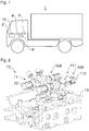
- the FIG. 1 shows a designed as a truck motor vehicle 1.
- another commercial vehicle such as a bus, or another motor vehicle may be provided.
- the motor vehicle 1 has an internal combustion engine 2 with a variable valve train 10.
- the motor vehicle 1 also has a positioning device 4, a navigation system 5 and a driver assistance system 6.
- the internal combustion engine 2 may be designed, for example, as a diesel, gasoline or gas engine.
- the intake and exhaust valves (charge cycle valves) of the engine 2 are operated by a variable valve train 10.
- the variable valve train 10 allows adjustment of the timing of the charge exchange valves.
- the charge exchange valves can be adjusted cylinder-selectively.
- the location determination device 4 makes it possible to determine a current position of the motor vehicle 1.
- the standard determination device 4 may, for example, be a satellite location determination device, in particular a GPS (global positioning system) device.
- the navigation system 5 enables navigation of the commercial vehicle 1 based on the current position of the utility vehicle and a route that is readable from a route memory.
- the travel route may be determined, for example, based on a destination input by a user.
- a navigation database of the navigation system 5 also operationally relevant road characteristics of the roads stored in the route memory can be stored.
- the operational road characteristics may generally affect operation of the internal combustion engine.
- the information stored in the route memory information can be wirelessly, for example, over the Internet, or wired, for example, via appropriate media to be updated.
- the driver assistance system 6 can enable a partial or complete automation of the driving operation of the motor vehicle 1.
- the driver assistance system 6 can in particular be designed as a cruise control system, preferably a proximity cruise control system.
- the driver assistance system 6 can automatically control, in particular taking into account the current position of the motor vehicle 1 and the upcoming route, an operation or an operating aspect of the motor vehicle 1.
- the driver assistance system 6 may be a satellite positioning device-controlled cruise control system, for example a GPS cruise control system.
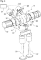
- the FIG. 2 shows a variable valve train 10.
- the variable valve train 10 includes an intake camshaft 12 and an exhaust camshaft 112.
- the intake camshaft 12 and the exhaust camshaft 112 are arranged as overhead camshafts.
- the intake camshaft 12 and the exhaust camshaft 112 form a double camshaft system.
- the double camshaft system is configured as a so-called double overhead camshaft (DOHC) system because the intake camshaft 12 and the exhaust camshaft 112 are located above a cylinder head 13 of the engine.
- DOHC double overhead camshaft
- SOHC single overhead camshaft
- the intake camshaft 12 and / or the exhaust camshaft 112 may also be arranged as an underlying camshaft. It is also conceivable that one or more mixed camshafts are provided for actuating intake and exhaust valves.
- At least one shift cam system 11, 111 is arranged on the intake camshaft 12 and the exhaust camshaft 112, respectively.
- the sliding cam system 11 of the intake-side valvetrain 10A is described with reference to FIGS Figures 3 and 4 described in more detail.
- the sliding cam system 111 of the exhaust-side valvetrain 10B is described with reference to FIGS FIGS. 5 to 7 described in more detail.
- variable valve train 10A In the FIG. 3 the intake side variable valve train 10A is shown.
- the variable valve train 10A has the intake camshaft 12 and a cam carrier 14.
- the variable valve train 10A has a transmission device 16 and first and second inlet valves 20 and 22.
- the variable valve train 10A has a first actuator 24 and a second actuator 26.
- the cam carrier 14, the transmission device 16 and the actuators 24 and 26 form a sliding cam system 11.
- the intake camshaft 12 actuates the input valves 20 and 22.
- the cam carrier 14 On the intake camshaft 12, the cam carrier 14 is arranged rotationally fixed.
- the cam carrier 14 is additionally arranged axially displaceable along a longitudinal axis of the intake camshaft 12.
- the cam carrier 14 may be axially displaceable between a first stop 28 and a second stop 30.
- a plurality of sliding cam systems 11 are provided on the intake camshaft 12 so that a sliding cam system 11 for cylinder-selective actuation of the at least one intake valve 20, 22 of the respective cylinder is available for each cylinder of the internal combustion engine.
- the cam carrier 14 has two cams 32 and 34 which are offset from each other in a longitudinal direction of the cam carrier 14 and the intake camshaft 12.
- the first cam 32 and the second cam 34 are disposed in a central portion of the cam carrier 14.
- the first cam 32 and the second cam 34 adjoin one another.
- the first cam 32 is configured to operate the intake valves 20 and 22 in a normal operation. In normal operation, the intake valves 20 and 22 close a piston movement in the region of a bottom dead center at the end of the intake stroke according to a diesel or Otto cycle process.
- the second cam 34 is designed for operation with a preferred closing time in relation to the normal operation.
- the second cam 34 is designed in particular for a mill operation, in which in a region before the bottom dead center of the piston movement according to a Miller cycle, the inlet valve is closed earlier than in a normal operation (diesel or Otto cycle process).
- intake valves 20, 22 close earlier. This allows less air into the combustion chamber.
- the reduced work can increase fuel efficiency in certain load ranges, i. H. a fuel consumption can be lowered.
- the Miller operation can also be used to increase an exhaust gas temperature.
- the fact that less air enters the combustion chamber, a combustion air ratio ⁇ can be reduced with the same fuel injection.
- the fuel-air mixture is thereby richer or richer. The combustion of the richer mixture leads to an increase in the exhaust gas temperature.
- the cam carrier 14 also has a first cam-free section 38 and a second cam-free section 40.
- the first cam-free portion 38 and the second cam-free portion 40 are disposed at opposite ends of the cam carrier 14.
- a first engagement track (shift gate) 42 extends spirally about a longitudinal axis of the cam carrier 14.
- a second engagement track (shift gate) 44 extends spirally around the longitudinal axis of the cam carrier 14th
- the actuators 24 and 26 with extendable elements can selectively engage in the engagement tracks 42, 44.
- the first actuator 24 may selectively engage the first engagement track 42 for shifting the cam carrier 14 from a first axial position to a second axial position.
- the cam carrier 14 In the first axial position of the cam carrier 14 abuts against the second stop 30.
- the cam carrier 14 In the second axial position of the cam carrier 14 abuts against the first stop 28.
- the cam carrier 14 is shown in the first axial position.
- the second actuator 26 in turn can selectively engage in the second engagement track 44. Then, the cam carrier 14 is shifted from the second axial position to the first axial position.
- the first actuator 24 and the second actuator 26 are driven by a control unit 27 shown schematically.
- the control unit 27 may be part of the driver assistance system 6 (see FIG. 1 ) or be connected to the driver assistance system 6.
- the displacement is triggered by the extended element of the respective actuator 24, 26 being stationary relative to an axial direction of the intake camshaft 12. Consequently, will the slidable cam carrier 14 is displaced in a longitudinal direction of the intake camshaft 12 due to the spiral shape of the engaging tracks 42, 44 when the extended element engages with the respective engagement track 42, 44.
- the displaceable element of the respective actuator 24, 26 is guided by the respective engagement track 42, 44 opposite to the extension direction and thus retracted. The displaceable element of the respective actuator 24, 26 comes out of engagement with the respective engagement track 42, 44th
- the transfer device 16 establishes an operative connection between the cam carrier 14 and the inlet valves 20, 22.
- the intake valves 20, 22 are operated (opened) when the first cam 32 or the second cam 34 presses the transfer device 16 down.
- the first transfer device 16 When the cam carrier 14 is in the first axial position, the first transfer device 16 is operatively connected between the first cam 32 and the intake valves 20, 22. In other words, the transfer device 16 in the first axial position of the cam carrier 14 is not operatively connected between the cam carrier 14 second cams 34 and the intake valves 20, 22. The intake valves 20, 22 are operated according to a contour of the first cam 32. In the second axial position of the cam carrier 14, the transfer device 16 is operatively connected between the second cam 34 and the intake valves 20, 22, which are operated in accordance with a contour of the second cam 34.
- the transfer device 16 is formed as a drag lever. In other embodiments, the transfer device 16 may be formed as a rocker arm or plunger. In some embodiments, the transfer device 16 may include a cam follower, for example in the form of a rotatable roller.
- the locking device 46 has an elastic element 48 and a blocking body 50.
- the elastic member 48 is disposed in a blind hole of the intake camshaft 12.
- the elastic member 48 biases the locking body 50 against the cam carrier 14.
- first and second recesses 52 and 54 are arranged.
- the blocking body 50 is, for example, pressed into the first recess 52 when the cam carrier 14 is in the first axial position.
- the blocking body 50 is pressed into the second recess 54.
- variable valve train 10B includes the exhaust camshaft 112 and a cam carrier 114.
- variable valve train 10B includes first and second transfer devices 116 and 118 and first and second exhaust valves 120 and 122.
- variable valve train 10B has a first actuator 124 and a second actuator 126.
- the cam carrier 114, the transmission devices 116 and 118 and the actuators 124 and 126 form a sliding cam system 111.
- a plurality of sliding cam systems 111 are provided, so that for each cylinder of the internal combustion engine, a sliding cam system 111 is available for cylinder-selective actuation of the at least one exhaust valve 120, 122 of the respective cylinder.
- the cam carrier 114 On the exhaust camshaft 112, the cam carrier 114 is arranged rotationally fixed.
- the cam carrier 114 is additionally arranged to be axially displaceable along a longitudinal axis of the exhaust camshaft 112.
- the cam carrier 114 may be axially displaceable between a first stop 128 and a second stop 130.
- the cam carrier 114 has three cams 132, 134 and 136 which are offset from each other in a longitudinal direction of the cam carrier 114 and the exhaust camshaft 112.
- the first cam 132 is disposed at a first end of the cam carrier 114 and configured for normal operation, as described in detail later by way of example.
- the second cam 134 is disposed adjacent to the first cam 132 and configured for engine braking operation, as also described in detail later by way of example.
- the engine braking operation may be used to slow down and / or brake the motor vehicle when going downhill.
- the engine braking operation may additionally be used during a shift-up assist operation.
- the third cam 136 is spaced from the second cam 134 and the second end of the cam carrier 114.
- the third cam 136 is designed for normal operation.
- the third cam 136 is shaped like the first cam 132.
- the cam carrier 114 also has a first cam-free section 138 and a second cam-free section 140.
- the first cam-free portion 138 is disposed at the second end of the cam carrier 114.
- the second cam-free portion 140 is disposed between the second cam 134 and the third cam 136.
- a first engagement track (shift gate) 142 extends spirally around one
- a second engagement track (shift gate) 144 spirally extends around the longitudinal axis of the cam carrier 114.
- the actuators 124 and 126 with extendable elements may selectively engage the engagement tracks 142, 144.
- the first actuator 124 may selectively engage the first engagement track 142 for shifting the cam carrier 114 from one axial position to another axial position.
- the cam carrier 114 bears against the second stop 130.
- the cam carrier 114 bears against the first stop 128.
- the cam carrier 114 is shown in the first axial position.
- the second actuator 126 in turn may selectively engage the second engagement track 144. Then, the cam carrier 114 is shifted from the first axial position to the second axial position.
- the first actuator 124 and the second actuator 126 are controlled by the control unit 27 shown schematically.
- the displacement is triggered by the extended member of the respective actuator 124, 126 being stationary with respect to an axial direction of the exhaust camshaft 112.
- the slidable cam carrier 114 is displaced in a longitudinal direction of the exhaust camshaft 112 due to the spiral shape of the engaging tracks 142, 144 when the extended member engages the respective engaging track 142, 144.
- the displaceable element of the respective actuator 124, 126 is guided by the respective engagement track 142, 144 opposite to the extension direction and thus retracted.
- the displaceable element of the respective actuator 124, 126 is disengaged from the respective engagement track 142, 144.
- the first transmission device 116 and the second transmission device 118 establish an operative connection between the cam carrier 114 and the outlet valves 120, 122.
- the first exhaust valve 120 is actuated (opened) when the first cam 132 or the second cam 134 pushes the first transmission device 116 downward.
- the second exhaust valve 122 is operated (opened) when the third cam 136 pushes the second transmission device 118 downward.
- the first transmission device 116 When the cam carrier 114 is in the first axial position (as in FIGS FIGS. 1 to 4 shown), the first transmission device 116 is in operative connection between the first Cam 132 and the first exhaust valve 120. In other words, in the first axial position of the cam carrier 114, the first transmission device 116 is not operatively connected between the second cam 134 and the first exhaust valve 120. The first exhaust valve 120 becomes in accordance with a contour of the first cam 132 actuated. In the second axial position of the cam carrier 114, the first transmission device 116 is operatively connected between the second cam 134 and the first exhaust valve 120. The first exhaust valve 120 is operated in accordance with a contour of the second cam 134.
- the second transfer device 118 In the first axial position of the cam carrier 114, the second transfer device 118 is operatively connected between the third cam 136 and the second exhaust valve 122.
- the second exhaust valve 122 is operated in accordance with a contour of the third cam 136.
- the second transfer device 118 In the second axial position of the cam carrier 114, the second transfer device 118 does not actuate the second exhaust valve 122.
- a contact portion 118A of the second transmission device 118 In the second axial position of the cam carrier 114, a contact portion 118A of the second transmission device 118 is at the same axial position with respect to the exhaust camshaft 112 as the first cam portion 138.
- the first cam free portion 138 has no protrusion for actuating the second transmission device 118.
- the second exhaust valve 122 When the cam carrier 114 is in the second axial position, the second exhaust valve 122 is not actuated.
- the first cam-free portion 138 thus has two functions. On the one hand, the first cam-free portion 138 receives the first guide track 142. On the other hand, the first cam-free portion 138 is for no actuation of the second exhaust valve 142 in the second axial position of the cam carrier 114. This functional integration is favorable for space reasons.
- first transfer device 116 and the second transfer device 118 are each configured as a drag lever.
- the transmission devices 116 and 118 may be formed as rocker arms or plungers.
- the transfer devices 116 and 118 may include cam followers, for example in the form of rotatable rollers.
- the locking device 146 has an elastic element 148 and a blocking body 150.
- the elastic member 148 is disposed in a blind hole of the exhaust camshaft 112.
- the elastic member 148 biases the locking body 150 against the cam carrier 114.
- first and second recesses 152 and 154 arranged in an inner peripheral surface of the cam carrier 114.
- the locking body 150 is pressed into the first recess 152 when the cam carrier 114 is in the first axial position.
- the blocking body 150 is pressed into the second recess 154.
- FIG. 7 shows a complete four-stroke cycle consisting of compression, expansion, ejection and suction.
- the curve A describes the profile of the cylinder pressure in engine braking operation when the second cam 134 is in operative connection with the first exhaust valve 120.
- the curve B shows the course of the valve lift of the first exhaust valve 120 when the first cam 132 is in communication with the first exhaust valve 120 (i.e., during normal operation).
- the third curve C shows the course of the valve lift of an intake valve both during normal operation and in engine braking operation.
- the curve D shows the course of the valve lift of the first exhaust valve 120 when the second cam 134 is in operative communication with the first exhaust valve 120 (i.e., during engine braking operation).
- Curve B shows that the exhaust valve is open during normal operation during the exhaust stroke.
- Curve C shows that the intake valve is open in normal operation and in braking operation during the intake stroke (intake stroke).
- the curve D shows that the exhaust valve at the end of the compression stroke in the range of top dead center at about 60 ° CA to 100 ° CA before top dead center is slightly opened.
- the exhaust valve is opened further and closes at the end of the expansion stroke approximately at bottom dead center.
- the opening of the exhaust valve at the end of the compression stroke causes the compressed air in the cylinder to be pushed through the opened exhaust valve into the exhaust system through the piston moving toward top dead center.
- the compression work previously done brakes the crankshaft and thus the internal combustion engine.
- the cylinder pressure initially increases in the compression stroke, but then drops due to the opening of the exhaust valve even before top dead center (see curve A).
- the open exhaust valve during the expansion stroke causes air from the exhaust pipes to be drawn back into the cylinder.
- the cylinder is substantially filled with air from the exhaust system.
- the curve D also shows that the exhaust valve initially remains closed after reaching bottom dead center at the end of the expansion stroke.
- the exhaust valve opens in the region of top dead center.
- the opening is again at about 60 ° CA to 100 ° CA before top dead center.
- the closed exhaust valve during the exhaust stroke causes the air sucked in the expansion stroke to be compressed by performing work.
- the cylinder pressure increases (curve A).
- the Vergessarbeit brakes the crankshaft and thus the internal combustion engine.
- the opening of the exhaust valve at the end of the exhaust stroke causes the air to be pushed into the exhaust system through the opened exhaust valve.
- the cylinder is again filled with air through the or the open intake valves (curve C). The cycle starts again.
- the use of the second cam to control the exhaust valve results in a double compression with subsequent decompression, thus ensuring engine braking functionality.
- the engine braking operation during a shift-up assist operation at a gear shift may be used to shorten a shift duration of an automatic transmission.
- a speed of the engine can be lowered very quickly.
- a turbocharger speed and turbocharger boost pressure during upshifting can be positively affected so that no or only a small turbo lag occurs after the higher gear engagement.
- valve lift of the exhaust valve is lower in braking mode (curve D) than in normal mode (curve B).
- the valve lift is also in two stages when opening the exhaust valve in the compression and expansion stroke.
- FIG. 8 shows an exemplary operating method for the driver assistance system 6 (see FIG. 1 ).
- step S2 a current position of the motor vehicle is determined.
- the positioning device 4 see FIG. 1 .
- the upcoming route is determined in step S4.
- the route can, for example, from the route memory of the navigation system 5 (see FIG. 1 ) or received directly via a data connection.
- the operationally relevant road properties are determined in step S6.
- the road properties can for example be read from a navigation database or received via a data connection.
- Examples of operational road characteristics are a road topology, such as a grade, a grade and / or a curve of the road, and a roadside traffic control, in particular a speed limit and / or a right of way.
- Another possible operational road characteristic is the current traffic situation, for example congestion, on the upcoming route.
- a driving recommendation is determined by the driver assistance system 6 in step S8.
- the driver of the motor vehicle can be informed of the driving recommendation.
- the information of the motor vehicle driver can in particular the acceptance of the driver assistance system 6 (see FIG. 1 ) increase.
- the driver assistance system 6 (see FIG. 1 ).
- Implement the driving recommendation automatically.
- the driving recommendation for example, the operation of the motor vehicle 1 in a low load range, have an automatic gear change to a higher gear or a continuous braking operation.
- step S10 the variable valve train 10 (see FIG. 1 ).
- At least one shift cam system 11 of the intake side may be driven to switch to a Miller control time by the control unit 27 (see FIG Figures 3 and 4 ).
- fuel can thus be saved, a temperature of the exhaust gas can be variably adjusted, a point of operation of a turbocharger can be variably adjusted and / or an air throughput can be variably adjusted.
- the number of intake valves 20, 22 in miller operation can be adjusted, for example, depending on a desired exhaust gas temperature, a desired air flow rate, a load of the internal combustion engine and / or an operating point of the turbocharger of the internal combustion engine.
- an automatic switch to mill operation can be useful.
- a low load of the engine is expected for a certain period of time due to the upcoming route. This may be the case for an upcoming route with a small slope or no gradient.
- a fuel efficiency can be improved in the low load range, since less work is required for the change of charge.
- At least one exhaust-side shift cam system 111 may be driven by the control unit 27 to switch to engine braking operation (see FIG Figures 5 and 6 ).
- the sliding cam system 111 can set the second cam 134 in operative connection with the first outlet valve 120 (see FIG Figures 5 and 6 ).
- At least one cylinder may be switched to engine braking mode.
- an adequate lowering of the speed of the motor vehicle can be made possible on time to reach the stretch of road with lowered maximum speed or upon reaching the construction site or the congestion.
- At least one exhaust-side shift cam system 111 may be switched to the upshift assistance mode when the operational road characteristics of the upcoming travel route require a gear shift to a higher gear.
- the time of the gear change can be significantly reduced in an automatic transmission by the shift-up assist mode because it allows a rapid reduction in the engine speed.
- the method of operating the driver assistance system 6 allows for anticipatory shifting behavior of an automatic transmission in combination with the thermodynamic aspects of the internal combustion engine.
- unnecessary switching operations of the sliding cam systems when driving through the engine map can be avoided.
Landscapes
- Engineering & Computer Science (AREA)
- Mechanical Engineering (AREA)
- Chemical & Material Sciences (AREA)
- Combustion & Propulsion (AREA)
- General Engineering & Computer Science (AREA)
- Transportation (AREA)
- Automation & Control Theory (AREA)
- Human Computer Interaction (AREA)
- Physics & Mathematics (AREA)
- General Physics & Mathematics (AREA)
- Output Control And Ontrol Of Special Type Engine (AREA)
- Control Of Vehicle Engines Or Engines For Specific Uses (AREA)
- Controls For Constant Speed Travelling (AREA)
Abstract
Description
- Die Erfindung betrifft ein Betriebsverfahren für ein Fahrerassistenzsystem und ein Kraftfahrzeug.
- Fahrerassistenzsysteme können in Kraftfahrzeugen zum Übernehmen bestimmter Aufgaben eingesetzt werden. Die Fahrerassistenzsysteme können dabei auf die Unterrichtung eines Fahrzeugführers beschränkt sein. Es ist allerdings auch möglich, dass Fahrerassistenzsysteme automatisch bestimmte Aspekte des Fahrbetriebs des Kraftfahrzeugs steuern. Zum Beispiel ermöglicht eine Geschwindigkeitsregelanlage das automatische Halten einer eingestellten Geschwindigkeit. Es sind auch sogenannte GPS-gesteuerte Geschwindigkeitsregelanlagen bekannt, die einen Streckenverlauf mit Steigungen und Gefälle im Voraus erfassen. Die Geschwindigkeitsregelanlage kann dann beispielsweise eine Fahrstufe und Geschwindigkeit im Sinne einer wirtschaftlichen Fahrweise anpassen und Rückschaltungen, wann immer es sinnvoll ist, unterdrücken.
- Ein Betriebsverfahren für ein Fahrerassistenz ist beispielsweise in der
DE 10 2010 048 323 A1 offenbart. Das Betriebsverfahren für ein Fahrerassistenzsystem unterstützt einen Fahrzeugführer eines Kraftfahrzeugs bei der Senkung eines Kraftstoffverbrauchs des Kraftfahrzeugs. Das Betriebsverfahren weist die folgenden Schritte auf: Bestimmung einer Fahrempfehlung zur Senkung des Kraftstoffverbrauchs des Kraftfahrzeugs; Ermittlung mindestens einer verbrauchsrelevanten Straßeneigenschaft einer Straße auf der bevorstehenden Fahrtroute des Kraftfahrzeugs, wobei die verbrauchsrelevante Straßeneigenschaft den Kraftstoffverbrauch des Kraftfahrzeugs beeinflusst; sowie Bestimmung der Fahrempfehlung, die aufgrund ihrer Darstellung über die zukünftige zeitliche Entwicklung geeignet ist, die Akzeptanz beim Fahrzeugführer zu erhöhen und Funktionsweise des Fahrerassistenzsystems plausibel zu machen. - Der Erfindung liegt die Aufgabe zu Grunde, ein verbessertes Betriebsverfahren für ein Fahrerassistenzsystem vorzusehen. Insbesondere sollen weitere Potenziale für die Kraftstoffeinsparung und den Betrieb von Abgasnachbehandlungssystemen ausgeschöpft werden.
- Die Aufgabe wird gelöst durch ein Betriebsverfahren für ein Fahrerassistenzsystem und ein Kraftfahrzeug gemäß den unabhängigen Ansprüchen. Vorteilhafte Weiterbildungen sind in den abhängigen Ansprüchen und der Beschreibung angegeben.
- Das Betriebsverfahren ist für ein Fahrerassistenzsystem, insbesondere eine Geschwindigkeitsregelanlage, vorzugsweise einen Satellitenstandortbestimmungsvorrichtung-gesteuerte Geschwindigkeitsregelanlage, eines Kraftfahrzeugs, vorzugsweise Nutzfahrzeugs, vorgesehen. Das Kraftfahrzeug weist einen Verbrennungsmotor mit einem variablen Ventiltrieb, insbesondere mit einer Mehrzahl von Schiebenockensystemen, zum Verstellen der Ventilsteuerkurven der Ein- und/oder Auslassventile des Verbrennungsmotors auf. Das Verfahren weist das Ermitteln mindestens einer betriebsrelevanten Straßeneigenschaft einer Straße auf einer bevorstehenden Fahrtroute des Kraftfahrzeugs auf. Die betriebsrelevante Straßeneigenschaft beeinflusst einen Betrieb des Verbrennungsmotors des Kraftfahrzeugs. Das Verfahren weist das Bestimmen einer Fahrempfehlung in Abhängigkeit von der betriebsrelevanten Straßeneigenschaft auf der bevorstehenden Fahrtroute des Kraftfahrzeugs und das Einstellen des variablen Ventiltriebs in Abhängigkeit von der bestimmten Fahrempfehlung auf.
- Durch die Einstellung des variablen Ventiltriebs in Abhängigkeit von der bestimmten Fahrempfehlung können bisher nicht ausgeschöpfte Potenziale für die Kraftstoffeinsparung und den Betrieb von Abgasnachbehandlungssystemen ausgeschöpft werden.
- Insbesondere kann eine betriebsrelevante Straßeneigenschaft einen Betrieb einer Abgasnachbehandlungseinrichtung, zum Beispiel eines SCR- oder Oxidationskatalysators, eine Last des Verbrennungsmotors und/oder einen Kraftstoffverbrauch des Verbrennungsmotors beeinflussen.
- In einer besonders bevorzugten Ausführungsform ermöglicht der variable Ventiltrieb eine Verstellung der Ein- und/oder Auslassventile innerhalb eines vorbestimmten Stellbereichs. Die Fahrempfehlung kann dann zusätzlich in Abhängigkeit von dem vorbestimmten Stellbereich bestimmt.
- In einerweiteren Ausführungsform weist das Betriebsverfahren das akustische, visuelle und/oder haptische Unterrichten eines Fahrzeugführers des Kraftfahrzeugs über die Fahrempfehlung auf. Damit kann die Akzeptanz gegenüber dem Fahrerassistenzsystem verbessert werden.
- Alternativ oder zusätzlich weist das Betriebsverfahren das automatische Umsetzen der Fahrempfehlung durch das Kraftfahrzeug und/oder das Fahrerassistenzsystem auf. Folglich kann der Fahrzeugführer des Kraftfahrzeugs entlastet werden.
- In einer Ausführungsvariante weist die betriebsrelevante Straßeneigenschaft ein Topologie, insbesondere ein Gefälle, eine Steigung und/oder Kurve der Straße, der bevorstehenden Fahrtroute auf. Somit kann die Fahrempfehlung der Topologie angepasst werden.
- In einer weiteren Ausführungsvariante weist die betriebsrelevante Straßeneigenschaft eine auf der Straße geltende Verkehrsregelung, insbesondere eine Geschwindigkeitsbegrenzung und/oder eine Vorfahrtsregelung, auf. Folglich kann die Fahrempfehlung an die geltende Verkehrsregelung angepasst werden.
- Zusätzlich oder alternativ kann die die betriebsrelevante Straßeneigenschaft eine aktuelle Verkehrssituation aufweisen. Dies hat den Vorteil, dass die Fahrempfehlung an die aktuelle Verkehrssituation angepasst werden kann.
- In einem Ausführungsbeispiel weist das Verfahren das Ermitteln einer aktuellen Position des Kraftfahrzeugs mittels einer Standortbestimmungsvorrichtung, insbesondere mittels einer Satellitenstandortbestimmungsvorrichtung, auf.
- In einem weiteren Ausführungsbeispiel weist das Verfahren das Ermitteln der bevorstehenden Fahrtroute des Kraftfahrzeugs in Abhängigkeit von einer aktuellen Position des Kraftfahrzeugs auf. Insbesondere kann die bevorstehende Fahrtroute des Kraftfahrzeugs aus einem Routenspeicher eines Navigationssystems ausgelesen und/oder beispielsweise über eine Datenverbindung empfangen werden.
- In einer Weiterbildung weist das Verfahren das Auslesen der betriebsrelevanten Straßeneigenschaften aus einer Navigationsdatenbank und/oder das Empfangen der betriebsrelevanten Straßeneigenschaften beispielsweise über eine Datenverbindung auf.
- In einer weiteren Ausführungsvariante weist das Verfahren das Bestimmen der Fahrempfehlung in Abhängigkeit von der betriebsrelevanten Straßeneigenschaft auf der bevorstehenden Fahrtroute des Kraftfahrzeugs und einer aktuellen Position des Kraftfahrzeugs auf.
- In einer bevorzugten Ausführungsform stellt der variable Ventiltrieb die Steuerzeiten der Ein- und/oder Auslassventile in Abhängigkeit von der bestimmten Fahrempfehlung zylinderselektiv ein. Damit können je nach Anforderung kein Ventil, mehrere Ventile oder alle Ventile in Abhängigkeit von der Fahrempfehlung verstellt werden. Damit können weitere Potenziale insbesondere bezüglich eines kraftstoffeffizienten Verbrauchs ausgeschöpft werden.
- Zum Beispiel kann der variable Ventiltrieb die Steuerzeiten nur für einen Teil der Ein- und/oder Auslassventile in Abhängigkeit von der bestimmten Fahrempfehlung verstellen.
- In einem Ausführungsbeispiel weist die Fahrempfehlung einen, insbesondere automatischen, Gangwechsel in einen höheren Gang auf. Der variable Ventiltrieb wird dann in einen Hochschaltunterstützungsbetrieb zum Verkürzen einer Dauer des Gangwechsels geschaltet.
- Der höhere Gang kann insbesondere eine höhere Übersetzung als ein aktueller Gang aufweisen.
- In einem weiteren Ausführungsbeispiel weist die Fahrempfehlung einen Dauerbremsbetrieb des Verbrennungsmotors auf. Der variable Ventiltrieb kann dann in einen Motorbremsbetrieb geschaltet werden.
- In einer bevorzugten Weiterbildung wird im Hochschaltunterstützungsbetrieb und/oder im Motorbremsbetrieb mindestens ein Auslassventil des Verbrennungsmotors im Verdichtungstakt und/oder im Ausschubtakt zur Kompression von Luft zunächst geschlossen gehalten und vor Erreichen eines oberen Totpunkts einer Kolbenbewegung zur Dekompression der verdichteten Luft geöffnet. Damit kann eine erhebliche Drehzahlabsenkung innerhalb einer kurzen Zeit ohne Betätigung einer Abgasdrosselklappe und einer damit einhergehenden Verschlechterung des Betriebs eines Turboladers erreicht werden.
- In einer Ausführungsform wird eine Anzahl von Auslassventilen im Hochschaltunterstützungsbetrieb in Abhängigkeit von der betriebsrelevanten Straßeneigenschaft auf der bevorstehenden Fahrtroute des Kraftfahrzeugs, einer erforderlichen Drehzahlabsenkung für den Gangwechsel, einer erforderlichen Drehmomenterhöhung für den Gangwechsel, einer gewünschten Dauer des Gangwechsels, einer gewünschten Turboladerdrehzahl und/oder eines gewünschten Ladedrucks bestimmt.
- Alternativ oder zusätzlich wird eine Anzahl von Auslassventilen im Motorbremsbetrieb in Abhängigkeit von der betriebsrelevanten Straßeneigenschaft auf der bevorstehenden Fahrtroute des Kraftfahrzeugs, insbesondere einem Gefälle und/oder einer Geschwindigkeitsbegrenzung, bestimmt. Somit können beispielsweise je nach Gefälle oder erforderlicher Geschwindigkeitsabsenkung eines, mehrere oder alle Auslassventile im Motorbremsbetrieb betrieben werden.
- Im Motorbremsbetrieb und/oder Hochschulunterstützungsbetrieb kann insbesondere auf ein Einspritzen von Kraftstoff verzichtet werden und/oder eine Betätigung des mindestens einen Einlassventils unverändert bleiben.
- Im Motorbremsbetrieb und/oder Hochschulunterstützungsbetrieb kann das Auslassventil insbesondere zwischen 100° KW und 60° KW vor dem Erreichen des oberen Totpunkts geöffnet werden. Alternativ oder zusätzlich kann das Auslassventil nach dem Öffnen im Ausschubtakt im Bereich zwischen dem oberem Totpunkt und 30° KW nach dem oberen Totpunkt schließen. Alternativ oder zusätzlich kann das Auslassventil nach dem Öffnen im Verdichtungstakt im Bereich zwischen dem unteren Totpunkt und 30° KW nach dem unteren Totpunkt schließen. Damit können ein wirkungsvoller Motorbremsbetrieb und Hochschulunterstützungsbetrieb dargestellt werden.
- In einer weiteren Ausführungsform weist die Fahrempfehlung das Anpassen einer Abgastemperatur, das Anpassen eines Betriebspunkts eines Turboladers des Verbrennungsmotors, das Anpassen eines Luftdurchsatzes und/oder das Betreiben des Verbrennungsmotors in einem Schwachlastbereich auf. Der variable Ventiltrieb kann dann in einen Millerbetrieb geschaltet werden.
- Der Schwachlastbereich kann sich insbesondere unterhalb eines Mitteldrucks des Verbrennungsmotors von 6 bar, 5 bar oder 4 bar erstrecken.
- Im Millerbetrieb kann insbesondere ein Schließzeitpunkt eines Einlassventils gegenüber einem Normalbetrieb vorgezogen werden. Im Normalbetrieb schließt das Einlassventil im Bereich des Erreichens eines unteren Totpunkts einer Kolbenbewegung am Ende des Einlasstaktes. Im Millerbetrieb liegt der Schließzeitpunkt des Einlassventils vor dem Erreichen des unteren Totpunkts der Kolbenbewegung. Im Millerbetrieb kann der Schließzeitpunkt insbesondere gleich oder mehr als 5° KW (Kurbelwinkel), 10° KW, 20° KW oder 30° KW vor dem Schließzeitpunkt im Normalbetrieb liegen.
- In einer Weiterbildung wird eine Anzahl von Einlassventilen im Millerbetrieb in Abhängigkeit von der betriebsrelevanten Straßeneigenschaft auf der bevorstehenden Fahrtroute des Kraftfahrzeugs, einer gewünschten Abgastemperatur, einem gewünschten Luftdurchsatz, einer Last des Verbrennungsmotors und/oder einem Betriebspunkts eines Turboladers des Verbrennungsmotors bestimmt. Folglich können je nach Situation nur eines, mehrere oder alle Einlassventile im Millerbetrieb betrieben werden.
- In einem Ausführungsbeispiel weist jedes Schiebenockensystem einen auf einer Nockenwelle des Verbrennungsmotors drehfest und axial verschiebbar angeordneten Nockenträger mit einem ersten Nocken für einen Normalbetrieb und einen in einer Längsrichtung der Nockenwelle versetzt angeordneten zweiten Nocken für einen Motorbremsbetrieb, einen Hochschaltunterstützungsbetrieb und/oder einen Millerbetrieb auf. Das Schiebenockensystem setzt wahlweise den ersten Nocken und mindestens ein Auslassventil und/oder Einlassventil in Wirkverbindung oder den zweiten Nocken und mindestens ein Auslassventil und/oder Einlassventil in Wirkverbindung. Die Schiebenockensysteme bieten eine schnelle und zuverlässige Möglichkeit zum Umschalten zwischen verschiedenen Ventilsteuerkurven.
- Die Erfindung betrifft auch ein Kraftfahrzeug, insbesondere Nutzfahrzeug. Das Nutzfahrzeug kann beispielsweise ein Omnibus oder ein Lastkraftwagen sein. Das Kraftfahrzeug weist eine Standortbestimmungsvorrichtung, insbesondere Satellitenstandortbestimmungsvorrichtung, auf. Das Kraftfahrzeug weist ein Fahrerassistenzsystem auf, das dazu ausgebildet ist, das Betriebsverfahren nach einem der vorherigen Ansprüche durchzuführen.
- In einer Weiterbildung weist das Kraftfahrzeug ein Navigationssystem und/oder einen variablen Ventiltrieb für einen mehrere Zylinder aufweisenden Verbrennungsmotor des Kraftfahrzeugs auf. Der variable Ventiltrieb weist mindestens ein Einlassventil und/oder Auslassventil auf. Der variable Ventiltrieb weist mindestens eine Nockenwelle und mehrere Schiebenockensysteme für die mehreren Zylinder auf. Jedes Schiebenockensystem weist einen Nockenträger, der auf der Nockenwelle drehfest und axial verschiebbar angeordnet ist und einen ersten Nocken und einen zweiten Nocken aufweist, auf. Der erste Nocken und der zweite Nocken sind in einer Längsrichtung der Nockenwelle versetzt angeordnet.
- In einer weiteren Ausführungsform weist der variable Ventiltrieb einen Phasensteller auf. Der Phasensteller ist dazu ausgebildet, einen Drehwinkel der Nockenwelle relativ zu einem Drehwinkel einer Kurbelwelle des Verbrennungsmotors zu verstellen. Somit kann der Phasensteller eine Verstellung der Steuerzeiten für die jeweiligen Ein- und/oder Auslassventile ermöglichen. Der Phasenversteller kann beispielsweise als hydraulischer Phasenversteller, insbesondere als ein Schwenkmotorphasenversteller, ausgebildet sein.
- Die zuvor beschriebenen bevorzugten Ausführungsformen und Merkmale der Erfindung sind beliebig miteinander kombinierbar. Weitere Einzelheiten und Vorteile der Erfindung werden im Folgenden unter Bezug auf die beigefügten Zeichnungen beschrieben. Es zeigen:
- Figur 1
- eine schematische Ansicht eines Kraftfahrzeugs;
- Figur 2
- eine perspektivische Ansicht eines variablen Ventiltriebs;
- Figur 3
- eine perspektivische Ansicht eines einlassseitigen variablen Ventiltriebs;
- Figur 4
- eine Längsschnittansicht des einlassseitigen variablen Ventiltriebs;
- Figur 5
- eine perspektivische Ansicht eines auslassseitigen variablen Ventiltriebs;
- Figur 6
- eine Längsschnittansicht des auslassseitigen variablen Ventiltriebs;
- Figur 7
- ein Diagramm mit beispielhaften Ventilsteuerkurven und einem Zylinderdruckverlauf; und
- Figur 8
- ein beispielhaftes Betriebsverfahren für ein Fahrerassistenzsystem.
- Die in den Figuren gezeigten Ausführungsformen stimmen zumindest teilweise überein, so dass ähnliche oder identische Teile mit den gleichen Bezugszeichen versehen sind und zu deren Erläuterung auch auf die Beschreibung der anderen Ausführungsformen bzw. Figuren verwiesen wird, um Wiederholungen zu vermeiden.
- Die
Figur 1 zeigt ein als Lastkraftwagen ausgebildetes Kraftfahrzeug 1. Alternativ kann auch ein anderes Nutzfahrzeug, wie beispielsweise ein Omnibus, oder ein anderes Kraftfahrzeug vorgesehen sein. - Das Kraftfahrzeug 1 weist einen Verbrennungsmotor 2 mit einem variablen Ventiltrieb 10 auf. Das Kraftfahrzeug 1 weist ferner eine Standortbestimmungsvorrichtung 4, ein Navigationssystem 5 und ein Fahrerassistenzsystem 6 auf.
- Der Verbrennungsmotor 2 kann beispielsweise als ein Diesel-, Benzin- oder Gasmotor ausgebildet sein. Die Einlass- und Auslassventile (Ladungswechselventile) des Verbrennungsmotors 2 werden von einem variablen Ventiltrieb 10 betätigt. Der variable Ventiltrieb 10 ermöglicht eine Verstellung der Steuerzeiten der Ladungswechselventile. Insbesondere können die Ladungswechselventile zylinderselektiv verstellt werden.
- Die Standortbestimmungsvorrichtung 4 ermöglicht die Bestimmung einer aktuellen Position des Kraftfahrzeug 1. Die Standardbestimmungsvorrichtung 4 kann beispielsweise eine Satellitenstandortbestimmungsvorrichtung, insbesondere eine GPS-Vorrichtung (engl. global positioning system), sein.
- Das Navigationssystem 5 ermöglicht eine Navigation des Nutzfahrzeugs 1 basierend auf der aktuellen Position des Nutzfahrzeugs und einer Fahrtroute, die aus einem Routenspeicher auslesbar ist. Die Fahrtroute kann beispielsweise basierend auf einem Fahrziel, das von ein Benutzer eingegeben wird, bestimmt werden. In einer Navigationsdatenbank des Navigationssystems 5 können ferner betriebsrelevante Straßeneigenschaften der im Routenspeicher gespeicherten Straßen gespeichert sein. Die betriebsrelevanten Straßeneigenschaften können allgemein einen Betrieb des Verbrennungsmotors beeinflussen. Die im Routenspeicher gespeicherten Informationen können drahtlos, zum Beispiel über das Internet, oder kabelgebundenen, zum Beispiel über entsprechende Datenträger, aktualisiert werden.
- Das Fahrerassistenzsystem 6 kann eine teilweise oder vollständige Automatisierung des Fahrbetriebs des Kraftfahrzeugs 1 ermöglichen. Das Fahrerassistenzsystem 6 kann insbesondere als eine Geschwindigkeitsregelanlage, vorzugsweise eine Abstandsgeschwindigkeitsregelanlage, ausgebildet sein. Das Fahrerassistenzsystem 6 kann insbesondere unter Berücksichtigung der aktuellen Position des Kraftfahrzeugs 1 und der bevorstehenden Fahrtroute einen Betrieb oder einen Betriebsaspekt des Kraftfahrzeugs 1 automatisch steuern. Insbesondere kann das Fahrerassistenzsystem 6 eine Satellitenstandortbestimmungsvorrichtung-gesteuerte Geschwindigkeitsregelanlage, zum Beispiel eine GPS-Geschwindigkeitsregelanlage, sein.
- Die
Figur 2 zeigt einen variablen Ventiltrieb 10. Der variable Ventiltrieb 10 weist eine Einlassnockenwelle 12 und ein Auslassnockenwelle 112 auf. Die Einlassnockenwelle 12 und die Auslassnockenwelle 112 sind als obenliegenden Nockenwellen angeordnet. Die Einlassnockenwelle 12 und die Auslassnockenwelle 112 bilden ein Doppelnockenwellensystem. Das Doppelnockenwellensystem ist als ein sogenanntes DOHC-System (engl. double overhead camshaft) ausgebildet, da die Einlassnockenwelle 12 und die Auslassnockenwelle 112 oberhalb eines Zylinderkopfes 13 des Verbrennungsmotors angeordnet sind. Alternativ könnte die Einlassnockenwelle 12 oder die Auslassnockenwelle 112 beispielsweise ein sogenanntes SOHC-System bilden (engl. single overhead camshaft). In anderen Ausführungsformen kann die Einlassnockenwelle 12 und/oder die Auslassnockenwelle 112 auch als untenliegende Nockenwelle angeordnet sein. Es ist ebenso denkbar, dass eine oder mehrere gemischte Nockenwellen zum Betätigen von Ein- und Auslassventilen vorgesehen sind. - Auf der Einlassnockenwelle 12 und der Auslassnockenwelle 112 ist jeweils mindestens ein Schiebenockensystem 11, 111 angeordnet. Das Schiebenockensystem 11 des einlassseitigen Ventiltriebs 10A ist unter Bezugnahme auf die
Figuren 3 und4 näher beschrieben. Das Schiebenockensystem 111 des auslassseitigen Ventiltriebs 10B ist unter Bezugnahme auf dieFiguren 5 bis 7 näher beschrieben. - In der
Figur 3 ist der einlassseitige variable Ventiltrieb 10A gezeigt. Der variable Ventiltrieb 10A weist die Einlassnockenwelle 12 und einen Nockenträger 14 auf. Zusätzlich weist der variable Ventiltrieb 10A eine Übertragungsvorrichtung 16 sowie ein erstes und zweites Einlassventil 20 und 22 auf. Zudem weist der variable Ventiltrieb 10A einen ersten Aktor 24 und einen zweiten Aktor 26 auf. Der Nockenträger 14, die Übertragungsvorrichtung 16 sowie die Aktoren 24 und 26 bilden ein Schiebenockensystem 11. Die Einlassnockenwelle 12 betätigt die Eingangsventile 20 und 22. - Auf der Einlassnockenwelle 12 ist der Nockenträger 14 drehfest angeordnet. Der Nockenträger 14 ist zusätzlich axial verschiebbar entlang einer Längsachse der Einlassnockenwelle 12 angeordnet. Der Nockenträger 14 kann zwischen einem ersten Anschlag 28 und einem zweiten Anschlag 30 axial verschiebbar sein.
- Auf der Einlassnockenwelle 12 sind mehrere Schiebenockensysteme 11 vorgesehen, sodass für jeden Zylinder des Verbrennungsmotors ein Schiebenockensystem 11 zur zylinderselektiven Betätigung des mindestens einen Einlassventils 20, 22 des jeweiligen Zylinders zur Verfügung steht.
- Der Nockenträger 14 weist zwei Nocken 32 und 34 auf, die in einer Längsrichtung des Nockenträgers 14 und der Einlassnockenwelle 12 voneinander versetzt sind. Der erste Nocken 32 und der zweite Nocken 34 sind in einem Mittelabschnitt des Nockenträgers 14 angeordnet. Der erste Nocken 32 und der zweite Nocken 34 grenzen aneinander.
- Der erste Nocken 32 ist zur Betätigung der Einlassventile 20 und 22 in einem Normalbetrieb ausgebildet. Im Normalbetrieb schließen die Einlassventile 20 und 22 am Ende des Einlasstakts im Bereich eines unteren Totpunkts einer Kolbenbewegung gemäß einem Diesel- oder Ottokreisprozess.
- Der zweite Nocken 34 ist für einen Betrieb mit vorgezogenem Schließzeitpunkt gegenüber dem Normalbetrieb ausgebildet. Der zweite Nocken 34 ist insbesondere für einen Millerbetrieb ausgebildet, bei dem in einem Bereich vordem unteren Totpunkt der Kolbenbewegung gemäß einem Miller-Kreisprozess das Einlassventil früher geschlossen wird als bei einem Normalbetrieb (Diesel- oder Ottokreisprozess).
- Im Millerbetrieb schließen die Einlassventile 20, 22 früher. Damit gelangt weniger Luft in den Brennraum. Dies führt einerseits dazu, dass der Verbrennungsmotor weniger Arbeit für den Ladungswechsel (d. h. Einlassen von Frischluft und Auslassen von Abgas) benötigt. Durch die verringerte Arbeit kann in bestimmten Lastbereichen eine Kraftstoffeffizienz erhöht, d. h. ein Kraftstoffverbrauch gesenkt, werden. Der Millerbetrieb kann auch dazu genutzt werden, eine Abgastemperatur zu erhöhen. Dadurch, dass weniger Luft in den Brennraum gelangt, kann bei gleichbleibender Kraftstoffeinspritzung ein Verbrennungsluftverhältnis λ verringert werden. Das Kraftstoff-Luft-Gemisch wird dadurch fetter oder reicher. Die Verbrennung des fetteren Gemischs führt zu einer Erhöhung der Abgastemperatur.
- Der Nockenträger 14 weist zudem einen ersten nockenfreien Abschnitt 38 und einen zweiten nockenfreien Abschnitt 40 auf. Der erste nockenfreie Abschnitt 38 und der zweite nockenfreie Abschnitt 40 sind an gegenüberliegenden Enden des Nockenträgers 14 angeordnet. Im ersten nockenfreien Abschnitt 38 erstreckt sich eine erste Eingriffsspur (Schaltkulisse) 42 spiralförmig um eine Längsachse des Nockenträgers 14. Im zweiten nockenfreien Abschnitt 40 erstreckt sich eine zweite Eingriffsspur (Schaltkulisse) 44 spiralförmig um die Längsachse des Nockenträgers 14.
- Zum Verschieben des Nockenträgers 14 zwischen den Anschlägen 28 und 30 können die Aktoren 24 und 26 mit ausfahrbaren Elementen (nicht im Detail gezeigt) selektiv in die Eingriffsspuren 42, 44 eingreifen. Im Einzelnen kann der erste Aktor 24 selektiv in die erste Eingriffsspur 42 zum Verschieben des Nockenträgers 14 von einer ersten Axialposition zu einer zweiten Axialposition eingreifen. In der ersten Axialposition liegt der Nockenträger 14 an dem zweiten Anschlag 30 an. In der zweiten Axialposition liegt der Nockenträger 14 an dem ersten Anschlag 28 an. In der
Figur 3 ist der Nockenträger 14 in der ersten Axialposition dargestellt. Der zweite Aktor 26 wiederum kann selektiv in die zweite Eingriffsspur 44 eingreifen. Dann wird der Nockenträger 14 von der zweiten Axialposition zu der ersten Axialposition verschoben. Der erste Aktor 24 und der zweite Aktor 26 werden von einer schematisch dargestellten Steuereinheit 27 angesteuert. Die Steuereinheit 27 kann Teil des Fahrerassistenzsystems 6 (sieheFigur 1 ) sein oder mit dem Fahrerassistenzsystem 6 verbunden sein. - Die Verschiebung wird dadurch ausgelöst, dass das ausgefahrene Element des jeweiligen Aktors 24,26 bezüglich einer Axialrichtung der Einlassnockenwelle 12 ortsfest ist. Folglich wird der verschiebbare Nockenträger 14 aufgrund der Spiralform der Eingriffsspuren 42, 44 in einer Längsrichtung der Einlassnockenwelle 12 verschoben, wenn das ausgefahrene Element in die jeweilige Eingriffsspur 42, 44 eingreift. Am Ende des Verschiebevorgangs wird das verschiebbare Element des jeweiligen Aktors 24, 26 von der jeweiligen Eingriffsspur 42, 44 entgegengesetzt zu der Ausfahrrichtung geführt und somit eingefahren. Das verschiebbare Element des jeweiligen Aktors 24, 26 gelangt außer Eingriff mit der jeweiligen Eingriffsspur 42, 44.
- Die Übertragungsvorrichtung 16 stellt eine Wirkverbindung zwischen dem Nockenträger 14 und den Einlassventilen 20, 22 her. Die Einlassventile 20, 22 werden betätigt (geöffnet), wenn der erste Nocken 32 oder der zweite Nocken 34 die Übertragungsvorrichtung 16 nach unten drückt.
- Befindet sich der Nockenträger 14 in der ersten Axialposition, ist die erste Übertragungsvorrichtung 16 in Wirkverbindung zwischen dem ersten Nocken 32 und den Einlassventilen 20, 22. Mit anderen Worten gesagt, ist die Übertragungsvorrichtung 16 in der ersten Axialposition des Nockenträgers 14 nicht in Wirkverbindung zwischen dem zweiten Nocken 34 und den Einlassventilen 20, 22. Die Einlassventile 20, 22 werden gemäß einer Kontur des ersten Nockens 32 betätigt. In der zweiten Axialposition des Nockenträgers 14 ist die Übertragungsvorrichtung 16 in Wirkverbindung zwischen dem zweiten Nocken 34 und den Einlassventilen 20, 22, die gemäß einer Kontur des zweiten Nockens 34 betätigt werden.
- In der dargestellten Ausführungsform ist die Übertragungsvorrichtung 16 als ein Schlepphebel ausgebildet. In anderen Ausführungsformen kann die Übertragungsvorrichtung 16 als Kipphebel oder Stößel ausgebildet sein. In einigen Ausführungsformen kann die Übertragungsvorrichtung 16 einen Nockenfolger, zum Beispiel in Form einer drehbaren Rolle, aufweisen.
- Unter Bezugnahme auf
Figur 4 ist eine Arretierungsvorrichtung 46 gezeigt. Die Arretierungsvorrichtung 46 weist ein elastisches Element 48 und einen Sperrkörper 50 auf. Das elastische Element 48 ist in einem Sackloch der Einlassnockenwelle 12 angeordnet. Das elastische Element 48 spannt den Sperrkörper 50 gegen den Nockenträger 14 vor. In einer Innenumfangsfläche des Nockenträgers 14 sind eine erste und zweite Ausnehmung 52 und 54 angeordnet. Zum Arretieren des Nockenträgers 14 wird der Sperrkörper 50 bspw. in die erste Ausnehmung 52 gedrückt, wenn der Nockenträger 14 in der ersten Axialposition ist. In der zweiten Axialposition des Nockenträgers 14 wird der Sperrkörper 50 in die zweite Ausnehmung 54 gedrückt. - In der
Figur 5 ist der auslassseitige variable Ventiltrieb 10B gezeigt. Der variable Ventiltrieb 10B weist die Auslassnockenwelle 112 und einen Nockenträger 114 auf. Zusätzlich weist der variable Ventiltrieb 10B eine erste und zweite Übertragungsvorrichtung 116 und 118 sowie ein erstes und zweites Auslassventil 120 und 122 auf. Zudem weist der variable Ventiltrieb 10B einen ersten Aktor 124 und einen zweiten Aktor 126 auf. Der Nockenträger 114, die Übertragungsvorrichtungen 116 und 118 sowie die Aktoren 124 und 126 bilden ein Schiebenockensystem 111. - Auf der Auslassnockenwelle 112 sind mehrere Schiebenockensysteme 111 vorgesehen, sodass für jeden Zylinder des Verbrennungsmotors ein Schiebenockensystem 111 zur zylinderselektiven Betätigung des mindestens einen Auslassventils 120, 122 des jeweiligen Zylinders zur Verfügung steht.
- Auf der Auslassnockenwelle 112 ist der Nockenträger 114 drehfest angeordnet. Der Nockenträger 114 ist zusätzlich axial verschiebbar entlang einer Längsachse der Auslassnockenwelle 112 angeordnet. Der Nockenträger 114 kann zwischen einem ersten Anschlag 128 und einem zweiten Anschlag 130 axial verschiebbar sein.
- Unter Bezugnahme auf die
Figuren 5 und6 ist nachfolgend der Nockenträger 114 beschrieben. Der Nockenträger 114 weist drei Nocken 132, 134 und 136 auf, die in einer Längsrichtung des Nockenträgers 114 und der Auslassnockenwelle 112 voneinander versetzt sind. Der erste Nocken 132 ist an einem ersten Ende des Nockenträgers 114 angeordnet und für einen Normalbetrieb ausgebildet, wie später beispielhaft im Detail beschrieben. Der zweite Nocken 134 ist angrenzend an den ersten Nocken 132 angeordnet und für einen Motorbremsbetrieb ausgebildet, wie später ebenfalls beispielhaft im Detail beschrieben. Der Motorbremsbetrieb kann zum Verlangsamen und/oder Bremsen des Kraftfahrzeugs bei Bergabfahrten verwendet werden. Der Motorbremsbetrieb kann zusätzlich während eines Hochschaltunterstützungsbetriebs verwendet werden. Der dritte Nocken 136 ist beabstandet zu dem zweiten Nocken 134 und dem zweiten Ende des Nockenträgers 114 angeordnet. Der dritte Nocken 136 ist für den Normalbetrieb ausgebildet. Der dritte Nocken 136 ist wie der ersten Nocken 132 geformt. - Der Nockenträger 114 weist zudem einen ersten nockenfreien Abschnitt 138 und einen zweiten nockenfreien Abschnitt 140 auf. Der erste nockenfreie Abschnitt 138 ist am zweiten Ende des Nockenträgers 114 angeordnet. Der zweite nockenfreie Abschnitt 140 ist zwischen dem zweiten Nocken 134 und dem dritten Nocken 136 angeordnet. Im ersten nockenfreien Abschnitt 138 erstreckt sich eine erste Eingriffsspur (Schaltkulisse) 142 spiralförmig um eine Längsachse des Nockenträgers 114. Im zweiten nockenfreien Abschnitt 140 erstreckt sich eine zweite Eingriffsspur (Schaltkulisse) 144 spiralförmig um die Längsachse des Nockenträgers 114.
- Zum Verschieben des Nockenträgers 114 zwischen den Anschlägen 128 und 130 können die Aktoren 124 und 126 mit ausfahrbaren Elementen (nicht im Detail gezeigt) selektiv in die Eingriffsspuren 142, 144 eingreifen. Im Einzelnen kann der erste Aktor 124 selektiv in die erste Eingriffsspur 142 zum Verschieben des Nockenträgers 114 von einer Axialposition zu einer anderen Axialposition eingreifen. In einer ersten Axialposition liegt der Nockenträger 114 an dem zweiten Anschlag 130 an. In einer zweiten Axialposition liegt der Nockenträger 114 an dem ersten Anschlag 128 an. In der
Figur 5 ist der Nockenträger 114 in der ersten Axialposition dargestellt. Der zweite Aktor 126 wiederum kann selektiv in die zweite Eingriffsspur 144 eingreifen. Dann wird der Nockenträger 114 von der ersten Axialposition zu der zweiten Axialposition verschoben. Der erste Aktor 124 und der zweite Aktor 126 werden von der schematisch dargestellten Steuereinheit 27 angesteuert. - Die Verschiebung wird dadurch ausgelöst, dass das ausgefahrene Element des jeweiligen Aktors 124, 126 bezüglich einer Axialrichtung der Auslassnockenwelle 112 ortsfest ist. Folglich wird der verschiebbare Nockenträger 114 aufgrund der Spiralform der Eingriffsspuren 142, 144 in einer Längsrichtung der Auslassnockenwelle 112 verschoben, wenn das ausgefahrene Element in die jeweilige Eingriffsspur 142, 144 eingreift. Am Ende des Verschiebevorgangs wird das verschiebbare Element des jeweiligen Aktors 124, 126 von der jeweiligen Eingriffsspur 142, 144 entgegengesetzt zu der Ausfahrrichtung geführt und somit eingefahren. Das verschiebbare Element des jeweiligen Aktors 124, 126 gelangt außer Eingriff mit der jeweiligen Eingriffsspur 142, 144.
- Die erste Übertragungsvorrichtung 116 und die zweite Übertragungsvorrichtung 118 stellen eine Wirkverbindung zwischen dem Nockenträger 114 und den Auslassventilen 120, 122 her. Das erste Auslassventil 120 wird betätigt (geöffnet), wenn der erste Nocken 132 oder der zweite Nocken 134 die erste Übertragungsvorrichtung 116 nach unten drückt. Das zweite Auslassventil 122 wird betätigt (geöffnet) wenn der dritte Nocken 136 die zweite Übertragungsvorrichtung 118 nach unten drückt.
- Befindet sich der Nockenträger 114 in der ersten Axialposition (wie in den
Figuren 1 bis 4 gezeigt), ist die erste Übertragungsvorrichtung 116 in Wirkverbindung zwischen dem ersten Nocken 132 und dem ersten Auslassventil 120. Mit anderen Worten gesagt, ist die erste Übertragungsvorrichtung 116 in der ersten Axialposition des Nockenträgers 114 nicht in Wirkverbindung zwischen dem zweiten Nocken 134 und dem ersten Auslassventil 120. Das erste Auslassventil 120 wird gemäß einer Kontur des ersten Nockens 132 betätigt. In der zweiten Axialposition des Nockenträgers 114 ist die erste Übertragungsvorrichtung 116 in Wirkverbindung zwischen dem zweiten Nocken 134 und dem ersten Auslassventil 120. Das erste Auslassventil 120 wird gemäß einer Kontur des zweiten Nockens 134 betätigt. - In der ersten Axialposition des Nockenträgers 114 ist die zweite Übertragungsvorrichtung 118 in Wirkverbindung zwischen dem dritten Nocken 136 und dem zweiten Auslassventil 122. Das zweite Auslassventil 122 wird gemäß einer Kontur des dritten Nockens 136 betätigt. In der zweiten Axialposition des Nockenträgers 114 betätigt die zweite Übertragungsvorrichtung 118 das zweite Auslassventil 122 nicht. In der zweiten Axialposition des Nockenträgers 114 liegt ein Kontaktbereich 118A der zweiten Übertragungsvorrichtung 118 an der gleichen Axialposition bezüglich der Auslassnockenwelle 112 wie der erste nockenfreie Abschnitt 138. Der erste nockenfreie Abschnitt 138 weist keine Erhebung zum Betätigen der zweiten Übertragungsvorrichtung 118 auf. Ist der Nockenträger 114 in der zweiten Axialposition, wird das zweite Auslassventil 122 nicht betätigt.
- Der erste nockenfreie Abschnitt 138 hat somit zwei Funktionen. Einerseits nimmt der erste nockenfreie Abschnitt 138 die erste Führungsspur 142 auf. Andererseits dient der erste nockenfreie Abschnitt 138 dazu, dass keine Betätigung des zweiten Auslassventils 142 in der zweiten Axialposition des Nockenträgers 114 erfolgt. Diese Funktionsintegration ist aus Bauraumgründen günstig.
- In der dargestellten Ausführungsform sind die erste Übertragungsvorrichtung 116 und die zweite Übertragungsvorrichtung 118 jeweils als ein Schlepphebel ausgebildet. In anderen Ausführungsformen können die Übertragungsvorrichtungen 116 und 118 als Kipphebel oder Stößel ausgebildet sein. In einigen Ausführungsformen können die Übertragungsvorrichtungen 116 und 118 Nockenfolger, zum Beispiel in Form von drehbaren Rollen, aufweisen.
- Unter Bezugnahme auf
Figur 6 ist eine Arretierungsvorrichtung 146 gezeigt. Die Arretierungsvorrichtung 146 weist ein elastisches Element 148 und einen Sperrkörper 150 auf. Das elastische Element 148 ist in einem Sackloch der Auslassnockenwelle 112 angeordnet. Das elastische Element 148 spannt den Sperrkörper 150 gegen den Nockenträger 114 vor. In einer Innenumfangsfläche des Nockenträgers 114 sind eine erste und zweite Ausnehmung 152 und 154 angeordnet. Zum Arretieren des Nockenträgers 114 wird der Sperrkörper 150 in die erste Ausnehmung 152 gedrückt, wenn der Nockenträger 114 in der ersten Axialposition ist. In der zweiten Axialposition des Nockenträgers 114 wird der Sperrkörper 150 in die zweite Ausnehmung 154 gedrückt. - Unter Bezugnahme auf
Figur 7 sind nachfolgend die Steuerung des ersten Auslassventils 120 sowie dessen Einfluss auf einen Zylinderdruck beschrieben. DieFigur 7 zeigt einen vollständigen Viertakt-Zyklus bestehend aus Verdichten, Expandieren, Ausschieben und Ansaugen. - Die Kurve A beschreibt den Verlauf des Zylinderdrucks im Motorbremsbetrieb, wenn der zweite Nocken 134 in Wirkverbindung mit dem ersten Auslassventil 120 ist. Die Kurve B zeigt den Verlauf des Ventilhubs des ersten Auslassventils 120, wenn der erste Nocken 132 in Verbindung mit dem ersten Auslassventil 120 ist (d. h. während des Normalbetriebs). Die dritte Kurve C zeigt den Verlauf des Ventilhubs eines Einlassventils sowohl während des Normalbetriebs und im Motorbremsbetrieb. Die Kurve D zeigt den Verlauf des Ventilhubs des ersten Auslassventils 120, wenn der zweite Nocken 134 in Wirkverbindung mit dem ersten Auslassventil 120 ist (d. h. während des Motorbremsbetriebs).
- Die Kurve B zeigt, dass das Auslassventil im Normalbetrieb während des Ausschiebetaktes offen ist. Die Kurve C zeigt, dass das Einlassventil im Normalbetrieb und im Bremsbetrieb während des Ansaugtaktes (Einlasstaktes) offen ist.
- Die Kurve D zeigt, dass das Auslassventil zum Ende des Verdichtungstaktes im Bereich des oberen Totpunkts bei rund 60° KW bis 100° KW vor dem oberen Totpunkt leicht geöffnet wird. Am oberen Totpunkt wird das Auslassventil weiter geöffnet und schließt am Ende des Expansionstaktes ungefähr am unteren Totpunkt. Das Öffnen des Auslassventils zum Ende des Verdichtungstaktes bewirkt, dass die verdichtete Luft im Zylinder durch das geöffnete Auslassventil in das Abgassystem durch den sich zum oberen Totpunkt bewegenden Kolben geschoben wird. Die zuvor verrichtete Verdichtungsarbeit bremst die Kurbelwelle und somit den Verbrennungsmotor. Der Zylinderdruck steigt im Verdichtungstakt zunächst an, sinkt dann jedoch infolge der Öffnung des Auslassventils schon vor dem oberen Totpunkt ab (vgl. Kurve A). Das offene Auslassventil während des Expansionstaktes bewirkt, dass Luft aus den Abgasleitungen zurück in den Zylinder gesaugt wird. Am Ende des Expansionstaktes ist der Zylinder im Wesentlichen mit Luft aus dem Abgassystem gefüllt.
- Die Kurve D zeigt zudem, dass das Auslassventil nach Erreichen des unteren Totpunkts am Ende des Expansionstaktes zunächst geschlossen bleibt. Zum Ende des Ausschiebetaktes öffnet sich das Auslassventil im Bereich des oberen Totpunkts. Die Öffnung erfolgt wiederum bei rund 60° KW bis 100° KW vor dem oberen Totpunkt. Das geschlossene Auslassventil während des Ausschiebetakts bewirkt, dass die im Expansionstakt angesaugte Luft unter Verrichtung von Arbeit verdichtet wird. Der Zylinderdruck steigt an (Kurve A). Die Verrichtungsarbeit bremst die Kurbelwelle und somit den Verbrennungsmotor. Die Öffnung des Auslassventils zum Ende des Ausschiebetaktes führt dazu, dass die Luft durch das geöffnete Auslassventil in das Abgassystem geschoben wird. Im Ansaugtakt wird der Zylinder wieder mit Luft durch das oder die geöffneten Einlassventile (Kurve C) gefüllt. Der Zyklus beginnt erneut.
- Wie oben stehend erläutert ist, kommt es durch den Einsatz des zweiten Nockens zur Steuerung des Auslassventils zu einer zweifachen Kompression mit anschließender Dekompression, sodass eine Motorbremsfunktionalität gewährleistet wird.
- Zusätzlich kann der Motorbremsbetrieb während eines Hochschaltunterstützungsbetriebs bei einem Gangwechsel verwendet werden, um eine Schaltdauer eines automatischen Getriebes zu verkürzen. Im Hochschaltunterstützungsbetrieb kann eine Drehzahl des Verbrennungsmotors sehr schnell abgesenkt werden. Zudem kann dadurch, dass kein Abgasdrosselventil für die Motorbremse beim Hochschalten verwendet wird, eine Turboladerdrehzahl und ein Ladedruck des Turboladers während des Hochschaltens positiv beeinflusst werden, sodass es zu keinem oder einem nur kleinen Turboloch nach dem Einlegen des höheren Gangs kommt.
- Wie beim Vergleich der Kurven B und D auffällt, ist der Ventilhub des Auslassventils im Bremsbetrieb (Kurve D) kleiner als im Normalbetrieb (Kurve B). Der Ventilhub ist zudem beim Öffnen des Auslassventils im Verdichtungs- und Expansionstakt zweistufig. Diese Maßnahmen bewirken, dass die Belastung des variablen Ventiltriebs im Bremsbetrieb verringert wird, da durch die Öffnung des Auslassventils gegen den Druck im Zylinder hohe Belastungen an dem Ventiltrieb auftreten können.
- Die
Figur 8 zeigt ein beispielhaftes Betriebsverfahren für das Fahrerassistenzsystem 6 (sieheFigur 1 ). - Im Schritt S2 wird eine aktuelle Position des Kraftfahrzeugs ermittelt. Zur Ermittlung der aktuellen Position kann die Standortbestimmungsvorrichtung 4 (siehe
Figur 1 ) verwendet werden. - Auf Grundlage der ermittelten aktuellen Position wird im Schritt S4 die bevorstehende Fahrtroute ermittelt. Die Fahrtroute kann beispielsweise aus dem Routenspeicher des Navigationssystems 5 (siehe
Figur 1 ) ausgelesen oder direkt über eine Datenverbindung empfangen werden. Neben der bevorstehenden Fahrtroute werden im Schritt S6 die betriebsrelevanten Straßeneigenschaften ermittelt. Die Straßeneigenschaften können beispielsweise aus einer Navigationsdatenbank ausgelesen oder über eine Datenverbindung empfangen werden. Beispiele für betriebsrelevante Straßeneigenschaften sind eine Straßentopologie, wie beispielsweise ein Gefälle, eine Steigung und/oder Kurve der Straße, und eine auf der Straße geltende Verkehrsregelung, insbesondere eine Geschwindigkeitsbegrenzung und/oder eine Vorfahrtsregelung. Eine weitere mögliche betriebsrelevante Straßeneigenschaft ist die aktuelle Verkehrssituation, zum Beispiel Stau, auf der bevorstehenden Fahrtroute. - In Abhängigkeit von den betriebsrelevanten Straßeneigenschaften auf der bevorstehenden Fahrtroute des Kraftfahrzeugs und insbesondere in Abhängigkeit von der aktuellen Position des Kraftfahrzeugs wird im Schritt S8 eine Fahrempfehlung durch das Fahrerassistenzsystem 6 bestimmt.
- Der Fahrzeugführer des Kraftfahrzeugs kann von der Fahrempfehlung unterrichtet werden. Die Unterrichtung des Kraftfahrzeugführers kann insbesondere die Akzeptanz gegenüber dem Fahrerassistenzsystem 6 (siehe
Figur 1 ) erhöhen. Alternativ oder zusätzlich kann das Fahrerassistenzsystem 6 (sieheFigur 1 ). Die Fahrempfehlung automatisch umsetzen. Die Fahrempfehlung kann beispielsweise das Betreiben des Kraftfahrzeugs 1 in einem Schwachlastbereich, einen automatischen Gangwechsel in einen höheren Gang oder einen Dauerbremsbetrieb aufweisen. - Basierend auf der Fahrempfehlung kann im Schritt S10 der variable Ventiltrieb 10 (siehe
Figur 1 ) eingestellt werden. - Zum Beispiel kann mindestens ein Schiebenockensystem 11 der Einlassseite zum Schalten zu einer Miller-Steuerzeit von der Steuereinheit 27 angesteuert werden (siehe
Figuren 3 und4 ). Damit kann je nach Situation Kraftstoff eingespart, eine Abgastemperatur variabel angepasst, ein Betriebspunkt eines Turboladers variabel angepasst und/oder ein Luftdurchsatz variabel angepasst werden. Die Anzahl von Einlassventilen 20, 22 im Millerbetrieb kann beispielsweise in Abhängigkeit von einer gewünschten Abgastemperatur, einem gewünschten Luftdurchsatz, einer Last des Verbrennungsmotors und/oder einem Betriebspunkt des Turboladers des Verbrennungsmotors eingestellt werden. - Es sind verschiedene Situationen denkbar, in denen ein automatisches Umschalten zum Millerbetrieb sinnvoll sein kann. Zum Beispiel ist aufgrund der bevorstehenden Fahrtroute für eine bestimmte Zeitdauer eine niedrige Last des Verbrennungsmotors zu erwarten. Dies kann der Fall bei einer bevorstehenden Fahrtroute mit kleinem Gefälle oder ohne Gefälle sein. Hier kann es sinnvoll sein, mindestens ein Einlassventil in den Millerbetrieb zu schalten. Damit kann beispielsweise eine Kraftstoffeffizienz im Schwachlastbereich verbessert werden, da weniger Arbeit für den Ladungswechsel benötigt wird. Ebenso ist es möglich, eine Abgastemperatur schon vor Erreichen des schwachlastigen Streckenabschnitts zu erhöhen, um bspw. einen SCR-Katalysator noch vor diesem Streckenabschnitt mit Wärmeenergie aufzuladen.
- Es ist auch möglich, dass aufgrund der betriebsrelevanten Straßeneigenschaften der bevorstehenden Fahrtroute ein nur sehr kurzer Lastwechsel in einen Schwachlastbereich des Verbrennungsmotors zu erwarten ist. Hier kann auf ein Umschalten in den Millerbetrieb für einen kraftstoffeffizienten Betrieb des Verbrennungsmotors aufgrund des nur sehr kurzen Lastwechsels verzichtet werden. Andererseits könnte auf ein Umschalten von dem Millerbetrieb in den Normalbetrieb verzichtet werden, wenn beispielsweise nur ein sehr kurzer Lastwechsel in den Mittellastbereich bevorsteht.
- In einer anderen Ausführungsform kann mindestens ein Schiebenockensystem 111 der Auslassseite zum Schalten in den Motorbremsbetrieb von der Steuereinheit 27 angesteuert werden (siehe
Figuren 5 und6 ). - So ist es beispielsweise möglich, bei einem langsamen zunehmenden Gefälle der bevorstehenden Fahrtroute einen oder mehrere Zylinder zusätzlich in den Motorbremsbetrieb zu schalten. Hierzu kann beispielsweise das Schiebenockensystem 111 den zweiten Nocken 134 in Wirkverbindung zu dem ersten Auslassventil 120 setzen (siehe
Figuren 5 und6 ). - In einem anderen Beispiel kann bei einer bevorstehenden Absenkung der zulässigen Höchstgeschwindigkeit und/oder bei einer bevorstehenden Baustelle oder einem bevorstehenden Stau mindestens ein Zylinder in den Motorbremsbetrieb geschaltet werden. So kann eine angemessene Absenkung der Geschwindigkeit des Kraftfahrzeugs pünktlich zum Erreichen des Streckenabschnitts mit abgesenkter Höchstgeschwindigkeit oder bei Erreichen der Baustelle oder des Staus ermöglicht werden.
- In einem weiteren Beispiel besteht die Möglichkeit, bereits kurz vor Ende eines Gefälles aus dem Motorbremsbetrieb in einen Normalbetrieb zu schalten. Somit kann das Kraftfahrzeug ausrollen, gegebenenfalls eine Geschwindigkeit erhöhen und ein Motorbremsbetrieb innerhalb eines Streckenabschnitts ohne Gefälle verhindert werden.
- In einer anderen Ausführungsvariante kann mindestens ein Schiebenockensystem 111 der Auslassseite in den Hochschaltunterstützungsbetrieb geschaltet werden, wenn die betriebsrelevanten Straßeneigenschaften der bevorstehenden Fahrtroute einen Gangwechsel in einen höheren Gang erforderlich machen. Die Zeit des Gangwechsels kann bei einem Automatikgetriebe durch den Hochschaltunterstützungsbetrieb erheblich verringert werden, da dieser eine schnelle Verringerung der Motordrehzahl ermöglicht.
- Wie hierin beispielhaft ausgeführt ist, ermöglicht das Betriebsverfahren für das Fahrerassistenzsystem 6 ein vorrauschauendes Schaltverhalten eines Automatikgetriebes in Kombination mit den thermodynamischen Aspekten des Verbrennungsmotors. Außerdem können bei Verwendung von Schiebenockensystemen unnötige Schaltvorgänge der Schiebenockensysteme beim Durchfahren des Motorkennfelds vermieden werden.
- Die Erfindung ist nicht auf die vorstehend beschriebenen bevorzugten Ausführungsbeispiele beschränkt. Vielmehr ist eine Vielzahl von Varianten und Abwandlungen möglich, die ebenfalls von dem Erfindungsgedanken Gebrauch machen und deshalb in den Schutzbereich fallen. Insbesondere beansprucht die Erfindung auch Schutz für den Gegenstand und die Merkmale der Unteransprüche unabhängig von den in Bezug genommenen Ansprüchen.
-
- 1
- Kraftfahrzeug
- 2
- Verbrennungsmotor
- 4
- Standortbestimmungsvorrichtung
- 5
- Navigationssystem
- 6
- Fahrerassistenzsystem
- 10
- Variabler Ventiltrieb
- 10A
- Einlassseitiger variabler Ventiltrieb
- 10B
- Auslasseitiger variabler Ventiltrieb
- 11
- Schiebenockensystem
- 12
- Einlassnockenwelle
- 13
- Zylinderkopf
- 14
- Nockenträger des Schiebenockensystems 11
- 16
- Übertragungsvorrichtung (Schlepphebel) des Schiebenockensystems 11
- 20
- Erstes Einlassventil des Schiebenockensystems 11
- 22
- Zweites Einlassventil des Schiebenockensystems 11
- 24
- Erster Aktor des Schiebenockensystems 11
- 26
- Zweiter Aktor des Schiebenockensystems 11
- 27
- Steuereinheit
- 28
- Erster Anschlag des Schiebenockensystems 11
- 30
- Zweiter Anschlag des Schiebenockensystems 11
- 32
- Erster Nocken des Schiebenockensystems 11
- 34
- Zweiter Nocken des Schiebenockensystems 11
- 38
- Erster nockenfreier Abschnitt des Schiebenockensystems 11
- 40
- Zweiter nockenfreier Abschnitt des Schiebenockensystems 11
- 42
- Erste Eingriffsspur des Schiebenockensystems 11
- 44
- Zweite Eingriffsspur des Schiebenockensystems 11
- 46
- Arretierungsvorrichtung des Schiebenockensystems 11
- 48
- Elastisches Element des Schiebenockensystems 11
- 50
- Sperrkörper des Schiebenockensystems 11
- 52
- Erste Ausnehmung des Schiebenockensystems 11
- 54
- Zweite Ausnehmung des Schiebenockensystems 11
- 111
- Schiebenockensystem
- 112
- Auslassnockenwelle
- 114
- Nockenträger des Schiebenockensystems 111
- 116
- Erste Übertragungsvorrichtung (erster Schlepphebel) des Schiebenockensystems 111
- 118
- Zweite Übertragungsvorrichtung (zweiter Schlepphebel) des Schiebenockensystems 111
- 118A
- Kontaktbereich des Schiebenockensystems 111
- 120
- Erstes Auslassventil des Schiebenockensystems 111
- 122
- Zweites Auslassventil des Schiebenockensystems 111
- 124
- Erster Aktor des Schiebenockensystems 111
- 126
- Zweiter Aktor des Schiebenockensystems 111
- 128
- Erster Anschlag des Schiebenockensystems 111
- 130
- Zweiter Anschlag des Schiebenockensystems 111
- 132
- Erster Nocken des Schiebenockensystems 111
- 134
- Zweiter Nocken des Schiebenockensystems 111
- 136
- Dritter Nocken des Schiebenockensystems 111
- 138
- Erster nockenfreier Abschnitt des Schiebenockensystems 111
- 140
- Zweiter nockenfreier Abschnitt des Schiebenockensystems 111
- 142
- Erste Eingriffsspur des Schiebenockensystems 111
- 144
- Zweite Eingriffsspur des Schiebenockensystems 111
- 146
- Arretierungsvorrichtung des Schiebenockensystems 111
- 148
- Elastisches Element des Schiebenockensystems 111
- 150
- Sperrkörper des Schiebenockensystems 111
- 152
- Erste Ausnehmung des Schiebenockensystems 111
- 154
- Zweite Ausnehmung des Schiebenockensystems 111
- A
- Zylinderdruck
- B
- Auslassventilsteuerkurve
- C
- Einlassventilsteuerkurve
- D
- Auslassventilsteuerkurve
Claims (15)
- Betriebsverfahren für ein Fahrerassistenzsystem (6), insbesondere eine Geschwindigkeitsregelanlage, vorzugsweise eine Satellitenstandortbestimmungsvorrichtung-gesteuerte Geschwindigkeitsregelanlage, eines Kraftfahrzeugs (1), vorzugsweise Nutzfahrzeugs, mit einem Verbrennungsmotor (2) aufweisend einen variablen Ventiltrieb (10), insbesondere mit einer Mehrzahl von Schiebenockensystemen (11, 111), zum Verstellen der Ventilsteuerkurven der Ein- und/oder Auslassventile (20, 22, 120, 122) des Verbrennungsmotors (2), aufweisend:Ermitteln mindestens einer betriebsrelevanten Straßeneigenschaft einer Straße auf einer bevorstehenden Fahrtroute des Kraftfahrzeugs (1), wobei die betriebsrelevante Straßeneigenschaft einen Betrieb des Verbrennungsmotors (2) des Kraftfahrzeugs (1) beeinflusst;Bestimmen einer Fahrempfehlung in Abhängigkeit von der betriebsrelevanten Straßeneigenschaft auf der bevorstehenden Fahrtroute des Kraftfahrzeugs (1); undEinstellen des variablen Ventiltriebs (10) in Abhängigkeit von der bestimmten Fahrempfehlung.
- Betriebsverfahren nach Anspruch 1, wobei der variable Ventiltrieb eine Verstellung der Ein- und/oder Auslassventile (20, 22, 120, 122) innerhalb eines vorbestimmten Stellbereichs ermöglicht und die Fahrempfehlung zusätzlich in Abhängigkeit von dem vorbestimmten Stellbereich bestimmt wird.
- Betriebsverfahren nach Anspruch 1 oder Anspruch 2, ferner aufweisend:akustisches, visuelles und/oder haptisches Unterrichten eines Fahrzeugführers über die Fahrempfehlung und/oderautomatische Umsetzen der Fahrempfehlung durch das Kraftfahrzeug (1) und/oder das Fahrerassistenzsystem (6).
- Betriebsverfahren nach einem der vorherigen Ansprüche, wobei:die betriebsrelevante Straßeneigenschaft ein Topologie, insbesondere ein Gefälle, eine Steigung und/oder Kurve der Straße, der bevorstehenden Fahrtroute aufweist; und/oderdie betriebsrelevante Straßeneigenschaft eine auf der Straße geltende Verkehrsregelung, insbesondere eine Geschwindigkeitsbegrenzung und/oder eine Vorfahrtsregelung, aufweist; und/oderdie betriebsrelevante Straßeneigenschaft eine aktuelle Verkehrssituation aufweist.
- Betriebsverfahren nach einem der vorherigen Ansprüche, ferner aufweisend:Ermitteln einer aktuellen Position des Kraftfahrzeugs (1) mittels einer Standortbestimmungsvorrichtung (4), insbesondere mittels einer Satellitenstandortbestimmungsvorrichtung; und/oderErmitteln der bevorstehenden Fahrtroute des Kraftfahrzeugs (1), insbesondere Auslesen der bevorstehenden Fahrtroute des Kraftfahrzeugs (1) aus einem Routenspeicher eines Navigationssystems (5) und/oder Empfangen der bevorstehenden Fahrtroute des Kraftfahrzeugs (1), in Abhängigkeit von einer aktuellen Position des Kraftfahrzeugs (1); und/oderAuslesen der betriebsrelevanten Straßeneigenschaften aus einer Navigationsdatenbank und/oder Empfangen der betriebsrelevanten Straßeneigenschaften; und/oderBestimmen der Fahrempfehlung in Abhängigkeit von der betriebsrelevanten Straßeneigenschaft auf der bevorstehenden Fahrtroute des Kraftfahrzeugs (1) und einer aktuellen Position des Kraftfahrzeugs (1).
- Betriebsverfahren nach einem der vorherigen Ansprüche, wobei:der variable Ventiltrieb (10) die Steuerzeiten der Ein- und/oder Auslassventile (20, 22, 120, 122) in Abhängigkeit von der bestimmten Fahrempfehlung zylinderselektiv einstellt; und/oderder variable Ventiltrieb (10) die Steuerzeiten nur für einen Teil der Ein- und/oder Auslassventile (20, 22, 120, 122) in Abhängigkeit von der bestimmten Fahrempfehlung verstellt.
- Betriebsverfahren nach einem der vorherigen Ansprüche, wobei die Fahrempfehlung einen, insbesondere automatischen, Gangwechsel in einen höheren Gang aufweist und der variable Ventiltrieb (10) in einen Hochschaltunterstützungsbetrieb zum Verkürzen einer Dauer des Gangwechsels geschaltet wird.
- Betriebsverfahren nach einem der vorherigen Ansprüche, wobei die Fahrempfehlung einen Dauerbremsbetrieb des Verbrennungsmotors (2) aufweist und der variable Ventiltrieb (10) in einen Motorbremsbetrieb geschaltet wird.
- Betriebsverfahren nach Anspruch 7 oder Anspruch 8, wobei im Hochschaltunterstützungsbetrieb und/oder im Motorbremsbetrieb mindestens ein Auslassventil (120) des Verbrennungsmotors (2) im Verdichtungstakt und/oder im Ausschubtakt zur Kompression von Luft zunächst geschlossen gehalten und vor Erreichen eines oberen Totpunkts einer Kolbenbewegung zur Dekompression der verdichteten Luft geöffnet wird.
- Betriebsverfahren nach Anspruch 9, wobei:eine Anzahl von Auslassventilen (120) im Hochschaltunterstützungsbetrieb in Abhängigkeit von der betriebsrelevanten Straßeneigenschaft auf der bevorstehenden Fahrtroute des Kraftfahrzeugs (1), einer erforderlichen Drehzahlabsenkung für den Gangwechsel, einer erforderlichen Drehmomenterhöhung für den Gangwechsel, einer gewünschten Dauer des Gangwechsels, einer gewünschten Turboladerdrehzahl und/oder eines gewünschten Ladedrucks bestimmt wird; und/odereine Anzahl von Auslassventilen (120) im Motorbremsbetrieb in Abhängigkeit von der betriebsrelevanten Straßeneigenschaft auf der bevorstehenden Fahrtroute des Kraftfahrzeugs (1), insbesondere einem Gefälle und/oder einer Geschwindigkeitsbegrenzung, bestimmt wird.
- Betriebsverfahren nach einem der vorherigen Ansprüche, wobei die Fahrempfehlung das Anpassen einer Abgastemperatur, das Anpassen eines Betriebspunkts eines Turboladers des Verbrennungsmotors (2), das Anpassen eines Luftdurchsatzes und/oder das Betreiben des Verbrennungsmotors in einem Schwachlastbereich aufweist und der variable Ventiltrieb (10) in einen Millerbetrieb geschaltet wird.
- Betriebsverfahren nach Anspruch 11, wobei eine Anzahl von Einlassventilen (120) im Millerbetrieb in Abhängigkeit von der betriebsrelevanten Straßeneigenschaft auf der bevorstehenden Fahrtroute des Kraftfahrzeugs (1), einer gewünschten Abgastemperatur, einem gewünschten Luftdurchsatz, einer Last des Verbrennungsmotors (2) und/oder einem Betriebspunkts eines Turboladers des Verbrennungsmotors (2) bestimmt wird.
- Betriebsverfahren nach einem der vorherigen Ansprüche, wobei jedes Schiebenockensystem (11, 111) einen auf einer Nockenwelle (12, 112) des Verbrennungsmotors (2) drehfest und axial verschiebbar angeordneten Nockenträger (14) mit einem ersten Nocken (32) für einen Normalbetrieb und einen in einer Längsrichtung der Nockenwelle (12) versetzt angeordneten zweiten Nocken (34) für einen Motorbremsbetrieb, einen Hochschaltunterstützungsbetrieb und/oder einen Millerbetrieb aufweist, wobei das Schiebenockensystem (11, 111) wahlweise den ersten Nocken (32) und mindestens ein Auslassventil (120) und/oder Einlassventil (20, 22) in Wirkverbindung setzt oder den zweiten Nocken (34) und mindestens ein Auslassventil (120) und/oder Einlassventil (20, 22) in Wirkverbindung setzt.
- Kraftfahrzeug (1), insbesondere Nutzfahrzeug, mit:einer Standortbestimmungsvorrichtung (4), insbesondere Satellitenstandortbestimmungsvorrichtung; undeinem Fahrerassistenzsystem (6), das dazu ausgebildet ist, das Betriebsverfahren nach einem der vorherigen Ansprüche durchzuführen.
- Kraftfahrzeug nach Anspruch 14, mit einem Navigationssystem (5) und/oder einem variablen Ventiltrieb (10) für einen mehrere Zylinder aufweisenden Verbrennungsmotor (2) des Kraftfahrzeugs (1), wobei der variable Ventiltrieb (10) aufweist:mindestens ein Einlassventil (20, 22) und/oder Auslassventil (120, 122);mindestens eine Nockenwelle (12, 112), insbesondere Einlassnockenwelle und/oder Auslassnockenwelle; undmehrere Schiebenockensysteme (11, 111) für die mehreren Zylinder, wobei jedes Schiebenockensystem (11, 111) einen Nockenträger (14) aufweist, der auf der Nockenwelle (12) drehfest und axial verschiebbar angeordnet ist und einen ersten Nocken (32) und einen zweiten Nocken (34) aufweist, wobei der erste Nocken (32) und der zweite Nocken (34) in einer Längsrichtung der Nockenwelle (21) versetzt angeordnet sind.
Priority Applications (1)
| Application Number | Priority Date | Filing Date | Title |
|---|---|---|---|
| EP20167115.3A EP3693589A1 (de) | 2017-05-18 | 2018-04-25 | Betriebsverfahren für ein fahrerassistenzsystem und kraftfahrzeug |
Applications Claiming Priority (1)
| Application Number | Priority Date | Filing Date | Title |
|---|---|---|---|
| DE102017004819.3A DE102017004819A1 (de) | 2017-05-18 | 2017-05-18 | Betriebsverfahren für ein Fahrerassistenzsystem und Kraftfahrzeug |
Related Child Applications (2)
| Application Number | Title | Priority Date | Filing Date |
|---|---|---|---|
| EP20167115.3A Division EP3693589A1 (de) | 2017-05-18 | 2018-04-25 | Betriebsverfahren für ein fahrerassistenzsystem und kraftfahrzeug |
| EP20167115.3A Division-Into EP3693589A1 (de) | 2017-05-18 | 2018-04-25 | Betriebsverfahren für ein fahrerassistenzsystem und kraftfahrzeug |
Publications (2)
| Publication Number | Publication Date |
|---|---|
| EP3406886A1 true EP3406886A1 (de) | 2018-11-28 |
| EP3406886B1 EP3406886B1 (de) | 2020-06-03 |
Family
ID=62167096
Family Applications (2)
| Application Number | Title | Priority Date | Filing Date |
|---|---|---|---|
| EP20167115.3A Ceased EP3693589A1 (de) | 2017-05-18 | 2018-04-25 | Betriebsverfahren für ein fahrerassistenzsystem und kraftfahrzeug |
| EP18169184.1A Active EP3406886B1 (de) | 2017-05-18 | 2018-04-25 | Betriebsverfahren für ein fahrerassistenzsystem und kraftfahrzeug |
Family Applications Before (1)
| Application Number | Title | Priority Date | Filing Date |
|---|---|---|---|
| EP20167115.3A Ceased EP3693589A1 (de) | 2017-05-18 | 2018-04-25 | Betriebsverfahren für ein fahrerassistenzsystem und kraftfahrzeug |
Country Status (5)
| Country | Link |
|---|---|
| US (1) | US11280281B2 (de) |
| EP (2) | EP3693589A1 (de) |
| CN (1) | CN108952974B (de) |
| DE (1) | DE102017004819A1 (de) |
| RU (1) | RU2763904C2 (de) |
Families Citing this family (3)
| Publication number | Priority date | Publication date | Assignee | Title |
|---|---|---|---|---|
| KR20200063453A (ko) * | 2018-11-28 | 2020-06-05 | 현대자동차주식회사 | 자동차의 배기브레이크 자동 제어 시스템 및 방법 |
| DE102018130428A1 (de) * | 2018-11-30 | 2020-06-04 | Bayerische Motoren Werke Aktiengesellschaft | Hubvariabler Ventiltrieb mit wenigstens zwei Arbeitslagen |
| US11713040B2 (en) * | 2019-05-21 | 2023-08-01 | Volvo Truck Corporation | Method for controlling braking of a vehicle |
Citations (5)
| Publication number | Priority date | Publication date | Assignee | Title |
|---|---|---|---|---|
| WO2004111415A1 (en) * | 2003-06-12 | 2004-12-23 | Volvo Lastvagnar Ab | Method for controlling the adjustment of the valves in a combustion engine with variable valves and a vehicle with such an engine with electronic controlling device for the valve control |
| US20060064232A1 (en) * | 2004-09-23 | 2006-03-23 | General Motors Corporation | System and method for controlling vehicle performance |
| US7274986B1 (en) * | 2006-06-14 | 2007-09-25 | Ford Global Technologies Llc | Vehicle engine system having predictive control function |
| DE102011075537A1 (de) * | 2011-05-10 | 2012-11-15 | Schaeffler Technologies AG & Co. KG | Hubkolbenbrennkraftmaschine mit Nockenwellenverstelleinrichtung |
| EP2955357A1 (de) * | 2014-06-07 | 2015-12-16 | MAN Truck & Bus AG | Verfahren für einen rollbetrieb eines kraftfahrzeugs mit verbrennungsmotor |
Family Cites Families (37)
| Publication number | Priority date | Publication date | Assignee | Title |
|---|---|---|---|---|
| CA1131452A (en) * | 1979-03-19 | 1982-09-14 | Robert B. Price | Engine braking system and method of braking |
| SE466320B (sv) * | 1989-02-15 | 1992-01-27 | Volvo Ab | Foerfarande och anordning foer motorbromsning med en fyrtakts foerbraenningsmotor |
| JP3171795B2 (ja) * | 1996-09-04 | 2001-06-04 | 株式会社エクォス・リサーチ | 車両制御装置 |
| US6151549A (en) * | 1997-09-03 | 2000-11-21 | Cummins Engine Co Inc | System for controlling engine fueling according to vehicle location |
| US5921883A (en) * | 1998-05-18 | 1999-07-13 | Cummins Engine Company, Inc. | System for managing engine retarding torque during coast mode operation |
| US6246948B1 (en) * | 1998-12-10 | 2001-06-12 | Ericsson Inc. | Wireless intelligent vehicle speed control or monitoring system and method |
| US6321717B1 (en) * | 2000-02-15 | 2001-11-27 | Caterpillar Inc. | Double-lift exhaust pulse boosted engine compression braking method |
| US6662778B2 (en) * | 2001-07-20 | 2003-12-16 | Caterpillar Inc | Engine compression release brake system and method for operating the same |
| US6990401B2 (en) * | 2002-10-04 | 2006-01-24 | Daimlerchrysler Ag | Predictive speed control for a motor vehicle |
| EP1803913B1 (de) * | 2002-12-23 | 2010-08-11 | Jacobs Vehicle Systems, Inc. | Motorbremsverfahren und Einrichtung |
| US7072747B2 (en) * | 2003-11-20 | 2006-07-04 | General Electric Company | Strategies for locomotive operation in tunnel conditions |
| US20050149248A1 (en) * | 2004-01-07 | 2005-07-07 | Polen Jerry V. | Location-sensitive engine emission control system and method |
| WO2005097573A2 (en) * | 2004-03-30 | 2005-10-20 | Railpower Technologies Corp. | Emission management for a hybrid locomotive |
| US7925426B2 (en) * | 2005-11-17 | 2011-04-12 | Motility Systems | Power management systems and devices |
| US7305300B2 (en) * | 2006-02-13 | 2007-12-04 | Ford Global Technologies, Llc | Closed pedal deceleration control |
| US7930087B2 (en) * | 2006-08-17 | 2011-04-19 | Ford Global Technologies, Llc | Vehicle braking control |
| US7957892B2 (en) * | 2007-12-31 | 2011-06-07 | The Invention Science Fund I, Llc | Condition-sensitive exhaust control |
| US8335635B2 (en) * | 2007-12-31 | 2012-12-18 | The Invention Science Fund I, Llc | System and method for operating a vehicle |
| US8335636B2 (en) * | 2007-12-31 | 2012-12-18 | The Invention Science Fund I, Llc | System and method for remotely modifying vehicle operations |
| US8386148B2 (en) * | 2007-12-31 | 2013-02-26 | The Invention Science Fund I, Llc | Traffic-sensitive engine control |
| US8700256B2 (en) * | 2008-08-22 | 2014-04-15 | Daimler Trucks North America Llc | Vehicle disturbance estimator and method |
| DE102010048323A1 (de) * | 2010-10-13 | 2012-04-19 | Man Truck & Bus Ag | Fahrerassistenzsystem und entsprechendes Betriebsverfahren zur Anzeige oder Mitteilung einer Kraftstoffeinsparungssituation zur Senkung des Kraftstoffverbrauchs eines Kraftfahrzeugs |
| DE112012001021T5 (de) * | 2011-02-28 | 2013-12-19 | Cummins Intellectual Property, Inc. | System und Verfahren der Zylinderdeaktivierung für einen optimalen Motordrehmoment-Geschwindigkeit-Kennfeld-Betrieb |
| DE102011002141B4 (de) * | 2011-04-18 | 2022-07-14 | Dr. Ing. H.C. F. Porsche Aktiengesellschaft | Nockenwelle mit unterschiedliche Nockenprofile aufweisendem Schiebestück |
| US9074542B2 (en) * | 2011-07-20 | 2015-07-07 | General Electric Company | Method and system for controlling an engine during tunneling operation |
| US8935080B2 (en) * | 2012-01-26 | 2015-01-13 | Ford Global Technologies, Llc | Engine response adjustment |
| US8972090B2 (en) * | 2012-04-04 | 2015-03-03 | Chrysler Group Llc | Predictive powertrain control using powertrain history and GPS data |
| US20130274952A1 (en) * | 2012-04-16 | 2013-10-17 | Feisel Weslati | Predictive powertrain control using driving history |
| DE102012209026A1 (de) * | 2012-05-30 | 2013-12-05 | Schaeffler Technologies AG & Co. KG | Schiebenockenelement für Hubkolbenbrennkraftmaschinen |
| JP5951388B2 (ja) | 2012-07-24 | 2016-07-13 | 日立オートモティブシステムズ株式会社 | 内燃機関の制御装置 |
| US8813699B2 (en) * | 2013-01-04 | 2014-08-26 | Ford Global Technologies, Llc | Actuator for lobe switching camshaft system |
| JP5939221B2 (ja) * | 2013-09-20 | 2016-06-22 | トヨタ自動車株式会社 | ハイブリッド車両の制御装置およびハイブリッド車両の制御方法 |
| US10273874B2 (en) * | 2016-04-15 | 2019-04-30 | Ford Global Technologies, Llc | Method and system for compressor outlet temperature regulation |
| US9938908B2 (en) * | 2016-06-14 | 2018-04-10 | GM Global Technology Operations LLC | System and method for predicting a pedal position based on driver behavior and controlling one or more engine actuators based on the predicted pedal position |
| DE102017003081A1 (de) * | 2017-03-31 | 2018-10-04 | Man Truck & Bus Ag | Variabler Ventiltrieb mit Bremsnocken |
| DE102017004818A1 (de) * | 2017-05-18 | 2018-11-22 | Man Truck & Bus Ag | Verfahren zur Hochschaltunterstützung und Vorrichtung hierzu |
| DE102018105359A1 (de) * | 2018-03-08 | 2019-09-12 | Man Truck & Bus Ag | Variabler Ventiltrieb mit Schiebenockensystem für eine Brennkraftmaschine |
-
2017
- 2017-05-18 DE DE102017004819.3A patent/DE102017004819A1/de not_active Withdrawn
-
2018
- 2018-04-25 EP EP20167115.3A patent/EP3693589A1/de not_active Ceased
- 2018-04-25 EP EP18169184.1A patent/EP3406886B1/de active Active
- 2018-05-14 US US15/978,861 patent/US11280281B2/en active Active
- 2018-05-17 RU RU2018118212A patent/RU2763904C2/ru active
- 2018-05-18 CN CN201810479507.8A patent/CN108952974B/zh active Active
Patent Citations (5)
| Publication number | Priority date | Publication date | Assignee | Title |
|---|---|---|---|---|
| WO2004111415A1 (en) * | 2003-06-12 | 2004-12-23 | Volvo Lastvagnar Ab | Method for controlling the adjustment of the valves in a combustion engine with variable valves and a vehicle with such an engine with electronic controlling device for the valve control |
| US20060064232A1 (en) * | 2004-09-23 | 2006-03-23 | General Motors Corporation | System and method for controlling vehicle performance |
| US7274986B1 (en) * | 2006-06-14 | 2007-09-25 | Ford Global Technologies Llc | Vehicle engine system having predictive control function |
| DE102011075537A1 (de) * | 2011-05-10 | 2012-11-15 | Schaeffler Technologies AG & Co. KG | Hubkolbenbrennkraftmaschine mit Nockenwellenverstelleinrichtung |
| EP2955357A1 (de) * | 2014-06-07 | 2015-12-16 | MAN Truck & Bus AG | Verfahren für einen rollbetrieb eines kraftfahrzeugs mit verbrennungsmotor |
Also Published As
| Publication number | Publication date |
|---|---|
| CN108952974B (zh) | 2023-04-25 |
| RU2763904C2 (ru) | 2022-01-11 |
| RU2018118212A (ru) | 2019-11-18 |
| DE102017004819A1 (de) | 2018-11-22 |
| BR102018009316A8 (pt) | 2023-01-31 |
| EP3693589A1 (de) | 2020-08-12 |
| CN108952974A (zh) | 2018-12-07 |
| RU2018118212A3 (de) | 2021-08-09 |
| BR102018009316A2 (pt) | 2018-12-04 |
| US20180334973A1 (en) | 2018-11-22 |
| EP3406886B1 (de) | 2020-06-03 |
| US11280281B2 (en) | 2022-03-22 |
Similar Documents
| Publication | Publication Date | Title |
|---|---|---|
| EP3382167B1 (de) | Variabler ventiltrieb mit bremsnocken | |
| DE60104940T2 (de) | System für verstellbare Gaswechselventile einer Brennkraftmaschine das eine Variation von Öffnungsdauer und Öffnungsphase ermöglicht | |
| EP2598739B1 (de) | Brennkraftmaschine und zugehöriges betriebsverfahren | |
| EP2839122B1 (de) | Ventiltrieb einer brennkraftmaschine sowie brennkraftmaschine | |
| DE3782035T2 (de) | Ventilantriebmechanismus fuer brennkraftmaschine. | |
| EP3406886B1 (de) | Betriebsverfahren für ein fahrerassistenzsystem und kraftfahrzeug | |
| DE102004041607B4 (de) | Verbrennungsmotor | |
| EP1331382B1 (de) | Verfahren, Computerprogramm und Steuer und/oder Regelgerät zum Betreiben einer Brennkraftmaschine, sowie Brennkraftmaschine | |
| EP3536917B1 (de) | Variabler ventiltrieb mit schiebenockensystem für eine brennkraftmaschine | |
| DE102011014308A1 (de) | Brennkraftmaschine mit gemischter Nockenwelle | |
| DE102010033493A1 (de) | Brennkraftmaschine und Verfahren zum Betreiben einer Brennkraftmaschine | |
| EP3404240B1 (de) | Verfahren zur hochschaltunterstützung und vorrichtung hierzu | |
| EP3412898B1 (de) | Verfahren zum betreiben eines verbrennungsmotors und vorrichtung hierzu | |
| EP3418514B1 (de) | Verfahren zum abschalten eines verbrennungsmotors und vorrichtung hierzu | |
| DE102017116987A1 (de) | Schiebenockensystem und Verfahren zum Betreiben eines Verbrennungsmotors | |
| EP0814237A1 (de) | Ventilsteuerung für Brennkraftmaschinen | |
| EP1608852B1 (de) | Vorrichtung zur variablen bet tigung der gaswechselventile v on verbrennungsmotoren und verfahren zum betreiben einer derartigen vorrichtung | |
| DE102017100544B4 (de) | Verbrennungsmotor mit interner durchsatzsteuerung der abgasrückführung und variabler abgasrückatmung | |
| DE102015205297A1 (de) | Brennkraftmaschine | |
| DE102004036764A1 (de) | Ventiltrieb-Vorrichtung und diese aufweisender Verbrennungsmotor | |
| DE102004005588A1 (de) | Schaltbare Nockenwelle zur Änderung der Nockenerhebungsdauer | |
| DE112017003751T5 (de) | Steuern von einlassventilen in einem verbrennungsmotor | |
| DE102010034201A1 (de) | Rollenschlepphebel für eine Betätigung eines Gaswechselventils einer Brennkraftmaschine | |
| EP3502435B1 (de) | Brennkraftmaschine mit vier zylindern und verfahren zum betreiben einer solchen brennkraftmaschine | |
| EP3404252A1 (de) | Verfahren und vorrichtung zum starten eines mit einem schiebenockensystem ausgestatteten verbrennungsmotors |
Legal Events
| Date | Code | Title | Description |
|---|---|---|---|
| PUAI | Public reference made under article 153(3) epc to a published international application that has entered the european phase |
Free format text: ORIGINAL CODE: 0009012 |
|
| STAA | Information on the status of an ep patent application or granted ep patent |
Free format text: STATUS: THE APPLICATION HAS BEEN PUBLISHED |
|
| AK | Designated contracting states |
Kind code of ref document: A1 Designated state(s): AL AT BE BG CH CY CZ DE DK EE ES FI FR GB GR HR HU IE IS IT LI LT LU LV MC MK MT NL NO PL PT RO RS SE SI SK SM TR |
|
| AX | Request for extension of the european patent |
Extension state: BA ME |
|
| STAA | Information on the status of an ep patent application or granted ep patent |
Free format text: STATUS: REQUEST FOR EXAMINATION WAS MADE |
|
| 17P | Request for examination filed |
Effective date: 20190528 |
|
| RBV | Designated contracting states (corrected) |
Designated state(s): AL AT BE BG CH CY CZ DE DK EE ES FI FR GB GR HR HU IE IS IT LI LT LU LV MC MK MT NL NO PL PT RO RS SE SI SK SM TR |
|
| RAP1 | Party data changed (applicant data changed or rights of an application transferred) |
Owner name: MAN TRUCK & BUS SE |
|
| GRAP | Despatch of communication of intention to grant a patent |
Free format text: ORIGINAL CODE: EPIDOSNIGR1 |
|
| STAA | Information on the status of an ep patent application or granted ep patent |
Free format text: STATUS: GRANT OF PATENT IS INTENDED |
|
| INTG | Intention to grant announced |
Effective date: 20191219 |
|
| GRAS | Grant fee paid |
Free format text: ORIGINAL CODE: EPIDOSNIGR3 |
|
| GRAJ | Information related to disapproval of communication of intention to grant by the applicant or resumption of examination proceedings by the epo deleted |
Free format text: ORIGINAL CODE: EPIDOSDIGR1 |
|
| GRAL | Information related to payment of fee for publishing/printing deleted |
Free format text: ORIGINAL CODE: EPIDOSDIGR3 |
|
| STAA | Information on the status of an ep patent application or granted ep patent |
Free format text: STATUS: REQUEST FOR EXAMINATION WAS MADE |
|
| GRAR | Information related to intention to grant a patent recorded |
Free format text: ORIGINAL CODE: EPIDOSNIGR71 |
|
| STAA | Information on the status of an ep patent application or granted ep patent |
Free format text: STATUS: GRANT OF PATENT IS INTENDED |
|
| INTC | Intention to grant announced (deleted) | ||
| GRAA | (expected) grant |
Free format text: ORIGINAL CODE: 0009210 |
|
| STAA | Information on the status of an ep patent application or granted ep patent |
Free format text: STATUS: THE PATENT HAS BEEN GRANTED |
|
| INTG | Intention to grant announced |
Effective date: 20200420 |
|
| AK | Designated contracting states |
Kind code of ref document: B1 Designated state(s): AL AT BE BG CH CY CZ DE DK EE ES FI FR GB GR HR HU IE IS IT LI LT LU LV MC MK MT NL NO PL PT RO RS SE SI SK SM TR |
|
| REG | Reference to a national code |
Ref country code: GB Ref legal event code: FG4D Free format text: NOT ENGLISH |
|
| REG | Reference to a national code |
Ref country code: CH Ref legal event code: EP Ref country code: AT Ref legal event code: REF Ref document number: 1277247 Country of ref document: AT Kind code of ref document: T Effective date: 20200615 |
|
| REG | Reference to a national code |
Ref country code: DE Ref legal event code: R096 Ref document number: 502018001577 Country of ref document: DE |
|
| REG | Reference to a national code |
Ref country code: NL Ref legal event code: FP |
|
| REG | Reference to a national code |
Ref country code: SE Ref legal event code: TRGR |
|
| REG | Reference to a national code |
Ref country code: LT Ref legal event code: MG4D |
|
| PG25 | Lapsed in a contracting state [announced via postgrant information from national office to epo] |
Ref country code: NO Free format text: LAPSE BECAUSE OF FAILURE TO SUBMIT A TRANSLATION OF THE DESCRIPTION OR TO PAY THE FEE WITHIN THE PRESCRIBED TIME-LIMIT Effective date: 20200903 Ref country code: FI Free format text: LAPSE BECAUSE OF FAILURE TO SUBMIT A TRANSLATION OF THE DESCRIPTION OR TO PAY THE FEE WITHIN THE PRESCRIBED TIME-LIMIT Effective date: 20200603 Ref country code: LT Free format text: LAPSE BECAUSE OF FAILURE TO SUBMIT A TRANSLATION OF THE DESCRIPTION OR TO PAY THE FEE WITHIN THE PRESCRIBED TIME-LIMIT Effective date: 20200603 Ref country code: GR Free format text: LAPSE BECAUSE OF FAILURE TO SUBMIT A TRANSLATION OF THE DESCRIPTION OR TO PAY THE FEE WITHIN THE PRESCRIBED TIME-LIMIT Effective date: 20200904 |
|
| PG25 | Lapsed in a contracting state [announced via postgrant information from national office to epo] |
Ref country code: BG Free format text: LAPSE BECAUSE OF FAILURE TO SUBMIT A TRANSLATION OF THE DESCRIPTION OR TO PAY THE FEE WITHIN THE PRESCRIBED TIME-LIMIT Effective date: 20200903 Ref country code: HR Free format text: LAPSE BECAUSE OF FAILURE TO SUBMIT A TRANSLATION OF THE DESCRIPTION OR TO PAY THE FEE WITHIN THE PRESCRIBED TIME-LIMIT Effective date: 20200603 Ref country code: LV Free format text: LAPSE BECAUSE OF FAILURE TO SUBMIT A TRANSLATION OF THE DESCRIPTION OR TO PAY THE FEE WITHIN THE PRESCRIBED TIME-LIMIT Effective date: 20200603 Ref country code: RS Free format text: LAPSE BECAUSE OF FAILURE TO SUBMIT A TRANSLATION OF THE DESCRIPTION OR TO PAY THE FEE WITHIN THE PRESCRIBED TIME-LIMIT Effective date: 20200603 |
|
| PG25 | Lapsed in a contracting state [announced via postgrant information from national office to epo] |
Ref country code: AL Free format text: LAPSE BECAUSE OF FAILURE TO SUBMIT A TRANSLATION OF THE DESCRIPTION OR TO PAY THE FEE WITHIN THE PRESCRIBED TIME-LIMIT Effective date: 20200603 |
|
| PG25 | Lapsed in a contracting state [announced via postgrant information from national office to epo] |
Ref country code: ES Free format text: LAPSE BECAUSE OF FAILURE TO SUBMIT A TRANSLATION OF THE DESCRIPTION OR TO PAY THE FEE WITHIN THE PRESCRIBED TIME-LIMIT Effective date: 20200603 Ref country code: PT Free format text: LAPSE BECAUSE OF FAILURE TO SUBMIT A TRANSLATION OF THE DESCRIPTION OR TO PAY THE FEE WITHIN THE PRESCRIBED TIME-LIMIT Effective date: 20201006 Ref country code: RO Free format text: LAPSE BECAUSE OF FAILURE TO SUBMIT A TRANSLATION OF THE DESCRIPTION OR TO PAY THE FEE WITHIN THE PRESCRIBED TIME-LIMIT Effective date: 20200603 Ref country code: CZ Free format text: LAPSE BECAUSE OF FAILURE TO SUBMIT A TRANSLATION OF THE DESCRIPTION OR TO PAY THE FEE WITHIN THE PRESCRIBED TIME-LIMIT Effective date: 20200603 Ref country code: SM Free format text: LAPSE BECAUSE OF FAILURE TO SUBMIT A TRANSLATION OF THE DESCRIPTION OR TO PAY THE FEE WITHIN THE PRESCRIBED TIME-LIMIT Effective date: 20200603 Ref country code: EE Free format text: LAPSE BECAUSE OF FAILURE TO SUBMIT A TRANSLATION OF THE DESCRIPTION OR TO PAY THE FEE WITHIN THE PRESCRIBED TIME-LIMIT Effective date: 20200603 |
|
| PG25 | Lapsed in a contracting state [announced via postgrant information from national office to epo] |
Ref country code: PL Free format text: LAPSE BECAUSE OF FAILURE TO SUBMIT A TRANSLATION OF THE DESCRIPTION OR TO PAY THE FEE WITHIN THE PRESCRIBED TIME-LIMIT Effective date: 20200603 Ref country code: SK Free format text: LAPSE BECAUSE OF FAILURE TO SUBMIT A TRANSLATION OF THE DESCRIPTION OR TO PAY THE FEE WITHIN THE PRESCRIBED TIME-LIMIT Effective date: 20200603 Ref country code: IS Free format text: LAPSE BECAUSE OF FAILURE TO SUBMIT A TRANSLATION OF THE DESCRIPTION OR TO PAY THE FEE WITHIN THE PRESCRIBED TIME-LIMIT Effective date: 20201003 |
|
| REG | Reference to a national code |
Ref country code: DE Ref legal event code: R097 Ref document number: 502018001577 Country of ref document: DE |
|
| PLBE | No opposition filed within time limit |
Free format text: ORIGINAL CODE: 0009261 |
|
| STAA | Information on the status of an ep patent application or granted ep patent |
Free format text: STATUS: NO OPPOSITION FILED WITHIN TIME LIMIT |
|
| PG25 | Lapsed in a contracting state [announced via postgrant information from national office to epo] |
Ref country code: DK Free format text: LAPSE BECAUSE OF FAILURE TO SUBMIT A TRANSLATION OF THE DESCRIPTION OR TO PAY THE FEE WITHIN THE PRESCRIBED TIME-LIMIT Effective date: 20200603 |
|
| 26N | No opposition filed |
Effective date: 20210304 |
|
| PG25 | Lapsed in a contracting state [announced via postgrant information from national office to epo] |
Ref country code: SI Free format text: LAPSE BECAUSE OF FAILURE TO SUBMIT A TRANSLATION OF THE DESCRIPTION OR TO PAY THE FEE WITHIN THE PRESCRIBED TIME-LIMIT Effective date: 20200603 |
|
| PG25 | Lapsed in a contracting state [announced via postgrant information from national office to epo] |
Ref country code: MC Free format text: LAPSE BECAUSE OF FAILURE TO SUBMIT A TRANSLATION OF THE DESCRIPTION OR TO PAY THE FEE WITHIN THE PRESCRIBED TIME-LIMIT Effective date: 20200603 |
|
| PG25 | Lapsed in a contracting state [announced via postgrant information from national office to epo] |
Ref country code: LU Free format text: LAPSE BECAUSE OF NON-PAYMENT OF DUE FEES Effective date: 20210425 |
|
| REG | Reference to a national code |
Ref country code: BE Ref legal event code: MM Effective date: 20210430 |
|
| PG25 | Lapsed in a contracting state [announced via postgrant information from national office to epo] |
Ref country code: CH Free format text: LAPSE BECAUSE OF NON-PAYMENT OF DUE FEES Effective date: 20210430 Ref country code: LI Free format text: LAPSE BECAUSE OF NON-PAYMENT OF DUE FEES Effective date: 20210430 |
|
| PG25 | Lapsed in a contracting state [announced via postgrant information from national office to epo] |
Ref country code: IE Free format text: LAPSE BECAUSE OF NON-PAYMENT OF DUE FEES Effective date: 20210425 |
|
| PG25 | Lapsed in a contracting state [announced via postgrant information from national office to epo] |
Ref country code: IS Free format text: LAPSE BECAUSE OF FAILURE TO SUBMIT A TRANSLATION OF THE DESCRIPTION OR TO PAY THE FEE WITHIN THE PRESCRIBED TIME-LIMIT Effective date: 20201003 |
|
| PG25 | Lapsed in a contracting state [announced via postgrant information from national office to epo] |
Ref country code: BE Free format text: LAPSE BECAUSE OF NON-PAYMENT OF DUE FEES Effective date: 20210430 |
|
| PG25 | Lapsed in a contracting state [announced via postgrant information from national office to epo] |
Ref country code: CY Free format text: LAPSE BECAUSE OF FAILURE TO SUBMIT A TRANSLATION OF THE DESCRIPTION OR TO PAY THE FEE WITHIN THE PRESCRIBED TIME-LIMIT Effective date: 20200603 |
|
| PG25 | Lapsed in a contracting state [announced via postgrant information from national office to epo] |
Ref country code: HU Free format text: LAPSE BECAUSE OF FAILURE TO SUBMIT A TRANSLATION OF THE DESCRIPTION OR TO PAY THE FEE WITHIN THE PRESCRIBED TIME-LIMIT; INVALID AB INITIO Effective date: 20180425 |
|
| PG25 | Lapsed in a contracting state [announced via postgrant information from national office to epo] |
Ref country code: MK Free format text: LAPSE BECAUSE OF FAILURE TO SUBMIT A TRANSLATION OF THE DESCRIPTION OR TO PAY THE FEE WITHIN THE PRESCRIBED TIME-LIMIT Effective date: 20200603 |
|
| REG | Reference to a national code |
Ref country code: AT Ref legal event code: MM01 Ref document number: 1277247 Country of ref document: AT Kind code of ref document: T Effective date: 20230425 |
|
| PG25 | Lapsed in a contracting state [announced via postgrant information from national office to epo] |
Ref country code: TR Free format text: LAPSE BECAUSE OF FAILURE TO SUBMIT A TRANSLATION OF THE DESCRIPTION OR TO PAY THE FEE WITHIN THE PRESCRIBED TIME-LIMIT Effective date: 20200603 |
|
| PG25 | Lapsed in a contracting state [announced via postgrant information from national office to epo] |
Ref country code: AT Free format text: LAPSE BECAUSE OF NON-PAYMENT OF DUE FEES Effective date: 20230425 |
|
| PG25 | Lapsed in a contracting state [announced via postgrant information from national office to epo] |
Ref country code: AT Free format text: LAPSE BECAUSE OF NON-PAYMENT OF DUE FEES Effective date: 20230425 |
|
| PG25 | Lapsed in a contracting state [announced via postgrant information from national office to epo] |
Ref country code: MT Free format text: LAPSE BECAUSE OF FAILURE TO SUBMIT A TRANSLATION OF THE DESCRIPTION OR TO PAY THE FEE WITHIN THE PRESCRIBED TIME-LIMIT Effective date: 20200603 |
|
| PGFP | Annual fee paid to national office [announced via postgrant information from national office to epo] |
Ref country code: NL Payment date: 20250424 Year of fee payment: 8 |
|
| PGFP | Annual fee paid to national office [announced via postgrant information from national office to epo] |
Ref country code: DE Payment date: 20250428 Year of fee payment: 8 |
|
| PGFP | Annual fee paid to national office [announced via postgrant information from national office to epo] |
Ref country code: GB Payment date: 20250422 Year of fee payment: 8 |
|
| PGFP | Annual fee paid to national office [announced via postgrant information from national office to epo] |
Ref country code: IT Payment date: 20250422 Year of fee payment: 8 |
|
| PGFP | Annual fee paid to national office [announced via postgrant information from national office to epo] |
Ref country code: FR Payment date: 20250424 Year of fee payment: 8 |
|
| PGFP | Annual fee paid to national office [announced via postgrant information from national office to epo] |
Ref country code: SE Payment date: 20250424 Year of fee payment: 8 |
|
| PGFP | Annual fee paid to national office [announced via postgrant information from national office to epo] |
Ref country code: AT Payment date: 20260410 Year of fee payment: 5 |