EP3406469A2 - Vehicle air-conditioning system - Google Patents
Vehicle air-conditioning system Download PDFInfo
- Publication number
- EP3406469A2 EP3406469A2 EP17741599.9A EP17741599A EP3406469A2 EP 3406469 A2 EP3406469 A2 EP 3406469A2 EP 17741599 A EP17741599 A EP 17741599A EP 3406469 A2 EP3406469 A2 EP 3406469A2
- Authority
- EP
- European Patent Office
- Prior art keywords
- air
- passageway
- conditioning system
- vehicle
- warm
- Prior art date
- Legal status (The legal status is an assumption and is not a legal conclusion. Google has not performed a legal analysis and makes no representation as to the accuracy of the status listed.)
- Granted
Links
- 238000004378 air conditioning Methods 0.000 title claims abstract description 142
- 238000007599 discharging Methods 0.000 claims description 10
- 238000007664 blowing Methods 0.000 claims description 4
- 238000005192 partition Methods 0.000 claims description 3
- 239000003507 refrigerant Substances 0.000 description 41
- 238000010438 heat treatment Methods 0.000 description 16
- 238000001816 cooling Methods 0.000 description 13
- 239000012808 vapor phase Substances 0.000 description 11
- 239000007791 liquid phase Substances 0.000 description 8
- 238000005057 refrigeration Methods 0.000 description 6
- 238000000034 method Methods 0.000 description 5
- 230000005855 radiation Effects 0.000 description 3
- 238000010521 absorption reaction Methods 0.000 description 2
- 238000007791 dehumidification Methods 0.000 description 2
- 230000000694 effects Effects 0.000 description 2
- 239000007792 gaseous phase Substances 0.000 description 2
- 229920006395 saturated elastomer Polymers 0.000 description 2
- 238000011144 upstream manufacturing Methods 0.000 description 2
- 239000002826 coolant Substances 0.000 description 1
- 238000010586 diagram Methods 0.000 description 1
- 238000001704 evaporation Methods 0.000 description 1
- 239000012535 impurity Substances 0.000 description 1
- 238000009434 installation Methods 0.000 description 1
- 238000004519 manufacturing process Methods 0.000 description 1
Images


Classifications
-
- B—PERFORMING OPERATIONS; TRANSPORTING
- B60—VEHICLES IN GENERAL
- B60H—ARRANGEMENTS OF HEATING, COOLING, VENTILATING OR OTHER AIR-TREATING DEVICES SPECIALLY ADAPTED FOR PASSENGER OR GOODS SPACES OF VEHICLES
- B60H1/00—Heating, cooling or ventilating [HVAC] devices
- B60H1/00007—Combined heating, ventilating, or cooling devices
- B60H1/00021—Air flow details of HVAC devices
- B60H1/00035—Air flow details of HVAC devices for sending an air stream of uniform temperature into the passenger compartment
- B60H1/00057—Air flow details of HVAC devices for sending an air stream of uniform temperature into the passenger compartment the air being heated and cooled simultaneously, e.g. using parallel heat exchangers
-
- B—PERFORMING OPERATIONS; TRANSPORTING
- B60—VEHICLES IN GENERAL
- B60H—ARRANGEMENTS OF HEATING, COOLING, VENTILATING OR OTHER AIR-TREATING DEVICES SPECIALLY ADAPTED FOR PASSENGER OR GOODS SPACES OF VEHICLES
- B60H1/00—Heating, cooling or ventilating [HVAC] devices
- B60H1/00642—Control systems or circuits; Control members or indication devices for heating, cooling or ventilating devices
- B60H1/00814—Control systems or circuits characterised by their output, for controlling particular components of the heating, cooling or ventilating installation
- B60H1/00821—Control systems or circuits characterised by their output, for controlling particular components of the heating, cooling or ventilating installation the components being ventilating, air admitting or air distributing devices
- B60H1/00871—Air directing means, e.g. blades in an air outlet
-
- B—PERFORMING OPERATIONS; TRANSPORTING
- B60—VEHICLES IN GENERAL
- B60H—ARRANGEMENTS OF HEATING, COOLING, VENTILATING OR OTHER AIR-TREATING DEVICES SPECIALLY ADAPTED FOR PASSENGER OR GOODS SPACES OF VEHICLES
- B60H1/00—Heating, cooling or ventilating [HVAC] devices
-
- B—PERFORMING OPERATIONS; TRANSPORTING
- B60—VEHICLES IN GENERAL
- B60H—ARRANGEMENTS OF HEATING, COOLING, VENTILATING OR OTHER AIR-TREATING DEVICES SPECIALLY ADAPTED FOR PASSENGER OR GOODS SPACES OF VEHICLES
- B60H1/00—Heating, cooling or ventilating [HVAC] devices
- B60H1/00007—Combined heating, ventilating, or cooling devices
- B60H1/00021—Air flow details of HVAC devices
- B60H1/00028—Constructional lay-out of the devices in the vehicle
-
- B—PERFORMING OPERATIONS; TRANSPORTING
- B60—VEHICLES IN GENERAL
- B60H—ARRANGEMENTS OF HEATING, COOLING, VENTILATING OR OTHER AIR-TREATING DEVICES SPECIALLY ADAPTED FOR PASSENGER OR GOODS SPACES OF VEHICLES
- B60H1/00—Heating, cooling or ventilating [HVAC] devices
- B60H1/00007—Combined heating, ventilating, or cooling devices
- B60H1/00021—Air flow details of HVAC devices
- B60H1/00035—Air flow details of HVAC devices for sending an air stream of uniform temperature into the passenger compartment
-
- B—PERFORMING OPERATIONS; TRANSPORTING
- B60—VEHICLES IN GENERAL
- B60H—ARRANGEMENTS OF HEATING, COOLING, VENTILATING OR OTHER AIR-TREATING DEVICES SPECIALLY ADAPTED FOR PASSENGER OR GOODS SPACES OF VEHICLES
- B60H1/00—Heating, cooling or ventilating [HVAC] devices
- B60H1/00642—Control systems or circuits; Control members or indication devices for heating, cooling or ventilating devices
- B60H1/00814—Control systems or circuits characterised by their output, for controlling particular components of the heating, cooling or ventilating installation
- B60H1/00821—Control systems or circuits characterised by their output, for controlling particular components of the heating, cooling or ventilating installation the components being ventilating, air admitting or air distributing devices
- B60H1/00828—Ventilators, e.g. speed control
-
- B—PERFORMING OPERATIONS; TRANSPORTING
- B60—VEHICLES IN GENERAL
- B60H—ARRANGEMENTS OF HEATING, COOLING, VENTILATING OR OTHER AIR-TREATING DEVICES SPECIALLY ADAPTED FOR PASSENGER OR GOODS SPACES OF VEHICLES
- B60H1/00—Heating, cooling or ventilating [HVAC] devices
- B60H1/24—Devices purely for ventilating or where the heating or cooling is irrelevant
- B60H1/241—Devices purely for ventilating or where the heating or cooling is irrelevant characterised by the location of ventilation devices in the vehicle
- B60H1/242—Devices purely for ventilating or where the heating or cooling is irrelevant characterised by the location of ventilation devices in the vehicle located in the front area
-
- B—PERFORMING OPERATIONS; TRANSPORTING
- B60—VEHICLES IN GENERAL
- B60H—ARRANGEMENTS OF HEATING, COOLING, VENTILATING OR OTHER AIR-TREATING DEVICES SPECIALLY ADAPTED FOR PASSENGER OR GOODS SPACES OF VEHICLES
- B60H1/00—Heating, cooling or ventilating [HVAC] devices
- B60H1/24—Devices purely for ventilating or where the heating or cooling is irrelevant
- B60H1/241—Devices purely for ventilating or where the heating or cooling is irrelevant characterised by the location of ventilation devices in the vehicle
- B60H1/243—Devices purely for ventilating or where the heating or cooling is irrelevant characterised by the location of ventilation devices in the vehicle located in the lateral area (e.g. doors, pillars)
-
- B—PERFORMING OPERATIONS; TRANSPORTING
- B60—VEHICLES IN GENERAL
- B60H—ARRANGEMENTS OF HEATING, COOLING, VENTILATING OR OTHER AIR-TREATING DEVICES SPECIALLY ADAPTED FOR PASSENGER OR GOODS SPACES OF VEHICLES
- B60H1/00—Heating, cooling or ventilating [HVAC] devices
- B60H1/24—Devices purely for ventilating or where the heating or cooling is irrelevant
- B60H1/241—Devices purely for ventilating or where the heating or cooling is irrelevant characterised by the location of ventilation devices in the vehicle
- B60H1/246—Devices purely for ventilating or where the heating or cooling is irrelevant characterised by the location of ventilation devices in the vehicle located in the interior of the vehicle or in or below the floor
-
- B—PERFORMING OPERATIONS; TRANSPORTING
- B60—VEHICLES IN GENERAL
- B60H—ARRANGEMENTS OF HEATING, COOLING, VENTILATING OR OTHER AIR-TREATING DEVICES SPECIALLY ADAPTED FOR PASSENGER OR GOODS SPACES OF VEHICLES
- B60H1/00—Heating, cooling or ventilating [HVAC] devices
- B60H1/32—Cooling devices
-
- B—PERFORMING OPERATIONS; TRANSPORTING
- B60—VEHICLES IN GENERAL
- B60H—ARRANGEMENTS OF HEATING, COOLING, VENTILATING OR OTHER AIR-TREATING DEVICES SPECIALLY ADAPTED FOR PASSENGER OR GOODS SPACES OF VEHICLES
- B60H1/00—Heating, cooling or ventilating [HVAC] devices
- B60H1/00007—Combined heating, ventilating, or cooling devices
- B60H1/00207—Combined heating, ventilating, or cooling devices characterised by the position of the HVAC devices with respect to the passenger compartment
- B60H2001/00214—Devices in front of the passenger compartment
Definitions
- the present invention relates to an air conditioning system for a vehicle and, more particularly, to an air conditioning system for a vehicle in which an air-conditioning module having an air-conditioning case and a blower unit is disposed at a side of an engine room relative to a dash panel, and a distribution duct having a defrost vent, a face vent, and a floor vent is disposed in the interior of a vehicle relative to the dash panel so as to distribute cold air and hot air discharged from the air-conditioning case into the interior of the vehicle, wherein the floor vent is placed on one side of an area, in which a relatively large amount of hot air flows, in a mixing chamber of the distribution duct where cold air and hot air are mixed, i.e. a side adjacent to the dash panel.
- an air conditioning system for a vehicle has a refrigeration cycle that includes: a compressor 1 for compressing and discharging refrigerant; a condenser 2 for condensing the refrigerant of high pressure discharged from the compressor 1; an expansion valve 3 for throttling the refrigerant condensed and liquefied in the condenser 2; and an evaporator 4 for exchanging heat between the liquefied refrigerant of low pressure throttled by the expansion valve 3 and air blown to the interior of the vehicle and for evaporating the refrigerant to cool the air discharged to the interior of the vehicle through heat absorption by evaporative latent heat, and that the compressor 1, the condenser 2, the expansion valve 3 and the evaporator 4 are connected with one another via refrigeration pipes.
- the air conditioning system cools the interior of the vehicle through the following refrigerant circulation process.
- the compressor 1 When a cooling switch (not shown) of the air conditioning system is turned on, first, the compressor 1 inhales and compresses vapor-phase refrigerant of low-temperature and low-pressure while driving by driving power of an engine or a motor, and then sends the refrigerant in the gaseous phase of high-temperature and high-pressure to the condenser 2. Then, the condenser 2 condenses the vapor-phase refrigerant into liquid-phase refrigerant of high-temperature and high-pressure by exchanging heat with outdoor air.
- the liquid-phase refrigerant of high-temperature and high-pressure sent from the condenser 2 rapidly expands by a throttling action of the expansion valve 3 and is sent to the evaporator 4 in a wet-saturated state of low-temperature and low-pressure.
- the evaporator 4 exchanges heat between the refrigerant and air blown to the interior of the vehicle by a blower (not shown). Then, the refrigerant is evaporated in the evaporator 4 and discharged in a gaseous phase of low-temperature and low-pressure. After that, the vapor-phase refrigerant is inhaled into the compressor 1, and then, recirculates the refrigeration cycle as described above.
- the evaporator is mounted inside the air-conditioning case mounted to the interior of the vehicle to cool the interior of the vehicle. That is, the air blown by the blower (not shown) is cooled by evaporative latent heat of the liquid-phase refrigerant circulating inside the evaporator 4 and discharged to the interior of the vehicle in a cooled state so as to cool the interior of the vehicle.
- the interior of the vehicle is heated by a heater core (not shown), which is mounted inside the air-conditioning case, and, through which coolant of the engine circulates, or by an electric heater (not shown) mounted inside the air-conditioning case.
- the condenser 2 is mounted at the front side of the vehicle to radiate heat while exchanging heat with air.
- such an air conditioning system which carries out heating and cooling only using a refrigeration cycle has been developed.
- such an air conditioning system includes: a cold air passageway 11 and a warm air passageway 12 which are partitioned to the right and the left inside one air-conditioning case 10; an evaporator 4 mounted on the cold air passageway 11 for cooling; and a condenser 2 mounted on the warm air passageway 12 for heating.
- a plurality of air outflow ports 15 for supplying air to the interior of the vehicle and a plurality of air discharge ports 16 for discharging air to the exterior of the vehicle.
- blowers 20 which are operated individually are respectively mounted at an inlet of the cold air passageway 11 and at an inlet of the warm air passageway 12.
- the air-conditioning case 10 and the blowers 20 in the air conditioning system are mounted inside the interior of the vehicle based on a dash panel (not shown), which partitions an engine room from the interior of the vehicle.
- cold air cooled while passing through the evaporator 4 of the cold air passageway 11 is discharged to the interior of the vehicle through the air outflow port 15 to cool the interior of the vehicle, and in this instance, warm air heated while passing through the condenser 2 of the warm air passageway 12 is discharged to the exterior of the vehicle through the air discharge port 16.
- warm air heated while passing through the condenser 2 of the warm air passageway 12 is discharged to the interior of the vehicle through the air outflow port 15 to heat the interior of the vehicle, and in this instance, cold air cooled while passing through the evaporator 4 of the cold air passageway 11 is discharged to the exterior of the vehicle through the air discharge port 16.
- the conventional air conditioning system has a disadvantage in that it is difficult to secure an interior space of the vehicle because the air-conditioning case 10, which has the evaporator 4 and the condenser 2 mounted therein, and the blower (20) are mounted in the interior of the vehicle relative to the dash panel.
- FIG. 3 is a sectional view showing an example of the air-conditioning case mounted in the interior of the vehicle.
- An evaporator 30 and a heater core 40 are mounted inside the air-conditioning case 10, and a defrost vent 51, a face vent 52 and a floor vent 53 are formed to discharge air to the interior of the vehicle.
- the conventional air-conditioning case 10 has several disadvantages in that the air-conditioning case 10 arranged in the interior of the vehicle becomes larger in size because the floor vent 53 is formed in the air-conditioning case 10 to be far from the dash panel 60, and in that it is difficult to secure the interior space of the vehicle.
- the present invention has been made in an effort to solve the above-mentioned problems occurring in the prior arts, and it is an object of the present invention to provide an air conditioning system for a vehicle, in which an air-conditioning module having an air-conditioning case and a blower unit is disposed at a side of an engine room relative to a dash panel, and a distribution duct having a defrost vent, a face vent, and a floor vent is disposed in the interior of a vehicle relative to the dash panel so as to distribute cold air and hot air discharged from the air-conditioning case into the interior of the vehicle, wherein the floor vent is placed on one side of an area, in which a relatively large amount of hot air flows, in a mixing chamber of the distribution duct where cold air and hot air are mixed, i.e.
- the present invention provides an air conditioning system for a vehicle including: an air-conditioning case having a cold air passageway and a warm air passageway; and a distribution duct, which is connected with an outlet of the air-conditioning case and includes a defrost vent, a face vent, and a floor vent disposed to distribute cold air and warm air discharged from the air-conditioning case to a specific position of the interior of the vehicle according to air discharge modes, wherein the floor vent is placed on one side of an area, in which a relatively large amount of hot air flows, in a mixing chamber of the distribution duct where cold air and hot air are mixed together.
- the air conditioning system for a vehicle is configured such that the air-conditioning module having the air-conditioning case and the blower unit is disposed at a side of the engine room relative to the dash panel and the distribution duct having the defrost vent, the face vent, and the floor vent for distributing cold air and hot air discharged from the air-conditioning case into the interior of the vehicle is disposed in the interior of a vehicle relative to the dash panel, wherein the floor vent is placed on one side of an area, in which a relatively large amount of hot air flows, in a mixing chamber of the distribution duct where cold air and hot air are mixed, i.e. a side adjacent to the dash panel. Therefore, the air conditioning system according to the embodiment of the present invention can improve comfortability of the interior of the vehicle by discharging warmer air through the floor vent and discharging colder air through the face vent and prevent the reversal phenomenon between high and low temperatures
- the air conditioning system can reduce the size of the distribution duct and maximize the interior space of the vehicle due to a structure that only the distribution duct is arranged in the interior of the vehicle and an arrangement structure of the floor vent.
- an air conditioning system for a vehicle includes a compressor (not shown), a condenser 102, expansion means (not shown) and an evaporator 104, which are connected with one another in order through a refrigerant circulation line (not shown), so as to carry out cooling through the evaporator 104 and carry out heating through the condenser 102.
- the compressor inhales and compresses vapor-phase refrigerant of low-temperature and low-pressure discharged from the evaporator 104 while operating by receiving a driving force from a power supply, such as an engine or a motor, and then, discharges the refrigerant in a vapor phase of high-temperature and high-pressure.
- a power supply such as an engine or a motor
- the condenser 102 exchanges heat between the vapor-phase refrigerant of high-temperature and high-pressure, which is discharged from the compressor and flows inside the condenser 102, and air passing through the condenser 102, and in this instance, the refrigerant is condensed and the air is heated to be changed into warm air.
- Such a condenser 102 may have a structure that the refrigerant circulation line (refrigerant pipe) is arranged in the form of a zigzag and a radiation fin (not shown) is mounted or a structure that a plurality of tubes (not shown) are stacked up and a radiation fin is mounted between the tubes.
- the refrigerant circulation line refrigerant pipe
- a radiation fin not shown
- a radiation fin is mounted between the tubes.
- the vapor-phase refrigerant of high-temperature and high-pressure discharged from the compressor exchanges heat with the air to be condensed while flowing along the zigzag-shaped refrigerant circulation line or the tubes, and in this instance, the air passing through the condenser 102 is heated to be changed into warm air.
- the expansion means (not shown) rapidly expands liquid-phase refrigerant, which flows after being discharged from the condenser 102, by throttling effect and sends the expanded refrigerant in a saturated state of low-temperature and low-pressure to the evaporator 104.
- the expansion means may be an expansion valve or an orifice structure.
- the evaporator 104 evaporates the liquid-phase refrigerant of low-pressure, which flows after being discharged from the expansion means, by exchanging heat between the liquid-phase refrigerant and the indoor air of the air-conditioning case 110 so as to cool the air due to a heat absorption by an evaporative latent heat of the refrigerant.
- the vapor-phase refrigerant of low-temperature and low-pressure evaporated and discharged from the evaporator 104 is inhaled to the compressor 100 again, and then, recirculates the above-mentioned cycle.
- the air blown by a blower unit 130 is introduced into the air-conditioning case 110, is cooled by the evaporative latent heat of the liquid-phase refrigerant circulating inside the evaporator 104, and then, is discharged to the interior of the vehicle in a cooled state through a distribution duct 200, so that the interior of the vehicle is heated.
- the air blown by the blower unit 130 is introduced into the air-conditioning case 110, is heated by heat radiation of the vapor-phase refrigerant of high-temperature and high-pressure circulating inside the condenser 102 while passing through the condenser 102, and then, is discharged to the interior of the vehicle in a heated state through the distribution duct 200, so that the interior of the vehicle is cooled.
- the air conditioning system for the vehicle is configured by combination of the air-conditioning module 100 and the distribution duct 200.
- the air-conditioning module 100 includes: an air-conditioning case 110 having a cold air passageway 111, on which the evaporator 104 is mounted, and a warm air passageway 112, on which the condenser 102 is mounted; and the blower unit 130 for blowing air to the cold air passageway 111 and the warm air passageway 112 of the air-conditioning case 110.
- the distribution duct 200 includes mode doors 230 which are connected with an outlet 110b of the air-conditioning case 110 to distribute air discharged from the air-conditioning case 110 to a specific position of the interior of the vehicle according to air discharge modes.
- the air-conditioning module 100 and the distribution duct 200 are divided relative to a dash panel 300 which partitions the interior of the vehicle from an engine room. That is, the air-conditioning module 100 is arranged at the engine room side relative to the dash panel 300 and the distribution duct 200 is arranged at the interior side of the vehicle relative to the dash panel 300.
- the air-conditioning module 100 including the air-conditioning case 110, in which the evaporator 104 and the condenser 102 are mounted, and the blower unit 130 is arranged at the engine room side relative to the dash panel 300
- the distribution duct 200 having the mode doors 230 for distributing air to the interior of the vehicle is arranged at the interior side of the vehicle relative to the dash panel 300 to be combined with each other, so that the air conditioning system for the vehicle can reduce noise and vibration in the interior of the vehicle because the air-conditioning module 100, which causes noise, is arranged at the engine room side and can secure an interior space of the vehicle to the maximum compared with the existing air conditioning systems because just the distribution duct 200 is arranged at the interior side of the vehicle.
- the dash panel 300 has a through hole part 310, and as shown in the drawing, at least one through hole part 310 may be formed. Moreover, as shown in the drawing, the through hole part 310 may have a rectangular shape or one of various shapes.
- the air-conditioning module 100 arranged in the engine room and the distribution duct 200 arranged at the interior of the vehicle are combined with each other through the through hole part 310, namely, they are combined and connected with each other at the position of the through hole part 310.
- the outlet 110b of the air-conditioning case 110 of the air-conditioning module 100 which penetrates through the through hole part 310 of the dash panel 300 is combined with an air inflow port 210 of the distribution duct 200, and in this instance, the air inflow port 210 of the distribution duct 200 is inserted into the outlet 110b of the air-conditioning case 110 to be combined.
- the cold and warm air passageways 111 and 112 of the air-conditioning case 110 are arranged to be respectively put at the upper part and the lower part inside the air-conditioning case 110, and a division wall 113 is formed inside the air-conditioning case 110 to divide the cold air passageway 111 and the warm air passageway 112 from each other. That is, the cold and warm air passageways 111 and 112 are respectively arranged at the upper part and the lower part by the division wall 113, which divides the inside of the air-conditioning case 110 into the upper part and the lower part.
- the cold and warm air passageways 111 and 112 are respectively arranged at the upper part and the lower part inside the air-conditioning case will be described.
- the cold air passageway 111 is arranged below the division wall 113
- the warm air passageway 112 is arranged above the division wall 113.
- the cold air passageway 111 may be arranged above the division wall 113
- the warm air passageway 112 may be arranged below the division wall 113.
- the cold air passageway 111 and the warm air passageway 112 are formed in such a way as to be divided from each other at the inlet 110a of the air-conditioning case 110 by the division wall 113 and meet together at the outlet 110b of the air-conditioning case 110. That is, because the division wall 113 is not formed at the outlet 110b of the air-conditioning case 110, the cold air passageway 111 and the warm air passageway 112 are joined together.
- the evaporator 104 is mounted in the cold air passageway 111, and the condenser 102 is mounted in the warm air passageway 112. Additionally, due to the up-and-down arrangement structure of the warm air passageway 112 and the cold air passageway 111, the condenser 102 and the evaporator 104 are also arranged up and down. In other words, the condenser 102 and the evaporator 104 are arranged at right angles to the axial direction that rotary shafts of motors 133 and 137 of first and second blowers 130a and 130b, which will be described later, face.
- cold air flows toward the cold air passageway 111 in which the evaporator 104 is mounted, and warm air flows toward the warm air passageway 112 in which the condenser 102 is mounted.
- a bypass passageway 114 is formed to penetrate the division wall 113 formed between the evaporator 104 and the condenser 102 to communicate the cold air passageway 111 and the warm air passageway 112 with each other, and a bypass door 115 is mounted on the bypass passageway 114 to open and close the bypass passageway 114.
- bypass passageway 114 bypasses some of the cold air passing through the evaporator 104 inside the cold air passageway 111 toward the warm air passageway 112, and the bypass door 115 closes the bypass passageway 114 in the cooling mode but selectively opens and closes the bypass passageway 114 in the heating mode.
- the bypass door 115 closes the bypass passageway 114
- the cold air cooled by the evaporator 1004 while flowing inside the cold air passageway 111 is supplied to the interior of the vehicle to carry out cooling, and the air flowing inside the warm air passageway 112 is released out.
- the heating mode the warm air heated by the condenser 102 while flowing inside the warm air passageway 112 is supplied to the interior of the vehicle to carry out heating, and in this instance, the air flowing inside the cold air passageway 111 is released out.
- the bypass door 115 opens the bypass passageway 114.
- some of the air cooled and dehumidified by the evaporator 104 while flowing inside the cold air passageway 111 is bypassed toward the warm air passageway 112 through the bypass passageway 114, and then, is supplied to the interior of the vehicle to carry out dehumidification and heating.
- the condenser 102 is mounted at the streamside lower than the bypass passageway 114. Therefore, the cold air heated while passing through the evaporator 104 can be supplied to the condenser 102 through the bypass passageway 114.
- the evaporator 104 is mounted at the streamside higher than the bypass passageway 114 in an air flow direction inside the cold air passageway 111.
- a cold air discharge port 119a for discharging the cold air passing through the evaporator 104 to the outside and a cold air mode door 120 for opening and closing the cold air discharge port 119a and the cold air passageway 111.
- a warm air discharge port 119b for discharging the warm air passing through the condenser 102 to the outside and a warm air mode door 121 for opening and closing the warm air discharge port 119b and the warm air passageway 112.
- the cold air discharge port 119a and the cold air mode door 120 is disposed at the downstream side of the evaporator 104 in the cold air passageway 111, and the warm air discharge port 119b and the warm air mode door 121 is disposed at the downstream side of the condenser 102 in the warm air passageway 112.
- the air discharged through the cold air discharge port 119a and the warm air discharge port 119b is discharged to the outside of the vehicle through the engine room.
- the cold air mode door 120 opens the cold air passageway 111 and the warm air mode door 121 opens the warm air discharge port 119b, so that the air flowing through the cold air passageway 111 is cooled while passing through the evaporator 104.
- the cooled air is discharged to the interior of the vehicle through the distribution duct 200 to cool the interior of the vehicle, and in this instance, the air flowing the warm air passageway 112 is heated while passing through the condenser 102, and then, is discharged to the outside through the warm air discharge port 119b.
- the warm air mode door 121 opens the warm air passageway 121 and the cold air mode door 120 opens the cold air discharge port 119a, so that the air flowing the warm air passageway 112 is heated while passing through the condenser 102.
- the heated air is discharged to the interior of the vehicle through the distribution duct 200, and in this instance, the air flowing the cold air passageway 111 is cooled while passing through the evaporator 104, and then, is discharged to the outside through the cold air discharge port 119a.
- the air blower 130 is mounted at the inlet 110a of the air-conditioning case 110 to blow air toward the cold air passageway 111 and the warm air passageway 112.
- the air blower 130 includes: a first blower 130a for blowing air toward the cold air passageway 111 through a discharge port 134 connected to the inlet 111a of the cold air passageway 111 of the air-conditioning case 110; and a second blower 130b for blowing air toward the warm air passageway 112 through a discharge port 138 connected to the inlet 112a of the warm air passageway 112 of the air-conditioning case 110.
- the first blower 130a and the second blower 130b are arranged to be spaced apart from each other and opposed to each other in the width direction of the vehicle.
- the first blower 130a includes: a scroll case 131 having the discharge port 134 to be connected to the inlet 111a of the cold air passageway 111 of the air-conditioning case 110; a blast fan 132 rotatably mounted inside the scroll case 131; an inlet ring 131a which is formed on one side of the scroll case 131 to introduce indoor air and outdoor air; and a motor 133 which is mounted on the other side of the scroll case 131 to rotate the blast fan 132.
- the inlet ring 131a is formed on the one side of the scroll case 131 to which an intake duct 140 is located.
- the second blower 130b includes: a scroll case 135 having the discharge port 138 to be connected to the inlet 112a of the warm air passageway 112 of the air-conditioning case 110; a blast fan 136 rotatably mounted inside the scroll case 135; an inlet ring 135a which is formed on one side of the scroll case 135 to introduce indoor air and outdoor air; and a motor 137 which is mounted on the other side of the scroll case 135 to rotate the blast fan 136.
- the inlet ring 135a is formed on the one side of the scroll case 135 to which an intake duct 140 is located.
- the first blower 130a and the second blower 130b are mounted in such a way that rotary shafts of the motors 133 and 1377 are in the same direction. Furthermore, the inlet ring 131a of the first blower 130a and the inlet ring 135a of the second blower 130b are formed to be opposed to each other.
- the scroll cases 131 and 135 of the first and second blowers 130a and 130b are formed in a scroll type around the blast fans 132 and 136 mounted inside the blowers 130a and 130b. Therefore, cross section areas of air passageways around the blast fans 132 and 136 inside the scroll cases 131 and 135 get gradually larger from a start point to an end point of a scroll.
- discharge ports 134 and 138 of the first and second blowers 130a and 130b respectively extend from the end points of the scroll of the scroll cases 131 and 135 and are respectively connected with the cold air passageway 111 and the warm air passageway 112.
- the scroll case 131 of the first blower 130a and the scroll case 135 of the second blower 130b are mounted to have scroll directions opposed to each other, such that the scroll case 131 of the first blower 130a is connected with the cold air passageway 111 located below the division wall 113 and the scroll case 135 of the second blower 130b is connected with the warm air passageway 112 located above the division wall 113.
- an intake duct 140 which is connected with the first and second blowers 130a and 130b to be communicated with each other is mounted between the first blower 130a and the second blower 130b so as to supply indoor air and outdoor air to the first and second blowers 130a and 130b.
- one intake duct 140 is mounted between the first blower 130a and the second blower 130b, such that the first and second blowers 130a and 130b can commonly use the one intake duct 140.
- the intake duct 140 is mounted between the first blower 130a and the second blower 130b, the system using the two blowers 130a and 130b which are operated individually uses just one intake duct 140 so as to maximize space efficiency and reduce the size and manufacturing costs of the system.
- the intake duct 140 includes: an outdoor air inlet 141 for introducing outdoor air; an indoor air inlet 142 for introducing indoor air; a first indoor and outdoor air converting door 147 which is mounted to open and close a passageway for communicating the indoor air inlet 142, the outdoor air inlet 141 and the first blower 130a to selectively introduce indoor air and outdoor air toward the first blower 130a; and a second indoor and outdoor air converting door 148 which is mounted to open and close a passageway for communicating the indoor air inlet 142, the outdoor air inlet 141 and the second blower 130b to selectively introduce indoor air and outdoor air toward the second blower 130b.
- the first indoor and outdoor air converting door 147 is mounted at the upstream side of the inlet ring 131a of the first blower 130a between the outdoor air inlet 141 and the indoor air inlet 142 in order to selectively open and close a passageway for communicating the inlet ring 131a and the outdoor air inlet 141 with each other and a passageway for communicating the inlet ring 131a and the indoor air inlet 142 with each other.
- the second indoor and outdoor air converting door 148 is mounted at the upstream side of the inlet ring 135a of the second blower 130b between the outdoor air inlet 141 and the indoor air inlet 142 in order to selectively open and close a passageway for communicating the inlet ring 135a and the outdoor air inlet 141 with each other and a passageway for communicating the inlet ring 135a and the indoor air inlet 142 with each other.
- the outdoor air inlet 141 be formed at an upper part of the intake duct 140 and the indoor air inlet 142 be formed at a lower part of the intake duct 140, but positions of the outdoor air inlet 141 and the indoor air inlet 142 may be varied.
- the first indoor and outdoor air converting door 147 and the second indoor and outdoor air converting door 148 are dome-shaped doors.
- one intake duct 140 is mounted between the first blower 130a and second blower 130b and the first and second indoor and outdoor air converting doors 147 and 148 are mounted inside the intake duct 140, such that indoor air and outdoor air introduced into the indoor air inlet 142 and the outdoor air inlet 141 of the intake duct 140 can be selectively supplied to the first and second blowers 130a and 130b.
- air filters (not shown) are respectively mounted on the outdoor air inlet 141 and the indoor air inlet 142 so as to remove impurities contained in the air introduced into the outdoor air inlet 141 and the indoor air inlet 142.
- the outdoor air inlet 141 of the intake duct 140 communicates with the outside of the vehicle, and the indoor air inlet 142 of the intake duct 140 communicates with the interior of the vehicle.
- an indoor air inflow duct 143 which connects the indoor air inlet 142 of the blower unit 130 with the interior of the vehicle is mounted on the outer face of the air-conditioning case 110.
- the indoor air inflow duct 143 is mounted on the outer face of the air-conditioning case 110 to connect the indoor air inlet 142 of the intake duct 140 with the interior of the vehicle, and in this instance, an inlet 143a of the indoor air inflow duct 143 penetrates through the dash panel 300 and is connected with the interior of the vehicle.
- the outlet 110b of the air-conditioning case 110 and the inlet 143a of the indoor air inflow duct 143 are arranged side by side to penetrate the through hole part 310.
- the inlet 143a of the indoor air inflow duct 143 and the outlet 110b of the air-conditioning case 110 are arranged side by side to penetrate through the through hole part 310, such that just one through hole part 310 is formed in the dash panel 300 for installation of the air conditioning system.
- the distribution duct 200 includes an air inflow port 210 connected with the outlet 110b of the air-conditioning case 110, a plurality of air outflow ports 220 for distributing air introduced into the air inflow port 210 to specific positions of the interior of the vehicle, and the mode doors 230 for controlling the degree of opening of the air outflow ports 220.
- the air outflow ports 220 are a defrost vent 221 and a face vent 222 which are partitioned from each other at an upper part of the distribution duct 200, and a floor vent 223 which is formed to be adjacent to the dash panel 300.
- the floor vent 223 discharges air which is warmer than that of the face vent 222, and the face vent 222 or the defrost vent 221 discharges air which is colder than that of the floor vent 223. Because warm air flows above the division wall 113 and cold air flows below the division wall 113 inside the air-conditioning case 110, if the floor vent is arranged in the air-conditioning case to be far from the dash panel as shown in FIG. 3 , the cold air passing through the evaporator 104 is mostly discharged toward the floor vent, and the warm air passing through condenser 102 is mostly discharged toward the face vent so as to cause a reversal phenomenon between high and low temperatures.
- the floor vent 223 is formed at one side of an area where relatively lots of warm air flows in a mixing chamber MC, in which cold air and warm air in the distribution duct 200 are mixed together.
- warm air is introduced to the upper part and cold air is introduced to the lower part through the air inflow port 210 of the distribution duct 200, and then, the introduced cold air and warm air are mixed together in the mixing chamber MC of the distribution duct 200.
- relatively lots of warm air flows to an upper zone and relatively lots of cold air flows to a lower zone in the mixing chamber MC.
- the floor vent 223 is formed at one side of the area, in which a relatively large amount of hot air flows, out of the mixing chamber MC of the distribution duct 200, i.e., a side adjacent to the dash panel in the distribution duct 200, such that warmer air is discharged through the floor vent 223 and colder air is discharged through the face vent 222 to enhance comfortability in the interior of the vehicle and prevent the reversal phenomenon between high and low temperatures.
- the warm air flowing along the warm air passageway 112 disposed at the upper part inside the air-conditioning case 110 and the cold air flowing along the cold air passageway 111 disposed at the lower part inside the air-conditioning case 110 are introduced into the distribution duct 200, and then, are mixed together in the mixing chamber MC.
- warmer air is discharged through the floor vent 223, which is near to the area where the relatively large amount of warm air flows, and colder air is discharged through the face vent 222, which is near to the area where the relative large amount of cold air flows.
- the floor vent 223 is formed at the position corresponding to the warm air passageway 112, namely, is formed at the side of the distribution duct 200 located at the position corresponding to the warm air passageway 112.
- a shower duct 250 is connected with the floor vent 223 and is mounted on the outer surface of the distribution duct 200 to guide the air discharged through the floor vent 223 to the passenger's feet.
- the air conditioning system according to the present invention can reduce the size of the distribution duct 200 and secure the maximized space of the interior of the vehicle because only the distribution duct 200 is arranged in the interior of the vehicle relative to the dash panel 300 and due to the arrangement structure of the floor vent 223.
- the defrost vent 221 discharges air toward the front window of the interior of the vehicle
- the face vent 222 discharges air toward the face of the passenger who is sitting on the front seat of the vehicle
- the floor vent 223 discharges air toward the passenger's feet.
- the mode doors 230 mounted in the distribution duct 200 are respectively mounted at the defrost vent 221, the face vent 222 and the floor vent 223 to control the degrees of opening of the vents according to the air discharge modes.
- the mode door 230 for opening and closing the floor vent 223 is a dome-shaped door and is mounted to face the dash panel 300.
- the mode door 230 may adopt one of other doors of various types.
- an electric heater 240 may be mounted inside the distribution duct 200.
- the vapor-phase refrigerant of high-temperature and high-pressure discharged after being compressed in the compressor is introduced into the condenser 102.
- the vapor-phase refrigerant introduced into the condenser 102 exchanges heat with the air passing through the condenser 102, and in the above process, the refrigerant is liquefied while being cooled.
- the liquid-phase refrigerant discharged from the condenser 102 is introduced into the expansion means to be decompressed and expanded.
- the refrigerant decompressed and expanded in the expansion means becomes an atomized state of low-temperature and low-pressure and is introduced into the evaporator 104.
- the refrigerant introduced into the evaporator 104 exchanges heat with the air passing through the evaporator 104 to be evaporated. After that, the refrigerant of low-temperature and low-pressure discharged from the evaporator 104 is introduced into the compressor, and then, recirculates the above-mentioned refrigeration cycle.
- the cold air mode door 120 is operated to open the cold air passageway 111, and the warm air mode door 121 is operated to open the warm air discharge port 119b.
- the first and second indoor and outdoor air converting doors 147 and 148 are operated according to the indoor air inflow mode or the outdoor air inflow mode to selectively supply indoor air or outdoor air toward the first and second blowers 130a and 130b.
- the indoor air introduced into the intake duct 140 is inhaled to the first blower 130a and is supplied to the cold air passageway 111, and the outdoor air introduced into the intake duct 140 is inhaled to the second blower 130b and is supplied to the warm air passageway 112.
- the air supplied to the cold air passageway 111 is cooled while passing through the evaporator 104, and then, flows to the distribution duct 200. After that, the air is discharged to the interior of the vehicle through the air outflow port 220 by the mode door 230 according to the air discharge mode in order to carry out cooling. In this instance, the air supplied to the warm air passageway 112 is heated while passing through the condenser 102, and then, is discharged to the exterior of the vehicle.
- the warm air mode door 121 is operated to open the warm air passageway 112
- the cold air mode door 120 is operated to open the cold air discharge port 119a.
- the first and second indoor and outdoor air converting doors 147 and 148 are operated according to the indoor air inflow mode or the outdoor air inflow mode to selectively supply indoor air or outdoor air toward the first and second blowers 130a and 130b.
- the indoor air introduced into the intake duct 140 is inhaled to the first blower 130a and is supplied to the cold air passageway 111, and the outdoor air introduced into the intake duct 140 is inhaled to the second blower 130b and is supplied to the warm air passageway 112.
- the air supplied to the warm air passageway 112 is heated while passing through the condenser 102, and then, flows to the distribution duct 200. After that, the air is discharged to the interior of the vehicle through the air outflow port 220 by the mode door 230 according to the air discharge mode in order to carry out heating. In this instance, the air supplied to the cold air passageway 111 is cooled while passing through the evaporator 104, and then, is discharged to the exterior of the vehicle through the cold air discharge port 119a.
- the cold air mode door 120 is operated to open the cold air passageway 111
- the warm air mode door 121 is operated to open the warm air passageway 112.
- the first and second indoor and outdoor air converting doors 147 and 148 are operated according to the indoor air inflow mode or the outdoor air inflow mode to selectively supply indoor air or outdoor air toward the first and second blowers 130a and 130b.
- the indoor air introduced into the intake duct 140 is inhaled to the first blower 130a and is supplied to the cold air passageway 111, and the outdoor air introduced into the intake duct 140 is inhaled to the second blower 130b and is supplied to the warm air passageway 112.
- the air supplied to the cold air passageway 111 is cooled while passing through the evaporator 104, and then, flows to the distribution duct 200.
- the air supplied to the warm air passageway 112 is heated while passing through the condenser 102, and flows to the distribution duct 200.
- the cold air and the warm air flowing to the distribution duct 200 are mixed together in the mixing chamber MC, and then, are discharged to the interior of the vehicle through the air outflow port 220 opened by the mode door 230 according to the air discharge mode.
- the relatively large amount of the warm air is discharged through the floor vent 223 and the relatively large amount of the cold air is discharged through the face vent 222.
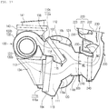
- FIG. 12 is a sectional view showing an air conditioning system according to another embodiment of the present invention. In comparison with the previous embodiment of the present invention, just different parts of this embodiment will be described.
- the air conditioning system has an air mixing part MC, which is formed inside the air-conditioning case 110 to be located at the front end of the through hole part 310 of the dash panel 300, such that cold air passing through the cold air passageway 111 and warm air passing through the warm air passageway 112 are mixed together.
- the air mixing part MC is formed at the outlet 110b of the air-conditioning case 110 where the cold air passageway 111 and the warm air passageway 112 meet together.
- the air conditioning system can secure a sufficient mixing performance because the cold air and the warm air are mixed from the front end of the through hole part 310 of the dash panel 300, namely, at the side of the engine room.
- the electric heater 240 is mounted inside the distribution duct 200 arranged in the interior of the vehicle.
- the electric heater 240 is selectively operated, for instance, may be operated only when heating performance is poor.
- the distribution duct 200 includes: a bypass passageway 245 formed such that the air flowing inside the distribution duct 200 bypasses the electric heater 240; and a bypass door 246 for controlling the degree of opening of the bypass passageway 245 and a passageway of the side of the electric heater 240.
- the air conditioning system can reduce a flow resistance of air.
Abstract
Description
- The present invention relates to an air conditioning system for a vehicle and, more particularly, to an air conditioning system for a vehicle in which an air-conditioning module having an air-conditioning case and a blower unit is disposed at a side of an engine room relative to a dash panel, and a distribution duct having a defrost vent, a face vent, and a floor vent is disposed in the interior of a vehicle relative to the dash panel so as to distribute cold air and hot air discharged from the air-conditioning case into the interior of the vehicle, wherein the floor vent is placed on one side of an area, in which a relatively large amount of hot air flows, in a mixing chamber of the distribution duct where cold air and hot air are mixed, i.e. a side adjacent to the dash panel.
- In general, as shown in
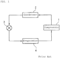
FIG. 1 , an air conditioning system for a vehicle has a refrigeration cycle that includes: acompressor 1 for compressing and discharging refrigerant; acondenser 2 for condensing the refrigerant of high pressure discharged from thecompressor 1; anexpansion valve 3 for throttling the refrigerant condensed and liquefied in thecondenser 2; and anevaporator 4 for exchanging heat between the liquefied refrigerant of low pressure throttled by theexpansion valve 3 and air blown to the interior of the vehicle and for evaporating the refrigerant to cool the air discharged to the interior of the vehicle through heat absorption by evaporative latent heat, and that thecompressor 1, thecondenser 2, theexpansion valve 3 and theevaporator 4 are connected with one another via refrigeration pipes. The air conditioning system cools the interior of the vehicle through the following refrigerant circulation process. - When a cooling switch (not shown) of the air conditioning system is turned on, first, the
compressor 1 inhales and compresses vapor-phase refrigerant of low-temperature and low-pressure while driving by driving power of an engine or a motor, and then sends the refrigerant in the gaseous phase of high-temperature and high-pressure to thecondenser 2. Then, thecondenser 2 condenses the vapor-phase refrigerant into liquid-phase refrigerant of high-temperature and high-pressure by exchanging heat with outdoor air. After that, the liquid-phase refrigerant of high-temperature and high-pressure sent from thecondenser 2 rapidly expands by a throttling action of theexpansion valve 3 and is sent to theevaporator 4 in a wet-saturated state of low-temperature and low-pressure. Theevaporator 4 exchanges heat between the refrigerant and air blown to the interior of the vehicle by a blower (not shown). Then, the refrigerant is evaporated in theevaporator 4 and discharged in a gaseous phase of low-temperature and low-pressure. After that, the vapor-phase refrigerant is inhaled into thecompressor 1, and then, recirculates the refrigeration cycle as described above. - The evaporator is mounted inside the air-conditioning case mounted to the interior of the vehicle to cool the interior of the vehicle. That is, the air blown by the blower (not shown) is cooled by evaporative latent heat of the liquid-phase refrigerant circulating inside the
evaporator 4 and discharged to the interior of the vehicle in a cooled state so as to cool the interior of the vehicle. - Moreover, the interior of the vehicle is heated by a heater core (not shown), which is mounted inside the air-conditioning case, and, through which coolant of the engine circulates, or by an electric heater (not shown) mounted inside the air-conditioning case. In the meantime, the
condenser 2 is mounted at the front side of the vehicle to radiate heat while exchanging heat with air. - Recently, an air conditioning system which carries out heating and cooling only using a refrigeration cycle has been developed. As shown in
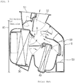
FIG. 2 , such an air conditioning system includes: acold air passageway 11 and awarm air passageway 12 which are partitioned to the right and the left inside one air-conditioning case 10; anevaporator 4 mounted on thecold air passageway 11 for cooling; and acondenser 2 mounted on thewarm air passageway 12 for heating. - In this instance, at an outlet of the air-
conditioning case 10, formed are a plurality ofair outflow ports 15 for supplying air to the interior of the vehicle and a plurality ofair discharge ports 16 for discharging air to the exterior of the vehicle. Furthermore,blowers 20 which are operated individually are respectively mounted at an inlet of thecold air passageway 11 and at an inlet of thewarm air passageway 12. The air-conditioning case 10 and theblowers 20 in the air conditioning system are mounted inside the interior of the vehicle based on a dash panel (not shown), which partitions an engine room from the interior of the vehicle. - Therefore, in a cooling mode, cold air cooled while passing through the
evaporator 4 of thecold air passageway 11 is discharged to the interior of the vehicle through theair outflow port 15 to cool the interior of the vehicle, and in this instance, warm air heated while passing through thecondenser 2 of thewarm air passageway 12 is discharged to the exterior of the vehicle through theair discharge port 16. - In a heating mode, warm air heated while passing through the
condenser 2 of thewarm air passageway 12 is discharged to the interior of the vehicle through theair outflow port 15 to heat the interior of the vehicle, and in this instance, cold air cooled while passing through theevaporator 4 of thecold air passageway 11 is discharged to the exterior of the vehicle through theair discharge port 16. - However, the conventional air conditioning system has a disadvantage in that it is difficult to secure an interior space of the vehicle because the air-
conditioning case 10, which has theevaporator 4 and thecondenser 2 mounted therein, and the blower (20) are mounted in the interior of the vehicle relative to the dash panel. -
FIG. 3 is a sectional view showing an example of the air-conditioning case mounted in the interior of the vehicle. Anevaporator 30 and aheater core 40 are mounted inside the air-conditioning case 10, and adefrost vent 51, aface vent 52 and afloor vent 53 are formed to discharge air to the interior of the vehicle. - However, the conventional air-
conditioning case 10 has several disadvantages in that the air-conditioning case 10 arranged in the interior of the vehicle becomes larger in size because thefloor vent 53 is formed in the air-conditioning case 10 to be far from thedash panel 60, and in that it is difficult to secure the interior space of the vehicle. - Accordingly, the present invention has been made in an effort to solve the above-mentioned problems occurring in the prior arts, and it is an object of the present invention to provide an air conditioning system for a vehicle, in which an air-conditioning module having an air-conditioning case and a blower unit is disposed at a side of an engine room relative to a dash panel, and a distribution duct having a defrost vent, a face vent, and a floor vent is disposed in the interior of a vehicle relative to the dash panel so as to distribute cold air and hot air discharged from the air-conditioning case into the interior of the vehicle, wherein the floor vent is placed on one side of an area, in which a relatively large amount of hot air flows, in a mixing chamber of the distribution duct where cold air and hot air are mixed, i.e. a side adjacent to the dash panel, thereby improving comfortability of the interior of the vehicle by discharging warmer air through the floor vent and discharging colder air through the face vent, preventing a reversal phenomenon between high and low temperatures, and reducing the size of the distribution duct and maximizing the interior space of the vehicle due to a structure that only the distribution duct is arranged in the interior of the vehicle and an arrangement structure of the floor vent.
- To achieve the above objects, the present invention provides an air conditioning system for a vehicle including: an air-conditioning case having a cold air passageway and a warm air passageway; and a distribution duct, which is connected with an outlet of the air-conditioning case and includes a defrost vent, a face vent, and a floor vent disposed to distribute cold air and warm air discharged from the air-conditioning case to a specific position of the interior of the vehicle according to air discharge modes, wherein the floor vent is placed on one side of an area, in which a relatively large amount of hot air flows, in a mixing chamber of the distribution duct where cold air and hot air are mixed together.
- The air conditioning system for a vehicle according to an embodiment of the present invention is configured such that the air-conditioning module having the air-conditioning case and the blower unit is disposed at a side of the engine room relative to the dash panel and the distribution duct having the defrost vent, the face vent, and the floor vent for distributing cold air and hot air discharged from the air-conditioning case into the interior of the vehicle is disposed in the interior of a vehicle relative to the dash panel, wherein the floor vent is placed on one side of an area, in which a relatively large amount of hot air flows, in a mixing chamber of the distribution duct where cold air and hot air are mixed, i.e. a side adjacent to the dash panel. Therefore, the air conditioning system according to the embodiment of the present invention can improve comfortability of the interior of the vehicle by discharging warmer air through the floor vent and discharging colder air through the face vent and prevent the reversal phenomenon between high and low temperatures
- Additionally, the air conditioning system according to the embodiment of the present invention can reduce the size of the distribution duct and maximize the interior space of the vehicle due to a structure that only the distribution duct is arranged in the interior of the vehicle and an arrangement structure of the floor vent.
-
-
FIG. 1 is a schematic diagram showing a refrigeration cycle of a general air conditioning system for a vehicle. -
FIG. 2 is a view showing a conventional air conditioning system for a vehicle. -
FIG. 3 is a sectional view showing an example of a conventional air-conditioning case mounted in the interior of the vehicle. -
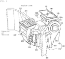
FIG. 4 is a perspective view showing an air conditioning system for a vehicle according to a preferred embodiment of the present invention. -
FIG. 5 is a perspective view showing a state where a distribution duct inFIG. 4 is separated. -
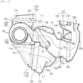
FIG. 6 is a perspective view showing an air-conditioning module of the air conditioning system for the vehicle according to the present invention. -
FIG. 7 is a perspective view viewed from an indoor air inflow duct ofFIG. 6 . -
FIG. 8 is a sectional view taken along the line A-A ofFIG. 7 . -
FIG. 9 is a sectional view showing a cooling mode of the air conditioning system for the vehicle according to the present invention. -
FIG. 10 is a sectional view showing a heating mode of the air conditioning system for the vehicle according to the present invention. -
FIG. 11 is a sectional view showing a mixing mode of the air conditioning system for the vehicle according to the present invention. -
FIG. 12 is a perspective view showing an air conditioning system for a vehicle according to another embodiment of the present invention. - Reference will be now made in detail to preferred embodiments of the present invention with reference to the attached drawings.
- As shown in the drawings, an air conditioning system for a vehicle according to the present invention includes a compressor (not shown), a
condenser 102, expansion means (not shown) and anevaporator 104, which are connected with one another in order through a refrigerant circulation line (not shown), so as to carry out cooling through theevaporator 104 and carry out heating through thecondenser 102. - First, the compressor inhales and compresses vapor-phase refrigerant of low-temperature and low-pressure discharged from the
evaporator 104 while operating by receiving a driving force from a power supply, such as an engine or a motor, and then, discharges the refrigerant in a vapor phase of high-temperature and high-pressure. - The
condenser 102 exchanges heat between the vapor-phase refrigerant of high-temperature and high-pressure, which is discharged from the compressor and flows inside thecondenser 102, and air passing through thecondenser 102, and in this instance, the refrigerant is condensed and the air is heated to be changed into warm air. - Such a
condenser 102 may have a structure that the refrigerant circulation line (refrigerant pipe) is arranged in the form of a zigzag and a radiation fin (not shown) is mounted or a structure that a plurality of tubes (not shown) are stacked up and a radiation fin is mounted between the tubes. - Therefore, the vapor-phase refrigerant of high-temperature and high-pressure discharged from the compressor exchanges heat with the air to be condensed while flowing along the zigzag-shaped refrigerant circulation line or the tubes, and in this instance, the air passing through the
condenser 102 is heated to be changed into warm air. - Moreover, the expansion means (not shown) rapidly expands liquid-phase refrigerant, which flows after being discharged from the
condenser 102, by throttling effect and sends the expanded refrigerant in a saturated state of low-temperature and low-pressure to theevaporator 104. The expansion means may be an expansion valve or an orifice structure. - The
evaporator 104 evaporates the liquid-phase refrigerant of low-pressure, which flows after being discharged from the expansion means, by exchanging heat between the liquid-phase refrigerant and the indoor air of the air-conditioning case 110 so as to cool the air due to a heat absorption by an evaporative latent heat of the refrigerant. Continuously, the vapor-phase refrigerant of low-temperature and low-pressure evaporated and discharged from theevaporator 104 is inhaled to thecompressor 100 again, and then, recirculates the above-mentioned cycle. - Furthermore, in the above-mentioned refrigerant circulation process, the air blown by a
blower unit 130 is introduced into the air-conditioning case 110, is cooled by the evaporative latent heat of the liquid-phase refrigerant circulating inside theevaporator 104, and then, is discharged to the interior of the vehicle in a cooled state through adistribution duct 200, so that the interior of the vehicle is heated. - The air blown by the
blower unit 130 is introduced into the air-conditioning case 110, is heated by heat radiation of the vapor-phase refrigerant of high-temperature and high-pressure circulating inside thecondenser 102 while passing through thecondenser 102, and then, is discharged to the interior of the vehicle in a heated state through thedistribution duct 200, so that the interior of the vehicle is cooled. - Additionally, the air conditioning system for the vehicle according to the present invention is configured by combination of the air-
conditioning module 100 and thedistribution duct 200. - The air-
conditioning module 100 includes: an air-conditioning case 110 having acold air passageway 111, on which theevaporator 104 is mounted, and awarm air passageway 112, on which thecondenser 102 is mounted; and theblower unit 130 for blowing air to thecold air passageway 111 and thewarm air passageway 112 of the air-conditioning case 110. - The
distribution duct 200 includesmode doors 230 which are connected with anoutlet 110b of the air-conditioning case 110 to distribute air discharged from the air-conditioning case 110 to a specific position of the interior of the vehicle according to air discharge modes. - Moreover, the air-
conditioning module 100 and thedistribution duct 200 are divided relative to adash panel 300 which partitions the interior of the vehicle from an engine room. That is, the air-conditioning module 100 is arranged at the engine room side relative to thedash panel 300 and thedistribution duct 200 is arranged at the interior side of the vehicle relative to thedash panel 300. - As described above, the air-
conditioning module 100 including the air-conditioning case 110, in which theevaporator 104 and thecondenser 102 are mounted, and theblower unit 130 is arranged at the engine room side relative to thedash panel 300, thedistribution duct 200 having themode doors 230 for distributing air to the interior of the vehicle is arranged at the interior side of the vehicle relative to thedash panel 300 to be combined with each other, so that the air conditioning system for the vehicle can reduce noise and vibration in the interior of the vehicle because the air-conditioning module 100, which causes noise, is arranged at the engine room side and can secure an interior space of the vehicle to the maximum compared with the existing air conditioning systems because just thedistribution duct 200 is arranged at the interior side of the vehicle. - In addition, the
dash panel 300 has a throughhole part 310, and as shown in the drawing, at least one throughhole part 310 may be formed. Moreover, as shown in the drawing, the throughhole part 310 may have a rectangular shape or one of various shapes. - Furthermore, the air-
conditioning module 100 arranged in the engine room and thedistribution duct 200 arranged at the interior of the vehicle are combined with each other through the throughhole part 310, namely, they are combined and connected with each other at the position of the throughhole part 310. - In other words, the
outlet 110b of the air-conditioning case 110 of the air-conditioning module 100 which penetrates through the throughhole part 310 of thedash panel 300 is combined with anair inflow port 210 of thedistribution duct 200, and in this instance, theair inflow port 210 of thedistribution duct 200 is inserted into theoutlet 110b of the air-conditioning case 110 to be combined. - Moreover, the cold and
warm air passageways conditioning case 110 are arranged to be respectively put at the upper part and the lower part inside the air-conditioning case 110, and adivision wall 113 is formed inside the air-conditioning case 110 to divide thecold air passageway 111 and thewarm air passageway 112 from each other. That is, the cold andwarm air passageways division wall 113, which divides the inside of the air-conditioning case 110 into the upper part and the lower part. - Here, the structure the cold and
warm air passageways cold air passageway 111 is arranged below thedivision wall 113, and thewarm air passageway 112 is arranged above thedivision wall 113. Of course, not shown in the drawings, but thecold air passageway 111 may be arranged above thedivision wall 113, and thewarm air passageway 112 may be arranged below thedivision wall 113. - In the meantime, the
cold air passageway 111 and thewarm air passageway 112 are formed in such a way as to be divided from each other at theinlet 110a of the air-conditioning case 110 by thedivision wall 113 and meet together at theoutlet 110b of the air-conditioning case 110. That is, because thedivision wall 113 is not formed at theoutlet 110b of the air-conditioning case 110, thecold air passageway 111 and thewarm air passageway 112 are joined together. - Moreover, the
evaporator 104 is mounted in thecold air passageway 111, and thecondenser 102 is mounted in thewarm air passageway 112. Additionally, due to the up-and-down arrangement structure of thewarm air passageway 112 and thecold air passageway 111, thecondenser 102 and theevaporator 104 are also arranged up and down. In other words, thecondenser 102 and theevaporator 104 are arranged at right angles to the axial direction that rotary shafts ofmotors second blowers - Meanwhile, cold air flows toward the
cold air passageway 111 in which theevaporator 104 is mounted, and warm air flows toward thewarm air passageway 112 in which thecondenser 102 is mounted. - Furthermore, a
bypass passageway 114 is formed to penetrate thedivision wall 113 formed between theevaporator 104 and thecondenser 102 to communicate thecold air passageway 111 and thewarm air passageway 112 with each other, and abypass door 115 is mounted on thebypass passageway 114 to open and close thebypass passageway 114. - The
bypass passageway 114 bypasses some of the cold air passing through theevaporator 104 inside thecold air passageway 111 toward thewarm air passageway 112, and thebypass door 115 closes thebypass passageway 114 in the cooling mode but selectively opens and closes thebypass passageway 114 in the heating mode. - Therefore, in a state where the
bypass door 115 closes thebypass passageway 114, in the cooling mode, the cold air cooled by the evaporator 1004 while flowing inside thecold air passageway 111 is supplied to the interior of the vehicle to carry out cooling, and the air flowing inside thewarm air passageway 112 is released out. In the heating mode, the warm air heated by thecondenser 102 while flowing inside thewarm air passageway 112 is supplied to the interior of the vehicle to carry out heating, and in this instance, the air flowing inside thecold air passageway 111 is released out. - Furthermore, when dehumidification is needed during the heating mode, the
bypass door 115 opens thebypass passageway 114. In this instance, some of the air cooled and dehumidified by theevaporator 104 while flowing inside thecold air passageway 111 is bypassed toward thewarm air passageway 112 through thebypass passageway 114, and then, is supplied to the interior of the vehicle to carry out dehumidification and heating. - Additionally, the
condenser 102 is mounted at the streamside lower than thebypass passageway 114. Therefore, the cold air heated while passing through theevaporator 104 can be supplied to thecondenser 102 through thebypass passageway 114. - In the meantime, the
evaporator 104 is mounted at the streamside higher than thebypass passageway 114 in an air flow direction inside thecold air passageway 111. - In addition, at one side of the
cold air passageway 111 of the air-conditioning case 110, disposed are a coldair discharge port 119a for discharging the cold air passing through theevaporator 104 to the outside and a coldair mode door 120 for opening and closing the coldair discharge port 119a and thecold air passageway 111. Moreover, at one side of thewarm air passageway 112 of the air-conditioning case 110, disposed are a warmair discharge port 119b for discharging the warm air passing through thecondenser 102 to the outside and a warmair mode door 121 for opening and closing the warmair discharge port 119b and thewarm air passageway 112. - The cold
air discharge port 119a and the coldair mode door 120 is disposed at the downstream side of theevaporator 104 in thecold air passageway 111, and the warmair discharge port 119b and the warmair mode door 121 is disposed at the downstream side of thecondenser 102 in thewarm air passageway 112. The air discharged through the coldair discharge port 119a and the warmair discharge port 119b is discharged to the outside of the vehicle through the engine room. - Therefore, in the cooling mode, the cold
air mode door 120 opens thecold air passageway 111 and the warmair mode door 121 opens the warmair discharge port 119b, so that the air flowing through thecold air passageway 111 is cooled while passing through theevaporator 104. After that, the cooled air is discharged to the interior of the vehicle through thedistribution duct 200 to cool the interior of the vehicle, and in this instance, the air flowing thewarm air passageway 112 is heated while passing through thecondenser 102, and then, is discharged to the outside through the warmair discharge port 119b. - In the heating mode, the warm
air mode door 121 opens thewarm air passageway 121 and the coldair mode door 120 opens the coldair discharge port 119a, so that the air flowing thewarm air passageway 112 is heated while passing through thecondenser 102. After that, the heated air is discharged to the interior of the vehicle through thedistribution duct 200, and in this instance, the air flowing thecold air passageway 111 is cooled while passing through theevaporator 104, and then, is discharged to the outside through the coldair discharge port 119a. Additionally, theair blower 130 is mounted at theinlet 110a of the air-conditioning case 110 to blow air toward thecold air passageway 111 and thewarm air passageway 112. - The
air blower 130 includes: afirst blower 130a for blowing air toward thecold air passageway 111 through adischarge port 134 connected to theinlet 111a of thecold air passageway 111 of the air-conditioning case 110; and asecond blower 130b for blowing air toward thewarm air passageway 112 through adischarge port 138 connected to theinlet 112a of thewarm air passageway 112 of the air-conditioning case 110. - The
first blower 130a and thesecond blower 130b are arranged to be spaced apart from each other and opposed to each other in the width direction of the vehicle. - The
first blower 130a includes: ascroll case 131 having thedischarge port 134 to be connected to theinlet 111a of thecold air passageway 111 of the air-conditioning case 110; ablast fan 132 rotatably mounted inside thescroll case 131; aninlet ring 131a which is formed on one side of thescroll case 131 to introduce indoor air and outdoor air; and amotor 133 which is mounted on the other side of thescroll case 131 to rotate theblast fan 132. - The
inlet ring 131a is formed on the one side of thescroll case 131 to which anintake duct 140 is located. - The
second blower 130b includes: ascroll case 135 having thedischarge port 138 to be connected to theinlet 112a of thewarm air passageway 112 of the air-conditioning case 110; ablast fan 136 rotatably mounted inside thescroll case 135; aninlet ring 135a which is formed on one side of thescroll case 135 to introduce indoor air and outdoor air; and amotor 137 which is mounted on the other side of thescroll case 135 to rotate theblast fan 136. - The
inlet ring 135a is formed on the one side of thescroll case 135 to which anintake duct 140 is located. Thefirst blower 130a and thesecond blower 130b are mounted in such a way that rotary shafts of themotors 133 and 1377 are in the same direction. Furthermore, theinlet ring 131a of thefirst blower 130a and theinlet ring 135a of thesecond blower 130b are formed to be opposed to each other. - Meanwhile, the
scroll cases second blowers blast fans blowers blast fans scroll cases - Moreover, the
discharge ports second blowers scroll cases cold air passageway 111 and thewarm air passageway 112. - In the meantime, the
scroll case 131 of thefirst blower 130a and thescroll case 135 of thesecond blower 130b are mounted to have scroll directions opposed to each other, such that thescroll case 131 of thefirst blower 130a is connected with thecold air passageway 111 located below thedivision wall 113 and thescroll case 135 of thesecond blower 130b is connected with thewarm air passageway 112 located above thedivision wall 113. - Furthermore, an
intake duct 140 which is connected with the first andsecond blowers first blower 130a and thesecond blower 130b so as to supply indoor air and outdoor air to the first andsecond blowers - That is, one
intake duct 140 is mounted between thefirst blower 130a and thesecond blower 130b, such that the first andsecond blowers intake duct 140. - As described above, because the
intake duct 140 is mounted between thefirst blower 130a and thesecond blower 130b, the system using the twoblowers intake duct 140 so as to maximize space efficiency and reduce the size and manufacturing costs of the system. - The
intake duct 140 includes: anoutdoor air inlet 141 for introducing outdoor air; anindoor air inlet 142 for introducing indoor air; a first indoor and outdoorair converting door 147 which is mounted to open and close a passageway for communicating theindoor air inlet 142, theoutdoor air inlet 141 and thefirst blower 130a to selectively introduce indoor air and outdoor air toward thefirst blower 130a; and a second indoor and outdoorair converting door 148 which is mounted to open and close a passageway for communicating theindoor air inlet 142, theoutdoor air inlet 141 and thesecond blower 130b to selectively introduce indoor air and outdoor air toward thesecond blower 130b. - In other words, the first indoor and outdoor
air converting door 147 is mounted at the upstream side of theinlet ring 131a of thefirst blower 130a between theoutdoor air inlet 141 and theindoor air inlet 142 in order to selectively open and close a passageway for communicating theinlet ring 131a and theoutdoor air inlet 141 with each other and a passageway for communicating theinlet ring 131a and theindoor air inlet 142 with each other. - The second indoor and outdoor
air converting door 148 is mounted at the upstream side of theinlet ring 135a of thesecond blower 130b between theoutdoor air inlet 141 and theindoor air inlet 142 in order to selectively open and close a passageway for communicating theinlet ring 135a and theoutdoor air inlet 141 with each other and a passageway for communicating theinlet ring 135a and theindoor air inlet 142 with each other. - Meanwhile, it is preferable that the
outdoor air inlet 141 be formed at an upper part of theintake duct 140 and theindoor air inlet 142 be formed at a lower part of theintake duct 140, but positions of theoutdoor air inlet 141 and theindoor air inlet 142 may be varied. The first indoor and outdoorair converting door 147 and the second indoor and outdoorair converting door 148 are dome-shaped doors. - As described above, one
intake duct 140 is mounted between thefirst blower 130a andsecond blower 130b and the first and second indoor and outdoorair converting doors intake duct 140, such that indoor air and outdoor air introduced into theindoor air inlet 142 and theoutdoor air inlet 141 of theintake duct 140 can be selectively supplied to the first andsecond blowers - In the meantime, air filters (not shown) are respectively mounted on the
outdoor air inlet 141 and theindoor air inlet 142 so as to remove impurities contained in the air introduced into theoutdoor air inlet 141 and theindoor air inlet 142. - Furthermore, the
outdoor air inlet 141 of theintake duct 140 communicates with the outside of the vehicle, and theindoor air inlet 142 of theintake duct 140 communicates with the interior of the vehicle. In this instance, an indoorair inflow duct 143 which connects theindoor air inlet 142 of theblower unit 130 with the interior of the vehicle is mounted on the outer face of the air-conditioning case 110. - That is, the indoor
air inflow duct 143 is mounted on the outer face of the air-conditioning case 110 to connect theindoor air inlet 142 of theintake duct 140 with the interior of the vehicle, and in this instance, aninlet 143a of the indoorair inflow duct 143 penetrates through thedash panel 300 and is connected with the interior of the vehicle. In this instance, theoutlet 110b of the air-conditioning case 110 and theinlet 143a of the indoorair inflow duct 143 are arranged side by side to penetrate the throughhole part 310. - The
inlet 143a of the indoorair inflow duct 143 and theoutlet 110b of the air-conditioning case 110 are arranged side by side to penetrate through the throughhole part 310, such that just one throughhole part 310 is formed in thedash panel 300 for installation of the air conditioning system. - Moreover, the
distribution duct 200 includes anair inflow port 210 connected with theoutlet 110b of the air-conditioning case 110, a plurality ofair outflow ports 220 for distributing air introduced into theair inflow port 210 to specific positions of the interior of the vehicle, and themode doors 230 for controlling the degree of opening of theair outflow ports 220. - The
air outflow ports 220 are adefrost vent 221 and aface vent 222 which are partitioned from each other at an upper part of thedistribution duct 200, and afloor vent 223 which is formed to be adjacent to thedash panel 300. - In this instance, for a passenger's comfort in the interior of the vehicle, the
floor vent 223 discharges air which is warmer than that of theface vent 222, and theface vent 222 or thedefrost vent 221 discharges air which is colder than that of thefloor vent 223. Because warm air flows above thedivision wall 113 and cold air flows below thedivision wall 113 inside the air-conditioning case 110, if the floor vent is arranged in the air-conditioning case to be far from the dash panel as shown inFIG. 3 , the cold air passing through theevaporator 104 is mostly discharged toward the floor vent, and the warm air passing throughcondenser 102 is mostly discharged toward the face vent so as to cause a reversal phenomenon between high and low temperatures. - Therefore, in the present invention, the
floor vent 223 is formed at one side of an area where relatively lots of warm air flows in a mixing chamber MC, in which cold air and warm air in thedistribution duct 200 are mixed together. - That is, warm air is introduced to the upper part and cold air is introduced to the lower part through the
air inflow port 210 of thedistribution duct 200, and then, the introduced cold air and warm air are mixed together in the mixing chamber MC of thedistribution duct 200. However, still, relatively lots of warm air flows to an upper zone and relatively lots of cold air flows to a lower zone in the mixing chamber MC. - Therefore, the
floor vent 223 is formed at one side of the area, in which a relatively large amount of hot air flows, out of the mixing chamber MC of thedistribution duct 200, i.e., a side adjacent to the dash panel in thedistribution duct 200, such that warmer air is discharged through thefloor vent 223 and colder air is discharged through theface vent 222 to enhance comfortability in the interior of the vehicle and prevent the reversal phenomenon between high and low temperatures. - Referring to
FIG. 11 , the warm air flowing along thewarm air passageway 112 disposed at the upper part inside the air-conditioning case 110 and the cold air flowing along thecold air passageway 111 disposed at the lower part inside the air-conditioning case 110 are introduced into thedistribution duct 200, and then, are mixed together in the mixing chamber MC. However, considering the flow of air, warmer air is discharged through thefloor vent 223, which is near to the area where the relatively large amount of warm air flows, and colder air is discharged through theface vent 222, which is near to the area where the relative large amount of cold air flows. - Meanwhile, the
floor vent 223 is formed at the position corresponding to thewarm air passageway 112, namely, is formed at the side of thedistribution duct 200 located at the position corresponding to thewarm air passageway 112. - Furthermore, the
floor vent 223, which is formed adjacent to thedash panel 300 in thedistribution duct 200, is formed between theair inflow port 210 and thedefrost vent 221 of thedistribution duct 200. - In the meantime, a
shower duct 250 is connected with thefloor vent 223 and is mounted on the outer surface of thedistribution duct 200 to guide the air discharged through thefloor vent 223 to the passenger's feet. - As described above, the air conditioning system according to the present invention can reduce the size of the
distribution duct 200 and secure the maximized space of the interior of the vehicle because only thedistribution duct 200 is arranged in the interior of the vehicle relative to thedash panel 300 and due to the arrangement structure of thefloor vent 223. - Meanwhile, the
defrost vent 221 discharges air toward the front window of the interior of the vehicle, theface vent 222 discharges air toward the face of the passenger who is sitting on the front seat of the vehicle, and thefloor vent 223 discharges air toward the passenger's feet. - Furthermore, the
mode doors 230 mounted in thedistribution duct 200 are respectively mounted at thedefrost vent 221, theface vent 222 and thefloor vent 223 to control the degrees of opening of the vents according to the air discharge modes. In this instance, themode door 230 for opening and closing thefloor vent 223 is a dome-shaped door and is mounted to face thedash panel 300. Of course, themode door 230 may adopt one of other doors of various types. Meanwhile, anelectric heater 240 may be mounted inside thedistribution duct 200. - Hereinafter, a refrigerant flowing process of the air conditioning system for the vehicle according to the present invention will be described.
- First, the vapor-phase refrigerant of high-temperature and high-pressure discharged after being compressed in the compressor is introduced into the
condenser 102. The vapor-phase refrigerant introduced into thecondenser 102 exchanges heat with the air passing through thecondenser 102, and in the above process, the refrigerant is liquefied while being cooled. The liquid-phase refrigerant discharged from thecondenser 102 is introduced into the expansion means to be decompressed and expanded. - The refrigerant decompressed and expanded in the expansion means becomes an atomized state of low-temperature and low-pressure and is introduced into the
evaporator 104. The refrigerant introduced into theevaporator 104 exchanges heat with the air passing through theevaporator 104 to be evaporated. After that, the refrigerant of low-temperature and low-pressure discharged from theevaporator 104 is introduced into the compressor, and then, recirculates the above-mentioned refrigeration cycle. - Hereinafter, air flow processes in the cooling mode, in the heating mode and in the mixing mode will be described.
- In the cooling mode, as shown in
FIG. 9 , the coldair mode door 120 is operated to open thecold air passageway 111, and the warmair mode door 121 is operated to open the warmair discharge port 119b. Additionally, the first and second indoor and outdoorair converting doors second blowers - Therefore, when the first and
second blowers intake duct 140 is inhaled to thefirst blower 130a and is supplied to thecold air passageway 111, and the outdoor air introduced into theintake duct 140 is inhaled to thesecond blower 130b and is supplied to thewarm air passageway 112. - The air supplied to the
cold air passageway 111 is cooled while passing through theevaporator 104, and then, flows to thedistribution duct 200. After that, the air is discharged to the interior of the vehicle through theair outflow port 220 by themode door 230 according to the air discharge mode in order to carry out cooling. In this instance, the air supplied to thewarm air passageway 112 is heated while passing through thecondenser 102, and then, is discharged to the exterior of the vehicle. - In the heating mode, as shown in
FIG. 10 , the warmair mode door 121 is operated to open thewarm air passageway 112, and the coldair mode door 120 is operated to open the coldair discharge port 119a. Additionally, the first and second indoor and outdoorair converting doors second blowers - Therefore, when the first and
second blowers intake duct 140 is inhaled to thefirst blower 130a and is supplied to thecold air passageway 111, and the outdoor air introduced into theintake duct 140 is inhaled to thesecond blower 130b and is supplied to thewarm air passageway 112. - The air supplied to the
warm air passageway 112 is heated while passing through thecondenser 102, and then, flows to thedistribution duct 200. After that, the air is discharged to the interior of the vehicle through theair outflow port 220 by themode door 230 according to the air discharge mode in order to carry out heating. In this instance, the air supplied to thecold air passageway 111 is cooled while passing through theevaporator 104, and then, is discharged to the exterior of the vehicle through the coldair discharge port 119a. - In the mixing mode, as shown in
FIG. 11 , the coldair mode door 120 is operated to open thecold air passageway 111, and the warmair mode door 121 is operated to open thewarm air passageway 112. Additionally, the first and second indoor and outdoorair converting doors second blowers - Therefore, when the first and
second blowers intake duct 140 is inhaled to thefirst blower 130a and is supplied to thecold air passageway 111, and the outdoor air introduced into theintake duct 140 is inhaled to thesecond blower 130b and is supplied to thewarm air passageway 112. - The air supplied to the
cold air passageway 111 is cooled while passing through theevaporator 104, and then, flows to thedistribution duct 200. The air supplied to thewarm air passageway 112 is heated while passing through thecondenser 102, and flows to thedistribution duct 200. Continuously, the cold air and the warm air flowing to thedistribution duct 200 are mixed together in the mixing chamber MC, and then, are discharged to the interior of the vehicle through theair outflow port 220 opened by themode door 230 according to the air discharge mode. - As shown in the drawings, after the cold air and the warm air are mixed together in the mixing chamber MC, the relatively large amount of the warm air is discharged through the
floor vent 223 and the relatively large amount of the cold air is discharged through theface vent 222. - In the meantime,
FIG. 12 is a sectional view showing an air conditioning system according to another embodiment of the present invention. In comparison with the previous embodiment of the present invention, just different parts of this embodiment will be described. - Referring to
FIG. 12 , the air conditioning system according to this embodiment has an air mixing part MC, which is formed inside the air-conditioning case 110 to be located at the front end of the throughhole part 310 of thedash panel 300, such that cold air passing through thecold air passageway 111 and warm air passing through thewarm air passageway 112 are mixed together. The air mixing part MC is formed at theoutlet 110b of the air-conditioning case 110 where thecold air passageway 111 and thewarm air passageway 112 meet together. - As described above, the air conditioning system can secure a sufficient mixing performance because the cold air and the warm air are mixed from the front end of the through
hole part 310 of thedash panel 300, namely, at the side of the engine room. - Moreover, the
electric heater 240 is mounted inside thedistribution duct 200 arranged in the interior of the vehicle. Theelectric heater 240 is selectively operated, for instance, may be operated only when heating performance is poor. - Furthermore, the
distribution duct 200 includes: abypass passageway 245 formed such that the air flowing inside thedistribution duct 200 bypasses theelectric heater 240; and abypass door 246 for controlling the degree of opening of thebypass passageway 245 and a passageway of the side of theelectric heater 240. - Therefore, when the
electric heater 240 is operated, as shown inFIG. 12 , thebypass passageway 245 is closed by thebypass door 246 such that the air passes through theelectric heater 246. When theelectric heater 240 is not operated, the passageway of the side of theelectric heater 240 is closed by thebypass door 246 such that the air bypasses theelectric heater 246. So, the air conditioning system can reduce a flow resistance of air.
Claims (18)
- An air conditioning system for a vehicle comprising:an air-conditioning case (110) having a cold air passageway (111) and a warm air passageway (112); anda distribution duct (200), which is connected with an outlet (110b) of the air-conditioning case (110) and includes a defrost vent (221), a face vent (222), and a floor vent (223) disposed to distribute cold air and warm air discharged from the air-conditioning case (110) to a specific position of the interior of the vehicle according to air discharge modes,wherein the floor vent (223) is placed on one side of an area, in which a relatively large amount of hot air flows, in a mixing chamber (MC) of the distribution duct (200) where cold air and hot air are mixed.
- The air conditioning system according to claim 1, wherein the air-conditioning case (110) is arranged at the side of an engine room relative to a dash panel (300), which partitions the engine room from the interior of the vehicle, and the distribution duct (200) is arranged in the interior of the vehicle.
- The air conditioning system according to claim 2, wherein the floor vent (223) is formed adjacent to the dash panel (300) in the distribution duct (200).
- The air conditioning system according to claim 3, wherein the defrost vent (221) and the face vent (222) are partitioned from each other at an upper part of the distribution duct (200), and
wherein the floor vent (223) is formed between an air inflow port (210) of the distribution duct (200) and the defrost vent (221). - The air conditioning system according to claim 1, wherein the cold and warm air passageways (111, 112) are arranged to be respectively put at an upper part and a lower part inside the air-conditioning case (110), and
wherein a division wall (113) is formed inside the air-conditioning case (110) to divide the cold air passageway (111) and the warm air passageway (112) from each other. - The air conditioning system according to claim 2, wherein a through hole part (310) is formed in the dash panel (300), and the air-conditioning case (110) and the distribution duct (200) are combined with each other through the through hole part (310).
- The air conditioning system according to claim 1, wherein an evaporator (104) is mounted in the cold air passageway (111) and a condenser (102) is mounted in the warm air passageway (112).
- The air conditioning system according to claim 7, wherein a cold air discharge port (119a) for discharging cold air passing through the evaporator (104) to the outside and a cold air mode door (120) for opening and closing the cold air discharge port (119a) and the cold air passageway (111) are disposed at one side of the cold air passageway (111) of the air-conditioning case (110), and
wherein a warm air discharge port (119b) for discharging warm air passing through the condenser (102) to the outside and a warm air mode door (121) for opening and closing the warm air discharge port (119b) and the warm air passageway (112) are disposed at one side of the warm air passageway (112) of the air-conditioning case (110. - The air conditioning system according to claim 1, wherein a blower unit (130) for blowing air to the cold air passageway (111) and the warm air passageway (112) is connected to the air-conditioning case (110).
- The air conditioning system according to claim 9, wherein the blower unit (130) comprises:a first blower (130a) connected to the side of an inlet (111a) of the cold air passageway (111) of the air-conditioning case (110) to blow air toward the cold air passageway (111); anda second blower (130b) connected to the side of an inlet (112a) of the warm air passageway (112) of the air-conditioning case (110) to blow air toward the warm air passageway (112).
- The air conditioning system according to claim 10, wherein the first blower (130a) and the second blower (130b) are arranged in the width direction of the vehicle, and
wherein an intake duct (140) for supplying indoor air and outdoor air to the first blower (130a) and the second blower (130b) is communicatingly mounted between the first blower (130a) and the second blower (130b) such that the first blower (130a) and the second blower (130b) use the intake duct (140) commonly. - The air conditioning system according to claim 5, wherein the floor vent (223) is located to correspond to the warm air passageway (112).
- The air conditioning system according to claim 3, wherein a mode door (230) for opening and closing the floor vent (223) is mounted in the distribution duct (200), and is mounted to face the dash panel (300).
- The air conditioning system according to claim 1, wherein the floor vent (223) is formed at the side of the distribution duct (200).
- The air conditioning system according to claim 2, wherein the cold air passageway (111) and the warm air passageway (112) are partitioned at an inlet (110a) of the air-conditioning case (110) from each other and meet together at an outlet (110b) of the air-conditioning case (110).
- The air conditioning system according to claim 15, wherein an electric heater (240) is mounted inside the distribution duct (200) arranged in the interior of the vehicle.
- The air conditioning system according to claim 16, wherein the distribution duct (200) comprises: a bypass passageway (245) formed such that the air flowing inside the distribution duct (200) bypasses the electric heater (240); and a bypass door (246) for controlling the degree of opening of the bypass passageway (245) and a passageway of the side of the electric heater (240).
- The air conditioning system according to claim 15, wherein a through hole part (310) is formed in the dash panel (300), and the air-conditioning module (100) and the distribution duct (200) are combined with each other through the through hole part (310), and
wherein an air mixing part (MC) where cold air passing through the cold air passageway (111) and warm air passing through the warm air passageway (112) are mixed together is formed inside the air-conditioning case (110) to be located at the front end of the through hole part (310).
Applications Claiming Priority (3)
| Application Number | Priority Date | Filing Date | Title |
|---|---|---|---|
| KR1020160005796A KR20170086724A (en) | 2016-01-18 | 2016-01-18 | Air conditining system for vehicle |
| KR1020160005777A KR102456814B1 (en) | 2016-01-18 | 2016-01-18 | Air conditioning system for vehicle |
| PCT/KR2017/000203 WO2017126833A2 (en) | 2016-01-18 | 2017-01-06 | Vehicle air-conditioning system |
Publications (3)
| Publication Number | Publication Date |
|---|---|
| EP3406469A2 true EP3406469A2 (en) | 2018-11-28 |
| EP3406469A4 EP3406469A4 (en) | 2020-01-08 |
| EP3406469B1 EP3406469B1 (en) | 2023-06-28 |
Family
ID=59361969
Family Applications (1)
| Application Number | Title | Priority Date | Filing Date |
|---|---|---|---|
| EP17741599.9A Active EP3406469B1 (en) | 2016-01-18 | 2017-01-06 | Vehicle air-conditioning system |
Country Status (5)
| Country | Link |
|---|---|
| US (1) | US11052726B2 (en) |
| EP (1) | EP3406469B1 (en) |
| JP (1) | JP6592535B2 (en) |
| CN (1) | CN107848372B (en) |
| WO (1) | WO2017126833A2 (en) |
Families Citing this family (10)
| Publication number | Priority date | Publication date | Assignee | Title |
|---|---|---|---|---|
| JP6592466B2 (en) * | 2016-01-18 | 2019-10-16 | ハンオン システムズ | Air conditioning system for vehicles |
| KR102456849B1 (en) * | 2017-12-15 | 2022-10-21 | 한온시스템 주식회사 | Air conditioner for vehicles |
| DE102018005338A1 (en) | 2018-07-06 | 2020-01-09 | Truma Gerätetechnik GmbH & Co. KG | air conditioning |
| FR3085622B1 (en) * | 2018-09-07 | 2020-08-07 | Valeo Systemes Thermiques | BOX FOR HEATING, VENTILATION AND / OR AIR CONDITIONING DEVICE OF A MOTOR VEHICLE |
| CN109515109A (en) * | 2018-10-25 | 2019-03-26 | 北京长城华冠汽车科技股份有限公司 | A kind of air-conditioning device and automobile of automobile |
| CN111156847A (en) * | 2018-11-07 | 2020-05-15 | 郑州尚格新能源有限公司 | Heat storage heating device and vehicle using same |
| JP7183804B2 (en) * | 2019-01-11 | 2022-12-06 | 株式会社デンソー | vehicle air conditioner |
| DE102019204717A1 (en) * | 2019-04-03 | 2020-10-08 | Mahle International Gmbh | Heating, ventilation or air conditioning |
| US20220402414A1 (en) * | 2019-12-20 | 2022-12-22 | Gentherm Incorporated | Air mixer for a vehicle seat |
| CA3179476A1 (en) * | 2020-05-18 | 2021-11-25 | Trane International Inc. | Hvac system for indoor agriculture |
Family Cites Families (27)
| Publication number | Priority date | Publication date | Assignee | Title |
|---|---|---|---|---|
| JPS6377809U (en) | 1986-11-11 | 1988-05-23 | ||
| JPH09132023A (en) * | 1995-11-09 | 1997-05-20 | Zexel Corp | Air conditioning unit |
| JP3982097B2 (en) * | 1998-11-11 | 2007-09-26 | 株式会社デンソー | Air conditioner for vehicles |
| JP2000326721A (en) | 1999-05-20 | 2000-11-28 | Mitsubishi Heavy Ind Ltd | Air conditioning unit and vehicular air conditioner |
| JPWO2001045973A1 (en) * | 1999-12-22 | 2004-01-08 | 株式会社ゼクセルヴァレオクライメートコントロール | Instrument panel module and air conditioner for automobile |
| JP4185649B2 (en) * | 2000-04-04 | 2008-11-26 | カルソニックカンセイ株式会社 | Air conditioning unit for automobile |
| JP2001287533A (en) * | 2000-04-07 | 2001-10-16 | Denso Corp | Vehicular air conditioner |
| DE10256619B3 (en) * | 2002-12-03 | 2004-01-22 | Iav Gmbh Ingenieurgesellschaft Auto Und Verkehr | Air conditioner for vehicles |
| JP3873925B2 (en) * | 2003-04-15 | 2007-01-31 | 株式会社デンソー | Air conditioner for vehicles |
| DE10335174A1 (en) * | 2003-07-30 | 2005-03-10 | Behr Gmbh & Co Kg | Air conditioning and its arrangement in a motor vehicle |
| ATE364516T1 (en) * | 2004-02-26 | 2007-07-15 | Behr France Rouffach Sas | CONSTRUCTION ARRANGEMENT FOR A HEAT EXCHANGE DEVICE |
| JP2006001378A (en) * | 2004-06-16 | 2006-01-05 | Denso Corp | Air conditioner for vehicle |
| JP2006007890A (en) | 2004-06-24 | 2006-01-12 | Zexel Valeo Climate Control Corp | Vehicular air conditioning unit |
| JP2006038309A (en) * | 2004-07-26 | 2006-02-09 | Tgk Co Ltd | Refrigerant relief device |
| JP4286244B2 (en) * | 2005-09-16 | 2009-06-24 | 株式会社ケーヒン | Air conditioner for vehicles |
| JP4375440B2 (en) * | 2007-05-30 | 2009-12-02 | 株式会社デンソー | Air conditioner for vehicles |
| KR101641148B1 (en) * | 2010-02-01 | 2016-07-20 | 한온시스템 주식회사 | Air conditioner for vehicle |
| JP5838316B2 (en) * | 2011-05-26 | 2016-01-06 | パナソニックIpマネジメント株式会社 | Air conditioner for vehicles |
| JP2013141933A (en) * | 2012-01-12 | 2013-07-22 | Panasonic Corp | Vehicle air conditioner |
| JP2013141930A (en) | 2012-01-12 | 2013-07-22 | Panasonic Corp | Vehicle air conditioner |
| JP2013141932A (en) | 2012-01-12 | 2013-07-22 | Panasonic Corp | Vehicle air conditioner |
| JP2013141931A (en) * | 2012-01-12 | 2013-07-22 | Panasonic Corp | Vehicle air conditioner |
| FR2991634B1 (en) * | 2012-06-08 | 2016-03-25 | Valeo Systemes Thermiques | THERMAL CONDITIONING SYSTEM FOR A CAR APARTMENT OF A VEHICLE, IN PARTICULAR AN ELECTRIC VEHICLE. |
| KR101998172B1 (en) * | 2012-08-29 | 2019-07-10 | 주식회사 두원공조 | Air conditioner for vehicle |
| KR101941052B1 (en) * | 2012-10-30 | 2019-01-24 | 한온시스템 주식회사 | Air conditioner for vehicle |
| JP6101065B2 (en) * | 2012-12-07 | 2017-03-22 | 株式会社日本クライメイトシステムズ | Air conditioner for vehicles |
| JP6111930B2 (en) * | 2013-08-20 | 2017-04-12 | 日産自動車株式会社 | Car fragrance device |
-
2017
- 2017-01-06 CN CN201780002269.5A patent/CN107848372B/en active Active
- 2017-01-06 WO PCT/KR2017/000203 patent/WO2017126833A2/en unknown
- 2017-01-06 EP EP17741599.9A patent/EP3406469B1/en active Active
- 2017-01-06 JP JP2017564686A patent/JP6592535B2/en active Active
- 2017-01-06 US US15/739,804 patent/US11052726B2/en active Active
Also Published As
| Publication number | Publication date |
|---|---|
| JP2018517612A (en) | 2018-07-05 |
| CN107848372B (en) | 2020-08-07 |
| CN107848372A (en) | 2018-03-27 |
| US20180361824A1 (en) | 2018-12-20 |
| EP3406469A4 (en) | 2020-01-08 |
| WO2017126833A3 (en) | 2017-09-08 |
| EP3406469B1 (en) | 2023-06-28 |
| WO2017126833A2 (en) | 2017-07-27 |
| US11052726B2 (en) | 2021-07-06 |
| JP6592535B2 (en) | 2019-10-16 |
Similar Documents
| Publication | Publication Date | Title |
|---|---|---|
| US10611207B2 (en) | Air conditioning system for vehicle | |
| US10479161B2 (en) | Vehicle air-conditioning system | |
| US11052726B2 (en) | Vehicle air-conditioning system | |
| US10457115B2 (en) | Air conditioning system for vehicle | |
| EP3623185B1 (en) | Heat pump system for vehicle | |
| KR102456818B1 (en) | Air conditioning system for vehicle | |
| KR20170086726A (en) | Air conditining system for vehicle | |
| KR20160027527A (en) | Heat pump system for vehicle | |
| KR102456822B1 (en) | Air conditioning system for vehicle | |
| KR20170086724A (en) | Air conditining system for vehicle | |
| KR20180011904A (en) | Air conditioning system for vehicle | |
| KR102456814B1 (en) | Air conditioning system for vehicle | |
| KR102552117B1 (en) | Air conditioning system for vehicle | |
| KR102536578B1 (en) | Air conditioning system for vehicle | |
| KR20170086727A (en) | Air conditining system for vehicle | |
| KR20160027526A (en) | Heat pump system for vehicle | |
| KR20180008977A (en) | Air conditining system for vehicle | |
| KR20170086722A (en) | Air conditining system for vehicle | |
| KR20180011902A (en) | Air conditioning system for vehicle |
Legal Events
| Date | Code | Title | Description |
|---|---|---|---|
| STAA | Information on the status of an ep patent application or granted ep patent |
Free format text: STATUS: THE INTERNATIONAL PUBLICATION HAS BEEN MADE |
|
| PUAI | Public reference made under article 153(3) epc to a published international application that has entered the european phase |
Free format text: ORIGINAL CODE: 0009012 |
|
| STAA | Information on the status of an ep patent application or granted ep patent |
Free format text: STATUS: REQUEST FOR EXAMINATION WAS MADE |
|
| 17P | Request for examination filed |
Effective date: 20171229 |
|
| AK | Designated contracting states |
Kind code of ref document: A2 Designated state(s): AL AT BE BG CH CY CZ DE DK EE ES FI FR GB GR HR HU IE IS IT LI LT LU LV MC MK MT NL NO PL PT RO RS SE SI SK SM TR |
|
| AX | Request for extension of the european patent |
Extension state: BA ME |
|
| DAV | Request for validation of the european patent (deleted) | ||
| DAX | Request for extension of the european patent (deleted) | ||
| A4 | Supplementary search report drawn up and despatched |
Effective date: 20191211 |
|
| RIC1 | Information provided on ipc code assigned before grant |
Ipc: B60H 1/00 20060101AFI20191205BHEP Ipc: B60H 1/32 20060101ALI20191205BHEP |
|
| STAA | Information on the status of an ep patent application or granted ep patent |
Free format text: STATUS: EXAMINATION IS IN PROGRESS |
|
| STAA | Information on the status of an ep patent application or granted ep patent |
Free format text: STATUS: EXAMINATION IS IN PROGRESS |
|
| 17Q | First examination report despatched |
Effective date: 20201127 |
|
| STAA | Information on the status of an ep patent application or granted ep patent |
Free format text: STATUS: EXAMINATION IS IN PROGRESS |
|
| GRAP | Despatch of communication of intention to grant a patent |
Free format text: ORIGINAL CODE: EPIDOSNIGR1 |
|
| STAA | Information on the status of an ep patent application or granted ep patent |
Free format text: STATUS: GRANT OF PATENT IS INTENDED |
|
| INTG | Intention to grant announced |
Effective date: 20230119 |
|
| GRAS | Grant fee paid |
Free format text: ORIGINAL CODE: EPIDOSNIGR3 |
|
| GRAA | (expected) grant |
Free format text: ORIGINAL CODE: 0009210 |
|
| STAA | Information on the status of an ep patent application or granted ep patent |
Free format text: STATUS: THE PATENT HAS BEEN GRANTED |
|
| RAP3 | Party data changed (applicant data changed or rights of an application transferred) |
Owner name: HANON SYSTEMS |
|
| AK | Designated contracting states |
Kind code of ref document: B1 Designated state(s): AL AT BE BG CH CY CZ DE DK EE ES FI FR GB GR HR HU IE IS IT LI LT LU LV MC MK MT NL NO PL PT RO RS SE SI SK SM TR |
|
| P01 | Opt-out of the competence of the unified patent court (upc) registered |
Effective date: 20230522 |
|
| REG | Reference to a national code |
Ref country code: CH Ref legal event code: EP |
|
| REG | Reference to a national code |
Ref country code: AT Ref legal event code: REF Ref document number: 1582411 Country of ref document: AT Kind code of ref document: T Effective date: 20230715 |
|
| REG | Reference to a national code |
Ref country code: IE Ref legal event code: FG4D |
|
| REG | Reference to a national code |
Ref country code: DE Ref legal event code: R096 Ref document number: 602017070659 Country of ref document: DE |
|
| REG | Reference to a national code |
Ref country code: LT Ref legal event code: MG9D |
|
| PG25 | Lapsed in a contracting state [announced via postgrant information from national office to epo] |
Ref country code: SE Free format text: LAPSE BECAUSE OF FAILURE TO SUBMIT A TRANSLATION OF THE DESCRIPTION OR TO PAY THE FEE WITHIN THE PRESCRIBED TIME-LIMIT Effective date: 20230628 Ref country code: NO Free format text: LAPSE BECAUSE OF FAILURE TO SUBMIT A TRANSLATION OF THE DESCRIPTION OR TO PAY THE FEE WITHIN THE PRESCRIBED TIME-LIMIT Effective date: 20230928 |
|
| REG | Reference to a national code |
Ref country code: NL Ref legal event code: MP Effective date: 20230628 |
|
| REG | Reference to a national code |
Ref country code: AT Ref legal event code: MK05 Ref document number: 1582411 Country of ref document: AT Kind code of ref document: T Effective date: 20230628 |
|
| PG25 | Lapsed in a contracting state [announced via postgrant information from national office to epo] |
Ref country code: RS Free format text: LAPSE BECAUSE OF FAILURE TO SUBMIT A TRANSLATION OF THE DESCRIPTION OR TO PAY THE FEE WITHIN THE PRESCRIBED TIME-LIMIT Effective date: 20230628 Ref country code: NL Free format text: LAPSE BECAUSE OF FAILURE TO SUBMIT A TRANSLATION OF THE DESCRIPTION OR TO PAY THE FEE WITHIN THE PRESCRIBED TIME-LIMIT Effective date: 20230628 Ref country code: LV Free format text: LAPSE BECAUSE OF FAILURE TO SUBMIT A TRANSLATION OF THE DESCRIPTION OR TO PAY THE FEE WITHIN THE PRESCRIBED TIME-LIMIT Effective date: 20230628 Ref country code: LT Free format text: LAPSE BECAUSE OF FAILURE TO SUBMIT A TRANSLATION OF THE DESCRIPTION OR TO PAY THE FEE WITHIN THE PRESCRIBED TIME-LIMIT Effective date: 20230628 Ref country code: HR Free format text: LAPSE BECAUSE OF FAILURE TO SUBMIT A TRANSLATION OF THE DESCRIPTION OR TO PAY THE FEE WITHIN THE PRESCRIBED TIME-LIMIT Effective date: 20230628 Ref country code: GR Free format text: LAPSE BECAUSE OF FAILURE TO SUBMIT A TRANSLATION OF THE DESCRIPTION OR TO PAY THE FEE WITHIN THE PRESCRIBED TIME-LIMIT Effective date: 20230929 |
|
| PG25 | Lapsed in a contracting state [announced via postgrant information from national office to epo] |
Ref country code: FI Free format text: LAPSE BECAUSE OF FAILURE TO SUBMIT A TRANSLATION OF THE DESCRIPTION OR TO PAY THE FEE WITHIN THE PRESCRIBED TIME-LIMIT Effective date: 20230628 |
|
| PG25 | Lapsed in a contracting state [announced via postgrant information from national office to epo] |
Ref country code: SK Free format text: LAPSE BECAUSE OF FAILURE TO SUBMIT A TRANSLATION OF THE DESCRIPTION OR TO PAY THE FEE WITHIN THE PRESCRIBED TIME-LIMIT Effective date: 20230628 |
|
| PG25 | Lapsed in a contracting state [announced via postgrant information from national office to epo] |
Ref country code: ES Free format text: LAPSE BECAUSE OF FAILURE TO SUBMIT A TRANSLATION OF THE DESCRIPTION OR TO PAY THE FEE WITHIN THE PRESCRIBED TIME-LIMIT Effective date: 20230628 |
|
| PG25 | Lapsed in a contracting state [announced via postgrant information from national office to epo] |
Ref country code: IS Free format text: LAPSE BECAUSE OF FAILURE TO SUBMIT A TRANSLATION OF THE DESCRIPTION OR TO PAY THE FEE WITHIN THE PRESCRIBED TIME-LIMIT Effective date: 20231028 |
|
| PG25 | Lapsed in a contracting state [announced via postgrant information from national office to epo] |
Ref country code: SM Free format text: LAPSE BECAUSE OF FAILURE TO SUBMIT A TRANSLATION OF THE DESCRIPTION OR TO PAY THE FEE WITHIN THE PRESCRIBED TIME-LIMIT Effective date: 20230628 Ref country code: SK Free format text: LAPSE BECAUSE OF FAILURE TO SUBMIT A TRANSLATION OF THE DESCRIPTION OR TO PAY THE FEE WITHIN THE PRESCRIBED TIME-LIMIT Effective date: 20230628 Ref country code: RO Free format text: LAPSE BECAUSE OF FAILURE TO SUBMIT A TRANSLATION OF THE DESCRIPTION OR TO PAY THE FEE WITHIN THE PRESCRIBED TIME-LIMIT Effective date: 20230628 Ref country code: PT Free format text: LAPSE BECAUSE OF FAILURE TO SUBMIT A TRANSLATION OF THE DESCRIPTION OR TO PAY THE FEE WITHIN THE PRESCRIBED TIME-LIMIT Effective date: 20231030 Ref country code: IS Free format text: LAPSE BECAUSE OF FAILURE TO SUBMIT A TRANSLATION OF THE DESCRIPTION OR TO PAY THE FEE WITHIN THE PRESCRIBED TIME-LIMIT Effective date: 20231028 Ref country code: ES Free format text: LAPSE BECAUSE OF FAILURE TO SUBMIT A TRANSLATION OF THE DESCRIPTION OR TO PAY THE FEE WITHIN THE PRESCRIBED TIME-LIMIT Effective date: 20230628 Ref country code: EE Free format text: LAPSE BECAUSE OF FAILURE TO SUBMIT A TRANSLATION OF THE DESCRIPTION OR TO PAY THE FEE WITHIN THE PRESCRIBED TIME-LIMIT Effective date: 20230628 Ref country code: CZ Free format text: LAPSE BECAUSE OF FAILURE TO SUBMIT A TRANSLATION OF THE DESCRIPTION OR TO PAY THE FEE WITHIN THE PRESCRIBED TIME-LIMIT Effective date: 20230628 Ref country code: AT Free format text: LAPSE BECAUSE OF FAILURE TO SUBMIT A TRANSLATION OF THE DESCRIPTION OR TO PAY THE FEE WITHIN THE PRESCRIBED TIME-LIMIT Effective date: 20230628 |
|
| PG25 | Lapsed in a contracting state [announced via postgrant information from national office to epo] |
Ref country code: PL Free format text: LAPSE BECAUSE OF FAILURE TO SUBMIT A TRANSLATION OF THE DESCRIPTION OR TO PAY THE FEE WITHIN THE PRESCRIBED TIME-LIMIT Effective date: 20230628 |