EP3406435A1 - Procédé et presse de compression d'une natte de matériau comprimable - Google Patents
Procédé et presse de compression d'une natte de matériau comprimable Download PDFInfo
- Publication number
- EP3406435A1 EP3406435A1 EP18163237.3A EP18163237A EP3406435A1 EP 3406435 A1 EP3406435 A1 EP 3406435A1 EP 18163237 A EP18163237 A EP 18163237A EP 3406435 A1 EP3406435 A1 EP 3406435A1
- Authority
- EP
- European Patent Office
- Prior art keywords
- press
- compression
- plate
- length
- pressing
- Prior art date
- Legal status (The legal status is an assumption and is not a legal conclusion. Google has not performed a legal analysis and makes no representation as to the accuracy of the status listed.)
- Granted
Links
- 239000000463 material Substances 0.000 title claims abstract description 42
- 238000003825 pressing Methods 0.000 title claims abstract description 41
- 238000000034 method Methods 0.000 title claims abstract description 32
- 230000006835 compression Effects 0.000 claims abstract description 92
- 238000007906 compression Methods 0.000 claims abstract description 92
- 239000002023 wood Substances 0.000 claims abstract description 10
- 238000004519 manufacturing process Methods 0.000 claims abstract description 8
- 238000009826 distribution Methods 0.000 claims description 7
- XLYOFNOQVPJJNP-UHFFFAOYSA-N water Substances O XLYOFNOQVPJJNP-UHFFFAOYSA-N 0.000 claims description 4
- 125000004122 cyclic group Chemical group 0.000 claims description 3
- 238000003892 spreading Methods 0.000 claims description 3
- 239000011094 fiberboard Substances 0.000 abstract description 4
- 238000011144 upstream manufacturing Methods 0.000 abstract 1
- 238000005056 compaction Methods 0.000 description 14
- 238000007596 consolidation process Methods 0.000 description 8
- 238000010276 construction Methods 0.000 description 7
- 238000005452 bending Methods 0.000 description 6
- 230000006837 decompression Effects 0.000 description 5
- 238000010438 heat treatment Methods 0.000 description 5
- 230000000694 effects Effects 0.000 description 3
- 239000003292 glue Substances 0.000 description 3
- 238000005096 rolling process Methods 0.000 description 3
- 229910000831 Steel Inorganic materials 0.000 description 2
- 239000011093 chipboard Substances 0.000 description 2
- 230000010349 pulsation Effects 0.000 description 2
- 239000010959 steel Substances 0.000 description 2
- 240000003085 Quassia amara Species 0.000 description 1
- 239000003921 oil Substances 0.000 description 1
- 239000000123 paper Substances 0.000 description 1
- 230000002035 prolonged effect Effects 0.000 description 1
- 230000035939 shock Effects 0.000 description 1
- 239000007921 spray Substances 0.000 description 1
- 238000005507 spraying Methods 0.000 description 1
- 238000005496 tempering Methods 0.000 description 1
- 238000013316 zoning Methods 0.000 description 1
Images
Classifications
-
- B—PERFORMING OPERATIONS; TRANSPORTING
- B30—PRESSES
- B30B—PRESSES IN GENERAL
- B30B5/00—Presses characterised by the use of pressing means other than those mentioned in the preceding groups
- B30B5/04—Presses characterised by the use of pressing means other than those mentioned in the preceding groups wherein the pressing means is in the form of an endless band
- B30B5/06—Presses characterised by the use of pressing means other than those mentioned in the preceding groups wherein the pressing means is in the form of an endless band co-operating with another endless band
-
- B—PERFORMING OPERATIONS; TRANSPORTING
- B27—WORKING OR PRESERVING WOOD OR SIMILAR MATERIAL; NAILING OR STAPLING MACHINES IN GENERAL
- B27N—MANUFACTURE BY DRY PROCESSES OF ARTICLES, WITH OR WITHOUT ORGANIC BINDING AGENTS, MADE FROM PARTICLES OR FIBRES CONSISTING OF WOOD OR OTHER LIGNOCELLULOSIC OR LIKE ORGANIC MATERIAL
- B27N3/00—Manufacture of substantially flat articles, e.g. boards, from particles or fibres
- B27N3/08—Moulding or pressing
- B27N3/24—Moulding or pressing characterised by using continuously acting presses having endless belts or chains moved within the compression zone
Definitions
- the invention relates to a method for pressing a pressed product mat in the course of the production of wood-based material, in particular fiberboard, chipboard or the like, in a continuous press, wherein the press comprises a press frame (eg with a plurality of press frames arranged one behind the other in the press longitudinal direction), at least one (heated / heated) upper press plate and at least one (heated / heated) lower press plate, wherein the upper press plate and / or the lower press plate for adjusting a arranged between the press plates press nip with z.
- a press frame eg with a plurality of press frames arranged one behind the other in the press longitudinal direction
- at least one (heated / heated) upper press plate and at least one (heated / heated) lower press plate wherein the upper press plate and / or the lower press plate for adjusting a arranged between the press plates press nip with z.
- a compression region of predetermined length is formed by the press plates on the inlet side, in which the press material mat entering the press nip is compressed during a compression phase to a degree of compaction which is up to 20% (preferably up to 15%) greater than the final dimension of the paper emerging from the press Plate is, wherein from the press plates adjoining the compression area main pressing area (for consolidation and / or calibration) of predetermined length is formed, in which the pressed material mat is only compacted from the compacting measure to the final dimension and consolidated and optionally calibrated.
- each endlessly circulating press belts z. B. steel bands provided with the interposition of WälzSystemaggregaten, z. B. Roll bars, to the Press plates are supported.
- the pressed material mat is guided with the help of press belts in the press nip and passed through the press nip at a feed rate and pressed using pressure and heat to a wood-based panel or a (continuous) wood-based panel strand.
- Wood material board means in particular fiberboard or chipboard. In a fiberboard, it may be z. B. to an MDF board or act on an HDF or LDF plate.
- the method consequently relates to the production of wood-based panels in a continuously operating press and in particular a double-belt press, which has flexible and consequently flexurally elastic press plates (eg inlet plates) at least in the inlet-side compression region, so that the inlet contour is stepless and infinitely variable at least in the inlet-side compression region can be practically set to produce any continuous bending lines.
- a double-belt press which has flexible and consequently flexurally elastic press plates (eg inlet plates) at least in the inlet-side compression region, so that the inlet contour is stepless and infinitely variable at least in the inlet-side compression region can be practically set to produce any continuous bending lines.
- Such a continuous press is z. B. from the DE 197 40 325 C5 known.
- the press on the inlet side bending elastic inlet plates, connected to which in several rows double-acting differential cylinder, so that tensile and compressive forces for setting continuous bending lines in a predetermined distribution to the upper inlet plate or to the lower inlet plate are connected.
- the support lines on the press plate of the fixed press frame to the support lines on the press plate of the movable press frame be offset from each other, so that in the main press area, both the upper press plate and the lower press plate parallel to each other wavy to form a over the press lengths be deformed constant press nip.
- the invention has for its object to provide a method for pressing a pressed material in the course of the production of wood-based panels in a continuous press of the type described above, which is characterized by particularly high efficiency with high board quality.
- the invention teaches in a generic method that the length of the compression region is more than 15%, preferably more than 25% of the total compression length of the press area and the press plates. This means that the length of the compression area is preferably more than 33% of the length of the main pressing area.
- the length of the compression region is particularly preferably more than 50% of the total length of the press (or the press plates) composed of the compression region and the main compression region. This means that in this particularly preferred embodiment, the length of the compression region is even greater than the length of the main pressing region.
- the invention is based on the surprising finding that the pressing process can be optimized, in particular with regard to cost-effectiveness, when working in the course of pressing with a significantly extended press inlet or a significantly extended compression zone, particularly preferably in conjunction with a significantly increased Feed rate, d. H. with a significantly increased speed of the rotating press belts, which define the speed of passage of the press mat by the continuous press.
- the feed rate of the pressed material mat can be increased and it has surprisingly been found that a very rapid heat input into the mat is achieved in this way and the respectively critical temperature (from eg 100 ° C.) to a much earlier one Time is reached, as in a conventional inlet construction or inlet adjustment with conventional feed rates.
- temperatures of the press plates compared to conventional modes significantly increase. It can, for. B. with temperatures of the press plates of more than 250 ° C, preferably more than 270 ° C, more preferably more than 300 ° C are worked. This is possible through the use of modern tempering media or thermal oils.
- the inventive method with a fast time compression in a spatially long compression area at the same time reduced Main press area can thus be realized in particular at high feed speeds and high temperatures with a high humidification, the z. B. at least 1% by weight, preferably at least 2% by weight, more preferably more than 3% by weight and in each case based on the weight of the still to be moistened grit mat.
- This moistening can be divided (for example, in half) on the top side and the underside of the spreading material mat. It is possible to spray the top and bottom with water.
- moistening the forming belt, on which the spreading material mat is applied In any case, the effects described can be optimized, in particular in connection with high speeds and high temperatures, with a high moistening of the mat.
- the invention is based on the recognition that the press can be driven at a particularly high speed when sufficiently high humidity is available to enhance the steam shock effect.
- This compression phase relates to that phase of the pressing process in which the pressed material mat is compressed, namely to a compacting dimension V which is only slightly larger than the final dimension N of the finished press plate or even substantially corresponds to the final dimension. It is customary in the compression of pressed material mats to compress the pressed material mat first in a compression phase to a compression ratio V, which is only slightly larger than the final dimension, z. B. up to 20% larger, preferably about 10% to 15% larger than the final size. This degree of compaction V is therefore also referred to in practice as "residual distance".
- the compression area thus ends where the Mat is compacted to this compaction level.
- the compression takes place at this residual distance in a relatively long inlet area and consequently compression area and then there is only a relatively short main press area, in which the final compression of residual distance to final gauge and the consolidation and optionally a calibration.
- the method according to the invention which is based on a significant lengthening of the inlet area or compression area, can basically be realized in that the press plates form a continuously tapered inlet mouth in this (long) compression area.
- the press nip thus continues to run continuously in this compression region (in a basically known manner).
- the pressing process can be accelerated.
- a pulsation in the compression area is generated selectively and actively and surprisingly, it has been found that a higher temperature in the mat can be achieved much faster if the pressed material mat in the inlet area cyclically compressed and decompressed, with a surprising effect in that a very rapid heat input into the mat succeeds and the respective critical temperature (of eg 100 ° C.) is reached even earlier in the press than with conventional inlet settings. Due to the pulsating compression and decompression, the steam can penetrate very quickly into the mat interior, so that a very rapid heating takes place.
- the upper press plate and / or the lower press plate is at least partially formed wave-like or adjusted so that the pressed material mat in the compression region in the working direction successively undergoes several pulsating compression phases.
- the inlet mouth is not opened and closed a total of pulsating, but a press plate is set with a waveform so that the continuous Pressgutmatte successively undergoes compression and decompression. Also in this way the heat input can be further accelerated.
- the inventive method can be realized with a continuous press, which corresponds in its basic structure to the previously known structure.
- a continuous press has a press frame, a heatable upper press plate in the press upper part and a heatable lower press plate in the press base, wherein the upper press plate and / or the lower press plate is acted upon by press brackets supported pressing cylinders.
- endless circulating pressing belts run around, which are supported on the press plates with the interposition of rolling element units.
- Such a press is also referred to as a double-belt press. It is now designed according to the invention configured so that the length of the compression region more than 15%, z. B.
- the infeed plates can then define the compaction area and the main press plates define the main crimp area.
- a continuous press in which a Split between bending elastic inlet plates on the one hand and relatively stiff main press plates on the other hand is dispensed with.
- the invention proposes in this (independent) aspect, that the upper press plate and / or the lower press plate is formed over its entire length as a flexible and thus flexurally elastic press plate or are formed.
- This can be z. B. realize that the thickness of the upper press plate and / or the thickness of the lower press plate less than 80 mm, more preferably less than 70 mm, z. B. is about 60 mm.
- the press plates are z. B. made of steel. They can be provided with heating channels for a heating medium.
- this press has relatively thin press plates over its entire length, which are designed as heating plates and consequently heatable press plates and which in this way allow the greatest possible flexibility over the entire press length.
- the inlet area is then no longer a structurally isolated area, but it is created by variable adjustment of the press plates (with continuous thickness), so that a universal usable continuous press is provided, in which - depending on the product and requirements - solely by the respective settings an inlet area or compression area of the desired length and geometry is provided.
- This compaction area is defined so that it means the area in which the pressed material mat is compressed to the compression ratio or the residual distance, so that then possibly still the residual compression of the residual distance to final gauge and a corresponding consolidation must be made.
- the required rigidity for the operation of different pressure zones should be achieved by correspondingly variable distances between the press frame and / or by the number of press cylinders in the press frame. It is provided in a particularly preferred embodiment that the press frame has a plurality of press frame in succession arranged press frame, wherein the press frame has over the entire length press frame with identical frame thickness.
- the press frame can be built from a variety of press frame identical frame thickness, which can be used in different areas of the press with multiple frame (eg double frame or triple frame), the be composed of two or more press frame of uniform frame thickness.
- press cylinders of identical design and possibly identical dimensions over the entire press length.
- the press is therefore preferably constructed with a single cylinder type (based on the press cylinders).
- a single cylinder type based on the press cylinders.
- the press cylinders are consequently arranged on the press frame and consequently on the frame level, while the return cylinders are preferably suspended between the press frame.
- the feed rate depends on the plate thickness to be produced.
- the feed rate may be more than 300 mm / s, preferably more than 400 mm / s, preferably at a press length of 20 m to 45 m, e.g. B. 30 m to 40 m. In the production of much thinner plates is then worked at significantly higher feed rates.
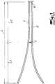
- the first aspect of the invention which relates particularly to the claimed method, is based on the Fig. 1 be explained.
- Shown are the upper press plate 1 and the lower press plate 2 of a continuous double belt press.
- a double belt press has an in Fig. 1 not shown press frame and a plurality of pressing cylinders, which in Fig. 1 also not shown and the z. B. act on the upper press plate.
- Such a press endlessly revolving pressing belts which are supported with the interposition of rolling rods on the press plates 1, 2.
- the press plates 1, 2 are heated, so that a press material mat passing through the press under application of pressure and heat to a plate, for. B. wood-based panel is pressed.
- press plates 1, 2 a compression region is formed on the inlet side, which has a length L1.
- the press material mat entering the press nip (between the press belts) in the working direction A is compressed during a compression phase to a compacting dimension V, which is also referred to as the residual distance.
- This degree of compaction is only up to 20%, preferably up to 15% greater than the final dimension N of the expiring from the press plate.
- the compression area consequently ends where this degree of compaction is achieved.
- the pressing plates form a main pressing area of length L2 adjoining the compacting area.
- the pressed material mat is then (only) rest compacted from the compacting dimension V to the final dimension N and the plate is consolidated and, if necessary, calibrated.
- the respective thickness of the pressed material mat refers to the press belts, not shown, between which the mat is arranged.
- the compression region occupies a very small part of the total length of the press or their press plates, it is now provided according to the invention that the length L1 of the compression region is more than 25% of the total length L, which is composed of the compression region and the main compression region , In the embodiment according to Fig. 1 the length L1 of the compression region is greater than the length L2 of the main compression region, ie the length L1 of the compression region is more than 50% of the total length L.
- This concept according to the invention can basically be realized by using flexible inlet plates and, for the main pressing region, relatively rigid main press plates in a known manner on the one hand for the compression region, so that work is then carried out with relatively long inlet plates.
- Fig. 1 a particularly preferred embodiment of the invention is shown, in which both the upper press plate 1 and the lower press plate 2 are formed over their entire length as flexible, flexurally elastic press plates 1, 2, which has a relatively small thickness of z. B. less than 70 mm.
- This embodiment has the advantage that the compression area on the one hand and the main press area on the other hand are not structurally determined, but can be flexibly adjusted and thus adapted to the particular circumstances. It is therefore possible to work in such a press with different compression ranges of greatly different lengths.
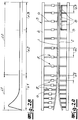
- FIG. 2a shows a continuously operating press with upper press plate 1 and lower press plate 2 and with a press frame 3, consisting of upper beam 4 and lower beam 5 and a plurality of press frame 6. Also in this press endlessly circulating press belts and z. B. rolling rods, which are not shown in the figure.
- the press is z. B. formed as an upper piston press, d. H. the upper press plate 1 is loaded with a plurality of press cylinders 7, which are supported on the press frame 6. It can also be seen in this embodiment that both the upper press plate 1 and the lower press plate 2 over the entire length of a continuous or identical thickness of z. B. about 60 mm, so that the greatest possible flexibility over the entire press length can be realized. Furthermore, it is indicated that the press frame has over the entire press length press frame 6 with identical frame thickness.
- the required rigidity for the operation of different pressure zones is realized by narrower or further frame distances a1, a2, a3 and also by the use of single frames on the one hand or multiple frames on the other hand. Thus, it can be seen that in the inlet area double frames are realized, which are each composed of the individual frames of identical strength.
- the pressing cylinders are designed as double-acting differential cylinders with which to set any continuous bending lines both compressive forces and tensile forces on the respective press plate, z. B. the upper press plate can be applied.
- an embodiment is shown in which initially a plurality of double frame with a frame distance a1 of z. B. 50 mm are arranged. Once again, individual frames can then be connected at a distance a1 of 50 mm.
- This area can z. B. form the compression zone with the already mentioned length L1.
- This area can z. B. represent the consolidation area.
- This section of the press may, for. B. form the calibration area.
- compression area L1 can extend far into the press, z. B. to about half of the total length.
- compression area L1 can extend far into the press, z. B. to about half of the total length.
- pressure distribution plates 8 are provided in a rear portion of the press. These are provided in the region of the lower press plate, so that the lower press plate rests on the press frame 6 with the interposition of pressure distribution plates 8. Even by the use of such pressure distribution plates 8, which are basically known from the prior art, then the press stiffness, z. B. in the calibration, locally increase. This is particularly interesting because it is also worked in the calibration with the already described flexurally elastic press plates.
- Fig. 2b is an example of a pressure curve in such a press after Fig. 2a are indicated and the compression range x1, the consolidation range x2 and the calibration range x3 can be seen by way of example. Plotted there is the specific pressure (N / cm 2 ) over the press length. The remaining compression from the degree of compaction to the final dimension takes place in the consolidation area. It can in the inlet region in the maximum z. B. a pressure of 400 N / cm 2 are constructed, which then in a part of the compression phase z. B. from 250 N / cm 2 and finally in the further course of compression and then in the consolidation and calibration, for example, 150 N / cm 2 .
Landscapes
- Life Sciences & Earth Sciences (AREA)
- Engineering & Computer Science (AREA)
- Manufacturing & Machinery (AREA)
- Wood Science & Technology (AREA)
- Forests & Forestry (AREA)
- Mechanical Engineering (AREA)
- Dry Formation Of Fiberboard And The Like (AREA)
- Veneer Processing And Manufacture Of Plywood (AREA)
Applications Claiming Priority (1)
| Application Number | Priority Date | Filing Date | Title |
|---|---|---|---|
| DE102017110875.0A DE102017110875B4 (de) | 2017-05-18 | 2017-05-18 | Verfahren zum Verpressen einer Pressgutmatte |
Publications (2)
| Publication Number | Publication Date |
|---|---|
| EP3406435A1 true EP3406435A1 (fr) | 2018-11-28 |
| EP3406435B1 EP3406435B1 (fr) | 2023-07-12 |
Family
ID=61749992
Family Applications (1)
| Application Number | Title | Priority Date | Filing Date |
|---|---|---|---|
| EP18163237.3A Active EP3406435B1 (fr) | 2017-05-18 | 2018-03-22 | Procédé et presse de compression d'une natte de matériau comprimable |
Country Status (3)
| Country | Link |
|---|---|
| EP (1) | EP3406435B1 (fr) |
| CN (1) | CN108943320B (fr) |
| DE (1) | DE102017110875B4 (fr) |
Families Citing this family (2)
| Publication number | Priority date | Publication date | Assignee | Title |
|---|---|---|---|---|
| DE102019005913A1 (de) * | 2019-08-22 | 2021-02-25 | Siempelkamp Maschinen- Und Anlagenbau Gmbh | Verfahren und Vorrichtung zum Herstellen eines Bauteils aus einem Faserverbundwerkstoff |
| CN113246240B (zh) * | 2021-05-10 | 2022-06-03 | 湖南风河竹木科技股份有限公司 | 一种大型竹木板材热压成型过程中的出料装置 |
Citations (10)
| Publication number | Priority date | Publication date | Assignee | Title |
|---|---|---|---|---|
| US4017248A (en) * | 1974-01-31 | 1977-04-12 | Maschinenfabrik J. Dieffenbacher & Co. | Continuously operating panel press |
| US6123884A (en) * | 1995-04-07 | 2000-09-26 | Valmet Fibertech Aktiebolag | Method of manufacturing lignocellulosic board |
| EP1236552A1 (fr) * | 2001-02-14 | 2002-09-04 | Maschinenfabrik J. Dieffenbacher GmbH & Co. | Procédé et installation pour la fabrication de panneaux en fibres lignocellulosiques |
| DE10123741A1 (de) * | 2001-05-16 | 2002-11-28 | Metso Paper Inc | Doppelbandpresse |
| EP1435281A1 (fr) * | 2002-12-30 | 2004-07-07 | Dieffenbacher GmbH & Co. KG | Procédé et presse pour la fabrication en continu de panneaux en fibres lignocellulosiques |
| EP1829657A2 (fr) * | 2006-03-03 | 2007-09-05 | Dieffenbacher GmbH & Co. KG | Procédé destinés à la fabrication sans interruption de plaques de matière première, et une presse préliminaire destinée à la réalisation du procédé |
| EP1938935A2 (fr) * | 2006-12-30 | 2008-07-02 | Dieffenbacher GmbH & Co. KG | Presse préliminaire destinée à la pré-compaction et la désaération d'une nappe de matiére pressée lors de la fabrication de plaques |
| DE102007021200A1 (de) * | 2007-05-05 | 2008-11-06 | Dieffenbacher Gmbh + Co. Kg | Verfahren zur Verdichtung einer Pressgutmatte im Zuge der Herstellung von Werkstoffplatten und eine kontinuierlich arbeitende Presse |
| EP2514585A1 (fr) * | 2011-04-21 | 2012-10-24 | Siempelkamp Maschinen- und Anlagenbau GmbH & Co. KG | Presse continue |
| WO2018073056A1 (fr) * | 2016-10-18 | 2018-04-26 | Siempelkamp Maschinen- Und Anlagenbau Gmbh | Procédé permettant de presser un mat de matière à presser et presse fonctionnant en continu |
Family Cites Families (5)
| Publication number | Priority date | Publication date | Assignee | Title |
|---|---|---|---|---|
| DE19518879A1 (de) * | 1995-05-28 | 1996-12-05 | Dieffenbacher Gmbh Maschf | Verfahren und Anlage zur Herstellung von Spanplatten |
| DE19740325C5 (de) | 1997-09-13 | 2010-01-21 | Siempelkamp Maschinen- Und Anlagenbau Gmbh & Co. Kg | Kontinuierliche Presse zum Verpressen von Preßgutmatten zu Preßgutplatten |
| DE19918492C5 (de) | 1999-04-23 | 2006-10-05 | Siempelkamp Maschinen- Und Anlagenbau Gmbh & Co. Kg | Verfahren zum Verpressen von Preßgutmatten zu Preßgutplatten im Zuge der Herstellung von Spanplatten, Faserplatten und anderen Holzwerkstoffplatten |
| DE19926258B4 (de) | 1999-06-09 | 2015-07-30 | Dieffenbacher GmbH Maschinen- und Anlagenbau | Kontinuierlich arbeitende Presse zur Herstellung von Werkstoffplatten |
| CN101508128B (zh) * | 2009-03-23 | 2012-04-25 | 中国福马机械集团有限公司 | 利用连续压机压制压制品的方法和用于实施该方法的设备 |
-
2017
- 2017-05-18 DE DE102017110875.0A patent/DE102017110875B4/de active Active
-
2018
- 2018-03-22 EP EP18163237.3A patent/EP3406435B1/fr active Active
- 2018-05-16 CN CN201810464551.1A patent/CN108943320B/zh active Active
Patent Citations (10)
| Publication number | Priority date | Publication date | Assignee | Title |
|---|---|---|---|---|
| US4017248A (en) * | 1974-01-31 | 1977-04-12 | Maschinenfabrik J. Dieffenbacher & Co. | Continuously operating panel press |
| US6123884A (en) * | 1995-04-07 | 2000-09-26 | Valmet Fibertech Aktiebolag | Method of manufacturing lignocellulosic board |
| EP1236552A1 (fr) * | 2001-02-14 | 2002-09-04 | Maschinenfabrik J. Dieffenbacher GmbH & Co. | Procédé et installation pour la fabrication de panneaux en fibres lignocellulosiques |
| DE10123741A1 (de) * | 2001-05-16 | 2002-11-28 | Metso Paper Inc | Doppelbandpresse |
| EP1435281A1 (fr) * | 2002-12-30 | 2004-07-07 | Dieffenbacher GmbH & Co. KG | Procédé et presse pour la fabrication en continu de panneaux en fibres lignocellulosiques |
| EP1829657A2 (fr) * | 2006-03-03 | 2007-09-05 | Dieffenbacher GmbH & Co. KG | Procédé destinés à la fabrication sans interruption de plaques de matière première, et une presse préliminaire destinée à la réalisation du procédé |
| EP1938935A2 (fr) * | 2006-12-30 | 2008-07-02 | Dieffenbacher GmbH & Co. KG | Presse préliminaire destinée à la pré-compaction et la désaération d'une nappe de matiére pressée lors de la fabrication de plaques |
| DE102007021200A1 (de) * | 2007-05-05 | 2008-11-06 | Dieffenbacher Gmbh + Co. Kg | Verfahren zur Verdichtung einer Pressgutmatte im Zuge der Herstellung von Werkstoffplatten und eine kontinuierlich arbeitende Presse |
| EP2514585A1 (fr) * | 2011-04-21 | 2012-10-24 | Siempelkamp Maschinen- und Anlagenbau GmbH & Co. KG | Presse continue |
| WO2018073056A1 (fr) * | 2016-10-18 | 2018-04-26 | Siempelkamp Maschinen- Und Anlagenbau Gmbh | Procédé permettant de presser un mat de matière à presser et presse fonctionnant en continu |
Also Published As
| Publication number | Publication date |
|---|---|
| CN108943320A (zh) | 2018-12-07 |
| CN108943320B (zh) | 2021-06-15 |
| EP3406435B1 (fr) | 2023-07-12 |
| DE102017110875A1 (de) | 2018-11-22 |
| DE102017110875B4 (de) | 2020-07-16 |
Similar Documents
| Publication | Publication Date | Title |
|---|---|---|
| DE10214322B4 (de) | Kontinuierliche Presse zum Verpressen von Pressgutmatten zu Pressgutplatten | |
| DE4301594C2 (de) | Verfahren und Anlage zur Herstellung von Spanplatten | |
| EP1371466B1 (fr) | Presse pour le pressage en continu | |
| EP2514585B1 (fr) | Presse continue | |
| EP2714351B1 (fr) | Procédé et installation de fabrication de panneaux de matériau | |
| EP1435281B1 (fr) | Procédé et presse pour la fabrication en continu de panneaux en fibres lignocellulosiques | |
| DE19918492C5 (de) | Verfahren zum Verpressen von Preßgutmatten zu Preßgutplatten im Zuge der Herstellung von Spanplatten, Faserplatten und anderen Holzwerkstoffplatten | |
| EP3406435B1 (fr) | Procédé et presse de compression d'une natte de matériau comprimable | |
| EP1829657A2 (fr) | Procédé destinés à la fabrication sans interruption de plaques de matière première, et une presse préliminaire destinée à la réalisation du procédé | |
| EP2527115B1 (fr) | Presse continue et procédé associé | |
| DE3704940C2 (fr) | ||
| EP1676696B1 (fr) | Presse fonctionnant en continu pour la fabrication de panneaux et son procédé d'utilisation | |
| EP3403816B1 (fr) | Procédé de compression d'une natte de matériau comprimable | |
| EP2527116B1 (fr) | Presse continue et procédé utilisant une telle press | |
| DE102016119837B4 (de) | Verfahren zum Verpressen einer Pressgutmatte und kontinuierliche Presse | |
| DE3825819C2 (fr) | ||
| EP3294540B1 (fr) | Presse à fonctionnement continu | |
| EP1435288B1 (fr) | Presse à fonctionnement continu | |
| DE19824723C1 (de) | Verfahren und kontinuierliche Presse zum Einstellen der Einlaufkontur des Einlaufmauls der Presse | |
| EP2527113B1 (fr) | Presse continue et procédé pour fabriquer des panneaux de bois | |
| WO2016180899A1 (fr) | Presse travaillant en continu | |
| DE102015009469B4 (de) | Kontinuierliche Presse und Verfahren zur Steuerung derselben | |
| DE19622494A1 (de) | Verfahren und Vorrichtung zum Heißpressen | |
| DE19505084A1 (de) | Kontinuierlich arbeitende Presse |
Legal Events
| Date | Code | Title | Description |
|---|---|---|---|
| PUAI | Public reference made under article 153(3) epc to a published international application that has entered the european phase |
Free format text: ORIGINAL CODE: 0009012 |
|
| STAA | Information on the status of an ep patent application or granted ep patent |
Free format text: STATUS: THE APPLICATION HAS BEEN PUBLISHED |
|
| AK | Designated contracting states |
Kind code of ref document: A1 Designated state(s): AL AT BE BG CH CY CZ DE DK EE ES FI FR GB GR HR HU IE IS IT LI LT LU LV MC MK MT NL NO PL PT RO RS SE SI SK SM TR |
|
| AX | Request for extension of the european patent |
Extension state: BA ME |
|
| STAA | Information on the status of an ep patent application or granted ep patent |
Free format text: STATUS: REQUEST FOR EXAMINATION WAS MADE |
|
| 17P | Request for examination filed |
Effective date: 20190502 |
|
| RBV | Designated contracting states (corrected) |
Designated state(s): AL AT BE BG CH CY CZ DE DK EE ES FI FR GB GR HR HU IE IS IT LI LT LU LV MC MK MT NL NO PL PT RO RS SE SI SK SM TR |
|
| STAA | Information on the status of an ep patent application or granted ep patent |
Free format text: STATUS: EXAMINATION IS IN PROGRESS |
|
| 17Q | First examination report despatched |
Effective date: 20211222 |
|
| GRAP | Despatch of communication of intention to grant a patent |
Free format text: ORIGINAL CODE: EPIDOSNIGR1 |
|
| STAA | Information on the status of an ep patent application or granted ep patent |
Free format text: STATUS: GRANT OF PATENT IS INTENDED |
|
| INTG | Intention to grant announced |
Effective date: 20230320 |
|
| GRAS | Grant fee paid |
Free format text: ORIGINAL CODE: EPIDOSNIGR3 |
|
| GRAA | (expected) grant |
Free format text: ORIGINAL CODE: 0009210 |
|
| STAA | Information on the status of an ep patent application or granted ep patent |
Free format text: STATUS: THE PATENT HAS BEEN GRANTED |
|
| AK | Designated contracting states |
Kind code of ref document: B1 Designated state(s): AL AT BE BG CH CY CZ DE DK EE ES FI FR GB GR HR HU IE IS IT LI LT LU LV MC MK MT NL NO PL PT RO RS SE SI SK SM TR |
|
| REG | Reference to a national code |
Ref country code: CH Ref legal event code: EP |
|
| REG | Reference to a national code |
Ref country code: IE Ref legal event code: FG4D Free format text: LANGUAGE OF EP DOCUMENT: GERMAN |
|
| REG | Reference to a national code |
Ref country code: DE Ref legal event code: R096 Ref document number: 502018012649 Country of ref document: DE |
|
| REG | Reference to a national code |
Ref country code: LT Ref legal event code: MG9D |
|
| REG | Reference to a national code |
Ref country code: NL Ref legal event code: MP Effective date: 20230712 |
|
| PG25 | Lapsed in a contracting state [announced via postgrant information from national office to epo] |
Ref country code: NL Free format text: LAPSE BECAUSE OF FAILURE TO SUBMIT A TRANSLATION OF THE DESCRIPTION OR TO PAY THE FEE WITHIN THE PRESCRIBED TIME-LIMIT Effective date: 20230712 |
|
| PG25 | Lapsed in a contracting state [announced via postgrant information from national office to epo] |
Ref country code: GR Free format text: LAPSE BECAUSE OF FAILURE TO SUBMIT A TRANSLATION OF THE DESCRIPTION OR TO PAY THE FEE WITHIN THE PRESCRIBED TIME-LIMIT Effective date: 20231013 |
|
| PG25 | Lapsed in a contracting state [announced via postgrant information from national office to epo] |
Ref country code: ES Free format text: LAPSE BECAUSE OF FAILURE TO SUBMIT A TRANSLATION OF THE DESCRIPTION OR TO PAY THE FEE WITHIN THE PRESCRIBED TIME-LIMIT Effective date: 20230712 |
|
| PG25 | Lapsed in a contracting state [announced via postgrant information from national office to epo] |
Ref country code: IS Free format text: LAPSE BECAUSE OF FAILURE TO SUBMIT A TRANSLATION OF THE DESCRIPTION OR TO PAY THE FEE WITHIN THE PRESCRIBED TIME-LIMIT Effective date: 20231112 |
|
| PG25 | Lapsed in a contracting state [announced via postgrant information from national office to epo] |
Ref country code: SE Free format text: LAPSE BECAUSE OF FAILURE TO SUBMIT A TRANSLATION OF THE DESCRIPTION OR TO PAY THE FEE WITHIN THE PRESCRIBED TIME-LIMIT Effective date: 20230712 Ref country code: RS Free format text: LAPSE BECAUSE OF FAILURE TO SUBMIT A TRANSLATION OF THE DESCRIPTION OR TO PAY THE FEE WITHIN THE PRESCRIBED TIME-LIMIT Effective date: 20230712 Ref country code: PT Free format text: LAPSE BECAUSE OF FAILURE TO SUBMIT A TRANSLATION OF THE DESCRIPTION OR TO PAY THE FEE WITHIN THE PRESCRIBED TIME-LIMIT Effective date: 20231113 Ref country code: NO Free format text: LAPSE BECAUSE OF FAILURE TO SUBMIT A TRANSLATION OF THE DESCRIPTION OR TO PAY THE FEE WITHIN THE PRESCRIBED TIME-LIMIT Effective date: 20231012 Ref country code: LV Free format text: LAPSE BECAUSE OF FAILURE TO SUBMIT A TRANSLATION OF THE DESCRIPTION OR TO PAY THE FEE WITHIN THE PRESCRIBED TIME-LIMIT Effective date: 20230712 Ref country code: LT Free format text: LAPSE BECAUSE OF FAILURE TO SUBMIT A TRANSLATION OF THE DESCRIPTION OR TO PAY THE FEE WITHIN THE PRESCRIBED TIME-LIMIT Effective date: 20230712 Ref country code: IS Free format text: LAPSE BECAUSE OF FAILURE TO SUBMIT A TRANSLATION OF THE DESCRIPTION OR TO PAY THE FEE WITHIN THE PRESCRIBED TIME-LIMIT Effective date: 20231112 Ref country code: HR Free format text: LAPSE BECAUSE OF FAILURE TO SUBMIT A TRANSLATION OF THE DESCRIPTION OR TO PAY THE FEE WITHIN THE PRESCRIBED TIME-LIMIT Effective date: 20230712 Ref country code: GR Free format text: LAPSE BECAUSE OF FAILURE TO SUBMIT A TRANSLATION OF THE DESCRIPTION OR TO PAY THE FEE WITHIN THE PRESCRIBED TIME-LIMIT Effective date: 20231013 Ref country code: FI Free format text: LAPSE BECAUSE OF FAILURE TO SUBMIT A TRANSLATION OF THE DESCRIPTION OR TO PAY THE FEE WITHIN THE PRESCRIBED TIME-LIMIT Effective date: 20230712 Ref country code: ES Free format text: LAPSE BECAUSE OF FAILURE TO SUBMIT A TRANSLATION OF THE DESCRIPTION OR TO PAY THE FEE WITHIN THE PRESCRIBED TIME-LIMIT Effective date: 20230712 |
|
| PG25 | Lapsed in a contracting state [announced via postgrant information from national office to epo] |
Ref country code: PL Free format text: LAPSE BECAUSE OF FAILURE TO SUBMIT A TRANSLATION OF THE DESCRIPTION OR TO PAY THE FEE WITHIN THE PRESCRIBED TIME-LIMIT Effective date: 20230712 |
|
| REG | Reference to a national code |
Ref country code: DE Ref legal event code: R097 Ref document number: 502018012649 Country of ref document: DE |
|
| PG25 | Lapsed in a contracting state [announced via postgrant information from national office to epo] |
Ref country code: SM Free format text: LAPSE BECAUSE OF FAILURE TO SUBMIT A TRANSLATION OF THE DESCRIPTION OR TO PAY THE FEE WITHIN THE PRESCRIBED TIME-LIMIT Effective date: 20230712 Ref country code: RO Free format text: LAPSE BECAUSE OF FAILURE TO SUBMIT A TRANSLATION OF THE DESCRIPTION OR TO PAY THE FEE WITHIN THE PRESCRIBED TIME-LIMIT Effective date: 20230712 Ref country code: EE Free format text: LAPSE BECAUSE OF FAILURE TO SUBMIT A TRANSLATION OF THE DESCRIPTION OR TO PAY THE FEE WITHIN THE PRESCRIBED TIME-LIMIT Effective date: 20230712 Ref country code: DK Free format text: LAPSE BECAUSE OF FAILURE TO SUBMIT A TRANSLATION OF THE DESCRIPTION OR TO PAY THE FEE WITHIN THE PRESCRIBED TIME-LIMIT Effective date: 20230712 Ref country code: CZ Free format text: LAPSE BECAUSE OF FAILURE TO SUBMIT A TRANSLATION OF THE DESCRIPTION OR TO PAY THE FEE WITHIN THE PRESCRIBED TIME-LIMIT Effective date: 20230712 Ref country code: SK Free format text: LAPSE BECAUSE OF FAILURE TO SUBMIT A TRANSLATION OF THE DESCRIPTION OR TO PAY THE FEE WITHIN THE PRESCRIBED TIME-LIMIT Effective date: 20230712 |
|
| PLBE | No opposition filed within time limit |
Free format text: ORIGINAL CODE: 0009261 |
|
| STAA | Information on the status of an ep patent application or granted ep patent |
Free format text: STATUS: NO OPPOSITION FILED WITHIN TIME LIMIT |
|
| PG25 | Lapsed in a contracting state [announced via postgrant information from national office to epo] |
Ref country code: IT Free format text: LAPSE BECAUSE OF FAILURE TO SUBMIT A TRANSLATION OF THE DESCRIPTION OR TO PAY THE FEE WITHIN THE PRESCRIBED TIME-LIMIT Effective date: 20230712 |
|
| 26N | No opposition filed |
Effective date: 20240415 |
|
| PGFP | Annual fee paid to national office [announced via postgrant information from national office to epo] |
Ref country code: DE Payment date: 20240403 Year of fee payment: 7 |
|
| PG25 | Lapsed in a contracting state [announced via postgrant information from national office to epo] |
Ref country code: SI Free format text: LAPSE BECAUSE OF FAILURE TO SUBMIT A TRANSLATION OF THE DESCRIPTION OR TO PAY THE FEE WITHIN THE PRESCRIBED TIME-LIMIT Effective date: 20230712 |