EP3405650B1 - Pumpenanordnung mit axialfluss-elektroantrieb - Google Patents
Pumpenanordnung mit axialfluss-elektroantrieb Download PDFInfo
- Publication number
- EP3405650B1 EP3405650B1 EP17707223.8A EP17707223A EP3405650B1 EP 3405650 B1 EP3405650 B1 EP 3405650B1 EP 17707223 A EP17707223 A EP 17707223A EP 3405650 B1 EP3405650 B1 EP 3405650B1
- Authority
- EP
- European Patent Office
- Prior art keywords
- housing
- stator
- side wall
- drive
- pump arrangement
- Prior art date
- Legal status (The legal status is an assumption and is not a legal conclusion. Google has not performed a legal analysis and makes no representation as to the accuracy of the status listed.)
- Active
Links
Images



Classifications
-
- F—MECHANICAL ENGINEERING; LIGHTING; HEATING; WEAPONS; BLASTING
- F04—POSITIVE - DISPLACEMENT MACHINES FOR LIQUIDS; PUMPS FOR LIQUIDS OR ELASTIC FLUIDS
- F04C—ROTARY-PISTON, OR OSCILLATING-PISTON, POSITIVE-DISPLACEMENT MACHINES FOR LIQUIDS; ROTARY-PISTON, OR OSCILLATING-PISTON, POSITIVE-DISPLACEMENT PUMPS
- F04C15/00—Component parts, details or accessories of machines, pumps or pumping installations, not provided for in groups F04C2/00 - F04C14/00
- F04C15/0057—Driving elements, brakes, couplings, transmission specially adapted for machines or pumps
- F04C15/008—Prime movers
-
- F—MECHANICAL ENGINEERING; LIGHTING; HEATING; WEAPONS; BLASTING
- F01—MACHINES OR ENGINES IN GENERAL; ENGINE PLANTS IN GENERAL; STEAM ENGINES
- F01C—ROTARY-PISTON OR OSCILLATING-PISTON MACHINES OR ENGINES
- F01C21/00—Component parts, details or accessories not provided for in groups F01C1/00 - F01C20/00
- F01C21/10—Outer members for co-operation with rotary pistons; Casings
-
- F—MECHANICAL ENGINEERING; LIGHTING; HEATING; WEAPONS; BLASTING
- F04—POSITIVE - DISPLACEMENT MACHINES FOR LIQUIDS; PUMPS FOR LIQUIDS OR ELASTIC FLUIDS
- F04C—ROTARY-PISTON, OR OSCILLATING-PISTON, POSITIVE-DISPLACEMENT MACHINES FOR LIQUIDS; ROTARY-PISTON, OR OSCILLATING-PISTON, POSITIVE-DISPLACEMENT PUMPS
- F04C13/00—Adaptations of machines or pumps for special use, e.g. for extremely high pressures
- F04C13/001—Pumps for particular liquids
-
- F—MECHANICAL ENGINEERING; LIGHTING; HEATING; WEAPONS; BLASTING
- F04—POSITIVE - DISPLACEMENT MACHINES FOR LIQUIDS; PUMPS FOR LIQUIDS OR ELASTIC FLUIDS
- F04C—ROTARY-PISTON, OR OSCILLATING-PISTON, POSITIVE-DISPLACEMENT MACHINES FOR LIQUIDS; ROTARY-PISTON, OR OSCILLATING-PISTON, POSITIVE-DISPLACEMENT PUMPS
- F04C2/00—Rotary-piston machines or pumps
- F04C2/08—Rotary-piston machines or pumps of intermeshing-engagement type, i.e. with engagement of co-operating members similar to that of toothed gearing
- F04C2/12—Rotary-piston machines or pumps of intermeshing-engagement type, i.e. with engagement of co-operating members similar to that of toothed gearing of other than internal-axis type
-
- F—MECHANICAL ENGINEERING; LIGHTING; HEATING; WEAPONS; BLASTING
- F04—POSITIVE - DISPLACEMENT MACHINES FOR LIQUIDS; PUMPS FOR LIQUIDS OR ELASTIC FLUIDS
- F04C—ROTARY-PISTON, OR OSCILLATING-PISTON, POSITIVE-DISPLACEMENT MACHINES FOR LIQUIDS; ROTARY-PISTON, OR OSCILLATING-PISTON, POSITIVE-DISPLACEMENT PUMPS
- F04C11/00—Combinations of two or more machines or pumps, each being of rotary-piston or oscillating-piston type; Pumping installations
- F04C11/008—Enclosed motor pump units
-
- F—MECHANICAL ENGINEERING; LIGHTING; HEATING; WEAPONS; BLASTING
- F04—POSITIVE - DISPLACEMENT MACHINES FOR LIQUIDS; PUMPS FOR LIQUIDS OR ELASTIC FLUIDS
- F04C—ROTARY-PISTON, OR OSCILLATING-PISTON, POSITIVE-DISPLACEMENT MACHINES FOR LIQUIDS; ROTARY-PISTON, OR OSCILLATING-PISTON, POSITIVE-DISPLACEMENT PUMPS
- F04C2210/00—Fluid
- F04C2210/10—Fluid working
- F04C2210/1083—Urea
-
- F—MECHANICAL ENGINEERING; LIGHTING; HEATING; WEAPONS; BLASTING
- F04—POSITIVE - DISPLACEMENT MACHINES FOR LIQUIDS; PUMPS FOR LIQUIDS OR ELASTIC FLUIDS
- F04C—ROTARY-PISTON, OR OSCILLATING-PISTON, POSITIVE-DISPLACEMENT MACHINES FOR LIQUIDS; ROTARY-PISTON, OR OSCILLATING-PISTON, POSITIVE-DISPLACEMENT PUMPS
- F04C2240/00—Components
- F04C2240/40—Electric motor
-
- F—MECHANICAL ENGINEERING; LIGHTING; HEATING; WEAPONS; BLASTING
- F04—POSITIVE - DISPLACEMENT MACHINES FOR LIQUIDS; PUMPS FOR LIQUIDS OR ELASTIC FLUIDS
- F04C—ROTARY-PISTON, OR OSCILLATING-PISTON, POSITIVE-DISPLACEMENT MACHINES FOR LIQUIDS; ROTARY-PISTON, OR OSCILLATING-PISTON, POSITIVE-DISPLACEMENT PUMPS
- F04C2240/00—Components
- F04C2240/40—Electric motor
- F04C2240/402—Plurality of electronically synchronised motors
-
- F—MECHANICAL ENGINEERING; LIGHTING; HEATING; WEAPONS; BLASTING
- F04—POSITIVE - DISPLACEMENT MACHINES FOR LIQUIDS; PUMPS FOR LIQUIDS OR ELASTIC FLUIDS
- F04C—ROTARY-PISTON, OR OSCILLATING-PISTON, POSITIVE-DISPLACEMENT MACHINES FOR LIQUIDS; ROTARY-PISTON, OR OSCILLATING-PISTON, POSITIVE-DISPLACEMENT PUMPS
- F04C2240/00—Components
- F04C2240/50—Bearings
- F04C2240/51—Bearings for cantilever assemblies
-
- F—MECHANICAL ENGINEERING; LIGHTING; HEATING; WEAPONS; BLASTING
- F04—POSITIVE - DISPLACEMENT MACHINES FOR LIQUIDS; PUMPS FOR LIQUIDS OR ELASTIC FLUIDS
- F04C—ROTARY-PISTON, OR OSCILLATING-PISTON, POSITIVE-DISPLACEMENT MACHINES FOR LIQUIDS; ROTARY-PISTON, OR OSCILLATING-PISTON, POSITIVE-DISPLACEMENT PUMPS
- F04C23/00—Combinations of two or more pumps, each being of rotary-piston or oscillating-piston type, specially adapted for elastic fluids; Pumping installations specially adapted for elastic fluids; Multi-stage pumps specially adapted for elastic fluids
- F04C23/02—Pumps characterised by combination with, or adaptation to, specific driving engines or motors
Definitions
- the present invention relates to a pump assembly, at least comprising a first housing in which at least a first drive means for conveying a fluid is rotatably mounted, wherein a first drive shaft of the first drive means extends at least through a first side wall of the first housing along an axial direction
- the pump arrangement is a delivery device for a water / urea solution (eg Adblue), which is preferably used in a motor vehicle for treating an exhaust gas of an internal combustion engine.
- the JP 2007-166693 relates to an axial flow motor with a rotor and a stator.
- the motor is coaxial and arranged laterally adjacent to a pump with a pump housing.
- the pump is formed by an impeller.
- One first bearing is arranged in the pump housing.
- a second bearing is located outside the pump housing beyond the engine.
- the US 2013/0071268 A1 discloses a urea gear pump disposed coaxially and laterally adjacent to an electric drive.
- the electric drive comprises a rotor and a stator arranged in the radial direction outside the rotor.
- the drive shaft of the pump is mounted on a bearing outside and another bearing within the pump housing.
- the EP 2 273 121 A2 discloses a gear pump which is driven via a coaxial with the pump arranged magnetic drive with first magnet and second magnet.
- the DE 102 58 364 A1 discloses an electric drive with rotor and stator for driving a pump.
- the drive is supported by two bearings.
- the pump is arranged laterally adjacent to the drive.
- the US 2014/0265664 A1 discloses an axial flux motor with stator and rotor, via which a drive shaft for driving a pump (not shown and not specified) is driven. Next, a fan assembly for cooling the electric drive is provided.
- the drive shaft is mounted in the area of the engine via bearings.
- the invention relates to a pump assembly, at least comprising a first housing in which at least a first drive means for conveying a fluid is rotatably mounted, wherein a first drive shaft of the first drive means extends at least through a first side wall of the first housing along an axial direction; wherein at least one first rotor of a first axial flow electric drive is arranged outside the first housing on the first drive shaft, wherein the first axial flow electric drive has only one (first stator assigned to the first axial flux electric drive and first rotor) second) stator).
- the first housing encloses at least the first drive means in a liquid-tight manner, wherein connections are provided for the supply and discharge of the fluid to be delivered.
- the first drive shaft extends through a first side wall of the first housing, wherein a fluid-tight seal between the first side wall and the first drive shaft is also provided here.
- a first rotor of a first axial flow electric drive (AFM: Axialtikmotor) is provided, which is arranged on the first drive shaft for transmitting a torque to the first drive means. Due to the separate arrangement of drive means and electric drive damage to the electric drive can be avoided by the pumped fluid.
- the first housing encloses at least the first drive means, wherein connections are provided for supplying and discharging the fluid to be delivered.
- the first drive shaft extends through a first side wall of the first housing.
- a first rotor of a first axial flow electric drive (AFM: Axialtikmotor) is provided, which is arranged on the first drive shaft for transmitting a torque to the first drive means.
- the first housing is not made liquid-tight, so that the fluid to be delivered as a leakage current, for. B. along the first drive shaft, can emerge from the first housing.
- the first housing is preferably designed so that as a result of this leakage flow from the first housing (ie, a fluid drain and / or fluid flow not exclusively via the connections for supply and discharge of the fluid) there is no significant impairment of the delivery rate of the pump assembly.
- the leakage current is at most 5% of the delivery rate (of the delivery volume flow) of the pump arrangement.
- the first axial flow electric drive comprises a (single) stator and a first rotor, which are arranged coaxially with each other.
- the stator may comprise a soft magnetic material, for example a so-called "soft magnetic composite” (SMC), or a combination of electrical sheets and SMC.
- the coils of the stator comprise cores, which are preferably made of a soft magnetic material and produced obtuse.
- the SMC material is not sintered. Rather, a tempering takes place below a melting temperature, which is sufficient, however, that the cores retain their geometry permanently.
- the rotor of the axial flow electric drive can have permanent magnets or even soft magnetic elements, for example in recesses. So can with permanent magnets as Axialpound electric motor, a permanent-magnet synchronous or brushless DC motor, abbreviated BLDC, are formed, while, for example, with soft magnetic elements, a reluctance motor can be created as an electric motor in the axial design.
- permanent magnets as Axialpound electric motor, a permanent-magnet synchronous or brushless DC motor, abbreviated BLDC, are formed, while, for example, with soft magnetic elements, a reluctance motor can be created as an electric motor in the axial design.
- stator in particular using SMC and further details also relating to a rotor, for example, go from the post-published PCT / EP2015 / 075036 applicant, to which reference is made in the context of the disclosure of the present invention.
- the first axial flow electric drive has an electrical power consumption of less than 100 watts, preferably less than 50 watts.
- the fluid is conveyed with a delivery pressure of at most 10 bar.
- the first drive shaft is unsupported outside the first housing or supported by at least one bearing which receives only forces acting in the axial direction.
- the first drive shaft is therefore mounted in particular exclusively in the first housing, so that the space for otherwise required bearings outside the first housing is not needed. For a particularly compact design of the pump assembly is possible.
- At least the first drive shaft is supported exclusively via the first housing, for. B. on the first side wall and / or a second side wall, in particular, the material of the side walls forms the bearing surface.
- a leakage flow of the fluid to be delivered along the first drive shaft can cause a lubrication of the bearings.
- a pressure chamber of the pump assembly is fluidly connected via an opening at least in the first side wall with a region outside the first housing. In this way, a volume flow (controlled in terms of quantity) of the fluid to be delivered can emerge from the first housing and flow back into the first housing via the bearings.
- the first axial flow electric drive is arranged in a second housing that can be connected to the first housing in a repeatably detachable manner.
- the first Axialpound electric drive is arranged protected from the fluid to be delivered, wherein the individual components of the pump assembly are independently interchangeable and / or to be maintained.
- the first rotor is arranged immediately adjacent to the first side wall and between the first side wall and a stator of the first axial flow electric drive.
- the first drive shaft can be made very short, since the first rotor connected to the first drive shaft is disposed immediately adjacent to the first end wall, through which the first drive shaft, starting from the first housing, extends into the second housing.
- a stator of the first axial flow electric drive is arranged immediately adjacent to the first side wall and between the first side wall and the first rotor.
- the first drive shaft is longer, since it also extends through the stator through to the first rotor.
- the stator (ie its components, in particular coils, cores and return ring) is preferably arranged in a radial direction outside the at least one first drive means.
- the stator ie at least one of the components of coil, core and return ring
- the stator along the axial direction overlapping with the first housing, preferably overlapping with at least one bearing of the first drive shaft, particularly preferably arranged overlapping with the at least one first drive means.
- This preferred embodiment allows a particularly compact design of the pump assembly, wherein (at least) the at least one first drive means, the first side wall and the first rotor along the axial direction are arranged side by side and thus determine the size of the pump assembly along the axial direction.
- stator is inseparably connected to the first side wall.
- stator forms at least a part of the first end wall.
- the first drive means is a first gear rotor.
- This can z. B. be designed as part of a gear pump, wherein the gear pump can be constructed as external gear pump with preferably involute, as internal gear pump or as a gerotor pump, for example as a gerotor pump or a sickle pump.
- the gear pump may be a screw pump.
- At least the first gear rotor is made of a plastic.
- the gear rotor having, in addition to the porosity, a further noise reduction means.
- This is done in particular on the content of DE 10 2015 201 873 directed. It has been found that by a variation of the density in the wheel body of the gear rotor, the transmission path of the structure-borne sound waves from the generation of the ring gear to the hub interrupted or the sound waves can be broken or reflected so that the structure-borne sound signal at the output, namely the shaft / bore of the Gear rotor, significantly less fails.
- the variations in density can be rotationally symmetrical or local. Also possible is a gear rotor in disc arrangement with different densities executed.
- the angle of the plane of the individual layers may differ from the preferred plane, the horizontal plane of the component. Since the structure-borne noise spreads better in materials with higher density than in materials with lower density, it is also possible to introduce sound guide channels in the gear rotor or only in the teeth, which deflect or weaken the structure-borne sound waves targeted.
- the channels and / or local density variations can be filled both with pure material of different density and with combinations of different materials such as iron powder or oil.
- Manufacturing process as a conventional pressing of metallic Powder as it also in modified form from the WO 2013/067995 A1 shows, and an additive manufacturing of metallic material and / or plastic, for example with a device, as known from DE 10 2013 103006 A1 by way of example, can also be used, in particular to produce low-noise gear rotors. But it can also be used manufacturing methods, as they are basically from the EP 2 221 131 A1 , of the EP 1 407 877 A1 , of the EP 1 34527 A2 or even the JP S60-162 702 A emerge.
- the stator is formed by the first housing.
- this can be embedded in the first housing, the stator. This is possible, for example, by means of a green-in-green process, which has already been described above and to which reference is made in this regard.
- the stator can be inserted into the first housing.
- an outer side of the first housing may have a cutout in which the stator can be pressed.
- the first housing in this area may be made of plastic while the stator is made of metallic material.
- a return ring can be pressed, on which the stator poles are arranged.
- stator that is to say at least one of the components of coil, core and return ring
- stator is arranged overlapping with at least one bearing of the first drive shaft, particularly preferably overlapping with the at least one first drive means.
- the first housing has an amagnetic material at least in a region adjacent to the stator, preferably the electromagnetic return ring and in particular to the cores of the stator.
- a second Axialpound electric drive outside of the first housing and on a, the first side wall opposite the second side wall of the first housing is arranged; wherein the second Axiallase electric drive is connected either to the first drive shaft or to a second drive shaft of a arranged in the first housing second drive means for transmitting torque.
- the second Axialpound electric drive with the second drive shaft is connected to transmit torque
- the second drive means is a second gear rotor, which is arranged with the first gear rotor for conveying the fluid meshing, wherein the two gear rotors are braced against each other via the two Axialiser electric drives ,
- the tension of the two gear wheels causes a constantly backlash-free meshing of the gear wheels, so that noise can be minimized.
- this tension can also be set when the direction of rotation of the drive means is reversed (eg when a water-urea solution is returned to a tank to prevent ice formation in the lines).
- the two Axialhne electric drives are indeed the same structure, but offset with respect to the arrangement of the stator poles arranged at opposite ends of the gear rotor.
- the offset may be designed so that trough caused by the first axial flow electric drive, and Wellenberg, caused by the second Axialmann- electric drive, in their torque effect more or less superimposed. This achieves a balanced, especially more uniform drive of the gear rotor. This in turn leads to a reduction of noise emissions on the intermeshing gears.
- the equalization of the torque on the driven shaft leads in particular to a quieter contacting of the individual teeth of the meshing gears. An impact of the meshing teeth can be minimized at least.
- the first axial flow electric drive forms at least one heating element, which is connected in a heat-conducting manner to the first side wall via at least one heat-conducting structure.
- the one stator can be used with its coils as a heating element of the first housing.
- the heat development occurring there can, for. B. are introduced conductively via the first side wall in the first housing.
- a corresponding current can be made available, which flows through the coils of the stator poles.
- the stator is completely connected to the rear surface with the first housing, ie z. B. forms the first side wall itself.
- the stator is therefore preferably mounted as a first side wall directly on the first housing or z. B. used in a designed as a cover of the first housing first side wall.
- stator or the first side wall or of heat conducting structures it is possible, for example, to use a metallic, electrically conductive powder, for example in a rotatory filling shoe for filling with at least two different materials, such as, for example, US Pat DE 10 2014 006 374 evident.
- a metallic, electrically conductive powder for example in a rotatory filling shoe for filling with at least two different materials, such as, for example, US Pat DE 10 2014 006 374 evident.
- the first side wall forms at least part of a fluid-carrying channel.
- at least a part of the side wall contacts the conveyed fluid in the region of the channel (eg in the region of the drive means).
- this portion is formed with a heat-conducting structure, so that the heat generated in the region of the stator can be delivered via the heat-conducting structure targeted to the fluid.
- a temperature sensor can be used for the heat generation.
- a temperature sensor may be attached to the pump assembly itself.
- an existing temperature sensor is used on a power electronics of the pump assembly to decide whether and how much a current is sent through the stator.
- Such can be stored for example in a control unit, which is assigned to the urea injection.
- the heating can take place even before the actual start of the internal combustion engine. If one thinks of today's keyless systems for opening and starting, therefore, the opening could already trigger the precautionary heating. This would allow the pump itself to be heated, which would be supplemented, for example, with heat, e.g. from a tank heating or as waste heat from a still warm combustion engine. Thus, the system could be immediately operational or remain operational even at low temperatures.
- a compensation of a different thermal expansion of the different materials is provided in the pump assembly.
- the fluid or the urea solution can Temperatures are exposed, which may fluctuate due to environmental conditions, but also for operational reasons, for example, in deep frost of, for example - 35 ° C and due to the conditions when injecting the urea solution of at least short-term + 100 ° C. This also has an effect on the individual components, which already stretch or contract differently due to the ambient temperature. Therefore, the pump assembly may, for example, have in its interior a spring-loaded tracking, which allows a minimization of, for example, otherwise resulting gap dimensions.
- the motor vehicle urea pump may also have a second gear on a second shaft, wherein the two gears mesh with each other and thereby build up a pressure.
- Both gears can be made of the same material. But it can also be constructed of two different materials, both gears, for example, one gear may consist of a plastic, the other gear of a metal.
- compound gears may be used, that is, the gear has different materials, such as a core of metal and a surface of plastic or vice versa.
- Helical gears are preferably used in intermeshing gears. However, it can also be advantageous for the pressure increase to use straight-toothed gears.
- the gear or wheels are produced as spur gear wheels with a manufacturing quality in which the gear quality of the gear designed according to DIN 3961 and DIN 3962 with respect to at least one parameter, preferably a total profile error F ⁇ , a profile angle error f H ⁇ and a profile shape error f ⁇ of at least the quality 6, preferably of at least the quality 5 or better at at least one of these values, especially at least these three values.
- the first housing may also have an additional damping, by means of which a pumping noise is reduced.
- Such density variations as described above can be used here, for example.
- Other ways described herein to minimize structure-borne noise in or on the housing can be used to achieve the additional damping.
- Attenuation of a noise or a noise spectrum can not be achieved only by different sintering materials and / or densities of sintered materials. Also by targeted porosity of the sintered material or closing of pores, for example by adding copper, for example in conjunction with different densities, possibly by using green-in-green production process with inner and outer material as well as by one or more coatings on components, for example, with a plastic, damping can be adjusted specifically.
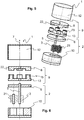
- Fig. 1 shows an exploded view of a first pump assembly 1 in a perspective view.
- Fig. 2 shows the exploded view of the first pump assembly 1 according to Fig. 1 in a side view in section.
- Fig. 3 shows the first pump assembly 1 according to Fig. 1 and 2 in a side view in section and
- Fig. 4 the first pump assembly 1 according to Fig. 3 in a top view.
- Inlet and outlet lines for the fluid 4 and electrical components are not shown here, since their arrangement is usually known to those skilled in the art.
- the pump arrangement 1 comprises a first housing 2 with a first side wall 6 and a receptacle 10 for the drive means 3, 21; here two meshing gear rotors.
- the drive means 3, 21 are rotatably mounted in the first housing 2 for conveying a fluid 4, wherein a first drive shaft 5 of the first drive means 3 extends through the first side wall 6 of the first housing 2 along an axial direction 7 therethrough.
- a first rotor 8 of a first axial flow electric drive 9 is arranged on the first drive shaft 5.
- the first housing 2 surrounds the drive means 3, 21 in particular vapor-tight and liquid-tight, wherein connections for the supply and discharge of the fluid 4 to be delivered are provided.
- the first drive shaft 5 extends through a first side wall 6 of the first housing 2, wherein a liquid-tight seal between the first side wall 6 and the first drive shaft 5 is also provided here.
- the first axial flow electric drive 9 comprises a (first) stator 13 and a first rotor 8, which are arranged coaxially with one another.
- the coils 15 of the stator 13 cooperate with magnets 22 of the first rotor 8 for generating a torque for driving the first rotor 8 and thus the first drive shaft 5 in the circumferential direction 16.
- the stator 13 has a plurality of coils 15, which are arranged in a circumferential direction 16 evenly spaced on a return plate of the stator 13.
- the first drive shaft 5 is supported only within the first housing 2 via radial bearings (which receive forces in the radial direction 24) and possibly thrust bearings (which receive forces in the axial direction 7). Outside the first housing 2, the first drive shaft 5 is arranged unsupported.
- the first Axialpound electric drive 9 is arranged in a second housing 12 that is repeatably connected to the first housing 2 releasably connected.
- the first Axialpound electric drive 9 is arranged protected from the fluid to be delivered 4, wherein the individual components of the pump assembly 1 are mutually independently interchangeable and / or to be maintained.
- the first rotor 8 is arranged immediately adjacent to the first side wall 6 and between the first side wall 6 and the stator 13 of the first axial flow electric drive 9.
- the first drive shaft 5 can be made very short, since the first rotor 8 connected to the first drive shaft 8 is disposed immediately adjacent to the first end wall 6, through which the first drive shaft 5, starting from the first housing 2, in the second housing 12 extends into it.
- the stator 13 comprises a soft magnetic material 17, for example a so-called “soft magnetic composite” (SMC), or a combination of electrical sheets and SMC.
- SMC soft magnetic composite
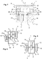
- Fig. 5 to 7 show a second pump assembly.
- 1 Fig. 5 shows an exploded view of a second pump assembly 1 in a perspective view.
- Fig. 6 shows the exploded view of the second pump assembly 1 according to Fig. 5 in a side view in section.
- Fig. 7 shows the second pump assembly 1 according to FIGS. 5 and 6 in a side view in section.
- Fig. 1 to 4 is referred to.
- the first rotor 8 and the stator 13 are arranged reversed.
- the stator 13 of the first axial flow electric drive 9 is arranged directly adjacent to the first side wall 6 and between the first side wall 6 and the first rotor 8.
- the first drive shaft 5 is longer to carry out, since it also extends through the stator 13 through to the first rotor 8.
- the stator 13 can be used with its coils 15 as a heating element 25 of the first housing 2.
- the heat development occurring there can, for. B. are conductively introduced via the first side wall 6 in the first housing 2.
- the power electronics for example, a corresponding current can be made available for this, which flows through the coils 15 of the stator poles of the stator 13.
- the stator 13 is completely connected with its rear surface with the first housing 2, in this case with the first side wall 6.
- the first side wall 6 forms at least part of a fluid channel 4 (in the region of the first drive means 3 and the second drive means 21). In this case, at least a part of the first side wall 6 contacts the conveyed fluid 4 in the region of the channel (eg in the region of the drive means 3, 21).
- a heat conduction structure 26 is formed only in this subarea, so that the heat generated in the region of the stator 15 can be specifically delivered to the fluid 4 via the heat conduction structure 26.
- Fig. 8 shows a third pump assembly 1 in a side view.
- Fig. 1 to 7 is referred to.
- a second axial flow electric drive 18 outside of the first housing 2 in a third housing 23 and at one, the first side wall 6 opposite second side wall 19 of the first housing 2 arranged.
- the second axial-flow electric drive 18 is connected in a torque-transmitting manner to a second drive shaft 20 of the second drive means 21 arranged in the first housing 2, wherein the second drive means 21 is a second gear wheel which is arranged in mesh with the first gear wheel for conveying the fluid 4.
- Fig. 9 shows a fourth pump assembly 1 in a side view. On the comments too Fig. 8 will be referred.
- the second axial flow electric drive 18 is connected to transmit torque to the first drive shaft 5.
- Fig. 10 shows a fifth pump assembly 1 in a side view.
- the stator 13 ie its components, coils 15, cores and return ring 14
- the stator 13 is arranged in a radial direction 24 outside the at least one first drive means 3.
- the stator 13 ie at least one of the components of coils 15, cores and return ring 14
- the stator 13 along the axial direction 7 overlapping with the first housing 2, here overlapping with at least one bearing 11 (radial bearings, thrust bearings, plain bearings, friction bearings) of the first Drive shaft 5 and arranged overlapping with the at least one first drive means 3.
- This preferred embodiment allows a particularly compact construction of the pump arrangement 1, wherein (exclusively) the at least one first drive means 3, the first side wall 6 (with the bearing 11 eg as part of the first side wall 6) and the first rotor 8 along the axial direction 7 are arranged side by side and thus determine the size of the pump assembly 1 along the axial direction 7.
- Fig. 11 shows a sixth pump assembly 1 in a side view.
- the first drive shaft 5 is arranged outside of the first housing 2 supported by a bearing 11, the bearing 11 receiving forces acting exclusively in the axial direction 7. So here it is not a radial bearing, so a bearing 11 which serves the support against forces acting in the radial direction 24, arranged outside of the first housing 2.
- the first drive shaft 5 is mounted exclusively in the first housing 2, so that the space for otherwise required bearings 11 outside the first housing 2 is not needed. For a particularly compact design of the pump assembly 1 is possible.
Landscapes
- Engineering & Computer Science (AREA)
- Mechanical Engineering (AREA)
- General Engineering & Computer Science (AREA)
- Rotary Pumps (AREA)
- Details And Applications Of Rotary Liquid Pumps (AREA)
Description
- Die vorliegende Erfindung betrifft eine Pumpenanordnung, zumindest umfassend ein erstes Gehäuse, in dem zumindest ein erstes Antriebsmittel zur Förderung eines Fluids drehbar gelagert angeordnet ist, wobei eine erste Antriebswelle des ersten Antriebsmittels sich zumindest durch eine erste Seitenwand des ersten Gehäuses entlang einer axialen Richtung hindurch erstreckt. Insbesondere handelt es sich bei der Pumpenanordnung um eine Fördereinrichtung für eine Wasser-Harnstoff-Lösung (z. B. Adblue), die bevorzugt in einem Kraftfahrzeug zur Behandlung eines Abgases eines Verbrennungsmotors eingesetzt wird.
- Solche Pumpenanordnungen für Wasser-Harnstoff-Lösungen sind seit langem bekannt. Dabei wird üblicherweise eine elektrische Antriebseinheit an die Antriebswelle des Antriebsmittels angeschlossen. Über die Antriebswelle solcher Rotationspumpen wird das Antriebsmittel zur Förderung eines Fluids angetrieben. Als Antriebsmittel sind z. B. Zahnradrotoren (bei Zahnradpumpen) bekannt. Gerade für die Anwendung in Kraftfahrzeugen ist eine möglichst kompakt bauende Pumpenanordnung bereitzustellen, wobei insbesondere Geräusche der Pumpenanordnung so weit wie möglich zu vermeiden sind. Weiterhin ist bei der Förderung von Wasser-Harnstoff-Lösungen zu beachten, dass ein Einfrieren der Lösung in den Leitungen möglichst vermieden wird. Üblicherweise wird daher die Wasser-Harnstoff-Lösung aus der Leitung zurück in einen Vorratstank gefördert. Dafür ist das Antriebsmittel jedoch auch in der entgegengesetzten Drehrichtung anzutreiben.
- Die
JP 2007-166693 - Die
US 2013/0071268 A1 offenbart eine Urea-Zahnrad-Pumpe, die koaxial und seitlich benachbart zu einem Elektroantrieb angeordnet ist. Der Elektroantrieb umfasst einen Rotor und einen in der radialen Richtung außerhalb des Rotors angeordneten Stator. Die Antriebswelle der Pumpe ist über ein Lager außerhalb und über ein weiteres Lager innerhalb des Pumpengehäuses gelagert. - Die
EP 2 273 121 A2 offenbart eine Zahnradpumpe, die über einen koaxial zur Pumpe angeordneten magnetischen Antrieb mit ersten Magneten und zweiten Magneten angetrieben wird. - Die
DE 102 58 364 A1 offenbart einen Elektroantrieb mit Rotor und Stator zum Antrieb einer Pumpe. Der Antrieb ist über zwei Lager gelagert. Die Pumpe wird seitlich benachbart zum Antrieb angeordnet. - Die
US 2014/0265664 A1 offenbart einen Axialflussmotor mit Stator und Rotor, über den eine Antriebswelle zum Antrieb einer Pumpe (nicht dargestellt und nicht weiter spezifiziert) angetrieben wird. Weiter ist eine Lüfteranordnung zur Kühlung des Elektroantriebs vorgesehen. Die Antriebswelle ist im Bereich des Motors über Lager gelagert. - Hiervon ausgehend ist es Aufgabe der vorliegenden Erfindung, die mit Bezug auf den Stand der Technik geschilderten Probleme zumindest zu lindern oder gar zu lösen. Insbesondere soll eine kompakt bauende Pumpenanordnung vorgeschlagen werden, die sich durch eine geringe Geräuschentwicklung auszeichnet.
- Zur Lösung dieser Aufgaben wird eine Pumpenanordnung gemäß den Merkmalen des Patentanspruchs 1 vorgeschlagen. Vorteilhafte Weiterbildungen sind Gegenstand der abhängigen Patentansprüche. Die in den Patentansprüchen einzeln aufgeführten Merkmale sind in technologisch sinnvoller Weise miteinander kombinierbar und können durch erläuternde Sachverhalte aus der Beschreibung und Details aus den Figuren ergänzt werden, wobei weitere Ausführungsvarianten der Erfindung aufgezeigt werden.
- Die Erfindung betrifft eine Pumpenanordnung, zumindest umfassend ein erstes Gehäuse, in dem zumindest ein erstes Antriebsmittel zur Förderung eines Fluids drehbar gelagert angeordnet ist, wobei eine erste Antriebswelle des ersten Antriebsmittels sich zumindest durch eine erste Seitenwand des ersten Gehäuses entlang einer axialen Richtung hindurch erstreckt; wobei außerhalb des ersten Gehäuses zumindest ein erster Rotor eines ersten Axialfluss-Elektroantriebs auf der ersten Antriebswelle angeordnet ist, wobei der erste Axialfluss-Elektroantrieb nur einen (ersten - dem ersten Axialfluss-Elektroantrieb und erster Rotor zugeordneten) Stator aufweist (also insbesondere keinen weiteren (zweiten) Stator).
- Insbesondere umschließt das erste Gehäuse zumindest das erste Antriebsmittel flüssigkeitsdicht, wobei Anschlüsse zum Zu- und Ableiten des zu fördernden Fluids vorgesehen sind. Die erste Antriebswelle erstreckt sich durch eine erste Seitenwand des ersten Gehäuses hindurch, wobei auch hier eine flüssigkeitsdichte Abdichtung zwischen der ersten Seitenwand und der ersten Antriebswelle vorgesehen ist. Außerhalb des ersten Gehäuses ist ein erster Rotor eines ersten Axialfluss-Elektroantriebs (AFM: Axialflussmotor) vorgesehen, der auf der ersten Antriebswelle zur Übertragung eines Drehmoments hin zu dem ersten Antriebsmittel angeordnet ist. Infolge der getrennten Anordnung von Antriebsmittel und Elektroantrieb kann eine Beschädigung des Elektroantriebs durch das geförderte Fluid vermieden werden.
- Insbesondere umschließt das erste Gehäuse zumindest das erste Antriebsmittel, wobei Anschlüsse zum Zu- und Ableiten des zu fördernden Fluids vorgesehen sind. Die erste Antriebswelle erstreckt sich durch eine erste Seitenwand des ersten Gehäuses hindurch. Außerhalb des ersten Gehäuses ist ein erster Rotor eines ersten Axialfluss-Elektroantriebs (AFM: Axialflussmotor) vorgesehen, der auf der ersten Antriebswelle zur Übertragung eines Drehmoments hin zu dem ersten Antriebsmittel angeordnet ist. Bevorzugt ist das erste Gehäuse nicht flüssigkeitsdicht ausgeführt, so dass das zu fördernde Fluid als Leckagestrom, z. B. entlang der ersten Antriebswelle, aus dem ersten Gehäuse austreten kann. Allerdings ist das erste Gehäuse bevorzugt so ausgeführt, dass infolge dieses Leckagestroms aus dem ersten Gehäuse (also ein Fluidabfluss und/oder Fluidzufluss nicht ausschließlich über die Anschlüsse zum Zu- und Ableiten des Fluids) keine wesentliche Beeinträchtigung der Förderleistung der Pumpenanordnung erfolgt. Insbesondere beträgt der Leckagestrom höchstens 5 % der Förderleistung (des Fördervolumenstroms) der Pumpenanordnung.
- Der erste Axialfluss-Elektroantrieb umfasst einen (einzelnen) Stator und einen ersten Rotor, die koaxial zueinander angeordnet sind. Der Stator kann ein weichmagnetisches Material aufweisen, zum Beispiel ein sogenanntes "Soft Magnetic Composite" (SMC), oder eine Kombination aus Elektroblechen und SMC. Die Spulen des Stators umfassen Kerne, die bevorzugt aus einem weichmagnetischen Material verpresst und verbackt hergestellt sind. Das SMC-Material wird hierbei nicht gesintert. Vielmehr erfolgt eine Temperierung auf unterhalb einer Schmelztemperatur, die jedoch ausreichend ist, dass die Kerne ihre Geometrie dauerhaft bewahren.
- Der Rotor des Axialfluss-Elektroantriebs kann Permanentmagnete oder auch weichmagnetische Elemente zum Beispiel in Aussparungen aufweisen. So kann mit Permanentmagneten als Axialfluss-Elektromotor ein permanenterregter Synchron- oder bürstenloser Gleichstrommotor, abgekürzt BLDC, gebildet werden, während beispielsweise mit weichmagnetischen Elementen ein Reluktanzmotor als Elektromotor in axialer Bauweise geschaffen werden kann.
- Der Aufbau eines Stators, insbesondere unter Nutzung von SMC sowie weitere Einzelheiten auch betreffend einen Rotor gehen beispielsweise aus der nachveröffentlichten
PCT/EP2015/075036 - Der erste Axialfluss-Elektroantrieb weist insbesondere eine elektrische Leistungsaufnahme von weniger als 100 Watt, bevorzugt von weniger als 50 Watt auf. Insbesondere wird das Fluid mit einem Förderdruck von höchstens 10 bar gefördert.
- Die erste Antriebswelle ist außerhalb des ersten Gehäuses ungelagert oder durch zumindest ein Lager gelagert, das ausschließlich in der axialen Richtung wirkende Kräfte aufnimmt. Es ist hier also insbesondere kein Radiallager, also ein Lager, das der Abstützung gegenüber in radialer Richtung wirkenden Kräften dient, außerhalb des ersten Gehäuses erforderlich. Die erste Antriebswelle ist also insbesondere ausschließlich in dem ersten Gehäuse gelagert, so dass der Bauraum für sonst erforderliche Lager außerhalb des ersten Gehäuses nicht benötigt wird. Damit ist eine besonders kompakte Ausführung der Pumpenanordnung möglich.
- Dabei können als Lager sogenannte Reiblager oder Gleitlager eingesetzt werden. Bevorzugt ist zumindest die erste Antriebswelle ausschließlich über das erste Gehäuse gelagert, z. B. über die erste Seitenwand und/oder eine zweite Seitenwand, wobei insbesondere das Material der Seitenwände die Lagerfläche bildet.
- Insbesondere kann dabei ein Leckagestrom des zu fördernden Fluids entlang der ersten Antriebswelle eine Schmierung der Lager bewirken. Bevorzugt ist ein Druckraum der Pumpenanordnung über eine Öffnung zumindest in der ersten Seitenwand mit einem Bereich außerhalb des ersten Gehäuses fluidtechnisch verbunden. Damit kann ein (hinsichtlich der Menge) kontrollierter Volumenstrom des zu fördernden Fluids aus dem ersten Gehäuse austreten und über die Lager zurück in das erste Gehäuse strömen.
- Gemäß einer weiteren vorteilhaften Ausgestaltung ist der erste Axialfluss-Elektroantrieb in einem zweiten Gehäuse angeordnet, dass mit dem ersten Gehäuse wiederholbar lösbar verbindbar ist. Damit ist der erste Axialfluss-Elektroantrieb gegenüber dem zu fördernden Fluid geschützt angeordnet, wobei die einzelnen Komponenten der Pumpenanordnung voneinander unabhängig austauschbar und/oder zu warten sind.
- Insbesondere ist der erste Rotor unmittelbar benachbart zur ersten Seitenwand und zwischen der ersten Seitenwand und einem Stator des ersten Axialfluss-Elektroantriebs angeordnet. Bei dieser Anordnung kann die erste Antriebswelle sehr kurz ausgeführt sein, da der mit der ersten Antriebswelle verbundene erste Rotor unmittelbar benachbart zur ersten Stirnwand angeordnet ist, durch die sich die erste Antriebswelle, ausgehend von dem ersten Gehäuse, in das zweite Gehäuse hinein erstreckt.
- Gemäß einer anderen Ausgestaltung ist ein Stator des ersten Axialfluss-Elektroantriebs unmittelbar benachbart zur ersten Seitenwand und zwischen der ersten Seitenwand und dem ersten Rotor angeordnet. Hier ist die erste Antriebswelle länger auszuführen, da sie sich auch durch den Stator hindurch bis hin zum ersten Rotor erstreckt.
- Bevorzugt ist der Stator (also dessen Komponenten, insbesondere Spulen, Kerne und Rückschlussring) in einer radialen Richtung außerhalb des zumindest einen ersten Antriebsmittels angeordnet.
- Bevorzugt ist der Stator (also zumindest eine der Komponenten von Spule, Kern und Rückschlussring) entlang der axialen Richtung überlappend mit dem ersten Gehäuse, bevorzugt überlappend mit zumindest einem Lager der ersten Antriebswelle, besondere bevorzugt überlappend mit dem zumindest einen ersten Antriebsmittel angeordnet.
- Diese bevorzugte Ausgestaltung ermöglicht einen besonders kompakten Aufbau der Pumpenanordnung, wobei (ausschließlich) das zumindest eine erste Antriebsmittel, die erste Seitenwand und der erste Rotor entlang der axialen Richtung nebeneinander angeordnet sind und somit die Baugröße der Pumpenanordnung entlang der axialen Richtung bestimmen.
- Insbesondere ist der Stator mit der ersten Seitenwand untrennbar verbunden. Insbesondere bildet der Stator zumindest einen Teil der ersten Stirnwand.
- Bevorzugt ist das erste Antriebsmittel ein erster Zahnradrotor. Dieser kann z. B. als Bestandteil einer Zahnradpumpe ausgeführt sein, wobei die Zahnradpumpe als Außenzahnradpumpe mit bevorzugt Evolventenverzahnung, als Innenzahnradpumpe oder auch als Zahnringpumpe aufgebaut sein kann, beispielsweise als Gerotorpumpe oder als Sichelpumpe. Weiterhin kann die Zahnradpumpe eine Schraubenspindelpumpe sein.
- Insbesondere ist zumindest der erste Zahnradrotor aus einem Kunststoff hergestellt.
- Insbesondere wird vorgeschlagen, zumindest den ersten Zahnradrotor aus einem gesinterten Material mit einer Porosität herzustellen, wobei der Zahnradrotor neben der Porosität ein weiteres Schallminderungsmittel aufweist. Hierbei wird insbesondere auf den Inhalt der
DE 10 2015 201 873 verwiesen. Es hat sich herausgestellt, dass durch eine Variation der Dichte im Radkörper des Zahnradrotors der Übertragungspfad der Körperschallwellen von der Erzeugung am Zahnkranz zur Nabe unterbrochen bzw. die Schallwellen so gebrochen oder reflektiert werden können, das das Körperschallsignal am Ausgang, nämlich der Welle/Bohrung des Zahnradrotors, deutlich geringer ausfällt. Die Variationen der Dichte können dabei rotationssymmetrisch oder lokal ausgeführt werden. Ebenso möglich ist ein Zahnradrotor in Scheibenanordnung mit unterschiedlich ausgeführten Dichten. Der Winkel der Ebene der einzelnen Schichten kann dabei von der Vorzugsebene, der horizontalen Ebene des Bauteils abweichen. Da sich der Körperschall in Materialien mit höherer Dichte besser ausbreitet als in Materialien mit geringerer Dichte ist es auch möglich, Schallführungskanäle in den Zahnradrotor oder nur in die Verzahnung einzubringen, die die Körperschallwellen gezielt umlenken oder abschwächen. Dabei können die Kanäle und/oder lokalen Dichtevariationen sowohl mit reinem Material unterschiedlicher Dichte ausgefüllt werden als auch mit Kombinationen aus verschiedenen Materialien wie Eisenpulver oder auch Öl. - Diese schallmindernden Geometrien können mit unterschiedlichen Herstellverfahren realisiert werden. Hierzu gehören zum Beispiel ein intelligenter Füllschuh, insbesondere ein sich rotatorisch drehender Füllschuh zur Befüllung mit zumindest zwei unterschiedlichen Materialien, so wie es zum Beispiel aus der
DE 10 2014 006 374 hervorgeht. Dadurch können zum Beispiel Dichtevariationen bereits beim Pressvorgang hergestellt werden. Des Weiteren kann auch ein als Grün-in-Grün bezeichnetes Herstellungsverfahren, wie es aus derDE 10 2009 042 598 hervorgeht, genutzt werden, um beispielsweise Dichtevariationen zu erzeugen. Herstellungsverfahren wie ein konventionelles Pressen von metallischem Pulver, wie es auch in abgewandelter Form aus derWO 2013/067995 A1 hervorgeht, sowie eine additive Fertigung von metallischem Werkstoff und/oder Kunststoff, zum Beispiel mit einer Vorrichtung, wie sie aus derDE 10 2013 103006 A1 beispielhaft hervorgeht, können ebenfalls zum Einsatz kommen, insbesondere um geräuscharme Zahnradrotoren herzustellen. Es können aber auch Herstellungsverfahren eingesetzt werden, wie sie grundsätzlich aus derEP 2 221 131 A1 , derEP 1 407 877 A1 , derEP 1 34527 A2 JP S60-162 702 A - Eine Weiterbildung sieht vor, dass der Stator durch das erste Gehäuse gebildet wird. Beispielsweise kann hierzu in das erste Gehäuse der Stator eingelassen sein. Dieses ist beispielsweis mittels eines Verfahrens Grün-in-Grün möglich, was oben schon beschrieben wurde und auf das diesbezüglich verwiesen wird. Auch kann der Stator in das erste Gehäuse eingesetzt werden. So kann zum Beispiel eine Außenseite des ersten Gehäuses einen Ausschnitt aufweisen, in den der Stator eingepresst werden kann. Beispielsweise kann das erste Gehäuse in diesem Bereich aus Kunststoff sein, während der Stator aus metallischem Material hergestellt ist. Beispielsweise kann ein Rückschlussring eingepresst werden, auf dem die Statorpole angeordnet sind.
- Insbesondere ist bei dieser Ausgestaltung vorteilhaft, wenn der Stator (also zumindest eine der Komponenten von Spule, Kern und Rückschlussring) überlappend mit zumindest einem Lager der ersten Antriebswelle, besondere bevorzugt überlappend mit dem zumindest einen ersten Antriebsmittel angeordnet ist.
- Bevorzugt ist es, wenn das erste Gehäuse zumindest in einem Bereich benachbart zu dem Stator, vorzugsweise dem elektromagnetischen Rückschluss(-ring) und insbesondere zu den Kernen des Stators ein amagnetisches Material aufweist. Dadurch wird die notwendige Ausbildung des elektromagnetischen Feldes zur Erzeugung eines Drehmoments am Rotor des Axialfluss-Motors nicht oder nur gering gestört.
- Gemäß einer weiteren vorteilhaften Ausgestaltung ist ein zweiter Axialfluss-Elektroantrieb außerhalb des ersten Gehäuses und an einer, der ersten Seitenwand gegenüberliegenden zweiten Seitenwand des ersten Gehäuses angeordnet; wobei der zweite Axialfluss-Elektroantrieb entweder mit der ersten Antriebswelle oder mit einer zweiten Antriebswelle eines in dem ersten Gehäuse angeordneten zweiten Antriebsmittels drehmomentübertragend verbunden ist.
- Insbesondere ist der zweite Axialfluss-Elektroantrieb mit der zweiten Antriebswelle drehmomentübertragend verbunden, wobei das zweite Antriebsmittel ein zweiter Zahnradrotor ist, der mit dem ersten Zahnradrotor zur Förderung des Fluids kämmend angeordnet ist, wobei die zwei Zahnradrotoren über die zwei Axialfluss-Elektroantriebe verspannt zueinander angeordnet sind.
- Die Verspannung der zwei Zahnradrotoren bewirkt ein ständig spielfreies Kämmen der Zahnradrotoren, so dass Geräusche minimiert werden können. Insbesondere kann diese Verspannung auch bei Umkehrung der Drehrichtung der Antriebsmittel eingestellt werden (z. B. bei Rückförderung einer Wasser-Harnstoff-Lösung in einen Tank zur Vermeidung von Eisbildung in den Leitungen).
- Gemäß einer weiteren Ausgestaltung sind die beiden Axialfluss-Elektroantriebe zwar gleich aufgebaut, aber in Bezug auf die Anordnung der Statorpole versetzt zueinander an entgegengesetzten Enden des Zahnradrotors angeordnet. Durch ein Versetzen ist es beispielsweise möglich, einen Ausgleich zwischen erzeugten elektromagnetischen Wellen des Axialfluss-Elektroantriebs zu erzielen. Beispielsweise kann je nach Aufbau der Axialfluss-Elektroantriebe der Versatz so ausgelegt sein, dass sich Wellental, verursacht durch den ersten Axialfluss- Elektroantrieb, und Wellenberg, verursacht durch den zweiten Axialfluss- Elektroantrieb, in ihrer Drehmomentwirkung quasi überlagern. Dadurch gelingt ein ausgeglichener, vor allem gleichförmigerer Antrieb des Zahnradrotors. Das führt wiederum zu einer Reduzierung von Geräuschemissionen an den miteinander kämmenden Zahnrädern. Die Vergleichmäßigung des Drehmoments an der angetriebenen Welle führt insbesondere zu einem ruhigeren Kontaktieren der einzelnen Zähne der miteinander kämmenden Zahnräder. Ein Anschlagen der miteinander kämmenden Zähne lässt sich zumindest minimieren.
- Insbesondere bildet zumindest der erste Axialfluss-Elektroantrieb mindestens ein Heizelement, das über mindestens eine Wärmeleitstruktur mit der ersten Seitenwand wärmeleitend verbunden ist. Insbesondere kann der eine Stator mit seinen Spulen als Heizelement des ersten Gehäuses genutzt werden. Die dort auftretende Wärmeentwicklung kann z. B. konduktiv über die erste Seitenwand in das erste Gehäuse eingebracht werden. Durch die Leistungselektronik kann hierfür zum Beispiel ein entsprechender Strom zur Verfügung gestellt werden, der durch die Spulen der Statorpole strömt. Um einen guten Wärmeübergang zu schaffen, ist es besonders vorteilhaft, wenn der Stator mit seiner Rückfläche vollständig mit dem ersten Gehäuse verbunden ist, also z. B. die erste Seitenwand selber bildet. Der Stator wird daher als erste Seitenwand bevorzugt direkt auf das erste Gehäuse aufgesetzt oder z. B. in eine als Deckel des ersten Gehäuses ausgeführte erste Seitenwand eingesetzt.
- Zur Herstellung des Stators bzw. der ersten Seitenwand bzw. von Wärmeleitstrukturen kann beispielsweise ein metallisches, elektrisch leitfähiges Pulver mitgenutzt werden, zum Beispiel bei einem rotatorisch sich drehenden Füllschuh zur Befüllung mit zumindest zwei unterschiedlichen Materialien, so wie es zum Beispiel aus der
DE 10 2014 006 374 hervorgeht. Dadurch können zum Beispiel nicht nur Dichtevariationen sondern auch konduktive Wärmewege (Wärmeleitstruktur) und elektrisch beheizbare Wege (Wärmeleitstruktur) bereits beim Pressvorgang (des Stators, der ersten Seitenwand) hergestellt werden. - Die erste Seitenwand bildet insbesondere zumindest einen Teil eines Fluid führenden Kanals. Bevorzugt kontaktiert zumindest ein Teil der Seitenwand das geförderte Fluid im Bereich des Kanals (z. B. im Bereich der Antriebsmittel). Insbesondere ist nur dieser Teilbereich mit einer Wärmeleitstruktur ausgebildet, so dass die im Bereich des Stators generierte Wärme über die Wärmeleitstruktur gezielt an das Fluid abgegeben werden kann.
- Für die Wärmeerzeugung kann beispielsweise auf einen Temperatursensor zurückgegriffen werden. Ein derartiger Temperatursensor kann an der Pumpenanordnung selbst angebracht sein. Eine weitere Ausgestaltung sieht vor, dass ein vorhandener Temperatursensor an einer Leistungselektronik der Pumpenanordnung genutzt wird um zu entscheiden, ob und wie stark ein Strom durch den Stator geschickt wird. Derartiges kann beispielsweise in einem Steuergerät hinterlegt werden, welches der Harnstoffeinspritzung zugeordnet ist. So kann beispielsweise bei Detektierung zu tiefer Temperaturen schon vor dem eigentlichen Start des Verbrennungsmotors die Beheizung erfolgen. Denkt man an heutige Keyless-Systeme zum Öffnen und Starten, könnte daher das Öffnen schon die vorsorgliche Beheizung auslösen. Damit wäre eine Beheizung der Pumpe selbst möglich, die beispielsweise ergänzt wird mit Wärme, die z.B. von einer Tankbeheizung oder als Abwärme von einem noch warmen Verbrennungsmotor herrührt. Damit könnte das System auch bei tiefen Temperaturen sofort einsatzfähig sein bzw. einsatzfähig bleiben.
- Weiterhin ist gemäß einer Ausgestaltung vorgesehen, dass eine Kompensation einer unterschiedlichen Wärmedehnung der verschiedenen Werkstoffe in der Pumpenanordnung vorgesehen ist. Das Fluid bzw. die Harnstofflösung kann Temperaturen ausgesetzt werden, die umgebungsbedingt aber auch betriebsbedingt stark schwanken können, zum Beispiel bei tiefem Frost von zum Beispiel - 35°C und aufgrund der Bedingungen beim Einspritzen der Harnstofflösung von zumindest kurzfristig +100°C. Dieses wirkt sich ebenfalls auf die einzelnen Komponenten auf, die aufgrund der Umgebungstemperatur sich schon unterschiedlich dehnen bzw. kontrahieren. Daher kann die Pumpenanordnung beispielsweise in ihrem Inneren eine federgespannte Nachführung aufweisen, die eine Minimierung von zum Beispiel ansonsten entstehenden Spaltmaßen erlaubt.
- Es wird die Verwendung der erfindungsgemäßen Pumpenanordnung zur Förderung einer Wasser-Harnstoff-Lösung in einem Kraftfahrzeug vorgeschlagen.
- Neben einem ersten Zahnrad kann die Kraftfahrzeug-Ureapumpe auch ein zweites Zahnrad auf einer zweiten Welle aufweisen, wobei die beiden Zahnräder miteinander kämmen und dabei einen Druck aufbauen. Es können beide Zahnräder aus dem gleichen Material aufgebaut sein. Es können aber auch beide Zahnräder aus voneinander unterschiedlichem Material aufgebaut sein, Beispielsweise kann das eine Zahnrad aus einem Kunststoff bestehen, das andere Zahnrad aus einem Metall. Auch können Verbundzahnräder zum Einsatz kommen, das heißt, das Zahnrad weist unterschiedliche Materialien auf, beispielsweise einen Kern aus Metall und eine Oberfläche aus Kunststoff oder umgekehrt. Bevorzugt werden bei miteinander kämmenden Zahnrädern schrägverzahnte Zahnräder genutzt. Allerdings kann es für die Druckerhöhung ebenfalls von Vorteil sein, geradverzahnte Zahnräder zu nutzen. Bevorzugt werden das oder die Zahnräder als Stirnrad-Zahnräder mit einer Fertigungsqualität hergestellt, bei dem das Zahnrad eine Qualitätsgüte des ausgelegten Zahnrads gemäß DIN 3961 und DIN 3962 bezüglich zumindest eines Parameters, vorzugsweise eines totalen Profilfehlers Fα, eines Profilwinkelfehlers fHα und eines Profilformfehlers fα von zumindest der Güte 6, bevorzugt von zumindest der Güte 5 oder besser aufweist bei zumindest einem dieser Werte, insbesondere zumindest diesen drei Werten. Beispielsweise kann auch das erste Gehäuse eine zusätzliche Dämpfung aufweisen, mittels der ein Pumpgeräusch verringert wird. Derartige Dichtevariationen wie oben beschrieben können zum Beispiel hierbei eingesetzt werden. Auch andere hier beschriebene Möglichkeiten, einen Körperschall im oder am Gehäuse zu minimieren, können zum Einsatz kommen, die zusätzliche Dämpfung zu erzielen.
- Des Weiteren kann eine Dämpfung von einem Geräusch oder einem Geräuschspektrum nicht nur durch unterschiedliche Sintermaterialien und/oder Dichten bei Sintermaterialien erzielt werden. Auch durch gezielte Offenporigkeit des Sintermaterials bzw. Verschließen von Poren, beispielsweise durch Zugabe von Kupfer, zum Beispiel in Verbindung mit unterschiedlichen Dichten, evtl. durch Einsatz von Grün-in-Grün-Herstellungsverfahren mit Innen- und Außenmaterial wie auch durch ein oder mehrere Überzüge an Bauteilen zum Beispiel mit einem Kunststoff, kann eine Dämpfung gezielt eingestellt werden.
- Die Erfindung, sowie das technische Umfeld werden nachfolgend anhand der Figuren näher erläutert. Es ist darauf hinzuweisen, dass die Erfindung durch die gezeigten Ausführungsbeispiele nicht beschränkt werden soll. Insbesondere ist, soweit nicht explizit anders dargestellt, auch möglich, Teilaspekte der in den Figuren erläuterten Sachverhalte zu extrahieren und mit anderen Bestandteilen und Erkenntnissen aus der vorliegenden Beschreibung samt Figuren zu kombinieren. Gleiche Bezugszeichen bezeichnen gleiche Gegenstände, so dass ggf. Erläuterungen aus anderen Figuren ergänzend herangezogen werden können. Es zeigen schematisch:
- Fig. 1:
- eine Explosionsdarstellung einer ersten Pumpenanordnung in perspektivischer Ansicht;
- Fig. 2:
- die Explosionsdarstellung der ersten Pumpenanordnung gemäß
Fig. 1 in einer Seitenansicht im Schnitt; - Fig. 3:
- die erste Pumpenanordnung gemäß
Fig. 1 und 2 in einer Seitenansicht im Schnitt; - Fig. 4:
- die erste Pumpenanordnung gemäß
Fig. 3 in einer Draufsicht; - Fig. 5:
- eine Explosionsdarstellung einer zweiten Pumpenanordnung in perspektivischer Ansicht;
- Fig. 6:
- die Explosionsdarstellung der zweiten Pumpenanordnung gemäß
Fig. 5 in einer Seitenansicht im Schnitt; - Fig. 7:
- die zweite Pumpenanordnung gemäß
Fig. 5 und 6 in einer Seitenansicht im Schnitt; - Fig. 8:
- eine dritte Pumpenanordnung in einer Seitenansicht;
- Fig. 9:
- eine vierte Pumpenanordnung in einer Seitenansicht;
- Fig. 10:
- eine fünfte Pumpenanordnung in einer Seitenansicht; und
- Fig. 11:
- eine sechste Pumpenanordnung in einer Seitenansicht.
-
Fig. 1 zeigt eine Explosionsdarstellung einer ersten Pumpenanordnung 1 in perspektivischer Ansicht.Fig. 2 zeigt die Explosionsdarstellung der ersten Pumpenanordnung 1 gemäßFig. 1 in einer Seitenansicht im Schnitt.Fig. 3 zeigt die erste Pumpenanordnung 1 gemäßFig. 1 und 2 in einer Seitenansicht im Schnitt undFig. 4 die die erste Pumpenanordnung 1 gemäßFig. 3 in einer Draufsicht. DieFig. 1 bis 4 werden im Folgenden gemeinsam beschrieben. Zu- und Ableitungen für das Fluid 4 sowie elektrische Komponenten (Steuereinheit, elektrische Anschlüsse etc.) sind hier nicht gezeigt, da deren Anordnung dem Fachmann üblicherweise bekannt ist. - Die Pumpenanordnung 1 umfasst ein erstes Gehäuse 2 mit einer ersten Seitenwand 6 und einer Aufnahme 10 für die Antriebsmittel 3, 21; hier zwei miteinander kämmende Zahnradrotoren. Die Antriebsmittel 3, 21 sind in dem ersten Gehäuse 2 zur Förderung eines Fluids 4 drehbar gelagert angeordnet, wobei eine erste Antriebswelle 5 des ersten Antriebsmittels 3 sich durch die erste Seitenwand 6 des ersten Gehäuses 2 entlang einer axialen Richtung 7 hindurch erstreckt. Außerhalb des ersten Gehäuses 2 ist ein erster Rotor 8 eines ersten Axialfluss-Elektroantriebs 9 auf der ersten Antriebswelle 5 angeordnet.
- Das erste Gehäuse 2 umschließt die Antriebsmittel 3, 21 insbesondere dampf- und flüssigkeitsdicht, wobei Anschlüsse zum Zu- und Ableiten des zu fördernden Fluids 4 vorgesehen sind. Die erste Antriebswelle 5 erstreckt sich durch eine erste Seitenwand 6 des ersten Gehäuses 2 hindurch, wobei auch hier eine flüssigkeitsdichte Abdichtung zwischen der ersten Seitenwand 6 und der ersten Antriebswelle 5 vorgesehen ist. Der erste Axialfluss-Elektroantrieb 9 umfasst einen (ersten) Stator 13 und einen ersten Rotor 8, die koaxial zueinander angeordnet sind. Die Spulen 15 des Stators 13 wirken mit Magneten 22 des ersten Rotors 8 zur Erzeugung eines Drehmoments zum Antrieb des ersten Rotors 8 und damit der ersten Antriebswelle 5 in der Umfangsrichtung 16 zusammen. Der Stator 13 weist eine Mehrzahl von Spulen 15 auf, die in einer Umfangsrichtung 16 gleichmäßig voneinander beabstandet auf einer Rückschlussplatte des Stators 13 angeordnet sind.
- Die erste Antriebswelle 5 ist nur innerhalb des ersten Gehäuses 2 über Radiallager (die Kräfte in der radialen Richtung 24 aufnehmen) und ggf. Axiallager (die Kräfte in der axialen Richtung 7 aufnehmen) gelagert. Außerhalb des ersten Gehäuses 2 ist die erste Antriebswelle 5 ungelagert angeordnet.
- Der erste Axialfluss-Elektroantrieb 9 ist in einem zweiten Gehäuse 12 angeordnet, dass mit dem ersten Gehäuse 2 wiederholbar lösbar verbindbar ist. Damit ist der erste Axialfluss-Elektroantrieb 9 gegenüber dem zu fördernden Fluid 4 geschützt angeordnet, wobei die einzelnen Komponenten der Pumpenanordnung 1 voneinander unabhängig austauschbar und/oder zu warten sind.
- Hier ist der erste Rotor 8 unmittelbar benachbart zur ersten Seitenwand 6 und zwischen der ersten Seitenwand 6 und dem Stator 13 des ersten Axialfluss-Elektroantriebs 9 angeordnet. Bei dieser Anordnung kann die erste Antriebswelle 5 sehr kurz ausgeführt sein, da der mit der ersten Antriebswelle 5 verbundene erste Rotor 8 unmittelbar benachbart zur ersten Stirnwand 6 angeordnet ist, durch die sich die erste Antriebswelle 5, ausgehend von dem ersten Gehäuse 2, in das zweite Gehäuse 12 hinein erstreckt.
- Der Stator 13 weist ein weichmagnetisches Material 17 auf, zum Beispiel ein sogenanntes "Soft Magnetic Composite" (SMC), oder eine Kombination aus Elektroblechen und SMC.
-
Fig. 5 bis 7 zeigen eine zweite Pumpenanordnung 1.Fig. 5 zeigt eine Explosionsdarstellung einer zweiten Pumpenanordnung 1 in perspektivischer Ansicht.Fig. 6 zeigt die Explosionsdarstellung der zweiten Pumpenanordnung 1 gemäßFig. 5 in einer Seitenansicht im Schnitt.Fig. 7 zeigt die zweite Pumpenanordnung 1 gemäßFig. 5 und 6 in einer Seitenansicht im Schnitt. - Auf die Ausführungen zu
Fig. 1 bis 4 wird Bezug genommen. Im Unterschied zur ersten Pumpenanordnung 1 sind hier der erste Rotor 8 und der Stator 13 vertauscht angeordnet. Hier ist der Stator 13 des ersten Axialfluss-Elektroantriebs 9 unmittelbar benachbart zur ersten Seitenwand 6 und zwischen der ersten Seitenwand 6 und dem ersten Rotor 8 angeordnet. Hier ist die erste Antriebswelle 5 länger auszuführen, da sie sich auch durch den Stator 13 hindurch bis hin zum ersten Rotor 8 erstreckt. - Hier kann der Stator 13 mit seinen Spulen 15 als Heizelement 25 des ersten Gehäuses 2 genutzt werden. Die dort auftretende Wärmeentwicklung kann z. B. konduktiv über die erste Seitenwand 6 in das erste Gehäuse 2 eingebracht werden. Durch die Leistungselektronik kann hierfür zum Beispiel ein entsprechender Strom zur Verfügung gestellt werden, der durch die Spulen 15 der Statorpole des Stators 13 strömt. Um einen guten Wärmeübergang zu schaffen, ist der Stator 13 mit seiner Rückfläche vollständig mit dem ersten Gehäuse 2 verbunden, hier also mit der ersten Seitenwand 6.
- Die erste Seitenwand 6 bildet zumindest einen Teil eines Fluid 4 führenden Kanals (in dem Bereich des ersten Antriebsmittels 3 und des zweiten Antriebsmittels 21). Dabei kontaktiert zumindest ein Teil der ersten Seitenwand 6 das geförderte Fluid 4 im Bereich des Kanals (z. B. im Bereich der Antriebsmittel 3, 21). Hier ist nur in diesem Teilbereich eine Wärmeleitstruktur 26 ausbildet, so dass die im Bereich des Stators 15 generierte Wärme über die Wärmeleitstruktur 26 gezielt an das Fluid 4 abgegeben werden kann.
-
Fig. 8 zeigt eine dritte Pumpenanordnung 1 in einer Seitenansicht. Auf die Ausführungen zuFig. 1 bis 7 wird Bezug genommen. Im Unterschied zu der ersten und zweiten Pumpenanordnung 1 ist hier ein zweiter Axialfluss-Elektroantrieb 18 außerhalb des ersten Gehäuses 2 in einem dritten Gehäuse 23 und an einer, der ersten Seitenwand 6 gegenüberliegenden zweiten Seitenwand 19 des ersten Gehäuses 2 angeordnet. Der zweite Axialfluss-Elektroantrieb 18 ist mit einer zweiten Antriebswelle 20 des in dem ersten Gehäuse 2 angeordneten zweiten Antriebsmittels 21 drehmomentübertragend verbunden, wobei das zweite Antriebsmittel 21 ein zweiter Zahnradrotor ist, der mit dem ersten Zahnradrotor zur Förderung des Fluids 4 kämmend angeordnet ist. -
Fig. 9 zeigt eine vierte Pumpenanordnung 1 in einer Seitenansicht. Auf die Ausführungen zuFig. 8 wird verwiesen. Im Unterschied zu der dritten Pumpenanordnung 1 ist der zweite Axialfluss-Elektroantrieb 18 mit der ersten Antriebswelle 5 drehmomentübertragend verbunden. -
Fig. 10 zeigt eine fünfte Pumpenanordnung 1 in einer Seitenansicht. Auf die Ausführungen zu denFig. 5 bis 7 wird Bezug genommen. Im Unterschied zu denFig. 5 bis 7 ist der Stator 13 (also dessen Komponenten, Spulen 15, Kerne und Rückschlussring 14) in einer radialen Richtung 24 außerhalb des zumindest einen ersten Antriebsmittels 3 angeordnet. Dabei ist der Stator 13 (also zumindest eine der Komponenten von Spulen 15, Kerne und Rückschlussring 14) entlang der axialen Richtung 7 überlappend mit dem ersten Gehäuse 2, hier überlappend mit zumindest einem Lager 11 (Radiallager, Axiallager, Gleitlager, Reiblager) der ersten Antriebswelle 5 und überlappend mit dem zumindest einen ersten Antriebsmittel 3 angeordnet. Diese bevorzugte Ausgestaltung ermöglicht einen besonders kompakten Aufbau der Pumpenanordnung 1, wobei (ausschließlich) das zumindest eine erste Antriebsmittel 3, die erste Seitenwand 6 (mit dem Lager 11 z. B. als Bestandteil der ersten Seitenwand 6) und der erste Rotor 8 entlang der axialen Richtung 7 nebeneinander angeordnet sind und somit die Baugröße der Pumpenanordnung 1 entlang der axialen Richtung 7 bestimmen. -
Fig. 11 zeigt eine sechste Pumpenanordnung 1 in einer Seitenansicht. Auf die Ausführungen zu denFig. 1 bis 4 wird Bezug genommen. Im Unterschied zu der ersten Pumpenanordnung 1 ist hier die erste Antriebswelle 5 außerhalb des ersten Gehäuses 2 durch ein Lager 11 gelagert angeordnet, wobei das Lager 11 ausschließlich in der axialen Richtung 7 wirkende Kräfte aufnimmt. Es ist hier also kein Radiallager, also ein Lager 11, das der Abstützung gegenüber in radialer Richtung 24 wirkenden Kräften dient, außerhalb des ersten Gehäuses 2 angeordnet. Auch hier ist die erste Antriebswelle 5 ausschließlich in dem ersten Gehäuse 2 gelagert, so dass der Bauraum für sonst erforderliche Lager 11 außerhalb des ersten Gehäuses 2 nicht benötigt wird. Damit ist eine besonders kompakte Ausführung der Pumpenanordnung 1 möglich.
Claims (14)
- Pumpenanordnung (1), zumindest umfassend ein erstes Gehäuse (2), in dem zumindest ein erstes Antriebsmittel (3) zur Förderung eines Fluids (4) drehbar gelagert angeordnet ist, wobei eine erste Antriebswelle (5) des ersten Antriebsmittels (3) sich zumindest durch eine erste Seitenwand (6) des ersten Gehäuses (2) entlang einer axialen Richtung (7) hindurch erstreckt; wobei außerhalb des ersten Gehäuses (2) zumindest ein erster Rotor (8) eines ersten Axialfluss-Elektroantriebs (9) auf der ersten Antriebswelle (5) angeordnet ist, wobei der erste Axialfluss-Elektroantrieb (9) nur einen Stator (13) aufweist; dadurch gekennzeichnet, dass die erste Antriebswelle (5) außerhalb des ersten Gehäuses (2) ungelagert ist oder durch zumindest ein Lager (11) gelagert ist, das ausschließlich in der axialen Richtung (7) wirkende Kräfte aufnimmt.
- Pumpenanordnung (1) nach Patentanspruch 1, wobei der erste Axialfluss-Elektroantrieb (9) in einem zweiten Gehäuse (12) angeordnet ist, dass mit dem ersten Gehäuse (2) wiederholbar lösbar verbindbar ist.
- Pumpenanordnung (1) nach einem der vorhergehenden Patentansprüche, wobei der erste Rotor (8) unmittelbar benachbart zur ersten Seitenwand (6) und zwischen der ersten Seitenwand (6) und einem Stator (13) des ersten Axialfluss-Elektroantriebs (9) angeordnet ist.
- Pumpenanordnung (1) nach einem der vorhergehenden Patentansprüche 1 bis 2, wobei der Stator (13) unmittelbar benachbart zur ersten Seitenwand (6) und zwischen der ersten Seitenwand (6) und dem ersten Rotor (8) angeordnet ist.
- Pumpenanordnung (1) nach Patentanspruch 4, wobei der Stator (13) in einer radialen Richtung (24) außerhalb des zumindest einen ersten Antriebsmittels (3) angeordnet ist.
- Pumpenanordnung (1) nach Patentanspruch 5, wobei der Stator (13) entlang der axialen Richtung (7) überlappend mit dem ersten Gehäuse (2) angeordnet ist.
- Pumpenanordnung (1) nach Patentanspruch 6, wobei der Stator (13) entlang der axialen Richtung (7) überlappend mit dem zumindest einen ersten Antriebsmittel (3) angeordnet ist.
- Pumpenanordnung (1) nach einem der vorhergehenden Patentansprüche 4 bis 7, wobei der Stator (13) mit der ersten Seitenwand (6) untrennbar verbunden ist.
- Pumpenanordnung (1) nach einem der vorhergehenden Patentansprüche, wobei das erste Antriebsmittel (3) ein erster Zahnradrotor ist.
- Pumpenanordnung (1) nach einem der vorhergehenden Patentansprüche, wobei der Stator (13) des Axialfluss-Elektroantriebs (9) SMC (soft magnetic composite) umfassende Materialien (17) aufweist.
- Pumpenanordnung (1) nach einem der vorhergehenden Patentansprüche, wobei zumindest der erste Axialfluss-Elektroantrieb (9) mindestens ein Heizelement (25) bildet, das über mindestens eine Wärmeleitstruktur (26) mit der ersten Seitenwand (6) wärmeleitend verbunden ist.
- Pumpenanordnung (1) nach einem der vorhergehenden Patentansprüche, wobei ein zweiter Axialfluss-Elektroantrieb (18) außerhalb des ersten Gehäuses (2) und an einer, der ersten Seitenwand (6) gegenüberliegenden zweiten Seitenwand (19) des ersten Gehäuses (2) angeordnet ist; wobei der zweite Axialfluss-Elektroantrieb (18) entweder mit der ersten Antriebswelle (5) oder mit einer zweiten Antriebswelle (20) eines in dem ersten Gehäuse (2) angeordneten zweiten Antriebsmittels (21) drehmomentübertragend verbunden ist.
- Pumpenanordnung (1) nach Patentanspruch 12, wobei der zweite Axialfluss-Elektroantrieb (18) mit der zweiten Antriebswelle (20) drehmomentübertragend verbunden ist und wobei das zweite Antriebsmittel (21) ein zweiter Zahnradrotor ist, der mit dem ersten Zahnradrotor zur Förderung des Fluids (4) kämmend angeordnet ist, wobei die zwei Zahnradrotoren über die zwei Axialfluss-Elektroantriebe (9, 18) verspannt zueinander angeordnet sind.
- Verwendung der Pumpenanordnung (1) nach einem der vorhergehenden Patentansprüche zur Förderung einer Wasser-Harnstoff-Lösung in einem Kraftfahrzeug.
Priority Applications (1)
| Application Number | Priority Date | Filing Date | Title |
|---|---|---|---|
| EP19202447.9A EP3617448B1 (de) | 2016-02-22 | 2017-02-22 | Pumpenanordnung |
Applications Claiming Priority (2)
| Application Number | Priority Date | Filing Date | Title |
|---|---|---|---|
| DE102016103051.1A DE102016103051A1 (de) | 2016-02-22 | 2016-02-22 | Pumpenanordnung |
| PCT/EP2017/053992 WO2017144499A1 (de) | 2016-02-22 | 2017-02-22 | Pumpenanordnung mit axialfluss-elektroantrieb |
Related Child Applications (1)
| Application Number | Title | Priority Date | Filing Date |
|---|---|---|---|
| EP19202447.9A Division EP3617448B1 (de) | 2016-02-22 | 2017-02-22 | Pumpenanordnung |
Publications (2)
| Publication Number | Publication Date |
|---|---|
| EP3405650A1 EP3405650A1 (de) | 2018-11-28 |
| EP3405650B1 true EP3405650B1 (de) | 2019-10-23 |
Family
ID=58162546
Family Applications (2)
| Application Number | Title | Priority Date | Filing Date |
|---|---|---|---|
| EP17707223.8A Active EP3405650B1 (de) | 2016-02-22 | 2017-02-22 | Pumpenanordnung mit axialfluss-elektroantrieb |
| EP19202447.9A Active EP3617448B1 (de) | 2016-02-22 | 2017-02-22 | Pumpenanordnung |
Family Applications After (1)
| Application Number | Title | Priority Date | Filing Date |
|---|---|---|---|
| EP19202447.9A Active EP3617448B1 (de) | 2016-02-22 | 2017-02-22 | Pumpenanordnung |
Country Status (5)
| Country | Link |
|---|---|
| US (1) | US20190055941A1 (de) |
| EP (2) | EP3405650B1 (de) |
| CN (1) | CN108884713B (de) |
| DE (1) | DE102016103051A1 (de) |
| WO (1) | WO2017144499A1 (de) |
Families Citing this family (4)
| Publication number | Priority date | Publication date | Assignee | Title |
|---|---|---|---|---|
| DE102018101330A1 (de) * | 2018-01-22 | 2019-07-25 | Logicdata Electronic & Software Entwicklungs Gmbh | Linearaktuator für ein Möbelsystem, elektrisch verstellbares Möbelsystem, Einbauverfahren für einen Linearaktuator in ein Möbelsystem und Möbelsystemanordnung |
| DE102018105129A1 (de) * | 2018-03-06 | 2019-09-12 | Gkn Sinter Metals Engineering Gmbh | Verfahren zum Betreiben eines elektrischen Motors |
| DE102018105136A1 (de) | 2018-03-06 | 2019-09-12 | Gkn Sinter Metals Engineering Gmbh | Verfahren zum Betreiben einer Pumpenanordnung |
| DE102019110511A1 (de) * | 2019-04-23 | 2020-10-29 | Schwäbische Hüttenwerke Automotive GmbH | Pumpvorrichtung mit einem Deckel und einer Fluidleitung |
Family Cites Families (37)
| Publication number | Priority date | Publication date | Assignee | Title |
|---|---|---|---|---|
| DE955467C (de) | 1953-07-25 | 1957-01-03 | Opel Adam Ag | Stirnzahnrad, insbesondere zum Antrieb der Nockenwelle in Brennkraftmaschinen |
| DE3329093A1 (de) | 1983-08-11 | 1985-02-28 | Siemens AG, 1000 Berlin und 8000 München | Dynamischer mos-schaltkreis |
| JPS60162702A (ja) | 1984-02-03 | 1985-08-24 | Hitachi Powdered Metals Co Ltd | 複層成形体の成形方法 |
| JP3574191B2 (ja) | 1994-11-07 | 2004-10-06 | 本田技研工業株式会社 | 多層焼結部品用成形体の製造方法 |
| US6012350A (en) | 1997-04-08 | 2000-01-11 | Jatco Corporation | Internal gear |
| US6132186A (en) * | 1997-08-06 | 2000-10-17 | Shurflo Pump Manufacturing Co. | Impeller pump driven by a dynamo electric machine having a stator comprised of a mass of metal particles |
| JP3845798B2 (ja) | 2001-04-27 | 2006-11-15 | 株式会社豊田中央研究所 | 複合粉末充填方法と複合粉末充填装置並びに複合粉末成形方法と複合粉末成形装置 |
| DE10207018A1 (de) * | 2002-02-20 | 2003-08-28 | Linde Ag | Baueinheit mit einem Elektromotor und einer Hydraulikpumpe |
| JP2005344126A (ja) | 2002-10-04 | 2005-12-15 | Hitachi Powdered Metals Co Ltd | 焼結歯車 |
| DE10258364A1 (de) * | 2002-12-12 | 2004-06-24 | Daimlerchrysler Ag | Elektrische Antriebsvorrichtung |
| ATE411468T1 (de) * | 2002-12-23 | 2008-10-15 | Grundfos Nonox As | Dosierpumpenaggregat |
| FI20050866A0 (fi) * | 2005-08-31 | 2005-08-31 | Axco Motors Oy | Aggregaatin jäähdytysjärjestelmä |
| JP2007166693A (ja) * | 2005-12-09 | 2007-06-28 | Aisan Ind Co Ltd | アキシャル型モータと燃料ポンプ |
| DE102006039958A1 (de) * | 2006-08-25 | 2008-02-28 | Busch Produktions Gmbh | Drehschieber-Vakuumpumpe bzw.-Verdichter in Blockbauweise mit fliegend gelagertem Scheibenläufer-Synchronmotor |
| JP2008099456A (ja) * | 2006-10-12 | 2008-04-24 | Aisan Ind Co Ltd | アキシャルギャップ型モータ及びそれを用いた流体ポンプ |
| JP5206201B2 (ja) * | 2008-07-30 | 2013-06-12 | 株式会社デンソー | 尿素水供給ポンプおよびその製造方法 |
| JP2010031814A (ja) * | 2008-07-31 | 2010-02-12 | Hitachi Ltd | 油冷式スクリュー圧縮機とモータ駆動システム及びモータ制御装置 |
| EP2221131A1 (de) | 2009-05-29 | 2010-08-25 | Sandvik Intellectual Property AB | Verfahren zur Herstellung eines kompakten Puder- und gesinterten Verbundkörpers |
| ITMI20090188U1 (it) * | 2009-06-08 | 2010-12-09 | Fluid O Tech Srl | Assieme di contenimento per una pompa volumetrica |
| DE102009029534A1 (de) | 2009-09-17 | 2011-03-24 | Robert Bosch Gmbh | Fördermodul sowie Dosiersystem mit einem solchen Fördermodul |
| DE102009042598A1 (de) | 2009-09-23 | 2011-03-24 | Gkn Sinter Metals Holding Gmbh | Verfahren zur Herstellung eines Grünlings |
| DE102009042603A1 (de) | 2009-09-23 | 2011-03-24 | Gkn Sinter Metals Holding Gmbh | Verfahren zur Herstellung eines Verbundbauteils |
| DE102009055375A1 (de) | 2009-12-29 | 2011-06-30 | Robert Bosch GmbH, 70469 | Pumpe zum Fördern von Fluiden in eine Förder- und eine Rückförderrichtung |
| DE102011077949A1 (de) * | 2011-06-22 | 2012-12-27 | Robert Bosch Gmbh | Zahnradpumpe |
| KR101220393B1 (ko) * | 2011-09-20 | 2013-01-09 | 기아자동차주식회사 | 유레아 에스씨알 시스템용 펌프 구조 |
| KR101326838B1 (ko) * | 2011-11-02 | 2013-11-11 | 현대자동차주식회사 | 요소수 펌프 구조 |
| DE102011118054A1 (de) | 2011-11-09 | 2013-05-16 | Dorst Technologies Gmbh & Co. Kg | Verfahren und Presse zum Pressen eines Presskörpers aus zumindest zwei verschiedenen metallischen und/oder keramischen pulver-und/oder granulatförmigen Materialien |
| JP5927870B2 (ja) * | 2011-11-30 | 2016-06-01 | アイシン精機株式会社 | 電動ポンプ |
| GB201205591D0 (en) | 2012-03-29 | 2012-05-16 | Materials Solutions | Apparatus and methods for additive-layer manufacturing of an article |
| JP2013241838A (ja) * | 2012-05-17 | 2013-12-05 | Aisin Seiki Co Ltd | 流体ポンプ |
| DE102012025210B4 (de) | 2012-12-28 | 2014-08-14 | Gkn Sinter Metals Holding Gmbh | Geteiltes Zahnrad |
| DE102013102032A1 (de) * | 2013-03-01 | 2014-09-04 | Netzsch Pumpen & Systeme Gmbh | Schraubenspindelpumpe |
| US9467030B2 (en) * | 2013-03-15 | 2016-10-11 | Regal Beloit Australia Pty Ltd | Air-cooled electric machine and method of assembling the same |
| DE102013206593A1 (de) * | 2013-04-12 | 2014-10-30 | Siemens Aktiengesellschaft | xialflussmaschine in Leichtbauweise |
| DE102014006374A1 (de) | 2014-05-05 | 2015-11-05 | Gkn Sinter Metals Engineering Gmbh | Vorrichtung zur Herstellung eines Rohlings nebst Verfahren hierzu und Rohling |
| GB2531745A (en) | 2014-10-28 | 2016-05-04 | Moeller Motors Kg | Electrical machines with SMC cores |
| DE102015201873A1 (de) | 2015-02-03 | 2016-08-18 | Gkn Sinter Metals Engineering Gmbh | Leises Zahnrad |
-
2016
- 2016-02-22 DE DE102016103051.1A patent/DE102016103051A1/de not_active Withdrawn
-
2017
- 2017-02-22 US US16/078,257 patent/US20190055941A1/en active Pending
- 2017-02-22 CN CN201780012791.1A patent/CN108884713B/zh active Active
- 2017-02-22 WO PCT/EP2017/053992 patent/WO2017144499A1/de not_active Ceased
- 2017-02-22 EP EP17707223.8A patent/EP3405650B1/de active Active
- 2017-02-22 EP EP19202447.9A patent/EP3617448B1/de active Active
Non-Patent Citations (1)
| Title |
|---|
| None * |
Also Published As
| Publication number | Publication date |
|---|---|
| EP3617448A1 (de) | 2020-03-04 |
| EP3405650A1 (de) | 2018-11-28 |
| CN108884713B (zh) | 2021-06-22 |
| CN108884713A (zh) | 2018-11-23 |
| EP3617448B1 (de) | 2023-03-29 |
| WO2017144499A1 (de) | 2017-08-31 |
| US20190055941A1 (en) | 2019-02-21 |
| DE102016103051A1 (de) | 2017-08-24 |
Similar Documents
| Publication | Publication Date | Title |
|---|---|---|
| EP3179106B1 (de) | Elektromotorisch angetriebene flüssigkeitspumpe | |
| EP3289221B1 (de) | Fluidpumpe | |
| EP2072826B1 (de) | Rotor für einem Spaltrohrmotor | |
| EP3617448B1 (de) | Pumpenanordnung | |
| DE102012102156B4 (de) | Pumpe und Außenring für eine Pumpe | |
| WO2013127626A2 (de) | Pumpenanordnung | |
| DE69904834T2 (de) | Elektromotorisch angetriebene pumpe | |
| WO2011035972A1 (de) | Elektrische förderpumpe und verfahren zum antreiben einer elektrischen förderpumpe | |
| EP2795128A2 (de) | Innenzahnradpumpe | |
| EP2558725B1 (de) | Elektrische förderpumpe und verfahren zum antreiben einer elektrischen förderpumpe | |
| DE10159147A1 (de) | Hydraulische Zahnradpumpe | |
| DE102015115841A1 (de) | Pumpen-Motor-Einheit mit einer Kühlung eines die Pumpe antreibenden Elektromotors mittels Leckagefluid | |
| EP3299627B1 (de) | Förderpumpe | |
| WO2012038213A2 (de) | Pumpe mit elektromotor | |
| EP2756194A1 (de) | Zahnradpumpe und verfahren zum herstellen einer zahnradpumpe | |
| EP2756195A1 (de) | Pumpe mit elektromotor | |
| EP2780598B1 (de) | Innenzahnradpumpe | |
| EP0987437B1 (de) | Innenzahnrad- bzw. Innenkonturrotor-Druckmittelpumpe | |
| DE102012206961A1 (de) | Pumpe mit Elektromotor | |
| DE3740365A1 (de) | Fluegelzellenverdichter fuer druckluft | |
| DE102007030528A1 (de) | Umlaufverdrängermaschine | |
| DE102024107002A1 (de) | Schraubenspindelpumpe mit Druckentlastung | |
| DE102015119264A1 (de) | Elektromotor | |
| DE102009045468A1 (de) | Zahnradpumpe | |
| EP2756183A1 (de) | Pumpenanordnung für ein hochdruckeinspritzsystem |
Legal Events
| Date | Code | Title | Description |
|---|---|---|---|
| STAA | Information on the status of an ep patent application or granted ep patent |
Free format text: STATUS: UNKNOWN |
|
| STAA | Information on the status of an ep patent application or granted ep patent |
Free format text: STATUS: THE INTERNATIONAL PUBLICATION HAS BEEN MADE |
|
| PUAI | Public reference made under article 153(3) epc to a published international application that has entered the european phase |
Free format text: ORIGINAL CODE: 0009012 |
|
| STAA | Information on the status of an ep patent application or granted ep patent |
Free format text: STATUS: REQUEST FOR EXAMINATION WAS MADE |
|
| 17P | Request for examination filed |
Effective date: 20180806 |
|
| AK | Designated contracting states |
Kind code of ref document: A1 Designated state(s): AL AT BE BG CH CY CZ DE DK EE ES FI FR GB GR HR HU IE IS IT LI LT LU LV MC MK MT NL NO PL PT RO RS SE SI SK SM TR |
|
| AX | Request for extension of the european patent |
Extension state: BA ME |
|
| GRAP | Despatch of communication of intention to grant a patent |
Free format text: ORIGINAL CODE: EPIDOSNIGR1 |
|
| STAA | Information on the status of an ep patent application or granted ep patent |
Free format text: STATUS: GRANT OF PATENT IS INTENDED |
|
| DAV | Request for validation of the european patent (deleted) | ||
| DAX | Request for extension of the european patent (deleted) | ||
| INTG | Intention to grant announced |
Effective date: 20190524 |
|
| GRAS | Grant fee paid |
Free format text: ORIGINAL CODE: EPIDOSNIGR3 |
|
| GRAA | (expected) grant |
Free format text: ORIGINAL CODE: 0009210 |
|
| STAA | Information on the status of an ep patent application or granted ep patent |
Free format text: STATUS: THE PATENT HAS BEEN GRANTED |
|
| AK | Designated contracting states |
Kind code of ref document: B1 Designated state(s): AL AT BE BG CH CY CZ DE DK EE ES FI FR GB GR HR HU IE IS IT LI LT LU LV MC MK MT NL NO PL PT RO RS SE SI SK SM TR |
|
| REG | Reference to a national code |
Ref country code: GB Ref legal event code: FG4D Free format text: NOT ENGLISH |
|
| REG | Reference to a national code |
Ref country code: CH Ref legal event code: EP |
|
| REG | Reference to a national code |
Ref country code: IE Ref legal event code: FG4D Free format text: LANGUAGE OF EP DOCUMENT: GERMAN |
|
| REG | Reference to a national code |
Ref country code: DE Ref legal event code: R096 Ref document number: 502017002658 Country of ref document: DE |
|
| REG | Reference to a national code |
Ref country code: AT Ref legal event code: REF Ref document number: 1193846 Country of ref document: AT Kind code of ref document: T Effective date: 20191115 |
|
| REG | Reference to a national code |
Ref country code: NL Ref legal event code: MP Effective date: 20191023 |
|
| REG | Reference to a national code |
Ref country code: LT Ref legal event code: MG4D |
|
| PG25 | Lapsed in a contracting state [announced via postgrant information from national office to epo] |
Ref country code: LT Free format text: LAPSE BECAUSE OF FAILURE TO SUBMIT A TRANSLATION OF THE DESCRIPTION OR TO PAY THE FEE WITHIN THE PRESCRIBED TIME-LIMIT Effective date: 20191023 Ref country code: NL Free format text: LAPSE BECAUSE OF FAILURE TO SUBMIT A TRANSLATION OF THE DESCRIPTION OR TO PAY THE FEE WITHIN THE PRESCRIBED TIME-LIMIT Effective date: 20191023 Ref country code: PL Free format text: LAPSE BECAUSE OF FAILURE TO SUBMIT A TRANSLATION OF THE DESCRIPTION OR TO PAY THE FEE WITHIN THE PRESCRIBED TIME-LIMIT Effective date: 20191023 Ref country code: LV Free format text: LAPSE BECAUSE OF FAILURE TO SUBMIT A TRANSLATION OF THE DESCRIPTION OR TO PAY THE FEE WITHIN THE PRESCRIBED TIME-LIMIT Effective date: 20191023 Ref country code: SE Free format text: LAPSE BECAUSE OF FAILURE TO SUBMIT A TRANSLATION OF THE DESCRIPTION OR TO PAY THE FEE WITHIN THE PRESCRIBED TIME-LIMIT Effective date: 20191023 Ref country code: NO Free format text: LAPSE BECAUSE OF FAILURE TO SUBMIT A TRANSLATION OF THE DESCRIPTION OR TO PAY THE FEE WITHIN THE PRESCRIBED TIME-LIMIT Effective date: 20200123 Ref country code: GR Free format text: LAPSE BECAUSE OF FAILURE TO SUBMIT A TRANSLATION OF THE DESCRIPTION OR TO PAY THE FEE WITHIN THE PRESCRIBED TIME-LIMIT Effective date: 20200124 Ref country code: FI Free format text: LAPSE BECAUSE OF FAILURE TO SUBMIT A TRANSLATION OF THE DESCRIPTION OR TO PAY THE FEE WITHIN THE PRESCRIBED TIME-LIMIT Effective date: 20191023 Ref country code: BG Free format text: LAPSE BECAUSE OF FAILURE TO SUBMIT A TRANSLATION OF THE DESCRIPTION OR TO PAY THE FEE WITHIN THE PRESCRIBED TIME-LIMIT Effective date: 20200123 Ref country code: PT Free format text: LAPSE BECAUSE OF FAILURE TO SUBMIT A TRANSLATION OF THE DESCRIPTION OR TO PAY THE FEE WITHIN THE PRESCRIBED TIME-LIMIT Effective date: 20200224 |
|
| PG25 | Lapsed in a contracting state [announced via postgrant information from national office to epo] |
Ref country code: RS Free format text: LAPSE BECAUSE OF FAILURE TO SUBMIT A TRANSLATION OF THE DESCRIPTION OR TO PAY THE FEE WITHIN THE PRESCRIBED TIME-LIMIT Effective date: 20191023 Ref country code: IS Free format text: LAPSE BECAUSE OF FAILURE TO SUBMIT A TRANSLATION OF THE DESCRIPTION OR TO PAY THE FEE WITHIN THE PRESCRIBED TIME-LIMIT Effective date: 20200224 Ref country code: HR Free format text: LAPSE BECAUSE OF FAILURE TO SUBMIT A TRANSLATION OF THE DESCRIPTION OR TO PAY THE FEE WITHIN THE PRESCRIBED TIME-LIMIT Effective date: 20191023 |
|
| PG25 | Lapsed in a contracting state [announced via postgrant information from national office to epo] |
Ref country code: AL Free format text: LAPSE BECAUSE OF FAILURE TO SUBMIT A TRANSLATION OF THE DESCRIPTION OR TO PAY THE FEE WITHIN THE PRESCRIBED TIME-LIMIT Effective date: 20191023 |
|
| REG | Reference to a national code |
Ref country code: DE Ref legal event code: R097 Ref document number: 502017002658 Country of ref document: DE |
|
| PG2D | Information on lapse in contracting state deleted |
Ref country code: IS |
|
| PG25 | Lapsed in a contracting state [announced via postgrant information from national office to epo] |
Ref country code: DK Free format text: LAPSE BECAUSE OF FAILURE TO SUBMIT A TRANSLATION OF THE DESCRIPTION OR TO PAY THE FEE WITHIN THE PRESCRIBED TIME-LIMIT Effective date: 20191023 Ref country code: EE Free format text: LAPSE BECAUSE OF FAILURE TO SUBMIT A TRANSLATION OF THE DESCRIPTION OR TO PAY THE FEE WITHIN THE PRESCRIBED TIME-LIMIT Effective date: 20191023 Ref country code: RO Free format text: LAPSE BECAUSE OF FAILURE TO SUBMIT A TRANSLATION OF THE DESCRIPTION OR TO PAY THE FEE WITHIN THE PRESCRIBED TIME-LIMIT Effective date: 20191023 Ref country code: ES Free format text: LAPSE BECAUSE OF FAILURE TO SUBMIT A TRANSLATION OF THE DESCRIPTION OR TO PAY THE FEE WITHIN THE PRESCRIBED TIME-LIMIT Effective date: 20191023 Ref country code: CZ Free format text: LAPSE BECAUSE OF FAILURE TO SUBMIT A TRANSLATION OF THE DESCRIPTION OR TO PAY THE FEE WITHIN THE PRESCRIBED TIME-LIMIT Effective date: 20191023 Ref country code: IS Free format text: LAPSE BECAUSE OF FAILURE TO SUBMIT A TRANSLATION OF THE DESCRIPTION OR TO PAY THE FEE WITHIN THE PRESCRIBED TIME-LIMIT Effective date: 20200223 |
|
| PLBE | No opposition filed within time limit |
Free format text: ORIGINAL CODE: 0009261 |
|
| STAA | Information on the status of an ep patent application or granted ep patent |
Free format text: STATUS: NO OPPOSITION FILED WITHIN TIME LIMIT |
|
| PG25 | Lapsed in a contracting state [announced via postgrant information from national office to epo] |
Ref country code: IT Free format text: LAPSE BECAUSE OF FAILURE TO SUBMIT A TRANSLATION OF THE DESCRIPTION OR TO PAY THE FEE WITHIN THE PRESCRIBED TIME-LIMIT Effective date: 20191023 Ref country code: SK Free format text: LAPSE BECAUSE OF FAILURE TO SUBMIT A TRANSLATION OF THE DESCRIPTION OR TO PAY THE FEE WITHIN THE PRESCRIBED TIME-LIMIT Effective date: 20191023 Ref country code: SM Free format text: LAPSE BECAUSE OF FAILURE TO SUBMIT A TRANSLATION OF THE DESCRIPTION OR TO PAY THE FEE WITHIN THE PRESCRIBED TIME-LIMIT Effective date: 20191023 |
|
| 26N | No opposition filed |
Effective date: 20200724 |
|
| REG | Reference to a national code |
Ref country code: CH Ref legal event code: PL |
|
| REG | Reference to a national code |
Ref country code: BE Ref legal event code: MM Effective date: 20200229 |
|
| PG25 | Lapsed in a contracting state [announced via postgrant information from national office to epo] |
Ref country code: MC Free format text: LAPSE BECAUSE OF FAILURE TO SUBMIT A TRANSLATION OF THE DESCRIPTION OR TO PAY THE FEE WITHIN THE PRESCRIBED TIME-LIMIT Effective date: 20191023 Ref country code: LU Free format text: LAPSE BECAUSE OF NON-PAYMENT OF DUE FEES Effective date: 20200222 |
|
| PG25 | Lapsed in a contracting state [announced via postgrant information from national office to epo] |
Ref country code: SI Free format text: LAPSE BECAUSE OF FAILURE TO SUBMIT A TRANSLATION OF THE DESCRIPTION OR TO PAY THE FEE WITHIN THE PRESCRIBED TIME-LIMIT Effective date: 20191023 Ref country code: CH Free format text: LAPSE BECAUSE OF NON-PAYMENT OF DUE FEES Effective date: 20200229 Ref country code: LI Free format text: LAPSE BECAUSE OF NON-PAYMENT OF DUE FEES Effective date: 20200229 |
|
| PG25 | Lapsed in a contracting state [announced via postgrant information from national office to epo] |
Ref country code: IE Free format text: LAPSE BECAUSE OF NON-PAYMENT OF DUE FEES Effective date: 20200222 Ref country code: FR Free format text: LAPSE BECAUSE OF NON-PAYMENT OF DUE FEES Effective date: 20200229 |
|
| PG25 | Lapsed in a contracting state [announced via postgrant information from national office to epo] |
Ref country code: BE Free format text: LAPSE BECAUSE OF NON-PAYMENT OF DUE FEES Effective date: 20200229 |
|
| GBPC | Gb: european patent ceased through non-payment of renewal fee |
Effective date: 20210222 |
|
| PG25 | Lapsed in a contracting state [announced via postgrant information from national office to epo] |
Ref country code: GB Free format text: LAPSE BECAUSE OF NON-PAYMENT OF DUE FEES Effective date: 20210222 |
|
| PG25 | Lapsed in a contracting state [announced via postgrant information from national office to epo] |
Ref country code: TR Free format text: LAPSE BECAUSE OF FAILURE TO SUBMIT A TRANSLATION OF THE DESCRIPTION OR TO PAY THE FEE WITHIN THE PRESCRIBED TIME-LIMIT Effective date: 20191023 Ref country code: MT Free format text: LAPSE BECAUSE OF FAILURE TO SUBMIT A TRANSLATION OF THE DESCRIPTION OR TO PAY THE FEE WITHIN THE PRESCRIBED TIME-LIMIT Effective date: 20191023 Ref country code: CY Free format text: LAPSE BECAUSE OF FAILURE TO SUBMIT A TRANSLATION OF THE DESCRIPTION OR TO PAY THE FEE WITHIN THE PRESCRIBED TIME-LIMIT Effective date: 20191023 |
|
| PG25 | Lapsed in a contracting state [announced via postgrant information from national office to epo] |
Ref country code: MK Free format text: LAPSE BECAUSE OF FAILURE TO SUBMIT A TRANSLATION OF THE DESCRIPTION OR TO PAY THE FEE WITHIN THE PRESCRIBED TIME-LIMIT Effective date: 20191023 |
|
| REG | Reference to a national code |
Ref country code: DE Ref legal event code: R081 Ref document number: 502017002658 Country of ref document: DE Owner name: GKN POWDER METALLURGY ENGINEERING GMBH, DE Free format text: FORMER OWNER: GKN SINTER METALS ENGINEERING GMBH, 42477 RADEVORMWALD, DE |
|
| REG | Reference to a national code |
Ref country code: AT Ref legal event code: MM01 Ref document number: 1193846 Country of ref document: AT Kind code of ref document: T Effective date: 20220222 |
|
| PG25 | Lapsed in a contracting state [announced via postgrant information from national office to epo] |
Ref country code: AT Free format text: LAPSE BECAUSE OF NON-PAYMENT OF DUE FEES Effective date: 20220222 |
|
| P01 | Opt-out of the competence of the unified patent court (upc) registered |
Effective date: 20230526 |
|
| PGFP | Annual fee paid to national office [announced via postgrant information from national office to epo] |
Ref country code: DE Payment date: 20260217 Year of fee payment: 10 |