EP3404745A1 - Method for manufacturing secondary battery electrode comprising pre-slitting process - Google Patents
Method for manufacturing secondary battery electrode comprising pre-slitting process Download PDFInfo
- Publication number
- EP3404745A1 EP3404745A1 EP17858601.2A EP17858601A EP3404745A1 EP 3404745 A1 EP3404745 A1 EP 3404745A1 EP 17858601 A EP17858601 A EP 17858601A EP 3404745 A1 EP3404745 A1 EP 3404745A1
- Authority
- EP
- European Patent Office
- Prior art keywords
- electrode
- forming
- secondary battery
- coated
- slurry
- Prior art date
- Legal status (The legal status is an assumption and is not a legal conclusion. Google has not performed a legal analysis and makes no representation as to the accuracy of the status listed.)
- Granted
Links
Images






Classifications
-
- H—ELECTRICITY
- H01—ELECTRIC ELEMENTS
- H01M—PROCESSES OR MEANS, e.g. BATTERIES, FOR THE DIRECT CONVERSION OF CHEMICAL ENERGY INTO ELECTRICAL ENERGY
- H01M4/00—Electrodes
- H01M4/02—Electrodes composed of, or comprising, active material
- H01M4/13—Electrodes for accumulators with non-aqueous electrolyte, e.g. for lithium-accumulators; Processes of manufacture thereof
- H01M4/139—Processes of manufacture
-
- B—PERFORMING OPERATIONS; TRANSPORTING
- B26—HAND CUTTING TOOLS; CUTTING; SEVERING
- B26F—PERFORATING; PUNCHING; CUTTING-OUT; STAMPING-OUT; SEVERING BY MEANS OTHER THAN CUTTING
- B26F1/00—Perforating; Punching; Cutting-out; Stamping-out; Apparatus therefor
- B26F1/02—Perforating by punching, e.g. with relatively-reciprocating punch and bed
- B26F1/12—Perforating by punching, e.g. with relatively-reciprocating punch and bed to notch margins of work
-
- H—ELECTRICITY
- H01—ELECTRIC ELEMENTS
- H01M—PROCESSES OR MEANS, e.g. BATTERIES, FOR THE DIRECT CONVERSION OF CHEMICAL ENERGY INTO ELECTRICAL ENERGY
- H01M4/00—Electrodes
- H01M4/02—Electrodes composed of, or comprising, active material
- H01M4/04—Processes of manufacture in general
-
- H—ELECTRICITY
- H01—ELECTRIC ELEMENTS
- H01M—PROCESSES OR MEANS, e.g. BATTERIES, FOR THE DIRECT CONVERSION OF CHEMICAL ENERGY INTO ELECTRICAL ENERGY
- H01M4/00—Electrodes
- H01M4/02—Electrodes composed of, or comprising, active material
- H01M4/04—Processes of manufacture in general
- H01M4/0402—Methods of deposition of the material
- H01M4/0404—Methods of deposition of the material by coating on electrode collectors
-
- H—ELECTRICITY
- H01—ELECTRIC ELEMENTS
- H01M—PROCESSES OR MEANS, e.g. BATTERIES, FOR THE DIRECT CONVERSION OF CHEMICAL ENERGY INTO ELECTRICAL ENERGY
- H01M4/00—Electrodes
- H01M4/02—Electrodes composed of, or comprising, active material
- H01M4/04—Processes of manufacture in general
- H01M4/0402—Methods of deposition of the material
- H01M4/0409—Methods of deposition of the material by a doctor blade method, slip-casting or roller coating
-
- H—ELECTRICITY
- H01—ELECTRIC ELEMENTS
- H01M—PROCESSES OR MEANS, e.g. BATTERIES, FOR THE DIRECT CONVERSION OF CHEMICAL ENERGY INTO ELECTRICAL ENERGY
- H01M4/00—Electrodes
- H01M4/02—Electrodes composed of, or comprising, active material
- H01M4/04—Processes of manufacture in general
- H01M4/0402—Methods of deposition of the material
- H01M4/0416—Methods of deposition of the material involving impregnation with a solution, dispersion, paste or dry powder
-
- H—ELECTRICITY
- H01—ELECTRIC ELEMENTS
- H01M—PROCESSES OR MEANS, e.g. BATTERIES, FOR THE DIRECT CONVERSION OF CHEMICAL ENERGY INTO ELECTRICAL ENERGY
- H01M4/00—Electrodes
- H01M4/02—Electrodes composed of, or comprising, active material
- H01M4/04—Processes of manufacture in general
- H01M4/043—Processes of manufacture in general involving compressing or compaction
- H01M4/0435—Rolling or calendering
-
- H—ELECTRICITY
- H01—ELECTRIC ELEMENTS
- H01M—PROCESSES OR MEANS, e.g. BATTERIES, FOR THE DIRECT CONVERSION OF CHEMICAL ENERGY INTO ELECTRICAL ENERGY
- H01M4/00—Electrodes
- H01M4/02—Electrodes composed of, or comprising, active material
- H01M4/04—Processes of manufacture in general
- H01M4/0471—Processes of manufacture in general involving thermal treatment, e.g. firing, sintering, backing particulate active material, thermal decomposition, pyrolysis
-
- H—ELECTRICITY
- H01—ELECTRIC ELEMENTS
- H01M—PROCESSES OR MEANS, e.g. BATTERIES, FOR THE DIRECT CONVERSION OF CHEMICAL ENERGY INTO ELECTRICAL ENERGY
- H01M4/00—Electrodes
- H01M4/02—Electrodes composed of, or comprising, active material
- H01M4/13—Electrodes for accumulators with non-aqueous electrolyte, e.g. for lithium-accumulators; Processes of manufacture thereof
-
- H—ELECTRICITY
- H01—ELECTRIC ELEMENTS
- H01M—PROCESSES OR MEANS, e.g. BATTERIES, FOR THE DIRECT CONVERSION OF CHEMICAL ENERGY INTO ELECTRICAL ENERGY
- H01M4/00—Electrodes
- H01M4/02—Electrodes composed of, or comprising, active material
- H01M4/64—Carriers or collectors
- H01M4/66—Selection of materials
-
- H—ELECTRICITY
- H01—ELECTRIC ELEMENTS
- H01M—PROCESSES OR MEANS, e.g. BATTERIES, FOR THE DIRECT CONVERSION OF CHEMICAL ENERGY INTO ELECTRICAL ENERGY
- H01M4/00—Electrodes
- H01M4/02—Electrodes composed of, or comprising, active material
- H01M4/64—Carriers or collectors
- H01M4/66—Selection of materials
- H01M4/661—Metal or alloys, e.g. alloy coatings
-
- H—ELECTRICITY
- H01—ELECTRIC ELEMENTS
- H01M—PROCESSES OR MEANS, e.g. BATTERIES, FOR THE DIRECT CONVERSION OF CHEMICAL ENERGY INTO ELECTRICAL ENERGY
- H01M50/00—Constructional details or processes of manufacture of the non-active parts of electrochemical cells other than fuel cells, e.g. hybrid cells
- H01M50/50—Current conducting connections for cells or batteries
- H01M50/531—Electrode connections inside a battery casing
-
- H—ELECTRICITY
- H01—ELECTRIC ELEMENTS
- H01M—PROCESSES OR MEANS, e.g. BATTERIES, FOR THE DIRECT CONVERSION OF CHEMICAL ENERGY INTO ELECTRICAL ENERGY
- H01M4/00—Electrodes
- H01M4/02—Electrodes composed of, or comprising, active material
- H01M4/24—Electrodes for alkaline accumulators
- H01M4/26—Processes of manufacture
-
- Y—GENERAL TAGGING OF NEW TECHNOLOGICAL DEVELOPMENTS; GENERAL TAGGING OF CROSS-SECTIONAL TECHNOLOGIES SPANNING OVER SEVERAL SECTIONS OF THE IPC; TECHNICAL SUBJECTS COVERED BY FORMER USPC CROSS-REFERENCE ART COLLECTIONS [XRACs] AND DIGESTS
- Y02—TECHNOLOGIES OR APPLICATIONS FOR MITIGATION OR ADAPTATION AGAINST CLIMATE CHANGE
- Y02E—REDUCTION OF GREENHOUSE GAS [GHG] EMISSIONS, RELATED TO ENERGY GENERATION, TRANSMISSION OR DISTRIBUTION
- Y02E60/00—Enabling technologies; Technologies with a potential or indirect contribution to GHG emissions mitigation
- Y02E60/10—Energy storage using batteries
-
- Y—GENERAL TAGGING OF NEW TECHNOLOGICAL DEVELOPMENTS; GENERAL TAGGING OF CROSS-SECTIONAL TECHNOLOGIES SPANNING OVER SEVERAL SECTIONS OF THE IPC; TECHNICAL SUBJECTS COVERED BY FORMER USPC CROSS-REFERENCE ART COLLECTIONS [XRACs] AND DIGESTS
- Y02—TECHNOLOGIES OR APPLICATIONS FOR MITIGATION OR ADAPTATION AGAINST CLIMATE CHANGE
- Y02P—CLIMATE CHANGE MITIGATION TECHNOLOGIES IN THE PRODUCTION OR PROCESSING OF GOODS
- Y02P70/00—Climate change mitigation technologies in the production process for final industrial or consumer products
- Y02P70/50—Manufacturing or production processes characterised by the final manufactured product
Definitions
- the present disclosure relates to a method of manufacturing an electrode for a secondary battery including a pre-slitting process.
- Recent trends in the development of the electronic industry can be summarized as wireless functions of a device, a mobile trend, and a transition from analog to digital.
- the rapid dissemination of wireless phones (so-called mobile phones) and notebook computers, and the transition from analog cameras to digital cameras may be referred to as representative examples of such trends.
- the lithium secondary battery has a structure in which an electrode assembly of a positive electrode/a separator/a negative electrode is embedded in a sealed container together with an electrolyte.
- an electrode generate current via the exchanges of ions
- a positive electrode and a negative electrode constituting the electrode have a structure in which an electrode active material is applied to an electrode current collector made of metal.
- the negative electrode has a structure in which a carbon-based active material is applied to an electrode plate made of copper, aluminum, and the like
- the positive electrode has a structure in which an active material made of LiCoO 2 , LiMnO 2 , LiNiO 2 and the like is coated on an electrode plate made of aluminum and the like.
- an electrode mixture including an electrode active material is applied to an electrode current collector made of a metal sheet which is elongated in one direction.
- FIG. 1 is a schematic plan view in which a roll press process is performed on an electrode-processed body to which an electrode mixture of the related art is applied.
- heated rollers 30 and 31 are placed on upper and lower surfaces of an electrode-processed body 10 on which an electrode slurry 14 including an electrode active material is applied, and the heated rollers 30 and 31 press the electrode slurry 14 in a direction of the electrode-processed body 10.
- a solvent remaining in the electrode slurry is evaporated, and the electrode slurry is compressed and cured on the electrode to form an electrode mixture layer having improved energy density.
- a process for processing an outer shape of a set electrode is performed.
- FIG. 2 is a schematic plan view illustrating a process of slitting an electrode-processed body of the related art.
- an electrode current collector coated with the electrode mixture 14, made of a metal sheet which is elongated in one direction D 2 is slit using a cutter 20, and the electrode current collector is divided into electrode strips.
- a first direction D 1 is a transverse direction of a metal foil
- the second direction D 2 is a longitudinal direction of the metal foil
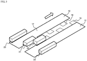
- FIG. 3 is a schematic perspective view illustrating a process of forming an electrode tab in an electrode-processed body of the related art.
- electrode-processed bodies 10 and 11 manufactured through a slitting process are subjected to a notching process for processing shapes of electrode tabs 18 and 19 using a metal mold or a laser.
- the electrode-processed body 10 is cut by metal molds 20, 21, 22, and 23 to process the shapes of the electrode tab 18 and a coated part 17 coated with an electrode mixture.
- an electrode having the shape of the electrode tab is subjected to a process of laminating a separator and a negative electrode and/or a positive electrode, and then laminating the result thereof to manufacture a unit cell. Then, unit cells thus manufactured are placed on, for example, a long separation film, and a folding process is performed to manufacture an electrode assembly.
- the roll-to-roll process refers to a process capable of performing processes such as coating and printing while moving a plurality of bendable metal foils and the like between rollers.
- a roll on which a thin flexible sheet-like material is wound is unwound to supply the material, coating or printing is performed on the supplied material, and the processed material is rewound on another roll.
- FIG. 4 is a schematic plan view of an electrode-processed body having an electrode tab formed by a notching process.
- the non-coated part is folded by a wrinkle or wave pattern formed during the roll-to-roll process, or the wave pattern 15 is formed in some parts of the electrode tab 18 formed on the non-coated part 15 after the notching process of the electrode.
- the electrode tab is easily folded due to wrinkles formed on the electrode tab, resulting failure.
- the present disclosure is provided to solve the above technical problems of the related art.
- the inventors of the present disclosure have conducted intensive researches and various experiments and have found that, as will be described later, in a method of manufacturing an electrode for a secondary battery, before a process of forming electrode strips by slitting a non-coated part in a second direction, when a process of forming non-continuous linear slits in the non-coated part of a metal foil in the second direction is further included, it is possible to prevent wrinkles or wave patterns from being generated and intensified, and also possible to reduce defects due to the folding of the non-coated part or an electrode tab, thereby completing the present disclosure.
- the present disclosure provides a method of manufacturing an electrode for a secondary battery including: a process of continuously forming two or more slurry coated parts on one surface or both surfaces of a metal foil in a second direction which is a longitudinal direction of the metal foil so that a non-coated part which an electrode slurry is not coated is positioned between the slurry coated parts coated with the electrode slurry including an electrode active material in a first direction which is a transverse direction of the metal foil; a process of forming mixture coated parts by drying the slurry coated parts and rolling by a roller; and a process of forming electrode strips by slitting the non-coated part in the second direction.
- the method may further include, before continuously forming the slurry coated parts, while continuously forming the slurry coated parts, or between continuously forming the slurry coated parts and forming the mixture coated parts, a process of forming non-continuous linear slits in the non-coated part of the metal foil in the second direction.
- the method of manufacturing an electrode for a secondary battery can prevent wrinkles or wave patterns generated when a shear force is applied to the non-coated part by a cutter during the slitting process from being further lengthened and intensified by previously performing the process of forming the non-continuous linear slits in the non-coated part of the metal foil in the second direction before continuously forming the slurry coated parts, while continuously forming the slurry coated parts, or between continuously forming the slurry coated parts and forming the mixture coated parts, thereby reducing the folding of the non-coated part or the electrode tab due to the wrinkles or wave patterns.
- the metal foil may be made of one or more selected from the group consisting of stainless steel, aluminum, copper, nickel, titanium, and aluminum alloy.
- the process of forming the non-continuous linear slits may be performed before continuously forming the slurry coated parts. That is, before the electrode slurry including the electrode active material is coated on the metal foil, the non-continuous linear slits may be formed on the non-coated part of the metal foil in the second direction.
- the process of forming the non-continuous linear slits may be performed while continuously forming the slurry coated parts. That is, while the electrode slurry including the electrode active material is being coated on the metal foil, the non-continuous linear slits may be formed on the non-coated part of the metal foil in the second direction.
- the process of forming the non-continuous linear slits may be performed between continuously forming the slurry coated parts and forming the mixture coated parts. That is, after coating the metal foil with the electrode slurry including the electrode active material and before performing the roll press process of drying the slurry coated parts and rolling by a roller, the non-continuous linear slits may be formed on the non-coated part of the metal foil in the second direction.
- the non-continuous linear slits may be formed perpendicular to the first direction, in particular, the non-continuous linear slits may be formed in a direction coinciding with a direction of slitting in the process of forming the electrode strips.
- a length of each of the non-continuous linear slits may be in a range of about 1 to 200mm, in particular, when the length is less than 1mm, it may be difficult to exhibit an effect required by the present disclosure, when the length is more than 200mm, the non-coated part of the metal foil may be separated during transportation, which may make handling difficult.
- an interval between the non-continuous linear slits may be in a range of about 1 to 1000mm.
- the interval between the linear slits may be so small that the non-coated part of the metal foil may be separated during transportation, which may make handling difficult, and when the interval is more than 1000mm, it may be difficult to exhibit an effect required by the present disclosure.
- the slitting of the non-coated part may be performed by cutting between the non-continuous linear slits, and more specifically, a cutter for slitting may move in the second direction which is the longitudinal direction of the metal foil, thereby cutting between the linear slits.
- a notching process of forming the electrode tab by partially cutting the slit non-coated part of the electrode strip may be further included.
- a cutting process of forming a unit electrode by cutting the electrode strip uniformly in the first direction may be further included.
- the present disclosure also provides an electrode for a secondary battery manufactured according to the method of manufacturing the electrode for a secondary battery.
- the present disclosure also provides a lithium secondary battery including the electrode for a secondary battery.
- the lithium secondary battery may have a structure in which an electrode assembly including a negative electrode, a positive electrode and a separator interposed between the negative electrode and the positive electrode are embedded together with a nonaqueous electrolyte solution in a pouch-shaped battery case.
- the pouch-shaped battery case may be made of a laminated sheet including an outer resin layer made of a polymer resin having weather resistance, a metal layer having gas and liquid barrier properties, and an inner resin layer made of a polymer resin having thermal fusion properties, and the battery cell may be plate-shaped with a rectangular parallelepiped structure of a small thickness with respect to the width.
- the positive electrode may be manufactured, for example, by coating a mixture of a positive electrode active material, a conductive material and a binder on a positive electrode current collector and drying. If necessary, a filler may be further added to the mixture.
- the positive electrode active material may be a material capable of causing an electrochemical reaction, and may be a lithium transition metal oxide and may include two or more transition metals.
- Examples of the positive electrode active material may include layered compounds such as lithium cobalt oxide (LiCoO 2 ) substituted with one or more transition metals, lithium nickel oxide (LiNiO 2 ); lithium manganese oxides substituted with one or more transition metals; lithium nickel-based oxides having formula LiNi 1-y M y O 2 (wherein, M includes one or more elements selected from the group consisting of Co, Mn, Al, Cu, Fe, Mg, B, Cr, Zn or Ga, and 0.01 ⁇ x ⁇ 0.7); lithium nickel cobalt manganese composite oxides having formula Li 1+z Ni b Mn c Co 1-(b+c+d) M d O (2-e) A e such as Li 1+z Ni 1/3 Co 1/3 Mn 1/3 O 2 and Li 1+z Ni 0.4 Mn 0.4 Co 0.2 O 2 (wherein
- the conductive material may be generally added in an amount of 1 to 20wt% based on the total weight of a mixture including a positive electrode active material.
- the conductive material there is no particular limit as to the conductive material, so long as it does not cause chemical changes in the fabricated battery and has conductivity.
- graphite such as natural or artificial graphite
- carbon black such as carbon black, acetylene black, ketjen black, channel black, furnace black, lamp black, and thermal black
- conductive fibers such as carbon fiber and metallic fiber
- metallic powders such as carbon fluoride powder, aluminum powder, and nickel powder
- conductive whiskers such as zinc oxide whiskers and potassium titanate whiskers
- conductive metal oxides such as titanium oxide
- conductive materials such as polyphenylene derivatives; and etc.
- the filler may be optionally used as a component to inhibit positive electrode expansion.
- the filler is not particularly limited so long as it is a fibrous material that does not cause chemical changes in the fabricated battery.
- examples of the filler include olefin-based polymers such as polyethylene and polypropylene; and fibrous materials such as glass fiber and carbon fiber.
- the negative electrode may be manufactured by coating and drying a mixture of a negative electrode active material, a conductive material a binder on a negative electrode current collector. As desired, a filler may be further added to the mixture.
- the negative electrode active material may be one or more selected from the group consisting of graphite carbon, coke-based carbon and hard carbon.
- the present disclosure also provides a battery pack including the lithium secondary battery as a unit cell.
- the present disclosure also provides a device including the battery pack.
- Examples of the device include mobile phones, portable computers, wearable electronic devices, tablet PCs, smart pads, netbooks, LEV (Light Electronic Vehicle), electric vehicles, hybrid electric vehicles and power storage devices, but are not limited thereto.
- LEV Light Electronic Vehicle
- the method of manufacturing the electrode for a secondary battery according to the present disclosure can prevent wrinkles or wave patterns generated when a shear force is applied to the non-coated part by a cutter during the slitting process from being longer and deeper by previously performing the process of forming non-continuous linear slits in the non-coated part of the metal foil in the second direction before continuously forming the slurry coated parts, while continuously forming the slurry coated parts, or between continuously forming the slurry coated parts and forming the mixture coated parts, thereby reducing defects due to the folding of the non-coated part or the electrode tab.
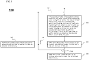
- FIG. 5 is a flowchart illustrating a process of manufacturing an electrode for a secondary battery according to an exemplary embodiment of the present disclosure
- FIG. 6 is a schematic plan view of a metal foil before a process 110 is performed in a method of manufacturing an electrode for a secondary battery according to an exemplary embodiment of the present disclosure
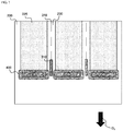
- FIG. 7 is a schematic plan view of a metal foil while the process 110 is performed in a method of manufacturing an electrode for a secondary battery according to another exemplary embodiment of the present disclosure.
- a method 100 of manufacturing an electrode for a secondary battery may include a process 110 of continuously forming three slurry coated parts 220, 221, and 222 on one surface or both surfaces of a metal foil 200 in a second direction D 2 , which is a longitudinal direction of the metal foil 200, so that a non-coated part 230, which is not coated with an electrode slurry, is positioned between the slurry coated parts 220, 221, and 222 coated with an electrode slurry 225 including an electrode active material in a first direction D 1 , which is a transverse direction of the metal foil 200, a process 120 of forming mixture coated parts 204 ( FIG.
- the metal foil 200 may be made of aluminum when a positive electrode current collector is manufactured, and copper may be used as the metal foil 200 when a negative electrode current collector is manufactured.
- a process 140 of forming non-continuous linear slits 210 in the non-coated part 230 of the metal foil 200 in the second direction D 2 by a cutter member 310 may be performed before the process 110 of coating the metal foil 200 with the electrode slurry (not shown) including the electrode active material.
- non-continuous linear slits 210 may be formed perpendicular to the first direction D 1 , and the non-continuous linear slits 210 may also be formed in a direction coinciding with the second direction D 2 of slitting in the process 130.
- a length L 1 of each of the non-continuous linear slits 210 may be in a range of about 1 to 200 mm, and an interval L 2 between the non-continuous linear slits 210 may be in a range of about 1 to 1,000 mm.
- the process 140 of forming non-continuous linear slits 210 in the non-coated part 230 of the metal foil 200 in the second direction D 2 by a cutter member 310 may be performed during the process 110 of coating the metal foil 200 with the electrode slurry 225 including the electrode active material by a discharge member 400.
- FIG. 8 is a schematic plan view of a metal foil between the process 110 and the process 120 in a method of manufacturing an electrode for a secondary battery according to still another exemplary embodiment of the present disclosure.
- the process 140 of forming the non-continuous linear slits 210 in the non-coated part 230 of the metal foil 200 in the second direction D 2 may be performed between the process 110 of coating the metal foil 200 with the electrode slurry 225 including the electrode active material and the process 120 of performing a roll press process of rolling and drying the slurry coated parts 220, 221 and 222 by rollers 501 and 502.
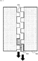
- FIG. 9 is a schematic plan view illustrating the process 130 in a method of manufacturing an electrode for a secondary battery according to an exemplary embodiment of the present disclosure.
- the slitting of the non-coated part 230 may be performed by cutting between the non-continuous linear slits 210 by a cutter 300 for slitting moving in the second direction D 2 , which is the longitudinal direction of the metal foil 200.
- FIG. 10 is a schematic plan view illustrating a notching process of forming an electrode tab in a method of manufacturing an electrode for a secondary battery according to an exemplary embodiment of the present disclosure.
- a notching process of forming electrode tabs 232 by partially cutting the slit non-coated part 230 of the electrode strip 260 using a metal mold 600 is further performed.
- FIG. 11 is a schematic plan view illustrating a cutting process of forming a unit electrode in a method of manufacturing an electrode for a secondary battery according to an exemplary embodiment of the present disclosure.
- a cutting process of forming a unit electrode 700 by cutting the electrode strip 260 uniformly in the first direction D 1 using a cutter 330 is further performed after the notching process of FIG. 10 .
- the method of manufacturing an electrode for a secondary battery according to the present disclosure can prevent wrinkles or wave patterns, which are generated when a shear force is applied to a non-coated part by a cutter during a slitting process, from being further lengthened or deepened by performing a process of forming non-continuous linear slits in the non-coated part of a metal foil in a second direction before a process of continuously forming slurry coated parts, during a process of continuously forming the slurry coated parts, or between the processes of continuously forming the slurry coated parts and forming the slurry coated parts, thereby reducing defects due to folding of the non-coated part or an electrode tab by the wrinkles or wave patterns.
Landscapes
- Chemical & Material Sciences (AREA)
- Engineering & Computer Science (AREA)
- General Chemical & Material Sciences (AREA)
- Chemical Kinetics & Catalysis (AREA)
- Electrochemistry (AREA)
- Manufacturing & Machinery (AREA)
- Materials Engineering (AREA)
- Dispersion Chemistry (AREA)
- Life Sciences & Earth Sciences (AREA)
- Forests & Forestry (AREA)
- Mechanical Engineering (AREA)
- Battery Electrode And Active Subsutance (AREA)
- Cell Electrode Carriers And Collectors (AREA)
Abstract
Description
- The present disclosure relates to a method of manufacturing an electrode for a secondary battery including a pre-slitting process.
- Recent trends in the development of the electronic industry can be summarized as wireless functions of a device, a mobile trend, and a transition from analog to digital. The rapid dissemination of wireless phones (so-called mobile phones) and notebook computers, and the transition from analog cameras to digital cameras may be referred to as representative examples of such trends.
- Along with this tendency, research and development on secondary batteries as an operating power source of a device have been actively proceeding. Among such secondary batteries, a lithium secondary battery having a great output and capacity in comparison to its weight and using a lithium transition metal oxide, a lithium composite oxide, and the like as a positive electrode active material has received particular attention. The lithium secondary battery has a structure in which an electrode assembly of a positive electrode/a separator/a negative electrode is embedded in a sealed container together with an electrolyte.
- Meanwhile, an electrode generate current via the exchanges of ions, and a positive electrode and a negative electrode constituting the electrode have a structure in which an electrode active material is applied to an electrode current collector made of metal.
- Generally, the negative electrode has a structure in which a carbon-based active material is applied to an electrode plate made of copper, aluminum, and the like, and the positive electrode has a structure in which an active material made of LiCoO2, LiMnO2, LiNiO2 and the like is coated on an electrode plate made of aluminum and the like.
- In order to manufacture the positive electrode or the negative electrode, an electrode mixture including an electrode active material is applied to an electrode current collector made of a metal sheet which is elongated in one direction.
-
FIG. 1 is a schematic plan view in which a roll press process is performed on an electrode-processed body to which an electrode mixture of the related art is applied. - Referring to
FIG. 1 , through the roll press process, heatedrollers body 10 on which anelectrode slurry 14 including an electrode active material is applied, and the heatedrollers electrode slurry 14 in a direction of the electrode-processedbody 10. In the roll press process, a solvent remaining in the electrode slurry is evaporated, and the electrode slurry is compressed and cured on the electrode to form an electrode mixture layer having improved energy density. Thereafter, a process for processing an outer shape of a set electrode is performed. -
FIG. 2 is a schematic plan view illustrating a process of slitting an electrode-processed body of the related art. - Referring to
FIG. 2 , an electrode current collector coated with theelectrode mixture 14, made of a metal sheet which is elongated in one direction D2 is slit using acutter 20, and the electrode current collector is divided into electrode strips. - In particular, a first direction D1 is a transverse direction of a metal foil, and the second direction D2 is a longitudinal direction of the metal foil.
-
FIG. 3 is a schematic perspective view illustrating a process of forming an electrode tab in an electrode-processed body of the related art. - Referring to
FIG. 3 , electrode-processedbodies electrode tabs body 10 is cut bymetal molds electrode tab 18 and a coatedpart 17 coated with an electrode mixture. - Thereafter, an electrode having the shape of the electrode tab is subjected to a process of laminating a separator and a negative electrode and/or a positive electrode, and then laminating the result thereof to manufacture a unit cell. Then, unit cells thus manufactured are placed on, for example, a long separation film, and a folding process is performed to manufacture an electrode assembly.
- Most of the roll press process, the slitting process, the notching process, the lamination process, and the folding process described above use a roll-to-roll process, and the roll-to-roll process refers to a process capable of performing processes such as coating and printing while moving a plurality of bendable metal foils and the like between rollers. For example, there is a method in which a roll on which a thin flexible sheet-like material is wound is unwound to supply the material, coating or printing is performed on the supplied material, and the processed material is rewound on another roll.
-
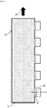
FIG. 4 is a schematic plan view of an electrode-processed body having an electrode tab formed by a notching process. - Referring to
FIGS. 1 ,2 , and3 together, in the electrode manufacturing method of the related art, when the roll press process of the electrode-processedbody 10 coated with the electrode mixture is performed, a difference in elongation between the coatedpart 17 coated with the electrode mixture and thenon-coated part 18 only with a metal foil and not being coated with the electrode mixture occurs so that, in the non-coated part, awave pattern 15 is generated near a boundary with the coated part. Further, after the roll press process, when a shear force is applied to the non-coated part by a cutter during the slitting process, the previously generated wrinkles or wave pattern becomes longer and deeper. - Because of this, in the process of manufacturing the electrode, the non-coated part is folded by a wrinkle or wave pattern formed during the roll-to-roll process, or the
wave pattern 15 is formed in some parts of theelectrode tab 18 formed on the non-coatedpart 15 after the notching process of the electrode. As a result, when external interference occurs at the electrode tab, there is a problem in that the electrode tab is easily folded due to wrinkles formed on the electrode tab, resulting failure. - Therefore, development of technology capable of reducing defects caused by folding of a non-coated part or an electrode tab due to wrinkles or patterns generated during the process of manufacturing an electrode of a secondary battery is in demand.
- The present disclosure is provided to solve the above technical problems of the related art.
- The inventors of the present disclosure have conducted intensive researches and various experiments and have found that, as will be described later, in a method of manufacturing an electrode for a secondary battery, before a process of forming electrode strips by slitting a non-coated part in a second direction, when a process of forming non-continuous linear slits in the non-coated part of a metal foil in the second direction is further included, it is possible to prevent wrinkles or wave patterns from being generated and intensified, and also possible to reduce defects due to the folding of the non-coated part or an electrode tab, thereby completing the present disclosure.
- The present disclosure provides a method of manufacturing an electrode for a secondary battery including:
a process of continuously forming two or more slurry coated parts on one surface or both surfaces of a metal foil in a second direction which is a longitudinal direction of the metal foil so that a non-coated part which an electrode slurry is not coated is positioned between the slurry coated parts coated with the electrode slurry including an electrode active material in a first direction which is a transverse direction of the metal foil; a process of forming mixture coated parts by drying the slurry coated parts and rolling by a roller; and a process of forming electrode strips by slitting the non-coated part in the second direction. - The method may further include, before continuously forming the slurry coated parts, while continuously forming the slurry coated parts, or between continuously forming the slurry coated parts and forming the mixture coated parts, a process of forming non-continuous linear slits in the non-coated part of the metal foil in the second direction.
- Therefore, the method of manufacturing an electrode for a secondary battery can prevent wrinkles or wave patterns generated when a shear force is applied to the non-coated part by a cutter during the slitting process from being further lengthened and intensified by previously performing the process of forming the non-continuous linear slits in the non-coated part of the metal foil in the second direction before continuously forming the slurry coated parts, while continuously forming the slurry coated parts, or between continuously forming the slurry coated parts and forming the mixture coated parts, thereby reducing the folding of the non-coated part or the electrode tab due to the wrinkles or wave patterns.
- In an exemplary embodiment, the metal foil may be made of one or more selected from the group consisting of stainless steel, aluminum, copper, nickel, titanium, and aluminum alloy.
- In an exemplary embodiment, the process of forming the non-continuous linear slits may be performed before continuously forming the slurry coated parts. That is, before the electrode slurry including the electrode active material is coated on the metal foil, the non-continuous linear slits may be formed on the non-coated part of the metal foil in the second direction.
- In another exemplary embodiment, the process of forming the non-continuous linear slits may be performed while continuously forming the slurry coated parts. That is, while the electrode slurry including the electrode active material is being coated on the metal foil, the non-continuous linear slits may be formed on the non-coated part of the metal foil in the second direction.
- In another exemplary embodiment, the process of forming the non-continuous linear slits may be performed between continuously forming the slurry coated parts and forming the mixture coated parts. That is, after coating the metal foil with the electrode slurry including the electrode active material and before performing the roll press process of drying the slurry coated parts and rolling by a roller, the non-continuous linear slits may be formed on the non-coated part of the metal foil in the second direction.
- In an exemplary embodiment, the non-continuous linear slits may be formed perpendicular to the first direction, in particular, the non-continuous linear slits may be formed in a direction coinciding with a direction of slitting in the process of forming the electrode strips.
- In addition, a length of each of the non-continuous linear slits may be in a range of about 1 to 200mm, in particular, when the length is less than 1mm, it may be difficult to exhibit an effect required by the present disclosure, when the length is more than 200mm, the non-coated part of the metal foil may be separated during transportation, which may make handling difficult.
- Further, an interval between the non-continuous linear slits may be in a range of about 1 to 1000mm. When the interval is less than 1mm, the interval between the linear slits may be so small that the non-coated part of the metal foil may be separated during transportation, which may make handling difficult, and when the interval is more than 1000mm, it may be difficult to exhibit an effect required by the present disclosure.
- In an exemplary embodiment, in the process of forming the electrode strips, the slitting of the non-coated part may be performed by cutting between the non-continuous linear slits, and more specifically, a cutter for slitting may move in the second direction which is the longitudinal direction of the metal foil, thereby cutting between the linear slits.
- In an exemplary embodiment, after the process of forming the electrode strips, a notching process of forming the electrode tab by partially cutting the slit non-coated part of the electrode strip may be further included.
- In addition, after the notching process, a cutting process of forming a unit electrode by cutting the electrode strip uniformly in the first direction may be further included.
- Since devices used to manufacture the electrode for a secondary battery are well known in the art, detailed description thereof will be omitted herein.
- The present disclosure also provides an electrode for a secondary battery manufactured according to the method of manufacturing the electrode for a secondary battery.
- The present disclosure also provides a lithium secondary battery including the electrode for a secondary battery.
- In particular, the lithium secondary battery may have a structure in which an electrode assembly including a negative electrode, a positive electrode and a separator interposed between the negative electrode and the positive electrode are embedded together with a nonaqueous electrolyte solution in a pouch-shaped battery case.
- Also, the pouch-shaped battery case may be made of a laminated sheet including an outer resin layer made of a polymer resin having weather resistance, a metal layer having gas and liquid barrier properties, and an inner resin layer made of a polymer resin having thermal fusion properties, and the battery cell may be plate-shaped with a rectangular parallelepiped structure of a small thickness with respect to the width.
- The positive electrode may be manufactured, for example, by coating a mixture of a positive electrode active material, a conductive material and a binder on a positive electrode current collector and drying. If necessary, a filler may be further added to the mixture.
- The positive electrode active material may be a material capable of causing an electrochemical reaction, and may be a lithium transition metal oxide and may include two or more transition metals. Examples of the positive electrode active material may include layered compounds such as lithium cobalt oxide (LiCoO2) substituted with one or more transition metals, lithium nickel oxide (LiNiO2); lithium manganese oxides substituted with one or more transition metals; lithium nickel-based oxides having formula LiNi1-yMyO2 (wherein, M includes one or more elements selected from the group consisting of Co, Mn, Al, Cu, Fe, Mg, B, Cr, Zn or Ga, and 0.01 ≦ x ≦ 0.7); lithium nickel cobalt manganese composite oxides having formula Li1+zNibMncCo1-(b+c+d)MdO(2-e)Ae such as Li1+zNi1/3Co1/3Mn1/3O2 and Li1+zNi0.4Mn0.4Co0.2O2 (wherein, -0.5≤z≤0.5, 0.1≤b≤0.8, 0.1≤c≤0.8, 0≤d≤0.2, 0≤e≤0.2, b+c+d<1, M = Al, Mg, Cr, Ti, Si or Y and A = F, P or CI); Olivine-based lithium metal phosphates having formula Li1+xM1-yM'yP04-zXz (wherein, M is a transition metal, preferably M = Fe, Mn, Co or Ni, M'= Al, Mg or Ti, X = F, S or N, -0.5≤x≤+0.5, 0≤y≤0.5 and 0≤z≤0.1); and the like, but embodiments of the present disclosure are not limited thereto.
- The conductive material may be generally added in an amount of 1 to 20wt% based on the total weight of a mixture including a positive electrode active material. There is no particular limit as to the conductive material, so long as it does not cause chemical changes in the fabricated battery and has conductivity. For example, graphite such as natural or artificial graphite; carbon black such as carbon black, acetylene black, ketjen black, channel black, furnace black, lamp black, and thermal black; conductive fibers such as carbon fiber and metallic fiber; metallic powders such as carbon fluoride powder, aluminum powder, and nickel powder; conductive whiskers such as zinc oxide whiskers and potassium titanate whiskers; conductive metal oxides such as titanium oxide; conductive materials such as polyphenylene derivatives; and etc. may be used.
- The filler may be optionally used as a component to inhibit positive electrode expansion. The filler is not particularly limited so long as it is a fibrous material that does not cause chemical changes in the fabricated battery. Examples of the filler include olefin-based polymers such as polyethylene and polypropylene; and fibrous materials such as glass fiber and carbon fiber.
- In addition, the negative electrode may be manufactured by coating and drying a mixture of a negative electrode active material, a conductive material a binder on a negative electrode current collector. As desired, a filler may be further added to the mixture. Also, the negative electrode active material may be one or more selected from the group consisting of graphite carbon, coke-based carbon and hard carbon.
- The present disclosure also provides a battery pack including the lithium secondary battery as a unit cell.
- The present disclosure also provides a device including the battery pack. Examples of the device include mobile phones, portable computers, wearable electronic devices, tablet PCs, smart pads, netbooks, LEV (Light Electronic Vehicle), electric vehicles, hybrid electric vehicles and power storage devices, but are not limited thereto.
- Since the structure and manufacturing method of the device are well known in the art, detailed description thereof will be omitted herein.
- As described above, the method of manufacturing the electrode for a secondary battery according to the present disclosure can prevent wrinkles or wave patterns generated when a shear force is applied to the non-coated part by a cutter during the slitting process from being longer and deeper by previously performing the process of forming non-continuous linear slits in the non-coated part of the metal foil in the second direction before continuously forming the slurry coated parts, while continuously forming the slurry coated parts, or between continuously forming the slurry coated parts and forming the mixture coated parts, thereby reducing defects due to the folding of the non-coated part or the electrode tab.
-
-
FIG. 1 is a schematic plan view in which a roll press process is performed on an electrode-processed body to which an electrode mixture of the related art is applied. -
FIG. 2 is a schematic plan view illustrating a process of slitting an electrode-processed body of the related art. -
FIG. 3 is a schematic perspective view illustrating a process of forming an electrode tab in an electrode-processed body of the related art. -
FIG. 4 is a schematic plan view of an electrode-processed body having an electrode tab formed by a notching process of the related art. -
FIG. 5 is a flowchart illustrating a process of manufacturing an electrode for a secondary battery according to an exemplary embodiment of the present disclosure. -
FIG. 6 is a schematic plan view of a metal foil before aprocess 110 is performed in a method of manufacturing an electrode for a secondary battery according to an exemplary embodiment of the present disclosure. -
FIG. 7 is a schematic plan view of a metal foil while aprocess 110 is being performed in a method of manufacturing an electrode for a secondary battery according to another exemplary embodiment of the present disclosure. -
FIG. 8 is a schematic plan view of a metal foil between aprocess 110 and aprocess 120 in a method of manufacturing an electrode for a secondary battery according to still another exemplary embodiment of the present disclosure. -
FIG. 9 is a schematic plan view illustrating aprocess 130 in a method of manufacturing an electrode for a secondary battery according to an exemplary embodiment of the present disclosure. -
FIG. 10 is a schematic plan view illustrating a notching process of forming an electrode tab in a method of manufacturing an electrode for a secondary battery according to an exemplary embodiment of the present disclosure. -
FIG. 11 is a schematic plan view illustrating a cutting process of forming a unit electrode in a method of manufacturing an electrode for a secondary battery according to an exemplary embodiment of the present disclosure. - Hereinafter, embodiments of the present disclosure will be described with reference to the accompanying drawings. However, the description provided herein is for a better understanding of the present disclosure, and the scope of the present disclosure is not limited thereto.
-
FIG. 5 is a flowchart illustrating a process of manufacturing an electrode for a secondary battery according to an exemplary embodiment of the present disclosure,FIG. 6 is a schematic plan view of a metal foil before aprocess 110 is performed in a method of manufacturing an electrode for a secondary battery according to an exemplary embodiment of the present disclosure, andFIG. 7 is a schematic plan view of a metal foil while theprocess 110 is performed in a method of manufacturing an electrode for a secondary battery according to another exemplary embodiment of the present disclosure. - Referring to
FIG. 5 to FIG. 7 , amethod 100 of manufacturing an electrode for a secondary battery according to the present disclosure may include aprocess 110 of continuously forming three slurry coatedparts metal foil 200 in a second direction D2, which is a longitudinal direction of themetal foil 200, so that anon-coated part 230, which is not coated with an electrode slurry, is positioned between the slurry coatedparts electrode slurry 225 including an electrode active material in a first direction D1, which is a transverse direction of themetal foil 200, aprocess 120 of forming mixture coated parts 204 (FIG. 9 ) by rolling and drying the slurry coatedparts process 130 of forming electrode strips 260 (FIG. 10 ) by slitting thenon-coated part 230 in the second direction D2. - In particular, the
metal foil 200 may be made of aluminum when a positive electrode current collector is manufactured, and copper may be used as themetal foil 200 when a negative electrode current collector is manufactured. - Referring to
FIG. 5 andFIG.6 , aprocess 140 of forming non-continuouslinear slits 210 in thenon-coated part 230 of themetal foil 200 in the second direction D2 by acutter member 310 may be performed before theprocess 110 of coating themetal foil 200 with the electrode slurry (not shown) including the electrode active material. - In addition, the non-continuous
linear slits 210 may be formed perpendicular to the first direction D1, and the non-continuouslinear slits 210 may also be formed in a direction coinciding with the second direction D2 of slitting in theprocess 130. - Further, a length L1 of each of the non-continuous
linear slits 210 may be in a range of about 1 to 200 mm, and an interval L2 between the non-continuouslinear slits 210 may be in a range of about 1 to 1,000 mm. - Referring to
FIG. 5 andFIG. 7 , in the process of forming the non-continuouslinear slits 210, theprocess 140 of forming non-continuouslinear slits 210 in thenon-coated part 230 of themetal foil 200 in the second direction D2 by acutter member 310 may be performed during theprocess 110 of coating themetal foil 200 with theelectrode slurry 225 including the electrode active material by adischarge member 400. -
FIG. 8 is a schematic plan view of a metal foil between theprocess 110 and theprocess 120 in a method of manufacturing an electrode for a secondary battery according to still another exemplary embodiment of the present disclosure. - Referring to
FIG. 5 andFIG. 8 , theprocess 140 of forming the non-continuouslinear slits 210 in thenon-coated part 230 of themetal foil 200 in the second direction D2 may be performed between theprocess 110 of coating themetal foil 200 with theelectrode slurry 225 including the electrode active material and theprocess 120 of performing a roll press process of rolling and drying the slurry coatedparts rollers -
FIG. 9 is a schematic plan view illustrating theprocess 130 in a method of manufacturing an electrode for a secondary battery according to an exemplary embodiment of the present disclosure. - Referring to
FIGS. 5 and9 , in theprocess 130, the slitting of thenon-coated part 230 may be performed by cutting between the non-continuouslinear slits 210 by acutter 300 for slitting moving in the second direction D2, which is the longitudinal direction of themetal foil 200. -
FIG. 10 is a schematic plan view illustrating a notching process of forming an electrode tab in a method of manufacturing an electrode for a secondary battery according to an exemplary embodiment of the present disclosure. - Referring to
FIGS. 5 ,9 and10 , in the method of manufacturing an electrode for a secondary battery according to an exemplary embodiment of the present disclosure, after theprocess 130, a notching process of formingelectrode tabs 232 by partially cutting the slitnon-coated part 230 of theelectrode strip 260 using ametal mold 600 is further performed. -
FIG. 11 is a schematic plan view illustrating a cutting process of forming a unit electrode in a method of manufacturing an electrode for a secondary battery according to an exemplary embodiment of the present disclosure. - Referring to
FIG. 10 andFIG. 11 , in the method of manufacturing an electrode for a secondary battery according to an exemplary embodiment of the present disclosure, a cutting process of forming aunit electrode 700 by cutting theelectrode strip 260 uniformly in the first direction D1 using acutter 330 is further performed after the notching process ofFIG. 10 . - As described above, the method of manufacturing an electrode for a secondary battery according to the present disclosure can prevent wrinkles or wave patterns, which are generated when a shear force is applied to a non-coated part by a cutter during a slitting process, from being further lengthened or deepened by performing a process of forming non-continuous linear slits in the non-coated part of a metal foil in a second direction before a process of continuously forming slurry coated parts, during a process of continuously forming the slurry coated parts, or between the processes of continuously forming the slurry coated parts and forming the slurry coated parts, thereby reducing defects due to folding of the non-coated part or an electrode tab by the wrinkles or wave patterns.
Claims (12)
- A method of manufacturing an electrode for a secondary battery, the method comprising:a process of continuously forming two or more slurry coated parts on one surface or both surfaces of a metal foil in a second direction which is a longitudinal direction of the metal foil so that a non-coated part which an electrode slurry is not coated is positioned between the slurry coated parts coated with the electrode slurry including an electrode active material in a first direction which is a transverse direction of the metal foil;a process of forming mixture coated parts by drying the slurry coated parts and rolling by a roller; anda process of forming electrode strips by slitting the non-coated part in the second direction,wherein, before continuously forming the slurry coated parts, while continuously forming the slurry coated parts, or between continuously forming the slurry coated parts and forming the mixture coated parts, the method further comprises a process of forming non-continuous linear slits in the non-coated part of the metal foil in the second direction.
- The method of manufacturing an electrode for a secondary battery according to claim 1, wherein the metal foil is made of one or more selected from the group consisting of stainless steel, aluminum, copper, nickel, titanium, and an aluminum alloy.
- The method of manufacturing an electrode for a secondary battery according to claim 1, wherein the process of forming the non-continuous linear slits is performed before continuously forming the slurry coated parts.
- The method of manufacturing an electrode for a secondary battery according to claim 1, wherein the process of forming the non-continuous linear slits is performed while continuously forming the slurry coated parts.
- The method of manufacturing an electrode for a secondary battery according to claim 1, wherein the process of forming the non-continuous linear slits is performed between continuously forming the slurry coated parts and forming the mixture coated parts.
- The method of manufacturing an electrode for a secondary battery according to claim 1, wherein a length of each of the non-continuous linear slits is in a range of about 1 to 200mm.
- The method of manufacturing an electrode for a secondary battery according to claim 1, wherein an interval between the non-continuous linear slits is in a range of about 1 to 1000mm.
- The method of manufacturing an electrode for a secondary battery according to claim 1, wherein the non-continuous linear slits are formed perpendicular to the first direction.
- The method of manufacturing an electrode for a secondary battery according to claim 1, wherein, in the process of forming the electrode strips, the slitting of the non-coated part is performed by cutting between the non-continuous linear slits.
- The method of manufacturing an electrode for a secondary battery according to claim 1, wherein, after the process of forming the electrode strips, a notching process of forming the electrode tab by partially cutting the slit non-coated part of the electrode strip is further included.
- The method of manufacturing an electrode for a secondary battery according to claim 10, wherein, after the notching process, a cutting process of forming a unit electrode by cutting the electrode strip uniformly in the second direction is further included.
- An electrode for a secondary battery manufactured according to the method of manufacturing the electrode for a secondary battery of claim 1.
Applications Claiming Priority (2)
| Application Number | Priority Date | Filing Date | Title |
|---|---|---|---|
| KR1020160130087A KR102162773B1 (en) | 2016-10-07 | 2016-10-07 | Method for Manufacturing Electrode for Secondary Battery Comprising Pre-Slitting Process |
| PCT/KR2017/008719 WO2018066806A1 (en) | 2016-10-07 | 2017-08-11 | Method for manufacturing secondary battery electrode comprising pre-slitting process |
Publications (3)
| Publication Number | Publication Date |
|---|---|
| EP3404745A1 true EP3404745A1 (en) | 2018-11-21 |
| EP3404745A4 EP3404745A4 (en) | 2019-05-08 |
| EP3404745B1 EP3404745B1 (en) | 2020-09-30 |
Family
ID=61831443
Family Applications (1)
| Application Number | Title | Priority Date | Filing Date |
|---|---|---|---|
| EP17858601.2A Active EP3404745B1 (en) | 2016-10-07 | 2017-08-11 | Method for manufacturing secondary battery electrode comprising pre-slitting process |
Country Status (5)
| Country | Link |
|---|---|
| US (1) | US11329272B2 (en) |
| EP (1) | EP3404745B1 (en) |
| KR (1) | KR102162773B1 (en) |
| CN (1) | CN108604669B (en) |
| WO (1) | WO2018066806A1 (en) |
Cited By (6)
| Publication number | Priority date | Publication date | Assignee | Title |
|---|---|---|---|---|
| CN113711380A (en) * | 2019-05-09 | 2021-11-26 | 株式会社Lg新能源 | Electrode and method for producing the same |
| US11594713B2 (en) | 2018-05-23 | 2023-02-28 | Lg Energy Solution, Ltd. | Notching apparatus and method for secondary battery |
| WO2023158215A1 (en) * | 2022-02-15 | 2023-08-24 | 주식회사 엘지에너지솔루션 | Secondary battery manufacturing device and secondary battery manufacturing method using same |
| IT202200018948A1 (en) | 2022-09-15 | 2024-03-15 | P I T S R L | METHOD AND EQUIPMENT FOR SHAPED CUTTING OF STRIP MATERIAL |
| IT202200018960A1 (en) | 2022-09-15 | 2024-03-15 | P I T S R L | METHOD AND EQUIPMENT FOR SHAPED CUTTING OF STRIP MATERIAL |
| DE102024126118A1 (en) | 2024-07-25 | 2026-01-29 | GM Global Technology Operations LLC | Manufacturing process for staggered electrode tabs with high throughput |
Families Citing this family (14)
| Publication number | Priority date | Publication date | Assignee | Title |
|---|---|---|---|---|
| DE102019100476A1 (en) * | 2019-01-10 | 2020-07-16 | Bayerische Motoren Werke Aktiengesellschaft | Collector foil and method for producing a collector foil |
| KR102757189B1 (en) * | 2019-03-28 | 2025-01-21 | 주식회사 엘지에너지솔루션 | Electrode manufacturing equipment for rechargeable battery, electrode manufactured from thereof and rechargeable battery |
| CN110165145A (en) * | 2019-05-13 | 2019-08-23 | 无锡先导智能装备股份有限公司 | Pole piece pretreatment of base material method and pole piece substrate |
| KR102446291B1 (en) * | 2019-10-31 | 2022-09-22 | 삼성에스디아이 주식회사 | Electrode plate manufacturing method and electrode plate manufactured through the same |
| CN113394366B (en) * | 2021-06-11 | 2022-06-28 | 四川无量智慧道桥科技有限公司 | Production process and system of high-precision lithium battery pole piece |
| KR102667004B1 (en) * | 2021-10-14 | 2024-05-17 | 유일에너테크(주) | System for producing electrodes of battery |
| KR20230063105A (en) * | 2021-11-01 | 2023-05-09 | 주식회사 엘지에너지솔루션 | Simulation method and device for secondary battery production |
| KR20230074969A (en) * | 2021-11-22 | 2023-05-31 | 주식회사 엘지에너지솔루션 | Coater simulation test method and device for secondary battery production |
| KR20230074973A (en) * | 2021-11-22 | 2023-05-31 | 주식회사 엘지에너지솔루션 | Coater simulation method and device for secondary battery production |
| CN116799324A (en) * | 2022-03-18 | 2023-09-22 | 宁德时代新能源科技股份有限公司 | Winding equipment and methods |
| CN115332542B (en) * | 2022-10-12 | 2023-04-07 | 楚能新能源股份有限公司 | Battery core pole piece substrate and pole piece production equipment |
| CN120418966A (en) * | 2023-09-05 | 2025-08-01 | 株式会社Lg新能源 | Method for manufacturing positive electrode, and lithium secondary battery comprising same |
| US12494471B2 (en) | 2023-12-08 | 2025-12-09 | Enovix Corporation | Mechanical stripping of sacrificial layer |
| KR102817647B1 (en) * | 2024-05-23 | 2025-06-10 | 주식회사 피엔티머티리얼즈 | Electrode assembly, electrode plate, secondary battery, electrode plate manufacturing method for secondary battery |
Family Cites Families (20)
| Publication number | Priority date | Publication date | Assignee | Title |
|---|---|---|---|---|
| US5411592A (en) * | 1994-06-06 | 1995-05-02 | Ovonic Battery Company, Inc. | Apparatus for deposition of thin-film, solid state batteries |
| KR100450178B1 (en) | 1997-08-06 | 2004-11-26 | 삼성에스디아이 주식회사 | Manufacturing Method of Lithium Polymer Series Battery |
| JP2000208129A (en) * | 1999-01-13 | 2000-07-28 | Ngk Insulators Ltd | Lithium secondary battery |
| JP2002237292A (en) * | 2001-02-09 | 2002-08-23 | Japan Storage Battery Co Ltd | Non-aqueous electrolyte secondary battery |
| JP2008066050A (en) * | 2006-09-06 | 2008-03-21 | Matsushita Electric Ind Co Ltd | Method for producing electrode plate for lithium secondary battery |
| KR20080058772A (en) | 2006-12-22 | 2008-06-26 | 에스케이에너지 주식회사 | Manufacturing Method of Battery Electrode |
| KR101192056B1 (en) * | 2008-02-05 | 2012-10-17 | 에스케이이노베이션 주식회사 | Lithium secondary battery and manufacturing method thereof |
| KR101420476B1 (en) * | 2008-09-02 | 2014-07-16 | 도요타지도샤가부시키가이샤 | Electrode sheet manufacturing method, and apparatus therefor |
| JP2010244748A (en) | 2009-04-02 | 2010-10-28 | Toyota Motor Corp | Electrode plate manufacturing method |
| KR101199125B1 (en) * | 2010-09-02 | 2012-11-09 | 삼성에스디아이 주식회사 | Electrode assembly including bending portions and secondary battery having the same |
| CN103190017A (en) * | 2010-11-02 | 2013-07-03 | 丰田自动车株式会社 | Coating method and coating apparatus |
| JP5609839B2 (en) | 2011-10-04 | 2014-10-22 | トヨタ自動車株式会社 | Method for producing electrode plate for lithium ion secondary battery |
| JP5228133B1 (en) * | 2012-10-01 | 2013-07-03 | 株式会社日立エンジニアリング・アンド・サービス | Roll press facility for electrode material and method for producing electrode sheet |
| KR101590217B1 (en) * | 2012-11-23 | 2016-01-29 | 주식회사 엘지화학 | Method for manufacturing electorde assembly and electrode assembly manufactured thereby |
| JP2014179217A (en) | 2013-03-14 | 2014-09-25 | Mitsubishi Heavy Ind Ltd | Method for manufacturing secondary battery, and secondary battery |
| WO2015019514A1 (en) * | 2013-08-09 | 2015-02-12 | Necエナジーデバイス株式会社 | Secondary battery and method for manufacturing same |
| JP2016001575A (en) * | 2014-06-12 | 2016-01-07 | 株式会社デンソー | Method for manufacturing electrode |
| CN105990564B (en) * | 2015-02-11 | 2018-10-26 | 宁德新能源科技有限公司 | substrate forming method |
| KR102016509B1 (en) | 2015-07-17 | 2019-09-02 | 주식회사 엘지화학 | Method For Manufacturing Secondary Battery Electrode |
| CN110462883B (en) * | 2017-03-29 | 2022-10-11 | 株式会社村田制作所 | Method and apparatus for manufacturing secondary battery |
-
2016
- 2016-10-07 KR KR1020160130087A patent/KR102162773B1/en active Active
-
2017
- 2017-08-11 WO PCT/KR2017/008719 patent/WO2018066806A1/en not_active Ceased
- 2017-08-11 CN CN201780009331.3A patent/CN108604669B/en active Active
- 2017-08-11 EP EP17858601.2A patent/EP3404745B1/en active Active
- 2017-08-11 US US16/071,379 patent/US11329272B2/en active Active
Cited By (10)
| Publication number | Priority date | Publication date | Assignee | Title |
|---|---|---|---|---|
| US11594713B2 (en) | 2018-05-23 | 2023-02-28 | Lg Energy Solution, Ltd. | Notching apparatus and method for secondary battery |
| CN113711380A (en) * | 2019-05-09 | 2021-11-26 | 株式会社Lg新能源 | Electrode and method for producing the same |
| EP3907784A4 (en) * | 2019-05-09 | 2022-02-23 | Lg Energy Solution, Ltd. | ELECTRODE AND METHOD FOR MANUFACTURING IT |
| CN113711380B (en) * | 2019-05-09 | 2024-08-30 | 株式会社Lg新能源 | Electrode and method for manufacturing the same |
| WO2023158215A1 (en) * | 2022-02-15 | 2023-08-24 | 주식회사 엘지에너지솔루션 | Secondary battery manufacturing device and secondary battery manufacturing method using same |
| IT202200018948A1 (en) | 2022-09-15 | 2024-03-15 | P I T S R L | METHOD AND EQUIPMENT FOR SHAPED CUTTING OF STRIP MATERIAL |
| IT202200018960A1 (en) | 2022-09-15 | 2024-03-15 | P I T S R L | METHOD AND EQUIPMENT FOR SHAPED CUTTING OF STRIP MATERIAL |
| WO2024057354A1 (en) * | 2022-09-15 | 2024-03-21 | P.I.T. S.R.L. | Method and apparatus for notching web material |
| WO2024057353A1 (en) * | 2022-09-15 | 2024-03-21 | P.I.T. S.R.L. | Method and apparatus for notching web material |
| DE102024126118A1 (en) | 2024-07-25 | 2026-01-29 | GM Global Technology Operations LLC | Manufacturing process for staggered electrode tabs with high throughput |
Also Published As
| Publication number | Publication date |
|---|---|
| KR102162773B1 (en) | 2020-10-07 |
| WO2018066806A1 (en) | 2018-04-12 |
| EP3404745B1 (en) | 2020-09-30 |
| CN108604669B (en) | 2021-05-04 |
| CN108604669A (en) | 2018-09-28 |
| EP3404745A4 (en) | 2019-05-08 |
| US20200203712A1 (en) | 2020-06-25 |
| US11329272B2 (en) | 2022-05-10 |
| KR20180038888A (en) | 2018-04-17 |
Similar Documents
| Publication | Publication Date | Title |
|---|---|---|
| EP3404745B1 (en) | Method for manufacturing secondary battery electrode comprising pre-slitting process | |
| CN103959539B (en) | Electrode assembly, method for manufacturing electrode assembly, and electrochemical device comprising electrode assembly | |
| CN107316969B (en) | Non-aqueous electrolyte secondary battery | |
| CN103069633B (en) | Electrode assembly with novel structure and manufacturing method for the same | |
| US20140082931A1 (en) | Method for producing all solid state battery | |
| KR101775230B1 (en) | Laminating apparatus and method for secondary battery | |
| EP2806492A1 (en) | Production method for non-aqueous electrolyte secondary battery | |
| CN110140238A (en) | Method for manufacturing secondary battery electrode and secondary battery electrode manufactured thereby | |
| KR101543055B1 (en) | Stack and Folding-Typed Electrode Assembly Having Improved Safety Property and Method for preparation of the same | |
| KR102695825B1 (en) | Pouch side processing apparatus and method of pouch type battery cell | |
| CN116470242A (en) | Electrode assembly with short-circuit prevention structure and manufacturing method thereof | |
| JP2005190787A (en) | Non-aqueous electrolyte secondary battery electrode plate and method for producing the same | |
| KR102820359B1 (en) | Folding type Electrode assembly and method for fabricating the same | |
| KR102124822B1 (en) | Electrode Workpiece Comprising Electrode Tab Having Knurling Portion and Device for Manufacturing the Same | |
| KR20230148664A (en) | Lamination device, unit cell manufacturing method and unit cell | |
| JP2022552358A (en) | Electrode assembly and manufacturing method thereof | |
| KR102549528B1 (en) | The Electrode And The Method For Manufacturing Thereof | |
| CN114868280A (en) | Negative electrode for collector-integrated secondary battery, and lithium secondary battery | |
| KR20160047693A (en) | Method of Preparing Unit Electrodes | |
| KR20230068552A (en) | A Method Of Improving The Internal Strength Of The Positive Electrode Current Collector | |
| JPWO2019077664A1 (en) | Electrolyte sheet, battery member for secondary battery and secondary battery, and manufacturing method of these | |
| KR20220005334A (en) | All-solid battery having negative electrode comprising polymer layer coated with conductive material and method of operating the same | |
| EP4235901A1 (en) | Electrode assembly including coating layer formed on other surface of single-sided positive electrode and secondary battery comprising same | |
| KR102839269B1 (en) | Electrode assembly including surface treated separator, secondary battery including the same, and manufacturing method of the electrode assembly | |
| EP4593103A1 (en) | Cathode for lithium secondary battery, and lithium secondary battery comprising same |
Legal Events
| Date | Code | Title | Description |
|---|---|---|---|
| STAA | Information on the status of an ep patent application or granted ep patent |
Free format text: STATUS: THE INTERNATIONAL PUBLICATION HAS BEEN MADE |
|
| PUAI | Public reference made under article 153(3) epc to a published international application that has entered the european phase |
Free format text: ORIGINAL CODE: 0009012 |
|
| STAA | Information on the status of an ep patent application or granted ep patent |
Free format text: STATUS: REQUEST FOR EXAMINATION WAS MADE |
|
| 17P | Request for examination filed |
Effective date: 20180817 |
|
| AK | Designated contracting states |
Kind code of ref document: A1 Designated state(s): AL AT BE BG CH CY CZ DE DK EE ES FI FR GB GR HR HU IE IS IT LI LT LU LV MC MK MT NL NO PL PT RO RS SE SI SK SM TR |
|
| AX | Request for extension of the european patent |
Extension state: BA ME |
|
| A4 | Supplementary search report drawn up and despatched |
Effective date: 20190408 |
|
| RIC1 | Information provided on ipc code assigned before grant |
Ipc: H01M 2/26 20060101ALI20190329BHEP Ipc: H01M 4/04 20060101ALI20190329BHEP Ipc: H01M 4/139 20100101AFI20190329BHEP Ipc: H01M 4/13 20100101ALI20190329BHEP |
|
| DAV | Request for validation of the european patent (deleted) | ||
| DAX | Request for extension of the european patent (deleted) | ||
| GRAP | Despatch of communication of intention to grant a patent |
Free format text: ORIGINAL CODE: EPIDOSNIGR1 |
|
| STAA | Information on the status of an ep patent application or granted ep patent |
Free format text: STATUS: GRANT OF PATENT IS INTENDED |
|
| INTG | Intention to grant announced |
Effective date: 20200507 |
|
| GRAS | Grant fee paid |
Free format text: ORIGINAL CODE: EPIDOSNIGR3 |
|
| GRAA | (expected) grant |
Free format text: ORIGINAL CODE: 0009210 |
|
| STAA | Information on the status of an ep patent application or granted ep patent |
Free format text: STATUS: THE PATENT HAS BEEN GRANTED |
|
| AK | Designated contracting states |
Kind code of ref document: B1 Designated state(s): AL AT BE BG CH CY CZ DE DK EE ES FI FR GB GR HR HU IE IS IT LI LT LU LV MC MK MT NL NO PL PT RO RS SE SI SK SM TR |
|
| REG | Reference to a national code |
Ref country code: CH Ref legal event code: EP Ref country code: GB Ref legal event code: FG4D |
|
| REG | Reference to a national code |
Ref country code: DE Ref legal event code: R096 Ref document number: 602017024804 Country of ref document: DE Ref country code: AT Ref legal event code: REF Ref document number: 1319720 Country of ref document: AT Kind code of ref document: T Effective date: 20201015 |
|
| REG | Reference to a national code |
Ref country code: IE Ref legal event code: FG4D |
|
| REG | Reference to a national code |
Ref country code: DE Ref legal event code: R081 Ref document number: 602017024804 Country of ref document: DE Owner name: LG ENERGY SOLUTION, LTD., KR Free format text: FORMER OWNER: LG CHEM. LTD., SEOUL, KR |
|
| PG25 | Lapsed in a contracting state [announced via postgrant information from national office to epo] |
Ref country code: HR Free format text: LAPSE BECAUSE OF FAILURE TO SUBMIT A TRANSLATION OF THE DESCRIPTION OR TO PAY THE FEE WITHIN THE PRESCRIBED TIME-LIMIT Effective date: 20200930 Ref country code: BG Free format text: LAPSE BECAUSE OF FAILURE TO SUBMIT A TRANSLATION OF THE DESCRIPTION OR TO PAY THE FEE WITHIN THE PRESCRIBED TIME-LIMIT Effective date: 20201230 Ref country code: SE Free format text: LAPSE BECAUSE OF FAILURE TO SUBMIT A TRANSLATION OF THE DESCRIPTION OR TO PAY THE FEE WITHIN THE PRESCRIBED TIME-LIMIT Effective date: 20200930 Ref country code: FI Free format text: LAPSE BECAUSE OF FAILURE TO SUBMIT A TRANSLATION OF THE DESCRIPTION OR TO PAY THE FEE WITHIN THE PRESCRIBED TIME-LIMIT Effective date: 20200930 Ref country code: GR Free format text: LAPSE BECAUSE OF FAILURE TO SUBMIT A TRANSLATION OF THE DESCRIPTION OR TO PAY THE FEE WITHIN THE PRESCRIBED TIME-LIMIT Effective date: 20201231 Ref country code: NO Free format text: LAPSE BECAUSE OF FAILURE TO SUBMIT A TRANSLATION OF THE DESCRIPTION OR TO PAY THE FEE WITHIN THE PRESCRIBED TIME-LIMIT Effective date: 20201230 |
|
| REG | Reference to a national code |
Ref country code: AT Ref legal event code: MK05 Ref document number: 1319720 Country of ref document: AT Kind code of ref document: T Effective date: 20200930 |
|
| PG25 | Lapsed in a contracting state [announced via postgrant information from national office to epo] |
Ref country code: RS Free format text: LAPSE BECAUSE OF FAILURE TO SUBMIT A TRANSLATION OF THE DESCRIPTION OR TO PAY THE FEE WITHIN THE PRESCRIBED TIME-LIMIT Effective date: 20200930 Ref country code: LV Free format text: LAPSE BECAUSE OF FAILURE TO SUBMIT A TRANSLATION OF THE DESCRIPTION OR TO PAY THE FEE WITHIN THE PRESCRIBED TIME-LIMIT Effective date: 20200930 |
|
| REG | Reference to a national code |
Ref country code: NL Ref legal event code: MP Effective date: 20200930 |
|
| REG | Reference to a national code |
Ref country code: LT Ref legal event code: MG4D |
|
| PG25 | Lapsed in a contracting state [announced via postgrant information from national office to epo] |
Ref country code: CZ Free format text: LAPSE BECAUSE OF FAILURE TO SUBMIT A TRANSLATION OF THE DESCRIPTION OR TO PAY THE FEE WITHIN THE PRESCRIBED TIME-LIMIT Effective date: 20200930 Ref country code: PT Free format text: LAPSE BECAUSE OF FAILURE TO SUBMIT A TRANSLATION OF THE DESCRIPTION OR TO PAY THE FEE WITHIN THE PRESCRIBED TIME-LIMIT Effective date: 20210201 Ref country code: RO Free format text: LAPSE BECAUSE OF FAILURE TO SUBMIT A TRANSLATION OF THE DESCRIPTION OR TO PAY THE FEE WITHIN THE PRESCRIBED TIME-LIMIT Effective date: 20200930 Ref country code: EE Free format text: LAPSE BECAUSE OF FAILURE TO SUBMIT A TRANSLATION OF THE DESCRIPTION OR TO PAY THE FEE WITHIN THE PRESCRIBED TIME-LIMIT Effective date: 20200930 Ref country code: LT Free format text: LAPSE BECAUSE OF FAILURE TO SUBMIT A TRANSLATION OF THE DESCRIPTION OR TO PAY THE FEE WITHIN THE PRESCRIBED TIME-LIMIT Effective date: 20200930 Ref country code: SM Free format text: LAPSE BECAUSE OF FAILURE TO SUBMIT A TRANSLATION OF THE DESCRIPTION OR TO PAY THE FEE WITHIN THE PRESCRIBED TIME-LIMIT Effective date: 20200930 |
|
| PG25 | Lapsed in a contracting state [announced via postgrant information from national office to epo] |
Ref country code: AT Free format text: LAPSE BECAUSE OF FAILURE TO SUBMIT A TRANSLATION OF THE DESCRIPTION OR TO PAY THE FEE WITHIN THE PRESCRIBED TIME-LIMIT Effective date: 20200930 Ref country code: AL Free format text: LAPSE BECAUSE OF FAILURE TO SUBMIT A TRANSLATION OF THE DESCRIPTION OR TO PAY THE FEE WITHIN THE PRESCRIBED TIME-LIMIT Effective date: 20200930 Ref country code: ES Free format text: LAPSE BECAUSE OF FAILURE TO SUBMIT A TRANSLATION OF THE DESCRIPTION OR TO PAY THE FEE WITHIN THE PRESCRIBED TIME-LIMIT Effective date: 20200930 Ref country code: IS Free format text: LAPSE BECAUSE OF FAILURE TO SUBMIT A TRANSLATION OF THE DESCRIPTION OR TO PAY THE FEE WITHIN THE PRESCRIBED TIME-LIMIT Effective date: 20210130 Ref country code: PL Free format text: LAPSE BECAUSE OF FAILURE TO SUBMIT A TRANSLATION OF THE DESCRIPTION OR TO PAY THE FEE WITHIN THE PRESCRIBED TIME-LIMIT Effective date: 20200930 |
|
| PG25 | Lapsed in a contracting state [announced via postgrant information from national office to epo] |
Ref country code: NL Free format text: LAPSE BECAUSE OF FAILURE TO SUBMIT A TRANSLATION OF THE DESCRIPTION OR TO PAY THE FEE WITHIN THE PRESCRIBED TIME-LIMIT Effective date: 20200930 Ref country code: SK Free format text: LAPSE BECAUSE OF FAILURE TO SUBMIT A TRANSLATION OF THE DESCRIPTION OR TO PAY THE FEE WITHIN THE PRESCRIBED TIME-LIMIT Effective date: 20200930 |
|
| REG | Reference to a national code |
Ref country code: DE Ref legal event code: R097 Ref document number: 602017024804 Country of ref document: DE |
|
| PLBE | No opposition filed within time limit |
Free format text: ORIGINAL CODE: 0009261 |
|
| STAA | Information on the status of an ep patent application or granted ep patent |
Free format text: STATUS: NO OPPOSITION FILED WITHIN TIME LIMIT |
|
| PG25 | Lapsed in a contracting state [announced via postgrant information from national office to epo] |
Ref country code: DK Free format text: LAPSE BECAUSE OF FAILURE TO SUBMIT A TRANSLATION OF THE DESCRIPTION OR TO PAY THE FEE WITHIN THE PRESCRIBED TIME-LIMIT Effective date: 20200930 |
|
| 26N | No opposition filed |
Effective date: 20210701 |
|
| PG25 | Lapsed in a contracting state [announced via postgrant information from national office to epo] |
Ref country code: IT Free format text: LAPSE BECAUSE OF FAILURE TO SUBMIT A TRANSLATION OF THE DESCRIPTION OR TO PAY THE FEE WITHIN THE PRESCRIBED TIME-LIMIT Effective date: 20200930 |
|
| PG25 | Lapsed in a contracting state [announced via postgrant information from national office to epo] |
Ref country code: SI Free format text: LAPSE BECAUSE OF FAILURE TO SUBMIT A TRANSLATION OF THE DESCRIPTION OR TO PAY THE FEE WITHIN THE PRESCRIBED TIME-LIMIT Effective date: 20200930 |
|
| REG | Reference to a national code |
Ref country code: CH Ref legal event code: PL |
|
| PG25 | Lapsed in a contracting state [announced via postgrant information from national office to epo] |
Ref country code: MC Free format text: LAPSE BECAUSE OF FAILURE TO SUBMIT A TRANSLATION OF THE DESCRIPTION OR TO PAY THE FEE WITHIN THE PRESCRIBED TIME-LIMIT Effective date: 20200930 |
|
| REG | Reference to a national code |
Ref country code: BE Ref legal event code: MM Effective date: 20210831 |
|
| PG25 | Lapsed in a contracting state [announced via postgrant information from national office to epo] |
Ref country code: LI Free format text: LAPSE BECAUSE OF NON-PAYMENT OF DUE FEES Effective date: 20210831 Ref country code: CH Free format text: LAPSE BECAUSE OF NON-PAYMENT OF DUE FEES Effective date: 20210831 |
|
| PG25 | Lapsed in a contracting state [announced via postgrant information from national office to epo] |
Ref country code: IS Free format text: LAPSE BECAUSE OF FAILURE TO SUBMIT A TRANSLATION OF THE DESCRIPTION OR TO PAY THE FEE WITHIN THE PRESCRIBED TIME-LIMIT Effective date: 20210130 Ref country code: LU Free format text: LAPSE BECAUSE OF NON-PAYMENT OF DUE FEES Effective date: 20210811 |
|
| PG25 | Lapsed in a contracting state [announced via postgrant information from national office to epo] |
Ref country code: IE Free format text: LAPSE BECAUSE OF NON-PAYMENT OF DUE FEES Effective date: 20210811 Ref country code: BE Free format text: LAPSE BECAUSE OF NON-PAYMENT OF DUE FEES Effective date: 20210831 |
|
| P01 | Opt-out of the competence of the unified patent court (upc) registered |
Effective date: 20230512 |
|
| PG25 | Lapsed in a contracting state [announced via postgrant information from national office to epo] |
Ref country code: CY Free format text: LAPSE BECAUSE OF FAILURE TO SUBMIT A TRANSLATION OF THE DESCRIPTION OR TO PAY THE FEE WITHIN THE PRESCRIBED TIME-LIMIT Effective date: 20200930 |
|
| PG25 | Lapsed in a contracting state [announced via postgrant information from national office to epo] |
Ref country code: HU Free format text: LAPSE BECAUSE OF FAILURE TO SUBMIT A TRANSLATION OF THE DESCRIPTION OR TO PAY THE FEE WITHIN THE PRESCRIBED TIME-LIMIT; INVALID AB INITIO Effective date: 20170811 |
|
| REG | Reference to a national code |
Ref country code: GB Ref legal event code: 732E Free format text: REGISTERED BETWEEN 20230824 AND 20230831 |
|
| REG | Reference to a national code |
Ref country code: DE Ref legal event code: R081 Ref document number: 602017024804 Country of ref document: DE Owner name: LG ENERGY SOLUTION, LTD., KR Free format text: FORMER OWNER: LG CHEM, LTD., SEOUL, KR |
|
| PG25 | Lapsed in a contracting state [announced via postgrant information from national office to epo] |
Ref country code: MK Free format text: LAPSE BECAUSE OF FAILURE TO SUBMIT A TRANSLATION OF THE DESCRIPTION OR TO PAY THE FEE WITHIN THE PRESCRIBED TIME-LIMIT Effective date: 20200930 |
|
| PG25 | Lapsed in a contracting state [announced via postgrant information from national office to epo] |
Ref country code: TR Free format text: LAPSE BECAUSE OF FAILURE TO SUBMIT A TRANSLATION OF THE DESCRIPTION OR TO PAY THE FEE WITHIN THE PRESCRIBED TIME-LIMIT Effective date: 20200930 |
|
| PG25 | Lapsed in a contracting state [announced via postgrant information from national office to epo] |
Ref country code: MT Free format text: LAPSE BECAUSE OF FAILURE TO SUBMIT A TRANSLATION OF THE DESCRIPTION OR TO PAY THE FEE WITHIN THE PRESCRIBED TIME-LIMIT Effective date: 20200930 |
|
| PGFP | Annual fee paid to national office [announced via postgrant information from national office to epo] |
Ref country code: DE Payment date: 20250721 Year of fee payment: 9 |
|
| PGFP | Annual fee paid to national office [announced via postgrant information from national office to epo] |
Ref country code: GB Payment date: 20250722 Year of fee payment: 9 |
|
| PGFP | Annual fee paid to national office [announced via postgrant information from national office to epo] |
Ref country code: FR Payment date: 20250725 Year of fee payment: 9 |