EP3404240B1 - Verfahren zur hochschaltunterstützung und vorrichtung hierzu - Google Patents
Verfahren zur hochschaltunterstützung und vorrichtung hierzu Download PDFInfo
- Publication number
- EP3404240B1 EP3404240B1 EP18170965.0A EP18170965A EP3404240B1 EP 3404240 B1 EP3404240 B1 EP 3404240B1 EP 18170965 A EP18170965 A EP 18170965A EP 3404240 B1 EP3404240 B1 EP 3404240B1
- Authority
- EP
- European Patent Office
- Prior art keywords
- cam
- engine
- exhaust valve
- during
- speed
- Prior art date
- Legal status (The legal status is an assumption and is not a legal conclusion. Google has not performed a legal analysis and makes no representation as to the accuracy of the status listed.)
- Active
Links
Images


Classifications
-
- F—MECHANICAL ENGINEERING; LIGHTING; HEATING; WEAPONS; BLASTING
- F02—COMBUSTION ENGINES; HOT-GAS OR COMBUSTION-PRODUCT ENGINE PLANTS
- F02D—CONTROLLING COMBUSTION ENGINES
- F02D41/00—Electrical control of supply of combustible mixture or its constituents
- F02D41/02—Circuit arrangements for generating control signals
- F02D41/021—Introducing corrections for particular conditions exterior to the engine
- F02D41/0215—Introducing corrections for particular conditions exterior to the engine in relation with elements of the transmission
- F02D41/023—Introducing corrections for particular conditions exterior to the engine in relation with elements of the transmission in relation with the gear ratio shifting
-
- F—MECHANICAL ENGINEERING; LIGHTING; HEATING; WEAPONS; BLASTING
- F02—COMBUSTION ENGINES; HOT-GAS OR COMBUSTION-PRODUCT ENGINE PLANTS
- F02D—CONTROLLING COMBUSTION ENGINES
- F02D13/00—Controlling the engine output power by varying inlet or exhaust valve operating characteristics, e.g. timing
- F02D13/02—Controlling the engine output power by varying inlet or exhaust valve operating characteristics, e.g. timing during engine operation
- F02D13/0242—Variable control of the exhaust valves only
- F02D13/0246—Variable control of the exhaust valves only changing valve lift or valve lift and timing
-
- F—MECHANICAL ENGINEERING; LIGHTING; HEATING; WEAPONS; BLASTING
- F02—COMBUSTION ENGINES; HOT-GAS OR COMBUSTION-PRODUCT ENGINE PLANTS
- F02D—CONTROLLING COMBUSTION ENGINES
- F02D13/00—Controlling the engine output power by varying inlet or exhaust valve operating characteristics, e.g. timing
- F02D13/02—Controlling the engine output power by varying inlet or exhaust valve operating characteristics, e.g. timing during engine operation
- F02D13/04—Controlling the engine output power by varying inlet or exhaust valve operating characteristics, e.g. timing during engine operation using engine as brake
-
- F—MECHANICAL ENGINEERING; LIGHTING; HEATING; WEAPONS; BLASTING
- F02—COMBUSTION ENGINES; HOT-GAS OR COMBUSTION-PRODUCT ENGINE PLANTS
- F02D—CONTROLLING COMBUSTION ENGINES
- F02D41/00—Electrical control of supply of combustible mixture or its constituents
- F02D41/0002—Controlling intake air
- F02D41/0007—Controlling intake air for control of turbo-charged or super-charged engines
-
- F—MECHANICAL ENGINEERING; LIGHTING; HEATING; WEAPONS; BLASTING
- F16—ENGINEERING ELEMENTS AND UNITS; GENERAL MEASURES FOR PRODUCING AND MAINTAINING EFFECTIVE FUNCTIONING OF MACHINES OR INSTALLATIONS; THERMAL INSULATION IN GENERAL
- F16H—GEARING
- F16H63/00—Control outputs from the control unit to change-speed- or reversing-gearings for conveying rotary motion or to other devices than the final output mechanism
- F16H63/40—Control outputs from the control unit to change-speed- or reversing-gearings for conveying rotary motion or to other devices than the final output mechanism comprising signals other than signals for actuating the final output mechanisms
- F16H63/50—Signals to an engine or motor
-
- F—MECHANICAL ENGINEERING; LIGHTING; HEATING; WEAPONS; BLASTING
- F02—COMBUSTION ENGINES; HOT-GAS OR COMBUSTION-PRODUCT ENGINE PLANTS
- F02D—CONTROLLING COMBUSTION ENGINES
- F02D13/00—Controlling the engine output power by varying inlet or exhaust valve operating characteristics, e.g. timing
- F02D13/02—Controlling the engine output power by varying inlet or exhaust valve operating characteristics, e.g. timing during engine operation
- F02D13/0257—Independent control of two or more intake or exhaust valves respectively, i.e. one of two intake valves remains closed or is opened partially while the other is fully opened
-
- F—MECHANICAL ENGINEERING; LIGHTING; HEATING; WEAPONS; BLASTING
- F02—COMBUSTION ENGINES; HOT-GAS OR COMBUSTION-PRODUCT ENGINE PLANTS
- F02D—CONTROLLING COMBUSTION ENGINES
- F02D41/00—Electrical control of supply of combustible mixture or its constituents
- F02D41/0002—Controlling intake air
- F02D2041/001—Controlling intake air for engines with variable valve actuation
-
- F—MECHANICAL ENGINEERING; LIGHTING; HEATING; WEAPONS; BLASTING
- F02—COMBUSTION ENGINES; HOT-GAS OR COMBUSTION-PRODUCT ENGINE PLANTS
- F02D—CONTROLLING COMBUSTION ENGINES
- F02D2200/00—Input parameters for engine control
- F02D2200/02—Input parameters for engine control the parameters being related to the engine
- F02D2200/10—Parameters related to the engine output, e.g. engine torque or engine speed
- F02D2200/101—Engine speed
-
- Y—GENERAL TAGGING OF NEW TECHNOLOGICAL DEVELOPMENTS; GENERAL TAGGING OF CROSS-SECTIONAL TECHNOLOGIES SPANNING OVER SEVERAL SECTIONS OF THE IPC; TECHNICAL SUBJECTS COVERED BY FORMER USPC CROSS-REFERENCE ART COLLECTIONS [XRACs] AND DIGESTS
- Y02—TECHNOLOGIES OR APPLICATIONS FOR MITIGATION OR ADAPTATION AGAINST CLIMATE CHANGE
- Y02T—CLIMATE CHANGE MITIGATION TECHNOLOGIES RELATED TO TRANSPORTATION
- Y02T10/00—Road transport of goods or passengers
- Y02T10/10—Internal combustion engine [ICE] based vehicles
- Y02T10/12—Improving ICE efficiencies
Definitions
- the invention relates to a method for upshifting assistance and a variable valve train.
- the engine speed reduction for the equalization of the speeds of the engine and transmission when shifting up a gear is typically made possible by means of existing engine brake flaps.
- the lowering of the engine speed can take a relatively long time, since the exhaust gas has to be dammed upstream of the flap up to the combustion chamber.
- the piston has to push the exhaust gas in the cylinder against the accumulated exhaust gas in the exhaust tract. There is extra work. This leads to a reduction in the engine speed.
- the known method In addition to the length of time the engine speed is reduced by means of the engine brake flap, the known method also has the disadvantage that there can be a turbo lag at the end of the upshift. This is due to the fact that the exhaust gas turbine of the exhaust gas turbocharger is not fully flowed through due to the accumulated exhaust gas, and the boost pressure therefore decreases considerably in the engine braking mode.
- the U.S. 5,947,863 A is directed to a method of controlling input torque to a transmission during a gear shift.
- the input torque is determined by predetermined measures, e.g. B. by means of a variable valve train, increased or decreased beyond the value present at the beginning of the switching process, depending on the type of switching present.
- the US 2015/066318 A1 discloses a control method for a vehicle transmission. An engine braking effect is activated. When the engine speed is reduced to a predetermined value or less after engine braking, a shift is performed.
- the EP 0 638 455 A1 discloses a control method for controlling upshifting in an automated mechanical transmission system provided with an engine compression brake.
- the engine compression brake is operated during an upshift of the transmission.
- the US 2006/199699 A1 discloses a method in which, while the vehicle is in motion, with the aid of information entered about at least the gradient of the roadway and the throttle valve position, a future resistance to forward movement and the period until a future transient in the operating state of the engine is calculated, for example in connection with a future gear changes in a transmission connected to the engine.
- the US 2004/260443 A1 relates to a method of upshifting an automatic or semi-automatic transmission associated with an engine equipped with an additional engine brake, the method comprising determining an expected value of the speed derivative of the engine during the shift.
- the invention is based on the object of providing an improved method for upshifting assistance and a device for this purpose which, in particular, enable the upshifting process to be shortened and a higher boost pressure at the end of the upshifting process.
- the method for upshifting assistance during a gear change of a transmission connected to an internal combustion engine comprises the initiation of an upshifting process and the reduction of an engine speed of the internal combustion engine by shifting into an engine braking mode.
- a first exhaust valve of the internal combustion engine is initially kept closed in the compression stroke and / or in the exhaust stroke to compress air and, before reaching top dead center, a piston movement for decompression open to the compressed air.
- the internal combustion engine is switched to the engine braking mode by means of a variable valve drive, in particular a sliding cam system.
- the decompression at the end of the compression stroke and / or at the end of the exhaust stroke allows an engine braking effect to be achieved very quickly, since exhaust gas does not first have to be accumulated upstream of an exhaust gas throttle valve. As a result, the speed can be reduced in a short time and thus a faster upshift can be implemented.
- the engine braking operation is represented by changing the valve control curves by the variable valve train. This enables an engine braking operation in which no exhaust gas throttle valve has to be adjusted, so that a turbine speed of an exhaust gas turbine is reduced less sharply. A turbo lag after the upshift can thus be reduced or prevented.
- negative work can be performed by the respective cylinder of the internal combustion engine in the engine braking mode.
- no fuel can be conducted to the cylinders operated in the engine braking mode and no ignition can take place during engine braking.
- the method can be used in particular for upshifting assistance when changing gear in an, in particular fully automatic, transmission that is connected to an internal combustion engine.
- the sliding cam system has a cam carrier which is arranged non-rotatably and axially displaceably on a camshaft of the internal combustion engine, with the first cam and the second cam arranged offset in a longitudinal direction of the camshaft.
- the method also includes maintaining and / or increasing a boost pressure and / or a turbocharger speed of a turbocharger of the internal combustion engine. This is made possible by pushing out the compressed air to an exhaust gas turbine of the turbocharger in the compression stroke and / or in the exhaust stroke by opening the first exhaust valve before the piston movement reaches top dead center. This has the advantage that turbo lag can be prevented or at least reduced after upshifting.
- the method includes the detection of a required speed reduction for the upshift, a required torque increase for the upshift, a desired duration of the upshift, a desired turbocharger speed, in particular at the end of the upshift and / or a desired boost pressure, in particular at the end of the upshift.
- the step of reducing the engine speed of the internal combustion engine by switching to engine braking mode is carried out in particular as a function of the required speed reduction, the required torque increase, the desired duration of the upshift process, the desired turbocharger speed and / or the desired boost pressure.
- a first group of cylinders can preferably be switched to engine braking mode during the upshifting process.
- a second group of cylinders of the internal combustion engine can continue to operate during the upshift in normal operation.
- a number of cylinders in the first group and / or the second group can be determined depending on the required speed reduction, the required torque increase, the desired duration of the upshift, the desired turbocharger speed and / or the desired boost pressure. This means that, depending on the requirement (e.g. required load jump), more or fewer cylinders can be operated in engine braking mode during the upshift.
- an assignment to the first group and / or to the second group takes place on a rolling basis, in particular on a rolling basis between successive upshifts. Wear of the switching system can thus be evened out.
- the second cam is designed so that the first exhaust valve opens between 100 ° CA and 60 ° CA (crank angle) before reaching top dead center, after opening in the exhaust stroke in the range between top dead center and 30 ° CA. closes after top dead center and / or after opening in the compression stroke in the range between bottom dead center and 30 ° CA after bottom dead center closes.
- a significant engine braking effect can thus be achieved due to the double decompression.
- the method comprises keeping a second exhaust valve of the internal combustion engine closed during the upshift process.
- the second exhaust valve is assigned in particular to the same cylinder of the internal combustion engine as the first exhaust valve.
- the second outlet valve can in particular be kept closed by means of a cam-free section of the sliding cam system during the upshift.
- the sliding cam system has a first cam for normal operation of the internal combustion engine and a second cam for engine braking operation of the internal combustion engine.
- the sliding cam system optionally puts the first cam and the first exhaust valve in operative connection or the second cam and the first exhaust valve in operative connection.
- the sliding cam system provides a reliable and particularly fast system for switching to the motor braking mode.
- switching to the engine braking mode includes switching from the first cam to the second cam by the sliding cam system and actuating the first exhaust valve by means of the second cam.
- the second cam initially keeps the first exhaust valve closed in the compression stroke and / or in the exhaust stroke and opens it before the piston movement reaches top dead center.
- the second exhaust valve is kept closed by means of a cam-free section of the sliding cam system during the upshift.
- the method includes switching from the second cam to the first cam by the sliding cam system when the engine speed has been reduced to a desired speed, in particular a gear speed of the gearbox connected to the internal combustion engine. This enables the upshift to be ended and the internal combustion engine to be operated completely in normal operation again.
- variable valve train has a first group of sliding cam systems and a second group of sliding cam systems.
- the first group actuates the corresponding first exhaust valve by means of the corresponding second cam during the upshift.
- the second group actuates the corresponding first exhaust valve by means of the corresponding first cam, which opens the first exhaust valve in the exhaust stroke.
- a number of sliding cam systems in the first group and / or the second group depending on a required speed reduction for upshifting, a required torque increase for upshifting, a desired duration of the upshifting process, a desired turbocharger speed, especially at the end of the upshifting process and / or a desired Boost pressure can be determined in particular at the end of the upshift. If, for example, a particularly short upshift period is desired, then several or all of the sliding cam systems can be switched over to the respective second cam for actuating the respective first outlet valve.
- the number of sliding cam systems in the first group increases with an increase in the required speed reduction, an increase in the required increase in torque, a shortening of the desired duration of the upshift, an increase in the desired turbocharger speed and / or an increase in the desired boost pressure.
- the sliding cam systems are assigned to the first group and the second group on a rolling basis, in particular on a rolling basis between successive upshifts. In this way, wear on the sliding cam systems can be evened out.
- the upshift process is initiated automatically as a function of an engine speed and / or a throttle valve position.
- an automatic transmission can be used here.
- the transmission is shifted from one gear to another gear with a higher gear ratio during the upshift process.
- the invention also relates to a variable valve drive for an internal combustion engine of a motor vehicle, in particular a commercial vehicle.
- the variable valve train has a first exhaust valve, a camshaft and a sliding cam system.
- the sliding cam system has a cam carrier which is arranged on the camshaft in a rotationally fixed and axially displaceable manner and has a first cam and a second cam.
- the first cam and the second cam are arranged offset in a longitudinal direction of the camshaft.
- the variable valve train has a control unit which is designed to carry out the method for upshift assistance as disclosed herein.
- control unit refers to control electronics which, depending on the design, can take on control tasks and / or regulation tasks.
- the cam carrier is preferably arranged axially displaceably between a first axial position and a second axial position on the camshaft.
- the valve train also has a transmission device. In the first axial position of the cam carrier, the transmission device is in operative connection between the first cam and the first outlet valve. In the second axial position of the cam carrier, the transmission device is in operative connection between the second cam and the first outlet valve.
- the first cam is designed for normal operation of the internal combustion engine, in which the first cam keeps the first exhaust valve open in the exhaust stroke.
- the second cam is designed for engine braking of the internal combustion engine, in which the second cam initially keeps the first exhaust valve closed in the compression cycle and / or in the exhaust cycle and opens the first exhaust valve before a piston movement of a piston of the internal combustion engine reaches top dead center.
- the first cam and the second cam can have a different cam contour and / or be arranged offset from one another in a circumferential direction of the cam carrier.
- the cam carrier has a third cam, which is designed like the first cam, and a cam-free section.
- the first cam, the second cam, the third cam and the cam-free section are arranged offset in a longitudinal direction of the camshaft.
- the first cam adjoins the second cam and the third cam on the cam-free section.
- the integration of a third cam and the cam-free section enables a second exhaust valve to be actuated differently than the first exhaust valve during braking operation. In normal operation, however, the second exhaust valve can be actuated like the first exhaust valve, since the third cam and the first cam are shaped identically.
- the cam-free section is also known as the zero cam.
- the cam-free section has a cylinder jacket surface without an elevation for actuating the transmission device.
- the valve train preferably has a second outlet valve, which is in particular assigned to the same cylinder as the first outlet valve, and a second transmission device.
- the second transmission device In the first axial position of the cam carrier, the second transmission device is in operative connection between the third cam and the second outlet valve. In the second axial position of the cam carrier, the second transmission device keeps the second outlet valve closed due to the formation of the cam-free section.
- the cam-free section can be engaged or disengaged from the second transmission device.
- the second transmission device is not in operative connection with any other cams of the cam carrier in the second axial position of the cam carrier.
- This configuration has the advantage that only the first outlet valve is used for the braking operation.
- the second outlet valve then remains closed during the entire cycle when the first outlet valve is used for the braking operation.
- This allows the loads on the variable valve train to be reduced.
- an exhaust valve is opened against the pressure in the cylinder, large surface pressures arise between the cam and the contact surface of the transmission device.
- the variable valve train must be designed to be correspondingly more robust.
- the valve train also has a second outlet valve, which is in particular assigned to the same cylinder as the first outlet valve.
- the first transmission device is also in the first axial position of the cam carrier Operational connection between the first cam and the second outlet valve and, in the second axial position, additionally in operative connection between the second cam and the second outlet valve.
- the first cam and the third cam can have the same cam contour and / or be arranged aligned with one another (in alignment) in a circumferential direction of the cam carrier.
- This configuration has the advantage that both outlet valves are used for the braking operation. Both exhaust valves are actuated via the same transmission device and the same cam.
- the cam carrier has a first engagement track for axially displacing the cam carrier in a first direction.
- the first engagement track extends in particular spirally.
- the first engagement track is designed to axially displace the cam carrier in engagement with an actuator, for example from the first axial position to the second axial position or from the second axial position to the first axial position.
- the first engagement track is arranged in the cam-free section. In other words, the first engagement track extends in the zero cam.
- Such a configuration offers the advantage that the cam-free section is used, on the one hand, for the axial displacement. On the other hand, the cam-free section ensures that the second exhaust valve is not opened in the engine braking mode. As a result of the integration of functions, an installation space for the cam carrier can be reduced.
- the first engagement track and / or the cam-free section is arranged between the first cam and the third cam or at one end of the cam carrier.
- the arrangement of the cams, the cam-free section and the first engagement track can be flexibly adapted to the respective requirements.
- the cam carrier has a second engagement track for axially displacing the cam carrier in a second direction which is opposite to the first direction.
- the second engagement track is between the first cam and the third cam or arranged at one end of the cam carrier.
- the second engagement track can in particular extend in a spiral shape.
- the second engagement track is designed to move the cam carrier axially in engagement with an actuator, for example from the first axial position to the second axial position or from the second axial position to the first axial position.
- the first and second engagement tracks offer a reliable way of moving the cam carrier.
- variable valve drive has a first actuator which is designed to selectively come into engagement with the first engagement track for displacing the cam carrier in the first direction.
- variable valve drive has a second actuator which is designed to selectively engage with the second engagement track in order to move the cam carrier in the second direction.
- the camshaft advantageously has a locking device with an elastically pretensioned element which engages in a first recess in the cam carrier in the first axial position of the cam carrier and engages in a second recess in the cam carrier in the second axial position of the cam carrier.
- the locking device has the advantage that the cam carrier can be fixed in the first and second axial positions.
- the cam carrier can therefore not move unintentionally along a longitudinal direction of the camshaft.
- the first transmission device and / or the second transmission device is designed as a lever, in particular a rocker arm or a rocker arm, or a tappet.
- a rocker arm can be used, for example, with an overhead camshaft.
- a rocker arm can be used, for example, with an underlying camshaft.
- the camshaft is arranged as an overhead camshaft or a lower camshaft.
- the camshaft is part of a double camshaft system which additionally has a further camshaft for actuating at least one inlet valve.
- the camshaft for the exhaust valve or valves and / or the further camshaft for the intake valve or valves can have a phase adjuster.
- the phaser is designed to set a rotation angle of a camshaft relative to to adjust an angle of rotation of a crankshaft.
- the phaser can thus enable the control times for the respective valves to be adjusted.
- the phase adjuster can, for example, be designed as a hydraulic phase adjuster, in particular as a swivel motor phase adjuster.
- the second cam is designed in such a way that the first exhaust valve is opened with a larger valve lift after opening in the compression stroke than after opening in the exhaust stroke.
- the second cam is designed such that the first exhaust valve is opened with a smaller valve lift than in the case of the first cam.
- the statements herein that relate to the effect of the second cam on the first exhaust valve apply equally to the second exhaust valve.
- the statements herein relating to the effect of the first cam on the first exhaust valve apply equally to the third cam and the second exhaust valve.
- the invention also relates to a motor vehicle, in particular a utility vehicle, with a variable valve drive as disclosed herein.
- the utility vehicle can, for example, be a truck or a bus.
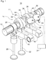
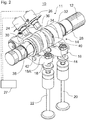
- variable valve train 10 In the Figures 1 and 2 a variable valve train 10 is shown.
- the variable valve train 10 has a camshaft 12 and a cam carrier 14.
- the variable valve train 10 has a first and second transmission device 16 and 18 as well as a first and second outlet valve 20 and 22.
- the variable valve drive 10 has a first actuator 24 and a second actuator 26.
- the cam carrier 14, the transmission devices 16 and 18 and the actuators 24 and 26 form a sliding cam system 11.
- the camshaft 12 is designed as an output camshaft which actuates output valves 20 and 22.
- the camshaft 12 is part of a double camshaft system (not shown in detail), which additionally has an intake camshaft (not shown) for actuating one or more intake valves.
- the camshaft 12 is arranged together with the inlet camshaft as an overhead camshaft.
- the camshaft 12 and the intake camshaft thus form a so-called DOHC system (double overhead camshaft).
- the camshaft 12 could also form a so-called SOHC system (single overhead camshaft).
- the camshaft 12 can also be arranged as an underlying camshaft.
- the cam carrier 14 is arranged in a rotationally fixed manner on the camshaft 12.
- the cam carrier 14 is also arranged to be axially displaceable along a longitudinal axis of the camshaft 12. Of the Cam carrier 14 can be axially displaceable between a first stop 28 and a second stop 30.
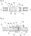
- the cam carrier 14 has three cams 32, 34 and 36 which are offset from one another in a longitudinal direction of the cam carrier 14 and the camshaft 12.
- the first cam 32 is arranged at a first end of the cam carrier 14 and is designed for normal operation, as described later in detail by way of example.
- the second cam 34 is arranged adjacent to the first cam 32 and is designed for an engine braking operation, as will also be described later in detail by way of example.
- the engine braking mode can be used to slow down and / or brake the motor vehicle when driving downhill.
- the engine braking operation can also be used to reduce an engine speed of the motor vehicle for upshifting assistance when changing gear into a higher gear.
- the third cam 36 is arranged at a distance from the second cam 34 and the second end of the cam carrier 14.
- the third cam 36 is designed for normal operation.
- the third cam 36 is shaped like the first cam 32.
- the cam carrier 14 also has a first cam-free section 38 and a second cam-free section 40.
- the first cam-free section 38 is arranged at the second end of the cam carrier 14.
- the second cam-free section 40 is arranged between the second cam 34 and the third cam 36.
- a first engagement track (switching gate) 42 extends spirally around a longitudinal axis of the cam carrier 14.
- a second engagement track (switching gate) 44 extends spirally around the longitudinal axis of the cam carrier 14.
- the actuators 24 and 26 selectively engage in the engagement tracks 42, 44 with extendable elements (not shown in detail).
- the first actuator 24 can selectively engage in the first engagement track 42 for moving the cam carrier 14 from one axial position to another axial position. In a first axial position, the cam carrier 14 rests against the second stop 30. In a second axial position, the cam carrier 14 rests against the first stop 28. In the Figures 1 to 4 the cam carrier is shown in the first axial position.
- the second actuator 26 in turn can selectively engage in the second engagement track 44. Then the cam carrier 14 is shifted from the first axial position to the second axial position.
- the first actuator 24 and the second actuator 26 are controlled by a schematically illustrated control unit 27 ( Figures 1 and 2 ) controlled.
- the displacement is triggered by the fact that the extended element of the respective actuator 24, 26 is stationary with respect to an axial direction of the camshaft 12.
- the displaceable cam carrier 14 is displaced in a longitudinal direction of the camshaft 12 due to the spiral shape of the engagement tracks 42, 44 when the extended element engages in the respective engagement tracks 42, 44.
- the displaceable element of the respective actuator 24, 26 is guided by the respective engagement track 42, 44 opposite to the extension direction and is thus retracted.
- the displaceable element of the respective actuator 24, 26 disengages from the respective engagement track 42, 44.
- the first transmission device 16 and the second transmission device 18 establish an operative connection between the cam carrier 14 and the outlet valves 20, 22.
- the first exhaust valve 20 is operated (opened) when the first cam 32 or the second cam 34 pushes the first transmission device 16 downward.
- the second exhaust valve 22 is actuated (opened) when the third cam 36 pushes the second transmission device 18 downwards.
- the first transmission device 16 is in operative connection between the first cam 32 and the first exhaust valve 20. In other words, the first transmission device 16 is not in operative connection between the second cam 34 and the first exhaust valve in the first axial position of the cam carrier 14 20.
- the first outlet valve 20 is actuated according to a contour of the first cam 32.
- the first transmission device 16 is in operative connection between the second cam 34 and the first outlet valve 20.
- the first outlet valve 20 is actuated according to a contour of the second cam 34.
- the second transmission device 18 In the first axial position of the cam carrier 14, the second transmission device 18 is in operative connection between the third cam 36 and the second outlet valve 22.
- the second outlet valve 22 is actuated according to a contour of the third cam 36.
- the second transmission device 18 In the second axial position of the cam carrier 14, the second transmission device 18 does not actuate the second outlet valve 22.
- a contact area 18A of the second transmission device 18 lies at the same axial position with respect to the camshaft 12 as the first cam-free section 38.
- the first cam-free section 38 has no elevation for actuating the second transmission device 18. If the cam carrier 14 is in the second axial position, the second outlet valve 22 is not actuated.
- the first cam-free section 38 thus has two functions. On the one hand, the first cam-free section 38 receives the first guide track 42. On the other hand, the first cam-free section 38 serves to ensure that the second outlet valve 42 is not actuated in the second axial position of the cam carrier 14. This functional integration is favorable for reasons of installation space.
- the first transmission device 16 and the second transmission device 18 are each designed as a rocker arm. In other embodiments, the transmission devices 16 and 18 can be designed as rocker arms or tappets. In some embodiments, the transfer devices 16 and 18 may include cam followers, for example in the form of rotatable rollers.
- the locking device 46 has an elastic element 48 and a locking body 50.
- the elastic element 48 is arranged in a blind hole in the camshaft 12.
- the elastic element 48 biases the locking body 50 against the cam carrier 14.
- First and second recesses 52 and 54 are arranged in an inner circumferential surface of the cam carrier 14. To lock the cam carrier 14, the locking body 50 is pressed into the first recess 52 when the cam carrier 14 is in the first axial position. In the second axial position of the cam carrier 14, the locking body 50 is pressed into the second recess 54.
- Figure 5 shows a complete four-stroke cycle consisting of compression, expansion, expulsion and intake.
- Curve A describes the profile of the cylinder pressure in the engine braking mode when the second cam 34 is in operative connection with the first exhaust valve 20.
- Curve B shows the course of the valve lift of the first exhaust valve 20 when the first cam 32 is in connection with the first exhaust valve 20 (ie during normal operation).
- the third curve C shows the course of the valve lift of an intake valve both during normal operation and in engine braking operation.
- Curve D shows the course of the valve lift of the first exhaust valve 20 when the second cam 34 is in operative connection with the first exhaust valve 20 (ie during engine braking operation).
- Curve B shows that the exhaust valve is open in normal operation during the exhaust stroke.
- Curve C shows that the intake valve is open in normal operation and in braking operation during the intake stroke (intake stroke).
- Curve D shows that the exhaust valve is opened slightly at the end of the compression stroke in the area of top dead center at around 60 ° CA to 100 ° CA before top dead center.
- the exhaust valve is opened further at top dead center and closes at approximately bottom dead center at the end of the expansion stroke. Opening the exhaust valve at the end of the compression stroke has the effect that the compressed air in the cylinder is pushed through the opened exhaust valve into the exhaust system by the piston moving to top dead center.
- the previously performed compression work brakes the crankshaft and thus the combustion engine.
- the cylinder pressure initially rises in the compression stroke, but then falls as a result of the opening of the exhaust valve before top dead center (cf. curve A).
- the open exhaust valve during the expansion stroke causes air to be drawn from the exhaust pipes back into the cylinder. At the end of the expansion stroke, the cylinder is essentially filled with air from the exhaust system.
- Curve D also shows that the outlet valve initially remains closed after reaching bottom dead center at the end of the expansion stroke.
- the exhaust valve opens in the area of top dead center. The opening takes place again at around 60 ° CA to 100 ° CA before top dead center.
- the closed outlet valve during the first section of the exhaust stroke has the effect that the air sucked in during the expansion stroke is compressed while doing work.
- the cylinder pressure increases (curve A).
- the compression work brakes the crankshaft and thus the combustion engine.
- the opening of the exhaust valve at the end of the exhaust stroke results in the air being pushed through the opened exhaust valve into the exhaust system.
- the cylinder is filled with air again through the open intake valve or valves (curve C). The cycle starts again.
- the use of the second cam to control the exhaust valve results in a double compression with subsequent decompression, so that engine braking functionality is ensured.
- the Figure 6A shows a cross section through the second cam 34.
- the Figure 6B shows a cross section through the first cam 32.
- the second cam 34 is off to achieve curve D.
- Figure 5 educated.
- the second cam 34 has in particular a first elevation 34A, a second elevation 34B and a third elevation 34C.
- the first, second and third elevations 34A-34C are arranged offset in the circumferential direction around the second cam 34.
- the first elevation 34A leads to the opening of an exhaust valve at the end of the compression stroke.
- the second elevation 34B which extends from the first elevation 34A, leads to an enlarged opening of an exhaust valve during the expansion stroke.
- the third elevation 34C leads to an opening of an exhaust valve at the end of the exhaust stroke.
- the first protrusion 34A has the smallest height of the protrusions 34A-34C measured in a radial direction of the camshaft 12.
- the second protrusion 34B has the greatest height of the protrusions 34A-34C measured in a radial direction of the camshaft 12.
- the third protrusion 34C is smaller than that second elevation 34B and larger than the first elevation 34A. Different heights of the elevations 34A-34C lead to correspondingly different valve lifts (cf. Figure 5 ).
- the first, second and third elevations 34A-34C are each arranged circumferentially offset from an elevation 32A of the first cam 32.
- the first cam 32 is off to achieve curve B.
- Figure 5 educated.
- the elevation 32A of the first cam 32 leads to an opening of an exhaust valve during the exhaust stroke.
- the elevation 32A is higher than the elevations 34A-34C when measured in a radial direction of the camshaft 12.
- the valve lift through elevation 32A is greater than through elevations 34A-34C.
- the Figure 6B also shows the locking device 46 with the elastic element 48, the locking body 50 and the first recess 52.
- the Figure 7 shows an exemplary method for upshifting assistance.
- the method begins in step S100 with the initiation of an upshift.
- an automatic transmission it can be determined, for example on the basis of an engine speed and / or a throttle valve position, that a higher gear must be shifted with a higher ratio.
- the transmission can for example be an automatic double clutch transmission of a commercial vehicle, for example a truck or a bus.
- the higher gear ratio of the higher gear leads to a reduced transmission speed. Therefore, an engine speed must be decreased for shifting to the higher gear. The faster the engine speed can be reduced, the shorter the time the shift can be completed.
- the switching cam system 11 switches over from the first cam 32 to the second cam 34 in step S102.
- the first exhaust valve 20 is consequently actuated with the second cam 34 (step S104).
- the double decompression caused by the second cam 34 results in a rapid decrease in engine speed.
- the second cam 34 is used to actuate the first exhaust valve 20 until the actual engine speed equals a setpoint engine speed.
- the setpoint engine speed can essentially correspond to a transmission speed with the higher gear engaged.
- step S106 it is checked whether a predetermined switchover condition is met. It can expediently be checked whether the actual engine speed is the same as the target engine speed. If the actual engine speed is not the same as the setpoint engine speed, the first exhaust valve 20 is further actuated with the second cam 34, so that the engine speed can be further reduced. If the actual engine speed corresponds to the setpoint engine speed, a switch is made to the first cam 32 in step S108. Thus, the first exhaust valve 20 is subsequently operated by the first cam 32 (step S110).
- the transmission can subsequently be operated with the higher gear (step S112) and the upshifting process can be completed.
- the Figure 8 shows engine speed curves, turbocharger speed curves and boost pressure curves that can be achieved with the method.
- the Figure 8 five different engine speed profiles 1A-5A, five different turbine speed profiles 1B-5B and five different boost pressure profiles 1C-5C.
- the turbine speed curves 1B-5B relate to the speed of a turbine of an exhaust gas turbocharger of the internal combustion engine.
- the boost pressure curves relate to a boost pressure provided by the compressor of the exhaust gas turbocharger.
- the five curves in each case for the engine speed, the turbine speed and the boost pressure relate, among other things, to different embodiments of the method disclosed herein for upshift assistance.
- the dashed curves 2A, 2B and 2C relate to curves that can be achieved when two cylinders are used for upshifting assistance in a six-cylinder internal combustion engine. In other words, only two of the six cylinders are actuated with the corresponding second cam 34 during the upshift process. That is, only two of the six cylinders are operated in an engine braking mode during the upshift.
- the dotted curves 3A, 3B, 3C, the semicolon curves 4A, 4B, 4C and the double-dot chain curves 5A, 5B, 5C relate to embodiments in which three, four or all cylinders are in one during the upshift process by the slide cam system 11 Motor braking operation are operated.
- the solid curves 1A, 1B, 1C show a profile in which no cylinder is operated in an engine braking mode during the upshift process.
- a turbocharger speed and a boost pressure of the turbocharger can also be positively influenced during the upshift.
- a turbocharger speed (curve 1B) and a boost pressure (curve 1C) gradually decrease during the upshift.
- the low boost pressure can be perceived as a turbo lag after shifting into higher gear.
- the turbocharger speed and the boost pressure can be positively influenced during the upshift, so that preferably no, but at least only a reduced, turbo lag is perceptible after engaging the higher gear.
- the turbocharger speed and the boost pressure can be positively influenced during the upshift, so that preferably no, but at least only a reduced, turbo lag is perceptible after engaging the higher gear.
- no exhaust gas throttle valve is used for engine braking operation, which also reduces a speed of the turbine of the turbocharger when throttling the exhaust gas mass flow.
- boost pressure p L can be maintained or even increased, as the comparison of curves 2C-5C shows.
- a higher boost pressure p L can be achieved in a shorter time at a threshold speed, for example U M1 , as with the aid of the vertical dotted lines in FIG Figure 8 can be seen.
- first exhaust valve 20 For example, it is possible to make actuation of the first exhaust valve 20 with the second cam 34 dependent on various parameters. On the one hand, it can thus be determined whether the first exhaust valve 20 is actuated at all with the second cam 34 and, if so, how many cylinders are used in the engine braking mode. A balance can thus be found between wear of the variable valve drive 10 and a rapid upshift. Such parameters can in particular be a reduction in speed and an increase in torque which are required during the upshift. In addition, for example, there is a desired duration of the upshift, one desired turbocharger speed and / or a desired boost pressure as parameters into consideration.
- threshold values can be stored for certain operating conditions of the internal combustion engine, on the basis of which it is determined whether and how many cylinders are operated in engine braking mode during upshifting.
- the threshold values can relate to required speed reductions, required torque increases, desired upshift times, desired turbocharger speeds and / or desired boost pressures.
- a first group of sliding cam systems 11 actuates the corresponding first exhaust valve 20 with the corresponding second cam 34 during the upshifting process.
- the method disclosed herein can preferably be used for upshifting assistance in an internal combustion engine of a commercial vehicle and generally in large engines, since a time period for upshifting can be comparatively long here.
- the method for upshifting assistance of the internal combustion engine can use the sliding cam system 11.
- the control unit 27 can control the actuators 24 and 26 according to the method disclosed herein for upshifting support of the internal combustion engine.
- the procedure can also be a Use another variable valve train to provide the engine brake.
- another system is used for the corresponding actuation of the exhaust valves, in which a first exhaust valve of the internal combustion engine is initially kept closed in the compression cycle and / or in the exhaust cycle for compressing air and before reaching top dead center a piston movement is used to decompress the compressed air Air is opened.
Landscapes
- Engineering & Computer Science (AREA)
- General Engineering & Computer Science (AREA)
- Mechanical Engineering (AREA)
- Chemical & Material Sciences (AREA)
- Combustion & Propulsion (AREA)
- Output Control And Ontrol Of Special Type Engine (AREA)
- Valve Device For Special Equipments (AREA)
Description
- Die Erfindung betrifft ein Verfahren zur Hochschaltunterstützung und einen variablen Ventiltrieb.
- Im Nutzfahrzeugbereich wird die Motordrehzahlabsenkung für die Angleichung der Drehzahlen von Motor und Getriebe beim Hochschalten eines Ganges typischerweise mittels vorhandener Motorbremsklappen ermöglicht. Je nach Lage der Klappe (vor oder nach einem Abgasturbolader) kann das Absenken der Motordrehzahl relativ lange dauern, da das Abgas stromaufwärts der Klappe bis zum Brennraum aufgestaut werden muss. Der Kolben muss das Abgas im Zylinder gegen das aufgestaute Abgas im Abgastrakt ausschieben. Es kommt zu einer Mehrarbeit. Dadurch kommt es zu einer Verringerung der Motordrehzahl.
- Neben der zeitlichen Länge der Motordrehzahlabsenkung mittels Motorbremsklappe weist das bekannte Verfahren ferner den Nachteil auf, dass es zu einem Turboloch am Ende des Hochschaltvorgangs kommen kann. Dies liegt daran, dass die Abgasturbine des Abgasturboladers aufgrund des aufgestauten Abgases nicht voll durchströmt wird und somit der Ladedruck im Motorbremsbetrieb erheblich abnimmt.
- Die
US 5 947 863 A ist auf ein Verfahren zum Steuern des Eingangsdrehmoments eines Getriebes während eines Übersetzungsschaltvorgangs gerichtet. Das Eingangsdrehmoment wird durch vorgegebene Maßnahmen, z. B. mittels eines variablen Ventiltriebs, über den zu Beginn des Schaltvorgangs vorhandenen Wert hinaus in Abhängigkeit von der vorliegenden Schaltart erhöht oder verringert. - Die
US 2015/066318 A1 offenbart ein Steuerverfahren für ein Fahrzeuggetriebe. Eine Motorbremswirkung wird aktiviert. Wenn die Drehzahl nach der Motorbremsung auf einen vorbestimmten Wert oder weniger reduziert wird, wird ein Schaltvorgang durchgeführt. - Die
EP 0 638 455 A1 offenbart ein Steuerverfahren zum Steuern des Hochschaltens in einem automatisierten mechanischen Getriebesystem, das mit einer Motor-Kompressionsbremse versehen ist. Die Motor-Kompressionsbremse wird während eines Hochschaltens des Getriebes betrieben. - Die
US 2006/199699 A1 offenbart ein Verfahren, bei dem während der Fahrt des Fahrzeugs mit Hilfe eingegebener Informationen über mindestens die Steigung der Fahrbahn und die Drosselklappenstellung ein zukünftiger Widerstand gegen Vorwärtsbewegung und den Zeitraum bis zu einer zukünftigen Transiente im Betriebszustand des Motors berechnet wird, zum Beispiel in Verbindung mit einem zukünftigen Gangwechsel in einem mit dem Motor verbundenen Getriebe. - Die
US 2004/260443 A1 bezieht sich auf ein Verfahren zum Hochschalten eines automatischen oder halbautomatischen Getriebes, das mit einem Motor verbunden ist, der mit einer zusätzlichen Motorbremse ausgestattet ist, wobei das Verfahren das Bestimmen eines erwarteten Wertes der Geschwindigkeitsableitung des Motors während des Schaltens umfasst. - Der Erfindung liegt die Aufgabe zu Grunde, ein verbessertes Verfahren zur Hochschaltunterstützung und eine Vorrichtung hierzu vorzusehen, die insbesondere eine Verkürzung des Hochschaltvorgangs und einen höheren Ladedruck am Ende des Hochschaltvorgangs ermöglichen.
- Die Aufgabe wird gelöst durch ein Verfahren zur Hochschaltunterstützung und einen variablen Ventiltrieb gemäß den unabhängigen Ansprüchen. Vorteilhafte Weiterbildungen sind in den abhängigen Ansprüchen und der Beschreibung angegeben.
- Das Verfahren zur Hochschaltunterstützung bei einem Gangwechsel eines mit einem Verbrennungsmotor verbundenen Getriebes weist das Initiieren eines Hochschaltvorgangs und das Verringern einer Motordrehzahl des Verbrennungsmotors durch Schalten in einen Motorbremsbetrieb auf. Im Motorbremsbetrieb wird ein erstes Auslassventil des Verbrennungsmotors im Verdichtungstakt und/oder im Ausschubtakt zur Kompression von Luft zunächst geschlossen gehalten und vor Erreichen eines oberen Totpunkts einer Kolbenbewegung zur Dekompression der verdichteten Luft geöffnet. Alternativ oder zusätzlich wird mittels eines variablen Ventiltriebs, insbesondere eines Schiebenockensystems, des Verbrennungsmotors in den Motorbremsbetrieb geschaltet.
- Durch die Dekompression am Ende des Verdichtungstaktes und/oder am Ende des Ausschubtaktes kann sehr schnell eine Motorbremswirkung erzielt werden, da nicht erst Abgas stromaufwärts eines Abgasdrosselventils aufgestaut werden muss. Dadurch kann die Drehzahl in kurzer Zeit abgesenkt werden und somit ein schneller Hochschaltvorgang realisiert werden. Zusätzlich oder alternativ wird der Motorbremsbetrieb durch Veränderung der Ventilsteuerkurven durch den variablen Ventiltrieb dargestellt. Dies ermöglicht einen Motorbremsbetrieb bei dem keine Abgasdrosselklappe verstellt werden muss, sodass eine Turbinendrehzahl einer Abgasturbine weniger stark abgesenkt wird. Damit kann ein Turboloch nach dem Hochschaltvorgang verkleinert oder verhindert werden.
- Insbesondere kann im Motorbremsbetrieb vom jeweiligen Zylinder des Verbrennungsmotors negative Arbeit verrichtet werden.
- Während des Motorbremsbetriebes kann insbesondere kein Kraftstoff zu den im Motorbremsbetrieb betriebenen Zylindern geleitet werden und keine Zündung stattfinden.
- Das Verfahren kann insbesondere zur Hochschaltunterstützung bei einem Gangwechsel eines, insbesondere vollautomatischen, Getriebes, das mit einem Verbrennungsmotor verbunden ist, verwendet werden.
- Es versteht sich, dass auch mehrere (erste) Auslassventile verschiedener Zylinder des Verbrennungsmotors in den Motorbremsbetrieb geschaltet werden können.
- In einer weiteren Variante weist das Schiebenockensystem einen auf einer Nockenwelle des Verbrennungsmotors drehfest und axial verschiebbar angeordneten Nockenträger mit dem ersten Nocken und dem in einer Längsrichtung der Nockenwelle versetzt angeordneten zweiten Nocken auf.
- In einer besonders bevorzugten Ausführungsvariante weist das Verfahren zusätzlich das Halten und/oder Erhöhen eines Ladedrucks und/oder einer Turboladerdrehzahl eines Turboladers des Verbrennungsmotors auf. Dies wird ermöglicht durch Ausschieben der verdichteten Luft zu einer Abgasturbine des Turboladers im Verdichtungstakt und/oder im Ausschubtakt durch Öffnen des ersten Auslassventils vor Erreichen des oberen Totpunkts der Kolbenbewegung. Dies hat den Vorteil, dass ein Turboloch nach dem Hochschalten verhindert oder zumindest verkleinert werden kann.
- In einem Ausführungsbeispiel weist das Verfahren das Erfassen einer erforderlichen Drehzahlabsenkung für den Hochschaltvorgang, einer erforderlichen Drehmomenterhöhung für den Hochschaltvorgang, einer gewünschten Dauer des Hochschaltvorgangs, einer gewünschten Turboladerdrehzahl insbesondere am Ende des Hochschaltvorgangs und/oder einem gewünschten Ladedruck insbesondere am Ende des Hochschaltvorgangs auf. Der Schritt des Verringerns der Motordrehzahl des Verbrennungsmotors durch Schalten in den Motorbremsbetrieb wird insbesondere in Abhängigkeit der erforderlichen Drehzahlabsenkung, der erforderlichen Drehmomenterhöhung, der gewünschten Dauer des Hochschaltvorgangs, der gewünschten Turboladerdrehzahl und/oder des gewünschten Ladedrucks durchgeführt. Folglich kann eine Benutzung und somit bspw. ein Verschleiß des Umschaltsystems verhindert werden, wenn beispielsweise nur geringe Drehzahlabsenkungen erforderlich sind.
- Vorzugsweise kann eine erste Gruppe von Zylindern während des Hochschaltvorgangs in den Motorbremsbetrieb geschaltet werden. Eine zweite Gruppe von Zylindern des Verbrennungsmotors kann während des Hochschaltvorgangs im Normalbetrieb weiterbetrieben werden.
- Insbesondere kann eine Anzahl von Zylindern in der ersten Gruppe und/oder der zweiten Gruppe in Abhängigkeit von der erforderlichen Drehzahlabsenkung, der erforderlichen Drehmomenterhöhung, der gewünschten Dauer des Hochschaltvorgangs, der gewünschten Turboladerdrehzahl und/oder dem gewünschten Ladedruck bestimmt werden. Damit können je nach Anforderung (z.B. erforderlicher Lastsprung) mehr oder weniger Zylinder während des Hochschaltvorgangs im Motorbremsbetrieb betrieben werden.
- In einer bevorzugten Variante erfolgt eine Zuordnung zur ersten Gruppe und/oder zur zweiten Gruppe rollierend, insbesondere rollierend zwischen aufeinanderfolgenden Hochschaltvorgängen. Somit kann ein Verschleiß des Umschaltsystems vergleichmäßigt werden.
- In einer weiteren Ausführungsvariante ist der zweite Nocken so ausgebildet ist, dass das erste Auslassventil zwischen 100° KW und 60° KW (Kurbelwinkel) vor dem Erreichen des oberen Totpunkts öffnet, nach dem Öffnen im Ausschubtakt im Bereich zwischen dem oberen Totpunkt und 30° KW nach dem oberen Totpunkt schließt und/oder nach dem Öffnen im Verdichtungstakt im Bereich zwischen dem unteren Totpunkt und 30° KW nach dem unteren Totpunkt schließt. Damit kann eine erhebliche Motorbremswirkung aufgrund der zweifachen Dekompression erzielt werden.
- In einer weiteren Ausführungsform weist das Verfahren das Geschlossen-Halten eines zweiten Auslassventils des Verbrennungsmotors während des Hochschaltvorgangs auf. Das zweite Auslassventil ist insbesondere demselben Zylinder des Verbrennungsmotors zugeordnet wie das erste Auslassventil. Durch das Geschlossen-Halten des zweiten Auslassventils kann eine Belastung des Umschaltsystems während des Motorbremsbetriebs verringert werden, da nicht auch das zweite Auslassventil gegen den Druck im Zylinder geöffnet werden muss.
- Das zweite Auslassventil kann insbesondere mittels eines nockenfreien Abschnitts des Schiebenockensystems während des Hochschaltvorgangs geschlossen gehalten werden.
- In einer Weiterbildung weist das Schiebenockensystem einen ersten Nocken für einen Normalbetrieb des Verbrennungsmotors und einen zweiten Nocken für den Motorbremsbetrieb des Verbrennungsmotors auf. Das Schiebenockensystem setzt wahlweise den ersten Nocken und das erste Auslassventil in Wirkverbindung oder den zweiten Nocken und das erste Auslassventil in Wirkverbindung. Das Schiebenockensystem stellt ein zuverlässiges und besonders schnelles System zum Umschalten in den Motorbremsbetrieb bereit.
- In einer vorteilhaften Weiterbildung weist das Schalten in den Motorbremsbetrieb das Umschalten von dem ersten Nocken auf den zweiten Nocken durch das Schiebenockensystem und das Betätigen des ersten Auslassventils mittels des zweiten Nockens auf. Der zweite Nocken hält das erste Auslassventil im Verdichtungstakt und/oder im Ausschubtakt zunächst geschlossen und öffnet es vor Erreichen des oberen Totpunkts der Kolbenbewegung.
- In einer Variante wird das zweite Auslassventil mittels eines nockenfreien Abschnitts des Schiebenockensystems während des Hochschaltvorgangs geschlossen gehalten.
- In einer Ausführungsvariante weist das Verfahren das Umschalten von dem zweiten Nocken auf den ersten Nocken durch das Schiebenockensystem auf, wenn die Motordrehzahl auf eine gewünschte Drehzahl, insbesondere eine Getriebedrehzahl des mit dem Verbrennungsmotor verbundenen Getriebes, verringert wurde. Damit kann der Hochschaltvorgang beendet und der Verbrennungsmotor wieder vollständig im Normalbetrieb betrieben werden.
- In einer Ausführungsform weist der variable Ventiltrieb eine erste Gruppe von Schiebenockensystemen und eine zweite Gruppe von Schiebenockensystemen auf. Die erste Gruppe betätigt während des Hochschaltvorgangs das entsprechende erste Auslassventil mittels des entsprechenden zweiten Nockens. Die zweite Gruppe betätigt während des Hochschaltvorgangs das entsprechende erste Auslassventil mittels des entsprechenden ersten Nockens, der das erste Auslassventil im Ausschubtakt öffnet.
- Insbesondere kann eine Anzahl von Schiebenockensystemen in der ersten Gruppe und/oder der zweiten Gruppe in Anhängigkeit von einer erforderlichen Drehzahlabsenkung zum Hochschalten, einer erforderlichen Drehmomenterhöhung zum Hochschalten, einer gewünschten Zeitdauer des Hochschaltvorgangs, einer gewünschten Turboladerdrehzahl insbesondere am Ende des Hochschaltvorgangs und/oder einem gewünschten Ladedruck insbesondere am Ende des Hochschaltvorgangs bestimmt werden. Ist bspw. eine besonders kurze Hochschaltdauer gewünscht, so können mehrere oder alle Schiebenockensystem auf den jeweiligen zweiten Nocken zum Betätigen des jeweiligen ersten Auslassventils umgeschaltet werden.
- In einer vorteilhaften Weiterbildung erhöht sich die Anzahl von Schiebenockensystemen in der ersten Gruppe mit einer Vergrößerung der erforderlichen Drehzahlabsenkung, einer Vergrößerung der erforderlichen Drehmomenterhöhung, einer Verkürzung der gewünschten Zeitdauer des Hochschaltvorgangs, einer Vergrößerung der gewünschten Turboladerdrehzahl und/oder einer Vergrößerung des gewünschten Ladedrucks.
- In einer bevorzugten Variante erfolgt eine Zuordnung der Schiebenockensysteme zur ersten Gruppe und zweiten Gruppe rollierend, insbesondere rollierend zwischen aufeinanderfolgenden Hochschaltvorgängen. Somit kann ein Verschleiß der Schiebenockensysteme vergleichmäßigt werden.
- In einem weiteren Ausführungsbeispiel wird der Hochschaltvorgang automatisch in Anhängigkeit von einer Motordrehzahl und/oder einer Drosselklappenstellung initiiert. Hierbei kann insbesondere ein automatisches Getriebe verwendet werden.
- In einer Ausführungsform wird im Getriebe während des Hochschaltvorgangs von einem Getriebegang zu einem anderen Getriebegang mit höherer Übersetzung geschaltet.
- Die Erfindung betrifft auch einen variabler Ventiltrieb für einen Verbrennungsmotor eines Kraftfahrzeugs, insbesondere Nutzfahrzeugs. Der variable Ventiltrieb weist ein erstes Auslassventil, eine Nockenwelle und ein Schiebenockensystem auf. Das Schiebenockensystem weist einen Nockenträger, der auf der Nockenwelle drehfest und axial verschiebbar angeordnet ist und einen ersten Nocken und einen zweiten Nocken aufweist, auf. Der erste Nocken und der zweite Nocken sind in einer Längsrichtung der Nockenwelle versetzt angeordnet. Der variable Ventiltrieb weist eine Steuereinheit auf, die dazu ausgebildet ist, das Verfahren zur Hochschaltunterstützung wie hierin offenbart durchzuführen.
- Der Begriff "Steuereinheit" bezieht sich auf eine Steuerelektronik, die je nach Ausbildung Steuerungsaufgaben und/oder Regelungsaufgaben übernehmen kann.
- Vorzugsweise ist der Nockenträger axial verschiebbar zwischen einer ersten Axialposition und einer zweiten Axialposition auf der Nockenwelle angeordnet. Der Ventiltrieb weist ferner eine Übertragungsvorrichtung auf. In der ersten Axialposition des Nockenträgers ist die Übertragungsvorrichtung in Wirkverbindung zwischen dem ersten Nocken und dem ersten Auslassventil. In der zweiten Axialposition des Nockenträgers ist die Übertragungsvorrichtung in Wirkverbindung zwischen dem zweiten Nocken und dem ersten Auslassventil. Der erste Nocken ist für einen Normalbetrieb des Verbrennungsmotors ausgebildet, bei dem der erste Nocken das erste Auslassventil im Ausschubtakt offen hält. Der zweite Nocken ist für einen Motorbremsbetrieb des Verbrennungsmotors ausgebildet, bei dem der zweite Nocken das erste Auslassventil im Verdichtungstakt und/oder im Ausschubtakt zunächst geschlossen hält und vor Erreichen eines oberen Totpunkts einer Kolbenbewegung eines Kolbens des Verbrennungsmotors das erste Auslassventil öffnet.
- Es versteht sich, dass während der zweite Nocken im Eingriff mit der ersten Übertragungsvorrichtung ist, das oder die Einlassventile weiterhin nur während des Einlasstaktes öffnen. Es kommt jedoch zu keiner Kraftstoffeinleitung und Gemischzündung.
- Der erste Nocken und der zweite Nocken können eine unterschiedliche Nockenkontur aufweisen und/oder in einer Umfangsrichtung des Nockenträgers versetzt zueinander angeordnet sein.
- In einem Ausführungsbeispiel weist der Nockenträger einen dritten Nocken, der wie der erste Nocken ausgebildet ist, und einen nockenfreien Abschnitt auf. Der erste Nocken, der zweite Nocken, der dritte Nocken und der nockenfreie Abschnitt sind in einer Längsrichtung der Nockenwelle versetzt angeordnet. Insbesondere grenzen der erste Nocken an den zweiten Nocken und der dritte Nocken an den nockenfreien Abschnitt. Die Integration eines dritten Nockens und des nockenfreien Abschnitts ermöglicht, dass ein zweites Auslassventil im Bremsbetrieb anders betätigt werden kann als das erste Auslassventil. Im Normalbetrieb kann das zweite Auslassventil hingegen wie das erste Auslassventil betätigt werden, da der dritte Nocken und der erste Nocken gleich geformt sind.
- Der nockenfreie Abschnitt wird auch als Nullnocken bezeichnet. Der nockenfreie Abschnitt weist eine Zylindermantelfläche ohne Erhebung zum Betätigen der Übertragungsvorrichtung auf.
- Vorzugsweise weist der Ventiltrieb ein zweites Auslassventil, das insbesondere demselben Zylinder zugeordnet ist wie das erste Auslassventil, und eine zweite Übertragungsvorrichtung auf. Die zweite Übertragungsvorrichtung ist in der ersten Axialposition des Nockenträgers in Wirkverbindung zwischen dem dritten Nocken und dem zweiten Auslassventil. In der zweiten Axialposition des Nockenträgers hält die zweite Übertragungsvorrichtung das zweite Auslassventil aufgrund der Ausbildung des nockenfreien Abschnitts geschlossen. Hierbei kann der nockenfreie Abschnitt in Eingriff oder außer Eingriff mit der zweiten Übertragungsvorrichtung sein.
- Es versteht sich, dass die zweite Übertragungsvorrichtung in der zweiten Axialposition des Nockenträgers mit keinem anderen Nocken des Nockenträgers in Wirkverbindung ist.
- Diese Ausgestaltung hat den Vorteil, dass nur das erste Auslassventil für den Bremsbetrieb verwendet wird. Das zweite Auslassventil verbleibt dann, wenn das erste Auslassventil für den Bremsbetrieb verwendet wird, während des gesamten Zyklus geschlossen. Damit können die Belastungen auf den variablen Ventiltrieb verringert werden. Insbesondere ergeben sich beim Öffnen eines Auslassventils gegen den Druck im Zylinder große Flächenpressungen zwischen dem Nocken und der Kontaktfläche der Übertragungsvorrichtung. In Ausgestaltungen, bei denen beide Auslassventile während des Bremsbetriebs betätigt werden, muss der variable Ventiltrieb entsprechend robuster gestaltet werden.
- In einem alternativen Ausführungsbeispiel weist der Ventiltrieb ferner ein zweites Auslassventil auf, das insbesondere demselben Zylinder zugeordnet ist wie das erste Auslassventil. Die erste Übertragungsvorrichtung ist in der ersten Axialposition des Nockenträgers zusätzlich in Wirkverbindung zwischen dem ersten Nocken und dem zweiten Auslassventil und in der zweiten Axialposition zusätzlich in Wirkverbindung zwischen dem zweiten Nocken und dem zweiten Auslassventil.
- Der erste Nocken und der dritte Nocken können eine gleiche Nockenkontur aufweisen und/oder in einer Umfangsrichtung des Nockenträgers zueinander (fluchtend) ausgerichtet angeordnet sein.
- Diese Ausgestaltung hat den Vorteil, dass beide Auslassventile für den Bremsbetrieb verwendet werden. Beide Auslassventile werden über die gleiche Übertragungsvorrichtung und den gleichen Nocken betätigt.
- In einer Ausführungsvariante weist der Nockenträger eine erste Eingriffsspur zum axialen Verschieben des Nockenträgers in eine erste Richtung auf. Die erste Eingriffsspur erstreckt sich insbesondere spiralförmig.
- Die erste Eingriffsspur ist dazu ausgebildet, im Eingriff mit einem Aktor den Nockenträger axial zu verschieben, zum Beispiel von der ersten Axialposition zu der zweiten Axialposition oder von der zweiten Axialposition zu der ersten Axialposition.
- In einem besonders bevorzugten Ausführungsbeispiel ist die erste Eingriffsspur in dem nockenfreien Abschnitt angeordnet. Mit anderen Worten gesagt, erstreckt sich die erste Eingriffsspur in dem Nullnocken.
- Eine solche Ausgestaltung bietet den Vorteil, dass der nockenfreie Abschnitt zum einen für die Axialverschiebung verwendet wird. Zum anderen sorgt der nockenfreie Abschnitt dafür, dass das zweite Auslassventil im Motorbremsbetrieb nicht geöffnet wird. Durch die Funktionsintegration kann ein Bauraum für den Nockenträger verkleinert werden.
- In einer weiteren Ausführungsvariante ist die erste Eingriffsspur und/oder der nockenfreie Abschnitt zwischen dem ersten Nocken und dem dritten Nocken oder an einem Ende des Nockenträgers angeordnet. Die Anordnung der Nocken, des nockenfreien Abschnitts und der ersten Eingriffsspur kann flexibel den jeweiligen Anforderungen angepasst werden.
- In einer Ausführungsform weist der Nockenträger eine zweite Eingriffsspur zum axialen Verschieben des Nockenträgers in eine zweite Richtung, die der ersten Richtung entgegengesetzt ist, auf. Die zweite Eingriffsspur ist zwischen dem ersten Nocken und dem dritten Nocken oder an einem Ende des Nockenträgers angeordnet. Die zweite Eingriffsspur kann sich insbesondere spiralförmig erstrecken.
- Die zweite Eingriffsspur ist dazu ausgebildet, im Eingriff mit einem Aktor den Nockenträger axial zu verschieben, zum Beispiel von der ersten Axialposition zu der zweiten Axialposition oder von der zweiten Axialposition zu der ersten Axialposition. Die erste und zweite Eingriffsspur bieten eine zuverlässige Möglichkeit zum Verschieben des Nockenträgers.
- In einer weiteren Ausführungsform weist der variable Ventiltrieb einen ersten Aktor auf, der dazu ausgebildet ist, selektiv in Eingriff mit der ersten Eingriffsspur zum Verschieben des Nockenträgers in die erste Richtung zu gelangen. Alternativ oder zusätzlich weist der variable Ventiltrieb einen zweiten Aktor auf, der dazu ausgebildet ist, selektiv in Eingriff mit der zweiten Eingriffsspur zum Verschieben des Nockenträgers in die zweite Richtung zu gelangen.
- Vorteilhafterweise weist die Nockenwelle eine Arretierungsvorrichtung mit einem elastisch vorgespannten Element auf, das in der ersten Axialposition des Nockenträgers in eine erste Ausnehmung im Nockenträger eingreift und in der zweiten Axialposition des Nockenträgers in eine zweite Ausnehmung im Nockenträger eingreift.
- Die Arretierungsvorrichtung hat den Vorteil, dass der Nockenträger in der ersten und zweiten Axialposition festgesetzt werden kann. Der Nockenträger kann sich somit nicht unbeabsichtigt entlang einer Längsrichtung der Nockenwelle verschieben.
- In einem weiteren Ausführungsbeispiel ist die erste Übertragungseinrichtung und/oder die zweite Übertragungseinrichtung als ein Hebel, insbesondere ein Kipphebel oder ein Schlepphebel, oder ein Stößel ausgebildet. Ein Schlepphebel kann beispielsweise bei einer obenliegenden Nockenwelle verwendet werden. Ein Kipphebel kann beispielsweise bei einer untenliegenden Nockenwelle verwendet werden.
- In einer weiteren Ausführungsvariante ist die Nockenwelle als eine obenliegende Nockenwelle oder eine untenliegende Nockenwelle angeordnet. Alternativ oder zusätzlich ist die Nockenwelle Teil eines Doppelnockenwellensystems ist, das zusätzlich eine weitere Nockenwelle zur Betätigung mindestens eines Einlassventils aufweist.
- In einer weiteren Ausführungsform kann die Nockenwelle für das oder die Auslassventile und/oder die weitere Nockenwelle für das oder die Einlassventile einen Phasensteller aufweisen. Der Phasensteller ist dazu ausgebildet, einen Drehwinkel einer Nockenwelle relativ zu einem Drehwinkel einer Kurbelwelle zu verstellen. Somit kann der Phasensteller eine Verstellung der Steuerzeiten für die jeweiligen Ventile ermöglichen. Der Phasenversteller kann beispielsweise als hydraulischer Phasenversteller, insbesondere als eine Schwenkmotorphasenversteller, ausgebildet sein. Eine solche Ausführungsform hat den Vorteil, dass die Flexibilität des Systems durch die Kombination mit dem verschiebbaren Nockenträger weiter gesteigert wird.
- In einer weiteren Ausführungsvariante ist der zweite Nocken so ausgebildet, dass das erste Auslassventil nach dem Öffnen im Verdichtungstakt mit einem größeren Ventilhub geöffnet wird als nach dem Öffnen im Ausschiebetakt. Alternativ oder zusätzlich ist der zweite Nocken so ausgebildet, dass das erste Auslassventil mit einem kleineren Ventilhub als beim ersten Nocken geöffnet wird. Das Vorsehen von mehrstufigen Ventilhüben, die kleiner sind als die Ventilhübe während des normalen Betriebs, verringert die Belastung auf den Ventiltrieb. Insbesondere beim Öffnen eines Auslassventils gegen den Druck im Zylinder wird der Ventiltrieb stark belastet.
- In Ausführungsformen, in denen der zweite Nocken auch zum Betätigen des zweiten Auslassventils verwendet wird, gelten die Ausführungen hierin, die sich auf die Wirkung des zweiten Nockens auf das erste Auslassventil beziehen, gleichermaßen für das zweite Auslassventil. In Ausführungsformen, in denen der dritte Nocken zum Betätigen des zweiten Auslassventils verwendet wird, gelten die Ausführungen hierin, die sich auf die Wirkung des ersten Nockens auf das erste Auslassventil beziehen, gleichermaßen für den dritten Nocken und das zweite Auslassventil.
- Letztlich betrifft die Erfindung zudem ein Kraftfahrzeug, insbesondere Nutzfahrzeug, mit einem variablen Ventiltrieb wie hierin offenbart. Das Nutzfahrzeug kann zum Beispiel ein Lastkraftwagen oder ein Omnibus sein.
- Die zuvor beschriebenen bevorzugten Ausführungsformen und Merkmale der Erfindung sind beliebig miteinander kombinierbar. Weitere Einzelheiten und Vorteile der Erfindung werden im Folgenden unter Bezug auf die beigefügten Zeichnungen beschrieben. Es zeigen:
- Figur 1
- eine perspektivische Ansicht eines beispielhaften variablen Ventiltriebs;
- Figur 2
- eine weitere perspektivische Ansicht des beispielhaften variablen Ventiltriebs;
- Figur 3
- eine Draufsicht auf eine Nockenwelle des beispielhaften variablen Ventiltriebs;
- Figur 4
- eine Längsschnittansicht der Nockenwelle von
Figur 3 entlang der Linie A-A; - Figur 5
- ein beispielhaftes Ventilsteuerungsdiagramm des variablen Ventiltriebs;
- Figur 6A
- eine erste Querschnittansicht der Nockenwelle von
Figur 4 entlang der Linie B-B; - Figur 6B
- eine zweite Querschnittansicht der Nockenwelle von
Figur 4 entlang der Linie C-C; - Figur 7
- ein beispielhaftes Verfahren zur Hochschaltunterstützung bei Gangwechseln gemäß der vorliegenden Offenbarung; und
- Figur 8
- ein Diagramm, das verschiedene Motordrehzahlverläufe, Turboladerdrehzahlverläufe und Ladedruckverläufe in Abhängigkeit von der Zeit zeigt.
- Die in den Figuren gezeigten Ausführungsformen stimmen zumindest teilweise überein, so dass ähnliche oder identische Teile mit den gleichen Bezugszeichen versehen sind und zu deren Erläuterung auch auf die Beschreibung der anderen Ausführungsformen bzw. Figuren verwiesen wird, um Wiederholungen zu vermeiden.
- In den
Figuren 1 und2 ist ein variabler Ventiltrieb 10 gezeigt. Der variable Ventiltrieb 10 weist eine Nockenwelle 12 und einen Nockenträger 14 auf. Zusätzlich weist der variable Ventiltrieb 10 eine erste und zweite Übertragungsvorrichtung 16 und 18 sowie ein erstes und zweites Auslassventil 20 und 22 auf. Zudem weist der variable Ventiltrieb 10 einen ersten Aktor 24 und einen zweiten Aktor 26 auf. Der Nockenträger 14, die Übertragungsvorrichtungen 16 und 18 sowie die Aktoren 24 und 26 bilden ein Schiebenockensystem 11. - Die Nockenwelle 12 ist als eine Ausgangsnockenwelle ausgebildet, die Ausgangsventile 20 und 22 betätigt. Die Nockenwelle 12 ist Teil eines Doppelnockenwellensystems (nicht im Detail dargestellt), das zusätzlich eine Einlassnockenwelle (nicht dargestellt) zur Betätigung von einem oder mehreren Einlassventilen aufweist. Die Nockenwelle 12 ist gemeinsam mit der Einlassnockenwelle als obenliegende Nockenwelle angeordnet. Die Nockenwelle 12 und die Einlassnockenwelle bilden somit ein sogenanntes DOHC-System (engl. double overhead camshaft). Alternativ könnte die Nockenwelle 12 auch ein sogenanntes SOHC-System bilden (engl. single overhead camshaft). In anderen Ausführungsformen kann die Nockenwelle 12 auch als untenliegende Nockenwelle angeordnet sein.
- Auf der Nockenwelle 12 ist der Nockenträger 14 drehfest angeordnet. Der Nockenträger 14 ist zusätzlich axial verschiebbar entlang einer Längsachse der Nockenwelle 12 angeordnet. Der Nockenträger 14 kann zwischen einem ersten Anschlag 28 und einem zweiten Anschlag 30 axial verschiebbar sein.
- Unter Bezugnahme auf die
Figuren 1 bis 4 ist nachfolgend der Nockenträger 14 beschrieben. Der Nockenträger 14 weist drei Nocken 32, 34 und 36 auf, die in einer Längsrichtung des Nockenträgers 14 und der Nockenwelle 12 voneinander versetzt sind. Der erste Nocken 32 ist an einem ersten Ende des Nockenträgers 14 angeordnet und für einen Normalbetrieb ausgebildet, wie später beispielhaft im Detail beschrieben. Der zweite Nocken 34 ist angrenzend an den ersten Nocken 32 angeordnet und für einen Motorbremsbetrieb ausgebildet, wie später ebenfalls beispielhaft im Detail beschrieben. Der Motorbremsbetrieb kann zum Verlangsamen und/oder Bremsen des Kraftfahrzeugs bei Bergabfahrten verwendet werden. Der Motorbremsbetrieb kann zusätzlich zur Reduzierung einer Motordrehzahl des Kraftfahrzeugs zur Hochschaltunterstützung bei einem Gangwechsel in einen höheren Gang verwendet werden. Der dritte Nocken 36 ist beabstandet zu dem zweiten Nocken 34 und dem zweiten Ende des Nockenträgers 14 angeordnet. Der dritte Nocken 36 ist für den Normalbetrieb ausgebildet. Der dritte Nocken 36 ist wie der ersten Nocken 32 geformt. - Der Nockenträger 14 weist zudem einen ersten nockenfreien Abschnitt 38 und einen zweiten nockenfreien Abschnitt 40 auf. Der erste nockenfreie Abschnitt 38 ist am zweiten Ende des Nockenträgers 14 angeordnet. Der zweite nockenfreie Abschnitt 40 ist zwischen dem zweiten Nocken 34 und dem dritten Nocken 36 angeordnet. Im ersten nockenfreien Abschnitt 38 erstreckt sich eine erste Eingriffsspur (Schaltkulisse) 42 spiralförmig um eine Längsachse des Nockenträgers 14. Im zweiten nockenfreien Abschnitt 40 erstreckt sich eine zweite Eingriffsspur (Schaltkulisse) 44 spiralförmig um die Längsachse des Nockenträgers 14.
- Zum Verschieben des Nockenträgers 14 zwischen den Anschlägen 28 und 30 können die Aktoren 24 und 26 (
Figuren 1 und2 ) mit ausfahrbaren Elementen (nicht im Detail gezeigt) selektiv in die Eingriffsspuren 42, 44 eingreifen. Im Einzelnen kann der erste Aktor 24 selektiv in die erste Eingriffsspur 42 zum Verschieben des Nockenträgers 14 von einer Axialposition zu einer anderen Axialposition eingreifen. In einer ersten Axialposition liegt der Nockenträger 14 an dem zweiten Anschlag 30 an. In einer zweiten Axialposition liegt der Nockenträger 14 an dem ersten Anschlag 28 an. In denFiguren 1 bis 4 ist der Nockenträger in der ersten Axialposition dargestellt. Der zweite Aktor 26 wiederum kann selektiv in die zweite Eingriffsspur 44 eingreifen. Dann wird der Nockenträger 14 von der ersten Axialposition zu der zweiten Axialposition verschoben. Der erste Aktor 24 und der zweite Aktor 26 werden von einer schematisch dargestellten Steuereinheit 27 (Figuren 1 und2 ) angesteuert. - Die Verschiebung wird dadurch ausgelöst, dass das ausgefahrene Element des jeweiligen Aktors 24, 26 bezüglich einer Axialrichtung der Nockenwelle 12 ortsfest ist. Folglich wird der verschiebbare Nockenträger 14 aufgrund der Spiralform der Eingriffsspuren 42, 44 in einer Längsrichtung der Nockenwelle 12 verschoben, wenn das ausgefahrene Element in die jeweilige Eingriffsspur 42, 44 eingreift. Am Ende des Verschiebevorgangs wird das verschiebbare Element des jeweiligen Aktors 24, 26 von der jeweiligen Eingriffsspur 42, 44 entgegengesetzt zu der Ausfahrrichtung geführt und somit eingefahren. Das verschiebbare Element des jeweiligen Aktors 24, 26 gelangt außer Eingriff mit der jeweiligen Eingriffsspur 42, 44.
- Die erste Übertragungsvorrichtung 16 und die zweite Übertragungsvorrichtung 18 (
Figuren 1 und2 ) stellen eine Wirkverbindung zwischen dem Nockenträger 14 und den Auslassventilen 20, 22 her. Das erste Auslassventil 20 wird betätigt (geöffnet), wenn der erste Nocken 32 oder der zweite Nocken 34 die erste Übertragungsvorrichtung 16 nach unten drückt. Das zweite Auslassventil 22 wird betätigt (geöffnet) wenn der dritte Nocken 36 die zweite Übertragungsvorrichtung 18 nach unten drückt. - Befindet sich der Nockenträger 14 in der ersten Axialposition (wie in den
Figuren 1 bis 4 gezeigt), ist die erste Übertragungsvorrichtung 16 in Wirkverbindung zwischen dem ersten Nocken 32 und dem ersten Auslassventil 20. Mit anderen Worten gesagt, ist die erste Übertragungsvorrichtung 16 in der ersten Axialposition des Nockenträgers 14 nicht in Wirkverbindung zwischen dem zweiten Nocken 34 und dem ersten Auslassventil 20. Das erste Auslassventil 20 wird gemäß einer Kontur des ersten Nockens 32 betätigt. In der zweiten Axialposition des Nockenträgers 14 ist die erste Übertragungsvorrichtung 16 in Wirkverbindung zwischen dem zweiten Nocken 34 und dem ersten Auslassventil 20. Das erste Auslassventil 20 wird gemäß einer Kontur des zweiten Nockens 34 betätigt. - In der ersten Axialposition des Nockenträgers 14 ist die zweite Übertragungsvorrichtung 18 in Wirkverbindung zwischen dem dritten Nocken 36 und dem zweiten Auslassventil 22. Das zweite Auslassventil 22 wird gemäß einer Kontur des dritten Nockens 36 betätigt. In der zweiten Axialposition des Nockenträgers 14 betätigt die zweite Übertragungsvorrichtung 18 das zweite Auslassventil 22 nicht. In der zweiten Axialposition des Nockenträgers 14 liegt ein Kontaktbereich 18A der zweiten Übertragungsvorrichtung 18 an der gleichen Axialposition bezüglich der Nockenwelle 12 wie der erste nockenfreie Abschnitt 38. Der erste nockenfreie Abschnitt 38 weist keine Erhebung zum Betätigen der zweiten Übertragungsvorrichtung 18 auf. Ist der Nockenträger 14 in der zweiten Axialposition, wird das zweite Auslassventil 22 nicht betätigt.
- Der erste nockenfreie Abschnitt 38 hat somit zwei Funktionen. Einerseits nimmt der erste nockenfreie Abschnitt 38 die erste Führungsspur 42 auf. Andererseits dient der erste nockenfreie Abschnitt 38 dazu, dass keine Betätigung des zweiten Auslassventils 42 in der zweiten Axialposition des Nockenträgers 14 erfolgt. Diese Funktionsintegration ist aus Bauraumgründen günstig.
- In der dargestellten Ausführungsform sind die erste Übertragungsvorrichtung 16 und die zweite Übertragungsvorrichtung 18 jeweils als ein Schlepphebel ausgebildet. In anderen Ausführungsformen können die Übertragungsvorrichtungen 16 und 18 als Kipphebel oder Stößel ausgebildet sein. In einigen Ausführungsformen können die Übertragungsvorrichtungen 16 und 18 Nockenfolger, zum Beispiel in Form von drehbaren Rollen, aufweisen.
- Unter Bezugnahme auf
Figur 4 ist eine Arretierungsvorrichtung 46 gezeigt. Die Arretierungsvorrichtung 46 weist ein elastisches Element 48 und einen Sperrkörper 50 auf. Das elastische Element 48 ist in einem Sackloch der Nockenwelle 12 angeordnet. Das elastische Element 48 spannt den Sperrkörper 50 gegen den Nockenträger 14 vor. In einer Innenumfangsfläche des Nockenträgers 14 sind eine erste und zweite Ausnehmung 52 und 54 angeordnet. Zum Arretieren des Nockenträgers 14 wird der Sperrkörper 50 in die erste Ausnehmung 52 gedrückt, wenn der Nockenträger 14 in der ersten Axialposition ist. In der zweiten Axialposition des Nockenträgers 14 wird der Sperrkörper 50 in die zweite Ausnehmung 54 gedrückt. - Unter Bezugnahme auf
Figur 5 sind nachfolgend die Steuerung des ersten Auslassventils 20 sowie dessen Einfluss auf einen Zylinderdruck beschrieben.Figur 5 zeigt einen vollständigen Viertakt-Zyklus bestehend aus Verdichten, Expandieren, Ausschieben und Ansaugen. - Die Kurve A beschreibt den Verlauf des Zylinderdrucks im Motorbremsbetrieb, wenn der zweite Nocken 34 in Wirkverbindung mit dem ersten Auslassventil 20 ist. Die Kurve B zeigt den Verlauf des Ventilhubs des ersten Auslassventils 20, wenn der erste Nocken 32 in Verbindung mit dem ersten Auslassventil 20 ist (d.h. während des Normalbetriebs). Die dritte Kurve C zeigt den Verlauf des Ventilhubs eines Einlassventils sowohl während des Normalbetriebs und im Motorbremsbetrieb. Die Kurve D zeigt den Verlauf des Ventilhubs des ersten Auslassventils 20, wenn der zweite Nocken 34 in Wirkverbindung mit dem ersten Auslassventil 20 ist (d.h. während des Motorbremsbetriebs).
- Die Kurve B zeigt, dass das Auslassventil im Normalbetrieb während des Ausschiebetaktes offen ist. Die Kurve C zeigt, dass das Einlassventil im Normalbetrieb und im Bremsbetrieb während des Ansaugtaktes (Einlasstaktes) offen ist.
- Die Kurve D zeigt, dass das Auslassventil zum Ende des Verdichtungstaktes im Bereich des oberen Totpunkts bei rund 60° KW bis 100° KW vor dem oberen Totpunkt leicht geöffnet wird. Am oberen Totpunkt wird das Auslassventil weiter geöffnet und schließt am Ende des Expansionstaktes ungefähr am unteren Totpunkt. Das Öffnen des Auslassventils zum Ende des Verdichtungstaktes bewirkt, dass die verdichtete Luft im Zylinder durch das geöffnete Auslassventil in das Abgassystem durch den sich zum oberen Totpunkt bewegenden Kolben geschoben wird. Die zuvor verrichtete Verdichtungsarbeit bremst die Kurbelwelle und somit den Verbrennungsmotor. Der Zylinderdruck steigt im Verdichtungstakt zunächst an, sinkt dann jedoch infolge der Öffnung des Auslassventils schon vor dem oberen Totpunkt ab (vgl. Kurve A). Das offene Auslassventil während des Expansionstaktes bewirkt, dass Luft aus den Abgasleitungen zurück in den Zylinder gesaugt wird. Am Ende des Expansionstaktes ist der Zylinder im Wesentlichen mit Luft aus dem Abgassystem gefüllt.
- Die Kurve D zeigt zudem, dass das Auslassventil nach Erreichen des unteren Totpunkts am Ende des Expansionstaktes zunächst geschlossen bleibt. Zum Ende des Ausschiebetaktes öffnet sich das Auslassventil im Bereich des oberen Totpunkts. Die Öffnung erfolgt wiederum bei rund 60° KW bis 100° KW vor dem oberen Totpunkt. Das geschlossene Auslassventil während des ersten Abschnitts des Ausschiebetakts bewirkt, dass die im Expansionstakt angesaugte Luft unter Verrichtung von Arbeit verdichtet wird. Der Zylinderdruck steigt an (Kurve A). Die Verdichtungsarbeit bremst die Kurbelwelle und somit den Verbrennungsmotor. Die Öffnung des Auslassventils zum Ende des Ausschiebetaktes führt dazu, dass die Luft durch das geöffnete Auslassventil in das Abgassystem geschoben wird. Im Ansaugtakt wird der Zylinder wieder mit Luft durch das oder die geöffneten Einlassventile (Kurve C) gefüllt. Der Zyklus beginnt erneut.
- Wie oben stehend erläutert ist, kommt es durch den Einsatz des zweiten Nockens zur Steuerung des Auslassventils zu einer zweifachen Kompression mit anschließender Dekompression, sodass eine Motorbremsfunktionalität gewährleistet wird.
- Wie beim Vergleich der Kurven B und D auffällt, ist der Ventilhub des Auslassventils im Bremsbetrieb (Kurve D) kleiner als im Normalbetrieb (Kurve B). Der Ventilhub ist zudem beim Öffnen des Auslassventils im Verdichtungs- und Expansionstakt zweistufig. Diese Maßnahmen bewirken, dass die Belastung des variablen Ventiltriebs im Bremsbetrieb verringert wird, da durch die Öffnung des Auslassventils gegen den Druck im Zylinder hohe Belastungen an dem Ventiltrieb auftreten können.
- Die
Figur 6A zeigt einen Querschnitt durch den zweiten Nocken 34. DieFigur 6B zeigt einen Querschnitt durch den ersten Nocken 32. - Der zweite Nocken 34 ist zur Erzielung der Kurve D aus
Figur 5 ausgebildet. Dazu weist der zweite Nocken 34 insbesondere eine erste Erhebung 34A, eine zweite Erhebung 34B und eine dritte Erhebung 34C auf. Die erste, zweite und dritte Erhebung 34A-34C sind in Umfangsrichtung um den zweiten Nocken 34 versetzt angeordnet. Die erste Erhebung 34A führt zu der Öffnung eines Auslassventils am Ende des Verdichtungstaktes. Die zweite Erhebung 34B, die sich ausgehend von der ersten Erhebung 34A erstreckt, führt zu einer erweiterten Öffnung eines Auslassventils während des Expansionstaktes. Die dritte Erhebung 34C führt zu einer Öffnung eines Auslassventils am Ende des Auslasstaktes. - Die erste Erhebung 34A hat die kleinste Höhe der Erhebungen 34A-34C gemessen in einer Radialrichtung der Nockenwelle 12. Die zweite Erhebung 34B hat die größte Höhe der Erhebungen 34A-34C gemessen in einer Radialrichtung der Nockenwelle 12. Die dritte Erhebung 34C ist kleiner als die zweite Erhebung 34B und größer als die erste Erhebung 34A. Unterschiedliche Höhen der Erhebungen 34A-34C führen zu entsprechend unterschiedlichen Ventilhüben (vgl.
Figur 5 ). - Die erste, zweite und dritte Erhebung 34A-34C ist jeweils umfangsversetzt zu einer Erhebung 32A des ersten Nockens 32 angeordnet. Der erste Nocken 32 ist zur Erzielung der Kurve B aus
Figur 5 ausgebildet. Die Erhebung 32A des ersten Nockens 32 führt zu einer Öffnung eines Auslassventils während des Ausschiebetaktes. Die Erhebung 32A ist in einer Radialrichtung der Nockenwelle 12 gemessen höher als die Erhebungen 34A-34C. Der Ventilhub durch die Erhebung 32A ist größer als durch die Erhebungen 34A-34C. - Die
Figur 6B zeigt zudem die Arretierungsvorrichtung 46 mit dem elastischen Element 48, dem Sperrkörper 50 und der ersten Ausnehmung 52. - Nachfolgend ist unter Bezugnahme auf die
Figuren 1 ,2 ,7 und8 ein Verfahren zur Hochschaltunterstützung beschrieben, das die zuvor beschriebene Motorbremsfunktionalität nutzt. - Die
Figur 7 zeigt ein beispielhaftes Verfahren zur Hochschaltunterstützung. Das Verfahren beginnt bei Schritt S100 mit dem Initiieren eines Hochschaltvorgangs. Bei Verwendung eines automatischen Getriebes kann beispielsweise auf Grundlage einer Motordrehzahl und/oder einer Drosselklappenstellung bestimmt werden, dass auf einen höheren Gang mit einer höheren Übersetzung zu schalten ist. Das Getriebe kann beispielsweise ein automatisches Doppelkupplungsgetriebe eines Nutzfahrzeugs, zum Beispiel eines Lastkraftwagens oder eines Omnibusses, sein. Die höhere Übersetzung des höheren Gangs führt zu einer verringerten Getriebedrehzahl. Daher muss für das Schalten auf den höheren Gang eine Motordrehzahl verringert werden. Umso schneller die Motordrehzahl verringert werden kann, in desto kürzerer Zeit kann der Schaltvorgang abgeschlossen werden. - Um die Motordrehzahl zu verringern, wird im Schritt S102 von dem ersten Nocken 32 auf den zweiten Nocken 34 durch das Schaltnockensystemen 11 umgeschaltet. Damit wird nachfolgend das erste Auslassventil 20 mit dem zweiten Nocken 34 betätigt (Schritt S104). Die zweifache Dekompression, die durch den zweiten Nocken 34 bewirkt wird, führt zu einer schnellen Verringerung der Motordrehzahl.
- Der zweite Nocken 34 wird so lange zum Betätigen des ersten Auslassventils 20 verwendet, bis die Ist-Motordrehzahl gleich einer Soll-Motordrehzahl. Die Soll-Motordrehzahl kann im Wesentlichen einer Getriebedrehzahl mit dem eingelegten höheren Gang entsprechen.
- Im Schritt S106 wird geprüft, ob eine vorbestimmte Umschaltbedingung erfüllt ist. Zweckmäßigerweise kann geprüft werden, ob die Ist-Motordrehzahl gleich der Soll-Motordrehzahl ist. Ist die Ist-Motordrehzahl ungleichen der Soll-Motordrehzahl wird das erste Auslassventil 20 weiter mit dem zweiten Nocken 34 betätigt, sodass die Motordrehzahl weiter abgesenkt werden kann. Entspricht die Ist-Motordrehzahl der Soll-Motordrehzahl, so wird im Schritt S108 auf den ersten Nocken 32 umgeschaltet. Folglich wird das erste Auslassventil 20 nachfolgend von dem ersten Nocken 32 betätigt (Schritt S110).
- Aufgrund der Drehzahlangleichung zwischen der Motordrehzahl und der Getriebedrehzahl kann das Getriebe nachfolgend mit dem höheren Gang betrieben werden (Schritt S112) und der Hochschaltvorgang kann abgeschlossen werden.
- Die
Figur 8 zeigt mit dem Verfahren erzielbare Motordrehzahlverläufe, Turboladerdrehzahlverläufe und Ladedruckverläufe. - Im Einzelnen zeigt die
Figur 8 fünf verschiedene Motordrehzahlverläufe 1A-5A, fünf verschiedene Turbinendrehzahlverläufe 1B-5B und fünf verschiedene Ladedruckverläufe 1C-5C. Die Turbinendrehzahlverläufe 1B-5B beziehen sich auf die Drehzahl einer Turbine eines Abgasturboladers des Verbrennungsmotors. Die Ladedruckverläufe beziehen sich auf einen durch den Verdichter des Abgasturboladers bereitgestellten Ladedruck. - Die jeweils fünf Kurven für die Motordrehzahl, die Turbinendrehzahl und den Ladedruck beziehen sich unter anderem auf unterschiedlicher Ausführungsformen des hierin offenbarten Verfahrens zur Hochschaltunterstützung. Die gestrichelten Kurven 2A, 2B und 2C beziehen sich auf Verläufe, die erzielbar sind, wenn bei einem Sechszylinder-Verbrennungsmotor zwei Zylinder zur Hochschaltunterstützung verwendet werden. Mit anderen Worten gesagt, werden lediglich zwei der sechs Zylinder während des Hochschaltvorgangs mit dem entsprechenden zweiten Nocken 34 betätigt. D.h., nur zwei der sechs Zylinder werden in einem Motorbremsbetrieb während des Hochschaltvorgangs betrieben. Dementsprechend beziehen sich die gepunkteten Kurven 3A, 3B, 3C, die Strichpunkt-Kurven 4A, 4B, 4C und die Strichdoppelpunkt-Kurven 5A, 5B, 5C auf Ausführungsformen bei denen drei, vier oder alle Zylinder während des Hochschaltvorgangs durch das Schiebenockensystem 11 in einem Motorbremsbetrieb betrieben werden. Zum Vergleich zeigen die durchgezogenen Kurven 1A, 1B, 1C einen Verlauf, bei dem kein Zylinder während des Hochschaltvorgangs in einem Motorbremsbetrieb betrieben wird.
- Beim Vergleich der Verläufe 1A-5A ist ersichtlich, dass die Verwendung des Motorbremsbetriebs die Motordrehzahlen deutlich reduzieren kann (Kurve 1A ggü. Kurven 2A-5A). Beispielhaft kann bereits durch Schalten zweier Zylinder in den Motorbremsbetrieb während des Hochschaltens eine Dauer zur Drehzahlabsenkung bis auf rund 1000 U/min bei UM1 mehr als halbiert werden. Das Zuschalten weiterer Zylinder in den Motorbremsbetrieb führt jeweils zu einer weiteren Verringerung der Zeitdauer zur Absenkung auf beispielsweise 1000 U/min. Mit jedem weiteren Zylinder im Motorbremsbetrieb wird der Effekt kleiner (Kurve 2A ggü. Kurve 3A ggü. Kurve 4A ggü Kurve 5A).
- Dadurch, dass kein Abgasdrosselventil für die Motorbremse beim Hochschalten verwendet wird, kann zudem eine Turboladerdrehzahl und ein Ladedruck des Turboladers während des Hochschaltens positiv beeinflusst werden. Ohne den hierin offenbarten Motorbremsbetrieb sinken eine Turboladerdrehzahl (Kurve 1B) und ein Ladedruck (Kurve 1C) während des Hochschaltens allmählich ab. Der geringe Ladedruck kann als ein Turboloch wahrgenommen werden, nachdem in den höheren Gang geschaltet wurde.
- Wird hingegen der beispielsweise durch das Schiebenockensystem 11 ermöglichte Motorbremsbetrieb verwendet, kann die Turboladerdrehzahl und der Ladedruck während des Hochschaltens positiv beeinflusst werden, sodass vorzugsweise kein, zumindest jedoch lediglich ein verkleinertes Turboloch nach dem Einlegen des höheren Gangs wahrnehmbar ist. Dies liegt einerseits daran, dass kein Abgasdrosselventil für den Motorbremsbetrieb verwendet wird, der eine Drehzahl der Turbine des Turboladers beim Drosseln des Abgasmassenstroms ebenfalls verringert. Andererseits liegt es daran, dass der Teil der Zylinder, die während des Hochschaltens im Motorbremsbetrieb betrieben werden, aufgrund der zweifachen Dekompression zweimal verdichtete Luft während eines Arbeitszyklus in den Abgastrakt schieben. Dies ist der Fall zum Ende des Verdichtungstaktes und zum Ende des Ausschiebetaktes, wenn der zweite Nocken 34 das erste Auslassventil 20 öffnet. Die verdichtete Luft kann die Turbine des Turboladers antreiben. Dementsprechend ist der Effekt umso größer, desto mehr Zylinder während des Hochschaltens im Motorbremsbetrieb verwendet werden.
- Umso mehr Zylinder in den Motorbremsbetrieb während des Hochschaltens geschaltet werden, desto stärker kann zwischenzeitlich eine Turboladerdrehzahl UT erhöht werden, wie der Vergleich der Verläufe 2B-5B zeigt.
- Umso mehr Zylinder in den Motorbremsbetrieb während des Hochschaltens geschaltet werden, desto stärker kann ein Absinken des Ladedrucks pL verhindert werden, der Ladedruck pL gehalten oder sogar erhöht werden, wie der Vergleich der Verläufe 2C-5C zeigt. Zusätzlich kann ein höherer Ladedruck pL in kürzerer Zeit bei einer Schwellwertdrehzahl, z.B. UM1, erreicht werden, wie unter Zuhilfenahme der vertikalen gepunkteten Linien in
Figur 8 ersichtlich ist. - Das hierin offenbarte Verfahren zur Hochschaltunterstützung kann auf vielfältige Art und Weise modifiziert und ergänzt werden.
- Beispielsweise ist es möglich, eine Betätigung des ersten Auslassventils 20 mit dem zweiten Nocken 34 von verschiedenen Parametern abhängig zu machen. Somit kann einerseits bestimmt werden, ob das erste Auslassventil 20 überhaupt mit dem zweiten Nocken 34 betätigt wird und wenn ja, wie viele Zylinder im Motorbremsbetrieb verwendet werden. Damit kann ein Ausgleich zwischen einem Verschleiß des variablen Ventiltriebs 10 und einem schnellen Hochschaltvorgang gefunden werden. Derartige Parameter können insbesondere eine während des Hochschaltvorgangs erforderliche Drehzahlabsenkung und Drehmomenterhöhung sein. Zusätzlich kommen beispielsweise eine gewünschte Zeitdauer des Hochschaltvorgangs, eine gewünschte Turboladerdrehzahl und/oder ein gewünschter Ladedruck als Parameter in Betracht.
- Umso größer die erforderliche Drehzahlabsenkung, umso größer die erforderliche Drehmomenterhöhung, umso kürzer die gewünschte Zeitdauer des Hochschaltvorgangs umso größer die gewünschte Turboladerdrehzahl und umso größer der gewünschte Ladedruck ist, desto mehr Zylinder können in den Motorbremsbetrieb geschaltet. Beispielsweise können entsprechende Schwellwert für bestimmte Betriebsbedingungen des Verbrennungsmotors hinterlegt sein, anhand derer bestimmt wird, ob und wie viele Zylinder im Motorbremsbetrieb während des Hochschaltens betrieben werden. Die Schwellwerte können sich auf erforderliche Drehzahlabsenkungen, erforderliche Drehmomenterhöhungen, gewünschte Hochschaltdauern, gewünschte Turboladerdrehzahlen und/oder gewünschte Ladedrücke beziehen.
- Falls beispielsweise nur eine sehr geringe Drehzahlabsenkung erforderlich ist, kann gegebenenfalls auf die Umschaltung in den Motorbremsbetrieb verzichtet werden.
- Ist bspw. eine besonders kurze Hochschaltdauer gewünscht, kann bestimmt werden, wie viele Zylinder während des Hochschaltvorgangs in den Motorbremsbetrieb umzuschalten sind, um die gewünschte Hochschaltdauer zu erzielen.
- Es ist auch denkbar, dass bei einer Mehrzahl von Schiebenockensystemen 11 eine erste Gruppe von Schiebenockensystemen 11 das entsprechende erste Auslassventil 20 mit dem entsprechenden zweiten Nocken 34 während des Hochschaltvorgangs betätigt. Eine zweite Gruppe von Schiebenockensystemen 11 hingegen betätigt das entsprechende erste Auslassventil 20 mit dem entsprechenden ersten Nocken 32. Eine Zuordnung zu den Gruppen kann rollierend zwischen aufeinanderfolgenden Hochschaltvorgängen oder während eines einzigen Hochschaltvorgangs erfolgen. Damit kann ein Verschleiß unter den Schiebenockensystemen 11 vergleichmäßigt werden.
- Das hierin offenbarte Verfahren kann vorzugsweise zum Hochschaltunterstützung bei einem Verbrennungsmotor eines Nutzfahrzeugs und generell bei Großmotoren verwendet werden, da hier eine Zeitdauer zum Hochschalten vergleichsweise lang sein kann.
- Wie oben stehend erläutert ist, kann das Verfahren zur Hochschaltunterstützung des Verbrennungsmotors das Schiebenockensystem 11 verwenden. Insbesondere kann die Steuereinheit 27 die Aktoren 24 und 26 entsprechend dem hierin offenbarten Verfahren zur Hochschaltunterstützung des Verbrennungsmotors ansteuern. Allerdings kann das Verfahren auch einen andren variablen Ventiltrieb zum Bereitstellen der Motorbremse verwenden. Es ist auch denkbar, dass ein anderes System zum entsprechenden Betätigen der Auslassventile verwendet wird, bei dem ein erstes Auslassventil des Verbrennungsmotors im Verdichtungstakt und/oder im Ausschubtakt zur Kompression von Luft zunächst geschlossen gehalten und vor Erreichen eines oberen Totpunkts einer Kolbenbewegung zur Dekompression der verdichteten Luft geöffnet wird.
- Die Erfindung ist nicht auf die vorstehend beschriebenen bevorzugten Ausführungsbeispiele beschränkt. Vielmehr ist eine Vielzahl von Varianten und Abwandlungen möglich, die ebenfalls von dem Erfindungsgedanken Gebrauch machen und deshalb in den Schutzbereich fallen. Insbesondere beansprucht die Erfindung auch Schutz für den Gegenstand und die Merkmale der Unteransprüche.
-
- 10
- Variabler Ventiltrieb
- 11
- Schiebenockensystem
- 12
- Nockenwelle
- 14
- Nockenträger
- 16
- Erste Übertragungsvorrichtung (erster Schlepphebel)
- 18
- Zweite Übertragungsvorrichtung (zweiter Schlepphebel)
- 18A
- Kontaktbereich
- 20
- Erstes Auslassventil
- 22
- Zweites Auslassventil
- 24
- Erster Aktor
- 26
- Zweiter Aktor
- 27
- Steuereinheit
- 28
- Erster Anschlag
- 30
- Zweiter Anschlag
- 32
- Erster Nocken
- 32A
- Erhebung
- 34
- Zweiter Nocken
- 34A-34C
- Erhebungen
- 36
- Dritter Nocken
- 38
- Erster nockenfreier Abschnitt
- 40
- Zweiter nockenfreier Abschnitt
- 42
- Erste Eingriffsspur
- 44
- Zweite Eingriffsspur
- 46
- Arretierungsvorrichtung
- 48
- Elastisches Element
- 50
- Sperrkörper
- 52
- Erste Ausnehmung
- 54
- Zweite Ausnehmung
- A
- Zylinderdruck
- B
- Auslassventilsteuerkurve
- C
- Einlassventilsteuerkurve
- D
- Auslassventilsteuerkurve
- 1A-5A
- Unterschiedliche Motordrehzahlverläufe
- 1B-5B
- Unterschiedliche Turbinendrehzahlverläufe
- 1C-5C
- Unterschiedliche Ladedruckverläufe
Claims (14)
- Verfahren zur Hochschaltunterstützung bei einem Gangwechsel eines mit einem Verbrennungsmotor verbundenen Getriebes, aufweisend:Initiieren eines Hochschaltvorgangs;Verringern einer Motordrehzahl des Verbrennungsmotors durch Schalten in einen Motorbremsbetrieb, wobei:a) mittels eines variablen Ventiltriebs (10), insbesondere eines Schiebenockensystems (11), des Verbrennungsmotors in den Motorbremsbetrieb geschaltet wird; undb) in dem Motorbremsbetrieb ein erstes Auslassventil (20) des Verbrennungsmotors im Verdichtungstakt und/oder im Ausschubtakt zur Kompression von Luft zunächst geschlossen gehalten und vor Erreichen eines oberen Totpunkts einer Kolbenbewegung zur Dekompression der verdichteten Luft geöffnet wird;Geschlossen-Halten eines zweiten Auslassventils (22) des Verbrennungsmotors während des Hochschaltvorgangs, wobei das zweite Auslassventil (22) demselben Zylinder des Verbrennungsmotors zugeordnet ist wie das erste Auslassventil (20).
- Verfahren nach Anspruch 1, ferner aufweisend:
Halten und/oder Erhöhen eines Ladedrucks und/oder einer Turboladerdrehzahl eines Turboladers des Verbrennungsmotors durch Ausschieben der verdichteten Luft zu einer Abgasturbine des Turboladers im Verdichtungstakt und/oder im Ausschubtakt durch Öffnen des ersten Auslassventils (20) vor Erreichen des oberen Totpunkts der Kolbenbewegung. - Verfahren nach einem der vorherigen Ansprüche, ferner aufweisend:Erfassen einer erforderlichen Drehzahlabsenkung für den Hochschaltvorgang, einer erforderlichen Drehmomenterhöhung für den Hochschaltvorgang, einer gewünschten Dauer des Hochschaltvorgangs, einer gewünschten Turboladerdrehzahl insbesondere am Ende des Hochschaltvorgangs und/oder einem gewünschten Ladedruck insbesondere am Ende des Hochschaltvorgangs, undwobei der Schritt des Verringerns der Motordrehzahl des Verbrennungsmotors durch Schalten in den Motorbremsbetrieb in Abhängigkeit von der erforderlichen Drehzahlabsenkung, der erforderlichen Drehmomenterhöhung, der gewünschten Dauer des Hochschaltvorgangs, der gewünschten Turboladerdrehzahl und/oder des gewünschten Ladedrucks durchgeführt wird.
- Verfahren nach einem der vorherigen Ansprüche, wobei:eine erste Gruppe von Zylindern während des Hochschaltvorgangs in den Motorbremsbetrieb geschaltet wird; undeine zweite Gruppe von Zylindern des Verbrennungsmotors während des Hochschaltvorgangs im Normalbetrieb weiterbetrieben wird.
- Verfahren nach Anspruch 4, wobei eine Anzahl von Zylindern in der ersten Gruppe und/oder der zweiten Gruppe in Abhängigkeit von der erforderlichen Drehzahlabsenkung, der erforderlichen Drehmomenterhöhung, der gewünschten Dauer des Hochschaltvorgangs, der gewünschten Turboladerdrehzahl und/oder dem gewünschten Ladedruck bestimmt wird.
- Verfahren nach Anspruch 4 oder Anspruch 5, wobei eine Zuordnung zur ersten Gruppe und/oder zur zweiten Gruppe rollierend, insbesondere rollierend zwischen aufeinanderfolgenden Hochschaltvorgängen, erfolgt.
- Verfahren nach einem der vorherigen Ansprüche, wobei das erste Auslassventil (20) im Motorbremsbetrieb zwischen 100° KW und 60° KW vor dem Erreichen des oberen Totpunkts öffnet, nach dem Öffnen im Ausschubtakt im Bereich zwischen dem oberen Totpunkt und 30° KW nach dem oberen Totpunkt schließt, und/oder nach dem Öffnen im Verdichtungstakt im Bereich zwischen dem unteren Totpunkt und 30° KW nach dem unteren Totpunkt schließt.
- Verfahren nach einem der vorherigen Ansprüche, wobei das Geschlossen-Halten des zweiten Auslassventils (22) eine Umschaltung auf einen nockenfreien Abschnitt (38) des Schiebennockensystems (11) aufweist.
- Verfahren nach einem der vorherigen Ansprüche, wobei das Schiebenockensystem (11) einen ersten Nocken (32) für einen Normalbetrieb des Verbrennungsmotors und einen zweiten Nocken (34) für den Motorbremsbetrieb des Verbrennungsmotors aufweist, wobei das Schiebenockensystem (11) wahlweise den ersten Nocken (32) und das erste Auslassventil (20) in Wirkverbindung setzt oder den zweiten Nocken (34) und das erste Auslassventil (20) in Wirkverbindung setzt.
- Verfahren nach Anspruch 9, wobei das Schalten in den Motorbremsbetrieb aufweist:Umschalten von dem ersten Nocken (32) auf den zweiten Nocken (34) durch das Schiebenockensystem (11); undBetätigen des ersten Auslassventils (20) mittels des zweiten Nockens (34), der das erste Auslassventil (20) im Verdichtungstakt und/oder im Ausschubtakt zunächst geschlossen hält und vor Erreichen des oberen Totpunkts der Kolbenbewegung öffnet.
- Verfahren nach Anspruch 9 oder Anspruch 10, ferner aufweisend:Umschalten von dem zweiten Nocken (34) auf den ersten Nocken (32) durch das Schiebenockensystem (11), wenn die Motordrehzahl auf eine gewünschte Drehzahl, insbesondere eine Getriebedrehzahl des Getriebes, verringert wurde.
- Verfahren nach einem der vorherigen Ansprüche, wobei:der Hochschaltvorgang automatisch in Anhängigkeit von einer Motordrehzahl und/oder einer Drosselklappenstellung initiiert wird; und/oderim Getriebe während des Hochschaltvorgangs von einem Getriebegang zu einem anderen Getriebegang mit höherer Übersetzung geschaltet wird.
- Variabler Ventiltrieb (10) für einen Verbrennungsmotor eines Kraftfahrzeugs, insbesondere Nutzfahrzeugs, aufweisend:ein erstes Auslassventil (20);eine Nockenwelle (12);ein Schiebenockensystem (11) mit einem Nockenträger (14), der auf der Nockenwelle (12) drehfest und axial verschiebbar angeordnet ist und einen ersten Nocken (32) und einen zweiten Nocken (34) aufweist, wobei der erste Nocken (32) und der zweite Nocken (34) in einer Längsrichtung der Nockenwelle (12) versetzt angeordnet sind; undeine Steuereinheit (27), die dazu ausgebildet ist, das Verfahren nach einem der vorherigen Ansprüche durchzuführen.
- Kraftfahrzeug, insbesondere Nutzfahrzeug, mit einem variablen Ventiltrieb (10) nach Anspruch 13.
Applications Claiming Priority (1)
| Application Number | Priority Date | Filing Date | Title |
|---|---|---|---|
| DE102017004818.5A DE102017004818A1 (de) | 2017-05-18 | 2017-05-18 | Verfahren zur Hochschaltunterstützung und Vorrichtung hierzu |
Publications (2)
| Publication Number | Publication Date |
|---|---|
| EP3404240A1 EP3404240A1 (de) | 2018-11-21 |
| EP3404240B1 true EP3404240B1 (de) | 2020-08-19 |
Family
ID=62152340
Family Applications (1)
| Application Number | Title | Priority Date | Filing Date |
|---|---|---|---|
| EP18170965.0A Active EP3404240B1 (de) | 2017-05-18 | 2018-05-07 | Verfahren zur hochschaltunterstützung und vorrichtung hierzu |
Country Status (3)
| Country | Link |
|---|---|
| US (1) | US10724455B2 (de) |
| EP (1) | EP3404240B1 (de) |
| DE (1) | DE102017004818A1 (de) |
Families Citing this family (2)
| Publication number | Priority date | Publication date | Assignee | Title |
|---|---|---|---|---|
| DE102017004819A1 (de) * | 2017-05-18 | 2018-11-22 | Man Truck & Bus Ag | Betriebsverfahren für ein Fahrerassistenzsystem und Kraftfahrzeug |
| US12234781B1 (en) | 2024-04-12 | 2025-02-25 | Caterpillar Inc. | Engine braking strategy using cylinder flow-through path for optimizing braking power |
Family Cites Families (15)
| Publication number | Priority date | Publication date | Assignee | Title |
|---|---|---|---|---|
| US5409432A (en) * | 1993-08-10 | 1995-04-25 | Eaton Corporation | Control system/method for engine brake assisted shifting |
| DE19653231A1 (de) * | 1996-12-20 | 1998-06-25 | Bosch Gmbh Robert | Verfahren und Vorrichtung zur Beeinflussung des Getriebeeingangsmomentes |
| US6293248B1 (en) * | 1999-09-22 | 2001-09-25 | Mack Trucks, Inc. | Two-cycle compression braking on a four stroke engine using hydraulic lash adjustment |
| US6553306B2 (en) * | 2001-02-21 | 2003-04-22 | Zf Meritor, Llc | System for controlling engine braking in a vehicle driveline |
| SE521718C2 (sv) * | 2001-08-17 | 2003-12-02 | Volvo Lastvagnar Ab | Förfarande och anordning för uppväxling av växellåda |
| JP2003094987A (ja) * | 2001-09-20 | 2003-04-03 | Toyota Motor Corp | エンジンおよび変速機の制御装置 |
| DE10242758A1 (de) * | 2002-09-14 | 2004-03-18 | Daimlerchrysler Ag | Ventilsteuerung für die Brennkraftmaschine |
| SE525427C2 (sv) * | 2003-06-12 | 2005-02-22 | Volvo Lastvagnar Ab | Sätt att styra omställningen av ventilerna i en förbränningsmotor med variabla ventiltider samt fordon med en dylik motor med elektroniska styrorgan för ventilstyrningen |
| DE102008005639B4 (de) * | 2008-01-23 | 2021-10-21 | Daimler Ag | Ventiltriebvorrichtung |
| DE102011002142B4 (de) * | 2011-04-18 | 2022-07-28 | Dr. Ing. H.C. F. Porsche Aktiengesellschaft | Kulissenschaltung für eine Nockenwelle |
| SE539033C2 (sv) * | 2013-04-30 | 2017-03-21 | Scania Cv Ab | Förfarande och system för styrning av turboladdad motor vid växling |
| KR20150027936A (ko) * | 2013-09-04 | 2015-03-13 | 현대자동차주식회사 | 차량용 변속기의 변속 제어방법 |
| SE540139C2 (en) * | 2016-07-11 | 2018-04-10 | Scania Cv Ab | Method of changing gear ratio in a gearbox of a vehicle |
| US20180297581A1 (en) * | 2017-04-13 | 2018-10-18 | Amit Shrestha | Gear shift scheduling using variable valve lift/actuation |
| US11370443B2 (en) * | 2018-02-26 | 2022-06-28 | Volvo Truck Corporation | Method for controlling a powertrain system during upshifting |
-
2017
- 2017-05-18 DE DE102017004818.5A patent/DE102017004818A1/de not_active Withdrawn
-
2018
- 2018-05-07 EP EP18170965.0A patent/EP3404240B1/de active Active
- 2018-05-18 US US15/983,760 patent/US10724455B2/en active Active
Non-Patent Citations (1)
| Title |
|---|
| None * |
Also Published As
| Publication number | Publication date |
|---|---|
| US10724455B2 (en) | 2020-07-28 |
| US20180334975A1 (en) | 2018-11-22 |
| DE102017004818A1 (de) | 2018-11-22 |
| EP3404240A1 (de) | 2018-11-21 |
Similar Documents
| Publication | Publication Date | Title |
|---|---|---|
| EP3382167B1 (de) | Variabler ventiltrieb mit bremsnocken | |
| DE69003094T2 (de) | Verfahren und vorrichtung zum bremsen eines viertaktverbrennungsmotors. | |
| DE60104940T2 (de) | System für verstellbare Gaswechselventile einer Brennkraftmaschine das eine Variation von Öffnungsdauer und Öffnungsphase ermöglicht | |
| EP2412954B1 (de) | Verfahren zur Motorbremsung | |
| DE60202239T2 (de) | Variable Ventilsteuerungseinrichtung für eine Brennkraftmaschine | |
| DE112004001450B4 (de) | Vorrichtung für eine Brennkraftmaschine | |
| EP2181250A2 (de) | Ventiltrieb für eine brennkraftmaschine | |
| WO2013041187A1 (de) | Ventiltrieb einer brennkraftmaschine sowie brennkraftmaschine | |
| EP1331382B1 (de) | Verfahren, Computerprogramm und Steuer und/oder Regelgerät zum Betreiben einer Brennkraftmaschine, sowie Brennkraftmaschine | |
| EP3406886B1 (de) | Betriebsverfahren für ein fahrerassistenzsystem und kraftfahrzeug | |
| EP3441581B1 (de) | Schiebenockensystem und verfahren zum betreiben eines verbrennungsmotors | |
| EP3404240A1 (de) | Verfahren zur hochschaltunterstützung und vorrichtung hierzu | |
| EP3536917B1 (de) | Variabler ventiltrieb mit schiebenockensystem für eine brennkraftmaschine | |
| EP3418514B1 (de) | Verfahren zum abschalten eines verbrennungsmotors und vorrichtung hierzu | |
| EP3412898B1 (de) | Verfahren zum betreiben eines verbrennungsmotors und vorrichtung hierzu | |
| WO2022040711A1 (de) | Ventilbetätigungsvorrichtung | |
| EP3187703B1 (de) | Brennkraftmaschine mit einer motorstaubremse und einer dekompressionsbremse | |
| EP3184760A1 (de) | Brennkraftmaschine mit einer motorstaubremse und einer dekompressionsbremse | |
| EP3450708A1 (de) | Schiebenockensystem | |
| EP1000226A1 (de) | Ventilsteuerung einer als antrieb oder bremse schaltbaren brennkraftmaschine | |
| DE10249187B4 (de) | Variabler Ventilmechanismus mit einem Unterstützungskraftaufbringabschnitt sowie Arbeitsverfahren dafür | |
| EP3404252A1 (de) | Verfahren und vorrichtung zum starten eines mit einem schiebenockensystem ausgestatteten verbrennungsmotors | |
| DE102017100544A1 (de) | Verbrennungsmotor mit interner durchsatzsteuerung der abgasrückführung und variabler abgasrückatmung | |
| EP4405572A1 (de) | Verfahren zum betreiben einer brennkraftmaschine sowie entsprechende brennkraftmaschine | |
| DE102016223060A1 (de) | Nockenelement für eine Nockenwelle einer Hubkolben-Verbrennungskraftmaschine, sowie Verstelleinrichtung für eine Hubkolben-Verbrennungskraftmaschine |
Legal Events
| Date | Code | Title | Description |
|---|---|---|---|
| PUAI | Public reference made under article 153(3) epc to a published international application that has entered the european phase |
Free format text: ORIGINAL CODE: 0009012 |
|
| STAA | Information on the status of an ep patent application or granted ep patent |
Free format text: STATUS: THE APPLICATION HAS BEEN PUBLISHED |
|
| AK | Designated contracting states |
Kind code of ref document: A1 Designated state(s): AL AT BE BG CH CY CZ DE DK EE ES FI FR GB GR HR HU IE IS IT LI LT LU LV MC MK MT NL NO PL PT RO RS SE SI SK SM TR |
|
| AX | Request for extension of the european patent |
Extension state: BA ME |
|
| STAA | Information on the status of an ep patent application or granted ep patent |
Free format text: STATUS: REQUEST FOR EXAMINATION WAS MADE |
|
| 17P | Request for examination filed |
Effective date: 20190520 |
|
| RBV | Designated contracting states (corrected) |
Designated state(s): AL AT BE BG CH CY CZ DE DK EE ES FI FR GB GR HR HU IE IS IT LI LT LU LV MC MK MT NL NO PL PT RO RS SE SI SK SM TR |
|
| RAP1 | Party data changed (applicant data changed or rights of an application transferred) |
Owner name: MAN TRUCK & BUS SE |
|
| GRAP | Despatch of communication of intention to grant a patent |
Free format text: ORIGINAL CODE: EPIDOSNIGR1 |
|
| STAA | Information on the status of an ep patent application or granted ep patent |
Free format text: STATUS: GRANT OF PATENT IS INTENDED |
|
| INTG | Intention to grant announced |
Effective date: 20200407 |
|
| GRAS | Grant fee paid |
Free format text: ORIGINAL CODE: EPIDOSNIGR3 |
|
| GRAA | (expected) grant |
Free format text: ORIGINAL CODE: 0009210 |
|
| STAA | Information on the status of an ep patent application or granted ep patent |
Free format text: STATUS: THE PATENT HAS BEEN GRANTED |
|
| AK | Designated contracting states |
Kind code of ref document: B1 Designated state(s): AL AT BE BG CH CY CZ DE DK EE ES FI FR GB GR HR HU IE IS IT LI LT LU LV MC MK MT NL NO PL PT RO RS SE SI SK SM TR |
|
| REG | Reference to a national code |
Ref country code: CH Ref legal event code: EP |
|
| REG | Reference to a national code |
Ref country code: DE Ref legal event code: R096 Ref document number: 502018002208 Country of ref document: DE |
|
| REG | Reference to a national code |
Ref country code: AT Ref legal event code: REF Ref document number: 1304196 Country of ref document: AT Kind code of ref document: T Effective date: 20200915 |
|
| REG | Reference to a national code |
Ref country code: IE Ref legal event code: FG4D Free format text: LANGUAGE OF EP DOCUMENT: GERMAN |
|
| REG | Reference to a national code |
Ref country code: NL Ref legal event code: FP |
|
| REG | Reference to a national code |
Ref country code: SE Ref legal event code: TRGR |
|
| REG | Reference to a national code |
Ref country code: LT Ref legal event code: MG4D |
|
| PG25 | Lapsed in a contracting state [announced via postgrant information from national office to epo] |
Ref country code: PT Free format text: LAPSE BECAUSE OF FAILURE TO SUBMIT A TRANSLATION OF THE DESCRIPTION OR TO PAY THE FEE WITHIN THE PRESCRIBED TIME-LIMIT Effective date: 20201221 Ref country code: FI Free format text: LAPSE BECAUSE OF FAILURE TO SUBMIT A TRANSLATION OF THE DESCRIPTION OR TO PAY THE FEE WITHIN THE PRESCRIBED TIME-LIMIT Effective date: 20200819 Ref country code: NO Free format text: LAPSE BECAUSE OF FAILURE TO SUBMIT A TRANSLATION OF THE DESCRIPTION OR TO PAY THE FEE WITHIN THE PRESCRIBED TIME-LIMIT Effective date: 20201119 Ref country code: BG Free format text: LAPSE BECAUSE OF FAILURE TO SUBMIT A TRANSLATION OF THE DESCRIPTION OR TO PAY THE FEE WITHIN THE PRESCRIBED TIME-LIMIT Effective date: 20201119 Ref country code: HR Free format text: LAPSE BECAUSE OF FAILURE TO SUBMIT A TRANSLATION OF THE DESCRIPTION OR TO PAY THE FEE WITHIN THE PRESCRIBED TIME-LIMIT Effective date: 20200819 Ref country code: LT Free format text: LAPSE BECAUSE OF FAILURE TO SUBMIT A TRANSLATION OF THE DESCRIPTION OR TO PAY THE FEE WITHIN THE PRESCRIBED TIME-LIMIT Effective date: 20200819 Ref country code: GR Free format text: LAPSE BECAUSE OF FAILURE TO SUBMIT A TRANSLATION OF THE DESCRIPTION OR TO PAY THE FEE WITHIN THE PRESCRIBED TIME-LIMIT Effective date: 20201120 |
|
| PG25 | Lapsed in a contracting state [announced via postgrant information from national office to epo] |
Ref country code: PL Free format text: LAPSE BECAUSE OF FAILURE TO SUBMIT A TRANSLATION OF THE DESCRIPTION OR TO PAY THE FEE WITHIN THE PRESCRIBED TIME-LIMIT Effective date: 20200819 Ref country code: LV Free format text: LAPSE BECAUSE OF FAILURE TO SUBMIT A TRANSLATION OF THE DESCRIPTION OR TO PAY THE FEE WITHIN THE PRESCRIBED TIME-LIMIT Effective date: 20200819 Ref country code: RS Free format text: LAPSE BECAUSE OF FAILURE TO SUBMIT A TRANSLATION OF THE DESCRIPTION OR TO PAY THE FEE WITHIN THE PRESCRIBED TIME-LIMIT Effective date: 20200819 Ref country code: IS Free format text: LAPSE BECAUSE OF FAILURE TO SUBMIT A TRANSLATION OF THE DESCRIPTION OR TO PAY THE FEE WITHIN THE PRESCRIBED TIME-LIMIT Effective date: 20201219 |
|
| PG25 | Lapsed in a contracting state [announced via postgrant information from national office to epo] |
Ref country code: SM Free format text: LAPSE BECAUSE OF FAILURE TO SUBMIT A TRANSLATION OF THE DESCRIPTION OR TO PAY THE FEE WITHIN THE PRESCRIBED TIME-LIMIT Effective date: 20200819 Ref country code: EE Free format text: LAPSE BECAUSE OF FAILURE TO SUBMIT A TRANSLATION OF THE DESCRIPTION OR TO PAY THE FEE WITHIN THE PRESCRIBED TIME-LIMIT Effective date: 20200819 Ref country code: DK Free format text: LAPSE BECAUSE OF FAILURE TO SUBMIT A TRANSLATION OF THE DESCRIPTION OR TO PAY THE FEE WITHIN THE PRESCRIBED TIME-LIMIT Effective date: 20200819 Ref country code: CZ Free format text: LAPSE BECAUSE OF FAILURE TO SUBMIT A TRANSLATION OF THE DESCRIPTION OR TO PAY THE FEE WITHIN THE PRESCRIBED TIME-LIMIT Effective date: 20200819 Ref country code: RO Free format text: LAPSE BECAUSE OF FAILURE TO SUBMIT A TRANSLATION OF THE DESCRIPTION OR TO PAY THE FEE WITHIN THE PRESCRIBED TIME-LIMIT Effective date: 20200819 |
|
| REG | Reference to a national code |
Ref country code: DE Ref legal event code: R097 Ref document number: 502018002208 Country of ref document: DE |
|
| PG25 | Lapsed in a contracting state [announced via postgrant information from national office to epo] |
Ref country code: AL Free format text: LAPSE BECAUSE OF FAILURE TO SUBMIT A TRANSLATION OF THE DESCRIPTION OR TO PAY THE FEE WITHIN THE PRESCRIBED TIME-LIMIT Effective date: 20200819 Ref country code: ES Free format text: LAPSE BECAUSE OF FAILURE TO SUBMIT A TRANSLATION OF THE DESCRIPTION OR TO PAY THE FEE WITHIN THE PRESCRIBED TIME-LIMIT Effective date: 20200819 |
|
| PLBE | No opposition filed within time limit |
Free format text: ORIGINAL CODE: 0009261 |
|
| STAA | Information on the status of an ep patent application or granted ep patent |
Free format text: STATUS: NO OPPOSITION FILED WITHIN TIME LIMIT |
|
| PG25 | Lapsed in a contracting state [announced via postgrant information from national office to epo] |
Ref country code: SK Free format text: LAPSE BECAUSE OF FAILURE TO SUBMIT A TRANSLATION OF THE DESCRIPTION OR TO PAY THE FEE WITHIN THE PRESCRIBED TIME-LIMIT Effective date: 20200819 |
|
| 26N | No opposition filed |
Effective date: 20210520 |
|
| PG25 | Lapsed in a contracting state [announced via postgrant information from national office to epo] |
Ref country code: SI Free format text: LAPSE BECAUSE OF FAILURE TO SUBMIT A TRANSLATION OF THE DESCRIPTION OR TO PAY THE FEE WITHIN THE PRESCRIBED TIME-LIMIT Effective date: 20200819 |
|
| REG | Reference to a national code |
Ref country code: CH Ref legal event code: PL |
|
| PG25 | Lapsed in a contracting state [announced via postgrant information from national office to epo] |
Ref country code: CH Free format text: LAPSE BECAUSE OF NON-PAYMENT OF DUE FEES Effective date: 20210531 Ref country code: LI Free format text: LAPSE BECAUSE OF NON-PAYMENT OF DUE FEES Effective date: 20210531 Ref country code: LU Free format text: LAPSE BECAUSE OF NON-PAYMENT OF DUE FEES Effective date: 20210507 Ref country code: MC Free format text: LAPSE BECAUSE OF FAILURE TO SUBMIT A TRANSLATION OF THE DESCRIPTION OR TO PAY THE FEE WITHIN THE PRESCRIBED TIME-LIMIT Effective date: 20200819 |
|
| REG | Reference to a national code |
Ref country code: BE Ref legal event code: MM Effective date: 20210531 |
|
| PG25 | Lapsed in a contracting state [announced via postgrant information from national office to epo] |
Ref country code: IE Free format text: LAPSE BECAUSE OF NON-PAYMENT OF DUE FEES Effective date: 20210507 |
|
| PG25 | Lapsed in a contracting state [announced via postgrant information from national office to epo] |
Ref country code: BE Free format text: LAPSE BECAUSE OF NON-PAYMENT OF DUE FEES Effective date: 20210531 |
|
| PG25 | Lapsed in a contracting state [announced via postgrant information from national office to epo] |
Ref country code: CY Free format text: LAPSE BECAUSE OF FAILURE TO SUBMIT A TRANSLATION OF THE DESCRIPTION OR TO PAY THE FEE WITHIN THE PRESCRIBED TIME-LIMIT Effective date: 20200819 |
|
| PG25 | Lapsed in a contracting state [announced via postgrant information from national office to epo] |
Ref country code: HU Free format text: LAPSE BECAUSE OF FAILURE TO SUBMIT A TRANSLATION OF THE DESCRIPTION OR TO PAY THE FEE WITHIN THE PRESCRIBED TIME-LIMIT; INVALID AB INITIO Effective date: 20180507 |
|
| PG25 | Lapsed in a contracting state [announced via postgrant information from national office to epo] |
Ref country code: MK Free format text: LAPSE BECAUSE OF FAILURE TO SUBMIT A TRANSLATION OF THE DESCRIPTION OR TO PAY THE FEE WITHIN THE PRESCRIBED TIME-LIMIT Effective date: 20200819 |
|
| PG25 | Lapsed in a contracting state [announced via postgrant information from national office to epo] |
Ref country code: TR Free format text: LAPSE BECAUSE OF FAILURE TO SUBMIT A TRANSLATION OF THE DESCRIPTION OR TO PAY THE FEE WITHIN THE PRESCRIBED TIME-LIMIT Effective date: 20200819 |
|
| REG | Reference to a national code |
Ref country code: AT Ref legal event code: MM01 Ref document number: 1304196 Country of ref document: AT Kind code of ref document: T Effective date: 20230507 |
|
| PG25 | Lapsed in a contracting state [announced via postgrant information from national office to epo] |
Ref country code: AT Free format text: LAPSE BECAUSE OF NON-PAYMENT OF DUE FEES Effective date: 20230507 |
|
| PG25 | Lapsed in a contracting state [announced via postgrant information from national office to epo] |
Ref country code: AT Free format text: LAPSE BECAUSE OF NON-PAYMENT OF DUE FEES Effective date: 20230507 |
|
| PG25 | Lapsed in a contracting state [announced via postgrant information from national office to epo] |
Ref country code: MT Free format text: LAPSE BECAUSE OF FAILURE TO SUBMIT A TRANSLATION OF THE DESCRIPTION OR TO PAY THE FEE WITHIN THE PRESCRIBED TIME-LIMIT Effective date: 20200819 |
|
| PGFP | Annual fee paid to national office [announced via postgrant information from national office to epo] |
Ref country code: NL Payment date: 20250526 Year of fee payment: 8 |
|
| PGFP | Annual fee paid to national office [announced via postgrant information from national office to epo] |
Ref country code: DE Payment date: 20250528 Year of fee payment: 8 |
|
| PGFP | Annual fee paid to national office [announced via postgrant information from national office to epo] |
Ref country code: GB Payment date: 20250520 Year of fee payment: 8 |
|
| PGFP | Annual fee paid to national office [announced via postgrant information from national office to epo] |
Ref country code: IT Payment date: 20250522 Year of fee payment: 8 |
|
| PGFP | Annual fee paid to national office [announced via postgrant information from national office to epo] |
Ref country code: FR Payment date: 20250526 Year of fee payment: 8 |
|
| PGFP | Annual fee paid to national office [announced via postgrant information from national office to epo] |
Ref country code: SE Payment date: 20250526 Year of fee payment: 8 |
|
| PGFP | Annual fee paid to national office [announced via postgrant information from national office to epo] |
Ref country code: AT Payment date: 20260410 Year of fee payment: 5 |