EP3404170B1 - Verwendung einer durchführung zum einbau in ein wand- oder bodenelement - Google Patents
Verwendung einer durchführung zum einbau in ein wand- oder bodenelement Download PDFInfo
- Publication number
- EP3404170B1 EP3404170B1 EP17020216.2A EP17020216A EP3404170B1 EP 3404170 B1 EP3404170 B1 EP 3404170B1 EP 17020216 A EP17020216 A EP 17020216A EP 3404170 B1 EP3404170 B1 EP 3404170B1
- Authority
- EP
- European Patent Office
- Prior art keywords
- closure
- use according
- drainage
- pin
- drainage duct
- Prior art date
- Legal status (The legal status is an assumption and is not a legal conclusion. Google has not performed a legal analysis and makes no representation as to the accuracy of the status listed.)
- Active
Links
Images

Classifications
-
- E—FIXED CONSTRUCTIONS
- E04—BUILDING
- E04G—SCAFFOLDING; FORMS; SHUTTERING; BUILDING IMPLEMENTS OR AIDS, OR THEIR USE; HANDLING BUILDING MATERIALS ON THE SITE; REPAIRING, BREAKING-UP OR OTHER WORK ON EXISTING BUILDINGS
- E04G15/00—Forms or shutterings for making openings, cavities, slits, or channels
- E04G15/06—Forms or shutterings for making openings, cavities, slits, or channels for cavities or channels in walls of floors, e.g. for making chimneys
- E04G15/061—Non-reusable forms
-
- F—MECHANICAL ENGINEERING; LIGHTING; HEATING; WEAPONS; BLASTING
- F16—ENGINEERING ELEMENTS AND UNITS; GENERAL MEASURES FOR PRODUCING AND MAINTAINING EFFECTIVE FUNCTIONING OF MACHINES OR INSTALLATIONS; THERMAL INSULATION IN GENERAL
- F16L—PIPES; JOINTS OR FITTINGS FOR PIPES; SUPPORTS FOR PIPES, CABLES OR PROTECTIVE TUBING; MEANS FOR THERMAL INSULATION IN GENERAL
- F16L5/00—Devices for use where pipes, cables or protective tubing pass through walls or partitions
- F16L5/02—Sealing
- F16L5/10—Sealing by using sealing rings or sleeves only
-
- F—MECHANICAL ENGINEERING; LIGHTING; HEATING; WEAPONS; BLASTING
- F16—ENGINEERING ELEMENTS AND UNITS; GENERAL MEASURES FOR PRODUCING AND MAINTAINING EFFECTIVE FUNCTIONING OF MACHINES OR INSTALLATIONS; THERMAL INSULATION IN GENERAL
- F16L—PIPES; JOINTS OR FITTINGS FOR PIPES; SUPPORTS FOR PIPES, CABLES OR PROTECTIVE TUBING; MEANS FOR THERMAL INSULATION IN GENERAL
- F16L55/00—Devices or appurtenances for use in, or in connection with, pipes or pipe systems
- F16L55/10—Means for stopping flow in pipes or hoses
- F16L55/11—Plugs
- F16L55/1125—Plugs fixed by rotating a limited amplitude
-
- H—ELECTRICITY
- H02—GENERATION; CONVERSION OR DISTRIBUTION OF ELECTRIC POWER
- H02G—INSTALLATION OF ELECTRIC CABLES OR LINES, OR OF COMBINED OPTICAL AND ELECTRIC CABLES OR LINES
- H02G3/00—Installations of electric cables or lines or protective tubing therefor in or on buildings, equivalent structures or vehicles
- H02G3/22—Installations of cables or lines through walls, floors or ceilings, e.g. into buildings
-
- F—MECHANICAL ENGINEERING; LIGHTING; HEATING; WEAPONS; BLASTING
- F16—ENGINEERING ELEMENTS AND UNITS; GENERAL MEASURES FOR PRODUCING AND MAINTAINING EFFECTIVE FUNCTIONING OF MACHINES OR INSTALLATIONS; THERMAL INSULATION IN GENERAL
- F16L—PIPES; JOINTS OR FITTINGS FOR PIPES; SUPPORTS FOR PIPES, CABLES OR PROTECTIVE TUBING; MEANS FOR THERMAL INSULATION IN GENERAL
- F16L9/00—Rigid pipes
- F16L9/18—Double-walled pipes; Multi-channel pipes or pipe assemblies
- F16L9/19—Multi-channel pipes or pipe assemblies
- F16L9/20—Pipe assemblies
Definitions
- the present invention relates to a use of a bushing for installation in a wall or floor element and for passing a line through.
- the bushing can be installed, for example, by pouring it with concrete.
- the bushing can be mounted on a formwork, in which case a pipe element of the bushing is enclosed by the concrete.
- the tubular element keeps a through opening between the opposite sides of the wall element free.
- the U.S. 5,711,536 A relates to a bushing for pipes that is installed in tank or shaft walls. After the feedthrough has been poured in, sealing disks of different sizes can be removed by opening a predetermined breaking point in order to adapt to different pipe diameters.
- EP 3 012 501 A1 discloses the use of a feedthrough.
- the present invention is based on the technical problem of specifying an advantageous implementation as the subject of use.
- the leadthrough has a closure which closes the pipe element in relation to its longitudinal direction, that is to say seals it off (within the framework of what is technically customary, prevents water from passing through).
- the implementation according to the invention has an outlet channel, which in comparison to the tubular element has a smaller cross-section. Any water that has collected in the pipe element on one side of the closure can advantageously be drained through this drainage channel from the other side, typically the inside of the building.
- the drainage channel can enable a controlled drainage of water, which is advantageous in the course of the use according to the invention.
- the bushing can, for example, be built into the wall of a residential building or, preferably, a technical building, in particular a transformer station (substation).
- a so-called protective pipe is connected to the through opening and thus at least indirectly to the pipe element of the bushing.
- the actual line for example a gas, water or even district heating line, preferably a cable (electrical and / or data, etc.), is then laid in this on the outside of the building.
- the actual line is sometimes not laid until weeks or months after the protective pipe, which in this respect can be blindly advanced.
- the closure here is, for example, a blind cover that closes the pipe element and thus the protective pipe connected to it from the inside of the building.
- the inventors have found that water can collect in the protective pipe on the outside of the building, for example groundwater or rainwater, which is then applied to the closure with some pressure in hilly terrain. If a fitter removes this, for example if the protective pipe is to be covered with a line, all of the water would get into the interior of the building in an uncontrolled manner or even removing it under high pressure would be dangerous.
- the drainage channel provided according to the invention, the water is previously drained to the inside of the building in a controlled manner, for example by connecting a drainage hose to the drainage channel and routing it to the outside of the building or to a drain. This is intended to illustrate the advantages in a preferred application.
- the drain channel has a smaller cross section (a smaller cross sectional area), for example in comparison to the pipe element.
- the cross-sectional ratio (outlet channel to pipe element) can, for example, be at most 1/3, 1/4, 1/5, 1/6, 1/7 or 1/8, with possible lower limits (regardless of this) at, for example, at least 1 / 100, 1/80 or 1/60 (in each case in the order in which they are mentioned, increasingly preferred).
- the cross-sectional area of the pipe element is taken as the inner cross-section in a sectional plane perpendicular to its longitudinal direction, i.e.
- the cross-sectional area of the outlet channel is taken in a sectional plane lying perpendicular to its flow direction, which is preferably opposite to an insertion direction (see below) and / or parallel to the longitudinal direction. It is taken where the opened drainage channel has the smallest cross section (neglecting a blind plug that is preferably provided).
- the reduced cross-section of the drain channel can be advantageous, for example, with regard to the insertion of a drain unit (see below). This is because it scales the force necessary for the insertion or pushing, as far as the pressure of a water column on the other side is considered, with the cross-section of the drainage channel. Accordingly, it is advantageous to limit the cross-sectional area of the (opened) drainage channel, for example to a maximum of 25 cm 2 , 20 cm 2 , 15 cm 2 , 10 cm 2 , 8 cm 2 , 6 cm 2 , 5 cm 2 , 4 cm 2 , 3 cm 2 or 2.5 cm 2 , with possible lower limits (regardless of this) being, for example, at least 0.2 cm 2 , 0.5 cm 2 or 0.8 cm 2 . This, too, is to be read as a possible specification of the "smaller cross-section" according to the main claim.
- the discharge channel is provided in the closure, so the opened discharge channel then connects one side of the Closure pressure fluid with the other.
- the closure preferably completely covers the internal volume of the tubular element.
- a closure extending radially to the inner wall of the tubular element is preferred, which can generally also merge in one piece / monolithic into the tubular element, but preferably rests against the inner wall of the tubular element, in particular can be reversibly removed and reinserted, see in detail below.
- the closure can, for example, also be a so-called system cover and have a passage opening for the line, the latter can for example be sealed against the system cover with a shrink tube or another sealing element.
- the closure is preferably a blind cover which can close the pipe element, for example, already during installation in the wall or floor element and then even beyond it in the case of blind installation. It is then removed to lead the line through and replaced by a closure that seals against the line, for example a system cover or a press seal.
- the outlet channel is preferably aligned with the tubular element, and is preferably integrated into the closure.
- an outlet channel opening into a flange plate (see below) of the passage would also be conceivable, which for example branches off from the pipe element in a small branch and would thus be offset radially outward with respect to the pipe element.
- the drainage channel integrated in the closure can be advantageous, for example, in that it is then removed when the closure is removed, that is, a weak point and thus later leaks can be prevented.
- the feedthrough has a drain unit for insertion into the drain channel.
- This drain unit is designed at least in sections as a hollow body through which the water flows when it is drained.
- One function of the drainage unit can, for example, be to lead the water a little way beyond the drainage channel.
- the drain unit is preferably located in connection with a drain channel closed by a blind plug, this is opened when the drain unit is inserted.
- a single-piece or monolithic (see below) drain unit with the rest of the passage or parts thereof is generally also conceivable, for example also molded by injection molding, a multi-part drain unit is preferred for the rest of the passage.
- the blind cap with the drain unit can be pierced like a barrel tapping and the drain channel can be opened.
- the blind closure is designed in one piece, preferably monolithically, with a part of the passage that forms the drainage channel, preferably with the closure.
- “One-piece” means that they cannot be separated from one another in a non-destructive manner, with the one-piece parts generally also being able to be provided from different materials, for example in the case of a multi-component injection-molded part.
- the part of the passage forming the drainage channel, in particular the closure could be made of a hard plastic and the drainage channel could be closed by a membrane made of soft plastic, which is molded on as a blind closure and which is torn open when the drainage unit is pushed in.
- closure and the part of the passage forming the drainage channel are therefore, for example, injection molded from the same component as an injection-molded part.
- the one-piece / monolithic blind closure provided is opened when the drain unit is pushed in, that is to say the composite material is locally irreversibly separated and the drain channel is thus opened.
- the blind closure can, for example, merge into the part of the passage that forms the drainage channel via a predetermined breaking point that is separated under the force transmitted by the drainage unit when it is inserted. This can be of interest in particular in the case of the monolithic configuration.
- the blind closure can also be made in one piece / monolithic with the ejection remain connected to the other part, for example. Hinge-like, so fold away to the side. It is preferably completely separated off.
- the discharge unit is preferably inserted jerkily, ie the discharge unit is hammered in, in particular with a striking tool, for example a hammer.
- the drain unit has a pin which can be pushed into the drain channel with a straight movement up to an insertion position, i.e. not, as in the case of a thread guide, has to be brought into the insertion position by turning, but instead, for example (a rotary movement is generally possible during insertion, but it is not necessary).
- the pin On its way into the push-in position, the pin opens the blind closure, which accelerates accordingly and can therefore take place powerfully.
- the pin could also represent an opening mandrel as a solid body and connect axially to a pipe section of the drain unit.
- the pin itself is preferably a hollow body through which the drained water is then passed.
- the pin can be locked in the insertion position, into which it is preferably brought with one blow and thereby opens the blind closure, by turning in one direction of rotation, preferably with a clockwise rotation (seen in the direction of insertion).
- the pin is preferably not rotatable over an entire revolution (360 °), a rotational movement is preferably limited to a maximum of 180 °, 170 ° or 160 °, with possible lower limits (regardless of this), for example at least 40 °, 60 °, 80 °, 100 ° or 120 ° (in each case increasingly preferred in the order in which they are named).
- the pin has a projection which on the outside rises away from it perpendicular to the axis of rotation.
- the lead can increase, for example, by at least 5%, 10%, 15% or 20%
- the projection can be, for. B. extend over an angular range of at least 5 ° or 10 ° and (regardless of this), for example, not more than 30 °, 20 ° or 15 ° (in each case increasingly preferred in the order in which they are named).
- a further projection is preferably provided on the pin, which is preferably designed and / or arranged rotationally symmetrical to the first projection; all of the information given about "a" projection must therefore always be read in the form of a plurality; precisely two projections that are rotationally symmetrical about 180 ° with respect to one another are particularly preferred.
- the projection is used to lock the pin, for which purpose it is preferably guided over at least a section of a corresponding rotary movement on a rising guide surface.
- the guided protrusion increasingly pulls the pin into a seat in the drain passage.
- a guide surface that rises in steps is also conceivable; a smooth course is preferred, apart from a transition into an end section (see below).
- the "rising" guide surface extends in the direction of rotation and at the same time also extends in the direction of insertion; the projection can thus be guided in the section as in a thread.
- the guide surface is assigned to the outlet channel, so it is fixed in position relative to it.
- the guide surface can generally also be arranged in a wall surface delimiting the outlet channel, it is preferably located in an outer surface area which adjoins the outlet channel in the pushing-in direction. If the outlet channel is provided in the closure, the guide surface is preferably located on an end face thereof (or, in general, the outer surface area for guiding the projection is located on the end face).
- the guide surface can extend around the axis of rotation, for example over an angular range of at least 10 °, 20 °, 30 ° or 40 °, with possible upper limits (regardless of this), for example at a maximum of 160 °, 150 °, 140 °, 130 °, 120 °, 110 ° or 100 ° (in each case increasingly preferred in the order in which they are named).
- an end portion of the guide surface following an end portion of the guide surface is provided in the direction of rotation, onto which the projection slides and is thus secured to a certain extent against unscrewing in the opposite direction of rotation.
- a sealing ring is preferably provided on the pin (see details below), which is increasingly compressed with the rotary movement.
- the projection arranged in the recess surface then has to be offset a little so that it can be unscrewed in the opposite direction of rotation, so the pin has to be pressed against the spring force of the sealing element in the pushing-in direction.
- the projection sits in the recess surface secured against undesired unscrewing, in particular in the case of an additional spring loading, preferably by a sealing ring.
- the recess surface is set back in relation to the end section of the guide surface against the direction of insertion.
- a guide surface in which the transition to the end section takes place in a stepped manner can be preferred.
- the projection is then moved along the rising guide surface over the step into the end section and then slides onto the recess surface. With the movement across the step, the (imminent) reaching of the locked end position can be "displayed” for a fitter and made noticeable during the rotary movement.
- the drain unit must sometimes be held against a water column of several meters after it has been inserted and thus opened the blind cap, which is why this installation aid can be advantageous.
- a sliding surface of the projection with which it slides along the guide surface etc., viewed in a viewing direction perpendicular to the axis of rotation, can preferably be round, in particular circular.
- the projection can overall have a shape that tapers in the direction of insertion, that is to say at the end with the sliding surface wider than at the end opposite in the direction of insertion, for example in the form of a teardrop.
- the narrow end which is at the front when pushed in, can facilitate rapid and unhindered insertion; the wider end can then be easily rotated.
- the pin has a latching mechanism which secures it against slipping out after the blind closure has been opened or ejected (against the direction of insertion).
- the pin can therefore be introduced in a straight line with a jerk, for example by a blow, and is then still secured before the rotation lock.
- a fitter can then also assemble the drain unit on his own, namely in a first step place the drain unit with one hand and guide the striking tool with the other hand, which he puts away in a second step and grips around the drain unit for turning. During this critical step, the pin could slip out without the safety device and could then hardly be used against the water gushing out.
- the latching mechanism could also be implemented with a recess provided in the pin, into which a latching lug assigned to the drainage channel snaps.
- the pin is preferably provided with a locking lug. This can have a front surface along which it slides when it is pushed into the drainage channel, and a rear surface with which it finds the latching seat, for example on the guide surface for the projection. The front surface is more flat than the rear surface.
- the latching lug can preferably be deflected radially inward against a spring force (with respect to the axis of rotation) and, when a corresponding deflecting force is removed, it assumes its starting position again, specifically driven by a spring force.
- the latching lug is preferably arranged on a tongue formed in the pin wall;
- a parting line penetrates the wall of the peg (connects the inside of the hollow body with the outside), this parting line not being closed in itself and thus forming the tongue as a self-supporting structure.
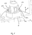
- This parting line is unproblematic in the event of a later water-guiding function, as it is then anyway in an area that is entirely filled with water, cf. Figure 6 for illustration.
- a further locking lug is preferably also provided on the pin, preferably rotationally symmetrical to the first about the axis of rotation. Precisely two locking lugs which are rotationally symmetrical to one another by 180 ° are particularly preferred.
- a groove is formed in an inner wall surface delimiting the outlet channel, in which groove the projection is guided when it is pushed in. If it is arranged in the groove during insertion, a rotational movement is blocked; it is released when the pin is in the insertion position, the projection then lies outside the groove.
- a seal which seals the inserted drain unit against the part of the passage (preferably the closure) that forms the drain channel.
- a molded seal is also possible, for example a seal molded onto the closure or the drain unit by multi-component injection molding.
- a multi-part seal for the outlet unit and the part of the passage forming the outlet channel is preferred, in particular a sealing ring, which is particularly preferably placed on the pin of the outlet unit and can be secured against slipping down, for example, by a projection and / or locking lug.
- the seal can be of interest not only because of the sealing function, but also with regard to a spring function, see above.
- the outlet unit has a hose connection, preferably a connection piece, which can in particular be ribbed on the outside.
- a hose can be placed on this and, for example, laid outside the technical building / transformer station.
- the hose can be secured on the connecting piece with a clamp, for example.
- a connected hose can preferably be provided with a fitting, in the simplest case with a pinch valve.
- a hose is preferably already connected when the drain unit is inserted, the drain unit further preferably being designed to be intrinsically conductive in terms of pressure fluid, that is to say functionally represents a pipe section.
- a drain unit with an actuatable fitting would also be possible, for example a stopcock or stop valve. In this case, the drainage unit could also be introduced first and then the hose connected.
- the hose connection preferably extends away from the pin at an angle, in particular perpendicular, to the axis of rotation.
- the design as an (especially angled) pipe section can result in a simple and thus inexpensive, but at the same time robust solution, which can also be of interest with regard to the hammering.
- the angled hose connection can also be advantageous because an end face area that is aligned with the pin in the direction of insertion can be used as a striking surface without the hose connection being at risk of damage.
- the closure can be reversibly removed from the tubular element and reinserted, for example screwable.
- a combined insertion / rotation mechanism in particular with a bayonet lock, is preferred.
- the closure can then be released again, for example by a combined pressing and turning in the opposite direction, and removed from the tubular element.
- a plurality of outlet channels are preferably arranged in the reversibly removable closure, that is to say at least 2, further and particularly preferably at least 3 or 4 outlet channels (with possible upper limits of, for example, at most 12, 10 or 8).
- Each of the outlet channels is preferably designed in a manner disclosed in the present case, in particular each equipped with a blind plug, etc.
- Several outlet channels can initially help prevent assembly errors because a plug provided with only one eccentric outlet channel in the event of incorrect assembly (drainage duct "above"), only partial emptying is permitted. In the construction phase in which the lock is used, this problem is often not foreseeable or known because, for example, a concrete worker places the bushing and thus the lock, whereas the lock has to be removed by an electrician, for example, much later.
- the outlet channels provided in a plurality can also represent depressions into which one can reach by hand when inserting or removing the closure.
- the closure is preferably formed in some areas from an at least translucent material, so that before the removal of the closure on one side thereof, water present on the opposite side can be visually recognized.
- the material is “at least translucent”, that is to say at least partially translucent; it is preferably transparent, that is to say permeable to the image / view.
- the closure can also be designed to be translucent / transparent in only one area, ie it can have a type of viewing window; it could, for example, represent such a viewing window.
- an overall at least translucent or transparent closure is preferred, which on the one hand can be advantageous in terms of production technology and on the other hand can make water that is present reliably recognizable.
- the water is usually not clear, but rather cloudy due to soiling etc. and can therefore be easily recognized.
- water can also be detected without the at least translucent area, for example by the fitter knocking against it before removing the cover and can deduce a volume of air from a hollow sound.
- a suspension element is provided on the outside of the tubular element, preferably at one end of the tubular element, for fastening the implementation during installation in the wall or floor element.
- This suspension element is preferably provided as a circumferential flange plate that rises away from the tubular element perpendicular to the longitudinal direction, particularly preferably as a flat plate arranged at one end of the tubular element Flange plate.
- the suspension element preferably has a polygonal outer contour, so that it can be assembled in a two-dimensional manner with correspondingly polygonal suspension elements of further passages.
- An essentially rectangular, in particular square, outer contour is preferred.
- the suspension element has a connecting element via which the bushing can be connected to a further bushing.
- This connecting element is preferably a form-locking element provided twice as a first and a second complementary thereto, so that when two passages are put together, the first form-locking element of one passage forms a form-fit connection with the second form-locking element of the other passage, and vice versa.
- the form-fit elements can engage in one another like a tongue and groove, preferably with an undercut; the assembly and disassembly of the form-fit elements is preferably carried out with a respective movement perpendicular to the longitudinal direction.
- the invention also relates to a method for draining water, in particular from an implementation discussed above.
- a pipe element of the bushing does not necessarily have to keep the passage opening in the wall or floor element free; this could, for example, also be made as a core hole or, when pouring concrete, it could have been kept free by a molded part / pipe element that was later removed .
- B. on the one hand can be a blind cover arranged in a pipe element (see above), but on the other hand, for example, also a press seal, which is set in a core hole, for example.
- a press seal is made up of an elastomer body, on the two end faces of which there are arranged press bodies connected to one another via clamping bolts, which are moved towards one another by tightening the clamping bolts and thus axially compress the elastomer body, which as a result of this is in any case sealing radially outwards (if necessary also after inside if the line is carried out).
- water is now arranged on one side thereof, and a protective tube, in which the water has collected, is preferably connected to the passage opening on this side.
- the passage opening up to the closure can also be completely filled with water and this can also be present in hilly terrain with pressure, for example with up to 5 bar, 4 bar, 3 bar or 2 bar.
- this water is drained from the other side through a passage opening with a limited cross-section; in this respect reference is expressly made to the above disclosure, the information given there on the tubular element and its cross section being equally applicable to the through opening and its cross section.
- the closure can advantageously be removed from the through opening and a line, for example, can be passed through.
- the invention also relates to the use of a bushing without a drain unit together with a drain unit in a manner described here for a bushing with a drain unit or for such a bushing.
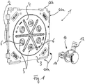
- Figure 1 shows a use according to the invention of a bushing 1 with a tubular element 2, which in the oblique view according to FIG Figure 1 is largely covered by a flange plate 3 designed monolithically therewith, but for example in the side view according to FIG Figure 4 is clearly visible. Furthermore, a closure 4 is provided, which is inserted as a blind cover into the tubular element 2 and closes it, for example, during a construction phase. In the present case, the closure 4 used is held in the tubular element 2 by means of a bayonet lock and, based on FIG Figure 1 can be released by turning to the left (combined with a slight pressure) and then removed from the tubular element 2.
- the closure 4 is used during a construction phase.
- the flange plate 3 is nailed to the formwork provided for this purpose and the pipe element 2 then keeps a through opening in the concrete free.
- the pipe element 2 does not usually extend by itself over the entire wall thickness, but a further pipe section (not shown) can be attached to extend it (for example in the illustration according to FIG Fig. 2 is inserted from the left into the tubular element 2).
- a protective tube can then be attached to the outside of the building (also not shown), in which the actual line, e.g. B. an electric cable is performed.
- This protective pipe is or will be laid in a trench in the ground, which is then filled in again before the actual line is laid.
- the representation according to Figure 2 can therefore connect to the left of the pipe element 2 a pipe section which is still arranged within the wall and which is followed by the protective pipe extending in the ground.
- Fig. 1 basically reproduces what the fitter who is supposed to lay the electrical cable, for example, finds when he looks at the wall (not shown) from inside the building. Has now in the pipe element 2 with the connected pipe system z. If rainwater is collected, for example, it would run into the building in an uncontrolled manner when the closure was removed, sometimes even under high pressure (in the case of a protective pipe with a gradient, see also the introduction to the description).
- the closure 4 is designed to be transparent so that any water present can be determined by visual inspection.
- drainage channels 5 are provided in the closure 4, distributed around the circumference, which in the initial state are each still closed by a blind closure 6.
- the blind closures 6 are each formed monolithically with the rest of the closure 4 from the same material, in the present case from polycarbonate.
- an outlet unit 10 is provided which, as a hollow body, functionally represents an L-shaped pipe section.
- the drain unit 10 has a pin 11 with which it is pushed into the corresponding drain channel 5 and in the process ejects the blind cap 6.
- the drain unit 10 is hammered in with a striking tool, for example a hammer.
- the drain unit 10 has a hose connection 12 onto which a hose, not shown here, is placed.
- the hose can already be attached, but it can still be blocked, for example, with a clamp as a squeeze flange. If the blind plug 6 is then ejected and the drain unit 10 is locked in the drain channel 5 (see below in detail), the hose can be laid outside the building or to a drain and the water located in the pipe element 2 can be drained.
- the closure 4 can then be removed and, for example, an electrical cable can be laid through the pipe element 2 and the connected pipe system.
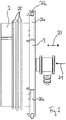
- Figure 2 shows the bushing 1 with the outlet unit 10 inserted, specifically looking at it perpendicular to a longitudinal direction 20 of the tubular element (based on FIG Figure 1 from underneath).
- the discharge unit 10 is pushed into the discharge channel in an insertion direction 21, that is to say in Figure 2 to the left.
- Figure 2 also shows a multiple web seal 25, which is made of acrylic-butadiene-styrene (ABS) and is enclosed by the concrete, injected onto the outside of the pipe element 2 in a two-component injection molding process from a thermoplastic elastomer (TPE).
- form-locking elements 26 arranged on the flange plate 3 can be seen, which are spring-shaped 26a or groove-like 26b, cf. also the oblique view according to FIG Figure 1 .
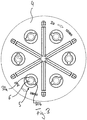
- FIG. 3 shows the closure 4 in a plan view, that is, looking at it along the direction of insertion.
- the discharge channel 5 is here still closed with the blind closure 6 (the latter merges into the rest of the closure 4 via a predetermined breaking point not shown here).
- two grooves 30a, b are provided which extend in the direction of insertion and in which projections 11a, b provided on the outside of the pin 11 are guided when the pin 11 is inserted (see FIG Fig. 4 compared).
- a rotary movement of the pin 11 is blocked due to this guide, but the drain unit 10 can then be in an in Figure 6
- the shown insertion position can be rotated and thus locked.
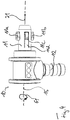
- the pin 11 also has two locking lugs as a locking mechanism, of which in the view according to FIG Figure 4 only one front is visible and the other is covered. If the pin 11 is pushed into the outlet channel 5, that is to say in a straight line with a striking tool, in particular a hammer, the locking lugs lock before the subsequent rotation lock. During the insertion, the latching lugs are pressed inward by a wall surface delimiting the outlet channel 5, that is to say radially inward towards an axis of rotation 25. As can be seen for the front locking lug, this is resiliently mounted on a tongue 11d for this purpose, which is formed by a separating joint that is not closed in itself (but which completely penetrates the wall of the pin).
- the subsequent rotation lock is provided by the projections 11a, b, which are then initially guided on a rising guide surface 31a, b with the rotary movement about the axis of rotation 15, see also FIG Figures 5 and 6th .
- the projections 11a, b guided in this way pull the pin 11 into its seat in the drainage channel 5, against the spring force of an in Figure 6 shown sealing ring 60.
- After hammering in and thus opening the blind cap - Figure 5 shows the drainage channel 5 without a blind plug - that is, they first secure the locking lugs against slipping out, but there can still be a leak, especially when the water is under high pressure. This is canceled with the rotation lock and thus the compression of the sealing ring 60.
- Figure 6 further illustrates that in the direction of rotation 61 each of the guide surfaces 30a, b is followed by a recess surface 62a, b into which the respective projection 11a, b slides a little.
- the recess surfaces 62 a, b are therefore each set back with respect to an end section of the respective guide surface 31 a, b.
- the projections are then secured against undesired unscrewing, the pin 11 must first be pressed a little against the spring force of the sealing ring 60 to unscrew in order to lift the projections 11a, b from the respective recess surface 62a, b.
Landscapes
- Engineering & Computer Science (AREA)
- Architecture (AREA)
- General Engineering & Computer Science (AREA)
- Civil Engineering (AREA)
- Structural Engineering (AREA)
- Mechanical Engineering (AREA)
- Quick-Acting Or Multi-Walled Pipe Joints (AREA)
Priority Applications (2)
| Application Number | Priority Date | Filing Date | Title |
|---|---|---|---|
| EP17020216.2A EP3404170B1 (de) | 2017-05-18 | 2017-05-18 | Verwendung einer durchführung zum einbau in ein wand- oder bodenelement |
| PL17020216T PL3404170T3 (pl) | 2017-05-18 | 2017-05-18 | Zastosowanie przepustu do montażu w elemencie ściennym lub podłogowym |
Applications Claiming Priority (1)
| Application Number | Priority Date | Filing Date | Title |
|---|---|---|---|
| EP17020216.2A EP3404170B1 (de) | 2017-05-18 | 2017-05-18 | Verwendung einer durchführung zum einbau in ein wand- oder bodenelement |
Publications (2)
| Publication Number | Publication Date |
|---|---|
| EP3404170A1 EP3404170A1 (de) | 2018-11-21 |
| EP3404170B1 true EP3404170B1 (de) | 2021-05-05 |
Family
ID=58744962
Family Applications (1)
| Application Number | Title | Priority Date | Filing Date |
|---|---|---|---|
| EP17020216.2A Active EP3404170B1 (de) | 2017-05-18 | 2017-05-18 | Verwendung einer durchführung zum einbau in ein wand- oder bodenelement |
Country Status (2)
| Country | Link |
|---|---|
| EP (1) | EP3404170B1 (pl) |
| PL (1) | PL3404170T3 (pl) |
Citations (2)
| Publication number | Priority date | Publication date | Assignee | Title |
|---|---|---|---|---|
| EP2511580A1 (de) * | 2011-03-21 | 2012-10-17 | Hauff-Technik GmbH & Co. KG | Durchführung zum Einbau in ein Wand- oder Bodenelement |
| EP3012501A1 (de) * | 2014-10-24 | 2016-04-27 | Hauff-Technik GmbH & Co. KG | Durchführung zum Einbau in ein Wand- oder Bodenelement |
Family Cites Families (2)
| Publication number | Priority date | Publication date | Assignee | Title |
|---|---|---|---|---|
| US5711536A (en) * | 1994-05-11 | 1998-01-27 | Tuf-Tite, Inc. | Seal component for use in on-site poured concrete or plastic tank or box components of fluid distribution systems |
| US6029981A (en) * | 1997-04-21 | 2000-02-29 | Form Rite Corporation | Tube plug seal |
-
2017
- 2017-05-18 PL PL17020216T patent/PL3404170T3/pl unknown
- 2017-05-18 EP EP17020216.2A patent/EP3404170B1/de active Active
Patent Citations (2)
| Publication number | Priority date | Publication date | Assignee | Title |
|---|---|---|---|---|
| EP2511580A1 (de) * | 2011-03-21 | 2012-10-17 | Hauff-Technik GmbH & Co. KG | Durchführung zum Einbau in ein Wand- oder Bodenelement |
| EP3012501A1 (de) * | 2014-10-24 | 2016-04-27 | Hauff-Technik GmbH & Co. KG | Durchführung zum Einbau in ein Wand- oder Bodenelement |
Also Published As
| Publication number | Publication date |
|---|---|
| PL3404170T3 (pl) | 2021-09-13 |
| EP3404170A1 (de) | 2018-11-21 |
Similar Documents
| Publication | Publication Date | Title |
|---|---|---|
| EP2899332B1 (de) | Verwendung einer Durchführung zum Einbau in einem Wand- oder Bodenelement | |
| EP3026766B1 (de) | Rohreinführung für eine unterputzdose | |
| DE19531913A1 (de) | Anbohrarmatur für vorzugsweise unter Mediendruck stehende Versorgungsleitungen aus Kunststoff | |
| DE69203792T2 (de) | Vorrichtung zum abgedichteten Verbinden von rohrförmigen Elementen an Abzweigdosen für elektrische Komponenten. | |
| DE3831611C2 (de) | Verfahren zur Herstellung einer Übergangskupplung aus einem Metallrohr und einem Kunststoffrohr mit einer Muffe | |
| EP3288130B1 (de) | Verwendung einer gebäudeeinführung zum einbau in eine gebäudeaussenwand | |
| EP3404170B1 (de) | Verwendung einer durchführung zum einbau in ein wand- oder bodenelement | |
| EP2631370A2 (de) | Unterflur-Schacht | |
| WO2015022272A1 (de) | Absperrventilgehäuse und absperrventil | |
| DE202017002654U1 (de) | Durchführung zum Einbau in ein Wand- oder Bodenelement | |
| DE10346463B4 (de) | System zum Durchführen wenigstens eines Kabels oder eines Leitungsrohres durch eine Gebäudewand | |
| DE102020001141A1 (de) | Durchführungsanordnung zum Einbau in ein Wand- oder Bodenelement | |
| EP3168375A1 (de) | Wandarmatur | |
| EP2194212A1 (de) | Schalungskasten | |
| EP3061890B1 (de) | Durchführung zum Vergießen mit Beton | |
| DE8615929U1 (de) | Abdichtung für eine Rohrdurchführung | |
| DE10045242C2 (de) | Einputzhilfe, Blinddeckel sowie Rohrleitungsanschlußstück | |
| DE202015001458U1 (de) | Durchführung zum Vergießen mit Beton | |
| EP3530999B1 (de) | Pressdichtungssystem | |
| AT413778B (de) | Einbaudose für die betonbauinstallation | |
| EP3012501B1 (de) | Durchführung zum einbau in ein wand- oder bodenelement | |
| DE202018000959U1 (de) | Pressdichtungssystem | |
| DE2908836A1 (de) | Mauerdurchfuehrung fuer elektrische leitungskabel | |
| EP3369977A1 (de) | Pressdichtungssystem zum abdichten gegen eine leitung | |
| DE102014019424A1 (de) | Ultraschallzähler |
Legal Events
| Date | Code | Title | Description |
|---|---|---|---|
| PUAI | Public reference made under article 153(3) epc to a published international application that has entered the european phase |
Free format text: ORIGINAL CODE: 0009012 |
|
| STAA | Information on the status of an ep patent application or granted ep patent |
Free format text: STATUS: REQUEST FOR EXAMINATION WAS MADE |
|
| 17P | Request for examination filed |
Effective date: 20180806 |
|
| AK | Designated contracting states |
Kind code of ref document: A1 Designated state(s): AL AT BE BG CH CY CZ DE DK EE ES FI FR GB GR HR HU IE IS IT LI LT LU LV MC MK MT NL NO PL PT RO RS SE SI SK SM TR |
|
| AX | Request for extension of the european patent |
Extension state: BA ME |
|
| RBV | Designated contracting states (corrected) |
Designated state(s): AL AT BE BG CH CY CZ DE DK EE ES FI FR GB GR HR HU IE IS IT LI LT LU LV MC MK MT NL NO PL PT RO RS SE SI SK SM TR |
|
| STAA | Information on the status of an ep patent application or granted ep patent |
Free format text: STATUS: EXAMINATION IS IN PROGRESS |
|
| 17Q | First examination report despatched |
Effective date: 20190820 |
|
| GRAP | Despatch of communication of intention to grant a patent |
Free format text: ORIGINAL CODE: EPIDOSNIGR1 |
|
| STAA | Information on the status of an ep patent application or granted ep patent |
Free format text: STATUS: GRANT OF PATENT IS INTENDED |
|
| INTG | Intention to grant announced |
Effective date: 20210203 |
|
| GRAS | Grant fee paid |
Free format text: ORIGINAL CODE: EPIDOSNIGR3 |
|
| GRAA | (expected) grant |
Free format text: ORIGINAL CODE: 0009210 |
|
| STAA | Information on the status of an ep patent application or granted ep patent |
Free format text: STATUS: THE PATENT HAS BEEN GRANTED |
|
| AK | Designated contracting states |
Kind code of ref document: B1 Designated state(s): AL AT BE BG CH CY CZ DE DK EE ES FI FR GB GR HR HU IE IS IT LI LT LU LV MC MK MT NL NO PL PT RO RS SE SI SK SM TR |
|
| REG | Reference to a national code |
Ref country code: GB Ref legal event code: FG4D Free format text: NOT ENGLISH |
|
| REG | Reference to a national code |
Ref country code: CH Ref legal event code: EP Ref country code: CH Ref legal event code: NV Representative=s name: TR-IP CONSULTING LLC, CH |
|
| REG | Reference to a national code |
Ref country code: AT Ref legal event code: REF Ref document number: 1389989 Country of ref document: AT Kind code of ref document: T Effective date: 20210515 |
|
| REG | Reference to a national code |
Ref country code: IE Ref legal event code: FG4D Free format text: LANGUAGE OF EP DOCUMENT: GERMAN |
|
| REG | Reference to a national code |
Ref country code: DE Ref legal event code: R096 Ref document number: 502017010247 Country of ref document: DE |
|
| REG | Reference to a national code |
Ref country code: NL Ref legal event code: FP |
|
| REG | Reference to a national code |
Ref country code: LT Ref legal event code: MG9D |
|
| PG25 | Lapsed in a contracting state [announced via postgrant information from national office to epo] |
Ref country code: FI Free format text: LAPSE BECAUSE OF FAILURE TO SUBMIT A TRANSLATION OF THE DESCRIPTION OR TO PAY THE FEE WITHIN THE PRESCRIBED TIME-LIMIT Effective date: 20210505 Ref country code: LT Free format text: LAPSE BECAUSE OF FAILURE TO SUBMIT A TRANSLATION OF THE DESCRIPTION OR TO PAY THE FEE WITHIN THE PRESCRIBED TIME-LIMIT Effective date: 20210505 Ref country code: BG Free format text: LAPSE BECAUSE OF FAILURE TO SUBMIT A TRANSLATION OF THE DESCRIPTION OR TO PAY THE FEE WITHIN THE PRESCRIBED TIME-LIMIT Effective date: 20210805 Ref country code: HR Free format text: LAPSE BECAUSE OF FAILURE TO SUBMIT A TRANSLATION OF THE DESCRIPTION OR TO PAY THE FEE WITHIN THE PRESCRIBED TIME-LIMIT Effective date: 20210505 |
|
| PG25 | Lapsed in a contracting state [announced via postgrant information from national office to epo] |
Ref country code: PT Free format text: LAPSE BECAUSE OF FAILURE TO SUBMIT A TRANSLATION OF THE DESCRIPTION OR TO PAY THE FEE WITHIN THE PRESCRIBED TIME-LIMIT Effective date: 20210906 Ref country code: NO Free format text: LAPSE BECAUSE OF FAILURE TO SUBMIT A TRANSLATION OF THE DESCRIPTION OR TO PAY THE FEE WITHIN THE PRESCRIBED TIME-LIMIT Effective date: 20210805 Ref country code: RS Free format text: LAPSE BECAUSE OF FAILURE TO SUBMIT A TRANSLATION OF THE DESCRIPTION OR TO PAY THE FEE WITHIN THE PRESCRIBED TIME-LIMIT Effective date: 20210505 Ref country code: SE Free format text: LAPSE BECAUSE OF FAILURE TO SUBMIT A TRANSLATION OF THE DESCRIPTION OR TO PAY THE FEE WITHIN THE PRESCRIBED TIME-LIMIT Effective date: 20210505 Ref country code: LV Free format text: LAPSE BECAUSE OF FAILURE TO SUBMIT A TRANSLATION OF THE DESCRIPTION OR TO PAY THE FEE WITHIN THE PRESCRIBED TIME-LIMIT Effective date: 20210505 Ref country code: GR Free format text: LAPSE BECAUSE OF FAILURE TO SUBMIT A TRANSLATION OF THE DESCRIPTION OR TO PAY THE FEE WITHIN THE PRESCRIBED TIME-LIMIT Effective date: 20210806 Ref country code: IS Free format text: LAPSE BECAUSE OF FAILURE TO SUBMIT A TRANSLATION OF THE DESCRIPTION OR TO PAY THE FEE WITHIN THE PRESCRIBED TIME-LIMIT Effective date: 20210905 |
|
| PG25 | Lapsed in a contracting state [announced via postgrant information from national office to epo] |
Ref country code: SM Free format text: LAPSE BECAUSE OF FAILURE TO SUBMIT A TRANSLATION OF THE DESCRIPTION OR TO PAY THE FEE WITHIN THE PRESCRIBED TIME-LIMIT Effective date: 20210505 Ref country code: SK Free format text: LAPSE BECAUSE OF FAILURE TO SUBMIT A TRANSLATION OF THE DESCRIPTION OR TO PAY THE FEE WITHIN THE PRESCRIBED TIME-LIMIT Effective date: 20210505 Ref country code: ES Free format text: LAPSE BECAUSE OF FAILURE TO SUBMIT A TRANSLATION OF THE DESCRIPTION OR TO PAY THE FEE WITHIN THE PRESCRIBED TIME-LIMIT Effective date: 20210505 Ref country code: RO Free format text: LAPSE BECAUSE OF FAILURE TO SUBMIT A TRANSLATION OF THE DESCRIPTION OR TO PAY THE FEE WITHIN THE PRESCRIBED TIME-LIMIT Effective date: 20210505 Ref country code: DK Free format text: LAPSE BECAUSE OF FAILURE TO SUBMIT A TRANSLATION OF THE DESCRIPTION OR TO PAY THE FEE WITHIN THE PRESCRIBED TIME-LIMIT Effective date: 20210505 Ref country code: EE Free format text: LAPSE BECAUSE OF FAILURE TO SUBMIT A TRANSLATION OF THE DESCRIPTION OR TO PAY THE FEE WITHIN THE PRESCRIBED TIME-LIMIT Effective date: 20210505 |
|
| REG | Reference to a national code |
Ref country code: DE Ref legal event code: R097 Ref document number: 502017010247 Country of ref document: DE |
|
| REG | Reference to a national code |
Ref country code: BE Ref legal event code: MM Effective date: 20210531 |
|
| PLBE | No opposition filed within time limit |
Free format text: ORIGINAL CODE: 0009261 |
|
| STAA | Information on the status of an ep patent application or granted ep patent |
Free format text: STATUS: NO OPPOSITION FILED WITHIN TIME LIMIT |
|
| PG25 | Lapsed in a contracting state [announced via postgrant information from national office to epo] |
Ref country code: MC Free format text: LAPSE BECAUSE OF FAILURE TO SUBMIT A TRANSLATION OF THE DESCRIPTION OR TO PAY THE FEE WITHIN THE PRESCRIBED TIME-LIMIT Effective date: 20210505 |
|
| 26N | No opposition filed |
Effective date: 20220208 |
|
| GBPC | Gb: european patent ceased through non-payment of renewal fee |
Effective date: 20210805 |
|
| PG25 | Lapsed in a contracting state [announced via postgrant information from national office to epo] |
Ref country code: IE Free format text: LAPSE BECAUSE OF NON-PAYMENT OF DUE FEES Effective date: 20210518 |
|
| PG25 | Lapsed in a contracting state [announced via postgrant information from national office to epo] |
Ref country code: IS Free format text: LAPSE BECAUSE OF FAILURE TO SUBMIT A TRANSLATION OF THE DESCRIPTION OR TO PAY THE FEE WITHIN THE PRESCRIBED TIME-LIMIT Effective date: 20210905 Ref country code: AL Free format text: LAPSE BECAUSE OF FAILURE TO SUBMIT A TRANSLATION OF THE DESCRIPTION OR TO PAY THE FEE WITHIN THE PRESCRIBED TIME-LIMIT Effective date: 20210505 |
|
| PGFP | Annual fee paid to national office [announced via postgrant information from national office to epo] |
Ref country code: NL Payment date: 20220518 Year of fee payment: 6 |
|
| PG25 | Lapsed in a contracting state [announced via postgrant information from national office to epo] |
Ref country code: IT Free format text: LAPSE BECAUSE OF FAILURE TO SUBMIT A TRANSLATION OF THE DESCRIPTION OR TO PAY THE FEE WITHIN THE PRESCRIBED TIME-LIMIT Effective date: 20210505 Ref country code: GB Free format text: LAPSE BECAUSE OF NON-PAYMENT OF DUE FEES Effective date: 20210805 Ref country code: BE Free format text: LAPSE BECAUSE OF NON-PAYMENT OF DUE FEES Effective date: 20210531 |
|
| PGFP | Annual fee paid to national office [announced via postgrant information from national office to epo] |
Ref country code: LU Payment date: 20220518 Year of fee payment: 6 Ref country code: FR Payment date: 20220523 Year of fee payment: 6 Ref country code: CZ Payment date: 20220505 Year of fee payment: 6 |
|
| PGFP | Annual fee paid to national office [announced via postgrant information from national office to epo] |
Ref country code: PL Payment date: 20220510 Year of fee payment: 6 |
|
| P01 | Opt-out of the competence of the unified patent court (upc) registered |
Effective date: 20230428 |
|
| PG25 | Lapsed in a contracting state [announced via postgrant information from national office to epo] |
Ref country code: CY Free format text: LAPSE BECAUSE OF FAILURE TO SUBMIT A TRANSLATION OF THE DESCRIPTION OR TO PAY THE FEE WITHIN THE PRESCRIBED TIME-LIMIT Effective date: 20210505 |
|
| PG25 | Lapsed in a contracting state [announced via postgrant information from national office to epo] |
Ref country code: HU Free format text: LAPSE BECAUSE OF FAILURE TO SUBMIT A TRANSLATION OF THE DESCRIPTION OR TO PAY THE FEE WITHIN THE PRESCRIBED TIME-LIMIT; INVALID AB INITIO Effective date: 20170518 |
|
| PGFP | Annual fee paid to national office [announced via postgrant information from national office to epo] |
Ref country code: CH Payment date: 20230602 Year of fee payment: 7 |
|
| PGFP | Annual fee paid to national office [announced via postgrant information from national office to epo] |
Ref country code: AT Payment date: 20230516 Year of fee payment: 7 |
|
| REG | Reference to a national code |
Ref country code: NL Ref legal event code: MM Effective date: 20230601 |
|
| PG25 | Lapsed in a contracting state [announced via postgrant information from national office to epo] |
Ref country code: LU Free format text: LAPSE BECAUSE OF NON-PAYMENT OF DUE FEES Effective date: 20230518 Ref country code: CZ Free format text: LAPSE BECAUSE OF NON-PAYMENT OF DUE FEES Effective date: 20230518 |
|
| PG25 | Lapsed in a contracting state [announced via postgrant information from national office to epo] |
Ref country code: NL Free format text: LAPSE BECAUSE OF NON-PAYMENT OF DUE FEES Effective date: 20230601 |
|
| PG25 | Lapsed in a contracting state [announced via postgrant information from national office to epo] |
Ref country code: MK Free format text: LAPSE BECAUSE OF FAILURE TO SUBMIT A TRANSLATION OF THE DESCRIPTION OR TO PAY THE FEE WITHIN THE PRESCRIBED TIME-LIMIT Effective date: 20210505 |
|
| PG25 | Lapsed in a contracting state [announced via postgrant information from national office to epo] |
Ref country code: FR Free format text: LAPSE BECAUSE OF NON-PAYMENT OF DUE FEES Effective date: 20230531 |
|
| PG25 | Lapsed in a contracting state [announced via postgrant information from national office to epo] |
Ref country code: MT Free format text: LAPSE BECAUSE OF FAILURE TO SUBMIT A TRANSLATION OF THE DESCRIPTION OR TO PAY THE FEE WITHIN THE PRESCRIBED TIME-LIMIT Effective date: 20210505 |
|
| REG | Reference to a national code |
Ref country code: CH Ref legal event code: PL |
|
| REG | Reference to a national code |
Ref country code: AT Ref legal event code: MM01 Ref document number: 1389989 Country of ref document: AT Kind code of ref document: T Effective date: 20240518 |
|
| PG25 | Lapsed in a contracting state [announced via postgrant information from national office to epo] |
Ref country code: PL Free format text: LAPSE BECAUSE OF NON-PAYMENT OF DUE FEES Effective date: 20230518 |
|
| PG25 | Lapsed in a contracting state [announced via postgrant information from national office to epo] |
Ref country code: AT Free format text: LAPSE BECAUSE OF NON-PAYMENT OF DUE FEES Effective date: 20240518 |
|
| PG25 | Lapsed in a contracting state [announced via postgrant information from national office to epo] |
Ref country code: PL Free format text: LAPSE BECAUSE OF NON-PAYMENT OF DUE FEES Effective date: 20230518 Ref country code: AT Free format text: LAPSE BECAUSE OF NON-PAYMENT OF DUE FEES Effective date: 20240518 Ref country code: CH Free format text: LAPSE BECAUSE OF NON-PAYMENT OF DUE FEES Effective date: 20240531 |
|
| REG | Reference to a national code |
Ref country code: DE Ref legal event code: R082 Ref document number: 502017010247 Country of ref document: DE Representative=s name: SZYNKA SMORODIN PATENTANWAELTE PARTNERSCHAFT M, DE |
|
| PGFP | Annual fee paid to national office [announced via postgrant information from national office to epo] |
Ref country code: DE Payment date: 20250519 Year of fee payment: 9 |
|
| REG | Reference to a national code |
Ref country code: CH Ref legal event code: R17 Free format text: ST27 STATUS EVENT CODE: U-0-0-R10-R17 (AS PROVIDED BY THE NATIONAL OFFICE) Effective date: 20251028 |
|
| PG25 | Lapsed in a contracting state [announced via postgrant information from national office to epo] |
Ref country code: TR Free format text: LAPSE BECAUSE OF FAILURE TO SUBMIT A TRANSLATION OF THE DESCRIPTION OR TO PAY THE FEE WITHIN THE PRESCRIBED TIME-LIMIT Effective date: 20210505 |