EP3403739B1 - Flexibles rohr - Google Patents
Flexibles rohr Download PDFInfo
- Publication number
- EP3403739B1 EP3403739B1 EP18177456.3A EP18177456A EP3403739B1 EP 3403739 B1 EP3403739 B1 EP 3403739B1 EP 18177456 A EP18177456 A EP 18177456A EP 3403739 B1 EP3403739 B1 EP 3403739B1
- Authority
- EP
- European Patent Office
- Prior art keywords
- flexible pipe
- wing
- pipe body
- layer
- tape element
- Prior art date
- Legal status (The legal status is an assumption and is not a legal conclusion. Google has not performed a legal analysis and makes no representation as to the accuracy of the status listed.)
- Active
Links
Images


Classifications
-
- F—MECHANICAL ENGINEERING; LIGHTING; HEATING; WEAPONS; BLASTING
- F16—ENGINEERING ELEMENTS AND UNITS; GENERAL MEASURES FOR PRODUCING AND MAINTAINING EFFECTIVE FUNCTIONING OF MACHINES OR INSTALLATIONS; THERMAL INSULATION IN GENERAL
- F16L—PIPES; JOINTS OR FITTINGS FOR PIPES; SUPPORTS FOR PIPES, CABLES OR PROTECTIVE TUBING; MEANS FOR THERMAL INSULATION IN GENERAL
- F16L11/00—Hoses, i.e. flexible pipes
- F16L11/14—Hoses, i.e. flexible pipes made of rigid material, e.g. metal or hard plastics
-
- B—PERFORMING OPERATIONS; TRANSPORTING
- B21—MECHANICAL METAL-WORKING WITHOUT ESSENTIALLY REMOVING MATERIAL; PUNCHING METAL
- B21C—MANUFACTURE OF METAL SHEETS, WIRE, RODS, TUBES, PROFILES OR LIKE SEMI-MANUFACTURED PRODUCTS OTHERWISE THAN BY ROLLING; AUXILIARY OPERATIONS USED IN CONNECTION WITH METAL-WORKING WITHOUT ESSENTIALLY REMOVING MATERIAL
- B21C37/00—Manufacture of metal sheets, rods, wire, tubes, profiles or like semi-manufactured products, not otherwise provided for; Manufacture of tubes of special shape
- B21C37/06—Manufacture of metal sheets, rods, wire, tubes, profiles or like semi-manufactured products, not otherwise provided for; Manufacture of tubes of special shape of tubes or metal hoses; Combined procedures for making tubes, e.g. for making multi-wall tubes
- B21C37/12—Making tubes or metal hoses with helically arranged seams
- B21C37/121—Making tubes or metal hoses with helically arranged seams with seams being neither welded nor soldered
-
- B—PERFORMING OPERATIONS; TRANSPORTING
- B21—MECHANICAL METAL-WORKING WITHOUT ESSENTIALLY REMOVING MATERIAL; PUNCHING METAL
- B21C—MANUFACTURE OF METAL SHEETS, WIRE, RODS, TUBES, PROFILES OR LIKE SEMI-MANUFACTURED PRODUCTS OTHERWISE THAN BY ROLLING; AUXILIARY OPERATIONS USED IN CONNECTION WITH METAL-WORKING WITHOUT ESSENTIALLY REMOVING MATERIAL
- B21C37/00—Manufacture of metal sheets, rods, wire, tubes, profiles or like semi-manufactured products, not otherwise provided for; Manufacture of tubes of special shape
- B21C37/06—Manufacture of metal sheets, rods, wire, tubes, profiles or like semi-manufactured products, not otherwise provided for; Manufacture of tubes of special shape of tubes or metal hoses; Combined procedures for making tubes, e.g. for making multi-wall tubes
- B21C37/12—Making tubes or metal hoses with helically arranged seams
- B21C37/124—Making tubes or metal hoses with helically arranged seams the tubes having a special shape, e.g. with corrugated wall, flexible tubes
-
- B—PERFORMING OPERATIONS; TRANSPORTING
- B21—MECHANICAL METAL-WORKING WITHOUT ESSENTIALLY REMOVING MATERIAL; PUNCHING METAL
- B21C—MANUFACTURE OF METAL SHEETS, WIRE, RODS, TUBES, PROFILES OR LIKE SEMI-MANUFACTURED PRODUCTS OTHERWISE THAN BY ROLLING; AUXILIARY OPERATIONS USED IN CONNECTION WITH METAL-WORKING WITHOUT ESSENTIALLY REMOVING MATERIAL
- B21C37/00—Manufacture of metal sheets, rods, wire, tubes, profiles or like semi-manufactured products, not otherwise provided for; Manufacture of tubes of special shape
- B21C37/06—Manufacture of metal sheets, rods, wire, tubes, profiles or like semi-manufactured products, not otherwise provided for; Manufacture of tubes of special shape of tubes or metal hoses; Combined procedures for making tubes, e.g. for making multi-wall tubes
- B21C37/12—Making tubes or metal hoses with helically arranged seams
- B21C37/126—Supply, or operations combined with supply, of strip material
-
- B—PERFORMING OPERATIONS; TRANSPORTING
- B29—WORKING OF PLASTICS; WORKING OF SUBSTANCES IN A PLASTIC STATE IN GENERAL
- B29C—SHAPING OR JOINING OF PLASTICS; SHAPING OF MATERIAL IN A PLASTIC STATE, NOT OTHERWISE PROVIDED FOR; AFTER-TREATMENT OF THE SHAPED PRODUCTS, e.g. REPAIRING
- B29C53/00—Shaping by bending, folding, twisting, straightening or flattening; Apparatus therefor
- B29C53/02—Bending or folding
- B29C53/04—Bending or folding of plates or sheets
- B29C53/043—Bending or folding of plates or sheets using rolls or endless belts
-
- F—MECHANICAL ENGINEERING; LIGHTING; HEATING; WEAPONS; BLASTING
- F16—ENGINEERING ELEMENTS AND UNITS; GENERAL MEASURES FOR PRODUCING AND MAINTAINING EFFECTIVE FUNCTIONING OF MACHINES OR INSTALLATIONS; THERMAL INSULATION IN GENERAL
- F16L—PIPES; JOINTS OR FITTINGS FOR PIPES; SUPPORTS FOR PIPES, CABLES OR PROTECTIVE TUBING; MEANS FOR THERMAL INSULATION IN GENERAL
- F16L11/00—Hoses, i.e. flexible pipes
- F16L11/04—Hoses, i.e. flexible pipes made of rubber or flexible plastics
- F16L11/08—Hoses, i.e. flexible pipes made of rubber or flexible plastics with reinforcements embedded in the wall
- F16L11/081—Hoses, i.e. flexible pipes made of rubber or flexible plastics with reinforcements embedded in the wall comprising one or more layers of a helically wound cord or wire
- F16L11/082—Hoses, i.e. flexible pipes made of rubber or flexible plastics with reinforcements embedded in the wall comprising one or more layers of a helically wound cord or wire two layers
-
- F—MECHANICAL ENGINEERING; LIGHTING; HEATING; WEAPONS; BLASTING
- F16—ENGINEERING ELEMENTS AND UNITS; GENERAL MEASURES FOR PRODUCING AND MAINTAINING EFFECTIVE FUNCTIONING OF MACHINES OR INSTALLATIONS; THERMAL INSULATION IN GENERAL
- F16L—PIPES; JOINTS OR FITTINGS FOR PIPES; SUPPORTS FOR PIPES, CABLES OR PROTECTIVE TUBING; MEANS FOR THERMAL INSULATION IN GENERAL
- F16L11/00—Hoses, i.e. flexible pipes
- F16L11/04—Hoses, i.e. flexible pipes made of rubber or flexible plastics
- F16L11/08—Hoses, i.e. flexible pipes made of rubber or flexible plastics with reinforcements embedded in the wall
- F16L11/081—Hoses, i.e. flexible pipes made of rubber or flexible plastics with reinforcements embedded in the wall comprising one or more layers of a helically wound cord or wire
- F16L11/083—Hoses, i.e. flexible pipes made of rubber or flexible plastics with reinforcements embedded in the wall comprising one or more layers of a helically wound cord or wire three or more layers
-
- F—MECHANICAL ENGINEERING; LIGHTING; HEATING; WEAPONS; BLASTING
- F16—ENGINEERING ELEMENTS AND UNITS; GENERAL MEASURES FOR PRODUCING AND MAINTAINING EFFECTIVE FUNCTIONING OF MACHINES OR INSTALLATIONS; THERMAL INSULATION IN GENERAL
- F16L—PIPES; JOINTS OR FITTINGS FOR PIPES; SUPPORTS FOR PIPES, CABLES OR PROTECTIVE TUBING; MEANS FOR THERMAL INSULATION IN GENERAL
- F16L11/00—Hoses, i.e. flexible pipes
- F16L11/14—Hoses, i.e. flexible pipes made of rigid material, e.g. metal or hard plastics
- F16L11/16—Hoses, i.e. flexible pipes made of rigid material, e.g. metal or hard plastics wound from profiled strips or bands
-
- F—MECHANICAL ENGINEERING; LIGHTING; HEATING; WEAPONS; BLASTING
- F16—ENGINEERING ELEMENTS AND UNITS; GENERAL MEASURES FOR PRODUCING AND MAINTAINING EFFECTIVE FUNCTIONING OF MACHINES OR INSTALLATIONS; THERMAL INSULATION IN GENERAL
- F16L—PIPES; JOINTS OR FITTINGS FOR PIPES; SUPPORTS FOR PIPES, CABLES OR PROTECTIVE TUBING; MEANS FOR THERMAL INSULATION IN GENERAL
- F16L57/00—Protection of pipes or objects of similar shape against external or internal damage or wear
- F16L57/02—Protection of pipes or objects of similar shape against external or internal damage or wear against cracking or buckling
-
- B—PERFORMING OPERATIONS; TRANSPORTING
- B29—WORKING OF PLASTICS; WORKING OF SUBSTANCES IN A PLASTIC STATE IN GENERAL
- B29L—INDEXING SCHEME ASSOCIATED WITH SUBCLASS B29C, RELATING TO PARTICULAR ARTICLES
- B29L2009/00—Layered products
-
- B—PERFORMING OPERATIONS; TRANSPORTING
- B29—WORKING OF PLASTICS; WORKING OF SUBSTANCES IN A PLASTIC STATE IN GENERAL
- B29L—INDEXING SCHEME ASSOCIATED WITH SUBCLASS B29C, RELATING TO PARTICULAR ARTICLES
- B29L2023/00—Tubular articles
- B29L2023/22—Tubes or pipes, i.e. rigid
Definitions
- the present invention relates to an elongate tape element and method of forming flexible pipe body.
- the present invention relates to a tape element for use in forming a layer of a flexible pipe body.
- Flexible pipe is utilised to transport production fluids, such as oil and/or gas and/or water, from one location to another.
- Flexible pipe is particularly useful in connecting a sub-sea location (which may be deep underwater, say 1000 metres or more) to a sea level location.
- the pipe may have an internal diameter of typically up to around 0.6 metres(e.g. diameters may range from 0.05 m up to 0.6 m).
- Flexible pipe is generally formed as an assembly of flexible pipe body and one or more end fittings.
- the pipe body is typically formed as a combination of layered materials that form a pressure-containing conduit.
- the pipe structure allows large deflections without causing bending stresses that impair the pipe's functionality over its lifetime.
- the pipe body is generally built up as a combined structure including polymer layers and/or composite layers and/or metallic layers.
- a pipe body may include polymer and metal layers, or polymer and composite layers, or polymer, metal and composite layers.
- the pipe body includes one or more pressure resistant layers.
- the primary load on such layers is formed from radial forces.
- pressure armour layers often have a specific cross section profile to interlock so as to be able to maintain and absorb radial forces resulting from outer or inner pressure on the pipe.
- the cross sectional profile of the wound wires which thus prevent the pipe from collapsing or bursting as a result of pressure are sometimes called pressure-resistant profiles.
- pressure armour layers are formed from helically wound wired forming hoop components, the radial forces from outer or inner pressure on the pipe cause the hoop components to expand or contract, putting a tensile load on the wires.
- Unbonded flexible pipe has been used for deep water (less than 3,300 feet (1,005.84 metres)) and ultra deep water (greater than 3,300 feet) developments. It is the increasing demand for oil which is causing exploration to occur at greater and greater depths where environmental factors are more extreme. For example in such deep and ultra-deep water environments ocean floor temperature increases the risk of production fluids cooling to a temperature that may lead to pipe blockage. Increased depths also increase the pressure associated with the environment in which the flexible pipe must operate. For example, a flexible pipe may be required to operate with external pressures ranging from 0.1 MPa to 30 MPa acting on the pipe.
- Flexible pipe may also be used for shallow water applications (for example less than around 500 metres depth) or even for shore (overland) applications.
- One way to improve the load response and thus performance of armour layers is to manufacture the layers from thicker and stronger and thus more robust materials.
- manufacturing the wires from thicker material results in the strength increasing appropriately.
- the weight of the flexible pipe increases.
- the weight of the flexible pipe can become a limiting factor in using flexible pipe.
- manufacturing flexible pipe using thicker and thicker material increases material costs appreciably, which is also a disadvantage.
- a pressure resistant layer is a carcass layer which helps prevent outer pressure collapsing a fluid retaining layer in the flexible pipe body.
- a carcass layer is thus a collapse resistant layer in the flexible pipe body.
- FLIP Flow Induced Pulsation
- layers adjacent to the pressure armour layer may become damaged, in particular when the material of the adjacent layer moves into gaps between adjacent windings of the pressure armour layer.
- US 2003/070719 discloses flexible metal tube having a box element and flexible pipe comprising such a metal tube comprising at least one strip wound helically about the axis, the strip having at least one closed box element, and wherein, to improve the anticreep function, it is possible to use a shaped wire to cover the interjoint spaces between two consecutive turns.
- flexible pipe body for transporting production fluid comprising a fluid retaining layer
- the flexible pipe body is formed with an elongate tape element for bridging a gap between windings of a flexible pipe body layer that interlock
- the tape element having a cross-sectional profile comprising: a body portion at least partially locatable in a gap between adjacent windings that interlock of a layer of a flexible pipe; a first wing portion extending from the body portion to a first wing end; and a further wing portion extending from the body portion to a further wing end; characterised in that the elongate tape element has a substantially uniform thickness across the cross-sectional profile.
- the flexible pipe body further comprises a carcass layer.
- each wing portion comprises a substantially flat inner surface region.
- the elongate tape element is helically windable between successive windings that provide said adjacent windings of a layer of a flexible pipe.
- first and further wing portions each extend from an end region of the body portion.
- each of the first and further wing portions is locatable to abut with an inner surface region of the adjacent windings.
- the first wing end comprises a first long edge of the tape element and the further wing end comprises a further long edge of the tape element.
- the cross-sectional profile of the elongate tape element only comprises: the first wing portion that extends from the first wing end at a long edge of the tape element to the body portion via a first substantially linear intermediate portion; the body portion which comprises a folded central portion of the profile; and the further wing portion that extends from the further wing end at a further long edge of the tape element to the body portion via a further, substantially linear, intermediate portion.
- first wing portion further comprises a first wing tip region between the first wing end and the first intermediate portion; and the further wing portion further comprises a further wing tip region between the further wing end and the further intermediate portion.
- each wing tip region is folded down into a dipped position via a respective fold line to incline the wing tip region with respect to an adjacent intermediate region of a respective wing portion.
- the elongate tape element is locatable at least partially within the gap to span the gap so as to abut with a radially inner surface of each adjacent winding.
- the body portion and wing portions arranged such that even at a maximum gap width, and even with the body portion located in its most extreme position abutting a left side wall or right side wall, the gap between windings will still be covered by the wing portions and the body portion.
- the elongate tape element further comprises: a wing span of the wing portions that is larger than a maximum possible width of the gap.
- the body portion of the elongate tape element is at least partially locatable in a gap between edges of adjacent windings that each have a curved surface.
- the flexible pipe body comprises a collapse resistant layer, having the tape being alternatively wound with a collapse resistant tape in a helical manner.
- a flexible pipe comprising the flexible pipe body according to the first aspect together with an end fitting located at at least one end of the flexible pipe body.
- a third aspect of the present invention there is provided use of an elongate tape element to bridge a gap between windings of a flexible pipe body layer that interlock, wherein the tape element is a tape element according to the first aspect.
- each wing portion comprises a substantially flat inner surface region.
- a wingspan between the first wing end and the further wing end is larger than a maximum possible width of the gap.
- the body portion is at least partially locatable in a gap between edges of adjacent windings that each have a curved surface.
- the body portion is at least partially locatable between adjacent windings of a collapse resistant layer.
- the elongate tape element is a relatively fine elongate tape.
- the elongate tape element is helically windable between successive windings that provide said adjacent windings of a layer of a flexible pipe.
- first and further wing portions each extend from an end region of the body portion.
- each of the first and further wing portions is locatable to abut with an inner surface region of the adjacent windings.
- the cross-sectional profile is approximately T-shaped.
- the body portion has an approximately U-shaped profile.
- the body portion has a first side portion and a further side portion.
- the body portion has a base portion between the first side portion and the further side portion.
- the substantially uniform thickness of the cross-section comprises tapered away wing portions that have a surface region that is tapered.
- the elongate tape element is manufactured from a material that is a metal or aluminium alloy or non-metal or a polymer or an elastomer or a rubber or a foam or a combination of said materials.
- the elongate tape element comprises a coating.
- the coating provides corrosion protection and/or wear resistance and/or a low coefficient of friction.
- the first wing end comprises a first long edge of the tape element and the further wing end comprises a further long edge of the tape element.
- first wing portion further comprises a first wing tip region between the first wing end and the first intermediate portion; and the further wing portion further comprises a further wing tip region between the further wing end and the further intermediate portion.
- each wing tip region is folded down into a dipped position via a respective fold line to incline the wing tip region with respect to an adjacent intermediate region of a respective wing portion, Aptly each wing tip region is tapered at a respective wing end.
- Certain embodiments of the invention provide the advantage that tape elements may be helically wound to form windings of an armour layer, such that layers beneath (radially inwards) the armour layer are not subject to large variations in contact stress and strain in the layers.
- Certain embodiments of the invention provide the advantage that abrupt strain variation in an adjacent polymer barrier layer or liner is reduced or prevented.
- Certain embodiments of the invention provide a bridging element for winding between armour wires to form an armour layer.
- a flexible pipe body can be produced having an armour layer and a radially inner polymer barrier layer or liner. With such a bridging element, the contact stresses between the polymer layer and the armour layer are substantially uniform.
- Certain embodiments of the invention provide the advantage that a flexible pipe body is provided that has improved performance and lifetime span. In particular, the possibility of burst-through of a fluid retaining layer is averted.
- Certain embodiments of the invention provide an elongate tape that can be wound between windings of a collapse resistant layer to bridge gaps between adjacent windings.
- Certain embodiments of the invention enable gaps between adjacent windings on a radially inner side of a carcass layer to be bridged by a wound tape to help entirely avoid or at least partly reduce vortex shedding during flow of production fluids.
- Certain embodiments of the invention provide a bridging tape that is always kept in contact with a collapse resistant layer to avoid separation and thus pipe failure in use.
- Certain embodiments of the present invention provide a bridging element which can be manufactured with a cross-sectional shape that does not risk the creation of stress cracking in the material of the tape during manufacture. Such cracking might otherwise cause failure in use.
- a flexible pipe is an assembly of a portion of pipe body and one or more end fittings in each of which a respective end of the pipe body is terminated.
- Fig. 1 illustrates how pipe body 100 is formed from a combination of layered materials that form a pressure-containing conduit. Although a number of particular layers are illustrated in Fig. 1 , it is to be understood that the present invention is broadly applicable to coaxial pipe body structures including two or more layers manufactured from a variety of possible materials. It is to be further noted that the layer thicknesses are shown for illustrative purposes only. As used herein, the term "composite” is used to broadly refer to a material that is formed from two or more different materials, for example a material formed from a matrix material and reinforcement fibres.
- pipe body includes an innermost carcass layer 101.
- the carcass is a pressure resistant layer that provides an interlocked construction that can be used as the innermost layer to prevent, totally or partially, collapse of an internal pressure sheath 102 due to pipe decompression, external pressure, and tensile armour pressure and mechanical crushing loads. It will be appreciated that certain embodiments of the present invention are thus applicable to 'rough bore' applications (with a carcass).
- the carcass layer is a metallic layer.
- the carcass layer is formed from stainless steel, corrosion resistant nickel alloy or the like.
- Aptly the carcass layer is formed from composite, polymer, or other material, or a combination of materials.
- the internal pressure sheath 102 acts as a fluid retaining layer and comprises a polymer layer that ensures internal fluid integrity. It is to be understood that this layer may itself comprise a number of sub-layers. It will be appreciated that when the carcass layer is utilised the internal pressure sheath is often referred to by those skilled in the art as a barrier layer. In operation without such a carcass (so-called smooth bore operation) the internal pressure sheath may be referred to as a liner.
- a pressure armour layer 103 is a pressure resistant layer that provides a structural layer that increases the resistance of the flexible pipe to internal and external pressure and mechanical crushing loads.
- the layer also structurally supports the internal pressure sheath, and typically consists of an interlocked construction of wires with a lay angle close to 90°.
- the pressure armour layer is a metallic layer.
- the pressure armour layer is formed from carbon steel, aluminium alloy or the like .
- Aptly the pressure armour layer is formed from composite, polymer, or other material, or a combination of materials.
- the flexible pipe body also includes an optional first tensile armour layer 105 and optional second tensile armour layer 106.
- Each tensile armour layer is used to sustain tensile loads and internal pressure.
- the tensile armour layer is often formed from a plurality of metallic wires (to impart strength to the layer) that are located over an inner layer and are helically wound along the length of the pipe at a lay angle typically between about 10° to 55°.
- the tensile armour layers are often counter-wound in pairs.
- Aptly the tensile armour layers are metallic layers.
- Aptly the tensile armour layers are formed from carbon steel, aluminium alloy or the like.
- Aptly the tensile armour layers are formed from composite, polymer, or other material, or a combination of materials.
- the flexible pipe body shown also includes optional layers of tape 104 which help contain underlying layers and to some extent prevent abrasion between adjacent layers.
- the tape layer may optionally be a polymer or composite or a combination of materials.
- the flexible pipe body also typically includes optional layers of insulation 107 and an outer sheath 108, which comprises a polymer layer used to protect the pipe against penetration of seawater and other external environments, corrosion, abrasion and mechanical damage.
- Each flexible pipe comprises at least one portion, sometimes referred to as a segment or section of pipe body 100 together with an end fitting located at at least one end of the flexible pipe.
- An end fitting provides a mechanical device which forms the transition between the flexible pipe body and a connector.
- the different pipe layers as shown, for example, in Fig. 1 are terminated in the end fitting in such a way as to transfer the load between the flexible pipe and the connector.
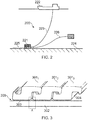
- Fig. 2 illustrates a riser assembly 200 suitable for transporting production fluid such as oil and/or gas and/or water from a sub-sea location 221 to a floating facility 222.
- the sub-sea location 221 includes a sub-sea flow line.
- the flexible flow line 225 comprises a flexible pipe, wholly or in part, resting on the sea floor 224 or buried below the sea floor and used in a static application.
- the floating facility may be provided by a platform and/or buoy or, as illustrated in Fig. 2 , a ship.
- the riser assembly 200 is provided as a flexible riser, that is to say a flexible pipe 223 connecting the ship to the sea floor installation.
- the flexible pipe may be in segments of flexible pipe body with connecting end fittings.
- Embodiments of the present invention may be used with any type of riser, such as a freely suspended (free, catenary riser), a riser restrained to some extent (buoys, chains), totally restrained riser or enclosed in a tube (I or J tubes).
- a freely suspended riser such as a freely suspended (free, catenary riser), a riser restrained to some extent (buoys, chains), totally restrained riser or enclosed in a tube (I or J tubes).
- Fig. 2 also illustrates how portions of flexible pipe can be utilised as a flow line 225 or jumper 226.
- Fig. 3 illustrates a portion of a known flexible pipe body including windings 301 1-3 of a pressure armour layer and a radially inner polymer fluid retaining layer 302.
- Fig. 4 shows an enlarged view of section A of Fig. 3 .
- an inner surface 303 of the pressure armour layer is formed from one edge of the tape profile by the repeated, adjacent windings.
- a single tape may be wound as a repeated winding (as shown in Fig. 3 ), or several tapes, possibly of different profiles, may be successively wound, with one edge of each tape profile forming the inner surface of the armour layer. Either way, a base contact surface of each profile forms an inner surface 303 of the armour layer.
- polymer barrier layer 302 and/or intermediate polymer sacrificial layer may creep into these triangles of space. This is because the high internal pressure from fluids conveyed through the pipe force the radially inner layers towards the pressure armour layer and into the spaces between the windings. This causes localised regions where part of the polymer layer is in contact with the base of the pressure armour layer and part of the polymer that is unsupported and forced into the gap between windings. In this localised region where the windings come together, the abrupt change in support to the layers underlying the pressure armour layer causes high shear and strain to the material of those underlying layers. This may result in cracking or micro-crazing.
- the layers underlying the pressure armour layer are often polymer layers, for example PVDF (polyvinylidene fluoride) although it will be appreciated that many materials may be suitable, e.g. polymers, metals, or composites.
- a suitable material may be chosen by the pipe designer to match the conditions of use of the pipe. However, most materials will have a certain maximum allowable strain above which the risk of damage to the material is much greater. As such, the presence of the above-described gaps between windings of a pressure armour layer can lead to potential damage and potential failure in the underlying layers.
- an area of polymer is under strain, the properties of that area may be changed such that it becomes weaker. In areas of strain, the polymer is more easily deformed than the surrounding material, causing an even higher level of strain in the polymer, which can result in a plastic hinge effect.
- each winding 301 1-3 of the pressure armour layer e.g. between the opposing facing surfaces of winding 301 1 and 3012.
- This gap may typically be between around 0 and 3 mm, for example, in a pressure armour layer.
- this gap allows the windings to move together or further apart to accommodate bending or movement of the pipe.
- Fig. 5 illustrates a portion of a flexible pipe body including an elongate tape element.
- the flexible pipe body includes windings 501 1-3 of a pressure armour layer, a radially inner fluid retaining layer 502 and an elongate tape element (bridging element) 508 1,2 located in a space 506 between edges 504, 505 of adjacent windings 501 and between an inner surface 503 of the pressure armour layer and a radially outer surface 514 of the fluid retaining layer 502.
- Fig. 6 shows an enlarged view of section B of Fig. 5 .
- the bridging element 508 1,2 is a continuous, relatively fine, metallic, elongate tape and is helically wound over the fluid retaining layer 502 between each successive winding of pressure armour tape (collapse resistant tape). That is, the bridging element is configured to be alternately wound with the pressure armour tape such that in cross section, windings of the bridging element alternate with windings of the pressure armour tape.
- the elastic modulus of the metallic material of the bridging element could be 170 - 210 GPa.
- the elastic modulus of the metallic material could be 190 - 210 GPa.
- the bridging element 508 1,2 may alternatively be of a relatively high elastic modulus polymeric or composite material.
- Such relatively high elastic modulus polymers could include PVDF materials with an elastic modulus greater than 400 MPa when measured at room temperature. Aptly the elastic modulus of the polymer material could be greater than 800 MPa. Aptly the elastic modulus of the polymer material could be greater than 1000 MPa. Aptly the elastic modulus of the composite material could be 20 - 50 GPa. Aptly the elastic modulus of the composite material could be 70 to 80 GPa.
- the cross section profile of the pressure armour tape 501 is substantially Z shaped with a rectangular main body and a leading edge and a trailing edge.
- the pressure armour tape, or armour tape may have other cross sectional profiles, e.g. C clip, I shaped, T shaped, X shaped or K shaped.
- the bridging element can be configured appropriately to bridge a gap between adjacent windings.
- the cross section of the elongate tape 508 is approximately rectangular with a protrusion or body portion 510 extending radially outwards into at least a portion of the gap 512 between the edges 504, 505 of adjacent windings 501. It can be seen from Fig. 5 that the elongate tape has an approximately inverted T shaped cross sectional profile.
- the bridging element 508 is arranged to extend at least partially across the gap 512 and between the inner surface 503 of the pressure armour layer and the outer surface 514 of the adjacent fluid retaining layer 502 such that the fluid retaining layer 502 is prevented from creeping into the gap 512.
- the body portion 510 of the bridging element 508 is configured to be located in the gap 512 between adjacent collapse resistant tape windings 501.
- the body portion extends radially outwards along the gap 512 to thereby help to maintain the position of the elongate tape 508 within the gap and maintaining the alternating winding configuration.
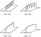
- the body portion 510 may be configured to have regular slits or slots along its length in order to allow the strip to bend more easily and form more consistently around the fluid retaining layer 502 (as shown in Figures 16a and 16b ).
- the bridging element 508 also includes two wing portions 516 1,2 , extending from an end region of the body portion 510, that span the width of the gap 512 and extend axially beyond the gap such that the radially outer surface 518 of the wing portions 516 1,2 abuts the radially inner surface 503 of the adjacent collapse resistant tape windings 501.
- a substantially flat radially inner surface 520 of the wing portions 516 1,2 abuts with the radially outer surface 514 of the fluid retaining layer 502. In this way the fluid retaining layer is prevented from creeping into the gap 512 when it is subject to internal pressure.
- the wing portions are designed to be relatively thin so as to not interfere greatly with the distance between the polymer barrier layer 502 and the pressure armour layer 501, yet strong enough to retain their position and prevent ingress of polymer into the gap 512.
- an optional transitional curved surface between respective wing portions and the body portion is configured such that the surface has a radius of curvature approximately equal to that of a curved corner between the radially inner surface 503 and the respective side walls 504, 505 of the collapse resistant tape windings 501.
- a flexible pipe body is subject to bending forces with currents, vessel movement and the like.
- the width of the gap 512 between adjacent windings of collapse resistant tape will change.
- the gap width will generally increase, while at the inner radius of the bend, the gap width will generally decrease.
- the wing span of the wing portions i.e. the full width of the two wing portions from the outermost end of a first wing to the outermost end of a second wing
- the wing portions prevent the entire bridging element from moving into the gap area 512.
- the wing span of the wing portions is about 3 times a maximum gap width between the collapse resistant tape windings.
- the transitional curved surface of the bridging element will correspond with a curved corner of a collapse resistant wire. Therefore, further stresses between adjacent tape elements are minimised.
- bridging elements are illustrated in Figs. 7 to 9 wherein a cross section of the body portion of the bridging element has an alternative shape.
- the bridging element 708 of Fig. 7 is approximately an inverted 'T-shape'.
- the bridging element 708 includes wing portions similar to those described above in relation to bridging element 508 and will therefore not be described again in detail.
- a body portion 710 of the bridging element 708 extends along the length of the gap 712, substantially along the full length of the gap in this embodiment. Wing portions extend axially from an end of the body portion 710 similarly to Fig. 6 .
- the body portion 710 is configured such that sides 721 and 722 will abut with respective side walls 704 and 705 of the adjacent collapse resistant tape windings when the gap 712 between the windings decreases.
- the radial length of the body portion 710 may be different to that shown, for example extending about 90%, or 80%, or 70%, or 60 %, or 50%, or 40%, or 30%, or 20%, or 10%, or 2%, along a radial length of the gap 712, and may be discontinuous or vary in radial length along the elongate length of the bridging element.
- the width of the body portion may also be different to the relatively thin width shown, extending about 100%, or 90%, or 80%, or 70%, or 60 %, or 50%, or 40%, or 30%, or 20%, or 10%, or 2% of the maximum gap width between adjacent windings.
- the body portion 710 of the elongate bridging element may contain a wave or non-linearity formed into it when laid on a flat surface so that when the bridging element is formed around the barrier layer 502, with the surfaces 514 and 520 in contact, the waviness in the body portion is removed due to the higher circumferential strain at the upper radial end of the body portion compared with the lower radial end of the body portion (as shown in Figs. 17a and 17b ).
- Fig. 8 shows a further bridging element / elongate tape element 808 having an approximately inverted 'T-shape'.
- the body portion 810 has an approximate U-shaped profile, with a first side portion 824, a base portion 826 and a further side portion 825. Wing portions extend from the base portion 826 of the body portion 810, similarly to Fig. 6 .
- first side portion 824 and further side portion 825 abut with respective side walls 804, 805 of adjacent collapse resistant tape windings.
- first side portion 824 and further side portion 825 extend substantially along the full length of the gap 812.
- the first side portion 824 and further side portion 825 can be considered as prongs.
- the prongs should be of a material capable of a degree of flexibility, such as steel or a relatively high elastic modulus polymeric material, such that as adjacent collapse resistant tape windings move closer together, the prongs can bend from near the base portion 826 to move closer together at an open end portion 828.
- Such relatively high modulus polymers could include some PVDF materials, composites or alloys with an elastic modulus greater than 400 MPa when measured at room temperature. Aptly the elastic modulus of the polymer material could be greater than 800 MPa. Aptly the elastic modulus of the polymer material could be greater than 1000 MPa. Aptly the elastic modulus of the composite material could be 20 - 50 GPa.
- the elastic modulus of the composite material could be 70 - 80 GPa.
- the elastic modulus of a metallic material of the prongs could be 170 - 210 GPa.
- the elastic modulus of the metallic material could be 190 - 210 GPa.
- Fig. 9 shows a further bridging element / elongate tape element 908 having an approximately inverted 'T-shape'.
- the bridging element 908 has a similar cross sectional profile to that shown in Fig. 7 .
- the body portion 910 is wider than that of the embodiment of Fig. 7 , being approximately the width of the maximum gap width 912.
- the bridging element is at least partially compressible, yet with sufficient strength to prevent substantial ingress of a polymer barrier layer into the gap 912.
- the bridging element may be non-metal, a polymer, an elastomer, a rubber, a foam, or any other resilient material suitable to be temporarily compressed when adjacent windings of collapse resistant tape move closer together, or be constructed from an internal skeleton structure such as 710 or 810 while being encapsulated by, or encapsulating a suitably compressible resilient material as described above.
- Suitably compressible materials could have an elastic modulus considerably less than 400 MPa, for instance 150 MPa, for instance 50 MPa, for instance 10 MPa, for instance 1 MPa, for instance 0.08 MPa, and may be a rubber or foamed material.
- the body portion 910 has a width of up to the maximum gap width, if the gap 912 were to decrease in width (such as during bending of a pipe), the compressibility of the material used for the bridging element allows the bridging element to expand and contract in line with the changing gap width.
- the radial length of the body portion may be different to that shown, for example extending about 90%, or 80%, or 70%, or 60 %, or 50%, or 40%, or 30%, or 20%, or 10%, or 2%, along a radial length of the gap 912, and may be discontinuous or vary in radial length along the elongate length of the bridging element.
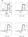
- Figs. 10a and 10b show a yet further a bridging element/ elongate tape element 1008 having an approximately 'S-shape'.
- Fig. 10a shows the positioning of the bridging element 1008 when the collapse resistant tape windings 1001 1,2 are arranged such that the width of the gap 1012 is at its maximum.
- the bridging element 1008 has a body portion 1010 that extends along the gap 1012 abutting with a side wall 1005 of the adjacent collapse resistant tape winding 10012.
- the body portion continues to form a hooked end region 1015, which is substantially hook shaped so as to accommodate a trailing edge of the adjacent collapse resistant tape winding 10012.
- the hooked end region 1015 thereby acts to help the bridging element 1008 remain in place with the body portion 1010 abutting the side wall 1005.
- the bridging element 1008 further includes a wing portion 1016 that extends from an end region of the body portion to thereby span the maximum width of the gap 1012.
- the wing portion 1016 further extends between an inner surface 1003 of the collapse resistant tape winding 1001 1 and an outer surface of a fluid retaining layer 1002.
- the wing portion 1016 is larger than the maximum gap width, and aptly 125%, or 150%, or 200%, or 300% of the maximum gap width.
- the body portion is effectively connected or attached to one adjacent winding of the pressure armour layer so that it is unable to stray from that position and will remain always adjacent to that side winding whether the gap width is large or small.
- the wing portion is wide enough such that even at the maximum gap width, the gap is bridged by the wing portion.
- Physical attachment means such as adhesive may also be used to connect or help connect in lieu of or in addition to the hooked end region of the bridging element to the adjacent pressure armour winding.
- Fig. 10b shows the positioning of the bridging element 1008 when the collapse resistant tape windings 1001 1,2 are arranged such that the width of the gap 1012 is at its minimum.
- the body portion 1010 abuts with side walls of each adjacent collapse resistant tape winding.
- the wing portion is positioned similarly to in Fig. 10a , but a larger portion lies between the inner surface of the collapse resistant tape winding and the outer surface of the fluid retaining layer.
- the elongate tape element 1016 has a substantially uniform thickness across the cross-sectional profile. That is, the wire/sheet forming body portion 1010 and the wing portion 1016 is of uniform thickness.
- Figs. 11a and 11b show a similar bridging element in which the thickness across the cross-sectional profile of the bridging element is not uniform.
- a body portion 1110 of a bridging element 1108 is thicker than a wing portion 1116.
- the body portion and wing portion are shaped to accommodate the curvature of the adjacent pressure armour layer windings (as can be seen in Figs. 10c and 11c ).
- the wing portion will always extend across the full gap width to prevent any point of ingress for the polymer barrier layer into the gap between windings.
- Flexible pipe body may be formed with any of the above-described bridging elements.
- a fluid retaining layer is provided.
- This may be a polymer layer or formed from metals or composites, for example. If a polymer is used, the polymer may be extruded using techniques known in the art to form a tubular polymer layer.
- an elongate tape element (as per any of the above) and a collapse resistant tape (e.g. pressure armour wires) are helically wound over the fluid retaining layer to form alternate windings.
- the elongate tape element is located at least partially within a gap between adjacent collapse resistant tape windings and configured to span the gap so as to abut with a radially inner surface of each adjacent collapse resistant tape winding.
- the wing portions have been described above with a substantially uniform thickness, the wing portions may be tapered away from the body portion such that while the radially inner surface of the bridging element remains substantially flat to abut with the fluid retaining layer, the radially outer surface may taper or be shaped to correspond with an adjacent collapse resistant tape winding.
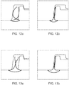
- a spring or clip of material to be configured to locate in the gap between, and / or around the collapse resistant tape wraps, as shown in Figs. 12a, 12b , 12c , 13a, 13b , 13c .
- Such spring or clips would function in a similar manner to the bridging element shown in Fig. 8 .
- FIGs. 14, 15a and 15b A further alternative bridging element is shown in Figs. 14, 15a and 15b . These are similar to those shown in Fig. 5 , with slight changes to the design of the body portion.
- the bridging element may comprise metal, aluminium alloy, non-metal, a polymer, an elastomer, a rubber, a foam or a combination of these, for example a coated metallic sheet, the coating to provide corrosion protection and or wear resistance and or low coefficient of friction (for example 1, 0.5, 0.1, or 0.05).
- this body portion length may be other suitable lengths.
- Figures 16 and 17 show bridging elements which are shaped in order to increase the ease with which they may be formed around the circumference of a cylindrical structure.
- Figure 16a shows a nominally T profile bridging element which incorporates a body portion into which a plurality of up-stand sections have been created either by removal of material from the body portion or by cleavage of the body portion (the spaces between these sections are herein after known as "gaps"), providing gaps between body up-stand sections along the bridging element's length, the gaps extending at least part way down the height of the body portion.
- the dimensions of the gaps in the body portion as a result of cleaving or the removal of material may be consistent along the length of the bridging element, or may vary.
- the gaps are in the range 0 - 25mm wide. Aptly the gaps are in the range 0 - 10mm wide. Aptly the gaps are in the range 0 - 5mm wide.
- the frequency of the gaps per unit length of bridging element may also be consistent or vary, depending on the dimensions of pipe body the bridging element is to be fitted into.
- the shape of the gaps may be U shaped, or V shaped or such as an inverted key-hole, or other suitable shapes in order to limit or eliminate the risk of stress concentrations leading to fracturing of the bridging element material during bending of the bridging element.
- the gaps may be alternatively formed into the bridging element profile during manufacture of the bridging element or after manufacturing the bridging element, either before or during the forming process for inserting the bridging element into the pipe body structure.
- FIG. 16b shows the bridging element formed around a cylindrical structure (not shown) indicating how the gaps open increasingly towards their radially outermost extent on bending the bridging element.
- Figure 17a shows a bridging element which nominally comprises a T profile.
- the body portion of the element is formed with a crinkled shape along the length of the bridging element.
- the crinkle is displayed over at least 10% of the radially outer end of the body portion.
- the crinkled shape is generally of a sinusoidal form increasing in the sinusoidal wave height towards the radially outer end of the body portion.
- the crinkle in the body portion may be formed during the manufacture of the bridging element, or just prior to, or during the use of the bridging element in forming a layer in to the pipe body structure.
- the crinkle may optionally be created through the application of force from rolls either side of the body portion, effectively lengthening the body portion with respect to the wing portion of the bridging element.
- the rolls performing this permanent deformation of the body portion are conical (in order to progressively apply more thinning at the radially outermost end of the body portion and therefore direct the greatest extension of the body to that location).
- the rolls are asymmetric or convoluted in order to achieve a similar crinkle effect in the body portion.
- the radially outermost part of the body portion also exhibits the thinnest section thickness, the thickness tapering outwardly from the radially innermost point at which the deformation has been applied.
- Figure 17b shows the bridging element bent around a cylindrical structure (not shown), indicating how the crinkle straightens out as a result of the bending process, enabling a smooth, uniform curvature to be achieved without risk of buckling or undesired folding of the body portion.
- the layer formed as described above may be used in conjunction with any or all of the other flexible pipe body layers as described with reference to Fig. 1 .
- Fig. 18 illustrates how an elongate tape element 1800 can be utilised as a bridging element for bridging a gap 1805 between adjacent windings of a flexible pipe body layer.
- the pressure resistant layer illustrated in Fig. 18 is a carcass layer 1810.
- the carcass layer 1810 is a collapse resistant layer. That is to say the carcass layer, in use, helps prevent the pipe from collapsing by resisting flattening of the barrier layer which is formed over the carcass layer in a radially outer location subsequent to formation of the carcass layer 1810.
- a fluid communicating bore 1820 is provided by a radially inner surface of the barrier layer formed outside the carcass layer. A radially innermost surface of the carcass layer nevertheless forms a non fluid tight bore against which production fluids flow as they are transported along the length of the flexible pipe.
- the elongate tape element 1810 is located between adjacent primary carcass tape windings which would otherwise present a series of gaps along the length of the carcass layer which might create vortex shedding opportunities. By locating an elongate tape element in these gaps as herein described FLIP caused by such vortex shedding can entirely or at least partially be avoided.
- the elongate tape element includes a body portion 1830 that is at least partially locatable between adjacent windings of the collapse resistant layer. The body portion 1830 is at least partially locatable in the gap 1805 between edges of adjacent carcass windings that each have a curved surface region.
- the central body portion is a folded region of a tape and a first wing portion 1840 and a further wing portion 1850 extend in an axial direction, when duly located between primary carcass layer windings, in an opposed manner away from the central body portion.
- the first wing portion ends in a first long edge 1860 of the elongate tape element whilst the further wing portion 1850 has a wing end formed at a remaining long edge 1870 of the elongate tape element.
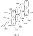
- Fig. 19 helps illustrate a method for manufacturing the elongate tape 1800 illustrated in Fig. 18 .
- a sheet 1900 which is a thin narrow strip that is flat and which has a common cross section is wound off a reel of such tape. It will be understood that such reels are often referred to by those skilled in the art as a pancake.
- the sheet 1900 is a metal sheet.
- the tape 1900 is a stainless steel tape.
- Other materials could of course be optionally utilised as a sheet to produce an elongate tape element.
- the sheet can be a composite material or an aluminium alloy or the like.
- the sheet 1900 is provided to a first pair 1910 of a plurality (four shown in Fig. 19 ) of pairs of opposed rollers.
- the first pair 1910 includes a first upper roller 1912 and a lower roller 1914.
- the rollers are driven about respective axes which helps draw the tape 1900 presented at a nip point of the first pair of rollers along a roll forming line associated with the pairs of rollers.
- a second pair of opposed roll forming rollers includes an upper roller 1922 and lower roller 1924.
- a third pair 1930 of opposed rollers includes an upper roller 1932 and a lower roller 1934.
- a fourth pair 1940 of opposed rollers includes an upper roller 1942 and a lower opposed roller 1944.
- Each roller in each pair has a respective profile formed in its outer surface 1950 so that as that the strip is drawn through the nip point of the various pairs of rollers a cross sectional profile is sequentially formed in the tape turning the tape from a substantially flat sheet to an elongate tape element having a body portion and at least one wing portion but retaining a substantially uniform thickness across a resulting cross sectional profile.
- four pairs of roller have been described one, two, three, four, five or more pairs could aptly be used.
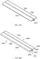
- Fig. 20A to Fig. 20D illustrate the cross sectional profiles formed by the pairs of opposed rollers illustrated in Fig. 19 as an illustrative way in which a flat sheet can be formed at a relatively low cost and without over complex manufacturing steps being needed into an elongate tape element that can be wound between adjacent windings of a carcass layer to help avoid FLIP.
- This method of forming is cheaper and less prone to error than other forming techniques such as extrusion or moulding.
- the starting point is a sheet 1900 that has a substantially uniform thickness extending from a first long edge 1860 to a further long edge 1870.
- the long edges, 1860 1870 are substantially parallel and arranged in a spaced apart relationship.
- a leading short edge 2010 of the sheet 1900 is an edge that extends between the first and further long edge. This leading edge 2010 is the edge which is urged between the nip point of the rollers of the first pair of rollers.
- the length of the tape is determined by the storage capacity for storing the flat strip prior to the forming process and/or carcass layer forming process.
- Starting with a flat strip means new flat strip can be welded to a end of a previous strip easily to help provide a continuous manufacturing process.
- Fig. 20B illustrates the cross sectional profile of the strip subsequent to being rolled between the opposed rollers of the first pair of rollers.
- the strip which starts as a sheet having a flat cross-sectional profile, and which is thus relatively cheap to purchase and transport is formed into a cross section which has a inset region 2020 and a first fold line 2030 leading from the inset region 2020 via a generally flat intermediate region 2040 to the first long edge 1860.
- a further fold line 2050 is formed by the first pair of rollers in the elongate tape and extends via a generally flat intermediate region 2060 to the remaining further long edge 1870.
- the folded sheet exiting each pair of rollers until a final pair of rollers provides a precursor for the next pair of rollers.
- Each fold line can be a sharp fold or a gradual fold line.
- Fig. 20C illustrates the cross sectional profile of the tape as it emerges from the second pair 1920 of opposed rollers.
- a cross sectional profile formed by modifying the tape element shown in Fig. 20B has had the central inset region 2020 closed somewhat and the generally flat "wings" 2040, 2060 which include the generally flat intermediate regions folded downwards towards a base 2070 of the tape.
- Fig. 20D illustrates a cross sectional profile of the elongate tape element in a final format as generally provided by passing the tape element having a cross section shown in Fig. 20C through the third pair 1930 of opposed rollers.
- a central body portion 1805 of the cross sectional profile of the tape is made by urging the inset region 2020 further together. This nipping action creates a body portion having a first side portion 2075 which extends from a base 2080 to a further side portion 2085.
- an optional dipped wing tip 2087 is formed in the first wing by inclining downwardly a narrow section of the tape leading to the first long edge 1860.
- an optional wing tip region 2090 is formed along a narrow edge of the strip terminating in the remaining long edge 1870 of the tape.
- the body portion 1830 thus has a substantially U-shaped profile.
- the body portion extends away from the wings substantially at right angles.
- the body portion may be wave-like, arcuate or set at an acute or obtuse angle with respect to a wing.
- the side portions of the body portion can be squeezed tightly together to close as much a possible the inset region 2020 which extends longitudinally along the length of the tape.
- the side portions can remain more opened away from the base portion 2080 so as to provide an inset region 2020 having a wider open mouth like area.
- this wider open area can likewise be enhanced by folding the wings about respective fold lines 2030, 2050 having a greater radius of curvature ie. the fold line is not sharp.
- the provision of a central inset region which extends longitudinally along the length of the tape, and which can have a selectable width responsive to how closed the channel is in the body portion can have desirable fluid dynamic effects on the flow of production fluids flowing along the inner surface of the carcass layer formed by the wound carcass windings and the bridging element tape. This can help further reduce vortex shedding/FLIP effects.
- the fourth pair of rollers illustrated in Fig. 19 can thus be utilised to confirm the profile of the tape emerging from the third pair of rollers and duly locate and/or direct the thus formed tape in a direction towards either a storage facility where rolls of the tape can be rolled and subsequently stored or directly to a location on a carcass forming station where carcass layer windings having an interlocking structure are duly located and a carcass layer manufactured.
- Fig. 21 helps illustrate a cross-sectional profile of primary windings of a carcass layer and how the elongate tape formed via the steps shown in Figs. 19 and 20 can be located into gaps between adjacent carcass layer windings.
- a preceding winding 2100 of a carcass layer winding is wound against an underlying substantially cylindrical outer surface of a mandrel (shown more clearly in Fig. 22 ) and then the elongate tape element 1800 which provides a bridging element is located at an end region 2110 of the preceding carcass layer winding.
- at least a part 2120 of the carcass layer winding is a curved surface.
- the body portion 1830 of the bridging element extends like a nose into the gap 1805.
- the base 2080 of the body portion is spaced apart from the inset region 2020 which provides a substantially V-shaped inset in a radially inner surface formed by a radially inner surface of each wing 2040, 2060.
- a succeeding carcass layer winding 2140 is then wound around an underlying cylindrical mandrel layer. This succeeding winding also includes a curved surface 2150 which opposes the curved surface 2120 of the preceding winding. In use the space between successive carcass layer windings increases and decreases as the flexible pipe body flexes. As illustrated in Fig.
- the wing tips are bent slightly towards respective carcass layer windings and in this way tips of the wings remain at all time in contact with carcass layer windings. This helps avoid production fluids in use from flowing under the elongate tape 1800.
- the tips which are dipped ride along a surface of the carcass windings and help minimise the contact area between the elongate tape 1800 and respective carcass layer windings so as to maximise flexibility in the flexible pipe body.
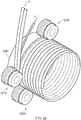
- Fig. 22 helps illustrate how primary carcass layer tape which has a substantially S or Z cross-sectional profile can be wound onto an outer cylindrical surface 2200 of a mandrel at a carcass forming station. It is to be noted that part of the cylindrical outer surface of the mandrel is illustrated in Fig. 22 .
- a carcass layer tape having a pre-formed cross section is provided to the carcass layer forming station in a direction illustrated by arrow X and is guided onto the outer surface 2200 of the mandrel via a first support roller 2210.
- This roller and successive rollers 2220, 2230 circumferentially arranged around the mandrel have outer surfaces which are profiled to include guides for both the primary carcass layer tape and the elongate tape 1800 which is introduced at the winding station in a direction illustrated by arrow Y.
- successive windings of the carcass layer of the primary carcass layer tape interlock to form an interlocked structure which does not require the support of the mandrel.
- An inner surface of the carcass layer so produced is provided by a radially inner surface of primary carcass layer windings and radially inner surface regions of the elongate tape 1800.
- the carcass layer itself presents an essentially smooth or almost smooth inner bore along which production fluids can flow in use. Because the inner surface is substantially smooth vortex shedding is minimised during transportation of production fluids and thus FLIP can entirely or at least partially be avoided.
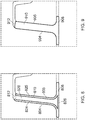
- Fig. 23 helps illustrate an alternative cross-sectional profile of an elongate tape element which can be used as a bridging element 2300.
- a body portion 2330 includes a bent region 2332 and a first substantially linear intermediate region 2334 which extends to a respective long edge 1860 of the tape.
- a wing tip region 2336 is downturned slightly in a dipped fashion.
- a central inset region 2340 is provided which is substantially V-shaped. This is located where a first side portion 2344 of the body portion 2330 is nipped against a further side wall 2346 of the body portion 2330. The side walls of the body portion are thus in an abutting relationship.
- the further side wall 2346 extends through a folded region 2348 via a further substantially linear intermediate region 2354 to the remaining long edge 1870 of the tape.
- the cross-sectional profile thus only includes dipped wing tips, which extend from the respective edges of the tape, respective intermediate regions of the tape and a central folded region.
- Fig. 24 illustrates an alternative cross-sectional profile for a bridging element 2400 formed via a similar but slightly different manufacturing technique in which wing tip regions 2436 are not dipped downwardly but rather have a substantially planar radially outer surface 2444, 2446 but with tapered wing tips. That is to say tips which lead to the respective long edges 1860, 1870 of the strip are tapered to form a narrowing point towards long edges of the bridging element. Aptly the taper is provided by compressing the material of the elongate tape at the long edges.
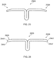
- Fig. 25 illustrates an alternative cross-sectional profile for a bridging element 2500 in which wing tips are downturned. That is to say are turned inwardly at a side of the cross-sectional profile where the body portion is located Additionally each of the wing tips 2536 2538 are tapered by shaving or compression.
- Fig. 26 illustrates a further alternative cross-sectional profile for a bridging element 2600 in which wing tips 2636, 2638 are produced by creating respective long edges of the tape via a cutting action.
- the cutting action used to create the flat strip which is subsequently folded to create the cross-sectional profile shown in Fig. 26 has an effect of consolidating material at one surface of the flat tape so as to form a curved region 2640, 2642 and this helps provide a pointed region 2650, 2652. This helps minimise the material in contact with adjacent primary carcass layer windings in use and helps the bridging element ride smoothly along surfaces of adjacent carcass windings as the flexible pipe body flexes in use.
- the wing tip regions can be created in a very straightforward manner without complex manufacturing steps by cutting the strip using opposed scissor-like cutting tools.
- Fig. 27 illustrates adjacent windings of a carcass layer with an alternative bridging element 2700 which has a body portion slightly leant towards a particular long edge/wing of the bridging element. This attitude can be created during the manufacturing step for providing the bridging element.
- the bridging portion 2730 forms an obtuse angle with a line or plane associated with the first wing terminating in the first edge 1860 of the tape whilst the bridging portion 2730 forms an acute angle with a line/plane associated with the further wing which terminates in the further long end 1870.
- This non-orthogonal orientation helps duly locate the body portion in the particular shape of gap between adjacent curved surfaces of primary carcass layer windings.
- bridging elements that have dipped and/or tapered ends to the wing tips helps streamline the way in which the tape lies over primary carcass layer windings which helps provide smooth fluid flow along the flexible pipe.
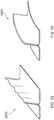
- Fig. 28 illustrates a bridging element.
- the body portion of the bridging element 2800 is formed with a crinkled shape along the length of the bridging element. Aptly the crinkled shape is displayed over at least 10 percent of the radially outer end of the body portion.
- the crinkled shape is generally of a sinusoidal form increasing in sinusoidal wave height towards the radially outer end of the body portion.
- the crinkle in the body portion may be formed during the manufacture of the bridging element or just prior to, or during the use of the bridging element in forming a layer in a pipe body structure.
- the crinkle is optionally be created through the application of force from rolls on either side of the body portion.
- the rolls performing the permanent deformation of the body portion are conical (in order to progressively apply more thinning at the radially outermost end of the body portion and therefore direct a greatest extension of the body to that location).
- Aptly the rolls are asymmetric or convoluted in order to achieve a similar crinkle effect in the body portion.
- the radially outermost part of the body portion also exhibits the thinnest section thickness.
- the thickness tapering outwardly from the radially innermost point at which the deformation has been applied. Nevertheless the elongate tape element retains a substantially uniform thickness across the cross-sectional profile.
- the effect on thickness is shown in an exacerbated form in the figures to help show the effect. In practice the change in thickness would be almost imperceptible.
- Fig. 29 illustrates the bridging element shown in Fig. 28 bent around a cylindrical structure (not shown), indicating how the crinkle straightens out as a result of the bending process, enabling a smooth, uniform curvature to be achieved without risk of buckling or undesired folding of the body portion.
- the body portion and wing portion or portions are arranged such that even at a maximum gap width, and even with the body portion located in its most extreme position abutting a left side wall or right side wall, the gap between windings will still be covered by the wing portion(s) and optionally also the body portion.
- collapse resistant layer or “collapse resistant wire” or similar terms have been used to broadly identify one layer or wire of a pipe body provided to resist collapse of the pipe body or resist pressure applied to the pipe body (external or internal pressure).
- collapse resistant layers may be a pressure armour layer or a carcass layer, for example.
Landscapes
- Engineering & Computer Science (AREA)
- General Engineering & Computer Science (AREA)
- Mechanical Engineering (AREA)
- Rigid Pipes And Flexible Pipes (AREA)
- Shaping Of Tube Ends By Bending Or Straightening (AREA)
- Tires In General (AREA)
Claims (17)
- Flexibler Rohrkörper (100) zum Transportieren von Produktionsfluid, umfassend eine Fluidrückhalteschicht (102), wobei der flexible Rohrkörper (100) mit einem länglichen Bandelement (1800) gebildet ist, um eine Lücke (1805) zwischen Windungen einer Schicht des flexiblen Rohrkörpers, die ineinandergreifen, zu überbrücken, wobei das Bandelement (1800) ein Querschnittsprofil aufweist, umfassend:einen Körperabschnitt (1830), der zumindest teilweise in einer Lücke (1805) zwischen benachbarten Windungen, die ineinandergreifen, einer Schicht eines flexiblen Rohres platzierbar ist;einen ersten Flügelabschnitt (1840), der sich von dem Körperabschnitt (1830) zu einem ersten Flügelende (1860) erstreckt; undeinen weiteren Flügelabschnitt (1850), der sich von dem Körperabschnitt (1830) zu einem weiteren Flügelende (1870) erstreckt;dadurch gekennzeichnet, dassdas längliche Bandelement (1800) eine im Wesentlichen einheitliche Dicke quer durch das Querschnittsprofil aufweist.
- Flexibler Rohrkörper (100) nach Anspruch 1, ferner umfassend eine Karkassenschicht (1810).
- Flexibler Rohrkörper (100) nach einem vorhergehenden Anspruch, wobei das längliche Bandelement (1800) ferner Folgendes umfasst:
jeder Flügelabschnitt (1840, 1850) umfasst eine im Wesentlichen flache innere Oberflächenregion. - Flexibler Rohrkörper (100) nach einem vorhergehenden Anspruch, wobei das längliche Bandelement (1800) ferner Folgendes umfasst:
das längliche Bandelement (1800) ist spiralförmig zwischen aufeinanderfolgenden Windungen windbar, die die benachbarten Windungen einer Schicht eines flexiblen Rohres bereitstellen. - Flexibler Rohrkörper (100) nach einem vorhergehenden Anspruch, wobei das längliche Bandelement (1800) ferner Folgendes umfasst:
der erste und weitere Flügelabschnitte (1840, 1850) erstrecken sich jeweils von einer Endregion des Körperabschnittes (1830). - Flexibler Rohrkörper (100) nach einem vorhergehenden Anspruch, wobei das längliche Bandelement (1800) ferner Folgendes umfasst:
eine äußere Oberflächenregion von jedem von dem ersten und weiteren Flügelabschnitten (1840, 1850) ist platzierbar, um an eine innere Oberflächenregion der benachbarten Windungen anzustoßen. - Flexibler Rohrkörper (100) nach einem vorhergehenden Anspruch, wobei das längliche Bandelement (1800) ferner Folgendes umfasst:
das erste Flügelende (1860) umfasst eine erste lange Kante des Bandelements und das weitere Flügelende (1870) umfasst eine weitere lange Kante des Bandelements. - Flexibler Rohrkörper (100) nach einem vorhergehenden Anspruch, wobei das Querschnittsprofil des länglichen Bandelements (1800) lediglich Folgendes umfasst:den ersten Flügelabschnitt (1840), der sich von dem ersten Flügelende (1860) an einer langen Kante des Bandelements zu dem Körperabschnitt (1830) über einen ersten im Wesentlichen linearen Zwischenabschnitt erstreckt;den Körperabschnitt (1830), der einen gefalteten mittleren Abschnitt des Profils umfasst; undden weiteren Flügelabschnitt (1850), der sich von dem weiteren Flügelende (1870) an einer weiteren langen Kante des Bandelements zu dem Körperabschnitt (1830) über einen weiteren, im Wesentlichen linearen Zwischenabschnitt erstreckt.
- Flexibler Rohrkörper (100) nach Anspruch 8, wobei das längliche Bandelement (1800) ferner Folgendes umfasst:der erste Flügelabschnitt (1840) umfasst ferner eine erste Flügelspitzenregion zwischen dem ersten Flügelende (1860) und dem ersten Zwischenabschnitt; undder weitere Flügelabschnitt (1850) umfasst ferner eine weitere Flügelspitzenregion zwischen dem weiteren Flügelende (1870) und dem weiteren Zwischenabschnitt.
- Flexibler Rohrkörper (100) nach Anspruch 9, wobei das längliche Bandelement (1800) ferner Folgendes umfasst:
jede Flügelspitzenregion ist über eine jeweilige Faltlinie in eine eingetauchte Position nach unten gefaltet, um die Flügelspitzenregion in Bezug auf eine benachbarte Zwischenregion eines jeweiligen Flügelabschnittes zu neigen. - Flexibler Rohrkörper (100) nach einem vorhergehenden Anspruch, wobei das längliche Bandelement (1800) zumindest teilweise innerhalb der Lücke (1805) platzierbar ist, um die Lücke (1805) zu umspannen, um an eine radial innere Oberfläche jeder benachbarten Windung anzustoßen.
- Flexibler Rohrkörper (100) nach einem vorhergehenden Anspruch, wobei das längliche Bandelement (1800) ferner Folgendes umfasst:
der Körperabschnitt (1830) und die Flügelabschnitte (1840, 1850) sind so angeordnet, dass sogar bei einer maximalen Lückenbreite, und sogar, wenn sich der Körperabschnitt (1830) in seiner extremsten Position befindet, die an eine linke Seitenwand oder eine rechte Seitenwand anstößt, die Lücke (1805) zwischen Windungen immer noch durch die Flügelabschnitte (1840, 1850) und den Körperabschnitt (1830) bedeckt wird. - Flexibler Rohrkörper (100) nach einem vorhergehenden Anspruch, wobei das längliche Bandelement (1800) ferner Folgendes umfasst:
eine Flügelspanne der Flügelabschnitte (1840, 1850), die größer als eine maximal mögliche Breite der Lücke (1805) ist. - Flexibler Rohrkörper (100) nach einem vorhergehenden Anspruch, wobei der Körperabschnitt (1830) des länglichen Bandelements (1800) zumindest teilweise in einer Lücke (1805) zwischen Kanten benachbarter Windungen, die jeweils eine gebogene Oberfläche aufweisen, platzierbar ist.
- Flexibler Rohrkörper (100) nach Anspruch 1, umfassend eine deformationsfeste Schicht, die das Band aufweist, das alternativ auf spiralförmige Weise mit einem deformationsfesten Band gewunden ist.
- Flexibles Rohr, umfassend den flexiblen Rohrkörper (100) nach einem vorhergehenden Anspruch, zusammen mit einer Endpassung, die sich an zumindest einem Ende des flexiblen Rohrkörpers (100) befindet.
- Verwendung eines länglichen Bandelements (1800), um eine Lücke (1805) zwischen Windungen einer Schicht eines flexiblen Rohrkörpers, die ineinandergreifen, zu überbrücken, wobei das Bandelement (1800) wie in einem der Ansprüche 1 bis 15 beschrieben ist.
Applications Claiming Priority (3)
| Application Number | Priority Date | Filing Date | Title |
|---|---|---|---|
| GBGB1306665.9A GB201306665D0 (en) | 2013-04-12 | 2013-04-12 | Elongate tape element and method |
| EP14717826.3A EP2983843A1 (de) | 2013-04-12 | 2014-04-11 | Längliches bandelement und verfahren |
| PCT/GB2014/051134 WO2014167346A1 (en) | 2013-04-12 | 2014-04-11 | Elongate tape element and method |
Related Parent Applications (1)
| Application Number | Title | Priority Date | Filing Date |
|---|---|---|---|
| EP14717826.3A Division EP2983843A1 (de) | 2013-04-12 | 2014-04-11 | Längliches bandelement und verfahren |
Publications (2)
| Publication Number | Publication Date |
|---|---|
| EP3403739A1 EP3403739A1 (de) | 2018-11-21 |
| EP3403739B1 true EP3403739B1 (de) | 2020-02-26 |
Family
ID=48537156
Family Applications (3)
| Application Number | Title | Priority Date | Filing Date |
|---|---|---|---|
| EP18177456.3A Active EP3403739B1 (de) | 2013-04-12 | 2014-04-11 | Flexibles rohr |
| EP14717828.9A Active EP2994252B1 (de) | 2013-04-12 | 2014-04-11 | Längliches bandelement für biegsame rohrleitung |
| EP14717826.3A Withdrawn EP2983843A1 (de) | 2013-04-12 | 2014-04-11 | Längliches bandelement und verfahren |
Family Applications After (2)
| Application Number | Title | Priority Date | Filing Date |
|---|---|---|---|
| EP14717828.9A Active EP2994252B1 (de) | 2013-04-12 | 2014-04-11 | Längliches bandelement für biegsame rohrleitung |
| EP14717826.3A Withdrawn EP2983843A1 (de) | 2013-04-12 | 2014-04-11 | Längliches bandelement und verfahren |
Country Status (9)
| Country | Link |
|---|---|
| US (3) | US10683951B2 (de) |
| EP (3) | EP3403739B1 (de) |
| CN (3) | CN105473248B (de) |
| AU (2) | AU2014252827A1 (de) |
| BR (2) | BR112015025999B1 (de) |
| DK (2) | DK2994252T3 (de) |
| GB (1) | GB201306665D0 (de) |
| MY (3) | MY174876A (de) |
| WO (2) | WO2014167349A2 (de) |
Families Citing this family (22)
| Publication number | Priority date | Publication date | Assignee | Title |
|---|---|---|---|---|
| GB201306665D0 (en) | 2013-04-12 | 2013-05-29 | Wellstream Int Ltd | Elongate tape element and method |
| FR3017438B1 (fr) | 2014-02-11 | 2016-10-14 | Technip France | Conduite flexible de transport de fluide et procede associe |
| FR3017439B1 (fr) | 2014-02-13 | 2016-10-14 | Technip France | Conduite flexible de transport de fluide munie d'un insert en forme de s etendu et procede de fabrication associe |
| GB201611342D0 (en) * | 2016-06-30 | 2016-08-17 | Ge Oil & Gas Uk Ltd | Sacrificial shielding |
| GB201615346D0 (en) | 2016-09-09 | 2016-10-26 | Ge Oil & Gas Uk Ltd | Interlocked layer and method of manufacture |
| GB201616706D0 (en) * | 2016-09-30 | 2016-11-16 | Ge Oil & Gas Uk Limited | Thermoplastic composite |
| GB201620745D0 (en) * | 2016-12-06 | 2017-01-18 | Ge Oil & Gas Uk Ltd | immobilised insert |
| EP3596379B1 (de) * | 2017-03-16 | 2024-10-09 | Baker Hughes Energy Technology UK Limited | Herstellungsverfahren für kathodischen schutz |
| FR3065273B1 (fr) * | 2017-04-12 | 2019-06-21 | Technip France | Procede de fixation d'un element d'ancrage sur un element d'armure d'une conduite flexible, conduite et methode de montage associees |
| FR3068104B1 (fr) * | 2017-06-22 | 2019-07-19 | Technip France | Installation pour la fabrication d'une structure de renfort d'une conduite flexible, procede associe et systeme comprenant ladite installation |
| CN108119708B (zh) * | 2018-01-17 | 2023-12-08 | 哈尔滨工程大学 | 一种非粘结柔性立管工型截面互锁抗压铠装层 |
| CN108825929A (zh) * | 2018-09-07 | 2018-11-16 | 广州远和船海研究院有限公司 | 柔性管复合抗压铠装层 |
| CN108825894A (zh) * | 2018-09-07 | 2018-11-16 | 广州远和船海研究院有限公司 | 一种海洋用柔性管的骨架层和复合柔性管 |
| IT201800009085A1 (it) * | 2018-10-02 | 2020-04-02 | Manuli Hydraulics Italia Srl | Tubo idraulico flessibile |
| US11718459B1 (en) * | 2019-09-03 | 2023-08-08 | TredWear LLC | Flat interlocking wrap for complex shapes |
| CN110500451B (zh) * | 2019-09-17 | 2024-04-05 | 萍乡市大地新材料科技有限公司 | 扣合式热态缠绕实心波纹管及其型材及其制造方法 |
| CN112248307B (zh) * | 2020-09-14 | 2021-11-19 | 大连理工大学 | 一种结构可调的折叠结构复材成型模具 |
| US11629801B2 (en) * | 2021-02-26 | 2023-04-18 | Polyflow Llc | Unbonded reinforced plastic pipe |
| CN114165654B (zh) * | 2021-12-09 | 2022-08-09 | 中国石油大学(北京) | 海洋非粘结柔性软管的端部接头配件、立管结构及其应用 |
| CN114321522B (zh) * | 2022-01-05 | 2022-11-22 | 中国石油大学(北京) | 一种用于动态软管的异型材、骨架层及含该骨架层的产品 |
| GB2621597A (en) * | 2022-08-16 | 2024-02-21 | Baker Hughes Energy Technology UK Ltd | Smoothing insert |
| CN115394483A (zh) * | 2022-09-01 | 2022-11-25 | 安徽尚柯电气有限公司 | 联锁铠装式电伴热带及其制造方法 |
Family Cites Families (53)
| Publication number | Priority date | Publication date | Assignee | Title |
|---|---|---|---|---|
| DE349051C (de) | 1922-02-23 | Jacob Geb | Metallschlauch | |
| US846996A (en) * | 1906-01-24 | 1907-03-12 | Edwin T Greenfield | Tubing. |
| GB468476A (en) * | 1936-05-25 | 1937-07-06 | Carl Minter Yoder | Improvements in or relating to machines for shaping or curving metal |
| GB1081339A (en) | 1965-04-28 | 1967-08-31 | Angus George Co Ltd | Improvements in flexible ducting |
| US3580289A (en) | 1967-01-09 | 1971-05-25 | Polymer Corp | Flexible hose construction |
| US4062380A (en) | 1976-10-28 | 1977-12-13 | Dayco Corporation | Hose construction |
| US4304266A (en) | 1980-03-24 | 1981-12-08 | Automation Industries, Inc. | Smooth bore flexible hose |
| FR2555920B1 (fr) | 1983-12-06 | 1987-05-07 | Coflexip | Dispositif pour realiser en continu une structure tubulaire spiralee en feuillard agrafe |
| DE3409734A1 (de) | 1984-03-20 | 1985-09-26 | The Furukawa Electric Co., Ltd., Tokio/Tokyo | Biegsame rohrleitung fuer den transport fliessender medien |
| JPH0412298Y2 (de) * | 1986-12-26 | 1992-03-25 | ||
| US5275209A (en) | 1988-05-09 | 1994-01-04 | Institut Francais Du Petrole | Hose including an aluminum alloy |
| NL8801702A (nl) * | 1988-07-05 | 1990-02-01 | Redeco Ag | Flexibele, in een richting buigzame slang. |
| US6065501A (en) | 1989-06-30 | 2000-05-23 | Institute Francais Du Petrole | Flexible tube having at least one elongated reinforcing element with a T-shaped profile |
| FR2664019B1 (fr) | 1990-06-29 | 1992-09-25 | Coflexip | Conduite tubulaire flexible comportant une nappe d'armure agrafee et son procede de fabrication. |
| FR2665237B1 (fr) | 1990-07-27 | 1992-11-13 | Coflexip | Carcasse et conduite tubulaire flexible comportant une telle carcasse. |
| US5645110A (en) | 1994-12-01 | 1997-07-08 | Nobileau; Philippe | Flexible high pressure pipe |
| FR2727738A1 (fr) * | 1994-12-05 | 1996-06-07 | Coflexip | Conduite tubulaire flexible comportant une nappe d'armure agrafee |
| FR2732441B1 (fr) * | 1995-03-29 | 1997-05-30 | Coflexip | Conduite tubulaire flexible a gaine d'etancheite interne polymerique |
| FR2744511B1 (fr) * | 1996-02-02 | 1998-03-06 | Coflexip | Conduite flexible a fluage limite de la gaine d'etancheite interne dans des armures |
| US5730188A (en) | 1996-10-11 | 1998-03-24 | Wellstream, Inc. | Flexible conduit |
| FR2782141B1 (fr) * | 1998-08-10 | 2000-09-08 | Coflexip | Conduite flexible resistante a fluage limite de la gaine d'etancheite |
| BR9916335A (pt) | 1998-12-16 | 2001-09-11 | Nkt Flexibles Is | Tubo flexìvel blindado e uso do mesmo |
| CN1420973A (zh) | 1999-11-05 | 2003-05-28 | 韦尔斯特里姆公司 | 柔性管及其制造方法 |
| FR2802608B1 (fr) * | 1999-12-17 | 2002-02-01 | Coflexip | Conduite flexible sous-marine de grande longueur a structure evolutive |
| FR2808070B1 (fr) * | 2000-04-21 | 2002-06-07 | Coflexip | Tube metallique flexible a caisson et conduite flexible comprenant un tel tube metallique |
| DK200001707A (da) * | 2000-04-25 | 2000-11-15 | Nkt Flexibles Is | Armeret fleksibelt rør samt anvendelse af samme |
| FR2817318B1 (fr) * | 2000-11-24 | 2002-12-27 | Coflexip | Conduite tubulaire flexible |
| DE10113182C2 (de) | 2001-03-19 | 2003-03-20 | Westfalia Metallformtechnik Gm | Mehrlagiger Schlauch aus profiliertem Bandmaterial |
| FR2824890B1 (fr) * | 2001-05-18 | 2004-04-16 | Coflexip | Conduite flexible a voute agrafee par le bas |
| AU2003264677A1 (en) | 2002-07-05 | 2004-01-23 | Technip France | Flexible tubular pipe for hydrocarbon transport with anti-turbulence carcass |
| FR2856131B1 (fr) | 2003-06-11 | 2005-07-15 | Coflexip | Conduite tubulaire flexible pour le transport de fluide et notamment d'hydrocarbures gazeux, a carcasse et gaine interne anti-turbulence |
| JP4568508B2 (ja) | 2004-02-23 | 2010-10-27 | カナフレックスコーポレーション株式会社 | ホース |
| WO2006056101A1 (fr) | 2004-11-24 | 2006-06-01 | Yiqing Chen | Tuyau spirale profile |
| GB0616054D0 (en) | 2006-08-11 | 2006-09-20 | Bhp Billiton Petroleum Pty Ltd | Improvements relating to hose |
| CN200940659Y (zh) | 2006-08-24 | 2007-08-29 | 浙江三星胶带有限公司 | 缺口型齿楔带 |
| WO2008077409A1 (en) * | 2006-12-22 | 2008-07-03 | Nkt Flexibles I/S | A flexible pipe |
| GB0800155D0 (en) | 2008-01-07 | 2008-02-13 | Wellstream Int Ltd | Flexible pipe having pressure armour layer |
| GB0820668D0 (en) | 2008-11-12 | 2008-12-17 | Wellstream Int Ltd | Flexible pipe having pressure armour layer and components thereof |
| GB0820671D0 (en) | 2008-11-12 | 2008-12-17 | Wellstream Int Ltd | Armour reinforcement |
| GB0821989D0 (en) | 2008-12-02 | 2009-01-07 | Wellstream Int Ltd | Flexible pipe |
| FR2955909B1 (fr) | 2010-02-01 | 2012-05-25 | Technip France | Conduite flexible de transport d'un fluide cryogenique et procede de fabrication associe. |
| WO2011120525A1 (en) | 2010-03-31 | 2011-10-06 | Nkt Flexibles I/S | A flexible unbonded pipe and an offshore system |
| US9395022B2 (en) | 2010-05-12 | 2016-07-19 | National Oilwell Varco Denmark I/S | Unbonded flexible pipe |
| US9188254B2 (en) | 2011-01-20 | 2015-11-17 | National Oilwell Varco Denmark I/S | Unbonded flexible pipe |
| WO2012131354A2 (en) | 2011-03-25 | 2012-10-04 | National Oilwell Varco, L.P. | A riser |
| GB201122472D0 (en) | 2011-12-30 | 2012-02-08 | Wellstream Int Ltd | Flexible pipe body and method of producing same |
| CA2877398C (en) | 2012-06-29 | 2020-06-23 | Statoil Petroleum As | Flexible pipe carcass for controlling flow induced vibration in a riser |
| BR112015002632B1 (pt) | 2012-08-07 | 2020-11-03 | Ge Oil & Gas Uk Limited | corpo de tubo flexível e método de fornecimento do mesmo |
| MY189060A (en) | 2012-08-07 | 2022-01-24 | Baker Hughes Energy Technology UK Ltd | Flexible pipe body and method of providing the same |
| GB201306665D0 (en) | 2013-04-12 | 2013-05-29 | Wellstream Int Ltd | Elongate tape element and method |
| US9962750B2 (en) | 2013-08-07 | 2018-05-08 | Bartell Machinery Systems, L.L.C. | Systems and methods for forming a pipe carcass using multiple strips of material |
| FR3017438B1 (fr) | 2014-02-11 | 2016-10-14 | Technip France | Conduite flexible de transport de fluide et procede associe |
| FR3017439B1 (fr) | 2014-02-13 | 2016-10-14 | Technip France | Conduite flexible de transport de fluide munie d'un insert en forme de s etendu et procede de fabrication associe |
-
2013
- 2013-04-12 GB GBGB1306665.9A patent/GB201306665D0/en not_active Ceased
-
2014
- 2014-04-11 WO PCT/GB2014/051138 patent/WO2014167349A2/en not_active Ceased
- 2014-04-11 MY MYPI2015703623A patent/MY174876A/en unknown
- 2014-04-11 EP EP18177456.3A patent/EP3403739B1/de active Active
- 2014-04-11 US US14/783,827 patent/US10683951B2/en active Active
- 2014-04-11 BR BR112015025999-5A patent/BR112015025999B1/pt active IP Right Grant
- 2014-04-11 BR BR112015025902-2A patent/BR112015025902B1/pt active IP Right Grant
- 2014-04-11 US US14/783,807 patent/US10018289B2/en active Active
- 2014-04-11 CN CN201480033566.2A patent/CN105473248B/zh active Active
- 2014-04-11 MY MYPI2019003716A patent/MY200510A/en unknown
- 2014-04-11 AU AU2014252827A patent/AU2014252827A1/en not_active Abandoned
- 2014-04-11 WO PCT/GB2014/051134 patent/WO2014167346A1/en not_active Ceased
- 2014-04-11 CN CN201480033594.4A patent/CN105517723B/zh active Active
- 2014-04-11 EP EP14717828.9A patent/EP2994252B1/de active Active
- 2014-04-11 MY MYPI2015703624A patent/MY185791A/en unknown
- 2014-04-11 AU AU2014252830A patent/AU2014252830A1/en not_active Abandoned
- 2014-04-11 CN CN201810234424.2A patent/CN108397615B/zh active Active
- 2014-04-11 DK DK14717828.9T patent/DK2994252T3/da active
- 2014-04-11 EP EP14717826.3A patent/EP2983843A1/de not_active Withdrawn
- 2014-04-11 DK DK18177456.3T patent/DK3403739T3/da active
-
2018
- 2018-06-18 US US16/010,986 patent/US10465824B2/en active Active
Non-Patent Citations (1)
| Title |
|---|
| None * |
Also Published As
| Publication number | Publication date |
|---|---|
| EP3403739A1 (de) | 2018-11-21 |
| MY185791A (en) | 2021-06-08 |
| CN105473248B (zh) | 2018-10-16 |
| CN105473248A (zh) | 2016-04-06 |
| BR112015025999A2 (pt) | 2017-07-25 |
| DK3403739T3 (da) | 2020-04-14 |
| EP2994252B1 (de) | 2020-08-19 |
| BR112015025902B1 (pt) | 2021-02-02 |
| CN108397615B (zh) | 2020-11-17 |
| GB201306665D0 (en) | 2013-05-29 |
| US10465824B2 (en) | 2019-11-05 |
| CN105517723A (zh) | 2016-04-20 |
| US10018289B2 (en) | 2018-07-10 |
| AU2014252827A1 (en) | 2015-10-29 |
| US10683951B2 (en) | 2020-06-16 |
| US20160069486A1 (en) | 2016-03-10 |
| CN105517723B (zh) | 2018-05-18 |
| MY174876A (en) | 2020-05-20 |
| EP2994252A2 (de) | 2016-03-16 |
| CN108397615A (zh) | 2018-08-14 |
| MY200510A (en) | 2023-12-29 |
| US20160069485A1 (en) | 2016-03-10 |
| DK2994252T3 (da) | 2020-10-12 |
| BR112015025902A2 (pt) | 2017-07-25 |
| AU2014252830A1 (en) | 2015-10-22 |
| EP2983843A1 (de) | 2016-02-17 |
| US20180299039A1 (en) | 2018-10-18 |
| BR112015025999B1 (pt) | 2021-02-09 |
| WO2014167349A3 (en) | 2014-12-11 |
| WO2014167346A1 (en) | 2014-10-16 |
| WO2014167349A2 (en) | 2014-10-16 |
Similar Documents
| Publication | Publication Date | Title |
|---|---|---|
| EP3403739B1 (de) | Flexibles rohr | |
| US9835273B2 (en) | Flexible pipe body and method of providing same | |
| EP2610536A2 (de) | flexibles Rohrkörper und Verfahren | |
| US9500303B2 (en) | Flexible pipe body and method of producing same | |
| EP2751464B1 (de) | Längliches band und verfahren zu seiner herstellung | |
| WO2018046886A1 (en) | Flexible pipe design and manufacture | |
| BR122020004706B1 (pt) | Método de fabricação de corpo de tubo flexível | |
| US20170108150A1 (en) | A flexible metal tube |
Legal Events
| Date | Code | Title | Description |
|---|---|---|---|
| PUAI | Public reference made under article 153(3) epc to a published international application that has entered the european phase |
Free format text: ORIGINAL CODE: 0009012 |
|
| STAA | Information on the status of an ep patent application or granted ep patent |
Free format text: STATUS: THE APPLICATION HAS BEEN PUBLISHED |
|
| AC | Divisional application: reference to earlier application |
Ref document number: 2983843 Country of ref document: EP Kind code of ref document: P |
|
| AK | Designated contracting states |
Kind code of ref document: A1 Designated state(s): AL AT BE BG CH CY CZ DE DK EE ES FI FR GB GR HR HU IE IS IT LI LT LU LV MC MK MT NL NO PL PT RO RS SE SI SK SM TR |
|
| STAA | Information on the status of an ep patent application or granted ep patent |
Free format text: STATUS: REQUEST FOR EXAMINATION WAS MADE |
|
| 17P | Request for examination filed |
Effective date: 20190513 |
|
| RBV | Designated contracting states (corrected) |
Designated state(s): AL AT BE BG CH CY CZ DE DK EE ES FI FR GB GR HR HU IE IS IT LI LT LU LV MC MK MT NL NO PL PT RO RS SE SI SK SM TR |
|
| GRAP | Despatch of communication of intention to grant a patent |
Free format text: ORIGINAL CODE: EPIDOSNIGR1 |
|
| STAA | Information on the status of an ep patent application or granted ep patent |
Free format text: STATUS: GRANT OF PATENT IS INTENDED |
|
| INTG | Intention to grant announced |
Effective date: 20191111 |
|
| RIN1 | Information on inventor provided before grant (corrected) |
Inventor name: SNOWDON, PAUL Inventor name: WARNAKULASURIYA, SURANJITH Inventor name: STEPHENSON, PHILIP Inventor name: ROBERTS, ANDREW PETER |
|
| GRAS | Grant fee paid |
Free format text: ORIGINAL CODE: EPIDOSNIGR3 |
|
| GRAA | (expected) grant |
Free format text: ORIGINAL CODE: 0009210 |
|
| STAA | Information on the status of an ep patent application or granted ep patent |
Free format text: STATUS: THE PATENT HAS BEEN GRANTED |
|
| AC | Divisional application: reference to earlier application |
Ref document number: 2983843 Country of ref document: EP Kind code of ref document: P |
|
| AK | Designated contracting states |
Kind code of ref document: B1 Designated state(s): AL AT BE BG CH CY CZ DE DK EE ES FI FR GB GR HR HU IE IS IT LI LT LU LV MC MK MT NL NO PL PT RO RS SE SI SK SM TR |
|
| REG | Reference to a national code |
Ref country code: GB Ref legal event code: FG4D |
|
| REG | Reference to a national code |
Ref country code: CH Ref legal event code: EP |
|
| REG | Reference to a national code |
Ref country code: DE Ref legal event code: R096 Ref document number: 602014061752 Country of ref document: DE |
|
| REG | Reference to a national code |
Ref country code: AT Ref legal event code: REF Ref document number: 1237005 Country of ref document: AT Kind code of ref document: T Effective date: 20200315 |
|
| REG | Reference to a national code |
Ref country code: IE Ref legal event code: FG4D |
|
| REG | Reference to a national code |
Ref country code: DK Ref legal event code: T3 Effective date: 20200408 |
|
| PG25 | Lapsed in a contracting state [announced via postgrant information from national office to epo] |
Ref country code: NO Free format text: LAPSE BECAUSE OF FAILURE TO SUBMIT A TRANSLATION OF THE DESCRIPTION OR TO PAY THE FEE WITHIN THE PRESCRIBED TIME-LIMIT Effective date: 20200526 Ref country code: RS Free format text: LAPSE BECAUSE OF FAILURE TO SUBMIT A TRANSLATION OF THE DESCRIPTION OR TO PAY THE FEE WITHIN THE PRESCRIBED TIME-LIMIT Effective date: 20200226 Ref country code: FI Free format text: LAPSE BECAUSE OF FAILURE TO SUBMIT A TRANSLATION OF THE DESCRIPTION OR TO PAY THE FEE WITHIN THE PRESCRIBED TIME-LIMIT Effective date: 20200226 |
|
| REG | Reference to a national code |
Ref country code: NL Ref legal event code: MP Effective date: 20200226 |
|
| REG | Reference to a national code |
Ref country code: LT Ref legal event code: MG4D |
|
| PG25 | Lapsed in a contracting state [announced via postgrant information from national office to epo] |
Ref country code: HR Free format text: LAPSE BECAUSE OF FAILURE TO SUBMIT A TRANSLATION OF THE DESCRIPTION OR TO PAY THE FEE WITHIN THE PRESCRIBED TIME-LIMIT Effective date: 20200226 Ref country code: SE Free format text: LAPSE BECAUSE OF FAILURE TO SUBMIT A TRANSLATION OF THE DESCRIPTION OR TO PAY THE FEE WITHIN THE PRESCRIBED TIME-LIMIT Effective date: 20200226 Ref country code: LV Free format text: LAPSE BECAUSE OF FAILURE TO SUBMIT A TRANSLATION OF THE DESCRIPTION OR TO PAY THE FEE WITHIN THE PRESCRIBED TIME-LIMIT Effective date: 20200226 Ref country code: BG Free format text: LAPSE BECAUSE OF FAILURE TO SUBMIT A TRANSLATION OF THE DESCRIPTION OR TO PAY THE FEE WITHIN THE PRESCRIBED TIME-LIMIT Effective date: 20200526 Ref country code: IS Free format text: LAPSE BECAUSE OF FAILURE TO SUBMIT A TRANSLATION OF THE DESCRIPTION OR TO PAY THE FEE WITHIN THE PRESCRIBED TIME-LIMIT Effective date: 20200626 Ref country code: GR Free format text: LAPSE BECAUSE OF FAILURE TO SUBMIT A TRANSLATION OF THE DESCRIPTION OR TO PAY THE FEE WITHIN THE PRESCRIBED TIME-LIMIT Effective date: 20200527 |
|
| PG25 | Lapsed in a contracting state [announced via postgrant information from national office to epo] |
Ref country code: NL Free format text: LAPSE BECAUSE OF FAILURE TO SUBMIT A TRANSLATION OF THE DESCRIPTION OR TO PAY THE FEE WITHIN THE PRESCRIBED TIME-LIMIT Effective date: 20200226 |
|
| PG25 | Lapsed in a contracting state [announced via postgrant information from national office to epo] |
Ref country code: CZ Free format text: LAPSE BECAUSE OF FAILURE TO SUBMIT A TRANSLATION OF THE DESCRIPTION OR TO PAY THE FEE WITHIN THE PRESCRIBED TIME-LIMIT Effective date: 20200226 Ref country code: SK Free format text: LAPSE BECAUSE OF FAILURE TO SUBMIT A TRANSLATION OF THE DESCRIPTION OR TO PAY THE FEE WITHIN THE PRESCRIBED TIME-LIMIT Effective date: 20200226 Ref country code: LT Free format text: LAPSE BECAUSE OF FAILURE TO SUBMIT A TRANSLATION OF THE DESCRIPTION OR TO PAY THE FEE WITHIN THE PRESCRIBED TIME-LIMIT Effective date: 20200226 Ref country code: EE Free format text: LAPSE BECAUSE OF FAILURE TO SUBMIT A TRANSLATION OF THE DESCRIPTION OR TO PAY THE FEE WITHIN THE PRESCRIBED TIME-LIMIT Effective date: 20200226 Ref country code: SM Free format text: LAPSE BECAUSE OF FAILURE TO SUBMIT A TRANSLATION OF THE DESCRIPTION OR TO PAY THE FEE WITHIN THE PRESCRIBED TIME-LIMIT Effective date: 20200226 Ref country code: PT Free format text: LAPSE BECAUSE OF FAILURE TO SUBMIT A TRANSLATION OF THE DESCRIPTION OR TO PAY THE FEE WITHIN THE PRESCRIBED TIME-LIMIT Effective date: 20200719 Ref country code: ES Free format text: LAPSE BECAUSE OF FAILURE TO SUBMIT A TRANSLATION OF THE DESCRIPTION OR TO PAY THE FEE WITHIN THE PRESCRIBED TIME-LIMIT Effective date: 20200226 Ref country code: RO Free format text: LAPSE BECAUSE OF FAILURE TO SUBMIT A TRANSLATION OF THE DESCRIPTION OR TO PAY THE FEE WITHIN THE PRESCRIBED TIME-LIMIT Effective date: 20200226 |
|
| REG | Reference to a national code |
Ref country code: DE Ref legal event code: R119 Ref document number: 602014061752 Country of ref document: DE |
|
| REG | Reference to a national code |
Ref country code: AT Ref legal event code: MK05 Ref document number: 1237005 Country of ref document: AT Kind code of ref document: T Effective date: 20200226 |
|
| PG25 | Lapsed in a contracting state [announced via postgrant information from national office to epo] |
Ref country code: MC Free format text: LAPSE BECAUSE OF FAILURE TO SUBMIT A TRANSLATION OF THE DESCRIPTION OR TO PAY THE FEE WITHIN THE PRESCRIBED TIME-LIMIT Effective date: 20200226 |
|
| REG | Reference to a national code |
Ref country code: CH Ref legal event code: PL |
|
| PLBE | No opposition filed within time limit |
Free format text: ORIGINAL CODE: 0009261 |
|
| STAA | Information on the status of an ep patent application or granted ep patent |
Free format text: STATUS: NO OPPOSITION FILED WITHIN TIME LIMIT |
|
| PG25 | Lapsed in a contracting state [announced via postgrant information from national office to epo] |
Ref country code: AT Free format text: LAPSE BECAUSE OF FAILURE TO SUBMIT A TRANSLATION OF THE DESCRIPTION OR TO PAY THE FEE WITHIN THE PRESCRIBED TIME-LIMIT Effective date: 20200226 Ref country code: LU Free format text: LAPSE BECAUSE OF NON-PAYMENT OF DUE FEES Effective date: 20200411 Ref country code: LI Free format text: LAPSE BECAUSE OF NON-PAYMENT OF DUE FEES Effective date: 20200430 Ref country code: IT Free format text: LAPSE BECAUSE OF FAILURE TO SUBMIT A TRANSLATION OF THE DESCRIPTION OR TO PAY THE FEE WITHIN THE PRESCRIBED TIME-LIMIT Effective date: 20200226 Ref country code: DE Free format text: LAPSE BECAUSE OF NON-PAYMENT OF DUE FEES Effective date: 20201103 Ref country code: CH Free format text: LAPSE BECAUSE OF NON-PAYMENT OF DUE FEES Effective date: 20200430 |
|
| 26N | No opposition filed |
Effective date: 20201127 |
|
| REG | Reference to a national code |
Ref country code: BE Ref legal event code: MM Effective date: 20200430 |
|
| PG25 | Lapsed in a contracting state [announced via postgrant information from national office to epo] |
Ref country code: PL Free format text: LAPSE BECAUSE OF FAILURE TO SUBMIT A TRANSLATION OF THE DESCRIPTION OR TO PAY THE FEE WITHIN THE PRESCRIBED TIME-LIMIT Effective date: 20200226 Ref country code: SI Free format text: LAPSE BECAUSE OF FAILURE TO SUBMIT A TRANSLATION OF THE DESCRIPTION OR TO PAY THE FEE WITHIN THE PRESCRIBED TIME-LIMIT Effective date: 20200226 Ref country code: BE Free format text: LAPSE BECAUSE OF NON-PAYMENT OF DUE FEES Effective date: 20200430 |
|
| PG25 | Lapsed in a contracting state [announced via postgrant information from national office to epo] |
Ref country code: IE Free format text: LAPSE BECAUSE OF NON-PAYMENT OF DUE FEES Effective date: 20200411 |
|
| PG25 | Lapsed in a contracting state [announced via postgrant information from national office to epo] |
Ref country code: TR Free format text: LAPSE BECAUSE OF FAILURE TO SUBMIT A TRANSLATION OF THE DESCRIPTION OR TO PAY THE FEE WITHIN THE PRESCRIBED TIME-LIMIT Effective date: 20200226 Ref country code: MT Free format text: LAPSE BECAUSE OF FAILURE TO SUBMIT A TRANSLATION OF THE DESCRIPTION OR TO PAY THE FEE WITHIN THE PRESCRIBED TIME-LIMIT Effective date: 20200226 Ref country code: CY Free format text: LAPSE BECAUSE OF FAILURE TO SUBMIT A TRANSLATION OF THE DESCRIPTION OR TO PAY THE FEE WITHIN THE PRESCRIBED TIME-LIMIT Effective date: 20200226 |
|
| PG25 | Lapsed in a contracting state [announced via postgrant information from national office to epo] |
Ref country code: MK Free format text: LAPSE BECAUSE OF FAILURE TO SUBMIT A TRANSLATION OF THE DESCRIPTION OR TO PAY THE FEE WITHIN THE PRESCRIBED TIME-LIMIT Effective date: 20200226 Ref country code: AL Free format text: LAPSE BECAUSE OF FAILURE TO SUBMIT A TRANSLATION OF THE DESCRIPTION OR TO PAY THE FEE WITHIN THE PRESCRIBED TIME-LIMIT Effective date: 20200226 |
|
| P01 | Opt-out of the competence of the unified patent court (upc) registered |
Effective date: 20230526 |
|
| PGFP | Annual fee paid to national office [announced via postgrant information from national office to epo] |
Ref country code: DK Payment date: 20250325 Year of fee payment: 12 |
|
| PGFP | Annual fee paid to national office [announced via postgrant information from national office to epo] |
Ref country code: FR Payment date: 20250321 Year of fee payment: 12 |
|
| PGFP | Annual fee paid to national office [announced via postgrant information from national office to epo] |
Ref country code: GB Payment date: 20250325 Year of fee payment: 12 |