EP3403632B1 - Saugfähiger artikel mit kanälen und verfahren zur herstellung davon - Google Patents
Saugfähiger artikel mit kanälen und verfahren zur herstellung davon Download PDFInfo
- Publication number
- EP3403632B1 EP3403632B1 EP17202006.7A EP17202006A EP3403632B1 EP 3403632 B1 EP3403632 B1 EP 3403632B1 EP 17202006 A EP17202006 A EP 17202006A EP 3403632 B1 EP3403632 B1 EP 3403632B1
- Authority
- EP
- European Patent Office
- Prior art keywords
- attachment zone
- zone
- attachment
- absorbent
- absorbent core
- Prior art date
- Legal status (The legal status is an assumption and is not a legal conclusion. Google has not performed a legal analysis and makes no representation as to the accuracy of the status listed.)
- Revoked
Links
Images


Classifications
-
- A—HUMAN NECESSITIES
- A61—MEDICAL OR VETERINARY SCIENCE; HYGIENE
- A61F—FILTERS IMPLANTABLE INTO BLOOD VESSELS; PROSTHESES; DEVICES PROVIDING PATENCY TO, OR PREVENTING COLLAPSING OF, TUBULAR STRUCTURES OF THE BODY, e.g. STENTS; ORTHOPAEDIC, NURSING OR CONTRACEPTIVE DEVICES; FOMENTATION; TREATMENT OR PROTECTION OF EYES OR EARS; BANDAGES, DRESSINGS OR ABSORBENT PADS; FIRST-AID KITS
- A61F13/00—Bandages or dressings; Absorbent pads
- A61F13/15—Absorbent pads, e.g. sanitary towels, swabs or tampons for external or internal application to the body; Supporting or fastening means therefor; Tampon applicators
- A61F13/45—Absorbent pads, e.g. sanitary towels, swabs or tampons for external or internal application to the body; Supporting or fastening means therefor; Tampon applicators characterised by the shape
- A61F13/47—Sanitary towels, incontinence pads or napkins
- A61F13/475—Sanitary towels, incontinence pads or napkins characterised by edge leakage prevention means
- A61F13/4751—Sanitary towels, incontinence pads or napkins characterised by edge leakage prevention means the means preventing fluid flow in a transversal direction
- A61F13/4756—Sanitary towels, incontinence pads or napkins characterised by edge leakage prevention means the means preventing fluid flow in a transversal direction the means consisting of grooves, e.g. channels, depressions or embossments, resulting in a heterogeneous surface level
-
- A—HUMAN NECESSITIES
- A61—MEDICAL OR VETERINARY SCIENCE; HYGIENE
- A61F—FILTERS IMPLANTABLE INTO BLOOD VESSELS; PROSTHESES; DEVICES PROVIDING PATENCY TO, OR PREVENTING COLLAPSING OF, TUBULAR STRUCTURES OF THE BODY, e.g. STENTS; ORTHOPAEDIC, NURSING OR CONTRACEPTIVE DEVICES; FOMENTATION; TREATMENT OR PROTECTION OF EYES OR EARS; BANDAGES, DRESSINGS OR ABSORBENT PADS; FIRST-AID KITS
- A61F13/00—Bandages or dressings; Absorbent pads
- A61F13/15—Absorbent pads, e.g. sanitary towels, swabs or tampons for external or internal application to the body; Supporting or fastening means therefor; Tampon applicators
- A61F13/45—Absorbent pads, e.g. sanitary towels, swabs or tampons for external or internal application to the body; Supporting or fastening means therefor; Tampon applicators characterised by the shape
- A61F13/49—Absorbent pads, e.g. sanitary towels, swabs or tampons for external or internal application to the body; Supporting or fastening means therefor; Tampon applicators characterised by the shape specially adapted to be worn around the waist, e.g. diapers, nappies
- A61F13/49001—Absorbent pads, e.g. sanitary towels, swabs or tampons for external or internal application to the body; Supporting or fastening means therefor; Tampon applicators characterised by the shape specially adapted to be worn around the waist, e.g. diapers, nappies having preferential bending zones, e.g. fold lines or grooves
-
- A—HUMAN NECESSITIES
- A61—MEDICAL OR VETERINARY SCIENCE; HYGIENE
- A61F—FILTERS IMPLANTABLE INTO BLOOD VESSELS; PROSTHESES; DEVICES PROVIDING PATENCY TO, OR PREVENTING COLLAPSING OF, TUBULAR STRUCTURES OF THE BODY, e.g. STENTS; ORTHOPAEDIC, NURSING OR CONTRACEPTIVE DEVICES; FOMENTATION; TREATMENT OR PROTECTION OF EYES OR EARS; BANDAGES, DRESSINGS OR ABSORBENT PADS; FIRST-AID KITS
- A61F13/00—Bandages or dressings; Absorbent pads
- A61F13/15—Absorbent pads, e.g. sanitary towels, swabs or tampons for external or internal application to the body; Supporting or fastening means therefor; Tampon applicators
- A61F13/51—Absorbent pads, e.g. sanitary towels, swabs or tampons for external or internal application to the body; Supporting or fastening means therefor; Tampon applicators characterised by the outer layers of the pads
- A61F13/511—Topsheet, i.e. the permeable cover or layer facing the skin
- A61F13/51104—Topsheet, i.e. the permeable cover or layer facing the skin the top sheet having a three-dimensional cross-section, e.g. corrugations, embossments, recesses or projections
- A61F13/51108—Topsheet, i.e. the permeable cover or layer facing the skin the top sheet having a three-dimensional cross-section, e.g. corrugations, embossments, recesses or projections the top sheet having corrugations or embossments having one axis relatively longer than the other axis, e.g. forming channels or grooves in a longitudinal direction
Definitions
- the present invention pertains to the technical field of absorbent articles, more preferably disposable personal care articles such as diapers, baby pants, adult incontinent garments, and the like, and to absorbent structures for use in such absorbent articles. More specifically the present invention relates to an absorbent structure comprising an absorbent core between a topsheet and a backsheet, according to the preamble of claim 1.
- Absorbent articles such as diapers, baby pants, adult incontinent garments and the like, typically comprise an absorbent core, positioned in between a liquid permeable or pervious, hydrophilic or semi hydrophilic topsheet and a liquid impermeable or impervious backsheet.
- the absorbent core comprises absorbent material that is able to absorb fluid and liquid bodily excretions of the user of the absorbent article.
- the absorbent material of the absorbent core may be an absorbent particulate polymer material which is dispersed in a matrix of cellulose fibers or fluff pulp in order to prevent the particulate material from aggregating, as well as to prevent gel blocking.
- Gel blocking can occur when the absorbent particulate polymer material absorbs liquid, as they tend to typically swell and form a gel structure. This gel structure often blocks the further transfer of liquid into the remaining absorbent core. As a result, the liquid may be unable to reach the remaining absorbent particulate polymer material and the efficiency of the overall absorbent article decreases significantly.
- Existing fluff pulp materials are not suited to cope with rapid, subsequent insults of fluid since they possess limited distribution capacities.
- existing fluff pulp materials exhibit a limited capacity of overall liquid intake.
- existing absorbent cores containing fluff pulp have a limited wet integrity, which leads to the shape and fit of the absorbent article being deformed when e.g. an absorbent article is being worn by a baby which moves around.
- the substantially heterogeneously distributed absorbent cores having non-continuous compartments and/or clusters of absorbent polymer material have in general proven to be better in coping with the above mentioned problems, nevertheless they also proved to remain unsatisfactory within most of the available absorbent articles.
- the substantially homogenously distributed absorbent structures having continuous layers of absorbent polymer particulate material given they exhibit a substantially homogenous swollen absorbent polymer material area for second, third and next liquid insults wherein the dry and/or wetted absorbent polymer material layer may actually act as a liquid barrier.
- These problems and complications are especially prevalent within very flexible, thin, lightweight absorbent structures wherein high amounts of absorbent polymer material are distributed within the absorbent core of the absorbent article. Adding even more, thicker and larger overlying acquisition and dispersing layers did not at all resolve the above cited absorption, distribution and retention problems and moreover made the absorbent articles commercially unviable, environmentally unsustainable and more difficult to manufacture, store and transport.
- Absorbent cores generally have a high absorbent capacity and the absorbent core may expand several times its weight and volume. These increases may cause the absorbent article to deform and/or to sag in the crotch region as they become saturated with liquid. This may cause leaks to occur via a longitudinal and/or transversal edge of the absorbent article.
- US 2015/065973 A1 is related to an absorbent article comprising a liquid management system (LMS) and an absorbent core disposed at least partially intermediate a topsheet and a backsheet.
- LMS liquid management system
- the LMS defines one or more channels therein.
- the one or more channels of the LMS may at least partially overlap or not overlap with channels defined in the absorbent core.
- US 9 216 116 B2 is related to an absorbent article comprising an absorbent core disposed at least partially intermediate the topsheet and the backsheet and comprising a core wrap enclosing an absorbent material.
- the core wrap comprises a first material and a second material.
- the first material forms a C-wrap at least partially around the second material.
- the absorbent material comprises at least 80% of superabsorbent polymers by weight of the absorbent material.
- the absorbent core comprises a channel substantially free of the superabsorbent polymers and at least partially oriented in a longitudinal direction of the article.
- the channel has an arcuate portion facing a longitudinal axis of the article. An angle between a tangent line of the arcuate portion and the longitudinal axis is greater than or equal to 20 degrees.
- the object of embodiments of the invention is to provide an absorbent article of the type stated in the preamble, with improved liquid distribution and absorption capacities.
- an absorbent article comprising a liquid pervious topsheet, a liquid impervious backsheet, and an absorbent core comprising an absorbent material between a top core wrap sheet and a back core wrap sheet.
- the absorbent core is positioned in between the topsheet and the backsheet.
- the absorbent core has a first and second longitudinal edge and a first and second transverse edge.
- the absorbent core has a longitudinal center line dividing the absorbent core in a first longitudinal portion and a second longitudinal portion on either side of the longitudinal center line, and a transverse crotch line dividing the absorbent core in a front portion and a rear portion on either side of the transverse crotch line.
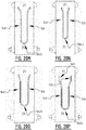
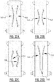
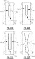
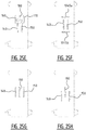
- the absorbent core is provided with a plurality of attachment zones where the top core wrap sheet is attached to the back core wrap sheet.
- the plurality of attachment zones comprises a first and second elongate attachment zone, said first and second elongate attachment zone extending next to each other from a crotch region in the direction of the first and/or second transverse edge.
- the first elongate attachment zone crosses the longitudinal center line in a first crossing point, from the first longitudinal portion to the second longitudinal portion; and the second elongate attachment zone crosses the longitudinal center line in a second crossing point, from the second longitudinal portion to the first longitudinal portion.
- the first and second crossing point may be the same point or a different point, and may be located in the front portion or in the rear portion or on the transverse crotch line between connecting the front portion to the rear portion.
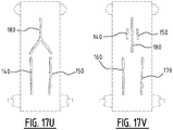
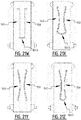
- first and a second elongate attachment zone which are crossing the longitudinal center line, upon wetting of the absorbent core two elongate channels are created.
- the first elongate channel extends from a first left position to a second right side, where the first left position is closer to the first transverse edge than the second right position.
- second elongate channel extends from a second right position to a first left position, where the second right position is closer to the first transverse edge than the first left position.
- first and/or second elongate channel from left to right and/or from right to left, respectively, whilst flowing towards the crotch region or away from the crotch region, improving the liquid distribution, whereupon the liquid can be absorbed by the absorbent material.
- the zones may be longer compared to similar zones extending parallel to the longitudinal center line, resulting in a larger liquid distribution zone.
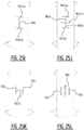
- the first and second crossing point correspond with substantially the same point located on the longitudinal center line. In that manner a connection between the first and the second attachment zone is realized further enhancing the liquid distribution.
- the first and second crossing point may be different points, and the first and the second attachment zone may cross each other at a distance of the longitudinal center line.
- third and fourth elongate attachment zone arranged symmetrically with respect to the first and second elongate attachment zones may be provided, such that the first and second attachment zone cross each other at one side of the longitudinal center line and the third and fourth attachment zone cross each other at another side of the longitudinal center line.
- the first and/or second crossing point are located at a distance of the transverse crotch line.
- the first and/or second crossing point may be located in a front portion. In that way the position of the first and/or second can be optimized e.g. in function of whether the absorbent article is intended for a male or female person.
- the first and/or second crossing point may be located on the transverse crotch line.
- the distance between the first and/or second crossing point and the transverse crotch line is larger than 1% of the length of the absorbent core, preferably larger than 2%, even more preferably larger than 3%.
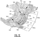
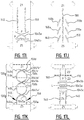
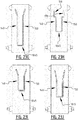
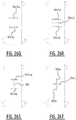
- first crossing points and multiple second crossing points may be provided, wherein these multiple first crossing points may be located a different distances of the transverse crotch line, e.g. two first crossing points, one in the front portion and one in the rear portion, and two second crossing points, one in the front portion (optionally corresponding with the first crossing point in the front portion), and one in the rear portion (optionally corresponding with the first crossing point in the rear portion), see e.g. figure 15P .
- a distance between the transverse crotch line and a transverse center line extending perpendicular on the longitudinal direction of the absorbent core, through the middle of the absorbent core is smaller than 10%, more preferably smaller than 5% of the length of the absorbent core.
- the first elongate attachment zone extends both in the front portion and in the rear portion; and the second elongate attachment zone extends both in the front portion and in the rear portion. In that manner a good liquid distribution from left to right and from front to rear can be obtained.
- the first elongate attachment zone and the second elongate attachment zone are arranged symmetrically with respect to the longitudinal center line of the absorbent core.
- a maximum distance between the first and the second elongate attachment zone is between 15 and 70% of the width of the absorbent core, more preferably between 20 and 50%. In an exemplary embodiment a maximum distance between the first and the second attachment zone in the front portion is different from a maximum distance between the first and the second attachment zone in the rear portion. In that manner the liquid distribution zone may be better adapted to the type of person wearing the absorbent article. For example, for a male person, a maximum distance between the distance between the first and the second attachment zone near a front transverse edge may be larger than a maximum distance between the first and the second attachment zone in a rear portion.
- the length of the first and second attachment zone is larger than 10% of the length of the absorbent core, more preferably larger than 30%, even more preferably larger than 50%.
- the plurality of attachment zones are permanent attachment zones which remain attached when wetted.
- the first attachment zone may be connected to the second attachment zone through a semi-permanent attachment zone, preferably extending in a substantially transverse direction.
- the first and second attachment zone each extends, seen in the transverse direction of the absorbent core, over the transverse distance which is at least 1 mm, preferably at least 3 mm, more preferably at least 4 mm, even more preferably at least 5 mm, most preferably at least 6 mm.
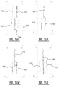
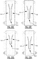
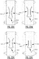
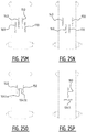
- At least one of said first and second elongate attachment zone comprises a bridge zone (B) allowing a liquid flow between the first and the second longitudinal edge by capillary action through the absorbent material and/or by mass flow, such that upon wetting of the absorbent material, a front and rear channel are created, wherein the bridge zone extends between said front and rear channel; wherein a minimum distance between said front and rear channel is preferably larger than 3 mm more preferably larger than 5 mm.
- first and second channel together form a substantially X-shaped zone.
- legs of the "X" may be interrupted to create one or more bridge zones as defined above.
- the bridge zone extends from the first longitudinal portion of the absorbent core to the second longitudinal portion of the absorbent core; wherein optionally said bridge zone comprises one or more temporary attachments between the top and back core wrap sheet which are configured to detach when wetted; and/or wherein said bridge zone comprises at least one permanent attachment zone in a direction from the first to the second side edge; and/or wherein said bridge zone comprises absorbent material.
- the first and second transverse edge correspond with a front and rear transverse edge
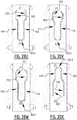
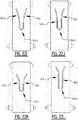
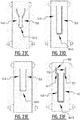
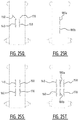
- the plurality of attachment zones further comprises at least one connecting attachment zone connecting said first attachment zone with said second attachment zone.
- first and a second elongate attachment zone which are interconnected by at least one connecting attachment zone
- two elongate channels are created which are interconnected by at least one interconnecting channel which is in liquid communication with the first and second elongate channel.
- liquid can flow from the first elongate channel to the second elongate channel and vice versa, improving the liquid distribution, whereupon the liquid can be absorbed by the absorbent material.
- a connecting attachment zone extends substantially in a transverse direction of the absorbent core. This may be advantageous when the first and second elongate channel extend substantially parallel. In that manner an absorbent core is obtained which may be substantially symmetrical with respect to a longitudinal center axis.
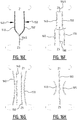
- the connecting attachment zone may be substantially V-shaped or U-shaped, wherein the V-shape or U-shape is arranged such that it is symmetrical with respect to the longitudinal center axis of the absorbent core.
- a first and second channel are created at said first and second elongate attachment zone, respectively, and the first and second channel are directly connected to each other through the at least one connecting attachment zone; wherein a first, second, and at least one connecting channel are created at said first, second, and at least one connecting attachment zone, respectively.
- the at least one connecting attachment zone corresponds with at least one permanent attachment zone which remains attached upon wetting, or at least one semi-permanent attachment zone configured to release after having been in contact with liquid for a predetermined period of time, wherein said predetermined period of time is preferably smaller than 30s.
- the at least one connecting attachment zone comprises one or more straight portions, and/or one or more curved portions.
- the first attachment zone, the second attachment zone, and the at least one connecting attachment zone collectively form a substantially "U” shaped zone, or a substantially “V” shaped zone.
- a U-shape or V-shape provides for a good guidance of the liquid.
- sharp angles may be avoided further improving a good liquid transport from a first elongate attachment zone (one leg) of the U-shaped attachment zone to the second elongate attachment zone (the other leg) of the U-shaped attachment zone.
- liquid may be guided from e.g. a left and right front portion to a center portion in the crotch region.
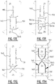
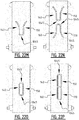
- the first attachment zone, the second attachment zone, and the at least one connecting attachment zone collectively delimit a substantially enclosed region.
- the substantially enclosed region may be a substantially "O" shaped region, or a substantially polygon shaped region, such as a substantially rectangular shaped region, a substantially triangular shaped region, a diamond shaped region, a substantially hexagonal shaped region.
- liquid can be distributed around the boundary of the enclosed region, such that it can be absorbed from the entire boundary by the absorbent material in the enclosed region and by the absorbent material in a region surrounding the enclosed region.
- first attachment zone and the second attachment zone are substantially parallel and extend in a longitudinal direction of the absorbent core.
- an angle between the first attachment zone and a longitudinal direction of the absorbent core and an angle between the second attachment zone and the longitudinal direction of the absorbent core is smaller than 5°.
- the plurality of attachment zones is arranged symmetrically with respect to a longitudinal center axis of the absorbent core extending between the front and rear transverse edge.
- the largest distance between the first and the second attachment zone in the transverse direction is between 15 and 70% of the width of the absorbent core, more preferably between 20 and 50%; wherein preferably the largest distance between the first and the second attachment zone in the transverse direction is between 10 mm and 100 mm, more preferably between 20 mm and 80 mm, even more preferably between 30 mm and 70 mm.
- the first and second attachment zones are permanent attachment zones which remain attached upon wetting, or semi-permanent attachment zones configured to release after having been in contact with liquid for a predetermined period of time, wherein said predetermined period of time is preferably smaller than 30 s.
- the absorbent material comprises cellulosic fluff pulp and/or superabsorbent particles.
- the absorbent core has a first and second longitudinal edge and a first and second transverse edge, wherein the first edge may be the front edge or the rear edge, and the second edge may be the rear edge or the front edge, respectively.
- the absorbent core has a first portion and a second portion on either side of the transverse crotch line.
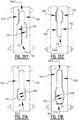
- the first and the second elongate attachment zone extend next to each other, at least in the first portion of the absorbent core in the direction of the first transverse edge.
- the plurality of attachment zones may further comprise a third and a fourth elongate attachment zone extending next to each other, at least in the second portion of the absorbent core, in the direction of the second transverse edge.
- the third and fourth elongate attachment zone may be connected by a connecting attachment zone.
- a first maximum distance between the first and the second attachment zone is preferably bigger than a second maximum distance between the third and the fourth attachment zone.
- the first transverse edge may be a front edge or a rear edge depending on the desired use of the absorbent article.
- the first portion may be a front portion or a rear portion depending on the desired use of the absorbent article.
- the plurality of attachment zones may further comprise a third attachment zone extending from the crotch region in the direction of the second transverse edge, wherein seen in a projection on a transverse direction the third attachment zone is located between the first and the second attachment zone.
- first and second attachment zone may be in the front portion and the third attachment zone may be in the rear portion
- first and second attachment zone may be in the rear portion and the third attachment zone in the front portion.
- the first distance between the first and the second attachment zone may be at least 5%, preferably at least 10% bigger, even more preferably at least 20% bigger than a second distance between the third and the fourth attachment zone.
- This difference may be optimized in function of the desired used. For example, for male persons the difference may be bigger.
- the first and the second elongate attachment zone may each have a front end adjacent to absorbent material and a rear end adjacent to absorbent material or on the transverse crotch line.
- the third and the fourth elongate attachment zone may each have a rear end adjacent to absorbent material and a front end adjacent to absorbent material or on the transverse crotch line (L).
- the first attachment zone may be connected to the third attachment zone: in that case the rear end of the first attachment zone and the front end of the third attachment zone will be on the transverse crotch line.
- the second attachment zone may be connected to the fourth attachment zone: in that case the rear end of the second attachment zone and the front end of the fourth attachment zone will be on the transverse crotch line.
- the first and the second elongate attachment zone may each have a rear end adjacent to absorbent material and a front end adjacent to absorbent material or on the transverse crotch line.
- the third and the fourth elongate attachment zone may each have a front end adjacent to absorbent material and a rear end adjacent to absorbent material or on the transverse crotch line (L).
- the first attachment zone may be connected to the third attachment zone: in that case the front end of the first attachment zone and the rear end of the third attachment zone will be on the transverse crotch line.
- the second attachment zone may be connected to the fourth attachment zone: in that case the front end of the second attachment zone and the rear end of the fourth attachment zone will be on the transverse crotch line.
- the first and the second elongate attachment zone may each have a front end adjacent to absorbent material and a rear end adjacent to absorbent material or on the transverse crotch line.
- the third elongate attachment zone may have a rear end adjacent to absorbent material and a front end adjacent to absorbent material or on the transverse crotch line (L).
- the first attachment zone may be connected to the third attachment zone: in that case the rear end of the first attachment zone and the front end of the third attachment zone will be on the transverse crotch line.
- the second attachment zone may be connected to the third attachment zone: in that case the rear end of the second attachment zone and the front end of the third attachment zone will be on the transverse crotch line.
- the first and the second elongate attachment zone may each have a rear end adjacent to absorbent material and a front end adjacent to absorbent material or on the transverse crotch line.
- the third elongate attachment zone may have a front end adjacent to absorbent material and a rear end adjacent to absorbent material or on the transverse crotch line (L).
- the first attachment zone may be connected to the third attachment zone: in that case the front end of the first attachment zone and the rear end of the third attachment zone will be on the transverse crotch line.
- the second attachment zone may be connected to the third attachment zone: in that case the front end of the second attachment zone and the rear end of the third attachment zone will be on the transverse crotch line.
- the first and the second attachment zone may extend over a length which is less than the length of the third and fourth attachment zone.
- the third and fourth attachment zones which are closer to each other may be longer to extend over a longer part of the crotch region, for example the third and fourth attachment zones may extend both in the first and the second portion of the absorbent core.
- the first and the second attachment zone extend over a length which is at least 5% less, more preferably at least 10% less than the length of the third and fourth attachment zone.
- the first and the second attachment zone extend over a length which is at least 25%, more preferably at least 35%, even more preferably at least 45% of the length of the third and fourth attachment zone.
- the first and the second attachment zone may extend over a length which is less than the length of the third attachment zone.
- the third attachment zone may be longer to extend over a longer part of the crotch region, for example the third attachment zone may extend both in the first and the second portion of the absorbent core.
- the first and the second attachment zone extend over a length which is at least 5% less, more preferably at least 10% less than the length of the third attachment zone.
- the first and the second attachment zone extend over a length which is at least 25%, more preferably at least 35%, even more preferably at least 45% of the length of the third attachment zone.
- the first transverse edge may be a front edge intended to be positioned at a front side of a person, and the second transverse edge may be a rear edge intended to be positioned at a rear side of a person; wherein the first portion of the absorbent core is a front portion and the second portion is a rear portion.
- the first transverse edge may be a rear edge intended to be positioned at a rear side of a person, and the second transverse edge may be a front edge intended to be positioned at a front side of a person; wherein the first portion of the absorbent core is a rear portion and the second portion is a front portion.
- the distance between the first and the second attachment zone may be between 15 and 70% of the width of the absorbent core, more preferably between 20 and 50%.
- the distance between the first and the second attachment zone may be between 10 mm and 100 mm, more preferably between 20 mm and 80 mm, preferably between 30 mm and 70 mm.
- the distance between the third and the fourth attachment zone may be between 5 and 60% of the width of the absorbent core, more preferably between 10 and 40%.
- the distance between the third and the fourth attachment zone may be between 5 mm and 60 mm, more preferably between 10 mm and 50 mm, even more preferably between 15 mm and 40 mm.
- the length of the first and the second attachment zone may be larger than 5% of the length of the absorbent core; preferably larger than 10%, more preferably larger than 15%, e.g. larger than 20% or even larger than 30% or 40% of the length of the absorbent core.
- the length of the third and the fourth attachment zone may be larger than 5% of the length of the absorbent core; preferably larger than 10%, more preferably larger than 15%, e.g. larger than 20%.
- the length of the third attachment zone may be larger than 5% of the length of the absorbent core; preferably larger than 10%, more preferably larger than 15%, e.g. larger than 20%.
- the length of the third and the fourth attachment zone may be larger than the length of the first and the second attachment zone, preferably at least 10% larger, more preferably at least 20% larger.
- a projection of the first and second attachment zone does not overlap with a projection of the third and fourth attachment zone.
- the third and fourth attachment zone may extend in between the first and second attachment zone.
- a projection of the first and second attachment zone does not overlap with a projection of the third attachment zone.
- the third attachment zone may extend in between the first and second attachment zone.
- first attachment zone may be separated from the third attachment zone by absorbent material
- second attachment zone may be separated from the fourth attachment zone by absorbent material. In that manner a capillary bridge is created between the first and second attachment zones on the one hand and the third and fourth attachment zones on the other hand.
- first attachment zone may be connected to the third attachment zone through a first semi-permanent attachment zone and the second attachment zone may be connected to the fourth attachment zone through a second semi-permanent attachment zone.
- Such semi-permanent attachment zones are configured to be detached upon wetting, so that liquid can flow in a transverse direction through the absorbent material of the absorbent core.
- one or more permanent or semi-permanent transverse attachment zones may be provided to further improve the liquid distribution in the transverse direction.
- the absorbent material may comprise cellulosic fluff pulp and/or superabsorbent particles.
- the absorbent material may be substantially fluffless.
- substantially no absorbent material is present in the plurality of attachment zones.
- the first, second, third and fourth attachment zones are permanent attachment zones which remain attached upon wetting.
- the first, second, and third attachment zones are permanent attachment zones which remain attached upon wetting.
- a distance between the transverse crotch line and a transverse center line extending perpendicular on the longitudinal direction of the absorbent core, through the middle of the absorbent core, may be smaller than 10%, more preferably smaller than 5% of the length of the absorbent core.
- the length of the first and the second attachment zone may be larger than 30 mm, preferably larger than 40 mm, more preferably larger than 50 mm.
- the length of the third and the fourth attachment zone may be larger than 30 mm, preferably larger than 40 mm, more preferably larger than 50 mm.
- the first and second attachment extend, seen in the transverse direction of the absorbent core, over the transverse distance which may be at least 1 mm, preferably at least 3 mm, more preferably at least 4 mm, even more preferably at least 5 mm, most preferably at least 6 mm.
- the third attachment zone and the fourth attachment zone may be substantially parallel and extend in a longitudinal direction of the absorbent core; or an angle between the third attachment zone and a longitudinal direction of the absorbent core and an angle between the fourth attachment zone and the longitudinal direction of the absorbent core may be smaller than 5°. Also, in the embodiment of claim 2, the third attachment zone may extend in a longitudinal direction of the absorbent core; or an angle between the third attachment zone and a longitudinal direction of the absorbent core may be smaller than 5°.
- a position and/or shape of one or more attachment zones of the plurality of attachment zones may be indicated by means of a distinguishable color and/or colored pattern.
- the position and/or shape of one or more of the plurality of attachment zones may be indicated by means of a printed ink layer.
- the distinguishable color and/or colored pattern may be provided on at least one of the topsheet, the top core wrap sheet, the backsheet and the back core wrap sheet.
- the plurality of attachment zones together may cover at least 30 %, preferably at least 40% of a length of the absorbent core.
- the difference between the first distance and the second distance may be less than 20% of the width of the absorbent article, preferably less than 10%, e.g. between 0 and 8% or between 1 and 5%, wherein the width is measured in the transverse direction of the absorbent core.
- top core wrap sheet and the bottom core wrap sheet may be formed as one integral sheet or may comprise separate portions around the absorbent material.
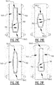
- the absorbent core comprises subsequently a first, second, third, fourth and fifth zone.
- the absorbent core comprises a front portion extending between the front edge and a transverse crotch line of the absorbent core, and a rear portion extending between the rear edge and the transverse crotch line of the absorbent core.
- the first, second and third zone extend in the front portion of the absorbent core and the fourth and fifth zone extend in the rear portion.
- the at least one connecting attachment zone connecting the first and second elongate attachment zone extend in the second, third or fourth zone.
- the second and/or third zone comprises at least one front connecting attachment zone connecting a first elongate front attachment zone and a second elongate front attachment zone; and/or the fourth zone comprises at least one rear connecting attachment zone connecting a first elongate rear attachment zone and a second elongate rear attachment zone.
- the first and fifth zone substantially no permanent attachment zones with a liquid guidance or distribution function are present.
- the first and fifth zones may comprise small local attachment points provided for other reasons that liquid distribution management.
- the second zone comprises at least a first elongate front attachment zone of the plurality of attachment zones, said first front attachment zone extending from an edge of the first zone in the direction of the third zone.
- at least the fourth zone comprises at least a first rear elongate attachment zone of the plurality of attachment zones, said first rear attachment zone extending from an edge of the fifth zone in the direction of the third zone.
- At least one of said second, third and fourth zone comprises a bridge zone (B) allowing a liquid flow between the first and the second side edge by capillary action through the absorbent material and/or by mass flow.
- the liquid path through the bridge zone may be any path going from an area near the first side edge to an area near the second edge.
- the distance between the transverse crotch line and the transverse center line passing through the middle of the core is less than 10% of the length of the core.
- the first rear attachment zone may extend in the third zone, i.e. in the front portion of the absorbent core.
- the first front attachment zone may extend in the third and/or the fourth zone, i.e. in the rear portion of the absorbent core.
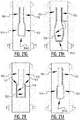
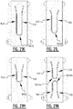
- channels are created when the absorbent core is wetted.
- a bridge zone in at least one of the second, third and fourth zone, notwithstanding the creation of a channel, liquid taken up in absorbent material near the first side edge may migrate by capillary action and/or mass flow in the direction of the second side edge.
- the liquid is on the one hand distributed by the channels formed by the at least one front attachment zone and at least one rear attachment zone, and on the other hand allowed to be transported from one side edge to the other side edge by capillary action and/or by mass flow via the bridge zone. This is advantageous, especially when a person wearing the absorbent article is lying down on its side.
- the liquid when lying down the liquid may flow towards one side edge by gravity. This will cause a swelling of the absorbent material near that side edge, and the bridge zone will allow the liquid to flow towards the other side edge against the gravity force by capillary action.
- the channels will be able to provide for a fast liquid distribution through the second, third and fourth zone.
- the bridge zone extends between the first front attachment zone and the first rear attachment zone, such that upon wetting of the absorbent material, a front and rear channel are created at said first front and rear attachment zone, respectively, wherein the bridge zone extends between said front and rear channel.
- the bridge zone may comprise secondary temporary attachment zones which loosen upon wetting, whilst the first front attachment zone and the first rear attachment zone remain attached upon wetting.
- the bridge zone may comprise attachment zones extending between the first side edge and the second side edge to promote a mass flow action between an area near the first side edge to an area near the second side edge, wherein said areas are located at opposite sides of the first front/rear attachment zone.
- the liquid path through the bridge zone may be any path going from an area near the first side edge to an area near the second edge. It may be a straight transverse zone, but it may also be a curved zone, or a partially straight and partially curved zone.
- a minimum distance between the first front attachment zone and the first rear attachment zone is larger than 3 mm, more preferably larger than 5 mm, even more preferably larger than 8 mm. In that way a sufficient flow can be guaranteed. This minimum distance (which is related to the capillary flow and/or mass flow) may be varied depending on the size of the absorbent article.
- the bridge zone is configured to cause a capillary flow so that a flow against the gravity force is possible.
- the first rear elongate attachment zone extends into the third zone. In that manner a continuous channel is formed between the front and the rear portion of the absorbent core.
- the first zone extends over a length corresponding with at least 5%, more preferably at least 10% of the length of the absorbent core seen in the longitudinal direction.
- the fifth zone extends over a length corresponding with at least 10% of the length of the absorbent core seen in the longitudinal direction, preferably at least 20%, more preferably at least 25%.
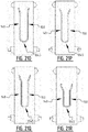
- the absorbent material in the first zone and the fifth zone will swell upon wetting and created bands at both sides of the crotch region. Such bands will create a barrier such that it is more difficult for any liquid in the crotch region to flow out of the absorbent core.
- the second, the third and/or the fourth zone each extends over a length corresponding with at least 10% of the length of the absorbent core, seen in the longitudinal direction, preferably at least 15%.
- the front and rear attachment zone when projected on the longitudinal direction extend over at least 70%, more preferably at least 80% of the total length of the second, the third and/or the fourth zone. In that manner a good channel creation with sufficient liquid distribution through the absorbent core is achieved.
- the first front attachment zone extends in a longitudinal direction of the absorbent core; or an angle between the first front attachment zone and a longitudinal direction of the absorbent core may be smaller than 5°.
- the first rear attachment zone extends in a longitudinal direction of the absorbent core; or an angle between the first rear attachment zone and a longitudinal direction of the absorbent core may be smaller than 5°.
- the length of the first front attachment zone is larger than 5% of the length of the absorbent core; preferably larger than 10%, more preferably larger than 15%; and/or wherein the length of the first rear attachment zone is larger than 5% of the length of the absorbent core, preferably larger than 10%, more preferably larger than 15%.
- the length of the first front attachment zone is at least 10%, more preferably at least 25%, even more preferably at least 35%, or even at least 50 or 75% of the length of the first rear attachment zone.
- the length of the first rear attachment zone is at least 10%, more preferably at least 25%, even more preferably at least 35%, or even at least 50 or 75% of the length of the first front attachment zone.
- the second zone comprises a second front attachment zone extending next to the first front attachment zone, seen in the longitudinal direction.
- the first front attachment zone and the second front attachment zone are arranged symmetrically with respect to a longitudinal center line of the absorbent core.
- the distance between the first and the second front attachment zone is between 20 mm and 70 mm, more preferably between 30 mm and 60 mm, even more preferably between 40 mm and 55 mm.
- the distance between the first and the second front attachment zone is between 15 and 70% of the width of the absorbent core, more preferably between 20 and 50%. Especially for male persons, this distance is preferably sufficiently large such that urine is captured mainly in the area between the first front attachment zone and the second front attachment zone.
- the first front attachment zone and the second front attachment zone may be substantially parallel and may extend in a longitudinal direction of the absorbent core; or an angle between the first front attachment zone and a longitudinal direction of the absorbent core and an angle between the second front attachment zone and the longitudinal direction of the absorbent core may be smaller than 5°.
- the first and second front attachment zones may diverge in the direction of the first zone.
- the fourth zone comprises a second rear attachment zone extending next to the first rear attachment zone, seen in the longitudinal direction, said second rear attachment zone extending preferably into the third zone.
- the first rear attachment zone and the second rear attachment zone are arranged symmetrically with respect to a longitudinal center line of the absorbent core.
- the distance between the first and the second rear attachment zone is between 10 mm and 50 mm, preferably between 15 mm and 40 mm, more preferably between 20 mm and 30 mm.
- the distance between the first and the second rear attachment zone is between 5 and 60% of the width of the absorbent core, more preferably between 10 and 40%.
- the first rear attachment zone and the second rear attachment zone are substantially parallel and extend in a longitudinal direction of the absorbent core; or an angle between the first rear attachment zone and a longitudinal direction of the absorbent core and an angle between the second rear attachment zone and the longitudinal direction of the absorbent core is smaller than 5°.
- the first and second rear attachment zones may diverge in the direction of the fifth zone.
- a first smallest distance (d12) between the first and the second front attachment zone is bigger than a second smallest distance (d34) between the first and the second rear attachment zone, more preferably at least 10% bigger, even more preferably at least 15% bigger.
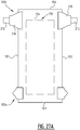
- the channels formed by the first and the second rear attachment zone will be closer to each other in the center of the crotch region making the absorbent article more agreeable to wear, also when wetted, and will give the absorbent article a tub-shape when wetted, see further.
- the channels created by the first and the second front attachment zone will be further away from each other to obtain a good liquid distribution, especially for male persons.
- the first and the second front attachment zone extend in a longitudinal direction of the absorbent core over a length which is less than the length of the first and second rear attachment zone, more preferably at least 10% less, even more preferably at least 15% less.
- the first and the second front attachment zone can extend from the fourth zone into the third zone such that the absorbent article fits better to the body of the wearer.
- the bridge zone extends from a first portion of the absorbent core, preferably in the second or third zone, to a second portion of the absorbent core, preferably in the second or third zone, wherein the first portion is defined between the first side edge and a longitudinal center axis (CL) of the absorbent core and the second portion is defined between the second side edge and the longitudinal center axis (CL) of the absorbent core.
- first portion is defined between the first side edge and a longitudinal center axis (CL) of the absorbent core
- the second portion is defined between the second side edge and the longitudinal center axis (CL) of the absorbent core.
- the length of the first front attachment zone is larger than 30 mm, more preferably larger than 40 mm, even more preferably larger than 50 mm.
- the length of the first rear attachment zone is larger than 30 mm, more preferably larger than 40 mm, even more preferably larger than 50 mm.
- said plurality of attachment zones are permanent attachment zones which remain attached when wetted.
- said plurality of attachment zones extend, seen in the transverse direction of the absorbent core, over the transverse distance which is at least 1 mm, preferably at least 3 mm, more preferably at least 4 mm, even more preferably at least 5 mm, most preferably at least 6 mm. In that manner the channels created upon wetting will be sufficiently wide to cause a good liquid distribution.
- the bridge zone comprises one or more temporary attachments which are configured to detach when wetted. In that manner, upon wetting the one or more temporary attachments may first function to guide a mass flow of the liquid, whereupon, after loosening a capillary flow through the absorbent material is made possible.
- the bridge zone comprises at least one permanent attachment zone in a direction from the first to the second side edge, e.g. in a transverse direction.
- the top core wrap sheet is attached to the back core wrap sheet through permanent and semi-permanent attachment portions, said semi-permanent portions being configured to release after having been in contact with liquid whilst said permanent portions are configured not to release after having been in contact with liquid.
- the absorbent material comprises cellulosic fluff pulp. In an exemplary embodiment, the absorbent material comprises superabsorbent polymer particles.
- the absorbent core may be substantially fluffless.
- a position and/or shape of one or more attachment zones of the plurality of attachment zones is indicated by means of a distinguishable color and/or colored pattern.
- the position and/or shape of one or more of the plurality of attachment zones is indicated by means of a printed ink layer.
- the distinguishable color and/or colored pattern is provided on at least one of the topsheet, the top core wrap sheet, the backsheet and the back core wrap sheet.
- the plurality of attachment zones together covers at least 30 %, preferably at least 40% of a length of the absorbent core.
- a method for manufacturing an absorbent article may comprise the steps of:
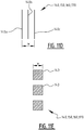
- the attaching is done by applying pressure and heat on the top core wrap sheet material and/or the back core wrap sheet material in the areas where substantially no absorbent material is present.
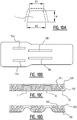
- a binder is applied to at least one portion of the first sheet material at a distance from the intended position of the first and second attachment zones, before the absorbent material is applied on said first sheet material and a binder is applied to at least one portion of the second sheet material before it is applied on top of the absorbent material on the first sheet material.
- the at least one portion of the first sheet material and the at least one portion of the second sheet material are chosen such that in the application and attachment of the first sheet material to the second sheet material the plurality of portions are complementary, wherein preferably substantially the entire surface of the absorbent article is provided with binder on either the first sheet material or the second sheet material.
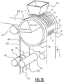
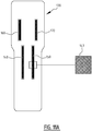
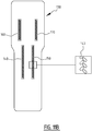
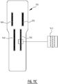
- the attaching is done by a rotating member which is provided with at least a first and a second seal rib dimensioned for applying pressure and heat on the top core wrap sheet material and/or the back core wrap sheet material in the areas where substantially no absorbent material is present in order to create the first and second attachment zone, respectively.
- a method for manufacturing an absorbent article may comprise:
- the attaching may be done by applying pressure and heat on the top core wrap sheet material and/or the back core wrap sheet material in the areas where substantially no absorbent material is present.
- the attaching may be done by a rotating member which is provided with at least a first seal rib dimensioned for applying pressure and heat on the top core wrap sheet material and/or the back core wrap sheet material in the areas where substantially no absorbent material is present in order to create the first attachment zone.
- a first binder may be applied to at least one portion of the first sheet material at a distance from the intended position of the first attachment zone, prior to step b, and a second binder may be applied to at least one portion of the second sheet material prior to step c.
- the at least one portion of the first sheet material and the at least one portion of the second sheet material are chosen such that in the application and attachment of the first sheet material to the second sheet material the plurality of portions are complementary, wherein preferably substantially the entire surface of the absorbent article is provided with binder on either the first sheet material or the second sheet material.
- the first binder applied on at least one portion of the first sheet material may be different from, preferably less strong than, the second binder applied on the at least one portion of the second sheet material.
- the binder may be applied on at least one portion of the first sheet material as a first layer having a first thickness, and on the at least one portion of the second sheet material as a second layer having a second thickness which is different from, preferably higher than, the first thickness.
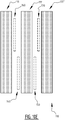
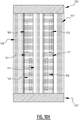
- the binder may be applied on the first sheet material as a plurality of parallel first longitudinal stripes and on the second sheet material as a plurality of parallel second longitudinal stripes, wherein preferably a second longitudinal stripe thereof is located in between two first longitudinal stripes of the plurality of first longitudinal stripes.
- an absorbent article which is manufactured according to any one of the method embodiments as described above can be distinguished from absorbent articles which are manufactured according to another method. More in particular, the above described manner of applying layers of binder, such as glue, is distinguishable in an absorbent article end product by examining the bonds within the particular absorbent article by means of any one of the following: color analysis, UV analysis, chemical analysis, and the like. In other words, by examining the absorbent article end product, the skilled person can determine which type of binder has been used, where the particular binder has been applied, how many layers of binder have been applied, etc.
- an edge barrier refers to one or more than one edge barrier.
- Absorbent article refers to devices that absorb and contain bodily exudates, and more specifically, refers to devices that are placed against or in proximity to the body of the wearer to absorb and contain the various liquids discharged from the body.
- Absorbent articles include but are not limited to feminine hygiene garments, baby diapers and pants, adult incontinence garments, various diaper and pants holders, liners, towels, absorbent inserts and the like.
- Absorbent core refers to a three-dimensional part of the absorbent structure, comprising liquid-absorbing material, useful to permanently absorb and/or retain bodily exudates.
- Absorbent component refers to a structural constituent of an absorbent article, e.g., a piece of an absorbent core, such as one of multiple pieces in a multi-piece absorbent core.
- Absorbent element refers to a part of a functional constituent of an absorbent structure, e.g., a acquisition layer, a dispersion layer, core layer or a release structure formed of a material or materials having particular liquid handling characteristics suitable for the specific function.
- Absorbent fibrous polymer material refers to an absorbent polymer material which is in threadlike from such as fibers, filaments, and the like so as to be less flowable in the dry state than particulates.
- Absorbent insert refers to a device adapted for insertion into an "Absorbent layer” as used herein refers to a term referring to a discrete, identifiable sheet-like or web-like element of an absorbent article which may remain detached and relatively movable with respect to another such element or may be attached or joined so as to remain permanently associated with another such element.
- Each absorbent layer may itself include a laminate or combination of several layers, sheets and/or webs of similar or diverse compositions.
- ABSAP Ultrasorbent polymer material
- AGM absorbent gelling material
- AGM absorbent gelling material
- SAP super absorbent polymer
- any suitable particulate e.g., flaked, particulate, granular, or powdered
- fibrous cross linked polymeric materials that can absorb at least 5 times and preferably at least about 10 times or more its weight of an aqueous 0.9% saline solution as measured using the Centrifuge Retention Capacity test (EDANA 441.2-01).
- Absorbent polymer material area refers to the area of the absorbent structure wherein adjacent layers are separated by a multiplicity of absorbent polymer material. Incidental contact areas between these adjacent layers within the absorbent particulate polymer material area may be intentional (e.g bond area's) or unintentional (e.g. manufacturing artifacts).
- Absorbent particulate polymer material refers to an absorbent polymer material which is in particulate form such as powders, granules, flakes and the like so as to be flowable in the dry state.
- Absorption rate refers to the rate of absorption of liquid, i.e. the amount of liquid which is absorbed per unit of time, typically by an absorbent component, element and/or absorbent layer of the absorbent article, structure and/or core.
- Acquisition layer refers to the layer overlying the absorbent core having a faster liquid uptake and/or distribution capability.
- Absorbency is the ability of a material to take up fluids by various means including capillary, osmotic, solvent, chemical and/or other action.
- “Adult incontinence garment” as used herein refers to absorbent articles intended to be worn by incontinent adults, for absorbing and containing bodily exudates.
- Adhesion refers to the force that holds different materials together at their interface.
- Adhesive refers to a material, which may or may not be flowable in solution or when heated, that is used to bond materials together.
- Adsorption refers to the process by which a liquid is taken up by the surface of a material.
- Airlaying refers to forming a web by dispersing fibers or particles in an air stream and condensing them from the air stream onto a moving screen by means of a pressure and/or vacuum; a web of fibers produced by airlaying is herein referred to an "airlaid”; an airlaid web bonded by one or more techniques to provide fabric integrity is herein referred to an "airlaid nonwoven”.
- Apparent density refers to the basis weight of the sample divided by the caliper with appropriate unit conversions incorporated therein. Apparent density used herein has the unit g/cm 3 .
- Body diaper refers to absorbent articles intended to be worn by children, for absorbing and containing bodily exudates which the user draws up between the legs and fastens about the waist of the wearer.
- Body pants refers to absorbent articles marketed for use in transitioning children from diapers to underwear intended to cover the lower torso of children, so as to absorb and contain body exudates which article is generally configured like a panty garment and manufactured with a completed waist encircling portion, thereby eliminating the need for the user to fasten the article about the waist of the wearer.
- Back region refers to the portion of an absorbent article or part thereof that is intended to be positioned proximate the back of a wearer.
- Backing refers to a web or other material that supports and reinforces the back of a product.
- Basis weight is the weight per unit area of a sample reported in grams per square meter, g/m 2 or gsm.
- Bodily exudates "body exudates”, “bodily fluids”, “body fluids”, “bodily discharges”, “body discharges”, “fluid(s)”, “ liquid(s)”, “fluid(s) and liquid(s) and the like as used herein are used interchangeably and refer to, but are not limited to urine, blood, vaginal discharges, breast milk, sweats and fecal matter.
- Binder "adhesive”, “glue”, “resins”, “plastics” and the like as used herein are used interchangeably and refer to substances, generally in a solid form (e.g. powder, film, fiber) or as a foam, or in a liquid form (e .g. emulsion, dispersion, solution) used for example by way of impregnation, spraying, printing, foam application and the like used for attaching or bonding functional and/or structural components, elements and materials, for example including heat and/or pressure sensitive adhesives, hot-melts, heat activated adhesives, thermoplastic materials, chemical activated adhesives/solvents, curable materials and the like.
- Bond strength refers to the amount of adhesion between bonded surfaces. It is a measure of the stress required to separate a layer of material from the base to which it is bonded.
- Chassis refers to a foundational constituent of an absorbent article upon which the remainder of the structure of the article is built up or overlaid, e.g., in a diaper, the structural elements that give the diaper the form of briefs or pants when configured for wearing, such as a backsheet, a topsheet, or a combination of a topsheet and a backsheet.
- Cellulose fibers refers to naturally occurring fibers based on cellulose, such as, for example cotton, linen, etc; wood pulp fibers are one example of cellulose fibers; man-made fibers derived from cellulose, such as regenerated cellulose (rayon), or partially or fully acetylated cellulose derivatives (e.g. cellulose acetate or triacetate) are also considered as cellulose fibers.
- Cluster or the like as used herein refers to an agglomeration of particles and/or fibers.
- “Chemically stiffened fibers”, chemically modified fibers”, “chemically cross-linked fibers”, “curly fibers” and the like as used herein are used interchangeably and refer to any fibers which have been stiffened by chemical means to increase stiffness of the fibers under both dry and aqueous conditions, for example by way of addition of chemical stiffening agents (e.g. by coating, impregnating, etc), altering the chemical structure of the fibers themselves (e.g. by cross-linking polymer chains, etc) and the like.
- Cohesion refers to the resistance of similar materials to be separated from each other.
- Computer refers to chambers, cavities, pockets and the like.
- Crossstock refers to a lightweight non-woven material used to contain and conceal an underlying absorbent core material; examples are the facing layer or materials that cover the absorbent cores of feminine hygiene garment s, baby diapers and pants and adult incontinence garments.
- Rotch region of an absorbent article refers to about 50% of the absorbent article's total length (i.e., in the y-dimension), where the crotch point is located in the longitudinal center of the crotch region. That is, the crotch region is determined by first locating the crotch point of the absorbent article, and then measuring forward and backward a distance of 25% of the absorbent article's total length.
- Cross direction (CD) Cross direction
- lateral lateral
- transverse and the like as used herein are used interchangeably and refer to a direction which is orthogonal to the longitudinal direction and includes directions within ⁇ 45° of the transversal direction.
- “Curing” as used herein refers to a process by which resins, binders or plastics are set into or onto fabrics, usually by heating, to cause them to stay in place; the setting may occur by removing solvent or by cross-linking so as to make them in soluble.
- Diaper "Diaper”, "conventional diaper”, “diaper-like”, “diaper-like garment” and the like as used herein are used interchangeably and refer to disposable absorbent articles, which typically include a front waist portion and a back waist portion which may be releasable connected about the hips of the wearer during use by conventional fasteners such as adhesive tape fasteners or hook and loop type fasteners.
- conventional fasteners such as adhesive tape fasteners or hook and loop type fasteners.
- the article is positioned between the legs of the wearer and the fasteners are releasable attached to secure the back waist portion to the front waist portion of the diaper, thereby securing the diaper about the waist of the wearer.
- the front waist portion and a back waist portion are connected by relatively non-stretchable or stretchable members (the term “stretchable” as used herein refers to materials that are extensible when forces are applied to the material, and offer some resistance to extension). Hence, such articles are generally not configured to be pulled up or down over the hips of the wearer when the fasteners are attached.
- Dispossion layer refers to the layer overlying the absorbent core having a faster liquid uptake and dispersion capability.
- Disposable is used herein to describe articles that are generally not intended to be laundered or otherwise restored or reused (i.e., they are intended to be discarded after a single use and, preferably, to be recycled, composted or otherwise disposed of in an environmentally compatible manner).
- “Drylaying” as used herein refers to a process for making a nonwoven web from dry fiber; these terms apply to the formation of carded webs, as well as to the air laying formation of random webs; a web of fibers produced by drylaying is herein referred to as a "drylaid”; a drylaid web bonded by one or more techniques to provide fabric integrity is herein referred to a “drylaid nonwoven”.
- “Dry strength” as used herein refers to the strength of ajoint determined in dry state conditions, immediately after drying under specified conditions or after a period of conditioning in the standard laboratory atmosphere.
- Essentially cellulose free or “little to no cellulose fibers” as used herein refers to an absorbent article, structure, core component and/or element containing less than 20% by weight cellulosic fibers, less than 10% cellulosic fibers, less than 5% cellulosic fibers, no cellulosic fibers, or no more than an immaterial amount of cellulosic fibers which do not materially affect the thinness, flexibility or absorbency thereof.
- Essentially fluffless or “little to no fluff pulp” as used herein refers to an absorbent article, structure, core, component and/or element containing less than 20% by weight fluff pulp, less than 10% fluff pulp, less than 5% fluff pulp, no fluff pulp, or no more than an immaterial amount of fluff pulp which do not materially affect the thinness, flexibility or absorbency thereof.
- Fabric refers to a sheet structure made from fibers, filaments and/or yarns.
- “Feminine hygiene garments” as used herein refer to absorbent hygiene articles intended to be worn by woman, for absorbing and containing body exudates.
- Fiber refers to the basic threadlike structure from which nonwovens, yarns and textiles are made. It differs from a particle by having a length at least 4 times its width; "Natural fibers” are either of animal (wool, silk), vegetable (cotton, flax, jute) or mineral (asbestos) origin, while “Man-made fibers” may be either polymers synthesized from chemical compounds (polyester, polypropylene, nylon, acrylic etc.) or modified natural polymers (rayon, acetate) or mineral (glass). "Fiber” and “filament” are used interchangeably.
- Fiber pulp or "Pulp fluff” as used herein refers to wood pulp specially prepared to be drylaid.
- the fibers can be either natural or synthetic or a combination thereof.
- Front region refers to the portion of an absorbent article or part thereof that is intended to be positioned proximate the front of a wearer.
- Garment facing layer refers to elements of the chassis that form the outer surface of the absorbent article, such as the backsheet, the side panels, the waist fasteners, and the like, when such elements are present.
- Heat activated adhesive refers to a dry adhesive that is rendered tacky or fluid by application of heat or heat and pressure to the assembly.
- Heat sealing adhesive refers to a thermoplastic adhesive which is melted between the adherent surfaces by heat application to one or both of the adjacent adherent surfaces.
- High loft refers to general term of low density, thick or bulky fabrics.
- Hot-melt adhesive refers to a solid material that melts quickly upon heating, then sets to a firm bond upon cooling; used for almost instantaneous bonding.
- Hydrophilic refers to having an affinity for being wetted by water or for absorbing water.
- Hydrophilic refers to lacking the affinity for being wetted by water or for absorbing water.
- Immobilization layer refers to a layer able to be applied to the absorbent polymer material or absorbent polymer material area with the intent to gather, bond and/or immobilize absorbent material and/or absorbent layer.
- Join, “joined” and “joining” as used herein refers to encompassing configurations wherein an element is directly secured to another element by affixing the element directly to the other element, as well as configurations wherein the element is indirectly secured to the other element by affixing the element to an intermediate member or members which in turn is or are affixed to the other element.
- Knitting refers to the technique for interlocking loops of fibers with needles or similar devices.
- Layer refers to identifiable components of the absorbent article, and any part referred to as a “layer” may actually comprise a laminate or combination of several sheets or webs of the requisite type of materials.
- layer includes the terms “layers” and “layered.” “Upper” refers to the layer of the absorbent article which is nearest to and/ or faces the wearer facing layer; conversely, the term “lower” refers to the layer of the absorbent article which is nearest to and/or faces the garment facing layer.
- Layer is three dimensional structure with a x dimension width, y dimension length, and z-dimensions thickness or caliper, said x-y dimensions being substantially in the plane of the article, however it should be noted that the various members, layers, and structures of absorbent articles according to the present invention may or may not be generally planar in nature, and may be shaped or profiled in any desired configuration .
- Machine direction (MD) "longitudinal” and the like as used herein are used interchangeably and refer to a direction running parallel to the maximum linear dimension of the structure and includes directions within ⁇ 45° of the longitudinal direction.
- Major surface refers to a term used to describe the surfaces of greatest extent of a generally planar or sheet-like structural element and to distinguish these surfaces from the minor surfaces of the end edges and the side edges, i.e., in an element having a length, a width, and a thickness, the thickness being the smallest of the three dimensions, the major surfaces are those defined by the length and the width and thus having the greatest extent.
- Mass flow refers to the f low of a liquid f rom one absorbent element or component to another absorbent element or component by channel flow action.
- Mechanism bonding refers to a method of bonding fibers by entangling them. This can be achieved by needling, stitching with fibers or by the use of high-pressure air or water jets and the like.
- Nonwoven refers to manufactured sheet, web or batt of directionally or randomly orientated fibers, bonded by friction, and/or cohesion and/or adhesion, excluding paper and products which are woven, knitted, tufted, stitch-bonded incorporating binding yarns or filaments, or felted by wet-milling, whether or not additionally needled.
- the fibers may be of natural or man-made origin and may be staple or continuous filaments or be formed in situ.
- Nonwoven fabrics can be formed by many processes such as melt blowing, spun bonding, solvent spinning, electrospinning, and carding. The basis weight of nonwoven fabrics is usually expressed in grams per square meter (gsm).
- Pant "training pant”, “closed diapers”, “prefastened diapers”, “pull-on diapers” and “diaperpants” and the like as used herein are used interchangeably and refer to absorbent articles which are typically applied to the wearer by first leading the feet into the respective leg openings and subsequently pulling the pants from the feet to waist area over the hips and buttocks of the wearer and which are capable of being pulled up or down over the hips of the wearer.
- Such articles may include a front waist portion and a back waist portion which may be connected about the hips of the wearer by integral or releasable members.
- a pant may be preformed by any suitable technique including, but not limited to, joining together portions of the article using refastenable and/or nonrefastenable bonds (e.g., seam, weld, adhesive, cohesive bond, fastener, etc.).
- a pant may be preformed anywhere along the circumference of the article (e.g., side fastened, front waist fastened).
- Polymer refers to but is not limited to, homopolymers, copolymers, such as for example, block, graft, random and alternating copolymers, terpolymers, etc. and blends and modifications thereof. Unless otherwise specifically limited, the term “polymer” includes all possible spatial configurations of the molecule and include, but are not limited to isotactic, syndiotactic and random symmetries.
- Rear refers to the portion of an absorbent article or part thereof that is intended to be positioned proximate the back of the wearer.
- Release structure As used herein are used interchangeably and refer to a structure in fluid communication with the absorbent core having a larger relative liquid absorption capacity and/or rate allowing it to quickly take up, temporarily hold and releasing liquids.
- Resin refers to a solid or semisolid polymeric material.
- Thermobonding refers to a method of bonding fibers by the use of heat and/or high-pressure.
- Thermoplastic refers to polymeric materials that have a melting temperature and can flow or be formed into desired shapes on the application of heat at or below the melting point.
- Ultrasonic refers to the use of high frequency sound to generate localized heat through vibration thereby causing thermoplastic fibers to bond to one another.
- Water-absorbing “liquid-absorbing”, “absorbent”, “absorbing” and the like as used herein are used interchangeably and refer to compounds, materials, products that absorb at least water, but typically also other aqueous fluids and typically other parts of bodily exudates such as at least urine or blood.
- Weight facing layer refers to elements of the chassis that form the inner surface of the absorbent article, such as the topsheet, the leg cuffs, and the side panels, etc., when such elements are present.
- Weighting refers to the process of interlacing two or more sets of yarns at right angles to form a fabric; a web of fibers produced by weaving is herein referred to as a "woven".
- Web material refers to an essentially endless material in one direction, i.e. the longitudinal extension or the length, or the x- direction in Cartesian coordinates relative to the web material. Included in this term is an essentially unlimited sequence of pieces cut or otherwise separated from an essentially endless material.
- the web materials will have a thickness dimension (i.e. the z-direction) which is significantly smaller than the longitudinal extension (i.e. in x-direction).
- the width of web materials (they-direction) will be significantly larger than the thickness, but less than the length.
- the thickness and the width of such materials is essentially constant along the length of the web.
- such web materials may be cellulosic fiber materials, tissues, woven or nonwoven materials and the like.
- web materials are supplied in roll form, or on spools, or in a folded state in boxes. The individual deliveries may then be spliced together to form the essentially endless structure.
- a web material may be composed of several web materials, such as multilayer non-woven, coated tissues, nonwoven/film laminates. Web materials may comprise other materials, such as added binding material, particles, hydrophilizing agents and the like.
- Weight burst strength is a measure of a layer's ability to absorb energy, when wet and subjected to deformation normal to the plane of the web.
- Weight strength refers to the strength of a joint determined immediately after removal from a liquid in which it has been immersed under specified conditions of time, temperature and pressure. The term is commonly used in the art to designate strength after immersion in water.
- Weighting refers to the forming a web from an aqueous dispersion of fibers by applying modified paper making techniques; a web of fibers produced by wetlaying is herein referred to as a "wetlaid”.
- Wood pulp refers to cellulosic fibers used to make viscose rayon, paper and the absorbent cores of products such as feminine hygiene garments, baby diapers and pants and adult incontinence garments.
- X-y dimension refers to the plane orthogonal to the thickness of the article, structure or element.
- the x- and y-dimensions correspond generally to the width and length, respectively, of the article, structure or element.
- Z-dimension refers to the dimension orthogonal to the length and width of the article, structure or element.
- the z-dimension corresponds generally to the thickness of the article, structure or element.
- FIG 1A, 1B , 1C and 1D illustrate an exemplary embodiment of an absorbent article, here a diaper.
- Figure 1B shows the absorbent article in its flat out, un-contracted state with the wearer side facing the viewer.
- the absorbent article may also be a pant or an adult incontinence garment or the like.
- the absorbent article 100 comprises a liquid pervious topsheet, a liquid impervious backsheet, and an absorbent core 130 positioned in between the topsheet and the backsheet.
- the absorbent core 130 comprises absorbent material 105 between a top core wrap sheet 110 and a back core wrap sheet 120.
- Absorbent core 130 has a first and second longitudinal edge 131, 132 and a first and second transverse edge 133, 134.
- the absorbent core 130 is provided with a plurality of attachment zones 145, 155, 165, 175 comprising at least a first attachment zone 145 and a second attachment zone 155.
- the first and second attachment zones extend next to each other from the crotch region CR in the direction of the first and/or second transverse edge 133, 134.
- first and second attachment zone 145, 155 the top core wrap sheet 110 is attached to the back core wrap sheet 120
- Absorbent article 100 is provided at said top core wrap sheet with at least a first and a second attachment zone 145, 155 located a distance d12 of each other.
- a first and second channel 140, 150 formed upon wetting, each extend from a crotch region CR in the direction of the first transverse edge 133.
- the distance d12 is between 10 mm and 50 mm, more preferably between 15 and 30 mm.
- the length of the first and second channel is substantially the same, more preferably the length 11 of the first channel and the length 12 of the second channel is between 60 mm and 140 mm, more preferably between 75 mm and 125 mm.
- the distance between the first attachment zone 145 and the first longitudinal side 131 is between 20 and 30 mm, and the distance between the second attachment zone 155 and the second longitudinal side 132 is between 20 and 30 mm.
- the distance between the first/second attachment zone 145, 155 and the transverse edge 133 is between 50 and 125 mm, more preferably between 75 and 115 mm.
- First channel 140 and second channel 150 are substantially parallel and run in the longitudinal direction of absorbent core 130. However, it is also possible for first and second channel 140, 150 to extend under a small angle with respect to the longitudinal direction of absorbent core 130, e.g. an angle between 5 and 10°.
- first and second attachment zone 145, 155 may be diverging slightly outwardly in the direction of first transverse edge 133.
- first channel 140 and second channel 150 are arranged symmetrically with respect to a longitudinal center line CL of absorbent core 130.
- Absorbent article 100 is further provided with a third and a fourth channel 160, 170 located at a distance d34 of each other.
- Third and fourth channel 160, 170 each extend from crotch region CR in the direction of second transverse edge 134.
- the distance d12 between first and second channel 140, 150 is different from the distance d34 between third and fourth channel 160, 170.
- the distance d34 is between 25 mm and 80 mm, more preferably between 35 mm and 55 mm.
- the length of the third and fourth channel 160, 170 is substantially the same, more preferably the length 13 of the third channel and the length 14 of the fourth channel is between 30 mm and 130 mm, more preferably between 30 mm and 70 mm.
- the distance between the third attachment zone 165/third channel 160 and the first longitudinal side 131 is between 20 and 30 mm, and the distance between the fourth attachment zone 175 and the second longitudinal side 132 is between 20 and 30 mm.
- the distance between the third/fourth attachment zone 165, 175 and the transverse edge 134 is between 30 mm and 100 mm, more preferably between 40 mm and 75 mm.
- Third channel 160 and fourth channel 170 are substantially parallel and run in the longitudinal direction of absorbent core 130. However, it is also possible for third and fourth channel 160, 170 to extend under a small angle with respect to the longitudinal direction of absorbent core 130, e.g. an angle between 5 and 10°. For example, third and fourth channel 160, 170 may be diverging slightly outwardly in the direction of second transverse edge 134. Preferably third channel 160 and fourth channel 170 are arranged symmetrically with respect to a longitudinal center line CL of absorbent core 130.
- the distance between an end point 141 of first channel 140 and an end point 161 of third channel 160 is smaller than 25 mm, more preferably smaller than 20 mm.
- the distance between an end point 151 of second channel 150 and an end point 171 of fourth channel 170 is smaller than 25 mm, more preferably smaller than 20 mm.
- endpoints 141, 151, 161 and 171 are located on substantially the same transverse line L functioning as a fold line along which the diaper can be folded in two.
- First, second, third and fourth channel 140, 150, 160, 170 each have a bottom which forms the attachment zone 145, 155, 165, 175, see figurer 1C and figure 1D .
- top core wrap sheet 110 is attached to back core wrap sheet 120.
- the width w of the bottom, seen in a transverse direction of absorbent core 130, is preferably larger than 2 mm, more preferably larger than 3 mm and even more preferable larger than 4 mm.
- top core wrap sheet 110 and the back core wrap sheet 120 may be an attachment extending over a transverse distance which is at least 2 mm, preferably at least 3 mm, more preferably at least 4 mm; and/or the attachment may be a discontinuous attachment in a plurality of locations at a distance of each other, seen in a transverse direction of absorbent core 130.
- the attachment at the bottom between the top core wrap sheet and the back core wrap sheet is realized by any one of the following or a combination thereof: pressure bonding, thermobonding, sonic bonding, chemical bonding, adhesive, mechanical bonding.
- absorbent core 130 has a maximum thickness t.
- each channel 140, 150, 160, 170 extends through at least 90 % of the maximum thickness of absorbent core 130, more preferably through 100% of the thickness of absorbent core 130, such that, in the channel 140, 150, 160, 170, substantially no absorbent material is present that between top core wrap sheet 110 and back core wrap sheet 120.
- the channel 140, 150, 160, 170 may be located below and/or above the attachment zones 145, 155, 165, 175, as will be explained in more detail below with reference to figure 14 .
- the attachment 145, 155, 165, 175 between top core wrap sheet 110 and back core wrap sheet 120, here at a bottom of each channel 140, 150, 160, 170, is a semi-permanent attachment configured to release after having been in contact with urine for a predetermined period of time, wherein said predetermined period of time is preferably smaller than 30 s.
- top core wrap sheet 110 and back core wrap sheet 120 here at the bottom of each channel 140, 150, 160, 170, is a permanent attachment; and absorbent core 130 is configured such that, in a wetted state of absorbent core 130, the absorbent material extends over bottom 145, 155, 165, 175 of channel 140, 150, 160, 170.
- first and second channels 140, 150 Channels 140, 150, 160, 170 guide urine U or any other aqueous liquid through the side walls of channels 140, 150, 160, 170 into absorbent core 130. Those side walls create an additional path along which the liquid can flow into absorbent core 130 and enhance the diffusion of the liquid into absorbent core 130.
- the outer bands of absorbent core 130 will rotate around channels 140, 150, 160, 170 as indicated by arrows A in figure 9B .
- the diaper takes the shape of a tub or cup, such that any liquid NL which would not yet be absorbed by the absorbent material 105 is maintained in the tub shape. This results in a better protection against leakage and a diaper fitting perfectly to the body.
- the diaper of figures 1A-1D will create more freedom of movement for the wearer of a wetted diaper.
- attachment zones may be provided by means of continuous attachments in the transversal direction of the absorbent core and/or continuous attachments in the longitudinal direction of the absorbent core and/or discontinuous attachments in the transversal direction of the absorbent core and/or discontinuous attachments in the longitudinal direction of the absorbent core.
- Absorbent core 130 has a front portion 130a extending at one side of a transverse crotch line which corresponds in this embodiment with fold line L, and a rear portion 130b extending at the other side of the transverse crotch line L.
- First and second channel 140, 150 extend at least in front portion 130a of absorbent core 130
- third and fourth channel 160, 170 extend at least in rear portion 130b of the absorbent core 130.
- the distance d12 between first and second channel 140, 150 in front portion 130a is smaller than the distance d34 between third and fourth channel 160, 170 in rear portion 130b.
- the plurality of channels 140, 150, 160, 170 together cover at least 60%, preferably at least 70% of the length la of absorbent core 130; indeed, in the embodiment of figure 1A-1D the channels cover a length equal to 11+13 which is more than 60% of the length la of absorbent core 130.
- the plurality of channels 140, 150, 160, 170 may be indicated with a color and/or with a pattern which is different from the color and/or pattern of topsheet. More in particular the area of the channels may comprise a print allowing a user to visually distinguish the channels.
- This print may be arranged on the topsheet, on the top core wrap sheet, on the back core wrap sheet, on the backsheet, or on any sheet in between the topsheet and the backsheet, as long as it is visible for a user.
- the sheets may be partially transparent, the print may be arranged on a sheet in between the topsheet and the backsheet, as long as it is visible through the topsheet and/or the backsheet. Preferably the print is visible when looking at the topsheet of the diaper.
- a topsheet area above first and second channels 140, 150 may be printed with an ink of a first color and a topsheet area above third and fourth channels 160, 170 may be printed with the same color or with a different color.
- a user will be able to easily recognize the front and rear portion of a diaper, and will recognize more easily how to put on the diaper.
- absorbent core 130 is provided with a plurality of attachment zones 140, 150, 160, 170 where the top core wrap sheet is attached to the back core wrap sheet, and where preferably substantially no absorbent material is present. Seen in a longitudinal direction of the absorbent core 130, looking from the front edge 133 to the rear edge 134, the absorbent core 130 comprises subsequently a first, second, third, fourth and fifth zone Z1, Z2, Z3, Z4, Z5.
- the absorbent core 130 comprises a front portion 130a extending between the front edge 133 and a transverse crotch line L of the absorbent core, and a rear portion 130b extending between the rear edge 134 and the transverse crotch line L of the absorbent core 130.
- the first, second and third zone Z1, Z2, Z3 extend in the front portion 130a of the absorbent core and the fourth and fifth zone Z4, Z5 extend in the rear portion 130b.
- the first and/or fifth zone Z1, Z5 may comprise temporary secondary attachments that loosen upon wetting.
- the second zone Z2 comprises a first and a second permanent elongate front attachment zone 130, 140, said first and second front attachment zones 130, 140 extending from an edge of the first zone Z1 in the direction of the third zone Z3.
- the fourth zone Z4 comprises a first and second rear elongate attachment zone 160, 170, said first and second rear attachment zone extending from an edge of the fifth zone Z5 in the direction of the third zone Z3.
- At least one of said second, third and fourth zone comprises a capillary bridge zone B allowing a liquid flow F between the first and the second side edge 131, 132 by capillary action through the absorbent material.
- the capillary bridge zone B extends between the first front attachment zone 140 and the first rear attachment zone 160, such that upon wetting of the absorbent material, a front and rear channel are created at said first front and rear attachment zone 140, 160, respectively, wherein the capillary bridge zone B extends between said front and rear channel.
- a minimum distance x between the first front attachment zone 140 and the first rear attachment zone 160 is larger than 3 mm more preferably larger than 5 mm.
- the capillary bridge zone B further extends between the second front attachment zone 150 and the second rear attachment zone 170, such that upon wetting of the absorbent material, a front and rear channel are created at said second front and rear attachment zone 150, 170, respectively, wherein the capillary bridge zone B further extends between said front and rear channel.
- a minimum distance x between the second front attachment zone 150 and the second rear attachment zone 170 is larger than 3 mm more preferably larger than 5 mm.
- the chassis of the diaper 100 in figures 1A-1D comprises a liquid pervious topsheet (not shown in figures 1C and 1D , but the topsheet is a layer above top core wrap sheet 110) and liquid impervious backsheet (not shown in figures 1C and 1D , but the backsheet is a layer below back core wrap sheet 110).
- the topsheet may be attached to the top core wrap sheet 110, e.g. in the attachment zones 140, 150, 160, 170.
- the backsheet may be attached to the back core wrap sheet 120, e.g. in the attachment zones 140, 150, 160, 170.
- the chassis further includes side panels or ears 210, elasticized leg cuffs 230 and elastic waist elements (not shown).
- a front end portion of diaper 100 is configured as a front waist region 100a.
- the opposite rear end portion is configured as a back waist region 100b of diaper 100.
- An intermediate portion of diaper 100 is configured as crotch region CR, which extends longitudinally between first and second waist regions 100a and 100b.
- Waist regions 100a and 100b may include elastic waist elements such that they gather about the waist of the wearer to provide improved fit and containment.
- Crotch region CR is that portion of diaper 100 which, when the diaper 100 is worn, is generally positioned between the wearer's legs.
- the periphery of diaper 100 is defined by the outer edges of the diaper 100 in which longitudinal edges 101, 102 run generally parallel to a longitudinal axis of diaper 100 and transverse end edges 103, 104 run between the longitudinal edges 101, 102 generally parallel to a transverse axis of diaper 100.
- the chassis also comprises a fastening system, which may include at least one fastening or securing member 212 and at least one landing zone 220.
- the various components within diaper 100 may be bound, joined or secured by any method known in the art, for example by adhesives in uniform continuous layers, patterned layers or arrays of separate lines, spirals or spots.
- Top core wrap sheet, topsheet, back core wrap sheet, backsheet, absorbent material and other components may be assembled in a variety of well-known configurations and are well known in the art.
- Backsheet covers absorbent core 130 and preferably extends beyond the absorbent core 130 toward longitudinal edges 101, 102 and end edges 103, 104 of diaper 100 and may be joined with top sheet.
- Backsheet prevents bodily exudates absorbed by the absorbent core 130 and contained within diaper 100 from soiling other external articles that may contact the wearer, such as bed sheets and undergarments.
- backsheet is substantially impervious to bodily exudates and comprises a laminate of a nonwoven and a thin plastic film such as a thermoplastic film.
- Backsheet may comprise breathable materials that permit vapor to escape from diaper 100 while still preventing bodily exudates from passing through backsheet. It may be semi-rigid, non-elastic and can be made fully or partially elasticized and include backing.
- top sheet which is located above the top core wrap sheet 110, is preferably soft, exhibits good strikethroughs and has a reduced tendency to rewet from the liquid absorbent material.
- Top sheet may be semi-rigid and non-elastic, or may be fully or partially elasticized.
- Topsheet is intended to be placed in close proximity to the skin of the wearer when diaper 100 is worn. Topsheet permits bodily exudates to rapidly penetrate it so as to flow more quickly toward absorbent core 130 via a top surface thereof and via the plurality of channels 140, 150, 160, 170, preferably not allowing such bodily exudates to flow back through topsheet.
- Topsheet may be constructed from any one of a wide range of liquid and vapor permeable, preferably hydrophilic, materials.
- topsheet may be treated differently.
- Topsheet may include e.g. a surfactant on the upper surface so as to facilitate liquid transfer there through, especially at a central zone or area of topsheet located over absorbent core 130, and/or a hydrophobic agent on the lower surface to minimize the liquid contained within absorbent core 130 from contact wetting topsheet thereby reducing rewet values.
- Topsheet may be coated with a substance having rash preventing or rash reducing properties.
- topsheet covers substantially the entire wearer facing area of diaper 100, including substantially all of front waist region 100a, back waist region 100b, and crotch region CR.
- side panels 210, 210' and/or waist feature layers of the inner region may be formed from the same single topsheet material.
- topsheet may be formed from multiple different materials which vary across of topsheet. Such a multiple piece design allows for creation of preferred properties and different zones of the topsheet.
- Absorbent core 130 may comprise any absorbent material that is generally compressible, conformable, non-irritating to the wearer's skin, and capable of absorbing and retaining bodily exudates.
- Absorbent core 130 may comprise a wide variety of liquid absorbent materials commonly used in absorbent articles.
- absorbent core 130 comprises fluff material, typically cellulosic fluff pulp.
- absorbent core 130 may be substantially fluffless and comprise superabsorbent polymers.
- absorbent core 130 may comprise a combination of cellulosic fluff pulp and superabsorbent polymers.
- Absorbent core 130 may be configured to extend substantially the full length and/or width of diaper 100.
- absorbent structure 130 is not coextensive with the entire diaper 100 and is limited to certain regions of diaper 100 including crotch region CR.
- the absorbent core 300 extends to the edges of diaper 100 but the absorbent material is concentrated in the crotch region CR or another target zone of the diaper 100.
- absorbent core 130 is shown as having a substantially rectangular configuration, however, absorbent core 130 may be shaped differently, such as, elliptical, dogbane shaped, T-shaped or I-shaped. More in particular the width of the front portion 130a may be smaller than the width of the rear portion 130b of the absorbent core.
- absorbent core 130 examples of commonly occurring absorbent materials used for absorbent core 130 are cellulosic fluff pulp, tissue layers, highly absorbent polymers (so called superabsorbents), absorbent foam materials, absorbent nonwoven materials or the like. It is common to combine cellulosic fluff pulp with superabsorbent polymers in an absorbent core.
- Superabsorbent polymers are water-swellable, water-insoluble organic or inorganic materials capable of absorbing at least about 20 times its weight and in an aqueous solution containing 0.9 weight percent of sodium chloride.
- Diaper 100 may also utilize a pair of containment walls or cuffs 230.
- Each cuff 230 is a longitudinally extending wall structure preferably positioned on each side of absorbent core 130 and spaced laterally from the center line CL.
- cuffs 230 are attached, for example, by adhesive or sonic bonding to the lower structure.
- cuffs 230 are equipped with elastic members. When released or otherwise allowed relaxing, the elastic members retract inwardly. When diaper 100 is worn, the elastic members function to contract cuffs 230 about the buttocks and the thighs of the wearer in a manner, which forms a seal between diaper 100, the buttocks and the thighs.
- the waist regions 100a and 100b each comprise a central region and a pair of side panels or ears 210, 210' which typically comprise the outer lateral portions of the waist regions.
- These side panels 210, 210' may be unitary with the chassis or may be attached or joined thereto by any means know in the art.
- the side panels 210 positioned in the back waist region 100b are flexible, extensible and/or elastic in at least the lateral direction.
- the side panels 210 are non-elastic, semi-rigid, rigid and/or stiff.
- at least a portion of the back waist region 100b is attached by fastening or securing members 212 to at least a portion of the front waist region 100a.
- the fastening or securing members 212 may be e.g. adhesive, mechanical fasteners, hook and loop features, conceivable strings and/or combinations thereof.
- the fastening or securing members 212 may also be co-adhesive such that they adhere to each other but not other materials.
- the materials making up the fastening or securing members 212 are flexible, extensible and/or elastic, allowing them to better conform to the shape and movements of the body and thus, to reduce the likelihood that the fastening system will irritate or injure the wearer's skin.
- the absorbent article may be pants and the like. In this configuration, the absorbent article may or may not have fastening members.
- Diaper 100 may also employ additional layers, such as an acquisition layer and/or dispersion layer situated between topsheet and absorbent core 130, and/or coverstock layers, and/or other layers situated between absorbent core 130 and backsheet.
- An acquisition layer and/or dispersion layer serves to slow down the flow so that the liquid has adequate time to be absorbed by absorbent core 130.
- Figure 9A and 9B show an acquisition layer 190 above top core wrap layer 110.
- Diaper 100 may also include such other features, components and elements as are known in the art including waistbands, waist cap features, elastics and the like to provide better fit, containment and aesthetic characteristics. These features may be assembled in a variety of well-known configurations and are well known in the art.
- FIGS 2A and 2B illustrate another exemplary embodiment of a diaper 100.
- Diaper 100 comprises a liquid pervious topsheet, a liquid impervious backsheet, and an absorbent core 130 positioned in between topsheet and backsheet.
- Absorbent core 130 has a first and second longitudinal edge 131, 132 and a first and second transverse edge 133, 134.
- Absorbent article 100 is provided at the top core wrap sheet 110 with a first and a second attachment zone 145, 155 for creating a first and second channel 140, 150 located a distance d12 of each other.
- First and second channel 140, 150 each extend from a crotch region CR in the direction of the first transverse edge 133 and the second transverse edge 134.
- first and second channel extend over more than 80% of the length of absorbent core 130.
- the distance d12 is between 10 mm and 50 mm, more preferably between 15 and 30 mm.
- the length of the first and second channel is substantially the same, more preferably the length 11 of the first channel and the length 12 of the second channel is between 100 mm and 300 mm, more preferably between 100 mm and 250 mm.
- the distance between the first/second attachment zone 145, 155 and the transverse edge 133 is between 50 and 125 mm, more preferably between 75 and 115 mm, and the distance between the first/second attachment zone 145, 155 and the transverse edge 134 is between 50 and 125 mm, more preferably between 75 and 115 mm.
- First channel 140 and second channel 150 are substantially parallel and run in the longitudinal direction of absorbent core 130. However, it is also possible for first and second channel 140, 150 to extend under a small angle with respect to the longitudinal direction of absorbent core 130, e.g. an angle between 5 and 10°.
- first and second channel 140, 150 may be diverging slightly outwardly in the direction of first transverse edge 133 and may be diverging slightly outwardly in the direction of second transverse edge 134.
- first channel 140 and second channel 150 are arranged symmetrically with respect to a longitudinal center line CL of absorbent core 130.
- Absorbent article 100 is further provided with a third and a fourth channel 160, 170 located a distance d34 of each other.
- Third and fourth channel 160, 170 each extend from crotch region CR in the direction of first and second transverse edge 134.
- the distance d12 between first and second channel 140, 150 is different from the distance d34 between third and fourth channel 160, 170.
- the distance d34 is between 25 mm and 85 mm, more preferably between 35 mm and 55 mm.
- the length of the third and fourth channel 160, 170 is substantially the same, more preferably the length 13 of the third channel and the length 14 of the fourth channel is between 50 mm and 150 mm, more preferably between 60 mm and 140 mm.
- the distance between the third attachment zone 165 and the first longitudinal side 131 is between 10 and 30 mm
- the distance between the second attachment zone 175 and the second longitudinal side 132 is between 10 and 30 mm.
- Third channel 160 and fourth channel 170 are substantially parallel and run in the longitudinal direction of absorbent core 130. However, it is also possible for third and fourth channel 160, 170 to extend under a small angle with respect to the longitudinal direction of absorbent core 130, e.g. an angle between 5 and 10°.
- third and fourth channel 160, 170 may be diverging slightly outwardly in the direction of first transverse edge 133 and second transverse edge 134.
- Preferably third channel 160 and fourth channel 170 are arranged symmetrically with respect to a longitudinal center line CL of absorbent core 130.
- first, second, third and fourth channel 140, 150, 160, 170 each have a bottom 145, 155, 165, 175, similar to the bottom illustrated in figure 1C and figure 1D for the first embodiment of figures 1A-1D .
- top core wrap sheet 110 is attached to back core wrap sheet 120 as described previously.
- absorbent core 130 has a maximum thickness t.
- each channel 140, 150, 160, 170 extends through at least 90 % of the maximum thickness of absorbent core 130, more preferably through 100% of the thickness of absorbent core 130, such that, in the channel 140, 150, 160, 170, substantially no absorbent material is present that between top core wrap sheet 110 and back core wrap sheet 120.
- Absorbent core 130 has a front portion 130a extending at one side of a transverse crotch line T, and a rear portion 130b extending at the other side of the transverse crotch line T.
- First, second, third and fourth channel 140, 150, 160, 170 each extend both in front portion 130a and rear portion 130b of absorbent core 130.
- the distance d12 between first and second channel 140, 150 is smaller than the distance d34 between third and fourth channel 160, 170, and the length 11 of first and second channel 140, 150 is bigger than the length 13 of third and fourth channel 160, 170.
- Such a channel pattern has the advantage that liquid can be distributed over substantially the entire absorbent core 130, and that any leakage risks in various positions of the wearer can be reduced.
- the plurality of channels 140, 150, 160, 170 together cover at least 60%, preferably at least 70% of the length la of absorbent core 130; indeed, in the embodiment of figures 1A-1D the channels cover a length equal to 11 which is more than 70% of the length la of absorbent core 130.
- the plurality of channels 140, 150, 160, 170 may be indicated in a color and/or with a pattern which is different from the color and/or pattern of topsheet. More in particular the area of the channels may comprise a print allowing a user to visually distinguish the channels. For example, an area of the topsheet above front portions of channels 140, 150, 160, 170 may be printed with an ink of a first color and an area of the topsheet above rear portions the channels 140, 150, 160, 170 may be printed with a different color. In that manner a user will be able to easily recognize the front and rear portion of a diaper, and will recognize more easily how to put on the diaper.
- Topsheet, backsheet and absorbent core 130 may have the same features as described above in connection with figures 1A-1D .
- Figure 3 illustrates a variant of diaper 100 of figures 1A-1D .
- the features and characteristics are similar with this difference that a fifth channel 180 is provided in top core wrap sheet 110, in between third and fourth channel 160, 170 and extending along a longitudinal center line of diaper 100.
- the first and second channels are slightly longer and extend over transverse fold line L in the direction of second transverse edge 134.
- the third and fourth channel are slightly shorter compared to the embodiment of figures 1A-1D .
- the additional channel 180 the distribution of the liquid can be further improved, especially for larger absorbent articles.
- the top core wrap sheet is attached to the back core wrap sheet, and preferably substantially no absorbent material is present. Seen in a longitudinal direction of the absorbent core 130, looking from the front edge 133 to the rear edge 134, the absorbent core 130 comprises subsequently a first, second, third, fourth and fifth zone Z1, Z2, Z3, Z4, Z5.
- the absorbent core 130 comprises a front portion 130a extending between the front edge 133 and a transverse crotch line L of the absorbent core, and a rear portion 130b extending between the rear edge 134 and the transverse crotch line L of the absorbent core 130.
- the first, second and third zone Z1, Z2, Z3 extend in the front portion 130a of the absorbent core and the fourth and fifth zone Z4, Z5 extend in the rear portion 130b.
- the first and/or fifth zone Z1, Z5 may comprise temporary secondary attachments that loosen upon wetting.
- the second zone Z2 comprises a first and a second permanent elongate front attachment zone 130, 140, said first and second front attachment zones 130, 140 extending from an edge of the first zone Z1 in the direction of the third zone Z3, and here even into the fourth zone.
- the fourth zone Z4 comprises a first, second and third rear elongate attachment zone 160, 170, 180 said first and second rear attachment zone extending from an edge of the fifth zone Z5 in the direction of the third zone Z3.
- At least one of said second, third and fourth zone comprises a bridge zone B allowing a liquid flow F between the first and the second side edge 131, 132 by capillary action through the absorbent material.
- the bridge zone B extends between the first front attachment zone 140 and the first rear attachment zone 160, such that upon wetting of the absorbent material, a front and rear channel are created at said first front and rear attachment zone 140, 160, respectively, wherein the bridge zone B extends between said front and rear channel.
- a minimum distance x between the first front attachment zone 140 and the first rear attachment zone 160 is larger than 3 mm more preferably larger than 5 mm.
- the bridge zone B further extends between the second front attachment zone 150 and the second rear attachment zone 170, such that upon wetting of the absorbent material, a front and rear channel are created at said second front and rear attachment zone 150, 170, respectively, wherein the bridge zone B further extends between said front and rear channel.
- a minimum distance x between the second front attachment zone 150 and the second rear attachment zone 170 is larger than 3 mm more preferably larger than 5 mm.
- Figure 4 illustrates a further variant of diaper 100 of figures 1A-1D .
- the features and characteristics are similar with this difference that the first and second channels are slightly longer and extend over transverse fold line L in the direction of second transverse edge 134, in between third and fourth channel 160, 170.
- the distribution of the liquid and the creation of the cup/tub shape can be further improved by this additional length.
- five zones Z1, Z2, Z3, Z4, Z5 can be distinguished with similar properties as those described above for figure 3 .
- Figure 5 illustrates a variant of diaper 100 of figure 4 .
- first channel 140 is connected to third channel 160 through a first transverse channel portion 147 and that second channel 150 is connected to fourth channel 170 through a second transverse channel portion 157.
- any liquid can flow from the first channel 140 to the third channel 160 and vice versa, and liquid can flow from the second channel 150 to the fourth channel 170 and vice versa, resulting in an even better distribution of the liquid.
- channel portions 147, 157 may help in creating the tub shape upon wetting of the absorbent core 130.
- first and second channel 140, 150 extend in a longitudinal direction of absorbent core 130 over a length which is longer than the length of third and fourth channel 160, 170, wherein third and fourth channel extend between crotch region CR and second transverse edge 134 and first and second channel extend between crotch region CR and first transverse edge 133.
- third and fourth channel extend between crotch region CR and second transverse edge 134 and first and second channel extend between crotch region CR and first transverse edge 133.
- five zones Z1, Z2, Z3, Z4, Z5 can be distinguished with similar properties as those described above for figure 3 .
- the channel portions 147, 157 could be provided in the form of temporary attachment portions which gradually loosen upon wetting in order to created a bridge zone for a liquid flow from one side edge 131 to the other side edge 132 and vice versa.
- Figure 6 illustrates another more basic exemplary embodiment of a diaper 100
- Figures 7 and 8 illustrate baby pants variants of the baby diaper embodiments of figures 1A and 2A .
- the side panels 210, 210' are larger compared to the embodiments of figures 1A and 2A . It is clear to the skilled person that any embodiment described in view of baby diapers, is applicable in a similar manner to baby pants, mutatis mutandis.
- Figure 10 illustrates a method for manufacturing an absorbent article.
- the method comprises in a first step guiding a first sheet material 110 along an optional guide roller 5, and further along a rotating member 10, wherein a surface 15 of said rotating member 10 is provided with a pattern with suction zones 13, 13' and non-suction zones 11, 12; 11', 12'.
- the first sheet material 110 is shown in a transparent manner to reveal the suction and non-suction zones of the rotating member 10.
- the suction zones 13, 13' may be provided with holes, and the non-suction zones 11, 12; 11', 12' are formed of closed material.
- the non-suction zones 11, 12; 11', 12' may be provided with inserts as shown in figure 10A .
- the inserts 11, 12; 11', 12' may have a trapezoidal cross section.
- Figure 10B shows an insert pattern with four non-suction zones 11a, 11b, 12a, 12b per absorbent core.
- the inserts may be fixed e.g. with screws on the rotating member 10.
- a vacuum is applied, see VACUUM 1.
- the non-suction zones 11, 12; 11', 12' comprise at least a first elongate zone 11, 11' and a second elongate zone 12, 12' extending in a circumferential direction of the rotating member 10.
- an absorbent material F is applied via a hopper 40 on said first sheet material 110 on the rotating member 10 such that the suction zones 13, 13' are covered with absorbent material and substantially no absorbent material is present on the non-suction zones 11, 12; 11', 12'.
- a second sheet material 120 is applied on top of the absorbent material on the first sheet material 110, e.g. using a further rotating member 20. This is shown also in figure 10C where a cross section through the absorbent core is shown during the application of the second sheet material 120.
- Figure 10D shows the cross section of the absorbent core downstream of rotating member 10.
- One of said first and second sheet material is a top core wrap sheet material, and the other one is a back core wrap sheet material.
- the first sheet material 110 is the top core wrap sheet material.
- the first sheet material 110 is attached to the second sheet material 120 at least in the areas where substantially no absorbent material is present, and such that at least a first and a second channel 140, 150 are formed in said top core wrap sheet material 110.
- the attaching may be done by applying pressure and heat on the top core wrap sheet material 110 and/or on the back core wrap sheet material 120 in the areas where substantially no absorbent material is present, e.g.
- a rotating member 30 and/or opposite rotating member 30' which is provided with at least a first and a second seal rib 31, 32 dimensioned for applying pressure and heat on the top core wrap sheet material 110 in the areas where substantially no absorbent material is present in order to create the first and second channel 140, 150, respectively.
- top core wrap sheet and the back core wrap sheet may not be sufficiently strongly attached to one another, especially in cases where a significant amount of liquid is absorbed. Therefore, it may be desirable to additionally use a binder, such as glue, to strengthen the bond between the top and back core wrap sheets.
- a binder such as glue
- a binder such as glue
- the first sheet material 110 is being guided along an optional guide roller and further along a rotating member a binder, such as glue, may first be applied to the first sheet material, but only in substantially parallel stripes which do not overlap with the intended locations of the attachment zones 140, 150, 160, 170.
- the first sheet material forms the bottom core wrap, but in other embodiments this can also be the top core wrap.
- the skilled person will be aware of various method of binder/glue application, such as spraying, contact application and so on.
- Fig. 10E shows a possible pattern for the application of glue to the first sheet material, which will be the back core wrap.
- there are three stripes 111, 111', 111" but a different number of substantially parallel stripes, either continuous, intermittent and/or discontinuous in the longitudinal direction, may also be chosen depending on the shape and locations of the attachment zones 140, 150, 160, 170, which preferably cover a substantial portion of the surface of the bottom core wrap while not overlapping with the intended location of the attachment zones, and preferably while keeping some distance from the intended location of the attachment zones.
- Fig. 10E illustrates an application pattern of stripes, it is clear to the skilled person that the application pattern can be adapted and tuned depending on the intended shape, configuration and location of the one or more attachment zones.
- the skilled person will know how to best adapt the binder application zones on the first and second sheet materials 110, 120 for other configurations of attachments zones, such as the ones described in the present application.
- the application of the glue to the bottom core wrap takes place while the bottom core wrap is moved towards the rotating number, and before the absorbent material is added to it.
- the sheet material on the rotating member is already provided with binder, and may subsequently have absorbent material attached thereto via the hopper.
- Figure 10F shows application of glue to the second sheet material 120, which in this case will become the top core wrap.
- the application of the binder preferably happens along substantially parallel stripes 121, 121', which preferably are complementary to the stripes on the first sheet material 110.
- the application of glue to the top core wrap sheet happens at a distance from hopper 40, to minimize the chance of contamination, i.e. absorbent material sticking to the areas that are to become attachment zones 140, 150, 160, 170.
- the binder may be applied before or while the sheet material is guided along further rotating member 20.
- the dotted lines merely indicate the intended position of the attachment zones 140, 150, 160, 170; they do not indicate any interruption or change in the binder application.
- the skilled person will be aware of various method of binder/glue application, such as spraying, contact application and so on.
- Figure 10G shows the result after the third step described above has taken place, i.e. after the second sheet material 120, which here is the top core wrap sheet, is applied on top of the absorbent material on the first sheet material 110, e.g. using a further rotating member 20.
- the pattern fill indicates the presence of binder, and not the presence of absorbent material, since the absorbent material will not be present in the areas indicated by the dotted lines.
- These areas will be bonded together in a fourth step such as described above, such that channels 140, 150, 160 and 170 are formed in said back core wrap sheet materials 110 and/or 120, for instance by applying pressure and heat on the back core wrap sheet material 110 and/or on the top core wrap sheet material 120 in the areas where substantially no absorbent material is present, e.g.
- a rotating member 30 and/or opposite rotating member 30' which is provided with at least a first and a second seal rib 31, 32 dimensioned for applying pressure and heat in between the core wrap sheet materials 110 and 120 in the areas where substantially no absorbent material is present in order to create the channels 140, 150, 160 and 170.
- figure 10H shows the absorbent article resulting from the above-described method, in which a further step has taken place of traversal sealing in bands 122, 122' by chemical, thermal or physical binding such as for in stance glue, heat and/or pressure, which prevents the core from opening up and the front and the back. Note that this step of transversal sealing may also take place prior to the fourth step.
- the above-described method may yield an absorbent article with higher dry and especially wet integrity and which avoids unwanted migration of absorbent material, while avoiding the risk of contamination in the attachment zones 140, 150, 160 and 170 which may impede the formation of channels.
- this method is not limited to this particular configuration of attachment zones and will know how to best adapt the binder application zones on the first and second sheet materials 110, 120 for other configurations, such as the ones described in the present application. More in particular the skilled person understands that the method is also useful for absorbent cores with only one attachment zone or with more than two attachment zones.
- Figure 11A illustrates an exemplary embodiment of an absorbent core 130 with four attachment zones creating channels 140, 150, 160, 170.
- the attachment zones are formed by welding the top core wrap sheet 110 to the back core wrap sheet 112. This welding may be done according to a predetermined sealing pattern.
- the pattern consists of a plurality of discrete shapes 143, here a plurality of squares.
- the discrete shapes 143 have dimensions smaller than 2 mm.
- the distance between adjacent discrete shapes is between 0.5 and 3 mm.
- Figure 11B illustrates another exemplary embodiment of a sealing pattern that may be used.
- the pattern consists of a plurality of discrete shapes in the form of rounded elements 143.
- the rounded elements may have a length dimension between 0.5 mm and 5 mm, and a width dimension between 0.5 mm and 5 mm.
- the discrete shapes are equally distributed in the attachment zones.
- Figure 11C illustrates yet another embodiment where the sealing pattern consists of discrete shapes which are rounded.
- the sealing pattern consists of discrete shapes which are rounded.
- three columns of rounded discrete elements 143 are used for each attachment zone 140, 150, 160, 170.
- Figure 11D illustrates another exemplary embodiment of an attachment zone for creating a channel 140, 150, 160, 170.
- the attachment zone is formed by a plurality of continuous line-shaped attachments 140a, 140b, 140c.
- the number of lines used may vary, and may be e.g. two lines or more than three adjacent lines.
- the distance w between a first line 140a and a last line 140c is at least 1 mm, more preferably at least 2 mm, even more preferably more than 4 mm.
- the attachment zones creating channels 140, 150, 160, 170 may be formed of a plurality of discrete elements 143, wherein each discrete element has a width w which covers the entire width w of the attachment zone.
- Figure 13A illustrates an exemplary embodiment of a traditional absorbent core.
- a traditional absorbent core absorbs liquid
- the core becomes bulky such that the diaper is no longer well adapted to the body.
- the liquid does not spread evenly but remains in the center of the absorbent core.
- Figure 13B illustrates an exemplary embodiment of an absorbent core. Thanks to the attachment zones and associated channels 140, 150, 160, 170, the liquid is evenly spread, resulting in the formation of tubes 301, 302, 303 which provide a tub shape to the absorbent core 130. Such a tub shape adapts perfectly to the body. Further, compared to prior art solutions, the liquid is kept in an improved manner absorbed in the absorbent core 130, and the risk on leakage is reduced.
- FIG 12 shows a perspective view of a diaper in the wetted state.
- Figure 12 clearly illustrates the formation of three tubes 301, 302, 303 giving the diaper a tub shape which is well adapted to the body.
- absorbent core 130 is provided with a plurality of attachment zones 140, 150, 160, 170 where the top core wrap sheet is attached to the back core wrap sheet, and where preferably substantially no absorbent material is present. Seen in a longitudinal direction of the absorbent core 130, looking from the front edge 133 to the rear edge 134, the absorbent core 130 comprises subsequently a first, second, third, fourth and fifth zone Z1, Z2, Z3, Z4, Z5.
- the absorbent core 130 comprises a front portion 130a extending between the front edge 133 and a transverse crotch line L of the absorbent core, and a rear portion 130b extending between the rear edge 134 and the transverse crotch line L of the absorbent core 130.
- the first, second and third zone Z1, Z2, Z3 extend in the front portion 130a of the absorbent core and the fourth and fifth zone Z4, Z5 extend in the rear portion 130b.
- the first and/or fifth zone Z1, Z5 may comprise temporary secondary attachments that loosen upon wetting.
- the second zone Z2 comprises a first and a second permanent elongate front attachment zone 130, 140, said first and second front attachment zones 130, 140 extending from an edge of the first zone Z1 in the direction of the third zone Z3.
- the fourth zone Z4 comprises a first and second rear elongate attachment zone 160, 170, said first and second rear attachment zone extending from an edge of the fifth zone Z5 in the direction of the third zone Z3.
- the first and second rear elongate attachment zones 160, 170 extend from the fourth zone into the third zone Z3 so that an absorbent article is formed that fits well to the body of the wearer.
- a distance between the transverse crotch line L and a transverse center line T extending perpendicular on the longitudinal direction of the absorbent core, through the middle of the absorbent core is smaller than 10%, more preferably smaller than 5% of the length of the absorbent core.
- the first zone Z1 extends over a length corresponding with at least 5%, preferably at least 10% of the length la of the absorbent core seen in the longitudinal direction, e.g. between 10% and 20%.
- the fifth zone Z5 extends over a length corresponding with at least 10% of the length la of the absorbent core seen in the longitudinal direction, preferably at least 20%, more preferably at least 25%, e.g. between 20% and 40%.
- the second, the third and/or the fourth zone Z1, Z2, Z3 each extends over a length corresponding with at least 10% of the length la of the absorbent core seen in the longitudinal direction, preferably at least 15%, e.g. between 10% and 20% of the length of the absorbent core.
- first front attachment zone 140 and the second front attachment zone 150 are arranged symmetrically with respect to a longitudinal center axis CL of the absorbent core 130.
- a minimum distance d12 between the first and the second front attachment zone is between 20 mm and 70 mm, more preferably between 30 mm and 60 mm, even more preferably between 40 mm and 55 mm. As explained in the summary, such a configuration is especially suitable for male persons.
- the first rear attachment zone 160 and the second rear attachment zone 170 are arranged symmetrically with respect to the longitudinal center axis CL of the absorbent core.
- the distance d34 between the first and the second rear attachment zone 160, 170 is between 10 mm and 50 mm, more preferably between 15 mm and 40 mm, even more preferably between 20 mm and 30 mm.
- a first smallest distance d12 between the first and the second front attachment zone 140, 150 is bigger than a second smallest distance d34 between the first and the second rear attachment zone 160, 170.
- the first and the second front attachment zone 140, 150 extend in a longitudinal direction of the absorbent core over a length 11 which is less than the length 13 of the first and second rear attachment zone.
- the length 11 of the first and second front attachment zone 140, 150 is larger than 30 mm, more preferably larger than 40 mm, even more preferably larger than 50 mm.
- the plurality of attachment zones 140, 150, 160, 170 may be permanent attachment zones which remain attached when wetted.
- the plurality of attachment zones may extend, seen in the transverse direction of the absorbent core, over the transverse distance which is at least 1 mm, preferably at least 3 mm, more preferably at least 4 mm, even more preferably at least 5 mm, most preferably at least 6 mm.
- Figure 14 illustrates an absorbent core 130 comprising an absorbent material 105 between a top core wrap sheet 110 and a back core wrap sheet 120.
- the absorbent core has a first and second longitudinal edge 131, 132.
- the absorbent core 130 is provided with a plurality of attachment zones 145.
- Figure 14 illustrates that the attachment zones 145 may be positioned at different locations. As illustrated on the left in figure 14 , the attachment zone may be positioned more or less centrally such that an upper channel portion 140a and a lower channel portion 140b is formed. In an alternative embodiment, the attachment zone 145 may be positioned at the bottom such that an upper channel 140 is created, see the example in the middle of figure 14 .
- the attachment zone 145 may be located at the top, such that the channel 140 is formed below top core wrap sheet 110.
- the attachment zones allow the formation of channels upon wetting of the absorbent core 130.
- the method is illustrated for two channels, the skilled person understands that the method can be adapted for forming three, four or more channels, and in particular for manufacturing any one of the absorbent articles disclosed in the present application.
- Figures 15A-15X , 16A-16S , 17A-17V and 18A-F illustrate multiple advantageous positions for the attachment zones in an absorbent core some of which are according to the invention.
- the absorbent core of those examples is provided with a plurality of attachment zones where the top core wrap sheet is attached to the back core wrap sheet, and where preferably substantially no absorbent material is present.
- the absorbent core Seen in a longitudinal direction of the absorbent core, looking from the front edge to the rear edge, the absorbent core comprises subsequently a first, second, third, fourth and fifth zone Z1, Z2, Z3, Z4, Z5, as illustrated.
- the principles about the zones set out above for various embodiments may also be applied in the embodiments of Figures 15A-15X , 16A-16S , 17A-17V and 18A-F .
- small portions of the attachment zones of Figures 15A-15X , 16A-16S , 17A-17V may be unattached to create one or more bridge zones.
- the bridge zone may comprise one or more temporary attachments between the top and back core wrap sheet which are configured to detach when wetted; and/or at one or more permanent attachment zones in a direction from the first to the second side edge; and/or absorbent material in order to make a transverse capillary flow and/or mass flow possible.
- the plurality of attachment zones comprises a first attachment zone 140, a second attachment zone 150, a third attachment zone 160 and a fourth attachment zone 170, and a central attachment zone 180.
- the first and second attachment zones 140 diverge from the central attachment zone 180 in the crotch region in the direction of a rear transverse edge of absorbent core.
- the third and fourth attachment zone 160, 170 diverge from the central attachment zone 180 in the crotch region in the direction of a front transverse edge of absorbent core.
- the embodiment of figure 15A can be used for both male and female.
- the first attachment zone 140 and the second attachment zone 150 form together a substantially V-shaped zone.
- This substantially V-shaped zone comprises a first elongate attachment zone 140' (indicated as a solid fill area), a second elongate attachment zone 150' (indicated as a solid fill area), and a V-shaped connecting attachment zone 1045 (indicated as a hatched area).
- the first and second elongate attachment zone 140', 150' extend next to each other from the crotch region in the direction of the rear transverse edge 134.
- the connecting attachment zone 1045 connects said first elongate attachment zone 140' with said second attachment zone 150'.
- the connecting attachment zone 1045 is a front connecting attachment zone which connects a front end portion of the first attachment zone 140' to a corresponding front end portion of the second attachment zone 150'.
- the third attachment zone 160 and the fourth attachment zone 170 form together a substantially V-shaped zone.
- This substantially V-shaped zone 160, 170 comprises a third elongate attachment zone 160', a fourth elongate attachment zone 170', and a V-shaped connecting attachment zone 1065.
- the third and fourth elongate attachment zone 160', 170' extend next to each other from the crotch region in the direction of the front transverse edge 133.
- the connecting attachment zone 1065 connects said third elongate attachment zone 160' with said fourth elongate attachment zone 170'.
- the connecting attachment zone 1065 is a rear connecting attachment zone which connects a rear end portion of the third attachment zone 160' to a corresponding rear end portion of the fourth attachment zone 170'.
- the V-shaped zone 160, 170 guides the liquid from left and right parts of the front portion.
- the first interconnecting attachment zone 1065 may be arranged in the front portion, and more in particular in the second zone Z2, and the second interconnecting attachment zone 1045 may be arranged in the rear portion, and in particular in the fourth zone Z4.
- the plurality of attachment zones comprises a first attachment zone 140, a second attachment zone 150, a third attachment zone 160 and a fourth attachment zone 170.
- This embodiment is similar to the embodiment of figure 2A-2B , with this difference that the outer attachment zones 160, 170 are longer than the inner attachment zones 140, 150.
- the plurality of attachment zones comprises a first attachment zone 140, a second attachment zone 150, a third attachment zone 160 and a fourth attachment zone 170, and a central attachment zone 180.
- the first and third attachment zones 140, 160 are aligned in the longitudinal direction.
- the second and fourth attachment zones 150, 170 are aligned and extend substantially parallel to the first and third attachment zones 140, 160.
- the plurality of attachment zones comprises a first attachment zone 140 and a second attachment zone 150.
- the first and second attachment zones 140 are substantially parallel in the crotch region and diverge in the direction of a front transverse edge of absorbent core.
- the plurality of attachment zones comprises a first attachment zone 140 and a second attachment zone 150.
- the first and second attachment zones 140 partially overlap in the crotch region and diverge in the direction of a front transverse edge of absorbent core.
- the embodiment of figure 15E is preferable for a female.
- the first attachment zone 140 and the second attachment zone 150 form together a substantially V-shaped zone.
- This substantially V-shaped zone comprises a first elongate attachment zone 140' (indicated as a solid fill area), a second elongate attachment zone 150' (indicated as a solid fill area), and a V-shaped connecting attachment zone 1045 (indicated as a hatched area).
- the first and second elongate attachment zone 140', 150' extend next to each other from the crotch region in the direction of the rear transverse edge 134, and more particularly in the fourth and third zone Z4 and Z3.
- the connecting attachment zone 1045 connects said first elongate attachment zone 140' with said second attachment zone 150'.
- the connecting attachment zone 1045 is a front connecting attachment zone which connects a front end portion of the first attachment zone 140' to a corresponding front end portion of the second attachment zone 150'.
- the V-shaped zone 140, 150 guides the liquid from the front portion to the left and right parts of the rear portion.
- the first interconnecting attachment zone 1045 may be arranged in the front portion and more in particular in the second zone Z2. In that manner a convenient liquid distribution channel network is created allowing the liquid to be distributed rapidly throughout the absorbent core.
- the plurality of attachment zones comprises a first longitudinal attachment zone 140 and a second longitudinal attachment zone 150 which are interconnected by an attachment portion 1045 in a front portion of the absorbent core. In that manner any leakage via the front portion can be reduced or avoided.
- the first attachment zone 140, the second attachment zone 150 and the connecting attachment zone 1045 form together a substantially U-shaped zone.
- This substantially U-shaped zone comprises a first elongate attachment zone 140 (indicated as a solid fill area), a second elongate attachment zone 150 (indicated as a solid fill area), and a curved connecting attachment zone 1045 (indicated as a hatched area).
- the first and second elongate attachment zone 140, 150 extend next to each other from the crotch region in the direction of the front transverse edge 133 and in the direction of the rear transverse edge 134, and more particularly in the fourth, third and second zone Z4, Z3 and Z2.
- the connecting attachment zone 1045 connects said first elongate attachment zone 140 with said second attachment zone 150.
- the connecting attachment zone 1045 is a rear connecting attachment zone which connects a rear end portion of the first attachment zone 140 to a corresponding rear end portion of the second attachment zone 150.
- the U-shaped zone 140, 150, 1045 guides the liquid from the left and right parts of the front portion to the rear portion.
- the first interconnecting attachment zone 1045 may be arranged in the rear portion and more in particular in the fourth zone Z4. In that manner a convenient liquid distribution channel network is created allowing the liquid to be distributed rapidly throughout the absorbent core.
- the plurality of attachment zones comprises a first longitudinal attachment zone 140, a second longitudinal attachment zone 150, and a transverse attachment zone 1045 in a front portion of the absorbent core.
- the transverse attachment zone 1045 substantially connects a front end of first longitudinal attachment zone 140 and a front end of second longitudinal attachment zone 150.
- the first interconnecting attachment zone 1045 may be arranged in the rear portion and more in particular in the fourth zone Z4.
- the plurality of attachment zones comprises a first longitudinal attachment zone 140, a second longitudinal attachment zone 150, a central longitudinal attachment zone 180.
- the first and second longitudinal attachment zones 140, 150 extend adjacent to each other from the crotch region to a rear transverse edge of the absorbent core.
- the central longitudinal attachment zone 180 extends from the crotch region in the direction of the front transverse edge of the absorbent core.
- the exemplary embodiment of figure 15I is similar to the embodiment of figure 15H , with this difference that the central attachment zone 180 extends also from the crotch region in the direction of the rear transverse edge, partially in between the first and second attachment zone 140, 150.
- the plurality of attachment zones comprises a first longitudinal attachment zone 140 and a second longitudinal attachment zone 150 which are interconnected by an attachment portion 1045 in a front portion of the absorbent core and an attachment portion 1045' in a rear portion of the absorbent core. In that manner any leakage via the front and rear portion can be reduced or avoided.
- the first attachment zone 140, the second attachment zone 150 and two connecting attachment zones 1045, 1045' form together a substantially rectangular attachment zone.
- This substantially rectangular attachment zone comprises a first elongate attachment zone 140, a second elongate attachment zone 150, and two curved connecting attachment zones 1045, 1045'.
- the first and second elongate attachment zone 140, 150 extend next to each other from the crotch region in the direction of the front transverse edge 133 and in the direction of the rear transverse edge 134, and more particularly in the fourth, third and second zone Z4, Z3 and Z2.
- the connecting attachment zone 1045 is a rear connecting attachment zone which connects a rear end portion of the first attachment zone 140 to a corresponding rear end portion of the second attachment zone 150.
- the connecting attachment zone 1045 is located in the fourth zone Z4.
- the connecting attachment zone 1045' is a front connecting attachment zone which connects a front end portion of the first attachment zone 140 to a corresponding front end portion of the second attachment zone 150.
- the connecting attachment zone 1045' is located in the second zone Z2. In that manner a convenient liquid distribution channel network is created allowing the liquid to be distributed rapidly throughout the absorbent core.
- the plurality of attachment zones comprises a first attachment zone 140, a second attachment zone 150, a third attachment zone 160 and a fourth attachment zone 170, and a central attachment zone 180.
- the first and second attachment zones 140, 150 extend adjacent to each other from a crotch region in the direction the front transverse edge.
- the third and fourth attachment zones 160, 170, as well as the central attachment zone extend adjacent to each other from a crotch region in the direction the rear transverse edge. In that manner the distribution of liquid in the rear portion of the absorbent core can be further enhanced.
- the plurality of attachment zones comprises a first longitudinal attachment zone 140, a second longitudinal attachment zone 150, and a central longitudinal attachment zone 180.
- the first and second longitudinal attachment zones 140, 150 extend adjacent to each other over at least 60% of the length of the absorbent core.
- the central longitudinal attachment zone 180 extends between the first and second attachment zones 140, 150, from the crotch region in the direction of the rear transverse edge of the absorbent core.
- the plurality of attachment zones comprises a first longitudinal attachment zone 140, a second longitudinal attachment zone 150, a central rear longitudinal attachment zone 180a, and a central front longitudinal attachment zone 180b.
- the first and second longitudinal attachment zones 140, 150 extend adjacent to each other over at least 60% of the length of the absorbent core.
- the central rear and front longitudinal attachment zones 180a, 180b extends between the first and second attachment zones 140, 150, in a rear and front portion of the absorbent core, respectively.
- the plurality of attachment zones comprises a first attachment zone 140, a second attachment zone 150, and a central attachment zone 180.
- the first and second attachment zones 140 diverge from the crotch region in the direction of a front and rear transverse edge of absorbent core.
- the central attachment zone is provided in between the first and second attachment zone 140, 150, mainly in a front portion of the absorbent core.
- the plurality of attachment zones comprises a first longitudinal attachment zone 140, a second longitudinal attachment zone 150, and a central longitudinal attachment zone 180.
- the first and second longitudinal attachment zones 140, 150 extend adjacent and parallel to each other in the crotch region.
- the central longitudinal attachment zone 180 extends between the first and second attachment zones 140, 150, over at least 60% of the length of the absorbent core.
- the plurality of attachment zones comprises a first attachment zone 140 and a second attachment zone 150.
- the first and second attachment zones 140, 150 extend from the crotch region in the direction of a front and rear transverse edge of absorbent core, and are curved such that the first and second attachment zones 140, 150 cross each other at a first crossing point in a front portion of the absorbent core and in a second crossing point in the rear portion of the absorbent core.
- a first elongate attachment zone 140', a second elongate attachment zone 150' and two connecting attachment zones 1045, 1045' form together a substantially O-shaped attachment zone.
- This substantially O-shaped attachment zone comprises the first elongate attachment zone 140', the second elongate attachment zone 150', and two V-shaped connecting attachment zones 1045, 1045'.
- the first and second elongate attachment zone 140', 150' extend next to each other from the crotch region in the direction of the front transverse edge 133 and in the direction of the rear transverse edge 134, and more particularly in the fourth, and third zone Z4, Z3.
- the connecting attachment zone 1045 is a rear connecting attachment zone which connects a rear end portion of the first attachment zone 140' to a corresponding rear end portion of the second attachment zone 150'.
- the connecting attachment zone 1045 is located in the fourth zone Z4.
- the connecting attachment zone 1045' is a front connecting attachment zone which connects a front end portion of the first attachment zone 140' to a corresponding front end portion of the second attachment zone 150'.
- the connecting attachment zone 1045' is located in the second zone Z2.
- a first and second V-shaped attachment zone 2001, 2002 may be provided at a rear side and front side of the substantially O-shaped attachment zone 140', 150', 1045, 1045'. In that manner a convenient liquid distribution channel network is created allowing the liquid to be distributed rapidly throughout the absorbent core.
- the plurality of attachment zones comprises a first longitudinal attachment zone 140, a second longitudinal attachment zone 150, a third attachment longitudinal zone 160 and a fourth longitudinal attachment zone 170.
- the first and second attachment zones 140, 150 extend from the crotch region in the direction of the rear transverse edge, and are interconnected via transverse attachment portions 147, 157 to third and fourth attachment zone 160, 170 extending from the crotch region to the front transverse edge, respectively.
- the exemplary embodiment of figure 15R is similar to the embodiment of figure 15G with this difference that two parallel transverse attachment zones 1045a and 1045b are provided in the front region of the absorbent core.
- the plurality of attachment zones comprises a first attachment zone 140, a second attachment zone 150, a third attachment zone 160 and a fourth attachment zone 170.
- the first and second attachment zones 140, 150 diverge from the crotch region in the direction of a front and rear transverse edge of absorbent core.
- the third and fourth attachment zones 160, 170 are located outwardly of the first and second attachment zones 140, 150, are shorter than the first and second attachment zones 140, 150, and also diverge from the crotch region in the direction of a front and rear transverse edge of absorbent core.
- a plurality of tubes is created, wherein the tubes are smaller in a center of the crotch region and gradually widen in the direction of the front and rear transverse edge of the absorbent core.
- the shape of the tub which is formed in the wetted state can be further improved to fit well to the body.
- the plurality of attachment zones comprises a first longitudinal attachment zone 140 and a second longitudinal attachment zone 150, wherein front end portions 140', 150' thereof diverge in the direction of the front transverse edge of the absorbent core.
- the plurality of attachment zones comprises a first longitudinal attachment zone 140, a second longitudinal attachment zone 150, a third longitudinal attachment zone 160 and a fourth longitudinal attachment zone 170, and a central longitudinal attachment zone 180.
- the first and second attachment zones 140, 150, as well as the central attachment zone 180 extend adjacent to each other from a crotch region in the direction the front transverse edge.
- the third and fourth attachment zones 160, 170 extend adjacent to each other from a crotch region in the direction the rear transverse edge. In that manner the distribution of liquid in the front portion of the absorbent core can be further enhanced.
- the plurality of attachment zones comprises a first longitudinal attachment zone 140, a second longitudinal attachment zone 150, and a central longitudinal attachment zone 180.
- the first and second attachment zones 140, 150 extend adjacent to each other from a crotch region in the direction the front transverse edge.
- the central attachment zone 180 extends from a crotch region in the direction the rear transverse edge.
- the exemplary embodiment of figure 15W is similar to the embodiment of figure 15V with this difference that the central attachment zone 180 extends partially in between the first and the second attachment zone 140, 150.
- the exemplary embodiment of figure 15X is similar to the embodiment of figure 15V with this difference that the central attachment zone 180 extends all the way in between the first and the second attachment zone 140, 150 in the direction of the front transverse edge.
- the plurality of attachment zones comprises a first attachment zone 140 and a second attachment zone 150.
- the first and second attachment zones 140 are substantially parallel in a rear part of the crotch region, whilst the transverse distance between the first and second attachment zones gradually increases in the direction of a front transverse edge of absorbent core.
- the plurality of attachment zones comprises a first attachment zone 140 and a second attachment zone 150.
- the first and second attachment zones 140 partially overlap in a front part of the crotch region, whilst the transverse distance between the first and second attachment zones gradually increases in the direction of a rear transverse edge of absorbent core.
- the embodiment of figure 16B is preferable for female.
- Figure 16B is similar to the embodiment of figure 15E with this difference that the elongate attachment zones 140', 150' are shorter and that the connecting zone 1045 comprises a longer longitudinal section extending from the second zone Z2 to the third zone Z3 into the fourth zone Z4 where the elongate attachment zones 140', 150' are located.
- the plurality of attachment zones comprises a first longitudinal attachment zone 140, a second longitudinal attachment zone 150, a third attachment longitudinal zone 160 and a fourth longitudinal attachment zone 170.
- the first and second attachment zones 140, 150 extend from the crotch region in the direction of the rear transverse edge ( figure 16D ) or in the direction of the front transverse edge ( figure 16C ), and are interconnected via transverse attachment portions 147, 157 to third and fourth attachment zone 160, 170 extending from the crotch region to the front transverse edge ( figure 16D ) or in the direction of the rear transverse edge ( figure 16C ), respectively.
- figure 16C the distance between the first and second attachment zones is smaller than the distance between the third and fourth attachment zones, whilst in figure 16D the distance between the first and second attachment zones is bigger than the distance between the third and fourth attachment zones.
- the embodiment of figure 16E is similar to the embodiment of figure 16D with this difference that the third and fourth attachment zones overlap in a front portion of the absorbent core.
- the embodiments of figure 16C and 16E are preferable for female.
- the embodiment of figure 16D is preferable for male.
- the first and a second elongate attachment zone 140, 150 extend next to each other in the rear portion of the absorbent core in the direction of the rear transverse edge, and the third and fourth elongate attachment zone 160, 170 extend next to each other in the front portion of the absorbent core, in the direction of the front edge. Measured in a transverse direction, a first maximum distance between the first and the second attachment zone 140, 150 is smaller than a second maximum distance between the third and the fourth attachment zone 160, 170.
- Figure 16E is similar to the embodiment of figure 15E with this difference that the connecting zone 1045 is a rear connecting zone extending in the fourth zone Z4, whilst the elongate attachment zones 140', 150' are located mainly in the second and third zone Z2 and Z3.
- FIG 16F is similar to the embodiment of figure 15U with this difference that the third and fourth longitudinal attachment zones 160, 170 are interconnected at their rear end by a transverse attachment zone 1045.
- the embodiment of figure 16G is similar to the embodiment of figure 15B with this difference that the third and fourth longitudinal attachment zones 160, 170 have end portions which diverge outwardly in the direction of the front transverse edge and the rear transverse edge of the absorbent core.
- the embodiment of figure 16H is similar to the embodiment of figure 15O with this difference that the first and second attachment zones 140, 150 have end portions which diverge outwardly in the direction of the front transverse edge and the rear transverse edge of the absorbent core.
- the embodiment of figure 16I is similar to the embodiment of figure 15C with this difference that the first, second, third and fourth attachment zones 140, 150, 160, 170 are shorter such that in a central part of the crotch region only central attachment zone 180 is present.
- the embodiment of figure 16J is similar to the embodiment of figure 16I with this difference that the two central attachment zones 180 are provided between first and third attachment zones 140, 160 and second and fourth attachment zones 150, 170.
- the plurality of attachment zones comprises a first longitudinal attachment zone 140, a second longitudinal attachment zone 150, a third attachment longitudinal zone 160 and a fourth longitudinal attachment zone 170.
- the first and second attachment zones 140, 150 extend from the crotch region in the direction of the front transverse edge.
- the third and fourth attachment zone 160, 170 extend from the crotch region to the rear transverse edge.
- the distance between the first and second attachment zones 140, 150 is bigger than the distance between the third and fourth attachment zones 160, 170.
- the third and fourth attachment zones 160, 170 extend partially between the first and second attachment zones 140, 150, whilst in figure 16L , seen in the longitudinal direction, the third and fourth attachment zones 160, 170 are at a distance of the first and second attachment zones 140, 150.
- the plurality of attachment zones comprises a first longitudinal attachment zone 140, a second longitudinal attachment zone 150, and outwardly diverging attachment zones 160, 170 in a front portion of the absorbent core.
- a central attachment zone 180 is provided between the first longitudinal attachment zone 140 and the second longitudinal attachment zone 150.
- Figure 16P is similar to the embodiment of figure 16H with this difference that first and second attachment zones are provided more to the front of absorbent core.
- the plurality of attachment zones comprises a first longitudinal attachment zone 140 and a second longitudinal attachment zone 150 which extend over at least 60% of the length of the absorbent core.
- the first longitudinal attachment zone 140 and the second longitudinal attachment zone 150 are each provided at a front end and at a rear end with an outwardly directed transverse portion. In that manner leakage risks at the front and rear portions of the absorbent core can be further reduced.
- Figure 16R is similar to the embodiment of figure 15B .
- the plurality of attachment zones comprises a first undulated attachment zone 140 and a second undulated attachment zone 150 each extending over at least 60% of the length of the absorbent core.
- the undulations will increase the length of the channels 140, 150, further improving the liquid distribution in the absorbent core.
- FIGS 17A-17V and figures 18A-18G illustrate yet other exemplary embodiments of an absorbent core some of which are according to the invention.
- Figures 17A, 17B , 17H and 17K illustrate that the first and second attachment zones 140, 150 may comprise curved portions.
- Figures 17C, 17D , 17E, 17F , 17G , 17J , 17L , 17M, 17N, 17O, 17P , 17Q, 17R, 17S, 17T , 17U, 17V illustrate that various patterns are possible with one or more longitudinal sections 140, 150, 160, 170, 180, and/or one or more inclined sections 160, 170, 160a, 160b, 170a, 170b and/or one or more transverse sections 1045, 1045a, 1045b, 1045c.
- Figure 17I illustrates that also curved transverse sections 1045a, 1045b may be used.
- first attachment zone 140 and the second attachment zone 150 form together two substantially V-shaped zones.
- a first substantially V-shaped zone is located in a rear portion (and in particular in the fourth zone Z4) and comprises a first elongate attachment zone 140' (indicated as a solid fill area), a second elongate attachment zone 150' (indicated as a solid fill area), and a V-shaped connecting attachment zone 1045 (indicated as a hatched area).
- the first and second elongate attachment zone 140', 150' extend next to each other from the crotch region in the direction of the rear transverse edge 134 and diverge in the direction of the rear transverse edge 134.
- the connecting attachment zone 1045 connects said first elongate attachment zone 140' with said second elongate attachment zone 150'.
- the connecting attachment zone 1045 is a front connecting attachment zone which connects a front end portion of the first attachment zone 140' to a corresponding front end portion of the second attachment zone 150'.
- a third elongate attachment zone 140", a fourth elongate attachment zone 150" and a connecting attachment zone 1045' form together a second substantially V-shaped zone located in a front portion of the absorbent core and more in particular in the second and third zone Z2, Z3.
- This second substantially V-shaped zone 140", 150", 1045' may be joined to the first substantially V-shaped zone 104', 150', 1045.
- the connecting attachment zones 1045, 1045' are connected at or near the transverse crotch line L.
- the third and fourth elongate attachment zone 140", 150" extend next to each other from the crotch region in the direction of the front transverse edge 133 and diverge in this direction.
- the connecting attachment zone 1045' connects said third elongate attachment zone 140" with said fourth elongate attachment zone 150".
- the connecting attachment zone 1045' is a rear connecting attachment zone which connects a rear end portion of the third attachment zone 140" to a corresponding rear end portion of the fourth attachment zone 150".
- the first and second V-shaped zones guide the liquid from left and right parts of the front portion towards the rest of the absorbent core.
- first interconnecting attachment zone 1045' may be arranged in the front portion, and more in particular in the third zone Z3, and the second interconnecting attachment zone 1045 may be arranged in the rear portion, and in particular in the fourth zone Z4.
- first attachment zone 140 and the second attachment zone 150 form together two "O"-shaped zones between a first and a second substantially V-shaped zone.
- the first V-shaped zone comprises elongate attachment zones 140a, 150a interconnected by a connecting attachment zone 1045a.
- the first O-shaped zone comprises elongate attachment zones 140b, 150b interconnected by connecting attachment zones 1045a', 1045b.
- the second O-shaped zone comprises elongate attachment zones 140c, 150c interconnected by connecting attachment zones 1045b', 1045c.
- the second V-shaped zone comprises elongate attachment zones 140d, 150d interconnected by a connecting attachment zone 1045c'.
- Figures 18A-18G illustrate further embodiments.
- the first to fourth attachment zones are similar to the first to fourth attachment zones of figure 16I , but instead of a central rectilinear attachment zone, there is provided an oval attachment zone 180 in the crotch region, between the first and second attachment zone 140, 150 and the third and fourth attachment zone 160, 170.
- Figures 18B, 18C, 18D illustrate that various patterns are possible with one or more longitudinal sections and/or one or more inclined sections and/or one or more transverse sections as described before.
- Figures 18E, 18F, 18G illustrate that the first and second attachment zones 140, 150 may comprise various rectilinear sections which are oriented at an angle with respect to the longitudinal direction of the absorbent core.
- first attachment zone 140 and the second attachment zone 150 are interconnected by a plurality of transverse connecting attachment zones comprising a front connecting attachment zone 1045', a rear connecting attachment zone 1045, and a plurality of intermediate connecting attachment zones 1045a, 1045b, 1045c, 1045d.
- the number of intermediate connecting attachment zones may be dependent on the size of the absorbent core.
- the first and second elongate attachment zone extend from the fourth to the second zone.
- one or more longitudinal intermediate attachment zones 180 may be provided.
- first attachment zone 140 and the second attachment zone 150 form two V-shaped attachment zones, similar to the embodiment of figure 17H but with straight zones 140, 150.
- the absorbent core 130 comprises an absorbent material between a top core wrap sheet and a back core wrap sheet, said absorbent core 130 being positioned in between the topsheet and the backsheet of the absorbent article.
- the absorbent core 130 has a first and second longitudinal edge 131, 132 and a first and second transverse edge 133, 134.
- the absorbent core 130 has a longitudinal center line CL dividing the absorbent core 130 in a first longitudinal portion and a second longitudinal portion on either side of the longitudinal center line.
- the absorbent core 130 has a transverse crotch line L dividing the absorbent core 130 in a front portion 130a and a rear portion 130b on either side of the transverse crotch line L.
- the absorbent core 130 is provided with a plurality of attachment zones 140, 150 where the top core wrap sheet is attached to the back core wrap sheet,
- the plurality of attachment zones 140, 150 comprises a first elongate attachment zone 140 crossing the longitudinal center line CL in a first crossing point CP1, in said front portion 130a and/or in said rear portion 130b, from the first longitudinal portion to the second longitudinal portion.
- the first crossing point is located at a distance dx of the transverse crotch line L, here in the front portion 130a.
- the first crossing point CP1 may be located in the rear portion 130b of the absorbent core 130.
- the first crossing point CP1 may also be located on the transverse crotch line L, i.e. at the border of the front portion 130a and the rear portion 130b.
- the plurality of attachment zones 140, 150 comprises a second elongate attachment zone 150 crossing said longitudinal center line CL in a second crossing point CP2, in said front portion 130a and/or in said rear portion 130b, from the second longitudinal portion to the first longitudinal portion.
- the first and second crossing point CP1, CP2 are the same point.
- the position of the first and second crossing point CP1, CP2 (and in particular the distance dx) may be optimized in function of whether the absorbent article is intended for a male or female.
- the distance between the first and/or second crossing point CP1, CP2 and the transverse crotch line is larger than 1% of the length of the absorbent core, more preferably larger than 2%, even more preferably larger than 3%.
- the distance between the first and/or second crossing point CP1, CP2 and the transverse crotch line is smaller than 20% of the length of the absorbent core, more preferably smaller than 10%.
- a distance between the transverse crotch line L and a transverse center line T extending perpendicular on the longitudinal direction of the absorbent core, through the middle of the absorbent core, is smaller than 10%, more preferably smaller than 5% of the length of the absorbent core.
- the transverse center line T is not shown in figure 18F but is drawn in figure 27B .
- the first elongate attachment zone 140 extends both in the front portion 130a and in the rear portion 130b and the second elongate attachment zone 150 extends both in the front portion 130a and in the rear portion 130b.
- the first elongate attachment zone 140 and the second elongate attachment zone 140 are arranged symmetrically with respect to the longitudinal center line CL of the absorbent core 130.
- a maximum distance dmaxf, dmaxr between the first and the second elongate attachment zone 140, 150 is between 15 and 70% of the width of the absorbent core, more preferably between 20 and 50%.
- a maximum distance dmaxf between the first and the second attachment zone 140, 150 in the front portion 130a may be different from a maximum distance dmaxr between the first and the second attachment zone 140, 150 in the rear portion 130b.
- the length of the first and second attachment zone is larger than 10% of the length of the absorbent core, more preferably larger than 30%, even more preferably larger than 50%.
- the attachment zones 140, 150 are permanent attachment zones which remain attached when wetted.
- said first and second attachment zone 140, 150 each extend, seen in the transverse direction of the absorbent core, over the transverse distance which is at least 1 mm, preferably at least 3 mm, more preferably at least 4 mm, even more preferably at least 5 mm, most preferably at least 6 mm.
- a front end of the first attachment zone 140 is preferably located in the second zone Z2, and a rear end of the first attachment zone 140 is preferably located in the fourth zone Z4.
- a front end of the second attachment zone 150 is preferably located in the second zone Z2 or in the third zone, and a rear end of the second attachment zone 150 is preferably located in the fourth zone Z4, wherein the zone may be defined as described in the summary.
- first elongate attachment zone comprises portions 140, 160
- second elongate attachment zone comprises portions 150, 170.
- the first and second elongate attachment zone 140, 160; 150, 170 may comprise a bridge zone B allowing a liquid flow between the first and the second longitudinal edge 131, 132 by capillary action through the absorbent material and/or by mass flow, such that upon wetting of the absorbent material, front channels 140, 150 and rear channels 160, 170 are created, wherein the bridge zone B extends between said front and rear channels; wherein a minimum distance between said front and rear channel is preferably larger than 3 mm more preferably larger than 5 mm.
- the bridge zone B may extend from a first portion of the absorbent core to a second portion of the absorbent core, wherein the first portion is defined between the first longitudinal edge 131 and the longitudinal center axis CL of the absorbent core 130 and the second portion is defined between the second longitudinal edge 132 and the longitudinal center axis CL of the absorbent core.
- the bridge zone B may comprise one or more temporary attachments between the top and back core wrap sheet which are configured to detach when wetted; and/or the bridge zone B may comprise at least one permanent attachment zone in a direction from the first to the second longitudinal edge 131, 132; and/or the said bridge zone B may comprise absorbent material.
- the absorbent material comprises cellulosic fluff pulp and/or superabsorbent particles.
- the first and second attachment zone together for a substantially X-shaped zone arranged symmetrically with respect to the longitudinal center line CL.
- an X-shaped zone may be combined with differently shaped zones, see e.g. figure 17G .
- the X-shaped zone may comprise curved portions, see e.g. the embodiments of figures 17H , 21N , 22P , 23U, 23V .
- multiple X-shaped zones may be combined, see e.g. the embodiments of figures 15P , 17K , 18E .
- a first X-shaped attachment zone (including V-shaped portion 2001 and a front portion of 140', 150') is located in the front portion 130a
- a second X-shaped attachment zone (including V-shaped portion 2002 and a rear portion of 140', 150') is located in the rear portion 130b.
- the first X-shaped attachment zone is connected to the second X-shaped attachment zone at the transverse crotch line L.
- a first X-shaped attachment zone (including portion 1045c, 1045c') is located in the second zone Z2 of the front portion 130a
- a second X-shaped attachment zone (including portions 1045b, 1045b') is located in the third zone Z3 of the front portion 130a
- a third X-shaped attachment zone (including portions 1045a, 1045a') is located in the fourth zone Z4 of the rear portion 130b.
- the first X-shaped attachment zone is connected to the second X-shaped attachment zone
- the second X-shaped attachment zone is connected to the third X-shaped attachment zone.
- Figures 19A-19D illustrate further embodiments wherein the absorbent core is provided with at least a first attachment zone 140, wherein in said first attachment zone 141 said top core wrap sheet is attached to said back core wrap sheet along an attachment which extends, seen in a transverse and/or longitudinal direction of the absorbent core, over a transverse and/or longitudinal distance which is at least 1 mm, preferably at least 2 mm, more preferably at least 3mm, most preferably at least 4mm; and/or said top core wrap sheet is attached to said back core wrap sheet along a discontinuous attachment at a plurality of locations at a distance of each other, seen in the transverse and/or longitudinal direction of the absorbent core; such that upon wetting of the absorbent material, a first channel is created at said first attachment zone 140.
- a single longitudinal attachment zone 140 is illustrated, along with a first and second transversal attachment zone 1045a, 1045b which are positioned at either end of the longitudinal attachment zone 140.
- the first and second transversal attachment zone 1045a, 1045b are illustrated as curved zones, but it is clear to the skilled person that the first and/or second transversal attachment zone may also be provided as straight zones.
- a single longitudinal attachment zone 140 is illustrated, along with a first and second transversal attachment zone 1045a, 1045b which are positioned between the attachment zone 140 and the first transversal edge of the absorbent core.
- first and second transversal attachment zones 1045a, 1045b may be positioned between the attachment zone 140 and the second transversal edge of the absorbent core.
- a third and/or fourth transversal attachment zone may be added.
- a single longitudinal attachment zone 140 is illustrated, along with a first and second transversal attachment zone 1045a, 1045b which are positioned at either side of the longitudinal attachment zone 140.
- transversal attachment zones 1045a, 1045b are illustrated to be connected to the longitudinal attachment zone 140, it is clear to the skilled person that other embodiments exist wherein the transversal attachment zones 1045a, 1045b are not connected to the longitudinal attachment zone 140.
- a single longitudinal attachment zone 140 is illustrated.
- the illustrated longitudinal attachment zone 140 comprises curved sections, however, in addition or alternatively the longitudinal attachment zone 140 may comprise straight sections. It is clear to the skilled person that any of the earlier described embodiments related to at least two longitudinal attachment zones, or any combination thereof may be applied to the embodiments wherein the absorbent core comprises a single longitudinal attachment zone.
- liquid may in many cases not be distributed evenly or symmetrically, it may be advantageous to include at least one attachment zone through which liquid may go from the first and second channels 140, 150 and vice-versa. This will allow a good distribution over the entire absorbent core as well as an improved formation of the channels and the tub-shape upon swelling of the absorbent core.
- transversal attachment zone 1045 connecting the front ends of longitudinal attachment zones 140, 150.
- a transversal attachment zone 1045 does not preclude the elements mentioned in conjunction with the previous figures, such as the presence of a central attachment zone 180 and/or variations of the length, position and/or shape of longitudinal attachment zones 140, 150.
- transversal attachment zone 1045 need not be straight: it may be rounded as in for example figures 20A-20D , rounded at the edges only as for example in figures 20E-20H , or take another shape.
- the first attachment zone 140, 160 (where present; in some embodiments the zone is indicated with one reference number 140 and in other embodiments with two reference numbers 140, 160), the second attachment zone 150, 170 (where present) and the connecting attachment zone 1045 form together a substantially U-shaped zone.
- the substantially U-shaped zone may extend from the rear portion to the front portion (and in particular from the fourth zone Z4 to the second zone Z2).
- the first and second elongate attachment zone 140, 150, 160, 170 extend next to each other from the crotch region in the direction of the rear transverse edge 134 and/or the front transverse edge 133.
- the first and second elongate attachment zone 140, 150, 160, 170 may diverge in the direction of the front transverse edge 133.
- the connecting attachment zone 1045 connects said first elongate attachment zone 140, 160 (where present) with said second elongate attachment zone 150, 170 (where present).
- the connecting attachment zone 1045 may be a front connecting attachment zone which connects a front end portion of the first attachment zone to a corresponding front end portion of the second attachment zone ( figure 20X-Y ); or a rear connecting attachment zone which connects a rear end portion of the first attachment zone to a corresponding rear end portion of the second attachment zone ( Figures 20A-W , and 20Z , 21G-21Z ). It is noted that also two U-shaped attachment zones may be provided, see figure 21N and 22N , 23U, 23V .
- the presence of a central attachment zone 180, especially in the front portion may further enhance the liquid distribution.
- the length of the central attachment zone 180 is preferably at least 20% of the length of the first and second elongate attachment zone 140, 150, and is preferably located at least partially between the first and second elongate attachment zone 140, 150.
- a transversal attachment zone 1045' connects the back ends of longitudinal attachment zones 140, 150.
- the first attachment zone 140, 160 (where present), the second attachment zone 150, 170 (where present) and two connecting attachment zones 1045, 1045' form together a substantially rectangular or O-shaped attachment zone.
- This substantially rectangular attachment zone comprises a first elongate attachment zone 140, 160 (where present), a second elongate attachment zone 150, 170 (where present), and two straight or curved connecting attachment zones 1045, 1045'.
- the first and second elongate attachment zone 140, 150, 160, 170 extend next to each other from the crotch region in the direction of the front transverse edge 133 and/or in the direction of the rear transverse edge 134, and more particularly in the fourth, third and second zone Z4, Z3 and Z2.
- the connecting attachment zone 1045 is a rear connecting attachment zone which connects a rear end portion of the first attachment zone 140, 160 (where present) to a corresponding rear end portion of the second attachment zone 150, 170 (where present).
- he connecting attachment zone 1045 is located in the fourth zone Z4.
- the connecting attachment zone 1045' is a front connecting attachment zone which connects a front end portion of the first attachment zone 140 to a corresponding front end portion of the second attachment zone 150.
- the connecting attachment zone 1045' is located in the second zone Z2. In that manner a convenient liquid distribution channel network is created allowing the liquid to be distributed rapidly throughout the absorbent core.
- the connecting between the longitudinal channels need not be done with a transversal channel, but may also be achieved by shaping the longitudinal channels in a specific way.
- the four longitudinal attachment zones 140, 150, 160, 170 collectively form a diamond shape.
- six longitudinal attachment zones 140, 150, 160a, 170a, 160b, 170c are so connected as to form an elongated hexagon shape. Combinations of these two methods of connecting channels are also possible.
- the longitudinal attachment zones 140, 150 are connected at their rear ends by a transversal attachment zone 1045 and converge to meet at their front ends.
- longitudinal attachment zones 140 and 150 are connected by a transversal attachment zone 1045, while longitudinal attachment zones 160, 170, which are connected to zones 140, 150 respectively, converge at their front ends.
- the skilled person will be capable of envisaging other combinations and variations of the depicted embodiments.
- the advantageous effect may be achieved even in cases wherein the longitudinal attachment zones are not directly connected, but merely approach each other in certain places.
- the rear ends of longitudinal attachment zones 140, 150 are connected by transversal attachment zone 1045, and the front ends of longitudinal attachment zones 160, 170 are shaped such that they approach one another.
- the longitudinal attachment zones 140, 150, 160, 170 approach one another either at the ends or along their path, and this may, depending on the specific configuration, be sufficient to allow for liquid to go from one channel to another.
- Figures 25A-25Z and figures 26A-26T illustrate embodiments in which the dimensions of the longitudinal attachments zones 140, 150, 160, 170, 180 in the longitudinal direction have been reduced as compared to previously illustrated embodiments.
- the illustrated configurations of the shorter longitudinal attachments zones 140, 150, 160, 170, central attachments zones 180, 180a, 180b, 180c and transversal attachment zones 1045, 1045a, 1045b, 1045c as illustrated in figures 25A-25Z and figures 26A-26T it is clear to the skilled person that the above described technical considerations and advantages in view of longer longitudinal attachments zones 140, 150, 160, 170, central attachments zones 180, 180a, 180b, 180c and transversal attachment zones 1045, 1045a, 1045b, 1045c as illustrated in the previous figures apply in a similar way, mutatis mutandis.
- figures 24A-C are photographs representing an absorbent article comprising an exemplary embodiment of an absorbent core.
- Figure 24A illustrates the absorbent article when the absorbent core is in a dry state
- figures 24B and 24C illustrate the absorbent article when the absorbent core is in a wetted state.
- attachments zones 140, 150, 160 and 170 wherein substantially no absorbent material is present, can be distinguished.
- the attachment zones 140, 150, 160 and 170 have been slightly darkened in order to better illustrate the position thereof, since due to quality restraints of the photograph 24A a part of this visual information has been lost.
- Figures 24B and 24C are photographs of the absorbent article in a wetted state, wherein tubes 301, 302, 303 have formed, which leads to the attachment zones 140, 150, 160 and 170 becoming more visible as channels. Thanks to the attachment zones and associated channels 140, 150, 160 and 170 the liquid is evenly spread, resulting in the formation of tubes 301, 302, 303 which provide a tub shape to the absorbent core 130. Such a tub shape adapts perfectly to the body and can be seen, at least partially, in figure 24C where the absorbent article is not attached to a bottom surface at the corners of the absorbent article, which is the case in figures 24A and 24B .
- the liquid is kept in an improved manner absorbed in the absorbent core 130, and the risk on leakage is reduced. Also, because of the creation of the channels 140, 150, 160, 170, the liquid is absorbed faster. Seen in a longitudinal direction of the absorbent core 130, looking from the front edge 133 to the rear edge 134, the absorbent core 130 comprises subsequently a first, second, third, fourth and fifth zone Z1, Z2, Z3, Z4, Z5.
- the zones may have the features of any one of the embodiments above.
- Figure 27A illustrates a top view of an absorbent article, here a diaper 100, in its flat out, un-contracted state with the wearer side facing the viewer.
- the absorbent article may also be a pant or an adult incontinence garment or the like.
- the chassis includes side panels or ears 210, elasticized leg cuffs and elastic waist elements.
- a front end portion of diaper 100 is configured as a front waist region 100a.
- the opposite rear end portion is configured as a back waist region 100b of diaper 100.
- Waist regions 100a and 100b may include elastic waist elements such that they gather about the waist of the wearer to provide improved fit and containment.
- the periphery of diaper 100 is defined by the outer edges of the diaper 100 in which longitudinal edges 101, 102 run generally parallel to a longitudinal axis of diaper 100 and transverse end edges 103, 104 run between the longitudinal edges 101, 102 generally parallel to a transverse axis of diaper 100.
- the chassis also comprises a fastening system, which may include at least one fastening or securing member 212 and at least one landing zone (not visible).
- the various components within diaper 100 may be bound, joined or secured by any method known in the art, for example by adhesives in uniform continuous layers, patterned layers or arrays of separate lines, spirals or spots.
- Top core wrap sheet, topsheet, back core wrap sheet, backsheet, absorbent material and other components may be assembled in a variety of well-known configurations and are well known in the art.
- FIG 27B illustrates the absorbent core 130 of the absorbent article of figure 27A .
- the absorbent article 100 comprises a liquid pervious topsheet, a liquid impervious backsheet, and the absorbent core 130 positioned in between the topsheet and the backsheet.
- the absorbent core 130 comprises absorbent material between a top core wrap sheet and a back core wrap sheet, in a similar manner as described in the other embodiments.
- Absorbent core 130 has a first and second side edge 131, 132, a front edge 133 and a rear edge 134, wherein the absorbent core is provided with a plurality of attachment zones 140, 150, 160, 170 where the top core wrap sheet is attached to the back core wrap sheet, and where preferably substantially no absorbent material is present.
- the absorbent core 130 comprises subsequently a first, second, third, fourth and fifth zone Z1, Z2, Z3, Z4, Z5.
- the absorbent core 130 comprises a front portion 130a extending between the front edge 133 and a transverse crotch line L of the absorbent core, and a rear portion 130b extending between the rear edge 134 and the transverse crotch line L of the absorbent core 130.
- the first, second and third zone Z1, Z2, Z3 extend in the front portion of the absorbent core and the fourth and fifth zone Z4, Z5 extend in the rear portion.
- the second zone Z2 comprises a first and a second permanent elongate front attachment zone 130, 140, said first and second front attachment zones 130, 140 extending from an edge of the first zone Z1 in the direction of the third zone Z3.
- the fourth and third zone comprises a first and second rear elongate attachment zone 160, 170, said first and second rear attachment zone extending from an edge of the fifth zone Z5 in the direction of the third zone Z3.
- At least one of said second, third and fourth zone comprises a bridge zone B allowing a liquid flow F between the first and the second side edge 131, 132 by capillary action through the absorbent material.
- the bridge zone B extends between the first front attachment zone 140 and the first rear attachment zone 160, such that upon wetting of the absorbent material, a front and rear channel are created at said first front and rear attachment zone 140, 160, respectively, wherein the bridge zone B extends between said front and rear channel.
- a minimum distance x between the first front attachment zone 140 and the first rear attachment zone 160 is larger than 3 mm more preferably larger than 5 mm.
- the bridge zone B further extends between the second front attachment zone 150 and the second rear attachment zone 170, such that upon wetting of the absorbent material, a front and rear channel are created at said second front and rear attachment zone 150, 170, respectively, wherein the bridge zone B further extends between said front and rear channel.
- a minimum distance x between the second front attachment zone 150 and the second rear attachment zone 170 is larger than 3 mm more preferably larger than 5 mm.
- the first and second rear elongate attachment zones 160, 170 extend from the fourth zone into the third zone Z3 so that an absorbent article is formed that fits well to the body of the wearer.
- a distance between the transverse crotch line L and a transverse center line T extending perpendicular on the longitudinal direction of the absorbent core, through the middle of the absorbent core is smaller than 10%, more preferably smaller than 5% of the length of the absorbent core.
- the first zone Z1 extends over a length corresponding with at least 5%, preferably at least 10% of the length la of the absorbent core seen in the longitudinal direction, e.g. between 10% and 20%.
- the fifth zone Z5 extends over a length corresponding with at least 10% of the length la of the absorbent core seen in the longitudinal direction, preferably at least 20%, more preferably at least 25%, e.g. between 20% and 40%.
- the second, the third and/or the fourth zone Z1, Z2, Z3 each extends over a length corresponding with at least 10% of the length la of the absorbent core seen in the longitudinal direction, preferably at least 15%, e.g. between 10% and 20% of the length of the absorbent core.
- the first front attachment zone 140 and the second front attachment zone 150 are arranged symmetrically with respect to a longitudinal center axis CL of the absorbent core 130.
- the distance d12 between the first and the second attachment zone is between 20 mm and 70 mm, more preferably between 30 mm and 60 mm, even more preferably between 40 mm and 55 mm. As explained in the summary, such a configuration is especially suitable for male persons.
- the first rear attachment zone 160 and the second rear attachment zone 170 are arranged symmetrically with respect to the longitudinal center axis CL of the absorbent core.
- the distance d34 between the first and the second rear attachment zone 160, 170 is between 10 mm and 50 mm, more preferably between 15 mm and 40 mm, even more preferably between 20 mm and 30 mm.
- the bridge zone B extends from a first portion of the absorbent core, in the second and/or third zone Z2, Z3, to a second portion of the absorbent core, in the second and/or third zone, wherein the first portion is defined between the first side edge 131 and the longitudinal center axis CL of the absorbent core 130 and the second portion is defined between the second side edge 132 and the longitudinal center axis CL of the absorbent core 130.
- the bridge zone B may comprise temporary attachments between the top and back core wrap sheet which are configured to detach when wetted.
- a first smallest distance d12 between the first and the second front attachment zone 140, 150 is bigger than a second smallest distance d34 between the first and the second rear attachment zone 160, 170.
- the first and the second front attachment zone 140, 150 extend in a longitudinal direction of the absorbent core over a length 11 which is less than the length 13 of the first and second rear attachment zone.
- the length of the first and second front attachment zone 140, 150 is larger than 30 mm, more preferably larger than 40 mm, even more preferably larger than 50 mm.
- the plurality of attachment zones 140, 150, 160, 170 may be permanent attachment zones which remain attached when wetted.
- the plurality of attachment zones may extend, seen in the transverse direction of the absorbent core, over the transverse distance which is at least 1 mm, preferably at least 3 mm, more preferably at least 4 mm, even more preferably at least 5 mm, most preferably at least 6 mm.
- the length of the first/second front attachment zone 140, 150 is larger than 5% of the length of the absorbent core; preferably larger than 10%, more preferably larger than 15%; and/or wherein the length of the first/second rear attachment zone 160, 170 is larger than 5% of the length of the absorbent core, preferably larger than 10%, more preferably larger than 15%.
- the length of the first/second front attachment zone is at least 10%, more preferably at least 25%, even more preferably at least 35%, or even at least 50 or 75% of the length of the first rear attachment zone.
- the distance between the first and the second front attachment zone 140, 150 is between 15 and 70% of the width of the absorbent core (measured perpendicular on the length la), more preferably between 20 and 50%.
- the distance between the first and the second rear attachment zone 160, 170 is between 5 and 60% of the width of the absorbent core, more preferably between 10 and 40%.
- the areas A1, A2, A3 indicated in figure 27B may have a different amount of absorbent material/absorbent capacity per surface area.
- the central area A3 has a larger amount of absorbent material/capacity per surface area than the intermediate area A2.
- the intermediate area A2 has a larger amount of absorbent material/capacity per surface area than a circumferential area A1.
- Figures 28A, 28C and 28E illustrate different embodiments of a top core wrap sheet 110 and/or bottom core wrap sheet 120 of an absorbent core.
- Figures 28B, 28D and 28F illustrate schematically how attachment zones may be provided by attaching the top core wrap sheet 110 to the bottom core wrap sheet 120 in the corresponding embodiments of figures 28A, 28C and 28E.
- Figure 28A illustrates an embodiment wherein a separate top core wrap sheet 110 and separate bottom core wrap sheet 120 are provided and wherein between the top core wrap sheet 110 and bottom core wrap sheet 120 absorbent material 105 is present.
- Figure 28B illustrates the embodiment of figure 28A wherein the top core wrap sheet 110 is attached to the bottom core wrap sheet 120 at attachment 140. This corresponds with the embodiments as illustrated in figures 1C and 1D .
- Figure 28C illustrates an embodiment wherein first core wrap sheet 110 is used in combination with a second core wrap sheet 120 wherein the second core wrap sheet 120 comprises a fibrous substrate layer 120a and absorbent material 105a embedded within the fibers 105b of substrate layer 120a.
- the absorbent material is an integral part of the second core wrap sheet 120.
- the first core wrap sheet 110 may correspond to the top core wrap sheet and the second core wrap sheet 120 may correspond to the bottom core wrap sheet, or vice versa.
- Figure 28D illustrates the embodiment of figure 28C wherein the top core wrap sheet 110 is attached to the bottom core wrap sheet 120 at attachment 140.
- Figure 28E illustrates an embodiment wherein the top core wrap sheet 110 and bottom core wrap sheet 120 are made of one piece of sheet material.
- the top core wrap sheet 110 is formed integrally with the bottom core wrap sheet 120.
- the piece of sheet material 110, 120 is wrapped around the absorbent material 105 such that an upper portion of the sheet material can be considered to be the top core wrap sheet 110 and a bottom portion of the sheet material can be considered to be the bottom core wrap sheet 120.
- Figure 28F illustrates the embodiment of figure 28E wherein the top core wrap sheet 110 is attached to the bottom core wrap sheet 120 at attachment 140.
- the attachment 140 between the top core wrap sheet 110 and the bottom core wrap sheet 120 is realized by any one of the following or a combination thereof: pressure bonding, thermo-bonding, sonic bonding, chemical bonding, adhesive, mechanical bonding. It is clear to the skilled person, that when attachment zones are described within this disclosure, the attachment between the top core wrap sheet and back core wrap sheet may be interpreted to be formed according to any one of the above described embodiments or combinations thereof.
Landscapes
- Health & Medical Sciences (AREA)
- Epidemiology (AREA)
- Engineering & Computer Science (AREA)
- Biomedical Technology (AREA)
- Heart & Thoracic Surgery (AREA)
- Vascular Medicine (AREA)
- Life Sciences & Earth Sciences (AREA)
- Animal Behavior & Ethology (AREA)
- General Health & Medical Sciences (AREA)
- Public Health (AREA)
- Veterinary Medicine (AREA)
- Physics & Mathematics (AREA)
- Fluid Mechanics (AREA)
- Absorbent Articles And Supports Therefor (AREA)
Claims (15)
- Absorbierender Artikel, umfassend eine flüssigkeitsdurchlässige Oberlage, eine flüssigkeitsundurchlässige Rücklage und einen absorbierenden Kern, umfassend ein absorbierendes Material zwischen einer oberen Kernumhüllungslage und einer unteren Kernumhüllungslage, wobei der absorbierende Kern zwischen der Oberlage und der Rücklage positioniert ist, wobei der absorbierende Kern eine erste und zweite Längskante (131, 132) und eine erste und zweite Querkante (133, 134) aufweist, wobei der absorbierende Kern eine longitudinale Mittellinie (CL) aufweist, die den absorbierenden Kern in einen ersten Längsabschnitt und einen zweiten Längsabschnitt auf beiden Seiten der Längsmittellinie unterteilt, wobei der absorbierende Kern eine transversale Schrittlinie (L) aufweist, die den absorbierenden Kern in einen vorderen Bereich (130a) und einen hinteren Bereich (130b) auf beiden Seiten der transversalen Schrittlinie (L) unterteilt, wobei der absorbierende Kern mit einer Vielzahl von Befestigungszonen versehen ist, in denen die obere Kernumhüllungslage an der unteren Kernumhüllungslage befestigt ist, wobei
die Vielzahl von Befestigungszonen eine erste und eine zweite längliche Befestigungszone umfasst, wobei sich die erste und zweite längliche Befestigungszone nebeneinander von einem Schrittbereich in Richtung der ersten und/oder zweiten Querkante erstrecken; dadurch gekennzeichnet, dass die erste längliche Befestigungszone die longitudinale Mittellinie (CL) in mindestens einem ersten Kreuzungspunkt vom ersten Längsabschnitt zum zweiten Längsabschnitt kreuzt; und die zweite längliche Befestigungszone die longitudinale Mittellinie (CL) in mindestens einem zweiten Kreuzungspunkt vom zweiten Längsabschnitt zum ersten Längsabschnitt kreuzt;
wobei der erste und zweite Kreuzungspunkt der gleiche Punkt oder ein anderer Punkt sein kann und im vorderen Bereich und/oder im hinteren Bereich angeordnet sein kann. - Absorbierender Artikel nach Anspruch 1, wobei der erste und/oder zweite Kreuzungspunkt in einem Abstand von der transversalen Schrittlinie angeordnet ist.
- Absorbierender Artikel nach Anspruch 2, wobei der Abstand zwischen dem ersten und/oder zweiten Kreuzungspunkt und der transversalen Schrittlinie größer als 1% der Länge des absorbierenden Kerns, vorzugsweise größer als 2%, noch bevorzugter größer als 3% ist.
- Absorbierender Artikel nach einem der vorhergehenden Ansprüche, wobei ein Abstand zwischen der transversalen Schrittlinie und einer transversalen Mittellinie, die sich senkrecht zur Längsrichtung des absorbierenden Kerns durch die Mitte des absorbierenden Kerns erstreckt, kleiner als 10%, vorzugsweise kleiner als 5% der Länge des absorbierenden Kerns ist.
- Absorbierender Artikel nach einem der vorhergehenden Ansprüche, wobei sich die erste längliche Befestigungszone sowohl im vorderen Bereich als auch im hinteren Bereich erstreckt; und wobei sich die zweite längliche Befestigungszone sowohl im vorderen Bereich als auch im hinteren Bereich erstreckt.
- Absorbierender Artikel nach einem der vorhergehenden Ansprüche, wobei die erste längliche Befestigungszone und die zweite längliche Befestigungszone symmetrisch in Bezug auf die longitudinale Mittellinie des absorbierenden Kerns angeordnet sind; und/oder wobei die erste und zweite Befestigungszone zusammen eine im Wesentlichen X-förmige Zone bilden; und/oder wobei der erste und zweite Kreuzungspunkt im Wesentlichen dem gleichen Punkt entsprechen.
- Absorbierender Artikel nach einem der vorhergehenden Ansprüche, wobei ein maximaler Abstand zwischen der ersten und der zweiten länglichen Befestigungszone zwischen 15 und 70% der Breite des absorbierenden Kerns, vorzugsweise zwischen 20 und 50%, beträgt.
- Absorbierender Artikel nach einem der vorhergehenden Ansprüche, wobei sich ein maximaler Abstand zwischen der ersten und der zweiten Befestigungszone im vorderen Bereich von einem maximalen Abstand zwischen der ersten und der zweiten Befestigungszone im hinteren Bereich unterscheidet.
- Absorbierender Artikel nach einem der vorhergehenden Ansprüche, wobei die Länge der ersten und zweiten Befestigungszone größer als 10% der Länge des absorbierenden Kerns, vorzugsweise größer als 30%, noch bevorzugter größer als 50% ist.
- Absorbierender Artikel nach einem der vorhergehenden Ansprüche, wobei die Vielzahl von Befestigungszonen permanente Befestigungszonen sind, die im befeuchteten Zustand befestigt bleiben.
- Absorbierender Artikel nach einem der vorhergehenden Ansprüche, wobei sich die erste und zweite Befestigungszone jeweils, gesehen in Querrichtung des absorbierenden Kerns, über den Querabstand von mindestens 1 mm, vorzugsweise mindestens 3 mm, bevorzugt mindestens 4 mm, noch bevorzugter mindestens 5 mm, am meisten bevorzugt mindestens 6 mm erstrecken.
- Absorbierender Artikel nach einem der vorhergehenden Ansprüche, wobei mindestens eine der ersten und zweiten länglichen Befestigungszonen eine Brückenzone (B) umfasst, die einen Flüssigkeitsstrom zwischen der ersten und der zweiten Längskante durch Kapillarwirkung durch das Absorptionsmaterial und/oder durch Massenstrom ermöglicht, so dass bei Benetzung des Absorptionsmaterials ein vorderer und hinterer Kanal gebildet werden, wobei sich die Brückenzone zwischen dem vorderen und hinteren Kanal erstreckt; wobei ein Mindestabstand zwischen dem vorderen und hinteren Kanal vorzugsweise größer als 3 mm und noch bevorzugter größer als 5 mm ist.
- Absorbierender Artikel nach dem vorhergehenden Anspruch, wobei sich die Brückenzone vom ersten Längsabschnitt des absorbierenden Kerns bis zum zweiten Längsabschnitt des absorbierenden Kerns erstreckt, wobei optional die Brückenzone eine oder mehrere temporäre Befestigungen zwischen der oberen und hinteren Kernumhüllungslage umfasst, die konfiguriert sind, um sich bei Benetzung zu lösen; und/oder wobei die Brückenzone mindestens eine permanente Befestigungszone in einer Richtung von der ersten zur zweiten Seitenkante umfasst; und/oder wobei die Brückenzone absorbierendes Material umfasst.
- Absorbierender Artikel nach einem der vorhergehenden Ansprüche, wobei die erste Befestigungszone mit der zweiten Befestigungszone durch eine semi-permanente Befestigungszone verbunden ist, die sich vorzugsweise in Querrichtung erstreckt.
- Absorbierender Artikel nach einem der vorhergehenden Ansprüche, wobei das absorbierende Material Zelluloseflockenstoff und/oder superabsorbierende Partikel umfasst.
Priority Applications (64)
| Application Number | Priority Date | Filing Date | Title |
|---|---|---|---|
| PL17202006T PL3403632T3 (pl) | 2017-05-15 | 2017-11-16 | Wyrób chłonny z kanałami i sposób jego wytwarzania |
| PCT/EP2018/062391 WO2018210756A1 (en) | 2017-05-15 | 2018-05-14 | Absorbent article with channels and method for manufacturing thereof |
| PCT/EP2018/062383 WO2018210751A1 (en) | 2017-05-15 | 2018-05-14 | Absorbent article with channels and method for manufacturing thereof |
| AU2018269302A AU2018269302B2 (en) | 2017-05-15 | 2018-05-14 | Absorbent article with channels and method for manufacturing thereof |
| CA3063248A CA3063248A1 (en) | 2017-05-15 | 2018-05-14 | Absorbent article with channels and method for manufacturing thereof |
| PCT/EP2018/062385 WO2018210752A1 (en) | 2017-05-15 | 2018-05-14 | Absorbent article with channels and method for manufacturing thereof |
| CN201880047310.5A CN111031981A (zh) | 2017-05-15 | 2018-05-14 | 具有通道的吸收性物品及其制造方法 |
| BR112019023931-6A BR112019023931B1 (pt) | 2017-05-15 | 2018-05-14 | Artigo absorvente |
| PCT/EP2018/062392 WO2018210757A1 (en) | 2017-05-15 | 2018-05-14 | Absorbent article with channels and method for manufacturing thereof |
| BR112019023936-7A BR112019023936B1 (pt) | 2017-05-15 | 2018-05-14 | Artigo absorvente, método e aparelho para fabricação de um artigo absorvente |
| AU2018269298A AU2018269298A1 (en) | 2017-05-15 | 2018-05-14 | Absorbent article with channels and method for manufacturing thereof |
| US16/613,602 US20200197238A1 (en) | 2017-05-15 | 2018-05-14 | Absorbent article with channels and method for manufacturing thereof |
| BR112019023921-9A BR112019023921B1 (pt) | 2017-05-15 | 2018-05-14 | Artigo absorvente |
| PCT/EP2018/062388 WO2018210754A1 (en) | 2017-05-15 | 2018-05-14 | Absorbent article with channels and method for manufacturing thereof |
| EP18722598.2A EP3634348A1 (de) | 2017-05-15 | 2018-05-14 | Saugfähiger artikel mit kanälen und verfahren zur herstellung davon |
| US16/613,544 US20200078229A1 (en) | 2017-05-15 | 2018-05-14 | Absorbent article with channels and method for manufacturing thereof |
| PCT/EP2018/062386 WO2018210753A1 (en) | 2017-05-15 | 2018-05-14 | Absorbent article with channels and method for manufacturing thereof |
| AU2018269301A AU2018269301A1 (en) | 2017-05-15 | 2018-05-14 | Absorbent article with channels and method for manufacturing thereof |
| RU2019141127A RU2770457C2 (ru) | 2017-05-15 | 2018-05-14 | Впитывающее изделие с каналами и способ его изготовления |
| EP18722592.5A EP3634344A1 (de) | 2017-05-15 | 2018-05-14 | Saugfähiger artikel mit kanälen und verfahren zur herstellung davon |
| CA3063244A CA3063244A1 (en) | 2017-05-15 | 2018-05-14 | Absorbent article with channels and method for manufacturing thereof |
| RU2019141173A RU2790310C2 (ru) | 2017-05-15 | 2018-05-14 | Впитывающее изделие с каналами и способ его изготовления |
| US16/613,562 US20200138640A1 (en) | 2017-05-15 | 2018-05-14 | Absorbent article with channels and method for manufacturing thereof |
| RU2019141139A RU2769161C2 (ru) | 2017-05-15 | 2018-05-14 | Впитывающее изделие с каналами и способ его изготовления |
| RU2019127551A RU2710804C1 (ru) | 2017-05-15 | 2018-05-14 | Впитывающее изделие с каналами и способ его изготовления |
| RU2019141120A RU2764431C2 (ru) | 2017-05-15 | 2018-05-14 | Впитывающее изделие с каналами и способ его изготовления |
| US16/613,574 US20200078232A1 (en) | 2017-05-15 | 2018-05-14 | Absorbent article with channels and method for manufacturing thereof |
| PCT/EP2018/062395 WO2018210758A1 (en) | 2017-05-15 | 2018-05-14 | Absorbent article with channels and method for manufacturing thereof |
| CA3063241A CA3063241A1 (en) | 2017-05-15 | 2018-05-14 | Absorbent article with channels and method for manufacturing thereof |
| CN201880047327.0A CN110996869A (zh) | 2017-05-15 | 2018-05-14 | 具有通道的吸收性物品及其制造方法 |
| EP25200315.7A EP4635461A3 (de) | 2017-05-15 | 2018-05-14 | Saugfähiger artikel mit kanälen und verfahren zur herstellung davon |
| ES18722597T ES2972292T3 (es) | 2017-05-15 | 2018-05-14 | Artículo absorbente con canales y método para fabricar el mismo |
| CA3063309A CA3063309A1 (en) | 2017-05-15 | 2018-05-14 | Absorbent article with channels and method for manufacturing thereof |
| CA3063255A CA3063255A1 (en) | 2017-05-15 | 2018-05-14 | Absorbent article with channels and method for manufacturing thereof |
| RU2019141112A RU2769155C2 (ru) | 2017-05-15 | 2018-05-14 | Впитывающее изделие с каналами и способ его изготовления |
| EP18722597.4A EP3634347B1 (de) | 2017-05-15 | 2018-05-14 | Saugfähiger artikel mit kanälen und verfahren zur herstellung davon |
| US16/613,588 US20210290449A1 (en) | 2017-05-15 | 2018-05-14 | Absorbent article with channels and method for manufacturing thereof |
| BR112019020730-9A BR112019020730B1 (pt) | 2017-05-15 | 2018-05-14 | Método para fabricação de um artigo absorvente, e aparelho para fabricação de um artigo absorvente |
| EP18722596.6A EP3634346A1 (de) | 2017-05-15 | 2018-05-14 | Saugfähiger artikel mit kanälen und verfahren zur herstellung davon |
| MX2019013579A MX2019013579A (es) | 2017-05-15 | 2018-05-14 | Articulo absorbente con canales y metodo para fabricar el mismo. |
| US16/613,508 US20200085640A1 (en) | 2017-05-15 | 2018-05-14 | Absorbent article with channels and method for manufacturing thereof |
| RU2019141106A RU2764432C2 (ru) | 2017-05-15 | 2018-05-14 | Впитывающее изделие с каналами и способ его изготовления |
| US16/613,555 US11331228B2 (en) | 2017-05-15 | 2018-05-14 | Absorbent article with channels and method for manufacturing thereof |
| BR112019023933-2A BR112019023933B1 (pt) | 2017-05-15 | 2018-05-14 | Artigo absorvente |
| EP25196779.0A EP4628058A3 (de) | 2017-05-15 | 2018-05-14 | Saugfähiger artikel mit kanälen und verfahren zur herstellung davon |
| CN201880047329.XA CN111031982A (zh) | 2017-05-15 | 2018-05-14 | 具有通道的吸收性物品及其制造方法 |
| MX2019013582A MX2019013582A (es) | 2017-05-15 | 2018-05-14 | Articulo absorbente con canales y metodo para fabricar el mismo. |
| EP23204256.4A EP4285883A3 (de) | 2017-05-15 | 2018-05-14 | Saugfähiger artikel mit kanälen und verfahren zur herstellung davon |
| BR112019023927-8A BR112019023927B1 (pt) | 2017-05-15 | 2018-05-14 | Artigo absorvente |
| BR112019020712-0A BR112019020712B1 (pt) | 2017-05-15 | 2018-05-14 | Artigo absorvente |
| EP18722593.3A EP3634345A1 (de) | 2017-05-15 | 2018-05-14 | Saugfähiger artikel mit kanälen und verfahren zur herstellung davon |
| AU2018269303A AU2018269303A1 (en) | 2017-05-15 | 2018-05-14 | Absorbent article with channels and method for manufacturing thereof |
| MX2019013580A MX2019013580A (es) | 2017-05-15 | 2018-05-14 | Articulo absorbente con canales y metodo para fabricar el mismo. |
| AU2018269299A AU2018269299A1 (en) | 2017-05-15 | 2018-05-14 | Absorbent article with channels and method for manufacturing thereof |
| CL2019003290A CL2019003290A1 (es) | 2017-05-15 | 2019-11-15 | Artículo absorbente con canales y método para su fabricación. |
| CL2019003291A CL2019003291A1 (es) | 2017-05-15 | 2019-11-15 | Artículo absorbente con canales y método para su fabricación. |
| CL2019003289A CL2019003289A1 (es) | 2017-05-15 | 2019-11-15 | Artículo absorbente con canales y método para su fabricación. |
| ZA2019/07828A ZA201907828B (en) | 2017-05-15 | 2019-11-26 | Absorbent article with channels and method for manufacturing thereof |
| ZA2019/07829A ZA201907829B (en) | 2017-05-15 | 2019-11-26 | Absorbent article with channels and method for manufacturing thereof |
| CONC2019/0013516A CO2019013516A2 (es) | 2017-05-15 | 2019-11-29 | Artículo absorbente con canales y método para fabricar el mismo |
| CONC2019/0013511A CO2019013511A2 (es) | 2017-05-15 | 2019-11-29 | Artículo absorbente con canales y método para fabricar el mismo |
| CONC2019/0013513A CO2019013513A2 (es) | 2017-05-15 | 2019-11-29 | Artículo absorbente con canales y método para fabricar el mismo |
| RU2019143740A RU2807570C2 (ru) | 2017-05-15 | 2019-12-25 | Впитывающее изделие с каналами и способ его изготовления |
| US17/658,989 US11806220B2 (en) | 2017-05-15 | 2022-04-12 | Apparatus for manufacturing an absorbent article with channels |
Applications Claiming Priority (10)
| Application Number | Priority Date | Filing Date | Title |
|---|---|---|---|
| EP17171110.4A EP3403626B1 (de) | 2017-05-15 | 2017-05-15 | Saugfähiger artikel mit kanälen und herstellungsverfahren dafür |
| EP17183453 | 2017-07-27 | ||
| EP17190395 | 2017-09-11 | ||
| EP17195498.5A EP3466387B1 (de) | 2017-10-09 | 2017-10-09 | Verfahren und vorrichtung zur herstellung einer absorptionsstruktur |
| EP17195872.1A EP3453368B1 (de) | 2017-09-11 | 2017-10-11 | Saugfähiger artikel mit kanälen und verfahren zur herstellung davon |
| EP17196434.9A EP3403627B1 (de) | 2017-05-15 | 2017-10-13 | Saugfähiger artikel mit kanälen und verfahren zur herstellung davon |
| EP17198349.7A EP3403628B1 (de) | 2017-05-15 | 2017-10-25 | Saugfähiger artikel mit kanälen und verfahren zur herstellung davon |
| EP17198368.7A EP3403629B1 (de) | 2017-05-15 | 2017-10-25 | Saugfähiger artikel mit kanälen |
| EP17198652.4A EP3403630B1 (de) | 2017-05-15 | 2017-10-26 | Saugfähiger artikel mit kanälen und verfahren zur herstellung davon |
| EP17200847.6A EP3403631B1 (de) | 2017-05-15 | 2017-11-09 | Saugfähiger artikel mit kanälen und verfahren zur herstellung davon |
Publications (2)
| Publication Number | Publication Date |
|---|---|
| EP3403632A1 EP3403632A1 (de) | 2018-11-21 |
| EP3403632B1 true EP3403632B1 (de) | 2019-08-14 |
Family
ID=60293904
Family Applications (1)
| Application Number | Title | Priority Date | Filing Date |
|---|---|---|---|
| EP17202006.7A Revoked EP3403632B1 (de) | 2017-05-15 | 2017-11-16 | Saugfähiger artikel mit kanälen und verfahren zur herstellung davon |
Country Status (2)
| Country | Link |
|---|---|
| EP (1) | EP3403632B1 (de) |
| PL (1) | PL3403632T3 (de) |
Cited By (13)
| Publication number | Priority date | Publication date | Assignee | Title |
|---|---|---|---|---|
| EP3861970A1 (de) | 2020-02-10 | 2021-08-11 | Drylock Technologies NV | Absorbierender artikel mit kapillarbeschleunigungsfolie |
| WO2022112412A1 (en) | 2020-11-25 | 2022-06-02 | Drylock Technologies Nv | Absorbent article with improved capillary acceleration sheet |
| EP4014937A1 (de) | 2020-12-18 | 2022-06-22 | Drylock Technologies NV | Absorbierender artikel mit verbesserter bodenverteilungsanordnung |
| WO2022129643A1 (en) | 2020-12-18 | 2022-06-23 | Drylock Technologies Nv | Absorbent article with improved structure |
| WO2022129636A1 (en) | 2020-12-18 | 2022-06-23 | Drylock Technologies Nv | Absorbent article with improved capillary acceleration sheet |
| WO2022129635A1 (en) | 2020-12-18 | 2022-06-23 | Drylock Technologies Nv | Absorbent article with resilient bottom layer |
| NL2027169B1 (en) | 2020-12-18 | 2022-07-15 | Drylock Tech Nv | Absorbent article with improved capillary acceleration sheet |
| NL2028199B1 (en) | 2021-05-12 | 2022-11-29 | Drylock Tech Nv | Absorbent article with resilient bottom layer |
| WO2024141573A1 (en) | 2022-12-30 | 2024-07-04 | Drylock Technologies Nv | Absorbent article with guard pocket |
| NL2033924B1 (en) | 2023-01-09 | 2024-07-16 | Drylock Tech Nv | Absorbent article with improved core wrap |
| NL2034892B1 (en) | 2023-05-23 | 2024-12-04 | Drylock Tech Nv | Package comprising a bag and a stack of absorbent articles and manufacturing method thereof |
| EP4424288A4 (de) * | 2021-10-28 | 2025-01-22 | Daio Paper Corporation | Absorbierender artikel |
| WO2025093767A1 (en) | 2023-11-03 | 2025-05-08 | Drylock Technologies Nv | Absorbent article with improved attachment zone |
Families Citing this family (14)
| Publication number | Priority date | Publication date | Assignee | Title |
|---|---|---|---|---|
| BE1025430B1 (nl) | 2017-05-15 | 2019-05-24 | Drylock Technologies Nv | Absorberend voorwerp met verbonden kanalen |
| EP3727252B1 (de) | 2017-12-21 | 2025-04-09 | Essity Hygiene and Health Aktiebolag | Absorbierender artikel mit einem feuchtigkeitsindikator und verfahren zur herstellung des absorbierenden artikels |
| WO2019125232A1 (en) | 2017-12-21 | 2019-06-27 | Essity Hygiene And Health Aktiebolag | Absorbent article with channel sealings and method for manufacturing the absorbent article |
| JP7150021B2 (ja) | 2017-12-21 | 2022-10-07 | エシティ・ハイジーン・アンド・ヘルス・アクチエボラグ | 吸収性物品及びその製造方法 |
| BR112020007929B1 (pt) | 2017-12-21 | 2024-01-02 | Essity Hygiene And Health Aktiebolag | Artigo absorvente e núcleo absorvente para um artigo absorvente |
| EP3868346A1 (de) | 2017-12-21 | 2021-08-25 | Gdm S.P.A. | Verfahren zur herstellung des saugfähigen artikels |
| RU2743324C1 (ru) | 2017-12-21 | 2021-02-17 | Эссити Хайджин Энд Хелт Актиеболаг | Впитывающее изделие с системой сварных соединений, содержащей сварные точки, и способ изготовления впитывающего изделия |
| ES2962377T3 (es) | 2017-12-21 | 2024-03-18 | Essity Hygiene & Health Ab | Artículo absorbente con una disposición de sellado que tiene una anchura constante |
| EP3791840B1 (de) | 2017-12-21 | 2023-09-06 | Gdm S.P.A. | Verfahren zur herstellung eines saugfähigen artikels |
| EP3752114B1 (de) * | 2018-02-18 | 2022-01-12 | Ontex BV | Saugfähiger kern, saugfähige artikel mit besagtem kern |
| EP3527183B8 (de) | 2018-02-18 | 2020-11-11 | Ontex BV | Saugfähiger kern, artikel mit besagtem kern und verfahren zur herstellung |
| WO2020142009A2 (en) * | 2018-12-31 | 2020-07-09 | Evyap Sabun Yag Gliserin Sanayi Ve Ticaret Anonim Sirketi | Production system of partite core for absorbent articles |
| EP3900686B1 (de) | 2020-04-24 | 2024-11-06 | Ontex BV | Absorbierende artikel und verfahren zur herstellung |
| WO2021214231A1 (en) | 2020-04-24 | 2021-10-28 | Ontex Bv | Absorbent articles and methods of making |
Citations (22)
| Publication number | Priority date | Publication date | Assignee | Title |
|---|---|---|---|---|
| EP0067916A1 (de) | 1981-06-11 | 1982-12-29 | JOHNSON & JOHNSON BABY PRODUCTS COMPANY | Saugfähige Vorlage, insbesondere Windel oder Damenbinde |
| WO1989001325A1 (en) | 1987-08-07 | 1989-02-23 | Landstingens Inköpscentral, Lic | Absorbent pad and method and apparatus for making the same |
| JPH01141707U (de) | 1988-03-09 | 1989-09-28 | ||
| US20030093047A1 (en) | 2001-09-25 | 2003-05-15 | Hien Nguyen | Absorbent structure and absorbent articles containing the absorbent structure |
| DE69927464T2 (de) | 1998-12-11 | 2006-07-06 | Uni-Charm Corp., Shikokuchuo | Körperflüssigkeiten absorbierender Wegwerfartikel |
| US20070246147A1 (en) | 2006-04-21 | 2007-10-25 | Kimberly-Clark Worldwide, Inc. | Method for making a stabilized absorbent composite |
| EP1862155A1 (de) | 2006-05-29 | 2007-12-05 | Paper-Pak Sweden Ab | Absorbierende Unterlage |
| DE602004006262T2 (de) | 2003-06-20 | 2008-01-10 | The Procter & Gamble Company, Cincinnati | Damenbinde zum erhalt der körperlichen reinheit |
| US20090270825A1 (en) | 2008-04-29 | 2009-10-29 | Maja Wciorka | Disposable Absorbent Article With Absorbent Particulate Polymer Material Distributed For Improved Isolation Of Body Exudates |
| US20110130737A1 (en) | 2008-05-15 | 2011-06-02 | Unicharm Corporation | Absorbent article |
| EP2532329A1 (de) | 2011-06-10 | 2012-12-12 | The Procter & Gamble Company | Verfahren und Vorrichtung zum Herstellen von Absorptionsstrukturen mit Absorptionsmaterial |
| EP2532328A1 (de) | 2011-06-10 | 2012-12-12 | The Procter & Gamble Company | Verfahren und Vorrichtung zum Herstellen von Absorptionsstrukturen mit Absorptionsmaterial |
| EP2679209A1 (de) | 2012-06-28 | 2014-01-01 | The Procter & Gamble Company | Absorbierende Artikel mit verbessertem Kern |
| US20140039437A1 (en) | 2010-10-13 | 2014-02-06 | Romanova Bvba Starter | Method and apparatus for producing composite structure |
| US20140163500A1 (en) | 2012-12-10 | 2014-06-12 | The Procter & Gamble Company | Absorbent Articles with Channels |
| US20150065973A1 (en) | 2013-08-27 | 2015-03-05 | The Procter & Gamble Company | Absorbent Articles With Channels |
| EP2870951A1 (de) | 2012-07-04 | 2015-05-13 | Zuiko Corporation | Ultraschallsverbindungsverfahren für saugfähigen artikel, ultraschallverbindungsvorrichtung für saugfähigen artikel und saugfähiger artikel |
| EP2886093A1 (de) | 2013-12-19 | 2015-06-24 | The Procter and Gamble Company | Saugfähiger Artikel mit einem oder mehreren gefärbten Bereichen |
| EP2905001A1 (de) | 2014-02-11 | 2015-08-12 | The Procter and Gamble Company | Verfahren und Vorrichtung zum Herstellen von absorbierenden Strukturen mit Kanälen |
| US9216116B2 (en) | 2012-12-10 | 2015-12-22 | The Procter & Gamble Company | Absorbent articles with channels |
| US20160206482A1 (en) | 2015-01-16 | 2016-07-21 | The Procter & Gamble Company | Absorbent pant with advantageously channeled absorbent core structure and bulge-reducing features |
| EP3342386A1 (de) | 2016-12-27 | 2018-07-04 | Ontex BVBA | Saugfähiger kern, artikel mit besagtem kern und verfahren zur herstellung |
-
2017
- 2017-11-16 EP EP17202006.7A patent/EP3403632B1/de not_active Revoked
- 2017-11-16 PL PL17202006T patent/PL3403632T3/pl unknown
Patent Citations (22)
| Publication number | Priority date | Publication date | Assignee | Title |
|---|---|---|---|---|
| EP0067916A1 (de) | 1981-06-11 | 1982-12-29 | JOHNSON & JOHNSON BABY PRODUCTS COMPANY | Saugfähige Vorlage, insbesondere Windel oder Damenbinde |
| WO1989001325A1 (en) | 1987-08-07 | 1989-02-23 | Landstingens Inköpscentral, Lic | Absorbent pad and method and apparatus for making the same |
| JPH01141707U (de) | 1988-03-09 | 1989-09-28 | ||
| DE69927464T2 (de) | 1998-12-11 | 2006-07-06 | Uni-Charm Corp., Shikokuchuo | Körperflüssigkeiten absorbierender Wegwerfartikel |
| US20030093047A1 (en) | 2001-09-25 | 2003-05-15 | Hien Nguyen | Absorbent structure and absorbent articles containing the absorbent structure |
| DE602004006262T2 (de) | 2003-06-20 | 2008-01-10 | The Procter & Gamble Company, Cincinnati | Damenbinde zum erhalt der körperlichen reinheit |
| US20070246147A1 (en) | 2006-04-21 | 2007-10-25 | Kimberly-Clark Worldwide, Inc. | Method for making a stabilized absorbent composite |
| EP1862155A1 (de) | 2006-05-29 | 2007-12-05 | Paper-Pak Sweden Ab | Absorbierende Unterlage |
| US20090270825A1 (en) | 2008-04-29 | 2009-10-29 | Maja Wciorka | Disposable Absorbent Article With Absorbent Particulate Polymer Material Distributed For Improved Isolation Of Body Exudates |
| US20110130737A1 (en) | 2008-05-15 | 2011-06-02 | Unicharm Corporation | Absorbent article |
| US20140039437A1 (en) | 2010-10-13 | 2014-02-06 | Romanova Bvba Starter | Method and apparatus for producing composite structure |
| EP2532329A1 (de) | 2011-06-10 | 2012-12-12 | The Procter & Gamble Company | Verfahren und Vorrichtung zum Herstellen von Absorptionsstrukturen mit Absorptionsmaterial |
| EP2532328A1 (de) | 2011-06-10 | 2012-12-12 | The Procter & Gamble Company | Verfahren und Vorrichtung zum Herstellen von Absorptionsstrukturen mit Absorptionsmaterial |
| EP2679209A1 (de) | 2012-06-28 | 2014-01-01 | The Procter & Gamble Company | Absorbierende Artikel mit verbessertem Kern |
| EP2870951A1 (de) | 2012-07-04 | 2015-05-13 | Zuiko Corporation | Ultraschallsverbindungsverfahren für saugfähigen artikel, ultraschallverbindungsvorrichtung für saugfähigen artikel und saugfähiger artikel |
| US20140163500A1 (en) | 2012-12-10 | 2014-06-12 | The Procter & Gamble Company | Absorbent Articles with Channels |
| US9216116B2 (en) | 2012-12-10 | 2015-12-22 | The Procter & Gamble Company | Absorbent articles with channels |
| US20150065973A1 (en) | 2013-08-27 | 2015-03-05 | The Procter & Gamble Company | Absorbent Articles With Channels |
| EP2886093A1 (de) | 2013-12-19 | 2015-06-24 | The Procter and Gamble Company | Saugfähiger Artikel mit einem oder mehreren gefärbten Bereichen |
| EP2905001A1 (de) | 2014-02-11 | 2015-08-12 | The Procter and Gamble Company | Verfahren und Vorrichtung zum Herstellen von absorbierenden Strukturen mit Kanälen |
| US20160206482A1 (en) | 2015-01-16 | 2016-07-21 | The Procter & Gamble Company | Absorbent pant with advantageously channeled absorbent core structure and bulge-reducing features |
| EP3342386A1 (de) | 2016-12-27 | 2018-07-04 | Ontex BVBA | Saugfähiger kern, artikel mit besagtem kern und verfahren zur herstellung |
Cited By (28)
| Publication number | Priority date | Publication date | Assignee | Title |
|---|---|---|---|---|
| WO2021160658A1 (en) | 2020-02-10 | 2021-08-19 | Drylock Technologies Nv | Absorbent article with capillary acceleration sheet |
| EP3861970A1 (de) | 2020-02-10 | 2021-08-11 | Drylock Technologies NV | Absorbierender artikel mit kapillarbeschleunigungsfolie |
| NL2026975B1 (en) | 2020-11-25 | 2022-07-04 | Drylock Tech Nv | Absorbent article with improved capillary acceleration sheet |
| WO2022112412A1 (en) | 2020-11-25 | 2022-06-02 | Drylock Technologies Nv | Absorbent article with improved capillary acceleration sheet |
| US12544278B2 (en) | 2020-11-25 | 2026-02-10 | Drylock Technologies Nv | Absorbent article with improved capillary acceleration sheet |
| NL2027163B1 (en) | 2020-12-18 | 2022-07-15 | Drylock Tech Nv | Absorbent article with improved bottom distribution assembly |
| EP4670693A2 (de) | 2020-12-18 | 2025-12-31 | Drylock Technologies NV | Absorbierender artikel mit verbesserter kapillarbeschleunigungsfolie |
| WO2022129635A1 (en) | 2020-12-18 | 2022-06-23 | Drylock Technologies Nv | Absorbent article with resilient bottom layer |
| WO2022129642A2 (en) | 2020-12-18 | 2022-06-23 | Drylock Technologies Nv | Absorbent article with improved structure |
| WO2022129643A1 (en) | 2020-12-18 | 2022-06-23 | Drylock Technologies Nv | Absorbent article with improved structure |
| EP4563132A2 (de) | 2020-12-18 | 2025-06-04 | Drylock Technologies NV | Absorbierender artikel mit verbesserter struktur |
| NL2027169B1 (en) | 2020-12-18 | 2022-07-15 | Drylock Tech Nv | Absorbent article with improved capillary acceleration sheet |
| EP4548888A1 (de) | 2020-12-18 | 2025-05-07 | Drylock Technologies NV | Absorbierender artikel mit verbesserter unterer verteilungsanordnung |
| WO2022128391A1 (en) | 2020-12-18 | 2022-06-23 | Drylock Technologies Nv | Absorbent article with improved bottom distribution assembly |
| EP4014937A1 (de) | 2020-12-18 | 2022-06-22 | Drylock Technologies NV | Absorbierender artikel mit verbesserter bodenverteilungsanordnung |
| WO2022129636A1 (en) | 2020-12-18 | 2022-06-23 | Drylock Technologies Nv | Absorbent article with improved capillary acceleration sheet |
| EP4647054A2 (de) | 2020-12-18 | 2025-11-12 | Drylock Technologies NV | Absorbierender artikel mit elastischer unterschicht |
| EP4427718A2 (de) | 2020-12-18 | 2024-09-11 | Drylock Technologies NV | Absorbierender artikel mit verbesserter struktur |
| EP4566579A2 (de) | 2020-12-18 | 2025-06-11 | Drylock Technologies NV | Absorbierender artikel mit verbesserter struktur |
| NL2028199B1 (en) | 2021-05-12 | 2022-11-29 | Drylock Tech Nv | Absorbent article with resilient bottom layer |
| EP4424288A4 (de) * | 2021-10-28 | 2025-01-22 | Daio Paper Corporation | Absorbierender artikel |
| NL2033874B1 (en) | 2022-12-30 | 2024-07-12 | Drylock Tech N V | Absorbent article with guard pocket |
| WO2024141573A1 (en) | 2022-12-30 | 2024-07-04 | Drylock Technologies Nv | Absorbent article with guard pocket |
| WO2024149760A1 (en) | 2023-01-09 | 2024-07-18 | Drylock Technologies Nv | Absorbent article with improved core wrap |
| NL2033924B1 (en) | 2023-01-09 | 2024-07-16 | Drylock Tech Nv | Absorbent article with improved core wrap |
| NL2034892B1 (en) | 2023-05-23 | 2024-12-04 | Drylock Tech Nv | Package comprising a bag and a stack of absorbent articles and manufacturing method thereof |
| NL2036184B1 (en) | 2023-11-03 | 2025-05-14 | Drylock Tech N V | Absorbent article with improved attachment zone |
| WO2025093767A1 (en) | 2023-11-03 | 2025-05-08 | Drylock Technologies Nv | Absorbent article with improved attachment zone |
Also Published As
| Publication number | Publication date |
|---|---|
| PL3403632T3 (pl) | 2020-02-28 |
| EP3403632A1 (de) | 2018-11-21 |
Similar Documents
| Publication | Publication Date | Title |
|---|---|---|
| EP3403632B1 (de) | Saugfähiger artikel mit kanälen und verfahren zur herstellung davon | |
| EP3403631B1 (de) | Saugfähiger artikel mit kanälen und verfahren zur herstellung davon | |
| EP3453368B1 (de) | Saugfähiger artikel mit kanälen und verfahren zur herstellung davon | |
| US12396897B2 (en) | Absorbent article with channels and method for manufacturing thereof | |
| EP3403630B1 (de) | Saugfähiger artikel mit kanälen und verfahren zur herstellung davon | |
| EP3403626B1 (de) | Saugfähiger artikel mit kanälen und herstellungsverfahren dafür | |
| EP3761934B1 (de) | Saugfähiger artikel mit kanälen | |
| US20210290449A1 (en) | Absorbent article with channels and method for manufacturing thereof | |
| US11806220B2 (en) | Apparatus for manufacturing an absorbent article with channels | |
| EP3403629B1 (de) | Saugfähiger artikel mit kanälen | |
| EP3793498B1 (de) | Absorbierender artikel mit abstandselement | |
| US20250248865A1 (en) | Absorbent insert |
Legal Events
| Date | Code | Title | Description |
|---|---|---|---|
| PUAI | Public reference made under article 153(3) epc to a published international application that has entered the european phase |
Free format text: ORIGINAL CODE: 0009012 |
|
| STAA | Information on the status of an ep patent application or granted ep patent |
Free format text: STATUS: REQUEST FOR EXAMINATION WAS MADE |
|
| 17P | Request for examination filed |
Effective date: 20180716 |
|
| AK | Designated contracting states |
Kind code of ref document: A1 Designated state(s): AL AT BE BG CH CY CZ DE DK EE ES FI FR GB GR HR HU IE IS IT LI LT LU LV MC MK MT NL NO PL PT RO RS SE SI SK SM TR |
|
| AX | Request for extension of the european patent |
Extension state: BA ME |
|
| GRAP | Despatch of communication of intention to grant a patent |
Free format text: ORIGINAL CODE: EPIDOSNIGR1 |
|
| STAA | Information on the status of an ep patent application or granted ep patent |
Free format text: STATUS: GRANT OF PATENT IS INTENDED |
|
| GRAJ | Information related to disapproval of communication of intention to grant by the applicant or resumption of examination proceedings by the epo deleted |
Free format text: ORIGINAL CODE: EPIDOSDIGR1 |
|
| GRAP | Despatch of communication of intention to grant a patent |
Free format text: ORIGINAL CODE: EPIDOSNIGR1 |
|
| INTG | Intention to grant announced |
Effective date: 20190322 |
|
| INTG | Intention to grant announced |
Effective date: 20190410 |
|
| GRAS | Grant fee paid |
Free format text: ORIGINAL CODE: EPIDOSNIGR3 |
|
| GRAA | (expected) grant |
Free format text: ORIGINAL CODE: 0009210 |
|
| STAA | Information on the status of an ep patent application or granted ep patent |
Free format text: STATUS: THE PATENT HAS BEEN GRANTED |
|
| AK | Designated contracting states |
Kind code of ref document: B1 Designated state(s): AL AT BE BG CH CY CZ DE DK EE ES FI FR GB GR HR HU IE IS IT LI LT LU LV MC MK MT NL NO PL PT RO RS SE SI SK SM TR |
|
| REG | Reference to a national code |
Ref country code: GB Ref legal event code: FG4D |
|
| REG | Reference to a national code |
Ref country code: CH Ref legal event code: EP Ref country code: AT Ref legal event code: REF Ref document number: 1166137 Country of ref document: AT Kind code of ref document: T Effective date: 20190815 |
|
| REG | Reference to a national code |
Ref country code: DE Ref legal event code: R096 Ref document number: 602017006123 Country of ref document: DE |
|
| REG | Reference to a national code |
Ref country code: CH Ref legal event code: NV Representative=s name: ARNOLD AND SIEDSMA AG, CH |
|
| REG | Reference to a national code |
Ref country code: IE Ref legal event code: FG4D |
|
| REG | Reference to a national code |
Ref country code: SE Ref legal event code: TRGR |
|
| REG | Reference to a national code |
Ref country code: NL Ref legal event code: FP |
|
| REG | Reference to a national code |
Ref country code: LT Ref legal event code: MG4D |
|
| PG25 | Lapsed in a contracting state [announced via postgrant information from national office to epo] |
Ref country code: FI Free format text: LAPSE BECAUSE OF FAILURE TO SUBMIT A TRANSLATION OF THE DESCRIPTION OR TO PAY THE FEE WITHIN THE PRESCRIBED TIME-LIMIT Effective date: 20190814 Ref country code: LT Free format text: LAPSE BECAUSE OF FAILURE TO SUBMIT A TRANSLATION OF THE DESCRIPTION OR TO PAY THE FEE WITHIN THE PRESCRIBED TIME-LIMIT Effective date: 20190814 Ref country code: HR Free format text: LAPSE BECAUSE OF FAILURE TO SUBMIT A TRANSLATION OF THE DESCRIPTION OR TO PAY THE FEE WITHIN THE PRESCRIBED TIME-LIMIT Effective date: 20190814 Ref country code: PT Free format text: LAPSE BECAUSE OF FAILURE TO SUBMIT A TRANSLATION OF THE DESCRIPTION OR TO PAY THE FEE WITHIN THE PRESCRIBED TIME-LIMIT Effective date: 20191216 Ref country code: BG Free format text: LAPSE BECAUSE OF FAILURE TO SUBMIT A TRANSLATION OF THE DESCRIPTION OR TO PAY THE FEE WITHIN THE PRESCRIBED TIME-LIMIT Effective date: 20191114 Ref country code: NO Free format text: LAPSE BECAUSE OF FAILURE TO SUBMIT A TRANSLATION OF THE DESCRIPTION OR TO PAY THE FEE WITHIN THE PRESCRIBED TIME-LIMIT Effective date: 20191114 |
|
| REG | Reference to a national code |
Ref country code: DE Ref legal event code: R026 Ref document number: 602017006123 Country of ref document: DE |
|
| PLBI | Opposition filed |
Free format text: ORIGINAL CODE: 0009260 |
|
| REG | Reference to a national code |
Ref country code: AT Ref legal event code: MK05 Ref document number: 1166137 Country of ref document: AT Kind code of ref document: T Effective date: 20190814 |
|
| PG25 | Lapsed in a contracting state [announced via postgrant information from national office to epo] |
Ref country code: GR Free format text: LAPSE BECAUSE OF FAILURE TO SUBMIT A TRANSLATION OF THE DESCRIPTION OR TO PAY THE FEE WITHIN THE PRESCRIBED TIME-LIMIT Effective date: 20191115 Ref country code: LV Free format text: LAPSE BECAUSE OF FAILURE TO SUBMIT A TRANSLATION OF THE DESCRIPTION OR TO PAY THE FEE WITHIN THE PRESCRIBED TIME-LIMIT Effective date: 20190814 Ref country code: IS Free format text: LAPSE BECAUSE OF FAILURE TO SUBMIT A TRANSLATION OF THE DESCRIPTION OR TO PAY THE FEE WITHIN THE PRESCRIBED TIME-LIMIT Effective date: 20191214 Ref country code: AL Free format text: LAPSE BECAUSE OF FAILURE TO SUBMIT A TRANSLATION OF THE DESCRIPTION OR TO PAY THE FEE WITHIN THE PRESCRIBED TIME-LIMIT Effective date: 20190814 Ref country code: RS Free format text: LAPSE BECAUSE OF FAILURE TO SUBMIT A TRANSLATION OF THE DESCRIPTION OR TO PAY THE FEE WITHIN THE PRESCRIBED TIME-LIMIT Effective date: 20190814 |
|
| 26 | Opposition filed |
Opponent name: ONTEX BVBA Effective date: 20200204 |
|
| REG | Reference to a national code |
Ref country code: ES Ref legal event code: FG2A Ref document number: 2755964 Country of ref document: ES Kind code of ref document: T3 Effective date: 20200424 |
|
| PG25 | Lapsed in a contracting state [announced via postgrant information from national office to epo] |
Ref country code: AT Free format text: LAPSE BECAUSE OF FAILURE TO SUBMIT A TRANSLATION OF THE DESCRIPTION OR TO PAY THE FEE WITHIN THE PRESCRIBED TIME-LIMIT Effective date: 20190814 Ref country code: EE Free format text: LAPSE BECAUSE OF FAILURE TO SUBMIT A TRANSLATION OF THE DESCRIPTION OR TO PAY THE FEE WITHIN THE PRESCRIBED TIME-LIMIT Effective date: 20190814 Ref country code: RO Free format text: LAPSE BECAUSE OF FAILURE TO SUBMIT A TRANSLATION OF THE DESCRIPTION OR TO PAY THE FEE WITHIN THE PRESCRIBED TIME-LIMIT Effective date: 20190814 Ref country code: DK Free format text: LAPSE BECAUSE OF FAILURE TO SUBMIT A TRANSLATION OF THE DESCRIPTION OR TO PAY THE FEE WITHIN THE PRESCRIBED TIME-LIMIT Effective date: 20190814 |
|
| PG25 | Lapsed in a contracting state [announced via postgrant information from national office to epo] |
Ref country code: SK Free format text: LAPSE BECAUSE OF FAILURE TO SUBMIT A TRANSLATION OF THE DESCRIPTION OR TO PAY THE FEE WITHIN THE PRESCRIBED TIME-LIMIT Effective date: 20190814 Ref country code: SM Free format text: LAPSE BECAUSE OF FAILURE TO SUBMIT A TRANSLATION OF THE DESCRIPTION OR TO PAY THE FEE WITHIN THE PRESCRIBED TIME-LIMIT Effective date: 20190814 Ref country code: IS Free format text: LAPSE BECAUSE OF FAILURE TO SUBMIT A TRANSLATION OF THE DESCRIPTION OR TO PAY THE FEE WITHIN THE PRESCRIBED TIME-LIMIT Effective date: 20200224 |
|
| PLBI | Opposition filed |
Free format text: ORIGINAL CODE: 0009260 |
|
| PLAX | Notice of opposition and request to file observation + time limit sent |
Free format text: ORIGINAL CODE: EPIDOSNOBS2 |
|
| 26 | Opposition filed |
Opponent name: VON WESTERNHAGEN, TILO Effective date: 20200514 |
|
| PG2D | Information on lapse in contracting state deleted |
Ref country code: IS |
|
| PG25 | Lapsed in a contracting state [announced via postgrant information from national office to epo] |
Ref country code: MC Free format text: LAPSE BECAUSE OF FAILURE TO SUBMIT A TRANSLATION OF THE DESCRIPTION OR TO PAY THE FEE WITHIN THE PRESCRIBED TIME-LIMIT Effective date: 20190814 Ref country code: LU Free format text: LAPSE BECAUSE OF NON-PAYMENT OF DUE FEES Effective date: 20191116 |
|
| PLAB | Opposition data, opponent's data or that of the opponent's representative modified |
Free format text: ORIGINAL CODE: 0009299OPPO |
|
| R26 | Opposition filed (corrected) |
Opponent name: ONTEX BV Effective date: 20200204 |
|
| PLBB | Reply of patent proprietor to notice(s) of opposition received |
Free format text: ORIGINAL CODE: EPIDOSNOBS3 |
|
| PGFP | Annual fee paid to national office [announced via postgrant information from national office to epo] |
Ref country code: TR Payment date: 20201105 Year of fee payment: 4 |
|
| PGFP | Annual fee paid to national office [announced via postgrant information from national office to epo] |
Ref country code: IE Payment date: 20201127 Year of fee payment: 4 |
|
| PG25 | Lapsed in a contracting state [announced via postgrant information from national office to epo] |
Ref country code: CY Free format text: LAPSE BECAUSE OF FAILURE TO SUBMIT A TRANSLATION OF THE DESCRIPTION OR TO PAY THE FEE WITHIN THE PRESCRIBED TIME-LIMIT Effective date: 20190814 |
|
| PG25 | Lapsed in a contracting state [announced via postgrant information from national office to epo] |
Ref country code: HU Free format text: LAPSE BECAUSE OF FAILURE TO SUBMIT A TRANSLATION OF THE DESCRIPTION OR TO PAY THE FEE WITHIN THE PRESCRIBED TIME-LIMIT; INVALID AB INITIO Effective date: 20171116 Ref country code: MT Free format text: LAPSE BECAUSE OF FAILURE TO SUBMIT A TRANSLATION OF THE DESCRIPTION OR TO PAY THE FEE WITHIN THE PRESCRIBED TIME-LIMIT Effective date: 20190814 |
|
| PG25 | Lapsed in a contracting state [announced via postgrant information from national office to epo] |
Ref country code: SI Free format text: LAPSE BECAUSE OF FAILURE TO SUBMIT A TRANSLATION OF THE DESCRIPTION OR TO PAY THE FEE WITHIN THE PRESCRIBED TIME-LIMIT Effective date: 20190814 |
|
| PLAB | Opposition data, opponent's data or that of the opponent's representative modified |
Free format text: ORIGINAL CODE: 0009299OPPO |
|
| R26 | Opposition filed (corrected) |
Opponent name: ONTEX BV Effective date: 20200204 |
|
| APAH | Appeal reference modified |
Free format text: ORIGINAL CODE: EPIDOSCREFNO |
|
| APBM | Appeal reference recorded |
Free format text: ORIGINAL CODE: EPIDOSNREFNO |
|
| APBP | Date of receipt of notice of appeal recorded |
Free format text: ORIGINAL CODE: EPIDOSNNOA2O |
|
| APBM | Appeal reference recorded |
Free format text: ORIGINAL CODE: EPIDOSNREFNO |
|
| APBP | Date of receipt of notice of appeal recorded |
Free format text: ORIGINAL CODE: EPIDOSNNOA2O |
|
| APBQ | Date of receipt of statement of grounds of appeal recorded |
Free format text: ORIGINAL CODE: EPIDOSNNOA3O |
|
| APBQ | Date of receipt of statement of grounds of appeal recorded |
Free format text: ORIGINAL CODE: EPIDOSNNOA3O |
|
| APBQ | Date of receipt of statement of grounds of appeal recorded |
Free format text: ORIGINAL CODE: EPIDOSNNOA3O |
|
| PG25 | Lapsed in a contracting state [announced via postgrant information from national office to epo] |
Ref country code: MK Free format text: LAPSE BECAUSE OF FAILURE TO SUBMIT A TRANSLATION OF THE DESCRIPTION OR TO PAY THE FEE WITHIN THE PRESCRIBED TIME-LIMIT Effective date: 20190814 |
|
| PG25 | Lapsed in a contracting state [announced via postgrant information from national office to epo] |
Ref country code: IE Free format text: LAPSE BECAUSE OF NON-PAYMENT OF DUE FEES Effective date: 20211116 |
|
| P01 | Opt-out of the competence of the unified patent court (upc) registered |
Effective date: 20230526 |
|
| PGFP | Annual fee paid to national office [announced via postgrant information from national office to epo] |
Ref country code: DE Payment date: 20231129 Year of fee payment: 7 |
|
| REG | Reference to a national code |
Ref country code: DE Ref legal event code: R103 Ref document number: 602017006123 Country of ref document: DE Ref country code: DE Ref legal event code: R064 Ref document number: 602017006123 Country of ref document: DE |
|
| PG25 | Lapsed in a contracting state [announced via postgrant information from national office to epo] |
Ref country code: TR Free format text: LAPSE BECAUSE OF NON-PAYMENT OF DUE FEES Effective date: 20211116 |
|
| APBU | Appeal procedure closed |
Free format text: ORIGINAL CODE: EPIDOSNNOA9O |
|
| PGFP | Annual fee paid to national office [announced via postgrant information from national office to epo] |
Ref country code: NL Payment date: 20241126 Year of fee payment: 8 |
|
| RDAF | Communication despatched that patent is revoked |
Free format text: ORIGINAL CODE: EPIDOSNREV1 |
|
| STAA | Information on the status of an ep patent application or granted ep patent |
Free format text: STATUS: PATENT REVOKED |
|
| RDAG | Patent revoked |
Free format text: ORIGINAL CODE: 0009271 |
|
| REG | Reference to a national code |
Ref country code: CH Ref legal event code: PL |
|
| PGFP | Annual fee paid to national office [announced via postgrant information from national office to epo] |
Ref country code: BE Payment date: 20241127 Year of fee payment: 8 Ref country code: PL Payment date: 20241104 Year of fee payment: 8 |
|
| PGFP | Annual fee paid to national office [announced via postgrant information from national office to epo] |
Ref country code: GB Payment date: 20241127 Year of fee payment: 8 |
|
| PGFP | Annual fee paid to national office [announced via postgrant information from national office to epo] |
Ref country code: FR Payment date: 20241126 Year of fee payment: 8 |
|
| 27W | Patent revoked |
Effective date: 20240923 |
|
| GBPR | Gb: patent revoked under art. 102 of the ep convention designating the uk as contracting state |
Effective date: 20240923 |
|
| PGFP | Annual fee paid to national office [announced via postgrant information from national office to epo] |
Ref country code: CZ Payment date: 20241101 Year of fee payment: 8 |
|
| PGFP | Annual fee paid to national office [announced via postgrant information from national office to epo] |
Ref country code: IT Payment date: 20241122 Year of fee payment: 8 Ref country code: ES Payment date: 20241202 Year of fee payment: 8 |
|
| PGFP | Annual fee paid to national office [announced via postgrant information from national office to epo] |
Ref country code: SE Payment date: 20241127 Year of fee payment: 8 |
|
| PGFP | Annual fee paid to national office [announced via postgrant information from national office to epo] |
Ref country code: CH Payment date: 20241201 Year of fee payment: 8 |
|
| REG | Reference to a national code |
Ref country code: SE Ref legal event code: ECNC |