EP3403627B1 - Saugfähiger artikel mit kanälen und verfahren zur herstellung davon - Google Patents
Saugfähiger artikel mit kanälen und verfahren zur herstellung davon Download PDFInfo
- Publication number
- EP3403627B1 EP3403627B1 EP17196434.9A EP17196434A EP3403627B1 EP 3403627 B1 EP3403627 B1 EP 3403627B1 EP 17196434 A EP17196434 A EP 17196434A EP 3403627 B1 EP3403627 B1 EP 3403627B1
- Authority
- EP
- European Patent Office
- Prior art keywords
- absorbent
- sheet material
- attachment
- zone
- zones
- Prior art date
- Legal status (The legal status is an assumption and is not a legal conclusion. Google has not performed a legal analysis and makes no representation as to the accuracy of the status listed.)
- Active
Links
- 230000002745 absorbent Effects 0.000 title claims description 484
- 239000002250 absorbent Substances 0.000 title claims description 484
- 238000000034 method Methods 0.000 title claims description 58
- 238000004519 manufacturing process Methods 0.000 title claims description 23
- 239000000463 material Substances 0.000 claims description 369
- 239000011230 binding agent Substances 0.000 claims description 34
- 239000004677 Nylon Substances 0.000 claims description 8
- 229920001778 nylon Polymers 0.000 claims description 8
- 238000007790 scraping Methods 0.000 claims description 7
- 230000000295 complement effect Effects 0.000 claims description 3
- 229920002457 flexible plastic Polymers 0.000 claims description 3
- 238000004064 recycling Methods 0.000 claims description 3
- 239000011162 core material Substances 0.000 description 306
- 239000007788 liquid Substances 0.000 description 75
- 239000010410 layer Substances 0.000 description 55
- 239000000835 fiber Substances 0.000 description 42
- 239000002861 polymer material Substances 0.000 description 20
- 238000009826 distribution Methods 0.000 description 16
- 210000000416 exudates and transudate Anatomy 0.000 description 15
- 239000000853 adhesive Substances 0.000 description 14
- 230000001070 adhesive effect Effects 0.000 description 13
- 239000000306 component Substances 0.000 description 13
- 239000003292 glue Substances 0.000 description 13
- 238000007789 sealing Methods 0.000 description 12
- 230000015572 biosynthetic process Effects 0.000 description 10
- 239000006185 dispersion Substances 0.000 description 10
- 229920003043 Cellulose fiber Polymers 0.000 description 9
- 239000012530 fluid Substances 0.000 description 9
- 238000003825 pressing Methods 0.000 description 9
- 239000000126 substance Substances 0.000 description 9
- 206010021639 Incontinence Diseases 0.000 description 8
- 238000010521 absorption reaction Methods 0.000 description 7
- 230000008569 process Effects 0.000 description 7
- 230000008685 targeting Effects 0.000 description 7
- XLYOFNOQVPJJNP-UHFFFAOYSA-N water Substances O XLYOFNOQVPJJNP-UHFFFAOYSA-N 0.000 description 7
- 238000009736 wetting Methods 0.000 description 7
- 230000008901 benefit Effects 0.000 description 6
- 239000004744 fabric Substances 0.000 description 6
- 239000002657 fibrous material Substances 0.000 description 6
- 210000002414 leg Anatomy 0.000 description 6
- 239000004033 plastic Substances 0.000 description 6
- 229920003023 plastic Polymers 0.000 description 6
- 229920000642 polymer Polymers 0.000 description 6
- 229920000247 superabsorbent polymer Polymers 0.000 description 6
- 230000000694 effects Effects 0.000 description 5
- 239000004583 superabsorbent polymers (SAPs) Substances 0.000 description 5
- 229920002678 cellulose Polymers 0.000 description 4
- 239000001913 cellulose Substances 0.000 description 4
- 239000002245 particle Substances 0.000 description 4
- 230000003014 reinforcing effect Effects 0.000 description 4
- 239000000243 solution Substances 0.000 description 4
- 239000002904 solvent Substances 0.000 description 4
- 229920001169 thermoplastic Polymers 0.000 description 4
- 239000004416 thermosoftening plastic Substances 0.000 description 4
- 210000002700 urine Anatomy 0.000 description 4
- 229920001131 Pulp (paper) Polymers 0.000 description 3
- 229920000297 Rayon Polymers 0.000 description 3
- FAPWRFPIFSIZLT-UHFFFAOYSA-M Sodium chloride Chemical compound [Na+].[Cl-] FAPWRFPIFSIZLT-UHFFFAOYSA-M 0.000 description 3
- 230000009471 action Effects 0.000 description 3
- 238000013459 approach Methods 0.000 description 3
- 230000004888 barrier function Effects 0.000 description 3
- 230000000903 blocking effect Effects 0.000 description 3
- 210000001217 buttock Anatomy 0.000 description 3
- 238000004140 cleaning Methods 0.000 description 3
- 239000000470 constituent Substances 0.000 description 3
- 239000010408 film Substances 0.000 description 3
- 230000009969 flowable effect Effects 0.000 description 3
- 230000014759 maintenance of location Effects 0.000 description 3
- 239000002184 metal Substances 0.000 description 3
- 229910052751 metal Inorganic materials 0.000 description 3
- 238000013508 migration Methods 0.000 description 3
- 230000005012 migration Effects 0.000 description 3
- 239000004745 nonwoven fabric Substances 0.000 description 3
- 239000011347 resin Substances 0.000 description 3
- 229920005989 resin Polymers 0.000 description 3
- 238000005507 spraying Methods 0.000 description 3
- 229920000742 Cotton Polymers 0.000 description 2
- 208000010201 Exanthema Diseases 0.000 description 2
- 230000001464 adherent effect Effects 0.000 description 2
- 239000008280 blood Substances 0.000 description 2
- 210000004369 blood Anatomy 0.000 description 2
- 210000001124 body fluid Anatomy 0.000 description 2
- 239000003795 chemical substances by application Substances 0.000 description 2
- 150000001875 compounds Chemical class 0.000 description 2
- 238000011109 contamination Methods 0.000 description 2
- 238000004132 cross linking Methods 0.000 description 2
- 238000013461 design Methods 0.000 description 2
- 210000005069 ears Anatomy 0.000 description 2
- 201000005884 exanthem Diseases 0.000 description 2
- 239000006260 foam Substances 0.000 description 2
- 238000010438 heat treatment Methods 0.000 description 2
- 230000002209 hydrophobic effect Effects 0.000 description 2
- 229910052500 inorganic mineral Inorganic materials 0.000 description 2
- 238000005304 joining Methods 0.000 description 2
- 238000002844 melting Methods 0.000 description 2
- 230000008018 melting Effects 0.000 description 2
- 239000011707 mineral Substances 0.000 description 2
- 239000000203 mixture Substances 0.000 description 2
- 239000011236 particulate material Substances 0.000 description 2
- -1 polypropylene Polymers 0.000 description 2
- 239000000843 powder Substances 0.000 description 2
- 206010037844 rash Diseases 0.000 description 2
- 239000002964 rayon Substances 0.000 description 2
- 230000001603 reducing effect Effects 0.000 description 2
- 239000007787 solid Substances 0.000 description 2
- 230000008961 swelling Effects 0.000 description 2
- 238000012546 transfer Methods 0.000 description 2
- 210000000689 upper leg Anatomy 0.000 description 2
- 238000009941 weaving Methods 0.000 description 2
- 238000003466 welding Methods 0.000 description 2
- QTBSBXVTEAMEQO-UHFFFAOYSA-M Acetate Chemical compound CC([O-])=O QTBSBXVTEAMEQO-UHFFFAOYSA-M 0.000 description 1
- 241000722948 Apocynum cannabinum Species 0.000 description 1
- LGESZKSTLUAGII-UHFFFAOYSA-N CC1(C)C[IH][IH]C1 Chemical compound CC1(C)C[IH][IH]C1 LGESZKSTLUAGII-UHFFFAOYSA-N 0.000 description 1
- 229920002284 Cellulose triacetate Polymers 0.000 description 1
- 240000000491 Corchorus aestuans Species 0.000 description 1
- 235000011777 Corchorus aestuans Nutrition 0.000 description 1
- 235000010862 Corchorus capsularis Nutrition 0.000 description 1
- 241000219146 Gossypium Species 0.000 description 1
- 239000004831 Hot glue Substances 0.000 description 1
- 240000006240 Linum usitatissimum Species 0.000 description 1
- 235000004431 Linum usitatissimum Nutrition 0.000 description 1
- 239000004743 Polypropylene Substances 0.000 description 1
- 239000004820 Pressure-sensitive adhesive Substances 0.000 description 1
- 239000011358 absorbing material Substances 0.000 description 1
- NIXOWILDQLNWCW-UHFFFAOYSA-N acrylic acid group Chemical group C(C=C)(=O)O NIXOWILDQLNWCW-UHFFFAOYSA-N 0.000 description 1
- 239000002390 adhesive tape Substances 0.000 description 1
- 238000005054 agglomeration Methods 0.000 description 1
- 230000004931 aggregating effect Effects 0.000 description 1
- 230000002776 aggregation Effects 0.000 description 1
- 229920005603 alternating copolymer Polymers 0.000 description 1
- 239000007864 aqueous solution Substances 0.000 description 1
- 238000003491 array Methods 0.000 description 1
- 239000010425 asbestos Substances 0.000 description 1
- 239000012298 atmosphere Substances 0.000 description 1
- 229920001400 block copolymer Polymers 0.000 description 1
- 238000007664 blowing Methods 0.000 description 1
- 239000010839 body fluid Substances 0.000 description 1
- 238000009960 carding Methods 0.000 description 1
- 229920002301 cellulose acetate Polymers 0.000 description 1
- 210000003756 cervix mucus Anatomy 0.000 description 1
- 230000008859 change Effects 0.000 description 1
- 238000006243 chemical reaction Methods 0.000 description 1
- 239000011248 coating agent Substances 0.000 description 1
- 238000000576 coating method Methods 0.000 description 1
- 238000004891 communication Methods 0.000 description 1
- 230000003750 conditioning effect Effects 0.000 description 1
- 238000001816 cooling Methods 0.000 description 1
- 230000010485 coping Effects 0.000 description 1
- 229920001577 copolymer Polymers 0.000 description 1
- 239000008358 core component Substances 0.000 description 1
- 239000012792 core layer Substances 0.000 description 1
- 230000007423 decrease Effects 0.000 description 1
- 230000001419 dependent effect Effects 0.000 description 1
- 238000011161 development Methods 0.000 description 1
- 229910003460 diamond Inorganic materials 0.000 description 1
- 239000010432 diamond Substances 0.000 description 1
- 238000009792 diffusion process Methods 0.000 description 1
- 238000001035 drying Methods 0.000 description 1
- 238000001523 electrospinning Methods 0.000 description 1
- 239000000839 emulsion Substances 0.000 description 1
- 238000005265 energy consumption Methods 0.000 description 1
- 230000029142 excretion Effects 0.000 description 1
- 210000003608 fece Anatomy 0.000 description 1
- 239000006261 foam material Substances 0.000 description 1
- 239000011521 glass Substances 0.000 description 1
- 229920000578 graft copolymer Polymers 0.000 description 1
- 239000008187 granular material Substances 0.000 description 1
- 229920001519 homopolymer Polymers 0.000 description 1
- 239000012943 hotmelt Substances 0.000 description 1
- 210000004251 human milk Anatomy 0.000 description 1
- 235000020256 human milk Nutrition 0.000 description 1
- 238000007654 immersion Methods 0.000 description 1
- 238000005470 impregnation Methods 0.000 description 1
- 238000011065 in-situ storage Methods 0.000 description 1
- 229910010272 inorganic material Inorganic materials 0.000 description 1
- 239000011147 inorganic material Substances 0.000 description 1
- 238000003780 insertion Methods 0.000 description 1
- 230000037431 insertion Effects 0.000 description 1
- 230000007794 irritation Effects 0.000 description 1
- 238000009940 knitting Methods 0.000 description 1
- 238000007726 management method Methods 0.000 description 1
- 239000011159 matrix material Substances 0.000 description 1
- 239000000155 melt Substances 0.000 description 1
- 239000007769 metal material Substances 0.000 description 1
- 238000012986 modification Methods 0.000 description 1
- 230000004048 modification Effects 0.000 description 1
- 239000003607 modifier Substances 0.000 description 1
- 229920005615 natural polymer Polymers 0.000 description 1
- 231100000344 non-irritating Toxicity 0.000 description 1
- 239000011368 organic material Substances 0.000 description 1
- 230000003204 osmotic effect Effects 0.000 description 1
- 239000002985 plastic film Substances 0.000 description 1
- 229920006255 plastic film Polymers 0.000 description 1
- 229920000728 polyester Polymers 0.000 description 1
- 229920001155 polypropylene Polymers 0.000 description 1
- 238000007639 printing Methods 0.000 description 1
- 229920005604 random copolymer Polymers 0.000 description 1
- 239000004627 regenerated cellulose Substances 0.000 description 1
- 230000002040 relaxant effect Effects 0.000 description 1
- 238000009877 rendering Methods 0.000 description 1
- 229910052895 riebeckite Inorganic materials 0.000 description 1
- 229920006395 saturated elastomer Polymers 0.000 description 1
- 239000012945 sealing adhesive Substances 0.000 description 1
- 238000007493 shaping process Methods 0.000 description 1
- 230000005808 skin problem Effects 0.000 description 1
- 239000011780 sodium chloride Substances 0.000 description 1
- 239000011343 solid material Substances 0.000 description 1
- 238000001179 sorption measurement Methods 0.000 description 1
- 238000009987 spinning Methods 0.000 description 1
- 239000003351 stiffener Substances 0.000 description 1
- 238000003860 storage Methods 0.000 description 1
- 239000004094 surface-active agent Substances 0.000 description 1
- 210000004243 sweat Anatomy 0.000 description 1
- 229920002994 synthetic fiber Polymers 0.000 description 1
- 239000012209 synthetic fiber Substances 0.000 description 1
- 230000002123 temporal effect Effects 0.000 description 1
- 229920001897 terpolymer Polymers 0.000 description 1
- 238000012360 testing method Methods 0.000 description 1
- 239000004753 textile Substances 0.000 description 1
- 239000012815 thermoplastic material Substances 0.000 description 1
- 238000012549 training Methods 0.000 description 1
- 238000012384 transportation and delivery Methods 0.000 description 1
- ILJSQTXMGCGYMG-UHFFFAOYSA-N triacetic acid Chemical compound CC(=O)CC(=O)CC(O)=O ILJSQTXMGCGYMG-UHFFFAOYSA-N 0.000 description 1
- 206010046901 vaginal discharge Diseases 0.000 description 1
- 235000013311 vegetables Nutrition 0.000 description 1
- 230000000007 visual effect Effects 0.000 description 1
- 238000001238 wet grinding Methods 0.000 description 1
- 210000002268 wool Anatomy 0.000 description 1
Images


Classifications
-
- A—HUMAN NECESSITIES
- A61—MEDICAL OR VETERINARY SCIENCE; HYGIENE
- A61F—FILTERS IMPLANTABLE INTO BLOOD VESSELS; PROSTHESES; DEVICES PROVIDING PATENCY TO, OR PREVENTING COLLAPSING OF, TUBULAR STRUCTURES OF THE BODY, e.g. STENTS; ORTHOPAEDIC, NURSING OR CONTRACEPTIVE DEVICES; FOMENTATION; TREATMENT OR PROTECTION OF EYES OR EARS; BANDAGES, DRESSINGS OR ABSORBENT PADS; FIRST-AID KITS
- A61F13/00—Bandages or dressings; Absorbent pads
- A61F13/15—Absorbent pads, e.g. sanitary towels, swabs or tampons for external or internal application to the body; Supporting or fastening means therefor; Tampon applicators
- A61F13/45—Absorbent pads, e.g. sanitary towels, swabs or tampons for external or internal application to the body; Supporting or fastening means therefor; Tampon applicators characterised by the shape
- A61F13/47—Sanitary towels, incontinence pads or napkins
- A61F13/475—Sanitary towels, incontinence pads or napkins characterised by edge leakage prevention means
- A61F13/4751—Sanitary towels, incontinence pads or napkins characterised by edge leakage prevention means the means preventing fluid flow in a transversal direction
- A61F13/4756—Sanitary towels, incontinence pads or napkins characterised by edge leakage prevention means the means preventing fluid flow in a transversal direction the means consisting of grooves, e.g. channels, depressions or embossments, resulting in a heterogeneous surface level
-
- A—HUMAN NECESSITIES
- A61—MEDICAL OR VETERINARY SCIENCE; HYGIENE
- A61F—FILTERS IMPLANTABLE INTO BLOOD VESSELS; PROSTHESES; DEVICES PROVIDING PATENCY TO, OR PREVENTING COLLAPSING OF, TUBULAR STRUCTURES OF THE BODY, e.g. STENTS; ORTHOPAEDIC, NURSING OR CONTRACEPTIVE DEVICES; FOMENTATION; TREATMENT OR PROTECTION OF EYES OR EARS; BANDAGES, DRESSINGS OR ABSORBENT PADS; FIRST-AID KITS
- A61F13/00—Bandages or dressings; Absorbent pads
- A61F13/15—Absorbent pads, e.g. sanitary towels, swabs or tampons for external or internal application to the body; Supporting or fastening means therefor; Tampon applicators
- A61F13/15577—Apparatus or processes for manufacturing
- A61F13/15707—Mechanical treatment, e.g. notching, twisting, compressing, shaping
-
- A—HUMAN NECESSITIES
- A61—MEDICAL OR VETERINARY SCIENCE; HYGIENE
- A61F—FILTERS IMPLANTABLE INTO BLOOD VESSELS; PROSTHESES; DEVICES PROVIDING PATENCY TO, OR PREVENTING COLLAPSING OF, TUBULAR STRUCTURES OF THE BODY, e.g. STENTS; ORTHOPAEDIC, NURSING OR CONTRACEPTIVE DEVICES; FOMENTATION; TREATMENT OR PROTECTION OF EYES OR EARS; BANDAGES, DRESSINGS OR ABSORBENT PADS; FIRST-AID KITS
- A61F13/00—Bandages or dressings; Absorbent pads
- A61F13/15—Absorbent pads, e.g. sanitary towels, swabs or tampons for external or internal application to the body; Supporting or fastening means therefor; Tampon applicators
- A61F13/15577—Apparatus or processes for manufacturing
- A61F13/15804—Plant, e.g. involving several steps
-
- A—HUMAN NECESSITIES
- A61—MEDICAL OR VETERINARY SCIENCE; HYGIENE
- A61F—FILTERS IMPLANTABLE INTO BLOOD VESSELS; PROSTHESES; DEVICES PROVIDING PATENCY TO, OR PREVENTING COLLAPSING OF, TUBULAR STRUCTURES OF THE BODY, e.g. STENTS; ORTHOPAEDIC, NURSING OR CONTRACEPTIVE DEVICES; FOMENTATION; TREATMENT OR PROTECTION OF EYES OR EARS; BANDAGES, DRESSINGS OR ABSORBENT PADS; FIRST-AID KITS
- A61F13/00—Bandages or dressings; Absorbent pads
- A61F13/15—Absorbent pads, e.g. sanitary towels, swabs or tampons for external or internal application to the body; Supporting or fastening means therefor; Tampon applicators
- A61F13/45—Absorbent pads, e.g. sanitary towels, swabs or tampons for external or internal application to the body; Supporting or fastening means therefor; Tampon applicators characterised by the shape
- A61F13/49—Absorbent articles specially adapted to be worn around the waist, e.g. diapers
- A61F13/49001—Absorbent articles specially adapted to be worn around the waist, e.g. diapers having preferential bending zones, e.g. fold lines or grooves
-
- A—HUMAN NECESSITIES
- A61—MEDICAL OR VETERINARY SCIENCE; HYGIENE
- A61F—FILTERS IMPLANTABLE INTO BLOOD VESSELS; PROSTHESES; DEVICES PROVIDING PATENCY TO, OR PREVENTING COLLAPSING OF, TUBULAR STRUCTURES OF THE BODY, e.g. STENTS; ORTHOPAEDIC, NURSING OR CONTRACEPTIVE DEVICES; FOMENTATION; TREATMENT OR PROTECTION OF EYES OR EARS; BANDAGES, DRESSINGS OR ABSORBENT PADS; FIRST-AID KITS
- A61F13/00—Bandages or dressings; Absorbent pads
- A61F13/15—Absorbent pads, e.g. sanitary towels, swabs or tampons for external or internal application to the body; Supporting or fastening means therefor; Tampon applicators
- A61F13/51—Absorbent pads, e.g. sanitary towels, swabs or tampons for external or internal application to the body; Supporting or fastening means therefor; Tampon applicators characterised by the outer layers
- A61F13/511—Topsheet, i.e. the permeable cover or layer facing the skin
- A61F13/51104—Topsheet, i.e. the permeable cover or layer facing the skin the top sheet having a three-dimensional cross-section, e.g. corrugations, embossments, recesses or projections
- A61F13/51108—Topsheet, i.e. the permeable cover or layer facing the skin the top sheet having a three-dimensional cross-section, e.g. corrugations, embossments, recesses or projections the top sheet having corrugations or embossments having one axis relatively longer than the other axis, e.g. forming channels or grooves in a longitudinal direction
-
- A—HUMAN NECESSITIES
- A61—MEDICAL OR VETERINARY SCIENCE; HYGIENE
- A61F—FILTERS IMPLANTABLE INTO BLOOD VESSELS; PROSTHESES; DEVICES PROVIDING PATENCY TO, OR PREVENTING COLLAPSING OF, TUBULAR STRUCTURES OF THE BODY, e.g. STENTS; ORTHOPAEDIC, NURSING OR CONTRACEPTIVE DEVICES; FOMENTATION; TREATMENT OR PROTECTION OF EYES OR EARS; BANDAGES, DRESSINGS OR ABSORBENT PADS; FIRST-AID KITS
- A61F13/00—Bandages or dressings; Absorbent pads
- A61F13/15—Absorbent pads, e.g. sanitary towels, swabs or tampons for external or internal application to the body; Supporting or fastening means therefor; Tampon applicators
- A61F13/53—Absorbent pads, e.g. sanitary towels, swabs or tampons for external or internal application to the body; Supporting or fastening means therefor; Tampon applicators characterised by the absorbing medium
- A61F13/534—Absorbent pads, e.g. sanitary towels, swabs or tampons for external or internal application to the body; Supporting or fastening means therefor; Tampon applicators characterised by the absorbing medium having an inhomogeneous composition through the thickness of the pad
- A61F13/53409—Absorbent pads, e.g. sanitary towels, swabs or tampons for external or internal application to the body; Supporting or fastening means therefor; Tampon applicators characterised by the absorbing medium having an inhomogeneous composition through the thickness of the pad having a folded core
- A61F13/53436—Absorbent pads, e.g. sanitary towels, swabs or tampons for external or internal application to the body; Supporting or fastening means therefor; Tampon applicators characterised by the absorbing medium having an inhomogeneous composition through the thickness of the pad having a folded core having an undulated or corrugated cross-section
Definitions
- the present invention pertains to the technical field of absorbent articles, more preferably disposable personal care articles such as diapers, baby pants, adult incontinent garments, and the like, and to absorbent structures for use in such absorbent articles.
- the present invention relates to a method and apparatus for manufacturing an absorbent article comprising an absorbent core between a topsheet and a backsheet.
- Absorbent articles such as diapers, baby pants, adult incontinent garments and the like, typically comprise an absorbent core, positioned in between a liquid permeable or pervious, hydrophilic or semi hydrophilic topsheet and a liquid impermeable or impervious backsheet.
- the absorbent core comprises absorbent material that is able to absorb fluid and liquid bodily excretions of the user of the absorbent article.
- the absorbent material of the absorbent core may be an absorbent particulate polymer material which is dispersed in a matrix of cellulose fibers or fluff pulp in order to prevent the particulate material from aggregating, as well as to prevent gel blocking.
- Gel blocking can occur when the absorbent particulate polymer material absorbs liquid, as they tend to typically swell and form a gel structure. This gel structure often blocks the further transfer of liquid into the remaining absorbent core. As a result, the liquid may be unable to reach the remaining absorbent particulate polymer material and the efficiency of the overall absorbent article decreases significantly.
- Existing fluff pulp materials are not suited to cope with rapid, subsequent insults of fluid since they possess limited distribution capacities.
- existing fluff pulp materials exhibit a limited capacity of overall liquid intake.
- existing absorbent cores containing fluff pulp have a limited wet integrity, which leads to the shape and fit of the absorbent article being deformed when e.g. an absorbent article is being worn by a baby which moves around.
- the substantially heterogeneously distributed absorbent cores having non-continuous compartments and/or clusters of absorbent polymer material have in general proven to be better in coping with the above mentioned problems, nevertheless they also proved to remain unsatisfactory within most of the available absorbent articles.
- the substantially homogenously distributed absorbent structures having continuous layers of absorbent polymer particulate material given they exhibit a substantially homogenous swollen absorbent polymer material area for second, third and next liquid insults wherein the dry and/or wetted absorbent polymer material layer may actually act as a liquid barrier.
- These problems and complications are especially prevalent within very flexible, thin, lightweight absorbent structures wherein high amounts of absorbent polymer material are distributed within the absorbent core of the absorbent article. Adding even more, thicker and larger overlying acquisition and dispersing layers did not at all resolve the above cited absorption, distribution and retention problems and moreover made the absorbent articles commercially unviable, environmentally unsustainable and more difficult to manufacture, store and transport.
- Absorbent cores generally have a high absorbent capacity and the absorbent core may expand several times its weight and volume. These increases may cause the absorbent article to deform and/or to sag in the crotch region as they become saturated with liquid. This may cause leaks to occur via a longitudinal and/or transversal edge of the absorbent article.
- US 2015/065973 relates to an absorbent article comprising a liquid management system (LMS) and an absorbent core disposed at least partially intermediate a topsheet and a backsheet.
- LMS liquid management system
- the LMS defines one or more channels therein.
- the one or more channels of the LMS may at least partially overlap or not overlap with channels defined in the absorbent core.
- US 2003/132556 relates to a process and apparatus for making a reinforced fibrous absorbent member. Fibrous material is collected on a forming surface to at least partially form the absorbent member. Fibrous material is entangled with a reinforcing web which is overlaid on at least a portion of the partially formed absorbent member. Additional fibrous material is collected on the forming surface to further form the absorbent member whereby at least a portion of the fibrous material forming the absorbent member becomes entangled with at least one of the reinforcing web and the fibrous material entangled with the reinforcing web to secure the reinforcing web within the absorbent member.
- US 2014/163503 relates to an absorbent article having an absorbent core comprising a core wrap enclosing an absorbent material, which comprises at least 80% of superabsorbent polymers ("SAP") by weight.
- the absorbent core further comprises at least one channel and an acquisition-distribution system (ADS) between the topsheet and the absorbent core, the ADS comprising one, two or more layers wherein the ADS does not comprise a layer comprising at least 50% by weight of synthetic fibers and having a basis weight above 150 gsm.
- ADS acquisition-distribution system
- An object of embodiments of the invention is to provide a method and apparatus to manufacture an absorbent article of the type stated in the preamble, with improved liquid distribution and absorption capacities.
- a method for manufacturing an absorbent article comprising:
- the at least one attachment portion is substantially free of absorbent material which will result in a better attachment of the second sheet material to the first sheet material in the at least one attachment zone.
- the at least one non-suction zone may comprise at least one elongate zone extending in a circumferential direction of the rotating member. In that manner an elongate attachment zone is created allowing realizing elongate channels in the absorbent article.
- the at least one non-suction zone may be formed by at least one element protruding outwardly from the surface of the rotating member.
- the at least one suction zone may be delimited by an outwardly protruding non-suction element.
- the at least one outwardly protruding element may be at least one elongated element, more preferably a curved elongate element fixed to the outer surface of the rotating member.
- the at least one element is removable. In that manner, depending on the amount and/or the type of absorbent material and/or sheet material that is used, a suitably dimensioned element may be chosen.
- the locally removing of the absorbent material may be done by mechanical means. In that manner a robust and simple means may be used to obtain an accurate cleaning of the at least one attachment portion.
- the mechanical means may be a rotatable mechanical means or a non-rotatable mechanical means.
- the locally removing of the absorbent material may be done by a first brush, e.g. a first roller brush.
- a scraper of a wiper may be used with a scraping blade or a wiper blade, optionally in combination with a removal means, e.g. a suction means to remove the locally removed absorbent material.
- the locally removing of the absorbent material may be done by causing an air flow above the at least one attachment portion, e.g. using an air jet system.
- the method may further comprise scraping the absorbent material applied on the at least one remaining portion by a second roller brush, such that surface of the absorbent material is substantially even.
- This second roller brush will be different from the first roller brush.
- the bristles of the second roller brush will be less flexible than the bristles of the first roller brush.
- the bristles of the second roller brush may be made of metal, whilst the bristles of the first roller brush may be made of a flexible plastic such as nylon.
- the method further may comprise discarding and/or collecting and/or recycling of the absorbent material removed from the at least one attachment portion.
- a binder may be applied to at least one portion of the first sheet material at a distance from the intended position of the first attachment zone, prior to step b, and wherein binder is applied to at least one portion of the second sheet material including the intended position of the at least one attachment zone prior to step d. In that manner the fixation of the absorbent material to the first sheet material in the at least one suction zone may be further improved.
- the at least one portion of the first sheet material and the at least one portion of the second sheet material may be chosen such that in the application and attachment of the first sheet material to the second sheet material the plurality of portions are complementary, wherein preferably substantially the entire surface of the absorbent article is provided with binder on either the first sheet material or the second sheet material.
- the binder applied on at least one portion of the first sheet material may be different from, preferably less strong than, the binder applied on the at least one portion of the second sheet material.
- the binder may be applied on at least one portion of the first sheet material as a first layer having a first thickness, and on the at least one portion of the second sheet material as a second layer having a second thickness which is different from, preferably higher than, the first thickness.
- the binder may be applied on the first sheet material as a plurality of parallel first longitudinal stripes and on the second sheet material as at least one second longitudinal stripe located in between two first longitudinal stripes of the plurality of first longitudinal stripes.
- the attaching may be done by applying pressure and/or heat on the top core wrap sheet material and/or the back core wrap sheet material in the at least one attachment portion.
- the attaching may be done by a rotating member which is provided with at least one seal rib dimensioned for applying pressure and heat on the top core wrap sheet material and/or the back core wrap sheet material in the at least one attachment portion in order to create the at least one attachment zone.
- This may be a seal rib having a substantially continuous sealing surface or a seal rib provided with a pattern of sealing element. In that manner the realized attachment zone may comprise a continuous attachment zone or may comprise a series of adjacent attachment areas.
- an apparatus for manufacturing an absorbent article comprising:
- the at least one non-suction zone may comprise at least one elongate zone extending in a circumferential direction of the rotating member.
- the at least one non-suction zone may be formed by at least one element protruding outwardly from an outer surface of the rotating member.
- the at least one suction zone may be delimited by an outwardly protruding non-suction element.
- the area(s) containing absorbent material and the area(s) containing substantially no absorbent material may be neatly delimited.
- the at least one outwardly protruding element may be at least one elongated element, more preferably a curved elongate element fixed to the outer surface of the rotating member.
- the at least one element is removable. In that manner, depending on the amount and/or the type of absorbent material and/or sheet material that is used, a suitably dimensioned element may be chosen.
- the at least one non-suction zone may be provided with at least one removable insert (forming the above stated protruding element).
- the at least one insert has a substantially trapezoidal cross section having a bottom edge, a top edge and two side edges leading from the bottom edge to a top edge, wherein the top edge and the bottom edge are perpendicular on the transport direction of the first sheet material in the apparatus, the bottom edge is fixed to the rotating member, and the side edges delimit the suction zones.
- the side edges converge towards each other in the direction from the bottom edge to the top edge.
- the removing unit may comprise a mechanical removal means configured for removing the absorbent material applied on the at least one non-suction zone of said first sheet material. In that manner a robust and simple means may be used to obtain an accurate cleaning of the at least one attachment portion.
- the mechanical means may be a rotatable mechanical means or a non-rotatable mechanical means.
- the mechanical means may comprise a first brush, e.g. a first roller brush.
- the first roller brush may have bristles comprising a flexible plastic material, such as nylon.
- An axis of the first roller brush may be parallel to an axis of the rotating member.
- the removing unit may comprise a first adjusting means configured for adjusting a distance between the mechanical removal means (e.g. the first roller brush) and rotating member.
- the removing unit may comprise a first variable-speed motor configured for driving the mechanical removal means, such as the first roller brush.
- the removing unit may comprise an air jet system configured for removing the absorbent material applied on the first sheet material above the at least one non-suction zone.
- the apparatus may further comprises a second roller brush configured for scraping the absorbent material applied on the at least one suction zone such that surface of the absorbent material is substantially even.
- the bristles of the second roller brush may be less flexible than the bristles of the first roller brush.
- the bristles of the second roller brush may comprise metal material.
- An axis of the second roller brush may be parallel to the axis of the rotating member.
- the apparatus may further comprise a discharge means configured for discarding and/or collecting and/or recycling of the removed absorbent material.
- the discharge means may comprise a vacuum source.
- the attaching unit may be a rotating member which is provided with at least one seal rib dimensioned for applying pressure and/or heat on the top core wrap sheet material and/or the back core wrap sheet material in the at least one attachment portion in order to create the at least one attachment zone.
- the apparatus may further comprise first means to apply binder to at least one portion of the first sheet material at a distance from the first zone before the application unit applies absorbent material, and further comprise second means to apply binder to at least one portion of the second sheet material including the intended position of the at least one attachment zone before the sheet feed unit applies this second sheet material on top of the absorbent material on the first sheet material.
- the first means may be configured to apply a first binder on the first sheet material as a plurality of parallel first longitudinal stripes and the second means may be configured to apply a second binder on the second sheet material as at least one second longitudinal stripe located in between two first longitudinal stripes of the plurality of first longitudinal stripes.
- the first means may be configured to apply a first binder and the second means may be configured to apply a second binder which is different from the first binder.
- an edge barrier refers to one or more than one edge barrier.
- Absorbent article refers to devices that absorb and contain bodily exudates, and more specifically, refers to devices that are placed against or in proximity to the body of the wearer to absorb and contain the various liquids discharged from the body.
- Absorbent articles include but are not limited to feminine hygiene garments, baby diapers and pants, adult incontinence garments, various diaper and pants holders, liners, towels, absorbent inserts and the like.
- Absorbent core refers to a three-dimensional part of the absorbent structure, comprising liquid-absorbing material, useful to permanently absorb and/or retain bodily exudates.
- Absorbent component refers to a structural constituent of an absorbent article, e.g., a piece of an absorbent core, such as one of multiple pieces in a multi-piece absorbent core.
- Absorbent element refers to a part of a functional constituent of an absorbent structure, e.g., a acquisition layer, a dispersion layer, core layer or a release structure formed of a material or materials having particular liquid handling characteristics suitable for the specific function.
- Absorbent fibrous polymer material refers to an absorbent polymer material which is in threadlike from such as fibers, filaments, and the like so as to be less flowable in the dry state than particulates.
- Absorbent insert refers to a device adapted for insertion into an "Absorbent layer” as used herein refers to a term referring to a discrete, identifiable sheet-like or web-like element of an absorbent article which may remain detached and relatively movable with respect to another such element or may be attached or joined so as to remain permanently associated with another such element.
- Each absorbent layer may itself include a laminate or combination of several layers, sheets and/or webs of similar or diverse compositions.
- ABSAP Ultrasorbent polymer material
- AGM absorbent gelling material
- AGM absorbent gelling material
- SAP super absorbent polymer
- any suitable particulate e.g., flaked, particulate, granular, or powdered
- fibrous cross linked polymeric materials that can absorb at least 5 times and preferably at least about 10 times or more its weight of an aqueous 0.9% saline solution as measured using the Centrifuge Retention Capacity test (EDANA 441.2-01).
- Absorbent polymer material area refers to the area of the absorbent structure wherein adjacent layers are separated by a multiplicity of absorbent polymer material. Incidental contact areas between these adjacent layers within the absorbent particulate polymer material area may be intentional (e.g bond area's) or unintentional (e.g. manufacturing artifacts).
- Absorbent particulate polymer material refers to an absorbent polymer material which is in particulate form such as powders, granules, flakes and the like so as to be flowable in the dry state.
- Absorption rate refers to the rate of absorption of liquid, i.e. the amount of liquid which is absorbed per unit of time, typically by an absorbent component, element and/or absorbent layer of the absorbent article, structure and/or core.
- Acquisition layer refers to the layer overlying the absorbent core having a faster liquid uptake and/or distribution capability.
- Absorbency is the ability of a material to take up fluids by various means including capillary, osmotic, solvent, chemical and/or other action.
- “Adult incontinence garment” as used herein refers to absorbent articles intended to be worn by incontinent adults, for absorbing and containing bodily exudates.
- Adhesion refers to the force that holds different materials together at their interface.
- Adhesive refers to a material, which may or may not be flowable in solution or when heated, that is used to bond materials together.
- Adsorption refers to the process by which a liquid is taken up by the surface of a material.
- Airlaying refers to forming a web by dispersing fibers or particles in an air stream and condensing them from the air stream onto a moving screen by means of a pressure and/or vacuum; a web of fibers produced by airlaying is herein referred to an "airlaid”; an airlaid web bonded by one or more techniques to provide fabric integrity is herein referred to an "airlaid nonwoven”.
- Apparent density refers to the basis weight of the sample divided by the caliper with appropriate unit conversions incorporated therein. Apparent density used herein has the unit g/cm 3 .
- Body diaper refers to absorbent articles intended to be worn by children, for absorbing and containing bodily exudates which the user draws up between the legs and fastens about the waist of the wearer.
- Body pants refers to absorbent articles marketed for use in transitioning children from diapers to underwear intended to cover the lower torso of children, so as to absorb and contain body exudates which article is generally configured like a panty garment and manufactured with a completed waist encircling portion, thereby eliminating the need for the user to fasten the article about the waist of the wearer.
- Back region refers to the portion of an absorbent article or part thereof that is intended to be positioned proximate the back of a wearer.
- Backing refers to a web or other material that supports and reinforces the back of a product.
- Basis weight is the weight per unit area of a sample reported in grams per square meter, g/m 2 or gsm.
- Bodily exudates "body exudates”, “bodily fluids”, “body fluids”, “bodily discharges”, “body discharges”, “fluid(s)”, “ liquid(s)”, “fluid(s) and liquid(s) and the like as used herein are used interchangeably and refer to, but are not limited to urine, blood, vaginal discharges, breast milk, sweats and fecal matter.
- Binder "adhesive”, “glue”, “resins”, “plastics” and the like as used herein are used interchangeably and refer to substances, generally in a solid form (e.g. powder, film, fiber) or as a foam, or in a liquid form (e .g. emulsion, dispersion, solution) used for example by way of impregnation, spraying, printing, foam application and the like used for attaching or bonding functional and/or structural components, elements and materials, for example including heat and/or pressure sensitive adhesives, hot-melts, heat activated adhesives, thermoplastic materials, chemical activated adhesives/solvents, curable materials and the like.
- Bond strength refers to the amount of adhesion between bonded surfaces. It is a measure of the stress required to separate a layer of material from the base to which it is bonded.
- Chassis refers to a foundational constituent of an absorbent article upon which the remainder of the structure of the article is built up or overlaid, e.g., in a diaper, the structural elements that give the diaper the form of briefs or pants when configured for wearing, such as a backsheet, a topsheet, or a combination of a topsheet and a backsheet.
- Cellulose fibers refers to naturally occurring fibers based on cellulose, such as, for example cotton, linen, etc; wood pulp fibers are one example of cellulose fibers; man-made fibers derived from cellulose, such as regenerated cellulose (rayon), or partially or fully acetylated cellulose derivatives (e.g. cellulose acetate or triacetate) are also considered as cellulose fibers.
- Cluster or the like as used herein refers to an agglomeration of particles and/or fibers.
- “Chemically stiffened fibers”, chemically modified fibers”, “chemically cross-linked fibers”, “curly fibers” and the like as used herein are used interchangeably and refer to any fibers which have been stiffened by chemical means to increase stiffness of the fibers under both dry and aqueous conditions, for example by way of addition of chemical stiffening agents (e.g. by coating, impregnating, etc), altering the chemical structure of the fibers themselves (e.g. by cross-linking polymer chains, etc) and the like.
- Cohesion refers to the resistance of similar materials to be separated from each other.
- Computer refers to chambers, cavities, pockets and the like.
- Crossstock refers to a lightweight non-woven material used to contain and conceal an underlying absorbent core material; examples are the facing layer or materials that cover the absorbent cores of feminine hygiene garment s, baby diapers and pants and adult incontinence garments.
- Rotch region of an absorbent article refers to about 50% of the absorbent article's total length (i.e., in the y-dimension), where the crotch point is located in the longitudinal center of the crotch region. That is, the crotch region is determined by first locating the crotch point of the absorbent article, and then measuring forward and backward a distance of 25% of the absorbent article's total length.
- Cross direction (CD) Cross direction
- lateral lateral
- transverse and the like as used herein are used interchangeably and refer to a direction which is orthogonal to the longitudinal direction and includes directions within ⁇ 45° of the transversal direction.
- “Curing” as used herein refers to a process by which resins, binders or plastics are set into or onto fabrics, usually by heating, to cause them to stay in place; the setting may occur by removing solvent or by cross-linking so as to make them in soluble.
- Diaper "Diaper”, "conventional diaper”, “diaper-like”, “diaper-like garment” and the like as used herein are used interchangeably and refer to disposable absorbent articles, which typically include a front waist portion and a back waist portion which may be releasable connected about the hips of the wearer during use by conventional fasteners such as adhesive tape fasteners or hook and loop type fasteners.
- conventional fasteners such as adhesive tape fasteners or hook and loop type fasteners.
- the article is positioned between the legs of the wearer and the fasteners are releasable attached to secure the back waist portion to the front waist portion of the diaper, thereby securing the diaper about the waist of the wearer.
- the front waist portion and a back waist portion are connected by relatively non-stretchable or stretchable members (the term “stretchable” as used herein refers to materials that are extensible when forces are applied to the material, and offer some resistance to extension). Hence, such articles are generally not configured to be pulled up or down over the hips of the wearer when the fasteners are attached.
- Dispossion layer refers to the layer overlying the absorbent core having a faster liquid uptake and dispersion capability.
- Disposable is used herein to describe articles that are generally not intended to be laundered or otherwise restored or reused (i.e., they are intended to be discarded after a single use and, preferably, to be recycled, composted or otherwise disposed of in an environmentally compatible manner).
- “Drylaying” as used herein refers to a process for making a nonwoven web from dry fiber; these terms apply to the formation of carded webs, as well as to the air laying formation of random webs; a web of fibers produced by drylaying is herein referred to as a "drylaid”; a drylaid web bonded by one or more techniques to provide fabric integrity is herein referred to a “drylaid nonwoven”.
- “Dry strength” as used herein refers to the strength of ajoint determined in dry state conditions, immediately after drying under specified conditions or after a period of conditioning in the standard laboratory atmosphere.
- Essentially cellulose free or “little to no cellulose fibers” as used herein refers to an absorbent article, structure, core component and/or element containing less than 20% by weight cellulosic fibers, less than 10% cellulosic fibers, less than 5% cellulosic fibers, no cellulosic fibers, or no more than an immaterial amount of cellulosic fibers which do not materially affect the thinness, flexibility or absorbency thereof.
- Essentially fluffless or “little to no fluff pulp” as used herein refers to an absorbent article, structure, core, component and/or element containing less than 20% by weight fluff pulp, less than 10% fluff pulp, less than 5% fluff pulp, no fluff pulp, or no more than an immaterial amount of fluff pulp which do not materially affect the thinness, flexibility or absorbency thereof.
- Fabric refers to a sheet structure made from fibers, filaments and/or yarns.
- “Feminine hygiene garments” as used herein refer to absorbent hygiene articles intended to be worn by woman, for absorbing and containing body exudates.
- Fiber refers to the basic threadlike structure from which nonwovens, yarns and textiles are made. It differs from a particle by having a length at least 4 times its width; "Natural fibers” are either of animal (wool, silk), vegetable (cotton, flax, jute) or mineral (asbestos) origin, while “Man-made fibers” may be either polymers synthesized from chemical compounds (polyester, polypropylene, nylon, acrylic etc.) or modified natural polymers (rayon, acetate) or mineral (glass). "Fiber” and “filament” are used interchangeably.
- Fiber pulp or "Pulp fluff” as used herein refers to wood pulp specially prepared to be drylaid.
- the fibers can be either natural or synthetic or a combination thereof.
- Front region refers to the portion of an absorbent article or part thereof that is intended to be positioned proximate the front of a wearer.
- Garment facing layer refers to elements of the chassis that form the outer surface of the absorbent article, such as the backsheet, the side panels, the waist fasteners, and the like, when such elements are present.
- Heat activated adhesive refers to a dry adhesive that is rendered tacky or fluid by application of heat or heat and pressure to the assembly.
- Heat sealing adhesive refers to a thermoplastic adhesive which is melted between the adherent surfaces by heat application to one or both of the adjacent adherent surfaces.
- High loft refers to general term of low density, thick or bulky fabrics.
- Hot-melt adhesive refers to a solid material that melts quickly upon heating, then sets to a firm bond upon cooling; used for almost instantaneous bonding.
- Hydrophilic refers to having an affinity for being wetted by water or for absorbing water.
- Hydrophilic refers to lacking the affinity for being wetted by water or for absorbing water.
- Immobilization layer refers to a layer able to be applied to the absorbent polymer material or absorbent polymer material area with the intent to gather, bond and/or immobilize absorbent material and/or absorbent layer.
- Join, “joined” and “joining” as used herein refers to encompassing configurations wherein an element is directly secured to another element by affixing the element directly to the other element, as well as configurations wherein the element is indirectly secured to the other element by affixing the element to an intermediate member or members which in turn is or are affixed to the other element.
- Knitting refers to the technique for interlocking loops of fibers with needles or similar devices.
- Layer refers to identifiable components of the absorbent article, and any part referred to as a “layer” may actually comprise a laminate or combination of several sheets or webs of the requisite type of materials.
- layer includes the terms “layers” and “layered.” “Upper” refers to the layer of the absorbent article which is nearest to and/ or faces the wearer facing layer; conversely, the term “lower” refers to the layer of the absorbent article which is nearest to and/or faces the garment facing layer.
- Layer is three dimensional structure with a x dimension width, y dimension length, and z-dimensions thickness or caliper, said x-y dimensions being substantially in the plane of the article, however it should be noted that the various members, layers, and structures of absorbent articles according to the present invention may or may not be generally planar in nature, and may be shaped or profiled in any desired configuration .
- Machine direction (MD) "longitudinal” and the like as used herein are used interchangeably and refer to a direction running parallel to the maximum linear dimension of the structure and includes directions within ⁇ 45° of the longitudinal direction.
- Major surface refers to a term used to describe the surfaces of greatest extent of a generally planar or sheet-like structural element and to distinguish these surfaces from the minor surfaces of the end edges and the side edges, i.e., in an element having a length, a width, and a thickness, the thickness being the smallest of the three dimensions, the major surfaces are those defined by the length and the width and thus having the greatest extent.
- Mass flow refers to the f low of a liquid f rom one absorbent element or component to another absorbent element or component by channel flow action.
- Mechanism bonding refers to a method of bonding fibers by entangling them. This can be achieved by needling, stitching with fibers or by the use of high-pressure air or water jets and the like.
- Nonwoven refers to manufactured sheet, web or batt of directionally or randomly orientated fibers, bonded by friction, and/or cohesion and/or adhesion, excluding paper and products which are woven, knitted, tufted, stitch-bonded incorporating binding yarns or filaments, or felted by wet-milling, whether or not additionally needled.
- the fibers may be of natural or man-made origin and may be staple or continuous filaments or be formed in situ.
- Nonwoven fabrics can be formed by many processes such as melt blowing, spun bonding, solvent spinning, electrospinning, and carding. The basis weight of nonwoven fabrics is usually expressed in grams per square meter (gsm).
- Pant "training pant”, “closed diapers”, “prefastened diapers”, “pull-on diapers” and “diaper-pants” and the like as used herein are used interchangeably and refer to absorbent articles which are typically applied to the wearer by first leading the feet into the respective leg openings and subsequently pulling the pants from the feet to waist area over the hips and buttocks of the wearer and which are capable of being pulled up or down over the hips of the wearer.
- Such articles may include a front waist portion and a back waist portion which may be connected about the hips of the wearer by integral or releasable members.
- a pant may be preformed by any suitable technique including, but not limited to, joining together portions of the article using refastenable and/or nonrefastenable bonds (e.g., seam, weld, adhesive, cohesive bond, fastener, etc.).
- a pant may be preformed anywhere along the circumference of the article (e.g., side fastened, front waist fastened).
- Polymer refers to but is not limited to, homopolymers, copolymers, such as for example, block, graft, random and alternating copolymers, terpolymers, etc. and blends and modifications thereof. Unless otherwise specifically limited, the term “polymer” includes all possible spatial configurations of the molecule and include, but are not limited to isotactic, syndiotactic and random symmetries.
- Rear refers to the portion of an absorbent article or part thereof that is intended to be positioned proximate the back of the wearer.
- Release structure As used herein are used interchangeably and refer to a structure in fluid communication with the absorbent core having a larger relative liquid absorption capacity and/or rate allowing it to quickly take up, temporarily hold and releasing liquids.
- Resin refers to a solid or semisolid polymeric material.
- Thermobonding refers to a method of bonding fibers by the use of heat and/or high-pressure.
- Thermoplastic refers to polymeric materials that have a melting temperature and can flow or be formed into desired shapes on the application of heat at or below the melting point.
- Ultrasonic refers to the use of high frequency sound to generate localized heat through vibration thereby causing thermoplastic fibers to bond to one another.
- Water-absorbing “liquid-absorbing”, “absorbent”, “absorbing” and the like as used herein are used interchangeably and refer to compounds, materials, products that absorb at least water, but typically also other aqueous fluids and typically other parts of bodily exudates such as at least urine or blood.
- Weight facing layer refers to elements of the chassis that form the inner surface of the absorbent article, such as the topsheet, the leg cuffs, and the side panels, etc., when such elements are present.
- Weighting refers to the process of interlacing two or more sets of yarns at right angles to form a fabric; a web of fibers produced by weaving is herein referred to as a "woven".
- Web material refers to an essentially endless material in one direction, i.e. the longitudinal extension or the length, or the x- direction in Cartesian coordinates relative to the web material. Included in this term is an essentially unlimited sequence of pieces cut or otherwise separated from an essentially endless material.
- the web materials will have a thickness dimension (i.e. the z-direction) which is significantly smaller than the longitudinal extension (i.e. in x-direction).
- the width of web materials (they-direction) will be significantly larger than the thickness, but less than the length.
- the thickness and the width of such materials is essentially constant along the length of the web.
- such web materials may be cellulosic fiber materials, tissues, woven or nonwoven materials and the like.
- web materials are supplied in roll form, or on spools, or in a folded state in boxes. The individual deliveries may then be spliced together to form the essentially endless structure.
- a web material may be composed of several web materials, such as multilayer non-woven, coated tissues, nonwoven/film laminates. Web materials may comprise other materials, such as added binding material, particles, hydrophilizing agents and the like.
- Weight burst strength is a measure of a layer's ability to absorb energy, when wet and subjected to deformation normal to the plane of the web.
- Weight strength refers to the strength of a joint determined immediately after removal from a liquid in which it has been immersed under specified conditions of time, temperature and pressure. The term is commonly used in the art to designate strength after immersion in water.
- Weighting refers to the forming a web from an aqueous dispersion of fibers by applying modified paper making techniques; a web of fibers produced by wetlaying is herein referred to as a "wetlaid”.
- Wood pulp refers to cellulosic fibers used to make viscose rayon, paper and the absorbent cores of products such as feminine hygiene garments, baby diapers and pants and adult incontinence garments.
- X-y dimension refers to the plane orthogonal to the thickness of the article, structure or element.
- the x- and y-dimensions correspond generally to the width and length, respectively, of the article, structure or element.
- Z-dimension refers to the dimension orthogonal to the length and width of the article, structure or element.
- the z-dimension corresponds generally to the thickness of the article, structure or element.
- FIG 1A, 1B , 1C and 1D illustrate an exemplary embodiment of an absorbent article, here a diaper.
- Figure 1B shows the absorbent article in its flat out, un-contracted state with the wearer side facing the viewer.
- the absorbent article may also be a pant or an adult incontinence garment or the like.
- the absorbent article 100 comprises a liquid pervious topsheet, a liquid impervious backsheet, and an absorbent core 130 positioned in between the topsheet and the backsheet.
- the absorbent core 130 comprises absorbent material 105 between a top core wrap sheet 110 and a back core wrap sheet 120.
- Absorbent core 130 has a first and second longitudinal edge 131, 132 and a first and second transverse edge 133, 134.
- the absorbent core 130 is provided with a plurality of attachment zones 145, 155, 165, 175 comprising at least a first attachment zone 145 and a second attachment zone 155.
- the first and second attachment zones extend next to each other from the crotch region CR in the direction of the first and/or second transverse edge 133, 134.
- first and second attachment zone 145, 155 the top core wrap sheet 110 is attached to the back core wrap sheet 120
- Absorbent article 100 is provided at said top core wrap sheet with at least a first and a second attachment zone 145, 155 located a distance d12 of each other.
- a first and second channel 140, 150 formed upon wetting, each extend from a crotch region CR in the direction of the first transverse edge 133.
- the distance d12 is between 10 mm and 50 mm, more preferably between 15 and 30 mm.
- the length of the first and second channel is substantially the same, more preferably the length 11 of the first channel and the length 12 of the second channel is between 60 mm and 140 mm, more preferably between 75 mm and 125 mm.
- the distance between the first attachment zone 145 and the first longitudinal side 131 is between 20 and 30 mm, and the distance between the second attachment zone 155 and the second longitudinal side 132 is between 20 and 30 mm.
- the distance between the first/second attachment zone 145, 155 and the transverse edge 133 is between 50 and 125 mm, more preferably between 75 and 115 mm.
- First channel 140 and second channel 150 are substantially parallel and run in the longitudinal direction of absorbent core 130. However, it is also possible for first and second channel 140, 150 to extend under a small angle with respect to the longitudinal direction of absorbent core 130, e.g. an angle between 5 and 10°.
- first and second attachment zone 145, 155 may be diverging slightly outwardly in the direction of first transverse edge 133.
- first channel 140 and second channel 150 are arranged symmetrically with respect to a longitudinal center line CL of absorbent core 130.
- Absorbent article 100 is further provided with a third and a fourth channel 160, 170 located at a distance d34 of each other.
- Third and fourth channel 160, 170 each extend from crotch region CR in the direction of second transverse edge 134.
- the distance d12 between first and second channel 140, 150 is different from the distance d34 between third and fourth channel 160, 170.
- the distance d34 is between 25 mm and 80 mm, more preferably between 35 mm and 55 mm.
- the length of the third and fourth channel 160, 170 is substantially the same, more preferably the length 13 of the third channel and the length 14 of the fourth channel is between 30 mm and 130 mm, more preferably between 30 mm and 70 mm.
- the distance between the third attachment zone 165/third channel 160 and the first longitudinal side 131 is between 20 and 30 mm, and the distance between the fourth attachment zone 175 and the second longitudinal side 132 is between 20 and 30 mm.
- the distance between the third/fourth attachment zone 165, 175 and the transverse edge 134 is between 30 mm and 100 mm, more preferably between 40 mm and 75 mm.
- Third channel 160 and fourth channel 170 are substantially parallel and run in the longitudinal direction of absorbent core 130. However, it is also possible for third and fourth channel 160, 170 to extend under a small angle with respect to the longitudinal direction of absorbent core 130, e.g. an angle between 5 and 10°. For example, third and fourth channel 160, 170 may be diverging slightly outwardly in the direction of second transverse edge 134. Preferably third channel 160 and fourth channel 170 are arranged symmetrically with respect to a longitudinal center line CL of absorbent core 130.
- the distance between an end point 141 of first channel 140 and an end point 161 of third channel 160 is smaller than 25 mm, more preferably smaller than 20 mm.
- the distance between an end point 151 of second channel 150 and an end point 171 of fourth channel 170 is smaller than 25 mm, more preferably smaller than 20 mm.
- endpoints 141, 151, 161 and 171 are located on substantially the same transverse line L functioning as a fold line along which the diaper can be folded in two.
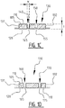
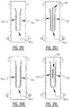
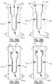
- First, second, third and fourth channel 140, 150, 160, 170 each have a bottom which forms the attachment zone 145, 155, 165, 175, see figurer 1C and figure 1D .
- top core wrap sheet 110 is attached to back core wrap sheet 120.
- the width w of the bottom, seen in a transverse direction of absorbent core 130, is preferably larger than 2 mm, more preferably larger than 3 mm and even more preferable larger than 4 mm.
- top core wrap sheet 110 and the back core wrap sheet 120 may be an attachment extending over a transverse distance which is at least 2 mm, preferably at least 3 mm, more preferably at least 4 mm; and/or the attachment may be a discontinuous attachment in a plurality of locations at a distance of each other, seen in a transverse direction of absorbent core 130.
- the attachment at the bottom between the top core wrap sheet and the back core wrap sheet is realized by any one of the following or a combination thereof: pressure bonding, thermobonding, sonic bonding, chemical bonding, adhesive, mechanical bonding.
- absorbent core 130 has a maximum thickness t.
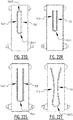
- each channel 140, 150, 160, 170 extends through at least 90 % of the maximum thickness of absorbent core 130, more preferably through 100% of the thickness of absorbent core 130, such that, in the channel 140, 150, 160, 170, substantially no absorbent material is present that between top core wrap sheet 110 and back core wrap sheet 120.
- the channel 140, 150, 160, 170 may be located below and/or above the attachment zones 145, 155, 165, 175, as will be explained in more detail below with reference to figure 14 .
- the attachment 145, 155, 165, 175 between top core wrap sheet 110 and back core wrap sheet 120, here at a bottom of each channel 140, 150, 160, 170, is a semi-permanent attachment configured to release after having been in contact with urine for a predetermined period of time, wherein said predetermined period of time is preferably smaller than 30 s.
- the attachment 145, 155, 165, 175 between top core wrap sheet 110 and back core wrap sheet 120, here at the bottom of each channel 140, 150, 160, 170 is a permanent attachment; and absorbent core 130 is configured such that, in a wetted state of absorbent core 130, the absorbent material extends over bottom 145, 155, 165, 175 of channel 140, 150, 160, 170.
- first and second channels 140, 150 Channels 140, 150, 160, 170 guide urine U or any other aqueous liquid through the side walls of channels 140, 150, 160, 170 into absorbent core 130.
- attachment zones may be provided by means of continuous attachments in the transversal direction of the absorbent core and/or continuous attachments in the longitudinal direction of the absorbent core and/or discontinuous attachments in the transversal direction of the absorbent core and/or discontinuous attachments in the longitudinal direction of the absorbent core.
- Absorbent core 130 has a front portion 130a extending at one side of a transverse crotch line which corresponds in this embodiment with fold line L, and a rear portion 130b extending at the other side of the transverse crotch line L.
- First and second channel 140, 150 extend at least in front portion 130a of absorbent core 130
- third and fourth channel 160, 170 extend at least in rear portion 130b of the absorbent core 130.
- the distance d12 between first and second channel 140, 150 in front portion 130a is smaller than the distance d34 between third and fourth channel 160, 170 in rear portion 130b.
- the plurality of channels 140, 150, 160, 170 together cover at least 60%, preferably at least 70% of the length la of absorbent core 130; indeed, in the embodiment of figure 1A-1D the channels cover a length equal to 11+13 which is more than 60% of the length la of absorbent core 130.
- the plurality of channels 140, 150, 160, 170 may be indicated with a color and/or with a pattern which is different from the color and/or pattern of topsheet. More in particular the area of the channels may comprise a print allowing a user to visually distinguish the channels.
- This print may be arranged on the topsheet, on the top core wrap sheet, on the back core wrap sheet, on the backsheet, or on any sheet in between the topsheet and the backsheet, as long as it is visible for a user.
- the sheets may be partially transparent, the print may be arranged on a sheet in between the topsheet and the backsheet, as long as it is visible through the topsheet and/or the backsheet. Preferably the print is visible when looking at the topsheet of the diaper.
- a topsheet area above first and second channels 140, 150 may be printed with an ink of a first color and a topsheet area above third and fourth channels 160, 170 may be printed with the same color or with a different color.
- a user will be able to easily recognize the front and rear portion of a diaper, and will recognize more easily how to put on the diaper.
- the chassis of the diaper 100 in figures 1A-1D comprises a liquid pervious topsheet (not shown in figures 1C and 1D , but the topsheet is a layer above top core wrap sheet 110) and liquid impervious backsheet (not shown in figures 1C and 1D , but the backsheet is a layer below back core wrap sheet 110).
- the topsheet may be attached to the top core wrap sheet 110, e.g. in the attachment zones 140, 150, 160, 170.
- the backsheet may be attached to the back core wrap sheet 120, e.g. in the attachment zones 140, 150, 160, 170.
- the chassis further includes side panels or ears 210, elasticized leg cuffs 230 and elastic waist elements (not shown).
- a front end portion of diaper 100 is configured as a front waist region 100a.
- the opposite rear end portion is configured as a back waist region 100b of diaper 100.
- An intermediate portion of diaper 100 is configured as crotch region CR, which extends longitudinally between first and second waist regions 100a and 100b.
- Waist regions 100a and 100b may include elastic waist elements such that they gather about the waist of the wearer to provide improved fit and containment.
- Crotch region CR is that portion of diaper 100 which, when the diaper 100 is worn, is generally positioned between the wearer's legs.
- the periphery of diaper 100 is defined by the outer edges of the diaper 100 in which longitudinal edges 101, 102 run generally parallel to a longitudinal axis of diaper 100 and transverse end edges 103, 104 run between the longitudinal edges 101, 102 generally parallel to a transverse axis of diaper 100.
- the chassis also comprises a fastening system, which may include at least one fastening or securing member 212 and at least one landing zone 220.
- the various components within diaper 100 may be bound, joined or secured by any method known in the art, for example by adhesives in uniform continuous layers, patterned layers or arrays of separate lines, spirals or spots.
- Top core wrap sheet, topsheet, back core wrap sheet, backsheet, absorbent material and other components may be assembled in a variety of well-known configurations and are well known in the art.
- Backsheet covers absorbent core 130 and preferably extends beyond the absorbent core 130 toward longitudinal edges 101, 102 and end edges 103, 104 of diaper 100 and may be joined with top sheet.
- Backsheet prevents bodily exudates absorbed by the absorbent core 130 and contained within diaper 100 from soiling other external articles that may contact the wearer, such as bed sheets and undergarments.
- backsheet is substantially impervious to bodily exudates and comprises a laminate of a nonwoven and a thin plastic film such as a thermoplastic film.
- Backsheet may comprise breathable materials that permit vapor to escape from diaper 100 while still preventing bodily exudates from passing through backsheet. It may be semi-rigid, non-elastic and can be made fully or partially elasticized and include backing.
- top sheet which is located above the top core wrap sheet 110, is preferably soft, exhibits good strikethroughs and has a reduced tendency to rewet from the liquid absorbent material.
- Top sheet may be semi-rigid and non-elastic, or may be fully or partially elasticized.
- Topsheet is intended to be placed in close proximity to the skin of the wearer when diaper 100 is worn. Topsheet permits bodily exudates to rapidly penetrate it so as to flow more quickly toward absorbent core 130 via a top surface thereof and via the plurality of channels 140, 150, 160, 170, preferably not allowing such bodily exudates to flow back through topsheet.
- Topsheet may be constructed from any one of a wide range of liquid and vapor permeable, preferably hydrophilic, materials.
- topsheet may be treated differently.
- Topsheet may include e.g. a surfactant on the upper surface so as to facilitate liquid transfer there through, especially at a central zone or area of topsheet located over absorbent core 130, and/or a hydrophobic agent on the lower surface to minimize the liquid contained within absorbent core 130 from contact wetting topsheet thereby reducing rewet values.
- Topsheet may be coated with a substance having rash preventing or rash reducing properties.
- topsheet covers substantially the entire wearer facing area of diaper 100, including substantially all of front waist region 100a, back waist region 100b, and crotch region CR.
- side panels 210, 210' and/or waist feature layers of the inner region may be formed from the same single topsheet material.
- topsheet may be formed from multiple different materials which vary across of topsheet. Such a multiple piece design allows for creation of preferred properties and different zones of the topsheet.
- Absorbent core 130 may comprise any absorbent material that is generally compressible, conformable, non-irritating to the wearer's skin, and capable of absorbing and retaining bodily exudates.
- Absorbent core 130 may comprise a wide variety of liquid absorbent materials commonly used in absorbent articles.
- absorbent core 130 comprises fluff material, typically cellulosic fluff pulp.
- absorbent core 130 may be substantially fluffless and comprise superabsorbent polymers.
- absorbent core 130 may comprise a combination of cellulosic fluff pulp and superabsorbent polymers.
- Absorbent core 130 may be configured to extend substantially the full length and/or width of diaper 100.
- absorbent structure 130 is not coextensive with the entire diaper 100 and is limited to certain regions of diaper 100 including crotch region CR.
- the absorbent core 300 extends to the edges of diaper 100 but the absorbent material is concentrated in the crotch region CR or another target zone of the diaper 100.
- absorbent core 130 is shown as having a substantially rectangular configuration, however, absorbent core 130 may be shaped differently, such as, elliptical, dogbane shaped, T-shaped or I-shaped. More in particular the width of the front portion 130a may be smaller than the width of the rear portion 130b of the absorbent core.
- absorbent core 130 examples of commonly occurring absorbent materials used for absorbent core 130 are cellulosic fluff pulp, tissue layers, highly absorbent polymers (so called superabsorbents), absorbent foam materials, absorbent nonwoven materials or the like. It is common to combine cellulosic fluff pulp with superabsorbent polymers in an absorbent core.
- Superabsorbent polymers are water-swellable, water-insoluble organic or inorganic materials capable of absorbing at least about 20 times its weight and in an aqueous solution containing 0.9 weight percent of sodium chloride.
- Diaper 100 may also utilize a pair of containment walls or cuffs 230.
- Each cuff 230 is a longitudinally extending wall structure preferably positioned on each side of absorbent core 130 and spaced laterally from the center line CL.
- cuffs 230 are attached, for example, by adhesive or sonic bonding to the lower structure.
- cuffs 230 are equipped with elastic members. When released or otherwise allowed relaxing, the elastic members retract inwardly. When diaper 100 is worn, the elastic members function to contract cuffs 230 about the buttocks and the thighs of the wearer in a manner, which forms a seal between diaper 100, the buttocks and the thighs.
- the waist regions 100a and 100b each comprise a central region and a pair of side panels or ears 210, 210' which typically comprise the outer lateral portions of the waist regions.
- These side panels 210, 210' may be unitary with the chassis or may be attached or joined thereto by any means know in the art.
- the side panels 210 positioned in the back waist region 100b are flexible, extensible and/or elastic in at least the lateral direction.
- the side panels 210 are non-elastic, semi-rigid, rigid and/or stiff.
- at least a portion of the back waist region 100b is attached by fastening or securing members 212 to at least a portion of the front waist region 100a.
- the fastening or securing members 212 may be e.g. adhesive, mechanical fasteners, hook and loop features, conceivable strings and/or combinations thereof.
- the fastening or securing members 212 may also be co-adhesive such that they adhere to each other but not other materials.
- the materials making up the fastening or securing members 212 are flexible, extensible and/or elastic, allowing them to better conform to the shape and movements of the body and thus, to reduce the likelihood that the fastening system will irritate or injure the wearer's skin.
- the absorbent article may be pants and the like. In this configuration, the absorbent article may or may not have fastening members.
- Diaper 100 may also employ additional layers, such as an acquisition layer and/or dispersion layer situated between topsheet and absorbent core 130, and/or coverstock layers, and/or other layers situated between absorbent core 130 and backsheet.
- An acquisition layer and/or dispersion layer serves to slow down the flow so that the liquid has adequate time to be absorbed by absorbent core 130.
- Figure 9A and 9B show an acquisition layer 190 above top core wrap layer 110.
- Diaper 100 may also include such other features, components and elements as are known in the art including waistbands, waist cap features, elastics and the like to provide better fit, containment and aesthetic characteristics. These features may be assembled in a variety of well-known configurations and are well known in the art.
- FIGS 2A and 2B illustrate another exemplary embodiment of a diaper 100.
- Diaper 100 comprises a liquid pervious topsheet, a liquid impervious backsheet, and an absorbent core 130 positioned in between topsheet and backsheet.
- Absorbent core 130 has a first and second longitudinal edge 131, 132 and a first and second transverse edge 133, 134.
- Absorbent article 100 is provided at the top core wrap sheet 110 with a first and a second attachment zone 145, 155 for creating a first and second channel 140, 150 located a distance d12 of each other.
- First and second channel 140, 150 each extend from a crotch region CR in the direction of the first transverse edge 133 and the second transverse edge 134.
- first and second channel extend over more than 80% of the length of absorbent core 130.
- the distance d12 is between 10 mm and 50 mm, more preferably between 15 and 30 mm.
- the length of the first and second channel is substantially the same, more preferably the length 11 of the first channel and the length 12 of the second channel is between 100 mm and 300 mm, more preferably between 100 mm and 250 mm.
- the distance between the first/second attachment zone 145, 155 and the transverse edge 133 is between 50 and 125 mm, more preferably between 75 and 115 mm, and the distance between the first/second attachment zone 145, 155 and the transverse edge 134 is between 50 and 125 mm, more preferably between 75 and 115 mm.
- First channel 140 and second channel 150 are substantially parallel and run in the longitudinal direction of absorbent core 130. However, it is also possible for first and second channel 140, 150 to extend under a small angle with respect to the longitudinal direction of absorbent core 130, e.g. an angle between 5 and 10°.
- first and second channel 140, 150 may be diverging slightly outwardly in the direction of first transverse edge 133 and may be diverging slightly outwardly in the direction of second transverse edge 134.
- first channel 140 and second channel 150 are arranged symmetrically with respect to a longitudinal center line CL of absorbent core 130.
- Absorbent article 100 is further provided with a third and a fourth channel 160, 170 located a distance d34 of each other.
- Third and fourth channel 160, 170 each extend from crotch region CR in the direction of first and second transverse edge 134.
- the distance d12 between first and second channel 140, 150 is different from the distance d34 between third and fourth channel 160, 170.
- the distance d34 is between 25 mm and 85 mm, more preferably between 35 mm and 55 mm.
- the length of the third and fourth channel 160, 170 is substantially the same, more preferably the length 13 of the third channel and the length 14 of the fourth channel is between 50 mm and 150 mm, more preferably between 60 mm and 140 mm.
- the distance between the third attachment zone 165 and the first longitudinal side 131 is between 10 and 30 mm
- the distance between the second attachment zone 175 and the second longitudinal side 132 is between 10 and 30 mm.
- Third channel 160 and fourth channel 170 are substantially parallel and run in the longitudinal direction of absorbent core 130. However, it is also possible for third and fourth channel 160, 170 to extend under a small angle with respect to the longitudinal direction of absorbent core 130, e.g. an angle between 5 and 10°.
- third and fourth channel 160, 170 may be diverging slightly outwardly in the direction of first transverse edge 133 and second transverse edge 134.
- Preferably third channel 160 and fourth channel 170 are arranged symmetrically with respect to a longitudinal center line CL of absorbent core 130.
- first, second, third and fourth channel 140, 150, 160, 170 each have a bottom 145, 155, 165, 175, similar to the bottom illustrated in figure 1C and figure 1D for the first embodiment of figures 1A-1D .
- top core wrap sheet 110 is attached to back core wrap sheet 120 as described previously.
- absorbent core 130 has a maximum thickness t.
- each channel 140, 150, 160, 170 extends through at least 90 % of the maximum thickness of absorbent core 130, more preferably through 100% of the thickness of absorbent core 130, such that, in the channel 140, 150, 160, 170, substantially no absorbent material is present that between top core wrap sheet 110 and back core wrap sheet 120.
- Absorbent core 130 has a front portion 130a extending at one side of a transverse crotch line T, and a rear portion 130b extending at the other side of the transverse crotch line T.
- First, second, third and fourth channel 140, 150, 160, 170 each extend both in front portion 130a and rear portion 130b of absorbent core 130.
- the distance d12 between first and second channel 140, 150 is smaller than the distance d34 between third and fourth channel 160, 170, and the length 11 of first and second channel 140, 150 is bigger than the length 13 of third and fourth channel 160, 170.
- Such a channel pattern has the advantage that liquid can be distributed over substantially the entire absorbent core 130, and that any leakage risks in various positions of the wearer can be reduced.
- the plurality of channels 140, 150, 160, 170 together cover at least 60%, preferably at least 70% of the length la of absorbent core 130; indeed, in the embodiment of figures 1A-1D the channels cover a length equal to 11 which is more than 70% of the length la of absorbent core 130.
- the plurality of channels 140, 150, 160, 170 may be indicated in a color and/or with a pattern which is different from the color and/or pattern of topsheet. More in particular the area of the channels may comprise a print allowing a user to visually distinguish the channels. For example, an area of the topsheet above front portions of channels 140, 150, 160, 170 may be printed with an ink of a first color and an area of the topsheet above rear portions the channels 140, 150, 160, 170 may be printed with a different color. In that manner a user will be able to easily recognize the front and rear portion of a diaper, and will recognize more easily how to put on the diaper.
- Topsheet, backsheet and absorbent core 130 may have the same features as described above in connection with figures 1A-1D .
- Figure 3 illustrates a variant of diaper 100 of figures 1A-1D .
- the features and characteristics are similar with this difference that a fifth channel 180 is provided in top core wrap sheet 110, in between third and fourth channel 160, 170 and extending along a longitudinal center line of diaper 100.
- the first and second channels are slightly longer and extend over transverse fold line L in the direction of second transverse edge 134.
- the third and fourth channel are slightly shorter compared to the embodiment of figures 1A-1D .
- Figure 4 illustrates a further variant of diaper 100 of figures 1A-1D .
- the features and characteristics are similar with this difference that the first and second channels are slightly longer and extend over transverse fold line L in the direction of second transverse edge 134, in between third and fourth channel 160, 170.
- the distribution of the liquid and the creation of the cup/tub shape can be further improved by this additional length.
- Figure 5 illustrates a variant of diaper 100 of figure 4 .
- first channel 140 is connected to third channel 160 through a first transverse channel portion 147 and that second channel 150 is connected to fourth channel 170 through a second transverse channel portion 157.
- any liquid can flow from the first channel 140 to the third channel 160 and vice versa, and liquid can flow from the second channel 150 to the fourth channel 170 and vice versa, resulting in an even better distribution of the liquid.
- channel portions 147, 157 may help in creating the tub shape upon wetting of the absorbent core 130.
- first and second channel 140, 150 extend in a longitudinal direction of absorbent core 130 over a length which is longer than the length of third and fourth channel 160, 170, wherein third and fourth channel extend between crotch region CR and second transverse edge 134 and first and second channel extend between crotch region CR and first transverse edge 133.
- Figure 6 illustrates another more basic exemplary embodiment of a diaper 100.
- Diaper 100 comprises a liquid pervious topsheet, a liquid impervious backsheet, and an absorbent core 130 positioned in between topsheet and backsheet.
- Absorbent core 130 has a first and second longitudinal edge 131, 132 and a first and second transverse edge 133, 134.
- Absorbent article 100 is provided with a first and a second attachment zone for creating a first and a second channel 140, 150 located a distance d12 of each other, upon wetting of the diaper 100.
- First and second channel 140, 150 each extend from a crotch region CR in the direction of the first transverse edge 133 and the second transverse edge 134.
- first and second channel extend over more than 80% of the length of absorbent core 130.
- the distance d12 is between 10 mm and 90 mm, more preferably between 20 mm and 80 mm, even more preferably between 30 mm and 50 mm.
- the length of the first and second channel is substantially the same, more preferably the length 11 of the first channel and the length 12 of the second channel is between 100 mm and 350 mm, more preferably between 150 mm and 300 mm.
- the distance between the first channel 140 and the first longitudinal side 131 is between 10 mm and 30 mm
- the distance between the second channel 150 and the second longitudinal side 132 is between 10 mm and 30 mm.
- the distance between the first/second channel 140, 150 and the transverse edges 133, 134 is between 20 mm and 100 mm, more preferably between 30 mm and 75 mm.
- First channel 140 and second channel 150 are substantially parallel and run in the longitudinal direction of absorbent core 130. However, it is also possible for first and second channel 140, 150 to extend under a small angle with respect to the longitudinal direction of absorbent core 130, e.g. an angle between 5 and 10°.
- first and second channel 140, 150 may be diverging slightly outwardly in the direction of first transverse edge 133 and may be diverging slightly outwardly in the direction of second transverse edge 134.
- first channel 140 and second channel 150 are arranged symmetrically with respect to a longitudinal center line CL of absorbent core 130.
- First and second channel 140, 150 may each have a bottom 145, 155, similar to the bottom illustrated in figurer 1C for the first embodiment of figures 1A-1D . However, it is noted that the channels 140, 150, 160, 170 may be located below and/or above the attachment zones 145, 155, 165, 175, as will be explained in more detail below with reference to figure 14 .
- top core wrap sheet 110 is attached to back core wrap sheet 120 as described previously.
- absorbent core 130 has a maximum thickness t.
- each channel 140, 150, 160, 170 extends through at least 90 % of the maximum thickness of absorbent core 130, more preferably through 100% of the thickness of absorbent core 130, such that, in the channel 140, 150, 160, 170, substantially no absorbent material is present between top core wrap sheet 110 and back core wrap sheet 120.
- the areas of the channels 140 and/or 150 and/or 160 and/or 170 may be indicated in a color and/or with a pattern which is different from the color and/or pattern of topsheet. More in particular the area of the channels may comprise a print allowing a user to visually distinguish the channels. This print may be arranged on the topsheet, on the top core wrap sheet, on the back core wrap sheet, on the backsheet, or on any sheet in between the topsheet and the backsheet, as long as it is visible for a user. Preferably the print is visible when looking at the topsheet of the diaper.
- a front portion of the channel 140 and/or 150 and/or 160 and/or 170 may be indicated with an ink of a first color and a rear portion the channels 140 and/or 150 and/or 160 and/or 170 may be indicated with a different color.
- a user will be able to easily recognize the front and rear portion of a diaper. Indeed, the user will know that the first color has to be on the left and the second color on the right. Hence he will recognize more easily how to put on the diaper.
- Topsheet, backsheet and absorbent core 130 may have the same features as described above in connection with figures 1A-1D .
- Figures 7 and 8 illustrate baby pants variants of the baby diaper embodiments of figures 1A and 2A .
- the side panels 210, 210' are larger compared to the embodiments of figures 1A and 2A . It is clear to the skilled person that any embodiment described in view of baby diapers, is applicable in a similar manner to baby pants, mutatis mutandis.
- Figure 10 illustrates an embodiment of a method for manufacturing an absorbent article according to the invention.
- the method comprises in a first step guiding a first sheet material 110 along an optional guide roller 5, and further along a rotating member 10, wherein a surface 15 of said rotating member 10 is provided with a pattern with suction zones 13, 13' and non-suction zones 11, 12; 11', 12'.
- the first sheet material 110 is shown in a transparent manner to reveal the suction and non-suction zones of the rotating member 10.
- the suction zones 13, 13' may be provided with holes, and the non-suction zones 11, 12; 11', 12' are formed of closed material.
- the non-suction zones 11, 12; 11', 12' may be provided with inserts as shown in figure 10A .
- the inserts 11, 12; 11', 12' may have a trapezoidal cross section.
- Figure 10B shows an insert pattern with four non-suction zones 11a, 11b, 12a, 12b per absorbent core.
- the inserts may be fixed e.g. with screws on the rotating member 10.
- a vacuum is applied, see VACUUM 1.
- the non-suction zones 11, 12; 11', 12' comprise at least a first elongate zone 11, 11' and a second elongate zone 12, 12' extending in a circumferential direction of the rotating member 10.
- an absorbent material F is applied via a hopper 40 on said first sheet material 110 on the rotating member 10 such that the suction zones 13, 13' are covered with absorbent material and substantially no absorbent material is present on the non-suction zones 11, 12; 11', 12'.
- a second sheet material 120 is applied on top of the absorbent material on the first sheet material 110, e.g. using a further rotating member 20. This is shown also in figure 10C where a cross section through the absorbent core is shown during the application of the second sheet material 120.
- Figure 10D shows the cross section of the absorbent core downstream of rotating member 10.
- One of said first and second sheet material is a top core wrap sheet material, and the other one is a back core wrap sheet material.
- the first sheet material 110 is the top core wrap sheet material.
- the first sheet material 110 is attached to the second sheet material 120 at least in the areas where substantially no absorbent material is present, and such that at least a first and a second channel 140, 150 are formed in said top core wrap sheet material 110.
- the attaching may be done by applying pressure and heat on the top core wrap sheet material 110 and/or on the back core wrap sheet material 120 in the areas where substantially no absorbent material is present, e.g.
- a rotating member 30 and/or opposite rotating member 30' which is provided with at least a first and a second seal rib 31, 32 dimensioned for applying pressure and heat on the top core wrap sheet material 110 in the areas where substantially no absorbent material is present in order to create the first and second channel 140, 150, respectively.
- top core wrap sheet and the back core wrap sheet may not be sufficiently strongly attached to one another, especially in cases where a significant amount of liquid is absorbed. Therefore, it may be desirable to additionally use a binder, such as glue, to strengthen the bond between the top and back core wrap sheets.
- a binder such as glue
- a binder such as glue
- the first sheet material 110 is being guided along an optional guide roller and further along a rotating member a binder, such as glue, may first be applied to the first sheet material, but only in substantially parallel stripes which do not overlap with the intended locations of the attachment zones 140, 150, 160, 170.
- the first sheet material forms the bottom core wrap, but in other embodiments this can also be the top core wrap.
- the skilled person will be aware of various method of binder/glue application, such as spraying, contact application and so on.
- Fig. 10E shows a possible pattern for the application of glue to the first sheet material, which will be the back core wrap.
- there are three stripes 111, 111', 111" but a different number of substantially parallel stripes, either continuous, intermittent and/or discontinuous in the longitudinal direction, may also be chosen depending on the shape and locations of the attachment zones 140, 150, 160, 170, which preferably cover a substantial portion of the surface of the bottom core wrap while not overlapping with the intended location of the attachment zones, and preferably while keeping some distance from the intended location of the attachment zones.
- Fig. 10E illustrates an application pattern of stripes, it is clear to the skilled person that the application pattern can be adapted and tuned depending on the intended shape, configuration and location of the one or more attachment zones.
- the skilled person will know how to best adapt the binder application zones on the first and second sheet materials 110, 120 for other configurations of attachments zones, such as the ones described in the present application.
- the application of the glue to the bottom core wrap takes place while the bottom core wrap is moved towards the rotating number, and before the absorbent material is added to it.
- the sheet material on the rotating member is already provided with binder, and may subsequently have absorbent material attached thereto via the hopper.
- Figure 10F shows application of glue to the second sheet material 120, which in this case will become the top core wrap.
- the application of the binder preferably happens along substantially parallel stripes 121, 121', which preferably are complementary to the stripes on the first sheet material 110.
- the application of glue to the top core wrap sheet happens at a distance from hopper 40, to minimize the chance of contamination, i.e. absorbent material sticking to the areas that are to become attachment zones 140, 150, 160, 170.
- the binder may be applied before or while the sheet material is guided along further rotating member 20.
- the dotted lines merely indicate the intended position of the attachment zones 140, 150, 160, 170; they do not indicate any interruption or change in the binder application.
- the skilled person will be aware of various method of binder/glue application, such as spraying, contact application and so on.
- Figure 10G shows the result after the third step described above has taken place, i.e. after the second sheet material 120, which here is the top core wrap sheet, is applied on top of the absorbent material on the first sheet material 110, e.g. using a further rotating member 20.
- the pattern fill indicates the presence of binder, and not the presence of absorbent material, since the absorbent material will not be present in the areas indicated by the dotted lines.
- These areas will be bonded together in a fourth step such as described above, such that channels 140, 150, 160 and 170 are formed in said back core wrap sheet materials 110 and/or 120, for instance by applying pressure and heat on the back core wrap sheet material 110 and/or on the top core wrap sheet material 120 in the areas where substantially no absorbent material is present, e.g.
- a rotating member 30 and/or opposite rotating member 30' which is provided with at least a first and a second seal rib 31, 32 dimensioned for applying pressure and heat in between the core wrap sheet materials 110 and 120 in the areas where substantially no absorbent material is present in order to create the channels 140, 150, 160 and 170.
- figure 10H shows the absorbent article resulting from the above-described method, in which a further step has taken place of traversal sealing in bands 122, 122' by chemical, thermal or physical binding such as for in stance glue, heat and/or pressure, which prevents the core from opening up and the front and the back. Note that this step of transversal sealing may also take place prior to the fourth step.
- the above-described method may yield an absorbent article with higher dry and especially wet integrity and which avoids unwanted migration of absorbent material, while avoiding the risk of contamination in the attachment zones 140, 150, 160 and 170 which may impede the formation of channels.
- this method is not limited to this particular configuration of attachment zones and will know how to best adapt the binder application zones on the first and second sheet materials 110, 120 for other configurations, such as the ones described in the present application. More in particular the skilled person understands that the method is also useful for absorbent cores with only one attachment zone or with more than two attachment zones.
- Figure 11A illustrates an exemplary embodiment of an absorbent core 130 with four attachment zones creating channels 140, 150, 160, 170.
- the attachment zones are formed by welding the top core wrap sheet 110 to the back core wrap sheet 112. This welding may be done according to a predetermined sealing pattern.
- the pattern consists of a plurality of discrete shapes 143, here a plurality of squares.
- the discrete shapes 143 have dimensions smaller than 2 mm.
- the distance between adjacent discrete shapes is between 0.5 and 3 mm.
- Figure 11B illustrates another exemplary embodiment of a sealing pattern that may be used in an embodiment of the invention.
- the pattern consists of a plurality of discrete shapes in the form of rounded elements 143.
- the rounded elements may have a length dimension between 0.5 mm and 5 mm, and a width dimension between 0.5 mm and 5 mm.
- the discrete shapes are equally distributed in the attachment zones.
- Figure 11C illustrates yet another embodiment where the sealing pattern consists of discrete shapes which are rounded.
- the sealing pattern consists of discrete shapes which are rounded.
- three columns of rounded discrete elements 143 are used for each attachment zone 140, 150, 160, 170.
- Figure 11D illustrates another exemplary embodiment of an attachment zone for creating a channel 140, 150, 160, 170.
- the attachment zone is formed by a plurality of continuous line-shaped attachments 140a, 140b, 140c.
- the number of lines used may vary, and may be e.g. two lines or more than three adjacent lines.
- the distance w between a first line 140a and a last line 140c is at least 1 mm, more preferably at least 2 mm, even more preferably more than 4 mm.
- the attachment zones creating channels 140, 150, 160, 170 may be formed of a plurality of discrete elements 143, wherein each discrete element has a width w which covers the entire width w of the attachment zone.
- Figure 13A illustrates an exemplary embodiment of a traditional absorbent core.
- a traditional absorbent core absorbs liquid
- the core becomes bulky such that the diaper is no longer well adapted to the body.
- the liquid does not spread evenly but remains in the center of the absorbent core.
- Figure 13B illustrates an exemplary embodiment of an absorbent core manufactured according to the invention. Thanks to the attachment zones and associated channels 140, 150, 160, 170, the liquid is evenly spread, resulting in the formation of tubes 301, 302, 303 which provide a tub shape to the absorbent core 130. Such a tub shape adapts perfectly to the body. Further, compared to prior art solutions, the liquid is kept in an improved manner absorbed in the absorbent core 130, and the risk on leakage is reduced.
- Figure 12 shows a perspective view of a diaper in the wetted state.
- Figure 12 clearly illustrates the formation of three tubes 301, 302, 303 giving the diaper a tub shape which is well adapted to the body.
- Figure 14 illustrates an absorbent core 130 comprising an absorbent material 105 between a top core wrap sheet 110 and a back core wrap sheet 120.
- the absorbent core has a first and second longitudinal edge 131, 132.
- the absorbent core 130 is provided with a plurality of attachment zones 145.
- Figure 14 illustrates that the attachment zones 145 may be positioned at different locations. As illustrated on the left in figure 14 , the attachment zone may be positioned more or less centrally such that an upper channel portion 140a and a lower channel portion 140b is formed. In an alternative embodiment, the attachment zone 145 may be positioned at the bottom such that an upper channel 140 is created, see the example in the middle of figure 14 .
- the attachment zone 145 may be located at the top, such that the channel 140 is formed below top core wrap sheet 110.
- the attachment zones allow the formation of channels upon wetting of the absorbent core 130.
- the method is illustrated for two channels, the skilled person understands that the method can be adapted for forming three, four or more channels, and in particular for manufacturing any one of the absorbent articles disclosed in the present application.
- Figures 15A-15X , 16A-16S , 17A-17V and 18A-F illustrate multiple advantageous positions for the attachment zones in an absorbent core manufactured according to the invention.
- the plurality of attachment zones comprises a first attachment zone 140, a second attachment zone 150, a third attachment zone 160 and a fourth attachment zone 170, and a central attachment zone 180.
- the first and second attachment zones 140 diverge from the central attachment zone 180 in the crotch region in the direction of a rear transverse edge of absorbent core.
- the third and fourth attachment zone 160, 170 diverge from the central attachment zone 180 in the crotch region in the direction of a front transverse edge of absorbent core.
- the plurality of attachment zones comprises a first attachment zone 140, a second attachment zone 150, a third attachment zone 160 and a fourth attachment zone 170.
- This embodiment is similar to the embodiment of figure 2A-2B , with this difference that the outer attachment zones 160, 170 are longer than the inner attachment zones 140, 150.
- the plurality of attachment zones comprises a first attachment zone 140, a second attachment zone 150, a third attachment zone 160 and a fourth attachment zone 170, and a central attachment zone 180.
- the first and third attachment zones 140, 160 are aligned in the longitudinal direction.
- the second and fourth attachment zones 150, 170 are aligned and extend substantially parallel to the first and third attachment zones 140, 160.
- the plurality of attachment zones comprises a first attachment zone 140 and a second attachment zone 150.
- the first and second attachment zones 140 are substantially parallel in the crotch region and diverge in the direction of a front transverse edge of absorbent core.
- the plurality of attachment zones comprises a first attachment zone 140 and a second attachment zone 150.
- the first and second attachment zones 140 partially overlap in the crotch region and diverge in the direction of a front transverse edge of absorbent core.
- the plurality of attachment zones comprises a first longitudinal attachment zone 140 and a second longitudinal attachment zone 150 which are interconnected by an attachment portion 1045 in a front part of the absorbent core. In that manner any leakage via the front part can be reduced or avoided.
- the plurality of attachment zones comprises a first longitudinal attachment zone 140, a second longitudinal attachment zone 150, and a transverse attachment zone 1045 in a front part of the absorbent core.
- the transverse attachment zone 1045 substantially connects a front end of first longitudinal attachment zone 140 and a front end of second longitudinal attachment zone 150
- the plurality of attachment zones comprises a first longitudinal attachment zone 140, a second longitudinal attachment zone 150, a central longitudinal attachment zone 180.
- the first and second longitudinal attachment zones 140, 150 extend adjacent to each other from the crotch region to a rear transverse edge of the absorbent core.
- the central longitudinal attachment zone 180 extends from the crotch region in the direction of the front transverse edge of the absorbent core.
- the exemplary embodiment of figure 15I is similar to the embodiment of figure 15H , with this difference that the central attachment zone 180 extends also from the crotch region in the direction of the rear transverse edge, partially in between the first and second attachment zone 140, 150.
- the plurality of attachment zones comprises a first longitudinal attachment zone 140 and a second longitudinal attachment zone 150 which are interconnected by an attachment portion 1045 in a front part of the absorbent core and an attachment portion 1045' in a rear part of the absorbent core. In that manner any leakage via the front and rear part can be reduced or avoided.
- the plurality of attachment zones comprises a first attachment zone 140, a second attachment zone 150, a third attachment zone 160 and a fourth attachment zone 170, and a central attachment zone 180.
- the first and second attachment zones 140, 150 extend adjacent to each other from a crotch region in the direction the front transverse edge.
- the third and fourth attachment zones 160, 170, as well as the central attachment zone extend adjacent to each other from a crotch region in the direction the rear transverse edge. In that manner the distribution of liquid in the rear part of the absorbent core can be further enhanced.
- the plurality of attachment zones comprises a first longitudinal attachment zone 140, a second longitudinal attachment zone 150, and a central longitudinal attachment zone 180.
- the first and second longitudinal attachment zones 140, 150 extend adjacent to each other over at least 60% of the length of the absorbent core.
- the central longitudinal attachment zone 180 extends between the first and second attachment zones 140, 150, from the crotch region in the direction of the rear transverse edge of the absorbent core.
- the plurality of attachment zones comprises a first longitudinal attachment zone 140, a second longitudinal attachment zone 150, a central rear longitudinal attachment zone 180a, and a central front longitudinal attachment zone 180b.
- the first and second longitudinal attachment zones 140, 150 extend adjacent to each other over at least 60% of the length of the absorbent core.
- the central rear and front longitudinal attachment zones 180a, 180b extends between the first and second attachment zones 140, 150, in a rear and front part of the absorbent core, respectively.
- the plurality of attachment zones comprises a first attachment zone 140, a second attachment zone 150, and a central attachment zone 180.
- the first and second attachment zones 140 diverge from the crotch region in the direction of a front and rear transverse edge of absorbent core.
- the central attachment zone is provided in between the first and second attachment zone 140, 150, mainly in a front portion of the absorbent core.
- the plurality of attachment zones comprises a first longitudinal attachment zone 140, a second longitudinal attachment zone 150, and a central longitudinal attachment zone 180.
- the first and second longitudinal attachment zones 140, 150 extend adjacent and parallel to each other in the crotch region.
- the central longitudinal attachment zone 180 extends between the first and second attachment zones 140, 150, over at least 60% of the length of the absorbent core.
- the plurality of attachment zones comprises a first attachment zone 140 and a second attachment zone 150.
- the first and second attachment zones 140, 150 extend from the crotch region in the direction of a front and rear transverse edge of absorbent core, and are curved such that the first and second attachment zones 140, 150 cross each other at a first crossing point in a front part of the absorbent core and in a second crossing point in the rear part of the absorbent core.
- the plurality of attachment zones comprises a first longitudinal attachment zone 140, a second longitudinal attachment zone 150, a third attachment longitudinal zone 160 and a fourth longitudinal attachment zone 170.
- the first and second attachment zones 140, 150 extend from the crotch region in the direction of the rear transverse edge, and are interconnected via transverse attachment portions 147, 157 to third and fourth attachment zone 160, 170 extending from the crotch region to the front transverse edge, respectively.
- the exemplary embodiment of figure 15R is similar to the embodiment of figure 15G with this difference that two parallel transverse attachment zones 1045a and 1045b are provided in the front region of the absorbent core.
- the plurality of attachment zones comprises a first attachment zone 140, a second attachment zone 150, a third attachment zone 160 and a fourth attachment zone 170.
- the first and second attachment zones 140, 150 diverge from the crotch region in the direction of a front and rear transverse edge of absorbent core.
- the third and fourth attachment zones 160, 170 are located outwardly of the first and second attachment zones 140, 150, are shorter than the first and second attachment zones 140, 150, and also diverge from the crotch region in the direction of a front and rear transverse edge of absorbent core.
- a plurality of tubes is created, wherein the tubes are smaller in a center of the crotch region and gradually widen in the direction of the front and rear transverse edge of the absorbent core.
- the shape of the tub which is formed in the wetted state can be further improved to fit well to the body.
- the plurality of attachment zones comprises a first longitudinal attachment zone 140 and a second longitudinal attachment zone 150, wherein front end portions 140', 150' thereof diverge in the direction of the front transverse edge of the absorbent core.
- the plurality of attachment zones comprises a first longitudinal attachment zone 140, a second longitudinal attachment zone 150, a third longitudinal attachment zone 160 and a fourth longitudinal attachment zone 170, and a central longitudinal attachment zone 180.
- the first and second attachment zones 140, 150, as well as the central attachment zone 180 extend adjacent to each other from a crotch region in the direction the front transverse edge.
- the third and fourth attachment zones 160, 170 extend adjacent to each other from a crotch region in the direction the rear transverse edge. In that manner the distribution of liquid in the front part of the absorbent core can be further enhanced.
- the plurality of attachment zones comprises a first longitudinal attachment zone 140, a second longitudinal attachment zone 150, and a central longitudinal attachment zone 180.
- the first and second attachment zones 140, 150 extend adjacent to each other from a crotch region in the direction the front transverse edge.
- the central attachment zone 180 extends from a crotch region in the direction the rear transverse edge.
- the exemplary embodiment of figure 15W is similar to the embodiment of figure 15V with this difference that the central attachment zone 180 extends partially in between the first and the second attachment zone 140, 150.
- the exemplary embodiment of figure 15X is similar to the embodiment of figure 15V with this difference that the central attachment zone 180 extends all the way in between the first and the second attachment zone 140, 150 in the direction of the front transverse edge.
- the plurality of attachment zones comprises a first attachment zone 140 and a second attachment zone 150.
- the first and second attachment zones 140 are substantially parallel in a rear part of the crotch region, whilst the transverse distance between the first and second attachment zones gradually increases in the direction of a front transverse edge of absorbent core.
- the plurality of attachment zones comprises a first attachment zone 140 and a second attachment zone 150.
- the first and second attachment zones 140 partially overlap in a rear part of the crotch region, whilst the transverse distance between the first and second attachment zones gradually increases in the direction of a front transverse edge of absorbent core.
- the plurality of attachment zones comprises a first longitudinal attachment zone 140, a second longitudinal attachment zone 150, a third attachment longitudinal zone 160 and a fourth longitudinal attachment zone 170.
- the first and second attachment zones 140, 150 extend from the crotch region in the direction of the rear transverse edge, and are interconnected via transverse attachment portions 147, 157 to third and fourth attachment zone 160, 170 extending from the crotch region to the front transverse edge, respectively.
- the distance between the first and second attachment zones is smaller than the distance between the third and fourth attachment zones
- the distance between the first and second attachment zones is bigger than the distance between the third and fourth attachment zones.
- the embodiment of figure 16E is similar to the embodiment of figure 16D with this difference that the third and fourth attachment zones overlap in a front portion of the absorbent core.
- FIG 16F is similar to the embodiment of figure 15U with this difference that the third and fourth longitudinal attachment zones 160, 170 are interconnected at their rear end by a transverse attachment zone 1045.
- the embodiment of figure 16G is similar to the embodiment of figure 15B with this difference that the third and fourth longitudinal attachment zones 160, 170 have end portions which diverge outwardly in the direction of the front transverse edge and the rear transverse edge of the absorbent core.
- the embodiment of figure 16H is similar to the embodiment of figure 15O with this difference that the first and second attachment zones 140, 150 have end portions which diverge outwardly in the direction of the front transverse edge and the rear transverse edge of the absorbent core.
- the embodiment of figure 16I is similar to the embodiment of figure 15C with this difference that the first, second, third and fourth attachment zones 140, 150, 160, 170 are shorter such that in a central part of the crotch region only central attachment zone 180 is present.
- the embodiment of figure 16J is similar to the embodiment of figure 16I with this difference that the two central attachment zones 180 are provided between first and third attachment zones 140, 160 and second and fourth attachment zones 150, 170.
- the plurality of attachment zones comprises a first longitudinal attachment zone 140, a second longitudinal attachment zone 150, a third attachment longitudinal zone 160 and a fourth longitudinal attachment zone 170.
- the first and second attachment zones 140, 150 extend from the crotch region in the direction of the front transverse edge.
- the third and fourth attachment zone 160, 170 extend from the crotch region to the rear transverse edge.
- the distance between the first and second attachment zones 140, 150 is bigger than the distance between the third and fourth attachment zones 160, 170.
- the third and fourth attachment zones 160, 170 extend partially between the first and second attachment zones 140, 150, whilst in figure 16L , seen in the longitudinal direction, the third and fourth attachment zones 160, 170 are at a distance of the first and second attachment zones 140, 150.
- the plurality of attachment zones comprises a first longitudinal attachment zone 140, a second longitudinal attachment zone 150, and outwardly diverging attachment zones 160, 170 in a front portion of the absorbent core.
- a central attachment zone 180 is provided between the first longitudinal attachment zone 140 and the second longitudinal attachment zone 150.
- Figure 16P is similar to the embodiment of figure 16H with this difference that first and second attachment zones are provided more to the front of absorbent core.
- the plurality of attachment zones comprises a first longitudinal attachment zone 140 and a second longitudinal attachment zone 150 which extend over at least 60% of the length of the absorbent core.
- the first longitudinal attachment zone 140 and the second longitudinal attachment zone 150 are each provided at a front end and at a rear end with an outwardly directed transverse portion. In that manner leakage risks at the front and rear parts of the absorbent core can be further reduced.
- Figure 16R is similar to the embodiment of figure 15B .
- the plurality of attachment zones comprises a first undulated attachment zone 140 and a second undulated attachment zone 150 each extending over at least 60% of the length of the absorbent core.
- the undulations will increase the length of the channels 140, 150, further improving the liquid distribution in the absorbent core.
- FIGS 17A-17V and figures 18A-18G illustrate yet other exemplary embodiments of an absorbent core manufactured according to the invention.
- Figures 17A, 17B , 17H and 17K illustrate that the first and second attachment zones 140, 150 may comprise curved portions.
- Figures 17C, 17D , 17E, 17F , 17G , 17J , 17L , 17M, 17N, 17O, 17P , 17Q, 17R, 17S, 17T , 17U, 17V illustrate that various patterns are possible with one or more longitudinal sections 140, 150, 160, 170, 180, and/or one or more inclined sections 160, 170, 160a, 160b, 170a, 170b and/or one or more transverse sections 1045, 1045a, 1045b, 1045c.
- Figure 17I illustrates that also curved transverse sections 1045a, 1045b may be used.
- Figures 18A-18G illustrate further embodiments.
- the first to fourth attachment zones are similar to the first to fourth attachment zones of figure 16I , but instead of a central rectilinear attachment zone, there is provided an oval attachment zone 180 in the crotch region, between the first and second attachment zone 140, 150 and the third and fourth attachment zone 160, 170.
- Figures 18B, 18C, 18D illustrate that various patterns are possible with one or more longitudinal sections and/or one or more inclined sections and/or one or more transverse sections as described before.
- Figures 18E, 18F, 18G illustrate that the first and second attachment zones 140, 150 may comprise various rectilinear sections which are oriented at an angle with respect to the longitudinal direction of the absorbent core.
- Figures 19A-19D illustrate further embodiments wherein the absorbent core is provided with at least a first attachment zone 140, wherein in said first attachment zone 141 said top core wrap sheet is attached to said back core wrap sheet along an attachment which extends, seen in a transverse and/or longitudinal direction of the absorbent core, over a transverse and/or longitudinal distance which is at least 1 mm, preferably at least 2 mm, more preferably at least 3mm, most preferably at least 4mm; and/or said top core wrap sheet is attached to said back core wrap sheet along a discontinuous attachment at a plurality of locations at a distance of each other, seen in the transverse and/or longitudinal direction of the absorbent core; such that upon wetting of the absorbent material, a first channel is created at said first attachment zone 140.
- a single longitudinal attachment zone 140 is illustrated, along with a first and second transversal attachment zone 1045a, 1045b which are positioned at either end of the longitudinal attachment zone 140.
- the first and second transversal attachment zone 1045a, 1045b are illustrated as curved zones, but it is clear to the skilled person that the first and/or second transversal attachment zone may also be provided as straight zones.
- a single longitudinal attachment zone 140 is illustrated, along with a first and second transversal attachment zone 1045a, 1045b which are positioned between the attachment zone 140 and the first transversal edge of the absorbent core.
- first and second transversal attachment zones 1045a, 1045b may be positioned between the attachment zone 140 and the second transversal edge of the absorbent core.
- a third and/or fourth transversal attachment zone may be added.
- a single longitudinal attachment zone 140 is illustrated, along with a first and second transversal attachment zone 1045a, 1045b which are positioned at either side of the longitudinal attachment zone 140.
- transversal attachment zones 1045a, 1045b are illustrated to be connected to the longitudinal attachment zone 140, it is clear to the skilled person that other embodiments exist wherein the transversal attachment zones 1045a, 1045b are not connected to the longitudinal attachment zone 140.
- a single longitudinal attachment zone 140 is illustrated.
- the illustrated longitudinal attachment zone 140 comprises curved sections, however, in addition or alternatively the longitudinal attachment zone 140 may comprise straight sections. It is clear to the skilled person that any of the earlier described embodiments related to at least two longitudinal attachment zones, or any combination thereof may be applied to the embodiments wherein the absorbent core comprises a single longitudinal attachment zone.
- liquid may in many cases not be distributed evenly or symmetrically, it may be advantageous to include at least one attachment zone through which liquid may go from the first and second channels 140, 150 and vice-versa. This will allow a good distribution over the entire absorbent core as well as an improved formation of the channels and the tub-shape upon swelling of the absorbent core.
- transversal attachment zone 1045 connecting the front ends of longitudinal attachment zones 140, 150.
- a transversal attachment zone 1045 does not preclude the elements mentioned in conjunction with the previous figures, such as the presence of a central attachment zone 180 and/or variations of the length, position and/or shape of longitudinal attachment zones 140, 150.
- transversal attachment zone 1045 need not be straight: it may be rounded as in for example figures 20A-20D , rounded at the edges only as for example in figures 20E-20H , or take another shape.
- a transversal attachment zone 1045' connects the back ends of longitudinal attachment zones 140, 150.
- the connecting between the longitudinal channels need not be done with a transversal channel, but may also be achieved by shaping the longitudinal channels in a specific way.
- the four longitudinal attachment zones 140, 150, 160, 170 collectively form a diamond shape.
- six longitudinal attachment zones 140, 150, 160a, 170a, 160b, 170c are so connected as to form an elongated hexagon shape. Combinations of these two methods of connecting channels are also possible.
- the longitudinal attachment zones 140, 150 are connected at their front ends by a transversal attachment zone 1045 and converge to meet at their back ends.
- longitudinal attachment zones 140 and 150 are connected by a transversal attachment zone 1045, while longitudinal attachment zones 160, 170, which are connected to zones 140, 150 respectively, converge at their back ends.
- the skilled person will be capable of envisaging other combinations and variations of the depicted embodiments.
- the advantageous effect may be achieved even in cases wherein the longitudinal attachment zones are not directly connected, but merely approach each other in certain places.
- the front ends of longitudinal attachment zones 140, 150 are connected by transversal attachment zone 1045, and the back ends of longitudinal attachment zones 160, 170 are shaped such that they approach one another.
- the longitudinal attachment zones 140, 150, 160, 170 approach one another either at the ends or along their path, and this may, depending on the specific configuration, be sufficient to allow for liquid to go from one channel to another.
- Figures 25A-25Z and figures 26A-26T illustrate embodiments in which the dimensions of the longitudinal attachments zones 140, 150, 160, 170, 180 in the longitudinal direction have been reduced as compared to previously illustrated embodiments.
- the illustrated configurations of the shorter longitudinal attachments zones 140, 150, 160, 170, central attachments zones 180, 180a, 180b, 180c and transversal attachment zones 1045, 1045a, 1045b, 1045c as illustrated in figures 25A-25Z and figures 26A-26T it is clear to the skilled person that the above described technical considerations and advantages in view of longer longitudinal attachments zones 140, 150, 160, 170, central attachments zones 180, 180a, 180b, 180c and transversal attachment zones 1045, 1045a, 1045b, 1045c as illustrated in the previous figures apply in a similar way, mutatis mutandis.
- figures 24A-C are photographs representing an absorbent article comprising an exemplary embodiment of an absorbent core manufactured according to the invention.
- Figure 24A illustrates the absorbent article when the absorbent core is in a dry state
- figures 24B and 24C illustrate the absorbent article when the absorbent core is in a wetted state.
- attachments zones 140, 150, 160 and 170 wherein substantially no absorbent material is present, can be distinguished.
- the attachment zones 140, 150, 160 and 170 have been slightly darkened in order to better illustrate the position thereof, since due to quality restraints of the photograph 24A a part of this visual information has been lost.
- Figures 24B and 24C are photographs of the absorbent article in a wetted state, wherein tubes 301, 302, 303 have formed, which leads to the attachment zones 140, 150, 160 and 170 becoming more visible as channels. Thanks to the attachment zones and associated channels 140, 150, 160 and 170 the liquid is evenly spread, resulting in the formation of tubes 301, 302, 303 which provide a tub shape to the absorbent core 130. Such a tub shape adapts perfectly to the body and can be seen, at least partially, in figure 24C where the absorbent article is not attached to a bottom surface at the corners of the absorbent article, which is the case in figures 24A and 24B . Further, compared to prior art solutions, the liquid is kept in an improved manner absorbed in the absorbent core 130, and the risk on leakage is reduced. Also, because of the creation of the channels 140, 150, 160, 170, the liquid is absorbed faster.
- Figure 27 illustrates another embodiment of an apparatus and a method for manufacturing an absorbent article according to the invention.
- the method comprises in a first step guiding a first sheet material 110 along an optional guide roller 5, and further along a rotating member 10, wherein a surface 15 of said rotating member 10 is provided with a pattern with suction zones 13, 13' and non-suction zones 11, 12; 11', 12'.
- the first sheet material 110 is shown in a transparent manner to reveal the suction and non-suction zones of the rotating member 10.
- the suction zones 13, 13' may be provided with holes, and the non-suction zones 11, 12; 11', 12' are formed of closed material.
- the non-suction zones 11, 12; 11', 12' may be provided with inserts.
- the inserts 11, 12; 11', 12' may have a trapezoidal cross section.
- the inserts may be fixed e.g. with screws on the rotating member 10.
- a vacuum is applied, see VACUUM 1.
- the non-suction zones 11, 12; 11', 12' may comprise at least a first elongate zone 11, 11' and a second elongate zone 12, 12' extending in a circumferential direction of the rotating member 10.
- an absorbent material F is applied via a hopper 40 on said first sheet material 110 on the rotating member 10.
- both attachment portions 14 of the first sheet material located above the non-suction zones 11, 12; 11', 12' and remaining portions 21 of the first sheet material located above the suction zones 13, 13' are covered with the absorbent material F, wherein the absorbent material is sucked towards the suction zones 13, 13'.
- some absorbent material will remain on the non-suction zones.
- the absorbent material F remaining on the attachment portions 14 is locally removed, such that the remaining portions 21 are covered with absorbent material F and substantially no absorbent material F is present on the attachment portions 14.
- the local removal of the absorbent material F may be done by a mechanical means.
- Figure 27 illustrates an exemplary embodiment of a mechanical removal means.
- the locally removing of the absorbent material F may be done by a first roller brush 16.
- the first roller brush 16 is mounted above the first sheet material 110 on the rotating member 10, downstream of the hopper 40.
- the first roller brush 16 may be mounted above the first sheet material 110 on the rotating member 10, directly downstream of a lower opening of the hopper 40.
- the axis of the first roller brush 16 is parallel to the axis of the rotating member 10.
- the rotation of the first roller brush 16 may be driven by a first variable-speed motor. Speed and/or direction of the rotating movement of the first roller brush 16 may be adjustable.
- a distance between the first roller brush 16 and the first sheet material 110 may be adjustable by a further first adjusting means.
- a second roller brush 19 may be provided downstream of first roller brush 18, in order to flatten the layer o absorbent material on the suction zones 13, 13'.
- the speed and/or direction of the rotating movement of the second roller brush 19, and/or the distance between the second roller brush 19 and the first sheet material 110 may be adjusted depending on the material of the first sheet material 110 and/or the material of the absorbent material F and/or the channel(s) that are intended to be made.
- the locally removing of the absorbent material F may be done by an air jet system 18 as illustrated in figure 31 , see further.
- the removed absorbent material F may be discarded and/or collected and/or recycled by a further discharge means 23, such that the removed absorbent material can be further used.
- the discharge means preferably comprises a vacuum source to collect the removed absorbent material.
- a second sheet material 120 is applied on top of the absorbent material on the first sheet material 110, e.g. using a further rotating member 20.
- One of said first and second sheet material is a top core wrap sheet material, and the other one is a back core wrap sheet material.
- the first sheet material 110 is the top core wrap sheet material.
- the first sheet material 110 is attached to the second sheet material 120 at least in the attachment portions 14, and such that attachment zones 140 are formed.
- the attaching may be done by applying pressure and/or heat on the top core wrap sheet material 110 and/or on the back core wrap sheet material 120 in the attachment portions 14, e.g. by a rotating member 30 and/or opposite rotating member 30' which is provided with at least a first and a second seal rib 31, 32 dimensioned for applying pressure and/or heat on the top core wrap sheet material 110 in the attachment portions 14 in order to create the attachment zones 140.
- adhesive may be applied to the back and/or top core wrap sheets, to release the bond between the top and back core wrap sheets, e.g. using the methods described in the embodiments above.
- Figure 28 shows a cross section of a first exemplary embodiment of a first roller brush 16 being applied above a first sheet material 110.
- the absorbent material F is applied via a hopper 40 on said first sheet material 110 on the rotating member 10 (as explained in connection with figure 27 ) with non-suction zones 11, 12 and suction zones 13, attachment portions 14 of the first sheet material located above the non-suction zones 11, 12; 11', 12' and remaining portions 21 of the first sheet material located above the suction zones 13, 13' are covered with the absorbent material F.
- the absorbent material F is applied via a hopper 40 on said first sheet material 110 on the rotating member 10 (as explained in connection with figure 27 ) with non-suction zones 11, 12 and suction zones 13, attachment portions 14 of the first sheet material located above the non-suction zones 11, 12; 11', 12' and remaining portions 21 of the first sheet material located above the suction zones 13, 13' are covered with the absorbent material F.
- the suction effect more material will be sucked above the suction
- the first roller brush 16 has bristles 22 which may have substantially the same length, the tips of which create a more or less even cylinder-shaped surface around the first roller brush 16. As the first roller brush 16 rotates, the bristles 19 scrape or sweep the absorbent material applied on the first sheet material 110 such that substantially no absorbent material F remains present on the attachment portions 14, whilst the remaining portions 21 remain covered with absorbent material.
- the bristles 22 of the first roller brush 16 may comprise a flexible material, preferably plastic, e.g. nylon, such that damage to the first sheet material 110 can be prevented or reduced during the removal of absorbent material.
- Figure 29 shows a cross section of a second exemplary embodiment of a first roller brush 16 having an axis A1 and being applied above a first sheet material 110 on a rotating member 10 and with non-suction zones 11, 12 and suction zones 13.
- the bristles 22a, 22b are amounted on the first roller brush 16 to target the attachment portions 14 of the first sheet material 110 located above the non-suction zones 11, 12.
- the advantage of this embodiment is that it results in a more specific removal of absorbent material F on the attachment portions 14, without effecting or with minimal effects on the absorbent material F on the remaining portions 21 of the first sheet material 110.
- the bristles 22a, 22b of the first roller brush 16 may comprise a flexible material, preferably plastic, e.g.
- the position of the bristles 22a, 22b targeting the attachment portions 14 may be configured to be adjustable depending on the size of the articles to be made, and/or the intended position of the channels, and/or other configurations known to a skilled person.
- Figure 30 shows a cross section of a third exemplary embodiment of a first roller brush 16 being applied above the first sheet material 110 on a rotating member 10 with non-suction zones 11, 12 and suction zones 13.
- the bristles 22a, 22b, 22c form a stepped profile with bristle zones 22a, 22b located above the attachment portions 14 and zones 22c above the remaining portion.
- the bristles 22c are preferably less flexible and/or less bendable that the bristles 22a, 22b.
- the length of the bristles 22a, 22b targeting the attachment portions 14 is longer than the length of the bristles 22c targeting the remaining portions 21.
- the bristles 22a, 22b, 22c of the first roller brush 16 may comprise a flexible material, preferably plastic, e.g. nylon, such that damage to the first sheet material 11 can be prevented or reduced during the removal of absorbent material.
- the bristles 22a, 22b targeting the attachment portions 14 comprise a flexible material, preferably plastic, e.g. nylon, while the bristles 22c targeting the remaining portions 21 comprise a rigid material, such as metal, such that while the bristles 22a, 22b targeting the attachment portions 14 remove the absorbent material on the attachment portions 14, the bristles 22c targeting the remaining portions 21 scrapes the absorbent material applied on the remaining portions 21 to make the surface of the absorbent material even.
- Figure 31 shows a cross section of an exemplary embodiment of an air jet system 18 being applied above the first sheet material 110 on a rotating member 10 with non-suction zones 11, 12 and suction zones 13.
- the air jet system is configured to blow air onto the attachment portions 14 to remove the absorbent material F thereon.
- Position of the air outlets 24a, 24b of the air jet system 18 may be configured to be adjustable depending on the size of the articles to be made, and/or intended position of the channels, and/or other configurations known to a skilled person.
- a second roller brush 19 may be implemented in the apparatus, in combination with the first roller brush 16 or in combination with the air jet system 18 as is shown in figures 32A and 32B respectively.
- the two brushes 18, 19 may be arranged in series, wherein the task of brush 18 is to perform cleaning of the attachment portions 14, and the task of brush 19 is to make the surface of the absorbent layer on the remaining portion 21 more even.
- the material of the bristles of brush 18 is preferably more flexible that the material of the bristles of brush 19.
- the second roller brush 19 is configured to scraping the absorbent material applied on the remaining portions 21 such that surface of the absorbent material F is even.
- bristles of the second roller brush 19 comprise a rigid material, such as metal.
- the second roller brush 19 is mounted above the first sheet material 110 on the rotating member 10, downstream of the first roller brush 16, or downstream of the air jet system 18.
- the first roller brush 16 may be mounted above the first sheet material 110 immediately downstream of the lower opening of the hopper 40.
- the axis A2 of the second roller brush 19 is parallel to the axis A of the rotating member 10.
- the rotation of the second roller brush 19 may be driven by a second variable-speed motor. Speed and/or direction of the rotating movement of the second roller brush 19 may be adjustable. The rotational movement of the second roller brush 19 scrapes the absorbent material remaining on the remaining portions 21 such that the absorbent material creates an even surface on the remaining portions 21.
- a distance between the second roller brush 19 and the first sheet material 110 may be adjustable by a further second adjusting means (not shown).
- the speed and/or direction of the rotating movement of the second roller brush 19, and/or the distance between the second roller brush 19 and the first sheet material 110 may be adjusted depending on the material of the first sheet material and/or the material of the absorbent material and/or the channel(s) that are intended to be made, and/or other configurations known to a skilled person.
- the above-described method may yield an absorbent article with higher dry and especially wet integrity and which avoids unwanted migration of absorbent material, while avoiding the risk of damaging the attachment zones during manufacture which may impede the formation of channels.
- this method is not limited to this particular configuration of attachment zones and will know how to best adapt the binder application zones on the first and second sheet materials 110, 120 for other configurations, such as the ones described in the present application. More in particular the skilled person understands that the method is also useful for absorbent cores with only one attachment zone or with more than two attachment zones.
- the brushes 18 may be provided with flexible scraping or wiping element, at least in the zones of the attachment portions 14, instead of with a plurality of bristles.
- the brushes 18 may be replaced with other local mechanical removing means, e.g. a non-rotating mechanical removal means such as a scraper or wiper in combination with a suction means to suck the material scraped off in the attachment portions 14.
- the inserts 11, 12 may have a shape and height which is such that substantially no absorbent material is present on the attachment portions 14. Increasing the height od the inserts 11, 12 may be useful when the layer of absorbent material F is thicker.
- the inserts 11, 12 in figure 10A have a trapezoidal shape with a bottom side B1, a top side B2, and a height H. However other shapes are possible. Also, the dimensions may vary.
- the height H may be e.g. between 2 and 10 mm, preferably between 3 and 7 mm.
- the inserts may be removably fixed so that they can be easily changed in function of the materials used.
Claims (15)
- Verfahren zur Herstellung eines absorbierenden Artikels, wobei das Verfahren aufweist:a. Führen eines ersten Lagenmaterials (110) entlang eines rotierenden Elements (10), wobei eine Oberfläche (15) des rotierenden Elements mit einem Muster mit wenigstens einer Saugzone (13) und wenigstens einer Nichtsaugzone (11) versehen ist;b. Aufbringen eines absorbierenden Materials auf dem ersten Lagenmaterial auf dem rotierenden Element;c. lokales Entfernen des absorbierenden Materials, das auf wenigstens einen Befestigungsabschnitt (14) des ersten Lagenmaterials aufgebracht ist, das über der wenigstens einen Nichtsaugzone angeordnet ist, so dass wenigstens ein verbleibender Abschnitt des ersten Lagenmaterials, der über der wenigstens einen Saugzone angeordnet ist, mit absorbierendem Material bedeckt wird und im Wesentlichen kein absorbierendes Material auf dem wenigstens einen Befestigungsabschnitt (14) vorhanden ist;d. Aufbringen eines zweiten Lagenmaterials (120) oben auf dem absorbierenden Material auf dem ersten Lagenmaterial; wobei das erste oder zweite Lagenmaterial ein oberstes Kernhülllagenmaterial ist und das Andere ein Unterlagenkernhüllmaterial ist;e. Befestigen des ersten Lagenmaterials (110) an dem zweiten Lagenmaterial (120) wenigstens in dem wenigstens einen Befestigungsabschnitt (14) und so dass wenigstens eine Befestigungszone (140) ausgebildet wird.
- Verfahren nach Anspruch 1, wobei die wenigstens eine Nichtsaugzone wenigstens eine langgestreckte Zone aufweist, die sich in einer Umfangsrichtung des rotierenden Elements erstreckt.
- Verfahren nach Anspruch 1 oder 2, wobei das lokale Entfernen des absorbierenden Materials mit mechanischen Mitteln erledigt wird.
- Verfahren nach Anspruch 3, wobei das lokale Entfernen des absorbierenden Materials durch eine erste Bürstenwalze (16) erledigt wird.
- Verfahren nach einem der vorhergehenden Ansprüche, wobei das lokale Entfernen des absorbierenden Materials unter Verwendung eines Luftstroms erledigt wird.
- Verfahren nach einem der vorhergehenden Ansprüche, wobei das Verfahren ferner das Schaben des absorbierenden Materials, das auf den wenigstens einen verbleibenden Abschnitt aufgebracht wurde, durch eine zweite Bürstenwalze (19) aufweist, so dass die Oberfläche des absorbierenden Materials im Wesentlichen eben ist.
- Verfahren nach einem der vorhergehenden Ansprüche, wobei das Verfahren ferner das Verwerfen und/oder Sammeln und/oder Wiederverwerten des absorbierenden Materials, das von dem wenigstens einen Befestigungsabschnitt (14) entfernt wird, aufweist.
- Verfahren nach einem der vorhergehenden Ansprüche, wobei vor dem Schritt b ein Binder auf wenigstens einen Abschnitt des ersten Lagenmaterials (110) in einem Abstand von der geplanten Position der ersten Befestigungszone aufgebracht wird und wobei der Binder vor dem Schritt d auf wenigstens einen Abschnitt des zweiten Lagenmaterials (120), der die geplante Position der wenigstens einen Befestigungszone umfasst, aufgebracht wird; wobei vorzugsweise der wenigstens eine Abschnitt des ersten Lagenmaterials (110) und der wenigstens eine Abschnitt des zweiten Lagenmaterials (120) derart gewählt werden, dass die mehreren Abschnitte bei dem Aufbringen und Befestigen des ersten Lagenmaterials an dem zweiten Lagenmaterial komplementär sind, wobei vorzugsweise im Wesentlichen die gesamte Oberfläche des absorbierenden Artikels entweder auf dem ersten Lagenmaterial oder dem zweiten Lagenmaterial mit Binder versehen wird.
- Vorrichtung zur Herstellung eines absorbierenden Artikels, wobei die Vorrichtung aufweist:a. ein rotierendes Element zum Führen eines ersten Lagenmaterials (110) entlang seiner Oberfläche (15), wobei die Oberfläche (15) des rotierenden Elements mit einem Muster mit wenigstens einer Saugzone (13) und wenigstens einer Nichtsaugzone (11) versehen ist;b. eine Aufbringeinheit, die konfiguriert ist, um ein absorbierendes Material auf dem ersten Lagenmaterial auf dem rotierenden Element aufzubringen;c. eine Entfernungseinheit (50), die konfiguriert ist, um das absorbierende Material, das auf wenigstens einen Befestigungsabschnitt (14) des ersten Lagenmaterials aufgebracht ist, das über der wenigstens einen Nichtsaugzone angeordnet ist, lokal zu entfernen, so dass wenigstens ein verbleibender Abschnitt des ersten Lagenmaterials, der über der wenigstens einen Saugzone angeordnet ist, mit absorbierendem Material bedeckt wird und im Wesentlichen kein absorbierendes Material auf dem wenigstens einen Befestigungsabschnitt (14) vorhanden ist;d. eine Lagenzuführungseinheit, die konfiguriert ist, um ein zweites Lagenmaterial (120) oben auf dem absorbierenden Material auf dem ersten Lagenmaterial aufzubringen; wobei das erste oder zweite Lagenmaterial ein oberstes Kernhülllagenmaterial ist und das Andere ein Unterlagenkernhüllmaterial ist;e. eine Befestigungseinheit, die konfiguriert ist, um das erste Lagenmaterial (110) an dem zweiten Lagenmaterial (120) wenigstens in dem wenigstens einen Befestigungsabschnitt (14) zu befestigen.
- Vorrichtung nach dem vorhergehenden Anspruch, wobei die wenigstens eine Nichtsaugzone wenigstens eine langgestreckte Zone aufweist, die sich in einer Umfangsrichtung des rotierenden Elements erstreckt.
- Vorrichtung nach Anspruch 9 oder 10, wobei die wenigstens eine Nichtsaugzone durch wenigstens ein Element, das von einer Außenoberfläche des rotierenden Elements nach außen vorsteht, ausgebildet wird; wobei das wenigstens eine Element vorzugsweise wenigstens einen entfernbaren Einsatz aufweist, wobei der wenigstens eine Einsatz bevorzugter einen trapezförmigen Querschnitt hat.
- Vorrichtung nach einem der Ansprüche 9 - 11, wobei die Entfernungseinheit (50) eine mechanische Entfernungseinrichtung aufweist, die konfiguriert ist, um das absorbierende Material, das auf das erste Lagenmaterial oberhalb der wenigstens einen Saugzone aufgebracht ist, lokal zu entfernen.
- Vorrichtung nach dem vorhergehenden Anspruch, wobei die mechanische Einrichtung eine erste Bürstenwalze (16), vorzugsweise eine erste Bürstenwalze (16) mit Borsten aus einem flexiblen Kunststoffmaterial, wie etwa Nylon, aufweist; wobei vorzugsweise eine Achse der ersten Bürstenwalze (16) parallel zu einer Achse des rotierenden Elements ist.
- Vorrichtung nach Anspruch 12 oder 13, wobei die Entfernungseinheit (50) eine erste Einstelleinrichtung (17) aufweist, die konfiguriert ist, um einen Abstand zwischen der mechanischen Entfernungseinrichtung (16) und dem ersten Lagenmaterial einzustellen.
- Vorrichtung nach einem der Ansprüche 9 - 14, die ferner eine zweite Bürstenwalze (19) aufweist, die konfiguriert ist, um das absorbierende Material, das auf die wenigstens eine Saugzone aufgebracht wurde, zu schaben, so dass eine Oberfläche des absorbierenden Material über der wenigstens einen Nichtsaugzone im Wesentlichen eben ist; wobei die zweite Bürstenwalze vorzugsweise Borsten hat, die weniger flexibel als Borsten der ersten Bürstenwalze sind; wobei eine Achse der zweiten Bürstenwalze (19) vorzugsweise parallel zu einer Achse des rotierenden Elements ist.
Priority Applications (85)
| Application Number | Priority Date | Filing Date | Title |
|---|---|---|---|
| PL17196434T PL3403627T3 (pl) | 2017-05-15 | 2017-10-13 | Wyrób chłonny z kanałami i sposób jego wytwarzania |
| EP17198368.7A EP3403629B1 (de) | 2017-05-15 | 2017-10-25 | Saugfähiger artikel mit kanälen |
| ES17198349T ES2744103T3 (es) | 2017-05-15 | 2017-10-25 | Artículo absorbente con canales y su método de fabricación |
| PL17198349T PL3403628T3 (pl) | 2017-05-15 | 2017-10-25 | Wyrób chłonny z kanałami i sposób jego wytwarzania |
| PL17198368.7T PL3403629T3 (pl) | 2017-05-15 | 2017-10-25 | Wyrób chłonny z kanałami |
| ES17198368T ES2922539T3 (es) | 2017-05-15 | 2017-10-25 | Artículo absorbente con canales |
| EP17198349.7A EP3403628B1 (de) | 2017-05-15 | 2017-10-25 | Saugfähiger artikel mit kanälen und verfahren zur herstellung davon |
| HUE17198652A HUE046467T2 (hu) | 2017-05-15 | 2017-10-26 | Csatornákkal rendelkezõ nedvszívó termék és eljárás annak az elõállítására |
| PT17198652T PT3403630T (pt) | 2017-05-15 | 2017-10-26 | Artigo absorvente com canais e método para fabrico do mesmo |
| ES17198652T ES2760563T3 (es) | 2017-05-15 | 2017-10-26 | Artículo absorbente con canales y su método de fabricación |
| EP17198652.4A EP3403630B1 (de) | 2017-05-15 | 2017-10-26 | Saugfähiger artikel mit kanälen und verfahren zur herstellung davon |
| DK17198652T DK3403630T3 (da) | 2017-05-15 | 2017-10-26 | Absorberende artikel med kanaler og fremgangsmåde til fremstilling deraf |
| PL17198652T PL3403630T3 (pl) | 2017-05-15 | 2017-10-26 | Wyrób chłonny z kanałami i sposób jego wytwarzania |
| SI201730105T SI3403630T1 (sl) | 2017-05-15 | 2017-10-26 | Vpojni izdelek z žlebiči in postopek za proizvodnjo le-tega |
| DE202017007127.4U DE202017007127U1 (de) | 2017-05-15 | 2017-11-09 | Absorptionsartikel mit Kanälen |
| DE202017007022.7U DE202017007022U1 (de) | 2017-05-15 | 2017-11-09 | Absorptionsartikel mit verbundenen Kanälen |
| EP17200847.6A EP3403631B1 (de) | 2017-05-15 | 2017-11-09 | Saugfähiger artikel mit kanälen und verfahren zur herstellung davon |
| ES17200847T ES2841501T3 (es) | 2017-05-15 | 2017-11-09 | Artículo absorbente con canales y su método de fabricación |
| PT172008476T PT3403631T (pt) | 2017-05-15 | 2017-11-09 | Artigo absorvente com canais e método para fabrico do mesmo |
| PL17200847T PL3403631T3 (pl) | 2017-05-15 | 2017-11-09 | Wyrób chłonny z kanałami i sposób jego wytwarzania |
| DE202017007118.5U DE202017007118U1 (de) | 2017-05-15 | 2017-11-09 | Absorptionsartikel mit Kanälen |
| DE202017007119.3U DE202017007119U1 (de) | 2017-05-15 | 2017-11-09 | Absorptionsartikel mit Kanälen |
| PL17202006T PL3403632T3 (pl) | 2017-05-15 | 2017-11-16 | Wyrób chłonny z kanałami i sposób jego wytwarzania |
| ES17202006T ES2755964T3 (es) | 2017-05-15 | 2017-11-16 | Artículo absorbente con canales y su método de fabricación |
| EP17202006.7A EP3403632B1 (de) | 2017-05-15 | 2017-11-16 | Saugfähiger artikel mit kanälen und verfahren zur herstellung davon |
| AU2018269303A AU2018269303A1 (en) | 2017-05-15 | 2018-05-14 | Absorbent article with channels and method for manufacturing thereof |
| RU2019141173A RU2790310C2 (ru) | 2017-05-15 | 2018-05-14 | Впитывающее изделие с каналами и способ его изготовления |
| PCT/EP2018/062385 WO2018210752A1 (en) | 2017-05-15 | 2018-05-14 | Absorbent article with channels and method for manufacturing thereof |
| AU2018269299A AU2018269299A1 (en) | 2017-05-15 | 2018-05-14 | Absorbent article with channels and method for manufacturing thereof |
| AU2018269298A AU2018269298A1 (en) | 2017-05-15 | 2018-05-14 | Absorbent article with channels and method for manufacturing thereof |
| US16/613,555 US11331228B2 (en) | 2017-05-15 | 2018-05-14 | Absorbent article with channels and method for manufacturing thereof |
| BR112019023921A BR112019023921A2 (pt) | 2017-05-15 | 2018-05-14 | artigo absorvente |
| US16/613,544 US20200078229A1 (en) | 2017-05-15 | 2018-05-14 | Absorbent article with channels and method for manufacturing thereof |
| US16/613,562 US20200138640A1 (en) | 2017-05-15 | 2018-05-14 | Absorbent article with channels and method for manufacturing thereof |
| BR112019023931A BR112019023931A2 (pt) | 2017-05-15 | 2018-05-14 | artigo absorvente |
| EP18722598.2A EP3634348A1 (de) | 2017-05-15 | 2018-05-14 | Saugfähiger artikel mit kanälen und verfahren zur herstellung davon |
| BR112019020712-0A BR112019020712A2 (pt) | 2017-05-15 | 2018-05-14 | Artigo absorvente |
| RU2019141139A RU2769161C2 (ru) | 2017-05-15 | 2018-05-14 | Впитывающее изделие с каналами и способ его изготовления |
| BR112019020730-9A BR112019020730B1 (pt) | 2017-05-15 | 2018-05-14 | Método para fabricação de um artigo absorvente, e aparelho para fabricação de um artigo absorvente |
| CA3063244A CA3063244A1 (en) | 2017-05-15 | 2018-05-14 | Absorbent article with channels and method for manufacturing thereof |
| PCT/EP2018/062388 WO2018210754A1 (en) | 2017-05-15 | 2018-05-14 | Absorbent article with channels and method for manufacturing thereof |
| CA3063255A CA3063255A1 (en) | 2017-05-15 | 2018-05-14 | Absorbent article with channels and method for manufacturing thereof |
| US16/613,588 US20210290449A1 (en) | 2017-05-15 | 2018-05-14 | Absorbent article with channels and method for manufacturing thereof |
| MX2019013582A MX2019013582A (es) | 2017-05-15 | 2018-05-14 | Articulo absorbente con canales y metodo para fabricar el mismo. |
| MX2019013580A MX2019013580A (es) | 2017-05-15 | 2018-05-14 | Articulo absorbente con canales y metodo para fabricar el mismo. |
| PCT/EP2018/062392 WO2018210757A1 (en) | 2017-05-15 | 2018-05-14 | Absorbent article with channels and method for manufacturing thereof |
| US16/613,602 US20200197238A1 (en) | 2017-05-15 | 2018-05-14 | Absorbent article with channels and method for manufacturing thereof |
| BR112019023936A BR112019023936A2 (pt) | 2017-05-15 | 2018-05-14 | artigo absorvente, método e aparelho para fabricação de um artigo absorvente |
| RU2019141120A RU2764431C2 (ru) | 2017-05-15 | 2018-05-14 | Впитывающее изделие с каналами и способ его изготовления |
| US16/613,508 US20200085640A1 (en) | 2017-05-15 | 2018-05-14 | Absorbent article with channels and method for manufacturing thereof |
| CN201880047327.0A CN110996869A (zh) | 2017-05-15 | 2018-05-14 | 具有通道的吸收性物品及其制造方法 |
| RU2019141112A RU2769155C2 (ru) | 2017-05-15 | 2018-05-14 | Впитывающее изделие с каналами и способ его изготовления |
| RU2019141106A RU2764432C2 (ru) | 2017-05-15 | 2018-05-14 | Впитывающее изделие с каналами и способ его изготовления |
| CA3063248A CA3063248A1 (en) | 2017-05-15 | 2018-05-14 | Absorbent article with channels and method for manufacturing thereof |
| PCT/EP2018/062386 WO2018210753A1 (en) | 2017-05-15 | 2018-05-14 | Absorbent article with channels and method for manufacturing thereof |
| PCT/EP2018/062391 WO2018210756A1 (en) | 2017-05-15 | 2018-05-14 | Absorbent article with channels and method for manufacturing thereof |
| AU2018269302A AU2018269302B2 (en) | 2017-05-15 | 2018-05-14 | Absorbent article with channels and method for manufacturing thereof |
| AU2018269301A AU2018269301A1 (en) | 2017-05-15 | 2018-05-14 | Absorbent article with channels and method for manufacturing thereof |
| BR112019023933A BR112019023933A2 (pt) | 2017-05-15 | 2018-05-14 | artigo absorvente |
| EP23204256.4A EP4285883A3 (de) | 2017-05-15 | 2018-05-14 | Saugfähiger artikel mit kanälen und verfahren zur herstellung davon |
| PCT/EP2018/062383 WO2018210751A1 (en) | 2017-05-15 | 2018-05-14 | Absorbent article with channels and method for manufacturing thereof |
| CN201880047310.5A CN111031981A (zh) | 2017-05-15 | 2018-05-14 | 具有通道的吸收性物品及其制造方法 |
| RU2019141127A RU2770457C2 (ru) | 2017-05-15 | 2018-05-14 | Впитывающее изделие с каналами и способ его изготовления |
| CA3063309A CA3063309A1 (en) | 2017-05-15 | 2018-05-14 | Absorbent article with channels and method for manufacturing thereof |
| PCT/EP2018/062395 WO2018210758A1 (en) | 2017-05-15 | 2018-05-14 | Absorbent article with channels and method for manufacturing thereof |
| EP18722596.6A EP3634346A1 (de) | 2017-05-15 | 2018-05-14 | Saugfähiger artikel mit kanälen und verfahren zur herstellung davon |
| US16/613,574 US20200078232A1 (en) | 2017-05-15 | 2018-05-14 | Absorbent article with channels and method for manufacturing thereof |
| EP18722593.3A EP3634345A1 (de) | 2017-05-15 | 2018-05-14 | Saugfähiger artikel mit kanälen und verfahren zur herstellung davon |
| CA3063241A CA3063241A1 (en) | 2017-05-15 | 2018-05-14 | Absorbent article with channels and method for manufacturing thereof |
| EP18722597.4A EP3634347B1 (de) | 2017-05-15 | 2018-05-14 | Saugfähiger artikel mit kanälen und verfahren zur herstellung davon |
| MX2019013579A MX2019013579A (es) | 2017-05-15 | 2018-05-14 | Articulo absorbente con canales y metodo para fabricar el mismo. |
| EP18722592.5A EP3634344A1 (de) | 2017-05-15 | 2018-05-14 | Saugfähiger artikel mit kanälen und verfahren zur herstellung davon |
| BR112019023927A BR112019023927A2 (pt) | 2017-05-15 | 2018-05-14 | artigo absorvente |
| RU2019127551A RU2710804C1 (ru) | 2017-05-15 | 2018-05-14 | Впитывающее изделие с каналами и способ его изготовления |
| CN201880047329.XA CN111031982A (zh) | 2017-05-15 | 2018-05-14 | 具有通道的吸收性物品及其制造方法 |
| CL2019003290A CL2019003290A1 (es) | 2017-05-15 | 2019-11-15 | Artículo absorbente con canales y método para su fabricación. |
| CL2019003289A CL2019003289A1 (es) | 2017-05-15 | 2019-11-15 | Artículo absorbente con canales y método para su fabricación. |
| CL2019003291A CL2019003291A1 (es) | 2017-05-15 | 2019-11-15 | Artículo absorbente con canales y método para su fabricación. |
| ZA2019/07829A ZA201907829B (en) | 2017-05-15 | 2019-11-26 | Absorbent article with channels and method for manufacturing thereof |
| ZA2019/07828A ZA201907828B (en) | 2017-05-15 | 2019-11-26 | Absorbent article with channels and method for manufacturing thereof |
| CONC2019/0013513A CO2019013513A2 (es) | 2017-05-15 | 2019-11-29 | Artículo absorbente con canales y método para fabricar el mismo |
| CONC2019/0013516A CO2019013516A2 (es) | 2017-05-15 | 2019-11-29 | Artículo absorbente con canales y método para fabricar el mismo |
| CONC2019/0013511A CO2019013511A2 (es) | 2017-05-15 | 2019-11-29 | Artículo absorbente con canales y método para fabricar el mismo |
| RU2019143740A RU2807570C2 (ru) | 2017-05-15 | 2019-12-25 | Впитывающее изделие с каналами и способ его изготовления |
| US17/658,989 US11806220B2 (en) | 2017-05-15 | 2022-04-12 | Apparatus for manufacturing an absorbent article with channels |
Applications Claiming Priority (5)
| Application Number | Priority Date | Filing Date | Title |
|---|---|---|---|
| EP17171110.4A EP3403626A1 (de) | 2017-05-15 | 2017-05-15 | Saugfähiger artikel mit kanälen und herstellungsverfahren dafür |
| EP17183453 | 2017-07-27 | ||
| EP17190395 | 2017-09-11 | ||
| EP17195498.5A EP3466387B1 (de) | 2017-10-09 | 2017-10-09 | Verfahren und vorrichtung zur herstellung einer absorptionsstruktur |
| EP17195872.1A EP3453368B1 (de) | 2017-09-11 | 2017-10-11 | Saugfähiger artikel mit kanälen und verfahren zur herstellung davon |
Publications (3)
| Publication Number | Publication Date |
|---|---|
| EP3403627A1 EP3403627A1 (de) | 2018-11-21 |
| EP3403627A8 EP3403627A8 (de) | 2019-02-20 |
| EP3403627B1 true EP3403627B1 (de) | 2019-05-22 |
Family
ID=60080719
Family Applications (3)
| Application Number | Title | Priority Date | Filing Date |
|---|---|---|---|
| EP17196434.9A Active EP3403627B1 (de) | 2017-05-15 | 2017-10-13 | Saugfähiger artikel mit kanälen und verfahren zur herstellung davon |
| EP17198349.7A Active EP3403628B1 (de) | 2017-05-15 | 2017-10-25 | Saugfähiger artikel mit kanälen und verfahren zur herstellung davon |
| EP17200847.6A Active EP3403631B1 (de) | 2017-05-15 | 2017-11-09 | Saugfähiger artikel mit kanälen und verfahren zur herstellung davon |
Family Applications After (2)
| Application Number | Title | Priority Date | Filing Date |
|---|---|---|---|
| EP17198349.7A Active EP3403628B1 (de) | 2017-05-15 | 2017-10-25 | Saugfähiger artikel mit kanälen und verfahren zur herstellung davon |
| EP17200847.6A Active EP3403631B1 (de) | 2017-05-15 | 2017-11-09 | Saugfähiger artikel mit kanälen und verfahren zur herstellung davon |
Country Status (2)
| Country | Link |
|---|---|
| EP (3) | EP3403627B1 (de) |
| PL (3) | PL3403627T3 (de) |
Cited By (2)
| Publication number | Priority date | Publication date | Assignee | Title |
|---|---|---|---|---|
| EP3711731A1 (de) | 2019-03-21 | 2020-09-23 | Ontex BVBA | Verfahren und vorrichtung zur herstellung kanalisierter absorbierender artikel |
| WO2021165466A1 (en) | 2019-03-21 | 2021-08-26 | Ontex Bv | Process and apparatus for making channeled absorbent articles |
Families Citing this family (14)
| Publication number | Priority date | Publication date | Assignee | Title |
|---|---|---|---|---|
| NL2020902B1 (en) | 2017-05-15 | 2019-07-12 | Drylock Tech Nv | Absorbent article with four channels |
| WO2020001785A1 (en) * | 2018-06-29 | 2020-01-02 | Ontex Bvba | Method for determining and/or visualizing airflow through absorbent cores and absorbent articles exhibiting enhanced airflow |
| EP3838242A1 (de) * | 2019-12-20 | 2021-06-23 | Ontex BV | Absorbierender kern für absorbierende wegwerfartikel mit erhöhter absorptionsrate und verbesserter integrität |
| EP3861970A1 (de) | 2020-02-10 | 2021-08-11 | Drylock Technologies NV | Absorbierender artikel mit kapillarbeschleunigungsfolie |
| EP4042994B1 (de) * | 2020-03-19 | 2024-03-13 | Ontex BV | Absorbierende artikel und verfahren zur herstellung |
| EP3900686A1 (de) * | 2020-04-24 | 2021-10-27 | Ontex BV | Absorbierende artikel und verfahren zur herstellung |
| US20230149224A1 (en) | 2020-04-24 | 2023-05-18 | Ontex Bv | Absorbent articles and methods of making |
| NL2026975B1 (en) | 2020-11-25 | 2022-07-04 | Drylock Tech Nv | Absorbent article with improved capillary acceleration sheet |
| EP4262664A1 (de) | 2020-12-18 | 2023-10-25 | Drylock Technologies NV | Absorbierender artikel mit verbesserter struktur |
| NL2028199B1 (en) | 2021-05-12 | 2022-11-29 | Drylock Tech Nv | Absorbent article with resilient bottom layer |
| US20240041668A1 (en) | 2020-12-18 | 2024-02-08 | Drylock Technologies Nv | Absorbent article with resilient bottom layer |
| NL2027169B1 (en) | 2020-12-18 | 2022-07-15 | Drylock Tech Nv | Absorbent article with improved capillary acceleration sheet |
| EP4262662A1 (de) | 2020-12-18 | 2023-10-25 | Drylock Technologies NV | Absorbierender artikel mit verbesserter kapillarbeschleunigungsfolie |
| NL2027163B1 (en) | 2020-12-18 | 2022-07-15 | Drylock Tech Nv | Absorbent article with improved bottom distribution assembly |
Citations (17)
| Publication number | Priority date | Publication date | Assignee | Title |
|---|---|---|---|---|
| WO1989001325A1 (en) | 1987-08-07 | 1989-02-23 | Landstingens Inköpscentral, Lic | Absorbent pad and method and apparatus for making the same |
| US5447677A (en) | 1993-06-02 | 1995-09-05 | Mcneil-Ppc, Inc. | Apparatus and method for making absorbent products containing a first material dispersed within a second material |
| US5494622A (en) | 1994-07-12 | 1996-02-27 | Kimberly-Clark Corporation | Apparatus and method for the zoned placement of superabsorbent material |
| US20030132556A1 (en) | 2002-01-15 | 2003-07-17 | Kimberly-Clark Worldwide, Inc. | Process and apparatus for making a reinforced fibrous absorbent member |
| US6627130B2 (en) | 2001-04-23 | 2003-09-30 | Kimberly-Clark Worldwide, Inc. | Method and apparatus for geometric scarfing |
| US20070246147A1 (en) | 2006-04-21 | 2007-10-25 | Kimberly-Clark Worldwide, Inc. | Method for making a stabilized absorbent composite |
| EP1862155A1 (de) | 2006-05-29 | 2007-12-05 | Paper-Pak Sweden Ab | Absorbierende Unterlage |
| EP2532328A1 (de) | 2011-06-10 | 2012-12-12 | The Procter & Gamble Company | Verfahren und Vorrichtung zum Herstellen von Absorptionsstrukturen mit Absorptionsmaterial |
| EP2532329A1 (de) | 2011-06-10 | 2012-12-12 | The Procter & Gamble Company | Verfahren und Vorrichtung zum Herstellen von Absorptionsstrukturen mit Absorptionsmaterial |
| US20140039437A1 (en) | 2010-10-13 | 2014-02-06 | Romanova Bvba Starter | Method and apparatus for producing composite structure |
| US20150080837A1 (en) | 2012-11-13 | 2015-03-19 | The Procter & Gamble Company | Absorbent Articles With Channels And Signals |
| EP2870951A1 (de) | 2012-07-04 | 2015-05-13 | Zuiko Corporation | Ultraschallsverbindungsverfahren für saugfähigen artikel, ultraschallverbindungsvorrichtung für saugfähigen artikel und saugfähiger artikel |
| EP2905001A1 (de) | 2014-02-11 | 2015-08-12 | The Procter and Gamble Company | Verfahren und Vorrichtung zum Herstellen von absorbierenden Strukturen mit Kanälen |
| EP2949301A1 (de) | 2014-05-27 | 2015-12-02 | The Procter and Gamble Company | Saugfähiger Kern mit gebogenen und geraden Absorptionsmaterialbereichen |
| CN105616073A (zh) | 2015-12-18 | 2016-06-01 | 泉州市汉威机械制造有限公司 | 一种生产中凸芯体的模轮装置 |
| EP3342386A1 (de) | 2016-12-27 | 2018-07-04 | Ontex BVBA | Saugfähiger kern, artikel mit besagtem kern und verfahren zur herstellung |
| WO2018172860A1 (en) | 2017-03-22 | 2018-09-27 | Gdm S.P.A. | Apparatus and method for forming an absorbent pad |
Family Cites Families (6)
| Publication number | Priority date | Publication date | Assignee | Title |
|---|---|---|---|---|
| EP1827336B2 (de) * | 2004-11-30 | 2016-08-17 | SCA Hygiene Products AB | Saugfähiger artikel |
| EP2586409A1 (de) | 2011-10-24 | 2013-05-01 | Bostik SA | Neuer saugfähiger Artikel und Herstellungsverfahren dafür |
| EP2740452B1 (de) * | 2012-12-10 | 2021-11-10 | The Procter & Gamble Company | Saugfähiger Artikel mit hohem Anteil an Absorptionsmaterial |
| CN105473113B (zh) * | 2013-08-27 | 2019-03-08 | 宝洁公司 | 具有通道的吸收制品 |
| EP2949302B1 (de) * | 2014-05-27 | 2018-04-18 | The Procter and Gamble Company | Saugfähiger Kern mit gebogenen, kanalbildenden Bereichen |
| US10070997B2 (en) | 2015-01-16 | 2018-09-11 | The Procter & Gamble Company | Absorbent pant with advantageously channeled absorbent core structure and bulge-reducing features |
-
2017
- 2017-10-13 PL PL17196434T patent/PL3403627T3/pl unknown
- 2017-10-13 EP EP17196434.9A patent/EP3403627B1/de active Active
- 2017-10-25 EP EP17198349.7A patent/EP3403628B1/de active Active
- 2017-10-25 PL PL17198349T patent/PL3403628T3/pl unknown
- 2017-11-09 PL PL17200847T patent/PL3403631T3/pl unknown
- 2017-11-09 EP EP17200847.6A patent/EP3403631B1/de active Active
Patent Citations (19)
| Publication number | Priority date | Publication date | Assignee | Title |
|---|---|---|---|---|
| WO1989001325A1 (en) | 1987-08-07 | 1989-02-23 | Landstingens Inköpscentral, Lic | Absorbent pad and method and apparatus for making the same |
| US5447677A (en) | 1993-06-02 | 1995-09-05 | Mcneil-Ppc, Inc. | Apparatus and method for making absorbent products containing a first material dispersed within a second material |
| US5494622A (en) | 1994-07-12 | 1996-02-27 | Kimberly-Clark Corporation | Apparatus and method for the zoned placement of superabsorbent material |
| US6627130B2 (en) | 2001-04-23 | 2003-09-30 | Kimberly-Clark Worldwide, Inc. | Method and apparatus for geometric scarfing |
| US20030132556A1 (en) | 2002-01-15 | 2003-07-17 | Kimberly-Clark Worldwide, Inc. | Process and apparatus for making a reinforced fibrous absorbent member |
| US20070246147A1 (en) | 2006-04-21 | 2007-10-25 | Kimberly-Clark Worldwide, Inc. | Method for making a stabilized absorbent composite |
| EP1862155A1 (de) | 2006-05-29 | 2007-12-05 | Paper-Pak Sweden Ab | Absorbierende Unterlage |
| US20140039437A1 (en) | 2010-10-13 | 2014-02-06 | Romanova Bvba Starter | Method and apparatus for producing composite structure |
| EP2532329A1 (de) | 2011-06-10 | 2012-12-12 | The Procter & Gamble Company | Verfahren und Vorrichtung zum Herstellen von Absorptionsstrukturen mit Absorptionsmaterial |
| WO2012170798A1 (en) | 2011-06-10 | 2012-12-13 | The Procter & Gamble Company | Method and apparatus for making absorbent structures with absorbent material |
| US20140027066A1 (en) | 2011-06-10 | 2014-01-30 | The Procter & Gamble Company | Method and Apparatus for Making Absorbent Structures with Absorbent Material |
| EP2532328A1 (de) | 2011-06-10 | 2012-12-12 | The Procter & Gamble Company | Verfahren und Vorrichtung zum Herstellen von Absorptionsstrukturen mit Absorptionsmaterial |
| EP2870951A1 (de) | 2012-07-04 | 2015-05-13 | Zuiko Corporation | Ultraschallsverbindungsverfahren für saugfähigen artikel, ultraschallverbindungsvorrichtung für saugfähigen artikel und saugfähiger artikel |
| US20150080837A1 (en) | 2012-11-13 | 2015-03-19 | The Procter & Gamble Company | Absorbent Articles With Channels And Signals |
| EP2905001A1 (de) | 2014-02-11 | 2015-08-12 | The Procter and Gamble Company | Verfahren und Vorrichtung zum Herstellen von absorbierenden Strukturen mit Kanälen |
| EP2949301A1 (de) | 2014-05-27 | 2015-12-02 | The Procter and Gamble Company | Saugfähiger Kern mit gebogenen und geraden Absorptionsmaterialbereichen |
| CN105616073A (zh) | 2015-12-18 | 2016-06-01 | 泉州市汉威机械制造有限公司 | 一种生产中凸芯体的模轮装置 |
| EP3342386A1 (de) | 2016-12-27 | 2018-07-04 | Ontex BVBA | Saugfähiger kern, artikel mit besagtem kern und verfahren zur herstellung |
| WO2018172860A1 (en) | 2017-03-22 | 2018-09-27 | Gdm S.P.A. | Apparatus and method for forming an absorbent pad |
Cited By (2)
| Publication number | Priority date | Publication date | Assignee | Title |
|---|---|---|---|---|
| EP3711731A1 (de) | 2019-03-21 | 2020-09-23 | Ontex BVBA | Verfahren und vorrichtung zur herstellung kanalisierter absorbierender artikel |
| WO2021165466A1 (en) | 2019-03-21 | 2021-08-26 | Ontex Bv | Process and apparatus for making channeled absorbent articles |
Also Published As
| Publication number | Publication date |
|---|---|
| EP3403628B1 (de) | 2019-05-29 |
| PL3403627T3 (pl) | 2019-11-29 |
| EP3403631B1 (de) | 2020-09-30 |
| EP3403631A1 (de) | 2018-11-21 |
| EP3403627A8 (de) | 2019-02-20 |
| EP3403628A1 (de) | 2018-11-21 |
| PL3403628T3 (pl) | 2020-03-31 |
| PL3403631T3 (pl) | 2021-04-06 |
| EP3403627A1 (de) | 2018-11-21 |
| EP3403631A8 (de) | 2019-02-20 |
Similar Documents
| Publication | Publication Date | Title |
|---|---|---|
| EP3403627B1 (de) | Saugfähiger artikel mit kanälen und verfahren zur herstellung davon | |
| AU2018269302B2 (en) | Absorbent article with channels and method for manufacturing thereof | |
| EP3453368B1 (de) | Saugfähiger artikel mit kanälen und verfahren zur herstellung davon | |
| EP3403632B1 (de) | Saugfähiger artikel mit kanälen und verfahren zur herstellung davon | |
| EP3403630B1 (de) | Saugfähiger artikel mit kanälen und verfahren zur herstellung davon | |
| EP3403626A1 (de) | Saugfähiger artikel mit kanälen und herstellungsverfahren dafür | |
| US20200276059A1 (en) | Absorbent article with channels and method for manufacturing thereof | |
| US11806220B2 (en) | Apparatus for manufacturing an absorbent article with channels | |
| EP3403629B1 (de) | Saugfähiger artikel mit kanälen |
Legal Events
| Date | Code | Title | Description |
|---|---|---|---|
| PUAI | Public reference made under article 153(3) epc to a published international application that has entered the european phase |
Free format text: ORIGINAL CODE: 0009012 |
|
| STAA | Information on the status of an ep patent application or granted ep patent |
Free format text: STATUS: REQUEST FOR EXAMINATION WAS MADE |
|
| 17P | Request for examination filed |
Effective date: 20180716 |
|
| AK | Designated contracting states |
Kind code of ref document: A1 Designated state(s): AL AT BE BG CH CY CZ DE DK EE ES FI FR GB GR HR HU IE IS IT LI LT LU LV MC MK MT NL NO PL PT RO RS SE SI SK SM TR |
|
| AX | Request for extension of the european patent |
Extension state: BA ME |
|
| GRAP | Despatch of communication of intention to grant a patent |
Free format text: ORIGINAL CODE: EPIDOSNIGR1 |
|
| STAA | Information on the status of an ep patent application or granted ep patent |
Free format text: STATUS: GRANT OF PATENT IS INTENDED |
|
| GRAS | Grant fee paid |
Free format text: ORIGINAL CODE: EPIDOSNIGR3 |
|
| INTG | Intention to grant announced |
Effective date: 20190322 |
|
| GRAA | (expected) grant |
Free format text: ORIGINAL CODE: 0009210 |
|
| STAA | Information on the status of an ep patent application or granted ep patent |
Free format text: STATUS: THE PATENT HAS BEEN GRANTED |
|
| AK | Designated contracting states |
Kind code of ref document: B1 Designated state(s): AL AT BE BG CH CY CZ DE DK EE ES FI FR GB GR HR HU IE IS IT LI LT LU LV MC MK MT NL NO PL PT RO RS SE SI SK SM TR |
|
| REG | Reference to a national code |
Ref country code: GB Ref legal event code: FG4D |
|
| REG | Reference to a national code |
Ref country code: CH Ref legal event code: EP |
|
| REG | Reference to a national code |
Ref country code: IE Ref legal event code: FG4D |
|
| REG | Reference to a national code |
Ref country code: DE Ref legal event code: R096 Ref document number: 602017004120 Country of ref document: DE |
|
| REG | Reference to a national code |
Ref country code: AT Ref legal event code: REF Ref document number: 1135199 Country of ref document: AT Kind code of ref document: T Effective date: 20190615 |
|
| REG | Reference to a national code |
Ref country code: CH Ref legal event code: NV Representative=s name: ARNOLD AND SIEDSMA AG, CH |
|
| REG | Reference to a national code |
Ref country code: PT Ref legal event code: SC4A Ref document number: 3403627 Country of ref document: PT Date of ref document: 20190823 Kind code of ref document: T Free format text: AVAILABILITY OF NATIONAL TRANSLATION Effective date: 20190806 |
|
| REG | Reference to a national code |
Ref country code: NL Ref legal event code: FP |
|
| REG | Reference to a national code |
Ref country code: SE Ref legal event code: TRGR |
|
| REG | Reference to a national code |
Ref country code: LT Ref legal event code: MG4D |
|
| REG | Reference to a national code |
Ref country code: NO Ref legal event code: T2 Effective date: 20190522 |
|
| PG25 | Lapsed in a contracting state [announced via postgrant information from national office to epo] |
Ref country code: AL Free format text: LAPSE BECAUSE OF FAILURE TO SUBMIT A TRANSLATION OF THE DESCRIPTION OR TO PAY THE FEE WITHIN THE PRESCRIBED TIME-LIMIT Effective date: 20190522 Ref country code: HR Free format text: LAPSE BECAUSE OF FAILURE TO SUBMIT A TRANSLATION OF THE DESCRIPTION OR TO PAY THE FEE WITHIN THE PRESCRIBED TIME-LIMIT Effective date: 20190522 Ref country code: LT Free format text: LAPSE BECAUSE OF FAILURE TO SUBMIT A TRANSLATION OF THE DESCRIPTION OR TO PAY THE FEE WITHIN THE PRESCRIBED TIME-LIMIT Effective date: 20190522 |
|
| PG25 | Lapsed in a contracting state [announced via postgrant information from national office to epo] |
Ref country code: LV Free format text: LAPSE BECAUSE OF FAILURE TO SUBMIT A TRANSLATION OF THE DESCRIPTION OR TO PAY THE FEE WITHIN THE PRESCRIBED TIME-LIMIT Effective date: 20190522 Ref country code: RS Free format text: LAPSE BECAUSE OF FAILURE TO SUBMIT A TRANSLATION OF THE DESCRIPTION OR TO PAY THE FEE WITHIN THE PRESCRIBED TIME-LIMIT Effective date: 20190522 Ref country code: BG Free format text: LAPSE BECAUSE OF FAILURE TO SUBMIT A TRANSLATION OF THE DESCRIPTION OR TO PAY THE FEE WITHIN THE PRESCRIBED TIME-LIMIT Effective date: 20190822 Ref country code: GR Free format text: LAPSE BECAUSE OF FAILURE TO SUBMIT A TRANSLATION OF THE DESCRIPTION OR TO PAY THE FEE WITHIN THE PRESCRIBED TIME-LIMIT Effective date: 20190823 |
|
| REG | Reference to a national code |
Ref country code: AT Ref legal event code: MK05 Ref document number: 1135199 Country of ref document: AT Kind code of ref document: T Effective date: 20190522 |
|
| PG25 | Lapsed in a contracting state [announced via postgrant information from national office to epo] |
Ref country code: AT Free format text: LAPSE BECAUSE OF FAILURE TO SUBMIT A TRANSLATION OF THE DESCRIPTION OR TO PAY THE FEE WITHIN THE PRESCRIBED TIME-LIMIT Effective date: 20190522 Ref country code: RO Free format text: LAPSE BECAUSE OF FAILURE TO SUBMIT A TRANSLATION OF THE DESCRIPTION OR TO PAY THE FEE WITHIN THE PRESCRIBED TIME-LIMIT Effective date: 20190522 Ref country code: DK Free format text: LAPSE BECAUSE OF FAILURE TO SUBMIT A TRANSLATION OF THE DESCRIPTION OR TO PAY THE FEE WITHIN THE PRESCRIBED TIME-LIMIT Effective date: 20190522 Ref country code: EE Free format text: LAPSE BECAUSE OF FAILURE TO SUBMIT A TRANSLATION OF THE DESCRIPTION OR TO PAY THE FEE WITHIN THE PRESCRIBED TIME-LIMIT Effective date: 20190522 Ref country code: SK Free format text: LAPSE BECAUSE OF FAILURE TO SUBMIT A TRANSLATION OF THE DESCRIPTION OR TO PAY THE FEE WITHIN THE PRESCRIBED TIME-LIMIT Effective date: 20190522 |
|
| REG | Reference to a national code |
Ref country code: DE Ref legal event code: R026 Ref document number: 602017004120 Country of ref document: DE |
|
| PLBI | Opposition filed |
Free format text: ORIGINAL CODE: 0009260 |
|
| REG | Reference to a national code |
Ref country code: ES Ref legal event code: FG2A Ref document number: 2743100 Country of ref document: ES Kind code of ref document: T3 Effective date: 20200218 |
|
| PG25 | Lapsed in a contracting state [announced via postgrant information from national office to epo] |
Ref country code: SM Free format text: LAPSE BECAUSE OF FAILURE TO SUBMIT A TRANSLATION OF THE DESCRIPTION OR TO PAY THE FEE WITHIN THE PRESCRIBED TIME-LIMIT Effective date: 20190522 |
|
| PLBI | Opposition filed |
Free format text: ORIGINAL CODE: 0009260 |
|
| PLAX | Notice of opposition and request to file observation + time limit sent |
Free format text: ORIGINAL CODE: EPIDOSNOBS2 |
|
| REG | Reference to a national code |
Ref country code: FI Ref legal event code: MDE Opponent name: PETERSEN, FRANK Ref country code: FI Ref legal event code: MDE Opponent name: GDM S.P.A. Ref country code: FI Ref legal event code: MDE Opponent name: ONTEX BVBA Ref country code: FI Ref legal event code: MDE Opponent name: FIPPI SPA |
|
| 26 | Opposition filed |
Opponent name: ONTEX BVBA Effective date: 20200204 |
|
| REG | Reference to a national code |
Ref country code: FI Ref legal event code: MDE Opponent name: FIPPI SPA Ref country code: FI Ref legal event code: MDE Opponent name: PETERSEN, FRANK Ref country code: FI Ref legal event code: MDE Opponent name: GDM S.P.A. Ref country code: FI Ref legal event code: MDE Opponent name: ONTEX BVBA |
|
| 26 | Opposition filed |
Opponent name: PETERSEN, FRANK Effective date: 20200221 Opponent name: FIPPI SPA Effective date: 20200224 Opponent name: GDM S.P.A. Effective date: 20200221 |
|
| PG25 | Lapsed in a contracting state [announced via postgrant information from national office to epo] |
Ref country code: MC Free format text: LAPSE BECAUSE OF FAILURE TO SUBMIT A TRANSLATION OF THE DESCRIPTION OR TO PAY THE FEE WITHIN THE PRESCRIBED TIME-LIMIT Effective date: 20190522 |
|
| PLBB | Reply of patent proprietor to notice(s) of opposition received |
Free format text: ORIGINAL CODE: EPIDOSNOBS3 |
|
| PG25 | Lapsed in a contracting state [announced via postgrant information from national office to epo] |
Ref country code: LU Free format text: LAPSE BECAUSE OF NON-PAYMENT OF DUE FEES Effective date: 20191013 |
|
| PGFP | Annual fee paid to national office [announced via postgrant information from national office to epo] |
Ref country code: TR Payment date: 20200923 Year of fee payment: 4 |
|
| PGFP | Annual fee paid to national office [announced via postgrant information from national office to epo] |
Ref country code: IE Payment date: 20201027 Year of fee payment: 4 Ref country code: NO Payment date: 20201028 Year of fee payment: 4 Ref country code: FI Payment date: 20201028 Year of fee payment: 4 |
|
| PG25 | Lapsed in a contracting state [announced via postgrant information from national office to epo] |
Ref country code: CY Free format text: LAPSE BECAUSE OF FAILURE TO SUBMIT A TRANSLATION OF THE DESCRIPTION OR TO PAY THE FEE WITHIN THE PRESCRIBED TIME-LIMIT Effective date: 20190522 |
|
| PG25 | Lapsed in a contracting state [announced via postgrant information from national office to epo] |
Ref country code: IS Free format text: LAPSE BECAUSE OF FAILURE TO SUBMIT A TRANSLATION OF THE DESCRIPTION OR TO PAY THE FEE WITHIN THE PRESCRIBED TIME-LIMIT Effective date: 20190922 |
|
| PG25 | Lapsed in a contracting state [announced via postgrant information from national office to epo] |
Ref country code: HU Free format text: LAPSE BECAUSE OF FAILURE TO SUBMIT A TRANSLATION OF THE DESCRIPTION OR TO PAY THE FEE WITHIN THE PRESCRIBED TIME-LIMIT; INVALID AB INITIO Effective date: 20171013 Ref country code: MT Free format text: LAPSE BECAUSE OF FAILURE TO SUBMIT A TRANSLATION OF THE DESCRIPTION OR TO PAY THE FEE WITHIN THE PRESCRIBED TIME-LIMIT Effective date: 20190522 |
|
| PLAY | Examination report in opposition despatched + time limit |
Free format text: ORIGINAL CODE: EPIDOSNORE2 |
|
| PLAB | Opposition data, opponent's data or that of the opponent's representative modified |
Free format text: ORIGINAL CODE: 0009299OPPO |
|
| R26 | Opposition filed (corrected) |
Opponent name: ONTEX BV Effective date: 20200204 |
|
| PLBC | Reply to examination report in opposition received |
Free format text: ORIGINAL CODE: EPIDOSNORE3 |
|
| PG25 | Lapsed in a contracting state [announced via postgrant information from national office to epo] |
Ref country code: SI Free format text: LAPSE BECAUSE OF FAILURE TO SUBMIT A TRANSLATION OF THE DESCRIPTION OR TO PAY THE FEE WITHIN THE PRESCRIBED TIME-LIMIT Effective date: 20190522 |
|
| REG | Reference to a national code |
Ref country code: NO Ref legal event code: MMEP |
|
| REG | Reference to a national code |
Ref country code: FI Ref legal event code: MAE |
|
| PG25 | Lapsed in a contracting state [announced via postgrant information from national office to epo] |
Ref country code: MK Free format text: LAPSE BECAUSE OF FAILURE TO SUBMIT A TRANSLATION OF THE DESCRIPTION OR TO PAY THE FEE WITHIN THE PRESCRIBED TIME-LIMIT Effective date: 20190522 |
|
| PG25 | Lapsed in a contracting state [announced via postgrant information from national office to epo] |
Ref country code: NO Free format text: LAPSE BECAUSE OF NON-PAYMENT OF DUE FEES Effective date: 20211031 |
|
| PG25 | Lapsed in a contracting state [announced via postgrant information from national office to epo] |
Ref country code: FI Free format text: LAPSE BECAUSE OF NON-PAYMENT OF DUE FEES Effective date: 20211013 |
|
| PG25 | Lapsed in a contracting state [announced via postgrant information from national office to epo] |
Ref country code: IE Free format text: LAPSE BECAUSE OF NON-PAYMENT OF DUE FEES Effective date: 20211013 |
|
| RDAF | Communication despatched that patent is revoked |
Free format text: ORIGINAL CODE: EPIDOSNREV1 |
|
| PGFP | Annual fee paid to national office [announced via postgrant information from national office to epo] |
Ref country code: BE Payment date: 20221027 Year of fee payment: 6 |
|
| APAH | Appeal reference modified |
Free format text: ORIGINAL CODE: EPIDOSCREFNO |
|
| APBM | Appeal reference recorded |
Free format text: ORIGINAL CODE: EPIDOSNREFNO |
|
| APBP | Date of receipt of notice of appeal recorded |
Free format text: ORIGINAL CODE: EPIDOSNNOA2O |
|
| APBQ | Date of receipt of statement of grounds of appeal recorded |
Free format text: ORIGINAL CODE: EPIDOSNNOA3O |
|
| PGFP | Annual fee paid to national office [announced via postgrant information from national office to epo] |
Ref country code: CZ Payment date: 20230925 Year of fee payment: 7 |
|
| PGFP | Annual fee paid to national office [announced via postgrant information from national office to epo] |
Ref country code: PT Payment date: 20230926 Year of fee payment: 7 Ref country code: NL Payment date: 20231026 Year of fee payment: 7 Ref country code: PL Payment date: 20230926 Year of fee payment: 7 |
|
| PGFP | Annual fee paid to national office [announced via postgrant information from national office to epo] |
Ref country code: GB Payment date: 20231027 Year of fee payment: 7 |
|
| PGFP | Annual fee paid to national office [announced via postgrant information from national office to epo] |
Ref country code: ES Payment date: 20231102 Year of fee payment: 7 |
|
| PGFP | Annual fee paid to national office [announced via postgrant information from national office to epo] |
Ref country code: SE Payment date: 20231027 Year of fee payment: 7 Ref country code: IT Payment date: 20231023 Year of fee payment: 7 Ref country code: FR Payment date: 20231025 Year of fee payment: 7 Ref country code: DE Payment date: 20231027 Year of fee payment: 7 Ref country code: CH Payment date: 20231102 Year of fee payment: 7 |
|
| PGFP | Annual fee paid to national office [announced via postgrant information from national office to epo] |
Ref country code: BE Payment date: 20231027 Year of fee payment: 7 |