EP3402913B1 - Verfahren und vorrichtung zur verarbeitung eines filtermaterials - Google Patents
Verfahren und vorrichtung zur verarbeitung eines filtermaterials Download PDFInfo
- Publication number
- EP3402913B1 EP3402913B1 EP17713426.9A EP17713426A EP3402913B1 EP 3402913 B1 EP3402913 B1 EP 3402913B1 EP 17713426 A EP17713426 A EP 17713426A EP 3402913 B1 EP3402913 B1 EP 3402913B1
- Authority
- EP
- European Patent Office
- Prior art keywords
- disintegrator
- active carbon
- filter material
- fibers
- bunches
- Prior art date
- Legal status (The legal status is an assumption and is not a legal conclusion. Google has not performed a legal analysis and makes no representation as to the accuracy of the status listed.)
- Active
Links
Images

Classifications
-
- D—TEXTILES; PAPER
- D04—BRAIDING; LACE-MAKING; KNITTING; TRIMMINGS; NON-WOVEN FABRICS
- D04H—MAKING TEXTILE FABRICS, e.g. FROM FIBRES OR FILAMENTARY MATERIAL; FABRICS MADE BY SUCH PROCESSES OR APPARATUS, e.g. FELTS, NON-WOVEN FABRICS; COTTON-WOOL; WADDING ; NON-WOVEN FABRICS FROM STAPLE FIBRES, FILAMENTS OR YARNS, BONDED WITH AT LEAST ONE WEB-LIKE MATERIAL DURING THEIR CONSOLIDATION
- D04H1/00—Non-woven fabrics formed wholly or mainly of staple fibres or like relatively short fibres
- D04H1/02—Cotton wool; Wadding
-
- B—PERFORMING OPERATIONS; TRANSPORTING
- B01—PHYSICAL OR CHEMICAL PROCESSES OR APPARATUS IN GENERAL
- B01D—SEPARATION
- B01D39/00—Filtering material for liquid or gaseous fluids
- B01D39/02—Loose filtering material, e.g. loose fibres
-
- B—PERFORMING OPERATIONS; TRANSPORTING
- B01—PHYSICAL OR CHEMICAL PROCESSES OR APPARATUS IN GENERAL
- B01D—SEPARATION
- B01D39/00—Filtering material for liquid or gaseous fluids
- B01D39/14—Other self-supporting filtering material ; Other filtering material
- B01D39/16—Other self-supporting filtering material ; Other filtering material of organic material, e.g. synthetic fibres
- B01D39/1607—Other self-supporting filtering material ; Other filtering material of organic material, e.g. synthetic fibres the material being fibrous
- B01D39/1623—Other self-supporting filtering material ; Other filtering material of organic material, e.g. synthetic fibres the material being fibrous of synthetic origin
-
- B—PERFORMING OPERATIONS; TRANSPORTING
- B01—PHYSICAL OR CHEMICAL PROCESSES OR APPARATUS IN GENERAL
- B01D—SEPARATION
- B01D53/00—Separation of gases or vapours; Recovering vapours of volatile solvents from gases; Chemical or biological purification of waste gases, e.g. engine exhaust gases, smoke, fumes, flue gases, aerosols
- B01D53/02—Separation of gases or vapours; Recovering vapours of volatile solvents from gases; Chemical or biological purification of waste gases, e.g. engine exhaust gases, smoke, fumes, flue gases, aerosols by adsorption, e.g. preparative gas chromatography
-
- B—PERFORMING OPERATIONS; TRANSPORTING
- B01—PHYSICAL OR CHEMICAL PROCESSES OR APPARATUS IN GENERAL
- B01J—CHEMICAL OR PHYSICAL PROCESSES, e.g. CATALYSIS OR COLLOID CHEMISTRY; THEIR RELEVANT APPARATUS
- B01J20/00—Solid sorbent compositions or filter aid compositions; Sorbents for chromatography; Processes for preparing, regenerating or reactivating thereof
- B01J20/02—Solid sorbent compositions or filter aid compositions; Sorbents for chromatography; Processes for preparing, regenerating or reactivating thereof comprising inorganic material
- B01J20/20—Solid sorbent compositions or filter aid compositions; Sorbents for chromatography; Processes for preparing, regenerating or reactivating thereof comprising inorganic material comprising free carbon; comprising carbon obtained by carbonising processes
-
- B—PERFORMING OPERATIONS; TRANSPORTING
- B01—PHYSICAL OR CHEMICAL PROCESSES OR APPARATUS IN GENERAL
- B01J—CHEMICAL OR PHYSICAL PROCESSES, e.g. CATALYSIS OR COLLOID CHEMISTRY; THEIR RELEVANT APPARATUS
- B01J20/00—Solid sorbent compositions or filter aid compositions; Sorbents for chromatography; Processes for preparing, regenerating or reactivating thereof
- B01J20/22—Solid sorbent compositions or filter aid compositions; Sorbents for chromatography; Processes for preparing, regenerating or reactivating thereof comprising organic material
- B01J20/26—Synthetic macromolecular compounds
- B01J20/261—Synthetic macromolecular compounds obtained by reactions only involving carbon to carbon unsaturated bonds
-
- B—PERFORMING OPERATIONS; TRANSPORTING
- B01—PHYSICAL OR CHEMICAL PROCESSES OR APPARATUS IN GENERAL
- B01J—CHEMICAL OR PHYSICAL PROCESSES, e.g. CATALYSIS OR COLLOID CHEMISTRY; THEIR RELEVANT APPARATUS
- B01J20/00—Solid sorbent compositions or filter aid compositions; Sorbents for chromatography; Processes for preparing, regenerating or reactivating thereof
- B01J20/28—Solid sorbent compositions or filter aid compositions; Sorbents for chromatography; Processes for preparing, regenerating or reactivating thereof characterised by their form or physical properties
- B01J20/28014—Solid sorbent compositions or filter aid compositions; Sorbents for chromatography; Processes for preparing, regenerating or reactivating thereof characterised by their form or physical properties characterised by their form
- B01J20/28028—Particles immobilised within fibres or filaments
-
- B—PERFORMING OPERATIONS; TRANSPORTING
- B01—PHYSICAL OR CHEMICAL PROCESSES OR APPARATUS IN GENERAL
- B01J—CHEMICAL OR PHYSICAL PROCESSES, e.g. CATALYSIS OR COLLOID CHEMISTRY; THEIR RELEVANT APPARATUS
- B01J20/00—Solid sorbent compositions or filter aid compositions; Sorbents for chromatography; Processes for preparing, regenerating or reactivating thereof
- B01J20/30—Processes for preparing, regenerating, or reactivating
- B01J20/3021—Milling, crushing or grinding
-
- B—PERFORMING OPERATIONS; TRANSPORTING
- B02—CRUSHING, PULVERISING, OR DISINTEGRATING; PREPARATORY TREATMENT OF GRAIN FOR MILLING
- B02C—CRUSHING, PULVERISING, OR DISINTEGRATING IN GENERAL; MILLING GRAIN
- B02C13/00—Disintegrating by mills having rotary beater elements ; Hammer mills
- B02C13/02—Disintegrating by mills having rotary beater elements ; Hammer mills with horizontal rotor shaft
- B02C13/06—Disintegrating by mills having rotary beater elements ; Hammer mills with horizontal rotor shaft with beaters rigidly connected to the rotor
-
- B—PERFORMING OPERATIONS; TRANSPORTING
- B02—CRUSHING, PULVERISING, OR DISINTEGRATING; PREPARATORY TREATMENT OF GRAIN FOR MILLING
- B02C—CRUSHING, PULVERISING, OR DISINTEGRATING IN GENERAL; MILLING GRAIN
- B02C13/00—Disintegrating by mills having rotary beater elements ; Hammer mills
- B02C13/26—Details
- B02C13/282—Shape or inner surface of mill-housings
-
- B—PERFORMING OPERATIONS; TRANSPORTING
- B02—CRUSHING, PULVERISING, OR DISINTEGRATING; PREPARATORY TREATMENT OF GRAIN FOR MILLING
- B02C—CRUSHING, PULVERISING, OR DISINTEGRATING IN GENERAL; MILLING GRAIN
- B02C21/00—Disintegrating plant with or without drying of the material
-
- B—PERFORMING OPERATIONS; TRANSPORTING
- B29—WORKING OF PLASTICS; WORKING OF SUBSTANCES IN A PLASTIC STATE IN GENERAL
- B29B—PREPARATION OR PRETREATMENT OF THE MATERIAL TO BE SHAPED; MAKING GRANULES OR PREFORMS; RECOVERY OF PLASTICS OR OTHER CONSTITUENTS OF WASTE MATERIAL CONTAINING PLASTICS
- B29B17/00—Recovery of plastics or other constituents of waste material containing plastics
- B29B17/04—Disintegrating plastics, e.g. by milling
- B29B17/0412—Disintegrating plastics, e.g. by milling to large particles, e.g. beads, granules, flakes, slices
-
- D—TEXTILES; PAPER
- D01—NATURAL OR MAN-MADE THREADS OR FIBRES; SPINNING
- D01G—PRELIMINARY TREATMENT OF FIBRES, e.g. FOR SPINNING
- D01G11/00—Disintegrating fibre-containing articles to obtain fibres for re-use
-
- B—PERFORMING OPERATIONS; TRANSPORTING
- B01—PHYSICAL OR CHEMICAL PROCESSES OR APPARATUS IN GENERAL
- B01D—SEPARATION
- B01D2239/00—Aspects relating to filtering material for liquid or gaseous fluids
- B01D2239/04—Additives and treatments of the filtering material
- B01D2239/0407—Additives and treatments of the filtering material comprising particulate additives, e.g. adsorbents
-
- B—PERFORMING OPERATIONS; TRANSPORTING
- B01—PHYSICAL OR CHEMICAL PROCESSES OR APPARATUS IN GENERAL
- B01D—SEPARATION
- B01D2239/00—Aspects relating to filtering material for liquid or gaseous fluids
- B01D2239/04—Additives and treatments of the filtering material
- B01D2239/0457—Specific fire retardant or heat resistant properties
-
- B—PERFORMING OPERATIONS; TRANSPORTING
- B01—PHYSICAL OR CHEMICAL PROCESSES OR APPARATUS IN GENERAL
- B01D—SEPARATION
- B01D2239/00—Aspects relating to filtering material for liquid or gaseous fluids
- B01D2239/12—Special parameters characterising the filtering material
- B01D2239/1225—Fibre length
-
- B—PERFORMING OPERATIONS; TRANSPORTING
- B01—PHYSICAL OR CHEMICAL PROCESSES OR APPARATUS IN GENERAL
- B01D—SEPARATION
- B01D2239/00—Aspects relating to filtering material for liquid or gaseous fluids
- B01D2239/12—Special parameters characterising the filtering material
- B01D2239/1266—Solidity
-
- B—PERFORMING OPERATIONS; TRANSPORTING
- B01—PHYSICAL OR CHEMICAL PROCESSES OR APPARATUS IN GENERAL
- B01D—SEPARATION
- B01D2253/00—Adsorbents used in seperation treatment of gases and vapours
- B01D2253/10—Inorganic adsorbents
- B01D2253/102—Carbon
-
- B—PERFORMING OPERATIONS; TRANSPORTING
- B01—PHYSICAL OR CHEMICAL PROCESSES OR APPARATUS IN GENERAL
- B01D—SEPARATION
- B01D2253/00—Adsorbents used in seperation treatment of gases and vapours
- B01D2253/25—Coated, impregnated or composite adsorbents
-
- B—PERFORMING OPERATIONS; TRANSPORTING
- B01—PHYSICAL OR CHEMICAL PROCESSES OR APPARATUS IN GENERAL
- B01D—SEPARATION
- B01D2257/00—Components to be removed
- B01D2257/70—Organic compounds not provided for in groups B01D2257/00 - B01D2257/602
- B01D2257/708—Volatile organic compounds V.O.C.'s
-
- B—PERFORMING OPERATIONS; TRANSPORTING
- B01—PHYSICAL OR CHEMICAL PROCESSES OR APPARATUS IN GENERAL
- B01D—SEPARATION
- B01D2259/00—Type of treatment
- B01D2259/45—Gas separation or purification devices adapted for specific applications
- B01D2259/4516—Gas separation or purification devices adapted for specific applications for fuel vapour recovery systems
-
- B—PERFORMING OPERATIONS; TRANSPORTING
- B01—PHYSICAL OR CHEMICAL PROCESSES OR APPARATUS IN GENERAL
- B01J—CHEMICAL OR PHYSICAL PROCESSES, e.g. CATALYSIS OR COLLOID CHEMISTRY; THEIR RELEVANT APPARATUS
- B01J2220/00—Aspects relating to sorbent materials
- B01J2220/40—Aspects relating to the composition of sorbent or filter aid materials
- B01J2220/48—Sorbents characterised by the starting material used for their preparation
- B01J2220/4875—Sorbents characterised by the starting material used for their preparation the starting material being a waste, residue or of undefined composition
-
- B—PERFORMING OPERATIONS; TRANSPORTING
- B29—WORKING OF PLASTICS; WORKING OF SUBSTANCES IN A PLASTIC STATE IN GENERAL
- B29B—PREPARATION OR PRETREATMENT OF THE MATERIAL TO BE SHAPED; MAKING GRANULES OR PREFORMS; RECOVERY OF PLASTICS OR OTHER CONSTITUENTS OF WASTE MATERIAL CONTAINING PLASTICS
- B29B17/00—Recovery of plastics or other constituents of waste material containing plastics
- B29B17/04—Disintegrating plastics, e.g. by milling
- B29B2017/0424—Specific disintegrating techniques; devices therefor
- B29B2017/0476—Cutting or tearing members, e.g. spiked or toothed cylinders or intermeshing rollers
-
- D—TEXTILES; PAPER
- D10—INDEXING SCHEME ASSOCIATED WITH SUBLASSES OF SECTION D, RELATING TO TEXTILES
- D10B—INDEXING SCHEME ASSOCIATED WITH SUBLASSES OF SECTION D, RELATING TO TEXTILES
- D10B2321/00—Fibres made from polymers obtained by reactions only involving carbon-to-carbon unsaturated bonds
- D10B2321/02—Fibres made from polymers obtained by reactions only involving carbon-to-carbon unsaturated bonds polyolefins
-
- D—TEXTILES; PAPER
- D10—INDEXING SCHEME ASSOCIATED WITH SUBLASSES OF SECTION D, RELATING TO TEXTILES
- D10B—INDEXING SCHEME ASSOCIATED WITH SUBLASSES OF SECTION D, RELATING TO TEXTILES
- D10B2505/00—Industrial
- D10B2505/04—Filters
-
- Y—GENERAL TAGGING OF NEW TECHNOLOGICAL DEVELOPMENTS; GENERAL TAGGING OF CROSS-SECTIONAL TECHNOLOGIES SPANNING OVER SEVERAL SECTIONS OF THE IPC; TECHNICAL SUBJECTS COVERED BY FORMER USPC CROSS-REFERENCE ART COLLECTIONS [XRACs] AND DIGESTS
- Y02—TECHNOLOGIES OR APPLICATIONS FOR MITIGATION OR ADAPTATION AGAINST CLIMATE CHANGE
- Y02W—CLIMATE CHANGE MITIGATION TECHNOLOGIES RELATED TO WASTEWATER TREATMENT OR WASTE MANAGEMENT
- Y02W30/00—Technologies for solid waste management
- Y02W30/50—Reuse, recycling or recovery technologies
- Y02W30/66—Disintegrating fibre-containing textile articles to obtain fibres for re-use
Definitions
- the invention concerns the method and device for processing the remnants of the filter material which contains an active carbon and which is used for the production of filters, mainly filters for cleaning of the air.
- the new method and device valorizes the original raw filter materials, whereby in the resulting product non-degraded features of the original materials are used.
- the filter filling is cut out during the production of the filter; it is cut from flat semi-finished product, which is permeable for the filter medium and captures the required kind of the impurities.
- Pursuant to the shape of the filter filling and pursuant to the method of composition of the flat semi-finished products into the shape of the filter filling a various waste is produced during the production - for example, in form of edges, cut-outs and similar remnants. These remnants are not contaminated, they are no dangerous or biologically contaminated waste. In terms of weight, they are only small part of the processed semi-finished products, it is therefore simplest to process them as used filter material. This corresponds to the common procedure during the recyclation, when the product with lower use value is produced from the waste.
- filters in home and in industry - precious materials are used for production of the filter filling in order to ensure the high quality of the breathed air in the space.
- Such filters use active carbon captured on the carrier grid.
- the active carbon is used applied on the layer of the non-woven polypropylene fabric or, eventually, applied in the sandwich between multiple layers of the carrier, for example in the arrangement carrier / carbon / carrier / carbon / carrier.
- Active carbon in this application can be produced from natural raw materials, for example from a coconut wood. This increases the value of the material which is recycled together with the used filters. The amount of waste with the active carbon during current production processes increases. Taking the increase in environmental pollution into account, this trend is most probably permanent.
- Solution according to publication JPH09418 (A) concerns the processing of the used carpets, where the cutter divides the carpet to thin and long pieces which are subsequently cut to granules. The resulting product has low applicability and in case of application to the filter material the degradation of the original features of the materials will occur.
- the publication DE4436337 (A1 ) discloses a use of the recycled fabric for production of the isolation wool, but this method cannot be successfully applied to the processing of the filter material with active carbon.
- Publication CN204325589 (U ) discloses a recyclation of the used filter bags where the material is cleaned by the ultrasound, but it does not offer the possibility of the energetically non-demanding and full-fledged use of the original components of the filter material. Solutions according to JPS57112414 (A ) and HU227329 (B1 ) are similarly marginal, too.
- Solution according to publication SK PUV 50116-2012 describes bunch material composed from non-textile particles intertwined with textile fibers, where the non-textile particles have solid form of the cuts or shreds or fragments. Such solution is fitting for the mixture entry material, mixed from various used parts of the products in the means of transport. The resulting bunch material is solid and suitable for construction material where the heat-isolating features are of secondary importance.
- Publication US4030865 describes an apparatus for simultaneous defiberization of waste paper stock and uniform dispersion and accumulation of the defiberized fine fiber stock for dry web formation.
- the apparatus comprising a defiberizing drum having cylindrical teeth, a hollow rotary shaft provided rotatable in said defiberizing drum, a multitude of swing hammers provided swingable around said hollow rotary shaft both circumferentially and axially at respectively regular intervals.
- An apparatus according publication US4030865A comprising a defiberizing drum having cylindrical teeth formed of its inside circumferential plane and an outlet part for the delivery of said defiberized fine stock formed of its lower part, a hollow rotary shaft provided rotatably in said defiberizing drum, and a multitude of swing hammers provided swingably around said hollow rotary shaft.
- US 2015/034747 A1 discloses a comminution mill comprising a housing having a shaft coaxially disposed therein and rotating elements. The device separates the adhesive particles from the fibers.
- GB 1224325 A is also disclosing a disintegrator of a fibrous material.
- the invention is defined by claims 1 to 15.
- the device is defined in claims 1 to 3 and the method performed in the respective device is defined in claims 4 to 15.
- the abovementioned deficiencies are significantly remedied by the method for the processing of the filter material with active carbon, where the filter material includes flat, at least partially permeable carrier on which the active carbon in form of granules is applied and where the filter material is processed mechanically, without the intake of heat, according to this invention, which essence lies in the fact that the filter material is processed at the presence of the air in a rotational disintegrator, the material is disintegrated by being repeatedly brought - during the retention time - into contact with the rotational elements which carry and throw away the material to the surface with the protrusions on the inner side of the cylindrical chamber of the disintegrator and the bunches are created by the process of aeration in such a way that the flat carrier is at least partially disintegrated into original fibers and the released fibers mutually intertwine, and at least part of the active carbon is separated from the carrier
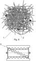
- the bunch is a spatial cluster of the mutually intertwined and randomly oriented fibers.
- the bunches can have various sizes and usually there will be a tendency to connect with the neighboring bunches; it is therefore necessary to understand "bunch” as general term for any group of disintegrated fragments of the filter material.
- the mutual connections in the bunches are based on the random intertwining of the fibers; in general the bonds of the fibers in the bunches are weak and the bunches can be separated by hand to smaller parts. This does not prevent the bunches according to this invention to be subsequently used in the applications where these bonds are strengthened by suitable additives pursuant to the particular application.
- the permeability of the flat carrier in the filter filling is usually achieved in such a way that the material of the carrier has fiber structure; the spaces between the fibers create openings for the permeation of the filter medium.
- various natural materials for this purpose which does not have to be resistant to water, btu it is always preferable of the filter filling is resistant to the random occurrence of the water, to biological degradation and so on.
- the plastic materials are used for the flat carrier, which have excellent mechanical features, too.
- Polypropylene carrier of the filter material has fine, solidly connected fibers which cross each other within a layer.
- the original fibers are placed on each other and connected during the heat in multiple layers, which creates a semi-solid plate.
- disintegration releases the bonds between the fibers.
- Most of the fibers in the emergent bunches will have similar thickness as thickness of the original fibers of the flat carrier; the fibers in the bunches will correspond to the original fibers from which the carrier has been produced. It is not impossible to produce new structures from these fibers, where for example the originally thicker fiber is divided into multiple thinner or shorter fibers.
- the bunches differentiate from the state of the art (for example SK PUV 50116-2012) also by the fact that they only involve disintegrated parts; they basically do not contain integrated pieces or fragments. If such parts are included in the bunches according to this invention, they will be only remnants within the allowed production margin.
- Total disintegration of the filter material brings about high use values - mainly heat-insulation parameters - which were only secondary in the prior state of the art.
- the disclosed method can be suitably used for the filter material without active carbon, too.
- Such filter material will be processed in the rotational disintegrator at the presence of the air and disintegrated by being repeatedly brought during the retention time into contact with the rotating elements which carry and throw away the material to the surface with the protrusions on the inner side of the cylindrical chamber of the disintegrator and by aearation bunches are created in such a way that the flat carrier is at least partially disintegrated to the original fibers, the released fibers mutually intertwine and bunches emerge in the lower part of the disintegrator and they transfer through the openings out of the chamber of the disintegrator.
- the filter material involves active carbon at least at the amount of 35 g/m 2 of the surface of the carrier, preferably from 70 g/m 2 to 1000 g/m 2 of the surface of the carrier, especially preferable from 150 g/m 2 to 430 g/m 2 of the surface of the carrier, which can constitute, for example, the active surface of the active carbon from 8 100 m 2 to 75 000 m 2 , depending on its particular features, such amounts of the active carbon at the entry point of the processing define the available amount, which can in the method according to this invention separated the separated active carbon from the active carbon processed in bunches.
- the disintegration of the carrier with the active carbon is the simultaneous separation of the active carbon from the flat carrier.
- the active carbon can be attached to the carrier by the layer of the adhesive or it can be welded to the surface of the carrier.
- a solution is common where the active carbon with the respective size of granules is closed between the two layers of the flat carrier and, at the same time, the health safe adhesive for the adhesion of the active carbon to both layers of the flat carrier is used.
- the rotating elements in the disintegrator have high kinetic energy and they repeatedly hit the carrier, which causes the release of the bond between active carbon and carrier.
- Disintegrator operates at the presence of the air on its inside; the emerging semi-finished product is areated, which significantly diminishes the specific volume weight.
- the part of the active carbon is crumbled to the smaller particles - usually to dust - which swirls inside the chamber of the disintegrator and thereby it reaches the surface of the released fibers.
- the adhesive which is eventually used for attachment of the active carbon, is separated during the processing in the disintegrator and separated from the flat carrier as well as active carbon and it can be separated from the mass of the processed semi-finished product.
- the adhesive is aggregated to the bunches which can be simply pulled out of the granulate of the active carbon.
- the disintegrator has such arrangement that the entering filter material comes into repeated contact with the rotating elements and hits the profiled surface with the protrusions on the inner side of the chamber of the disintegrator; the disintegrator therefore should not operate as a device with a continuous one-step transfer of the material such as various shredders and so on.
- the disintegrator can also be called a device for disintegration of the fiber material, cutter, grinder, mincer, or mill- even though the flat carrier according to this invention is not milled or grinded in it, but disintegrated.
- the disintegrator during the method according to this invention works with a specific time of the retention of the material and it is preferable if this retention time is adjustable.
- the disintegration of the carrier is connected with the separation of the active carbon, whereby the active carbon is crumbled and applied to the surface of the fibers and part of the active carbon in the disintegrator is separated and collected. Part of the non-crumbled active carbon can remain in the bunches where the individual granules of the carbon get stuck in the bunches of the fibers. These granules are held mechanically, compared to the thickness of the fibers they have sizes and weights which surpass the adhesive possibilities relative to the fiber.
- Dust particles of the active carbon stably adhere to the fiber which is in the intense dust whirl in the disintegrator covered basically on its whole surface. This is manifested, inter alia, by the fact that the originally white filter material is colored grey.
- the active carbon it is necessary to create the whirling of the dust of the active carbon and, at the same time, retain the material for a necessary time in the chamber of the disintegrator.
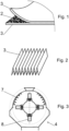
- the disintegrator involves the cylindrical chamber where the rotor with the rotating elements is rotably placed.
- These elements can be connected to the rotor by rotational studs, which allows their simply replacement or alteration of configuration with various number of rotating elements.
- the rotating elements are carried by the centrifugal force to its functional position, but in case of the hit against the solid obstacle the rotating element can be rotated along the stud, which prevents the more serious damage of the device.
- the rotor together with the elements is statically and dynamically balanced so that high rotational speed can be achieved without vibrations or noise.
- Setting the dimensions and shapes of the openings in the sieve can adjust the retention time of the material in the disintegrator.
- the material which does not fall out through the openings is repeatedly carried to the movement along the circumference of the chamber, where it is being hit by the rotating elements; the carried material is thrown to the circumference of the chamber - mainly to the surface with the protrusions.
- the dynamics of this movement are determined mainly by the circumferential speed of the rotating elements, which ranges from 20 to 300 m.s -1 , preferably 20 to 180 m.s -1 , especially preferably 45 to 100 m.s -1 .
- the bunches falling out of the disintegrator have air gaps between the fibers, which are usually several times larger than the thickness of the fibers, which significantly lowers the specific volume weight of the bunches relative to the specific volume weight of the original materials.
- the filter material can - before its entry to the disintegrator - be firstly divided to parts, fragments with the predefined approximate size. This division of the filter material unifies the dimensions of the intermediate product, which subsequently enters the disintegrator.
- the filter material of various shapes and dimensions is processed.
- the remnants of the production of the filter fillings which are processed have shapes and dimensions determined by the cutting plan; usually they will be smaller pieces originating in the space between two cut-outs and longer pieces from the edges of the semi-finished product. Among this waste there can also be whole, continuous pieces which originate during the initial placement of the semi-finished product into the technologically devices, or to the feeders, respectively.
- planar divider is preferably used for planar division - it is a rotational machine operating as a grinder or cutter which has rotating blade segments cooperating with the fixed blade segments.
- the distribution and mutual configuration of the blade segments determines the sizes of the resulting pieces of the semi-finished product.
- Planar division will usually be a one-step transfer process, preferably the semi-finished product can fall directly or through the conveyor to the feeder of the disintegrator.
- the length of the fiber which is released in the main stage of the processing will be defined by the dimensions of the semi-finished product divided in the preliminary phase.
- the size of the planar intermediate product from the preliminary phase is related to the retention time in the disintegrator, or to the degree of the disintegration in the disintegrator, respectively. If the filter material is not divided to smaller pieces, it has to remain in the disintegrator for a longer time so that the sufficient disintegration takes place. Therefore, the reduction of the intermediate product in the preliminary phase makes the operation of the disintegrator in the main phase more effective, but it is not entirely necessary for achievement of the desired result.
- Reduction or unification of the entering filter material can be realized already in the phase of production of the industrial waste. This can be achieved in such a way that during the cutting of the semi-finished products for the production of the filter fillings they are cut into the necessary shape. This means that the machine which cuts the semi-finished product itself cuts the resulting waste to required small pieces. This does not have to be complete, since small pieces on the line would complicate their transfer or removal, respectively. Individual pieces can be connected by the uncut strips, which will make the remnants connected and capable of being transferred together in one act. After their insertion to the disintegrator the small strips will be cut and the pieces of the filter material behave as if planar divided in the specialized machine within the preparation for the entry to the disintegrator. The optimal method will contain another step, where the bunches coming out of the disintegrator are sifted so that the granules of the active carbon are at least partially separated from them.
- the sifting of the bunches from the disintegrator can take place, for example, in the rotating cylindrical sieve with adjustable slope.
- the regulation of the slope and the rotation speed sets the time of the sieving of the bunch during which the bunch rolls on the sieve and the granules of the active carbon fall out.
- a conveyor sieve, or shaker screen and so on can be used; any dry sieving which does not force presses the bunches can be used. Small dust particles of the active carbon remain on the surface of the fibers.
- the process is realized at the place where the remnants of the filter materials emerge, or in the vicinity of such place.
- the waste is collected from many users; the recycling entails its transport to the place of processing.
- the method according to this invention brings advantage in the fact that it is energetically and spatially non-demanding. It is thus preferable if the filter material is processed directly in the vicinity of the place of cutting of the semi-finished product for the production of the filter fillings.
- the processing can be a final phase of the cutting of the semi-finished product from the flat strip of the filter material, or it can be a phase which is realized independently on the production of the filter inserts, but in the vicinity of this production.
- the filter material can be processed in a mobile device, too, for example within a mobile container or on a trailer of the truck, and so on.
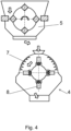
- the device for the processing of the filter material too, mainly of the filter material with the active carbon, where the filter material involves flat permeable carrier on which the active carbon in form of the granules is applied, and where the device includes a disintegrator with the rotating elements which are placed on the rotor, whereby the disintegrator has an opening for the insertion of the processed filter material in its upper part and in its lower part it has outlet openings, according to this invention, which essence lies in the fact that the disintegrator has in its upper part on the inner side of the chamber a surface with protrusions, whereby the surface is placed adjacently to the rotating elements and the distance between those elements and the protrusions is at least 3 mm, preferably at least 5 mm.
- Rotating elements do not get into direct contact with the protrusions on the inner surface of the chamber.
- the surface with the protrusions creates a narrowed section between the rotor and the chamber of the disintegrator.
- the disintegrator In the lower part the disintegrator has a broadened zone. In the narrowed zone the filter material is mechanically disintegrated; the rotating elements in this zone hit the filter material which is retained in the zone with the narrowed section.
- the broadening of the zone in the lower part creates a free space for the increasing volume of the intermediate product.
- the broadening of the space between the rotor with the blades and the inner cylindrical surface of the body of the disintegrator prevents the pressing of the intermediate product.
- the distance between the inscribed circle of the coating of the chamber with the tightened (narrowed) zone and the inscribed circle of the coating of the chamber with the broadened zone is at least one tenth of the diameter of the larger inscribed circle, whereby all circles are concentric.
- One opening has a surface size ranging from 25 mm 2 to 2500 mm 2 , preferably to 900 mm 2 . Openings in the shape of the quadrilateral with sides from 7 to 25 mm, or to 16 mm, eventually, are preferable. The change of the size of the openings alters the retention time.
- the disintegrator has horizontal axis of the rotation of the rotor with the rotating elements.
- the entry zone of the disintegrator is placed above by one edge of the rotor and the outlet zone is present below at the opposite edge of the rotor; the processed material moves from up downward.
- the disintegrator can have a sieve for separation of the active carbon, but the main part of the separation of the active carbon belongs to the sieving device of the separator, which is an independent device after the disintegrator.
- the system and the device involve the planar divider for the preparation of the intermediate product entering the disintegrator.
- the planar divider can have a form of a one-step transfer cutter, grinder, shredder, etc.
- the planar divider's function is to stabilize and unify the length, width and thickness multiplicity of the processed filter material.
- the planar divider can be rotational, too. It can consist, for example, from the cylinder in the box, where the cylinder have dividing segments on the surface, which during the rotation run by the stable dividing segments which are attached in the box.
- the gap between moving dividing segments and fixed dividing segments can range from 0,1 to 20 mm, preferably from 0,3 to 20 mm, especially preferably from 0,5 to 7 mm.
- the moving dividing segments are arranged in four lines by eight segments and distributed evenly on the outer surface of the cylinder of the planar divider.
- the moving segments can be in each line arranged in the line of the helix, thanks to which they enter gradually into grip and this prevents the simultaneous hit of multiple segments, which could lead to undesired mechanical phenomena in the system.
- a mechanical separator is part of the device; the function of the separator is to separate the active carbon from the emerged bunches.
- the separator is arranged after the outlet from the disintegrator either directly or by means of the conveyor and/or pipes.
- the separator's construction can vary according to the principle of separation in use.
- the separator can involve rotational sieve with the adjustable slope of the movement of the material in the sieve, or with adjustable rotation speed, too. The adjustment of the slope or rotation speed alters the retention time and period of rolling of the individual bunches in the sieve. The prolonging of this period diminishes the content of the active carbon in form of granules in the resulting product.
- the sieves have openings, preferably with the surface less than 9 cm 2 .
- the openings in the separator will usually be smaller than the openings in the lower part of the chamber of the disintegrator.
- the separator can in other arrangement consist of the set of vibration sieves, whereby the material regulated moves to the outlet.
- the separator includes a discharger for the discharge of the bunches.
- the discharger can be helix-shaped.
- a screw conveyor can be in the trough, whereby it transfers the active carbon out of the separator.
- planar divider, disintegrator and separator can have various mutual spatial position in the resulting system; they can be placed above each other which ensures the gravitational transfer of the material; they can be placed by each other, and so on. It is also possible to create a complex construction of the device which would involve planar divider, disintegrator and separator. This allows, for example, to diminish the total space which is necessary, or to diminish the number of the propulsive engines needed, and so on.
- the technological waste materials produced during the production of the air filters containing active carbon are used and valorized.
- the transfer of the filter materials - which are heavy burden for the environment - to the dump is either limited or entirely cancelled.
- the non-degraded active carbon is gathered; this active carbon is suitable for the repeated use for the production of the filter products containing active carbon, or for other applications.
- the invention significantly lowers the costs of energy, devices and technological procedures.
- the result of the method according to this invention is fibrous, aerated matter with low specific volume weight - lower than 1,4 g/cm 3 , preferably lower than 0,3 g/cm 3 , especially preferably lower than 0,1 g/cm 3 .
- Suitable fluffing allows one to achieve the volume weight ranging from 0,005 to 0,05 g/cm 3 .
- the fibrous matter is manifested outwardly as bunches.
- the fibers are from polymer from the polyolefin group. In preferable arrangement the fibers are from polypropylene and they are the fibers forming the original permeable carrier of the filter material.
- the polypropylene has very good chemical and mechanical resistance.
- the fibers are not oriented - they are distributed randomly and they are mutually at least partially intertwined, with the air gaps between the fibers.
- the fibers in the bunches have dust particles of the active carbon on their surfaces.
- the fibrous matter also contains the granules of the active carbon which are stuck in the gaps between the fibers.
- the content of the granules of the active carbon can be up to 87% of the mass of the resulting product, usually up to 0,01 g/cm 3 .
- the covering of the surface of the fibers with the dust from the active carbon improves the fire resistance of the resulting product.
- the polypropylene is usually used during applications with temperatures up to 110 °C, at 165 °C it starts to melt. Covering the polypropylene fibers with the active dust carbon significantly improves the heat resistance of the resulting fibrous matter. In case of the fire there is not dangerous smoke, nor are the toxic halogenated hydrocarbons released. Smoke, fumes and residues are mainly tied to the surface of the active carbon.
- the active carbon can be separated from the fibrous matter during the processing to such degree that its remaining amount in the resulting bunches will be negligible; its trace amounts will be hard to measure. In such case the active carbon will not even color the original material of the fibers and the coloring will be weak.
- the bunches can be adjusted by addition of various additives; or example a fire retardant can be added. It is preferable if the additives are added after the separation of the active carbon, so that it can be used in the pure, unadjusted state in the full-fledged application.
- the resulting product in form of bunches is preferably used as a heat and noise insulation.
- the resulting product is directly a heat insulant, or it serves as a semi-finished product for the production of various heat isolating materials, filter materials, mainly for the construction industry.
- the bunches can be a semi-finished product for other insulation or construction applications.
- Low specific volume weight at the level below 0,1 g/cm 3 expresses high share of the air in the gaps between fibers.
- the basic polypropylene has density ranging from 0,89 g/cm 3 to 0,92 g/cm 3 .
- the processing of the filter material according to this invention leads to the aeration, where the free outer volume density is significantly increased - that is, approximately ten times and more; preferably 50 to 100 times more. Even in case of small weight ratio it is capable of absorbing various dangerous substances.
- the insulation can be used in industrial applications, mainly in construction and so on.
- the product according to this invention can - in construction industry - serve mainly as an insulation-filter material with new physical and chemical dimension of the features mainly in health and hygienic fields, mainly concerning the features of antibacteriology, zero spread and growth of the molds and fungus, and effective absorption of the dust particles and harmful substances in the air.
- the resulting product of the processing is also the active carbon in form of granules itself, which can be preferably used for various applications.
- the repeated use for the production of the filter material is not ruled out, too; for example, a filter material for the air conditioning units for the filtration and recovery of the air in the industrial and pharmaceutical production, in hospitals, in electro technical industry, in food industry, or in trade and services.
- the filter material which remains from the production of the cabin air filters is being processed.
- the semi-finished product for the filter filling is cut from the strip which is rolled from the pack.
- the filter material has two layers of the flat carrier 3 , whereby the active carbon 2 is distributed among them in form of granules with the surface weight 350 g/m 2 .
- the weight of a single layer of the flat carrier 3 is 60 g/m 2 .
- the flat carrier 3 is formed by the polypropylene non-woven system of the fibers 1 with air gaps between them.
- the active carbon 2 is produced from the biological basis, for example from coconut.
- the active carbon 2 in this example is held on the flat carrier 3 by means of the harmless adhesive, which also holds both layers of the flat carrier 3 together; in other cases, the active carbon 2 can be held between the layers of the flat carrier 3 , whereby the layers are stuck together by the heat.
- the intermediate product from the planar divider 5 is together with the small amount of the released active carbon 2 transferred to the mouth of the disintegrator 4 .
- the intermediate product is captured by the rotating elements 8 of the disintegrator 4 , which have high circumferential speed.
- the elements 8 with high kinetic energy hit the pieces of the flat carrier 3 ; the hits cause disintegration in the place where the element 8 hits.
- the disintegrator 4 has a tightened, narrowed zone with the support surface in its upper part which captures the pieces so that they do not start moving concurrently with the rotation of the rotor of the disintegrator 4 .
- the pieces of the material are thrown to protrusions 7 which lead inside the chamber, whereby the protrusions 7 do not enter into direct contact with the rotating elements 8 .
- the pieces with the varying degree of disintegration head downward to the sieve in the lower part of the disintegrator 4 , whereby they are carried upward to the further contact with the rotating elements 8 in the tightened zone of the disintegrator 4 .
- the movement of the rotor of the disintegrator 4 and the movement of the elements 8 produces strong air swirl (vortex) which helps to carry the pieces from the lower part of the zone of the disintegrator 4 ; the swirl mainly distributes the dust of the active carbon 2 to the surface of the fibers 1 .
- the air swirl also causes aeration of the resulting bunches. Part of the released active carbon 2 in form of the granules falls through the sieve in the lower part of the disintegrator 4 and this active carbon 2 continues to the separator 6 .
- the bunches in the lower zone of the disintegrator 4 have a structure of the intertwined fibers 1 , whereby the active carbon 2 in form of granules is randomly captured between them.
- the rotations of the disintegrator 4 are set to achieve the circumferential speed 59 m.s -1 ; the period of retention of the material in the disintegrator 4 is on the order of the tens of seconds.
- the resulting bunches coming out through the sieve in the lower part of the disintegrator 4 have a specific volume weight 0,011 g/cm 3 in the unpressed (expanded) state.
- the material from the disintegrator 4 is transferred to the rotational separator 2 where the bunches roll and move slowly on the sloped inner surface of the cylindrical separator 6 .
- the granules of active carbon 2 are released from the bunches.
- the active carbon 2 in form of the dust particles which adhere to the surface of the fibers 1 is no longer released during the movement in the sieve in the separator 6 .
- the resulting product in this example can be used as heat or noise insulation in the building or house.
- the active carbon 2 contained in the insulation captures various smells and dangerous substances; it clears the air which runs through the vapor permeable layers of the building envelope. Thanks to the active carbon 2 the insulation is antibacterial, with zero spread and growth of molds and fungus as well as with effective capturing of the harmful substances an smells from the air.
- the cutting plan of the semi-finished product is supplied by the fact that the remnants at the same time are divided to smaller pieces. These pieces are connected with tight strips; usually each piece will have at least three connecting strips.
- the remnants of the filter material with this structure are thrown to the disintegrator 4 , where the disconnection of the connecting strips and freeing of the pieces happens at the first contact with the rotating elements 8 .
- the disintegration and aeration subsequently take place in the disintegrator 4 , as described in the previous example.
- Setting of the rotation speed of the rotor in the disintegrator, as well as retention time in the disintegrator 4 differ compared to previous example. In this example the speed of the rotating elements 8 is approximately 70 m.s -1 .
- the resulting product has specific volume weight 0,008 g/cm 3 .
- the resulting product is used as a filling for the separator of the gasoline fumes in the motor vehicle.
- the bunches do not run through the separator 6 in order to ensure high share of the active carbon 2 in form of granules, which have absorption function in the application.
- Bunches are sprayed by aerosol with flame retardants after they leave the separator 6 .
- the bunches are pressed through the hose to the gaps in building construction by means of a fan; they function as heat and noise isolation.
- Planar divider 5 in this example has simplified construction with one line of the moving segments only.
- the sieve below the cylinder of the planar divider 5 is used, too, which determines the desire size output.
Landscapes
- Chemical & Material Sciences (AREA)
- Engineering & Computer Science (AREA)
- Chemical Kinetics & Catalysis (AREA)
- Analytical Chemistry (AREA)
- Organic Chemistry (AREA)
- Food Science & Technology (AREA)
- Textile Engineering (AREA)
- Inorganic Chemistry (AREA)
- Mechanical Engineering (AREA)
- Environmental & Geological Engineering (AREA)
- General Chemical & Material Sciences (AREA)
- Oil, Petroleum & Natural Gas (AREA)
- Filtering Materials (AREA)
- Solid-Sorbent Or Filter-Aiding Compositions (AREA)
- Crushing And Pulverization Processes (AREA)
- Nonwoven Fabrics (AREA)
Claims (15)
- Anlage zum Verarbeiten von Filtermaterial mit Aktivkohle, wobei die Anlage einen Zerkleinerer (4) mit rotierenden Elementen (8) umfasst, die drehbar auf einem Rotor aufgelagert sind, wobei der Zerkleinerer (4) eine Öffnung im oberen Bereich zum Beschicken des zu verarbeitenden Filtermaterials aufweist und im unteren Bereich der Zerkleinerer (4) eine Ausgangsöffnung aufweist und die Rotordrehachse mit den rotierenden Elementen (8) im Zerkleinerer (4) horizontal ist,
dadurch gekennzeichnet, dassder Zerkleinerer (4) im oberen Bereich einen Abschnitt mit einem verengten Querschnitt aufweist, der sich zwischen dem Rotor und der Fläche mit den Vorsprüngen (7) in der Kammer des Zerkleinerers (4) befindet und im unteren Bereich einen erweiterten Abschnitt zwischen dem Rotor mit den Flügeln und der inneren zylindrischen Fläche des Körper des Zerkleinerers aufweist,innere Seite der Kammer des Zerkleinerers (4) in dem verengten Abschnitt eine Stützfläche aufweist, die gegenüber den rotierenden Elementen (8) liegt, die Stützfläche Vorsprünge (7) aufweist, die in das Innere des Zerkleinerers (4) ausgerichtet sind,der Mantel der Kammer im unteren Bereich des Zerkleinerers (4) Öffnungen zum Abwurf von Klumpen des zerfaserten Materials aufweist undzwischen den Vorsprüngen (7) und den rotierenden Elementen (8) einen Spalt von mindestens 3 mm, vorzugsweise von mindestens 5 mm vorhanden istund einen Separator (6) zum Abscheiden der Aktivkohle (2) in Form von Granulat von den Faserklumpen aufweist, wobei der Separator (6) dem Desintegrator nachgeschaltet ist (4). - Anlage zum Verarbeiten von Filtermaterial mit Aktivkohle nach dem Anspruch 1, dadurch gekennzeichnet, dass sie einen Flächentrenner (5) aufweist, der dem Zerkleinerer (4) vorgeschaltet ist, wobei der Flächentrenner (5) zum Trennen des Filtermaterials in Stücke mit den Maßen unter 10 cm vorgesehen ist.
- Anlage zum Verarbeiten von Filtermaterial mit Aktivkohle nach dem Anspruch 1 oder 2, dadurch gekennzeichnet, dass der Zerkleinerer (4) einstellbare Rotorumdrehungen und/oder einen einstellbaren Abstand der Stützfläche von den rotierenden Flügeln aufweist.
- Verfahren zur Verarbeitung des Filtermaterials mit Aktivkohle in der Anlage nach einem der Ansprüche 1 bis 3, wobei das Filtermaterial einen mindestens teilweise durchlässigen Flachträger (3) umfasst, auf dem die Aktivkohle (2) in Form von Granulat auf dem Flachträger (3) aufgetragen ist, der Flachträger (3) miteinander verbundene Faser (1) aus einem thermoplastischen Polymer aus der Gruppe der Polyolefine enthält; wobei das Filtermaterial mechanisch als Abfall ohne Wärmezufuhr verarbeitet wird,das Filtermaterial im rotierenden Zerkleinerer (4) in Anwesenheit von Luft verarbeitet wird, wobei das Material während der Verweilzeit wiederholt mit den rotierenden Elementen (8) in Kontakt gebracht wird und durch die Belüftung des Materials im Zerkleinerer (4) Klumpen entstehen, so dass der Flachträger (3) mindestens teilweise in den ursprünglichen Fasern (1) auseinandergezogen wird,wobei die aufgelockerten Fasern (1) gegenseitig verflochten werden,dadurch gekennzeichnet, dassdie Aktivkohle (2) von dem Flachträger (3) aufgelöst wird,wobei ein Teil der so aufgelösten Aktivkohle (2) durch Schläge von Elementen (8) in Staubpartikel zerlegt wird,die Rotation der Elemente (8) im Zerkleinerer (4) Luftwirbel erzeugt, der die Staubpartikel der Aktivkohle (2) mitreißt und sie auf der Oberfläche der Fasern (1) verteilt,diese Staubpartikel an der Oberfläche der Faser haften (1),im unteren Bereich des Zerkleinerers (4) die Klumpen durch die Öffnungen im Mantel des Zerkleinerers (4) nach außen treten, wobei die spezifische Schüttdichte der Faserklumpen während der Verweilzeit in der Kammer des Zerkleinerers (4) durch Belüftung abnimmtund die aus dem Zerkleinerer (4) austretenden Faserklumpen in den Separator (6) gelangen, der die Aktivkohle (2) von den Faserklumpen trennt.
- Verfahren zur Verarbeitung des Filtermaterials mit Aktivkohle nach dem Anspruch 4, dadurch gekennzeichnet, dass die Fasern (1) aus Polypropylen oder Polyethylen sind.
- Verfahren zur Verarbeitung des Filtermaterials mit Aktivkohle nach dem Anspruch 4 oder 5, dadurch gekennzeichnet, dass die Umfangsgeschwindigkeit der rotierenden Flügel 20 bis 300 m.s-1, vorzugsweise 20 bis 180 m.s-1, besonders bevorzugt 45 bis 100 m.s-1 beträgt.
- Verfahren zur Verarbeitung des Filtermaterials mit Aktivkohle nach einem der Ansprüche 4 bis 6, dadurch gekennzeichnet, dass die Verweilzeit im Zerkleinerer (4) bis zu 20 Minuten, vorzugsweise bis zu 5 Minuten, besonders bevorzugt bis zu 1 Minute beträgt.
- Verfahren zur Verarbeitung des Filtermaterials mit Aktivkohle nach einem der Ansprüche 4 bis 7, dadurch gekennzeichnet, dass das Material vor dem Eintritt in den Zerkleinerer (4) in Stücke mit den Massen von nicht mehr als 10 cm, vorzugsweise mit den Massen von nicht mehr als 6 cm oberflächlich geteilt wird, wobei das Material in einem separaten Flächentrenner (5), der dem Zerkleinerer (4) vorgeschaltet ist, oberflächlich geteilt wird.
- Verfahren zur Verarbeitung des Filtermaterials mit Aktivkohle nach dem Anspruch 8, dadurch gekennzeichnet, dass der Ausgang des Flächentrenners (5) direkt zum Eingang des Zerkleinerers (4) gelangt, wobei das Material im Flächentrenner an den Kanten zerfasert wird.
- Verfahren zur Verarbeitung des Filtermaterials mit Aktivkohle nach einem der Ansprüche 4 bis 9, dadurch gekennzeichnet, dass die den Zerkleinerer (4) verlassenden Klumpen durch ein Sieb durchgehen, durch das die Aktivkohle (2) in Form von Granulat nach unten geleitet wird.
- Verfahren zur Verarbeitung des Filtermaterials mit Aktivkohle nach einem der Ansprüche 4 bis 10, dadurch gekennzeichnet, dass die Faserklumpen im Separator (6) über eine geneigte Fläche des Rotationssiebes geführt werden, wobei die Veränderung der Neigung und/oder die Veränderung der Anzahl der Umdrehungen die Verweilzeit und damit den Gehalt an Aktivkohle (2) im resultierenden Produkt verändert.
- Verfahren zur Verarbeitung des Filtermaterials mit Aktivkohle nach einem der Ansprüche 4 bis 11, dadurch gekennzeichnet, dass die Aktivkohle (2) in Form von Granulat im Zerkleinerer (4) und/oder im Separator (6) abgetrennt wird, sich im Behälter zur weiteren Verwendung gesammelt wird.
- Verfahren zur Verarbeitung des Filtermaterials mit Aktivkohle nach einem der Ansprüche 4 bis 12, dadurch gekennzeichnet, dass beim Abtrennen der Aktivkohle (2) von dem Flachträger (3) im Zerkleinerer (4) der Klebstoff, der die Aktivkohle (2) an dem Flachträger (3) gehalten hat, abgelöst wird, vorzugsweise der Klebstoff zu Klumpen aggregiert oder der Klebstoff im Zyklonseparator (6) beim Abtrennen der Aktivkohle (2) von den Faserbüscheln abgelöst wird.
- Verfahren zur Verarbeitung des Filtermaterials mit Aktivkohle nach einem der Ansprüche 4 bis 13, dadurch gekennzeichnet, dass den Faserklumpen nach der Abtrennung der Aktivkohle (2) ein Additiv zugesetzt wird.
- Verfahren zur Verarbeitung des Filtermaterials mit Aktivkohle nach einem der Ansprüche 4 bis 13, dadurch gekennzeichnet, dass den Faserklumpen nach Abtrennung der Aktivkohle (2) ein Flammschutzmittel zugesetzt wird.
Applications Claiming Priority (4)
| Application Number | Priority Date | Filing Date | Title |
|---|---|---|---|
| SK500042016A SK288922B6 (sk) | 2016-01-15 | 2016-01-15 | Spôsob a zariadenie na spracovanie filtračného materiálu, výrobok získaný uvedeným spôsobom |
| SK50007-2016U SK7619Y1 (sk) | 2016-01-15 | 2016-01-15 | Spôsob a zariadenie na spracovanie filtračného materiálu, výrobok získaný uvedeným spôsobom |
| SK50006-2016U SK7801Y2 (sk) | 2016-01-15 | 2016-01-15 | Spôsob a zariadenie na spracovanie filtračného materiálu, výrobok získaný uvedeným spôsobom |
| PCT/IB2017/050211 WO2017122182A1 (en) | 2016-01-15 | 2017-01-15 | Method and device for processing of filter material, product obtained thereof |
Publications (3)
| Publication Number | Publication Date |
|---|---|
| EP3402913A1 EP3402913A1 (de) | 2018-11-21 |
| EP3402913C0 EP3402913C0 (de) | 2024-07-24 |
| EP3402913B1 true EP3402913B1 (de) | 2024-07-24 |
Family
ID=58410374
Family Applications (1)
| Application Number | Title | Priority Date | Filing Date |
|---|---|---|---|
| EP17713426.9A Active EP3402913B1 (de) | 2016-01-15 | 2017-01-15 | Verfahren und vorrichtung zur verarbeitung eines filtermaterials |
Country Status (5)
| Country | Link |
|---|---|
| US (1) | US11346029B2 (de) |
| EP (1) | EP3402913B1 (de) |
| CN (1) | CN108884600B (de) |
| MX (1) | MX2018008710A (de) |
| WO (1) | WO2017122182A1 (de) |
Families Citing this family (6)
| Publication number | Priority date | Publication date | Assignee | Title |
|---|---|---|---|---|
| EP3305155B1 (de) * | 2016-10-06 | 2019-05-22 | Eurofilters N.V. | Staubsaugerfilterbeutel mit recycliertem textilmaterialien und/oder baumwolllinters |
| DK180089B1 (en) | 2018-11-21 | 2020-04-17 | Campen Machinery A/S | A former head and an apparatus comprising such a former head |
| CN110420518A (zh) * | 2019-08-01 | 2019-11-08 | 广州元装滤清器有限公司 | 一种可调式滤芯铺纸模具 |
| CN112726024A (zh) * | 2020-12-31 | 2021-04-30 | 广西德福莱医疗器械有限公司 | 无异味熔喷布的制作方法 |
| EP4346934A4 (de) * | 2021-05-24 | 2025-04-30 | Battelle Memorial Institute | Behandlungen zur beschleunigung des abbaus von kunststoffen |
| FR3157235A1 (fr) * | 2023-12-20 | 2025-06-27 | Jonathan BRUNETON | Procédé de recyclage de filtres de traitement d’air usagés |
Citations (2)
| Publication number | Priority date | Publication date | Assignee | Title |
|---|---|---|---|---|
| US3925248A (en) * | 1971-05-11 | 1975-12-09 | Collo Rheincollodium Koln Gmbh | Filter medium for gases |
| US9101862B2 (en) * | 2010-04-01 | 2015-08-11 | John Andrew Timmins | Filtering machine |
Family Cites Families (13)
| Publication number | Priority date | Publication date | Assignee | Title |
|---|---|---|---|---|
| GB1224325A (en) * | 1967-11-15 | 1971-03-10 | Kroyer K K K | Apparatus for the production of fibrous sheet materials |
| US3630458A (en) * | 1969-02-10 | 1971-12-28 | Lloyd D Smiley | Turbopulp refining blender and classifier |
| JPS5230630B2 (de) * | 1974-07-08 | 1977-08-09 | ||
| DE2721511C2 (de) * | 1976-05-12 | 1985-11-28 | Honshu Seishi K.K., Tokyo | Adsorbierender, nichtgewebter Stoff und Verfahren zu dessen Herstellung |
| DE2755964C2 (de) * | 1977-12-12 | 1987-02-05 | Delbag-Luftfilter Gmbh, 1000 Berlin | Filteranordnung zur Abscheidung toxischer oder radioaktiver Stoffe aus der Atem- oder Prozeßluft, insbesondere von kerntechnischen Anlagen |
| JPS57112414A (en) | 1980-12-26 | 1982-07-13 | Daiwa Spinning Co Ltd | Purification of waste and other cotton fibers |
| DE4436337A1 (de) | 1994-10-11 | 1996-04-18 | Wilhelm Elges | Verfahren zum Recyclen von Textilfaserprodukten und Herstellung von Dämmwolle zur Wärmedämmung an Dächern und Fassaden mittels Blasversatzverfahren |
| US5535945A (en) | 1995-02-27 | 1996-07-16 | Basf Corportion | Carpet recycling process and system |
| SE9601135D0 (sv) * | 1996-03-25 | 1996-03-25 | Eka Nobel Ab | Absorbent cellulosic material and production thereof |
| US6029916A (en) * | 1998-01-16 | 2000-02-29 | Terra Technologies, Inc. | System and method for decomposing reclaiming and refusing waste carpet materials |
| US7419593B2 (en) * | 2003-11-19 | 2008-09-02 | Amcol International Corp. | Bioremediation mat and method of manufacture and use |
| US9751087B2 (en) * | 2012-09-20 | 2017-09-05 | Gary L. Watts | Comminution mill with cable impact arms |
| CN204325589U (zh) | 2014-11-07 | 2015-05-13 | 镇江垚鑫纤维制品科技有限公司 | 废旧收尘滤袋再生利用生产线 |
-
2017
- 2017-01-15 US US16/069,901 patent/US11346029B2/en active Active
- 2017-01-15 CN CN201780011320.9A patent/CN108884600B/zh active Active
- 2017-01-15 WO PCT/IB2017/050211 patent/WO2017122182A1/en not_active Ceased
- 2017-01-15 EP EP17713426.9A patent/EP3402913B1/de active Active
- 2017-01-15 MX MX2018008710A patent/MX2018008710A/es unknown
Patent Citations (2)
| Publication number | Priority date | Publication date | Assignee | Title |
|---|---|---|---|---|
| US3925248A (en) * | 1971-05-11 | 1975-12-09 | Collo Rheincollodium Koln Gmbh | Filter medium for gases |
| US9101862B2 (en) * | 2010-04-01 | 2015-08-11 | John Andrew Timmins | Filtering machine |
Also Published As
| Publication number | Publication date |
|---|---|
| EP3402913C0 (de) | 2024-07-24 |
| CN108884600B (zh) | 2022-05-27 |
| US11346029B2 (en) | 2022-05-31 |
| US20190017202A1 (en) | 2019-01-17 |
| MX2018008710A (es) | 2019-05-27 |
| CN108884600A (zh) | 2018-11-23 |
| EP3402913A1 (de) | 2018-11-21 |
| WO2017122182A4 (en) | 2017-08-31 |
| WO2017122182A1 (en) | 2017-07-20 |
Similar Documents
| Publication | Publication Date | Title |
|---|---|---|
| EP3402913B1 (de) | Verfahren und vorrichtung zur verarbeitung eines filtermaterials | |
| US20220314496A1 (en) | Processes and structures for recycling carpet and products of such processes | |
| JP6500329B2 (ja) | シート製造装置 | |
| JP6996238B2 (ja) | 繊維原料再生装置 | |
| US9975270B2 (en) | Method for manufacturing an aerogel-containing composite and composite produced by that method | |
| AU2008209312A1 (en) | Method and apparatus for manufacturing a product of integrated cellulose and fibrous materials | |
| JP2020153037A (ja) | ウェブ構造体、及び、ウェブ構造体の製造装置 | |
| KR102160927B1 (ko) | 특히 건축 산업용 건자재로서의 터프트 물질, 그 제조 방법 및 그 제조 기계 | |
| JPWO2018101125A1 (ja) | 集塵装置、及び、シート製造装置 | |
| JPH09119082A (ja) | 皮革粉を形成する装置 | |
| SK500062016U1 (sk) | Spôsob a zariadenie na spracovanie filtračného materiálu, výrobok získaný uvedeným spôsobom | |
| SK500042016A3 (sk) | Spôsob a zariadenie na spracovanie filtračného materiálu, výrobok získaný uvedeným spôsobom | |
| JPWO2018100989A1 (ja) | ウェブ形成装置およびシート製造装置 | |
| SK7619Y1 (sk) | Spôsob a zariadenie na spracovanie filtračného materiálu, výrobok získaný uvedeným spôsobom | |
| HRP980306A2 (en) | Production of man-made vitreous fibre products | |
| CN218531749U (zh) | 一种用于燃煤机组大比例掺烧生物质的大块筛除系统 | |
| US11707745B2 (en) | Processes and structures for plastic separation and products of such processes | |
| JPS6221507B2 (de) | ||
| SK6673Y1 (sk) | Chumáčovina ako konštrukčný materiál, najmä pre stavebníctvo, spôsob jej výroby a zariadenie na jej výrobu | |
| JP2005007367A (ja) | 粉砕システム |
Legal Events
| Date | Code | Title | Description |
|---|---|---|---|
| STAA | Information on the status of an ep patent application or granted ep patent |
Free format text: STATUS: UNKNOWN |
|
| STAA | Information on the status of an ep patent application or granted ep patent |
Free format text: STATUS: THE INTERNATIONAL PUBLICATION HAS BEEN MADE |
|
| PUAI | Public reference made under article 153(3) epc to a published international application that has entered the european phase |
Free format text: ORIGINAL CODE: 0009012 |
|
| STAA | Information on the status of an ep patent application or granted ep patent |
Free format text: STATUS: REQUEST FOR EXAMINATION WAS MADE |
|
| 17P | Request for examination filed |
Effective date: 20180814 |
|
| AK | Designated contracting states |
Kind code of ref document: A1 Designated state(s): AL AT BE BG CH CY CZ DE DK EE ES FI FR GB GR HR HU IE IS IT LI LT LU LV MC MK MT NL NO PL PT RO RS SE SI SK SM TR |
|
| AX | Request for extension of the european patent |
Extension state: BA ME |
|
| DAV | Request for validation of the european patent (deleted) | ||
| DAX | Request for extension of the european patent (deleted) | ||
| STAA | Information on the status of an ep patent application or granted ep patent |
Free format text: STATUS: EXAMINATION IS IN PROGRESS |
|
| 17Q | First examination report despatched |
Effective date: 20200416 |
|
| REG | Reference to a national code |
Ref legal event code: R079 Ipc: B01D0039020000 Ref country code: DE Ref legal event code: R079 Ref document number: 602017083495 Country of ref document: DE Free format text: PREVIOUS MAIN CLASS: D01G0011000000 Ipc: B01D0039020000 |
|
| GRAP | Despatch of communication of intention to grant a patent |
Free format text: ORIGINAL CODE: EPIDOSNIGR1 |
|
| STAA | Information on the status of an ep patent application or granted ep patent |
Free format text: STATUS: GRANT OF PATENT IS INTENDED |
|
| RIC1 | Information provided on ipc code assigned before grant |
Ipc: B02C 13/02 20060101ALI20231115BHEP Ipc: B02C 13/282 20060101ALI20231115BHEP Ipc: B01J 20/28 20060101ALI20231115BHEP Ipc: B01J 20/26 20060101ALI20231115BHEP Ipc: B01J 20/30 20060101ALI20231115BHEP Ipc: B01J 20/20 20060101ALI20231115BHEP Ipc: D01G 17/00 20060101ALI20231115BHEP Ipc: D01G 11/00 20060101ALI20231115BHEP Ipc: D04H 1/4291 20120101ALI20231115BHEP Ipc: D04H 1/407 20120101ALI20231115BHEP Ipc: B01D 39/02 20060101AFI20231115BHEP |
|
| INTG | Intention to grant announced |
Effective date: 20231219 |
|
| GRAS | Grant fee paid |
Free format text: ORIGINAL CODE: EPIDOSNIGR3 |
|
| GRAA | (expected) grant |
Free format text: ORIGINAL CODE: 0009210 |
|
| STAA | Information on the status of an ep patent application or granted ep patent |
Free format text: STATUS: THE PATENT HAS BEEN GRANTED |
|
| AK | Designated contracting states |
Kind code of ref document: B1 Designated state(s): AL AT BE BG CH CY CZ DE DK EE ES FI FR GB GR HR HU IE IS IT LI LT LU LV MC MK MT NL NO PL PT RO RS SE SI SK SM TR |
|
| REG | Reference to a national code |
Ref country code: GB Ref legal event code: FG4D |
|
| REG | Reference to a national code |
Ref country code: CH Ref legal event code: EP |
|
| REG | Reference to a national code |
Ref country code: IE Ref legal event code: FG4D Ref country code: DE Ref legal event code: R096 Ref document number: 602017083495 Country of ref document: DE |
|
| U01 | Request for unitary effect filed |
Effective date: 20240822 |
|
| U07 | Unitary effect registered |
Designated state(s): AT BE BG DE DK EE FI FR IT LT LU LV MT NL PT RO SE SI Effective date: 20240902 |
|
| PG25 | Lapsed in a contracting state [announced via postgrant information from national office to epo] |
Ref country code: NO Free format text: LAPSE BECAUSE OF FAILURE TO SUBMIT A TRANSLATION OF THE DESCRIPTION OR TO PAY THE FEE WITHIN THE PRESCRIBED TIME-LIMIT Effective date: 20241024 |
|
| PG25 | Lapsed in a contracting state [announced via postgrant information from national office to epo] |
Ref country code: GR Free format text: LAPSE BECAUSE OF FAILURE TO SUBMIT A TRANSLATION OF THE DESCRIPTION OR TO PAY THE FEE WITHIN THE PRESCRIBED TIME-LIMIT Effective date: 20241025 Ref country code: PL Free format text: LAPSE BECAUSE OF FAILURE TO SUBMIT A TRANSLATION OF THE DESCRIPTION OR TO PAY THE FEE WITHIN THE PRESCRIBED TIME-LIMIT Effective date: 20240724 |
|
| PG25 | Lapsed in a contracting state [announced via postgrant information from national office to epo] |
Ref country code: IS Free format text: LAPSE BECAUSE OF FAILURE TO SUBMIT A TRANSLATION OF THE DESCRIPTION OR TO PAY THE FEE WITHIN THE PRESCRIBED TIME-LIMIT Effective date: 20241124 |
|
| PG25 | Lapsed in a contracting state [announced via postgrant information from national office to epo] |
Ref country code: HR Free format text: LAPSE BECAUSE OF FAILURE TO SUBMIT A TRANSLATION OF THE DESCRIPTION OR TO PAY THE FEE WITHIN THE PRESCRIBED TIME-LIMIT Effective date: 20240724 |
|
| PG25 | Lapsed in a contracting state [announced via postgrant information from national office to epo] |
Ref country code: ES Free format text: LAPSE BECAUSE OF FAILURE TO SUBMIT A TRANSLATION OF THE DESCRIPTION OR TO PAY THE FEE WITHIN THE PRESCRIBED TIME-LIMIT Effective date: 20240724 Ref country code: RS Free format text: LAPSE BECAUSE OF FAILURE TO SUBMIT A TRANSLATION OF THE DESCRIPTION OR TO PAY THE FEE WITHIN THE PRESCRIBED TIME-LIMIT Effective date: 20241024 |
|
| PG25 | Lapsed in a contracting state [announced via postgrant information from national office to epo] |
Ref country code: RS Free format text: LAPSE BECAUSE OF FAILURE TO SUBMIT A TRANSLATION OF THE DESCRIPTION OR TO PAY THE FEE WITHIN THE PRESCRIBED TIME-LIMIT Effective date: 20241024 Ref country code: PL Free format text: LAPSE BECAUSE OF FAILURE TO SUBMIT A TRANSLATION OF THE DESCRIPTION OR TO PAY THE FEE WITHIN THE PRESCRIBED TIME-LIMIT Effective date: 20240724 Ref country code: NO Free format text: LAPSE BECAUSE OF FAILURE TO SUBMIT A TRANSLATION OF THE DESCRIPTION OR TO PAY THE FEE WITHIN THE PRESCRIBED TIME-LIMIT Effective date: 20241024 Ref country code: IS Free format text: LAPSE BECAUSE OF FAILURE TO SUBMIT A TRANSLATION OF THE DESCRIPTION OR TO PAY THE FEE WITHIN THE PRESCRIBED TIME-LIMIT Effective date: 20241124 Ref country code: HR Free format text: LAPSE BECAUSE OF FAILURE TO SUBMIT A TRANSLATION OF THE DESCRIPTION OR TO PAY THE FEE WITHIN THE PRESCRIBED TIME-LIMIT Effective date: 20240724 Ref country code: GR Free format text: LAPSE BECAUSE OF FAILURE TO SUBMIT A TRANSLATION OF THE DESCRIPTION OR TO PAY THE FEE WITHIN THE PRESCRIBED TIME-LIMIT Effective date: 20241025 Ref country code: ES Free format text: LAPSE BECAUSE OF FAILURE TO SUBMIT A TRANSLATION OF THE DESCRIPTION OR TO PAY THE FEE WITHIN THE PRESCRIBED TIME-LIMIT Effective date: 20240724 |
|
| U20 | Renewal fee for the european patent with unitary effect paid |
Year of fee payment: 9 Effective date: 20250113 |
|
| PG25 | Lapsed in a contracting state [announced via postgrant information from national office to epo] |
Ref country code: SM Free format text: LAPSE BECAUSE OF FAILURE TO SUBMIT A TRANSLATION OF THE DESCRIPTION OR TO PAY THE FEE WITHIN THE PRESCRIBED TIME-LIMIT Effective date: 20240724 |
|
| PGFP | Annual fee paid to national office [announced via postgrant information from national office to epo] |
Ref country code: CZ Payment date: 20250114 Year of fee payment: 9 |
|
| PG25 | Lapsed in a contracting state [announced via postgrant information from national office to epo] |
Ref country code: SK Free format text: LAPSE BECAUSE OF FAILURE TO SUBMIT A TRANSLATION OF THE DESCRIPTION OR TO PAY THE FEE WITHIN THE PRESCRIBED TIME-LIMIT Effective date: 20240724 |
|
| PGFP | Annual fee paid to national office [announced via postgrant information from national office to epo] |
Ref country code: GB Payment date: 20250113 Year of fee payment: 9 |
|
| PLBE | No opposition filed within time limit |
Free format text: ORIGINAL CODE: 0009261 |
|
| STAA | Information on the status of an ep patent application or granted ep patent |
Free format text: STATUS: NO OPPOSITION FILED WITHIN TIME LIMIT |
|
| 26N | No opposition filed |
Effective date: 20250425 |
|
| REG | Reference to a national code |
Ref country code: CH Ref legal event code: PL |
|
| PG25 | Lapsed in a contracting state [announced via postgrant information from national office to epo] |
Ref country code: MC Free format text: LAPSE BECAUSE OF FAILURE TO SUBMIT A TRANSLATION OF THE DESCRIPTION OR TO PAY THE FEE WITHIN THE PRESCRIBED TIME-LIMIT Effective date: 20240724 |
|
| PG25 | Lapsed in a contracting state [announced via postgrant information from national office to epo] |
Ref country code: CH Free format text: LAPSE BECAUSE OF NON-PAYMENT OF DUE FEES Effective date: 20250131 |