EP3402712B1 - Vehicle rear wing with adaptive section and extendable flap - Google Patents
Vehicle rear wing with adaptive section and extendable flap Download PDFInfo
- Publication number
- EP3402712B1 EP3402712B1 EP17701253.1A EP17701253A EP3402712B1 EP 3402712 B1 EP3402712 B1 EP 3402712B1 EP 17701253 A EP17701253 A EP 17701253A EP 3402712 B1 EP3402712 B1 EP 3402712B1
- Authority
- EP
- European Patent Office
- Prior art keywords
- moveable element
- flap
- configuration
- lift
- pair
- Prior art date
- Legal status (The legal status is an assumption and is not a legal conclusion. Google has not performed a legal analysis and makes no representation as to the accuracy of the status listed.)
- Active
Links
- 230000003044 adaptive effect Effects 0.000 title description 2
- 230000007246 mechanism Effects 0.000 claims description 34
- 230000008859 change Effects 0.000 claims description 5
- 230000004044 response Effects 0.000 claims description 2
- 230000001131 transforming effect Effects 0.000 claims 2
- 230000000694 effects Effects 0.000 description 4
- 230000008901 benefit Effects 0.000 description 3
- 238000002955 isolation Methods 0.000 description 3
- 238000013519 translation Methods 0.000 description 2
- 238000013459 approach Methods 0.000 description 1
- 230000007423 decrease Effects 0.000 description 1
- 238000011161 development Methods 0.000 description 1
- 230000009977 dual effect Effects 0.000 description 1
- 239000012530 fluid Substances 0.000 description 1
- 239000000446 fuel Substances 0.000 description 1
- 238000000034 method Methods 0.000 description 1
- 238000012986 modification Methods 0.000 description 1
- 230000004048 modification Effects 0.000 description 1
- 230000000153 supplemental effect Effects 0.000 description 1
- 230000007704 transition Effects 0.000 description 1
Images


Classifications
-
- B—PERFORMING OPERATIONS; TRANSPORTING
- B62—LAND VEHICLES FOR TRAVELLING OTHERWISE THAN ON RAILS
- B62D—MOTOR VEHICLES; TRAILERS
- B62D35/00—Vehicle bodies characterised by streamlining
- B62D35/007—Rear spoilers
-
- B—PERFORMING OPERATIONS; TRANSPORTING
- B62—LAND VEHICLES FOR TRAVELLING OTHERWISE THAN ON RAILS
- B62D—MOTOR VEHICLES; TRAILERS
- B62D37/00—Stabilising vehicle bodies without controlling suspension arrangements
- B62D37/02—Stabilising vehicle bodies without controlling suspension arrangements by aerodynamic means
-
- Y—GENERAL TAGGING OF NEW TECHNOLOGICAL DEVELOPMENTS; GENERAL TAGGING OF CROSS-SECTIONAL TECHNOLOGIES SPANNING OVER SEVERAL SECTIONS OF THE IPC; TECHNICAL SUBJECTS COVERED BY FORMER USPC CROSS-REFERENCE ART COLLECTIONS [XRACs] AND DIGESTS
- Y02—TECHNOLOGIES OR APPLICATIONS FOR MITIGATION OR ADAPTATION AGAINST CLIMATE CHANGE
- Y02T—CLIMATE CHANGE MITIGATION TECHNOLOGIES RELATED TO TRANSPORTATION
- Y02T10/00—Road transport of goods or passengers
- Y02T10/80—Technologies aiming to reduce greenhouse gasses emissions common to all road transportation technologies
- Y02T10/82—Elements for improving aerodynamics
Definitions
- This invention relates to a deployable vehicle rear wing that adaptively optimizes its cross sectional shape during operation while simultaneously extending a trailing edge Gurney flap.
- Deployable rear aerodynamic elements generally cannot offer high operating efficiency as their geometric section is typically limited by the vehicle styling.
- the present invention overcomes this limitation by automatically modifying the aerodynamic element's geometric shape as it is deployed, so as to produce a highly efficient airfoil section with an extended Gurney flap, using a simple mechanical linkage.
- a wing section mounted on the rear of a vehicle is desirable as it increases aerodynamic downforce which ultimately improves handling performance.
- a supplemental wing increases aerodynamic drag and therefore degrades fuel economy and maximum speed capability of the vehicle.
- deployable aerodynamic elements that can be retracted to achieve relatively low drag and extended when higher vehicle dynamic performance is required.
- the limitation of most deployable aerodynamic elements is that their geometric section is typically forced to conform to the vehicle styling, which limits efficiency.
- the aerodynamic efficiency refers to the ratio of lift to drag, or L/D, where lift is the opposite of downforce, so represented as a negative number on a vehicle.
- US7213870 to Williams describes a novel adjustable rear wing that is fixed to the vehicle in which both the chord length and angle of attack of the section can be adaptively changed using actuators and a controller. In this manner the L/D of the rear wing can be automatically modified during vehicle operation.
- US4773692 to Schleicher et al. describes a deployable rear spoiler that can be moved between a retracted position and an extended position using a novel mechanical arrangement that creates a dual motion that moves the deployable rear spoiler, or air deflector, away from the vehicle body and to an inclined position.
- the mechanical arrangement consists of an arcuate adjuster and guide channel in conjunction with an electric motor and cable drive.
- the cross section of the air deflector is clearly not of an optimized airfoil shape as it has been designed to conform to the styled shape of the vehicle body when in its retracted position.
- US4854635 to Durm et al. specifically claims a unique drive mechanism for the moving of an air guide arrangement on the rear of a vehicle from a retracted rest position to an extended operating position.
- the air guide device itself is clearly illustrated as a moveable panel on the sloping rear side of the vehicle which has no resemblance to an airfoil cross section and appears to function purely as a method of creating a discontinuity in the flow field of the air travelling over the body of the vehicle.
- a spoiler performs a significantly different function than a wing in that it is simply configured to eliminate the positive lift that the styled shape of the vehicle body creates.
- US8113571 to Goenueldine describes an air guiding device on the rear end of a vehicle which is moveable relative to the rear end using a setting-out mechanism.
- the '571 patent claims a novel approach for the attachment of the setting-out mechanism to the underside of the air guiding device so as to help improve its aerodynamic and aeroacoustic performance
- the cross section of the air guiding device described as both a wing and a spoiler
- the styled shape of the vehicle body appears to have been created to be of an aerodynamically efficient shape so that the moveable air guiding device is closer to an optimal cross section when deployed. Aspects of the shape, such as the blunt trailing edge, which is configured to match the vehicle body, still significantly reduce the L/D efficiency of the air guiding device.
- US8944489 to Patterson et al. claims a variable aerodynamic device for a vehicle that is configured to move a wing element between a raised position and a lowered position relative to the vehicle body and additionally to a third, air brake condition when required.
- the deployment mechanism is configured to be driven by hydraulic actuators via a novel guide strut and linkage arrangement that results in a low angle of attack in the lowered position, an increased angle of attack in the raised position and an extreme, high drag, angle of attack in the air brake position.
- the wing element develops minimal drag and also downforce in the lowered position, increased downforce as well as drag in the raised position and extremely high drag in the air brake position with some increase in downforce.
- the L/D efficiency in this third position would be extremely poor due to an undesirable aerodynamic characteristic known as stall in which the air flow on the underside of the wing element separates from the surface and causes significant disruption to the flow field so that Bernoulli's principle no longer applies. It is also evident from the illustrations that the wing element of the '489 patent does not conform to a classic airfoil cross section so as to match the styled surface of the vehicle body in the lowered position and so the L/D efficiency of the wing element would be far from optimized.
- the lift and drag of optimized wing sections can be modified by adding extensions to the main surfaces known as flaps or slats.
- these extensions are configured to be deployable and create increased lift at lower air speed as an aid to take-off and landing.
- the deployment of these devices generally increases drag proportionally and in most cases actually decreases the L/D efficiency of the wing.
- the devices are retracted for normal flight as the additional lift is not required and the increased drag would be highly undesirable.
- the addition of a relatively small upstanding, thin section flap at the trailing edge of a wing section creates an increase in downforce disproportionally larger than the increase in drag, therefore resulting in a higher L/D efficiency.
- Gurney flap The parameters associated with the thickness and height limitations to achieve the increase in L/D are well known and the device is generally referred to as a Gurney flap.
- the fixed wings on competition vehicles are rarely implemented without Gurney flaps.
- the use of Gurney flaps on deployable vehicle rear wings has not been adopted as the upstanding flap would create considerable drag in the retracted position and be difficult to match to the styled surface of the vehicle body.
- the flap, or spoiler, of both the '635 and '281 patents eliminates the positive lift that the styled shape that the vehicle body creates, but has no air flow underneath the element in its operative position which is a critical operating requirement of an airfoil wing.
- An additional novelty of the '281 invention is the inclusion of an air current breakaway element which is constructed separately from the flap and independently extends in the transverse direction of the vehicle, in the operative position of the spoiler arrangement, the breakaway element extending adjacent to the rear edge of the flap.
- this breakaway element is a thin section, vertically oriented feature at the trailing edge of the main spoiler, it is not a Gurney flap as the main section that it modifies is not an airfoil and so the aerodynamic effect would not increase the L/D as there is no efficiency associated with the isolated element.
- a deployable vehicle rear wing includes a rear mounted moveable element constructed from a main upper surface and a hinged lower surface that in a first configuration closely conforms to the surrounding styled surface of the vehicle body and in a second configuration provides an airfoil section with an integrated Gurney flap that is configured to provide an extended position.
- a lift mechanism includes an arrangement of rotating linkages and sliding components such that a first actuator is configured to drive a pair of fixed arms to move the moveable element between a stowed position and a deployed position.
- the lift mechanism includes a second pair of actuators interconnected to the moveable element and the rotating linkages. The second actuators are configured to move the moveable element between the deployed position and an air brake position.
- a flap linkage is packaged within the moveable element and coupled between the main upper surface and the hinged lower surface.
- the flap linkage incorporates a cam affixed with respect to the fixed arm so that the flap linkage is configured to move the hinged lower surface to the second configuration with the Gurney flap in the extended position in response to a change in relative position between the cam and the flap linkage.
- the lift mechanism includes a support structure.
- a pair of lift levers are pivotally mounted to the support structure.
- the pair of fixed arms are interconnected to the lift levers.
- a pair of guide collars are pivotally mounted to the support structure.
- the first actuator is interconnected to the lift levers and the support structure and is configured to move the moveable element between the stowed position and the deployed position by rotating the lift levers and causing the fixed arms to rise through the guide collars.
- the second pair of actuators are interconnected to the moveable element and the lift lever.
- the cam is coupled to a distal end of the fixed arms where they are rotationally mounted to the moveable element.
- a drive link is pivotally attached to the main upper surface at one end and to the hinged lower surface via a slotted rotational joint at another end so that as the lift mechanism deploys the moveable element, initially in the first configuration, the flap linkage pivots the hinged lower surface towards the main upper surface creating the second configuration.
- An airfoil section with a blunt rear section of the first configuration transforms the blunt rear section into the vertically oriented Gurney flap.
- the lift mechanism is configured to move the moveable element upward and rearward along an arcuate path from the stowed position to the deployed position.
- the plan view shape of the moveable element includes a reduced centre cross section.
- the hinged lower surface is broken into two parts at the outer ends of the moveable element.
- Two identical flap linkages are utilized and driven individually by each of the two fixed arms.
- first and second actuators are hydraulic.
- the second actuators each include a spring arranged beneath a cover that is secured to a cylinder that includes a flange.
- a rod of each of the second actuators is telescopically arranged with respect to the cylinder of the respective second actuator.
- the spring is in a compressed state between the flange and the cover of the respective second actuator in an extended actuator position.
- the spring is configured to force the respective rod into the respective cylinder to a collapsed position that provides the air brake position.
- a deployable vehicle rear wing in another exemplary embodiment, includes a rear mounted moveable element constructed from a main upper surface and a hinged lower surface. In a first configuration it closely conforms to the surrounding styled surface of the vehicle body and in a second configuration it provides an airfoil section with an integrated Gurney flap that is configured to provide an extended position.
- a lift mechanism includes a support structure. A pair of lift levers are pivotally mounted to the support structure. A pair of fixed arms are interconnected to the lift levers and cooperate with a pair of guide collars pivotally mounted to the support structure.
- a first actuator is interconnected to the lift levers and the support structure and is configured to move the moveable element between a stowed position and a deployed position by rotating the lift levers and causing the fixed arms to rise through the guide collars.
- a second pair of actuators are interconnected to the moveable element and the lift levers. The second actuators are configured to move the moveable element between the deployed position and an air brake position.
- a flap linkage is packaged within the moveable element that includes a cam that is coupled to a distal end of the fixed arms where they are rotationally mounted to the moveable element.
- a drive link is rotationally attached to the main upper surface at one end and to the hinged lower surface via a slotted rotational joint at another end so that as the lift mechanism deploys the moveable element, initially in the first configuration, the flap linkage pivots the hinged lower surface towards the main upper surface creating the second configuration.
- An airfoil section with a blunt rear section of the first configuration transforms the blunt rear section into the vertically oriented Gurney flap.
- the lower surface of a moveable element is adapted to hinge around a predetermined point so that as the moveable element is moved between a stowed and deployed position, the lower surface is rotated around the hinge axis to eliminate the blunt trailing edge of the section, defined by the vehicle body, to create a highly desirable sharp trailing edge with a vertically extending Gurney flap.
- a main lift mechanism creates a combined motion path that lifts the moveable element into the free stream of air passing over the vehicle while also increasing its angle of attack.
- the cross section change is driven by a linkage arrangement that is coupled to the main deployment motion so that when the moveable element is fully deployed, with an associated vertical lift and increased angle of attack, it is also a fully optimized airfoil section with an associated high L/D efficiency.
- the moveable element provides an aesthetically pleasing shape that conforms to the styled surface of the vehicle body and creates very little drag or downforce in its stowed position.
- the moveable element provides a highly efficient airfoil section with an integrated Gurney flap that is located in the free stream air flow over the vehicle with an optimized angle of attack to provide a high level of downforce with an efficient L/D.
- An additional feature of the lift mechanism is an ability to generate an extreme angle of attack during selected events such as high braking demand so that aerodynamic drag assists in decelerating the vehicle.
- a consequence of this air brake position is a highly inefficient element that results in aerodynamic stall but extremely high drag. In this condition the lower surface of the moveable element returns to its stowed position shape with the Gurney flap retracted.
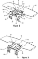
- Figure 1 illustrates the rear of a vehicle body 10 with an integrated moveable element 16 that is designed to conform to the styled surface of the vehicle body 10.
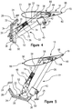
- Figure 2 shows a perspective view of the moveable element 16 and a lift mechanism 22 that translates the moveable element 16 rearward, upwards and into positive angle of attack along an arcuate path from stowed position shown in Figure 4 to a deployed position shown in Figure 5 .
- the lift mechanism 22 includes a support structure 24 , as best shown in Figure 2 , which is secured to the vehicle body.
- the support structure 24 includes first and second brackets 29 , 31 .
- a pair of lift levers 26 are mounted for rotation with respect to the support structure 24 by first pivotal connections 28 provided by the first brackets 29.
- a first actuator 30 (e.g., hydraulic), which includes a cylinder 33 and a rod 35, is interconnected between the support structure 24 and the lift levers 26 via a bar 32 at second pivotal connection 34.
- the rod 35 is retracted from the stowed position to move the moveable element 16 to the deployed position, which rotates the lift levers 26 rearward about the first pivotal connections 28.
- a pair of fixed arms 36 are secured between each pair of lift levers 26 at third pivotal connections 38.
- a pair of guide collars 40 are slidably received on each fixed arm 36 and secured to the support structure 24 via the second brackets 31 at a fourth pivotal connection 42.
- An end of the fixed arms 36 opposite the lift levers 26 is connected to the moveable element 16 at fifth pivotal connections 44.
- a second pair of actuators 46 (e.g., hydraulic) are secured between each pair of lift levers 26 by a leg 48 secured at sixth pivotal connections 50.
- the second actuators 46 include a cylinder 52 secured to its respective leg 48 , and a rod 54 extends from the cylinder 52 and is connected to the moveable element 16 at seventh pivotal connections 56.
- the second actuators 46 are in an extended position throughout the stowed and deployed positions.
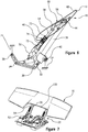
- the moveable element 16 includes a main upper surface 58 with a trailing edge 68 and a hinged lower surface 60.
- the moveable element includes a stiffening rib 62 extending laterally within its interior volume.
- the hinged lower surface 60 includes a lip 70 arranged near the trailing edge 68.
- the hinged lower surface 60 is rotationally secured to the main upper surface 58 via a hinge 64 at the stiffening rib 62.
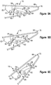
- the main upper surface 58 and hinged lower surface 60 create an exterior surface 66 that in a first configuration, best illustrated in Figure 8A , conforms to the surrounding styled surface of the vehicle body, and in a second configuration, best illustrated in Figure 8B , provides a highly efficient airfoil section with an integrated Gurney flap.
- the transition of the exterior surface 66 of the moveable element 16 from the first configuration to the second configuration is coupled directly to the translation of the lift mechanism 22 from the stowed position shown in Figure 4 to a deployed position shown in Figure 5 .
- the lift levers 26 are rotated upward and rearward, sliding the fixed arms 36 upward through the guide collars 40. Due to the geometry of the components of the lift mechanism 22 , as the moveable element 16 is translated rearward and upward its angle of attack is also increased.
- the hinged lower surface 60 is driven between the first configuration and the second configuration without using a separate actuator, although one may be used if desired. Instead, the hinged lower surface is passively driven using interlinked components moved by virtue of the lift mechanism's 22 changing geometry, which is described in more detail in connection with Figures 8A-8B .
- the hinged lower surface 60 moves to the second configuration, which extends the lip 70 beyond the trailing edge 68. In this manner the lip 70 creates the effect of a Gurney flap on a sharp trailing edge airfoil which significantly increases the aerodynamic efficiency of the deployed moveable element.
- the second actuators 46 each include a spring 74 arranged beneath a cover 73 that is secured to the cylinder 52.
- the rod 54 cooperates with the cylinder 52 and includes a flange 72.
- the spring 74 is in a compressed state between the flange 72 and cover 73 with the second actuators 46 in the extended position.
- a hydraulic valve associated with the cylinder 52 is opened, which enables the spring 74 to force the rod 54 into the cylinder 52 thereby collapsing the second actuators 46.
- Aerodynamic forces on the moveable element 16 assist in the collapse of the second actuators 46 , which are attached at a pivotal connection 56 which is located ahead of the fixed arm's 36 pivotal connection 44.
- the hinged lower surface 60 returns to its first configuration, with the Gurney flap retracted, when the moveable element 16 moves to the air brake position.
- a shaft 76 extends laterally outward from each fixed arm 36 coaxially with the pivotal connections 44. Each shaft 76 is rotationally fixed with respect to the pivotal connections 44 by interlocking features.
- a first support bracket 82 is secured to the main upper surface 58
- a second support bracket 84 is secured to hinged lower surface 60.
- a flap linkage 86 is coupled between the first and second support brackets 82 , 84.
- the hinged lower surface 60 is broken into two parts at the outer ends of the moveable element 16 , as shown by the hidden lines in Figure 7 .
- the plan view shape of the moveable element 16 includes a reduced centre cross section 120. Two identical flap linkages 86 are utilized and driven individually by each of the two fixed arms 36.
- the flap linkage 86 includes a drive link 88 attached to the first support bracket 82 at one end by a pivot 90.
- the second support bracket 84 includes a slot 95 that receives a first pin 94 at the other end of the drive link 88.
- the slot 95 enables the hinged lower surface 60 to be secured to the main upper surface 58 during assembly with the drive link 88 already installed on the first support bracket 82.
- the flap linkage 86 includes a cam 92 that is affixed to the shaft 76.
- a second pin 96 extending from the drive link 88 is received within a slot 98 in the cam 92 to provide a slotted rotational joint that includes a ramped surface 100.
- the second pin 96 is shown in three positions which respectively correspond to the moveable element 16 being in the stowed, deployed and air brake positions.
- the shaft 76 maintains the position of the cam 92 throughout all operational positions of the moveable element 16.
- the moveable element 16 articulates with respect to the cam 92 as the geometry of the lift mechanism 22 changes.
- the drive link 88 cants upward causing the second pin 96 to move up the ramped surface 100 which rotates the hinged lower surface 60 around the hinge 64 towards the main upper surface 58 as the first pin 94 pulls upward on the second support bracket 84.
Landscapes
- Engineering & Computer Science (AREA)
- Chemical & Material Sciences (AREA)
- Combustion & Propulsion (AREA)
- Transportation (AREA)
- Mechanical Engineering (AREA)
- Physics & Mathematics (AREA)
- Fluid Mechanics (AREA)
- Body Structure For Vehicles (AREA)
Applications Claiming Priority (2)
| Application Number | Priority Date | Filing Date | Title |
|---|---|---|---|
| US201662277045P | 2016-01-11 | 2016-01-11 | |
| PCT/US2017/013028 WO2017123640A2 (en) | 2016-01-11 | 2017-01-11 | Vehicle rear wing with adaptive section and extendable flap |
Publications (2)
| Publication Number | Publication Date |
|---|---|
| EP3402712A2 EP3402712A2 (en) | 2018-11-21 |
| EP3402712B1 true EP3402712B1 (en) | 2019-12-11 |
Family
ID=57868427
Family Applications (1)
| Application Number | Title | Priority Date | Filing Date |
|---|---|---|---|
| EP17701253.1A Active EP3402712B1 (en) | 2016-01-11 | 2017-01-11 | Vehicle rear wing with adaptive section and extendable flap |
Country Status (10)
| Country | Link |
|---|---|
| US (1) | US10836445B2 (ko) |
| EP (1) | EP3402712B1 (ko) |
| JP (1) | JP6581729B2 (ko) |
| KR (1) | KR102092497B1 (ko) |
| CN (1) | CN108778912B (ko) |
| CA (1) | CA3011086C (ko) |
| ES (1) | ES2775743T3 (ko) |
| MX (1) | MX2018008470A (ko) |
| RU (1) | RU2695253C1 (ko) |
| WO (1) | WO2017123640A2 (ko) |
Cited By (1)
| Publication number | Priority date | Publication date | Assignee | Title |
|---|---|---|---|---|
| DE102020119118B3 (de) | 2020-07-21 | 2021-12-16 | Dr. Ing. H.C. F. Porsche Aktiengesellschaft | Heckflügel eines Kraftfahrzeugs |
Families Citing this family (9)
| Publication number | Priority date | Publication date | Assignee | Title |
|---|---|---|---|---|
| US10569786B2 (en) * | 2017-04-13 | 2020-02-25 | Blackberry Limited | Parameters sets for vehicles based on sensor data |
| FR3073809B1 (fr) * | 2017-11-22 | 2019-11-22 | Compagnie Plastic Omnium | Diffuseur arriere mobile de vehicule a panneau translatant |
| DK179679B1 (en) * | 2018-01-25 | 2019-03-19 | Zenvo Automotive A/S | Spoiler Assembly |
| GB2577313B (en) * | 2018-09-21 | 2022-07-13 | Mclaren Automotive Ltd | Variable aerodynamic device |
| GB2584405B (en) * | 2019-05-10 | 2023-05-17 | Mclaren Automotive Ltd | Variable aerodynamic device |
| CN110588807B (zh) * | 2019-09-26 | 2022-08-19 | 江苏双菊汽车配件有限公司 | 自动调节防追尾汽车尾翼 |
| CN110949550A (zh) * | 2019-12-11 | 2020-04-03 | 广州小鹏汽车科技有限公司 | 一种车辆的尾翼控制方法、控制器、车辆及存储介质 |
| IT202200015267A1 (it) * | 2022-07-20 | 2024-01-20 | Ferrari Spa | Gruppo ala mobile per un veicolo stradale, metodo di controllo di un'ala mobile per un veicolo stradale e relativo veicolo stradale |
| CN116215680B (zh) * | 2023-03-03 | 2024-08-20 | 江苏铁锚科技股份有限公司 | 一种汽车电动尾翼 |
Family Cites Families (15)
| Publication number | Priority date | Publication date | Assignee | Title |
|---|---|---|---|---|
| JPS6185246A (ja) | 1984-10-04 | 1986-04-30 | Nissan Motor Co Ltd | 自動車の後部導風装置 |
| US4558898A (en) | 1984-05-22 | 1985-12-17 | Deaver Dann T | Aerodynamic wing device and method of making same |
| JPS62247984A (ja) | 1986-04-19 | 1987-10-29 | Daikiyoo Bebasuto Kk | 車両の風の流れの誘導装置 |
| DE3722202A1 (de) | 1987-07-04 | 1989-01-12 | Porsche Ag | Antriebseinrichtung fuer eine luftleitvorrichtung |
| JP2580262B2 (ja) | 1988-06-24 | 1997-02-12 | 日産自動車株式会社 | 自動車のリアスポイラ装置 |
| DE4014380A1 (de) | 1990-05-04 | 1991-11-07 | Porsche Ag | Kraftfahrzeug, insbesondere personenwagen mit einer im heckbereich angeordneten luftleitvorrichtung |
| DE4441592C2 (de) | 1994-11-11 | 1999-09-02 | Porsche Ag | Luftleiteinrichtung |
| DE19732698C1 (de) | 1997-07-30 | 1998-07-30 | Webasto Karosseriesysteme | Vorrichtung zum Betätigen einer Fahrzeugklappe |
| FR2874579B1 (fr) * | 2004-08-31 | 2006-10-13 | Peugeot Citroen Automobiles Sa | Dispositif aerodynamique perfectionne avec aileron et son implantation sur vehicule automobile |
| US7213870B1 (en) | 2005-12-01 | 2007-05-08 | Williams Joseph L | Adjustable spoiler |
| DE102008005194B4 (de) | 2008-01-18 | 2011-03-17 | Hs Genion Gmbh | Luftleitvorrichtung eines Fahrzeugs |
| GB2473293A (en) | 2009-09-08 | 2011-03-09 | Trysome Ltd | A variable aerodynamic device for a motor vehicle |
| DE102010004561A1 (de) | 2010-01-14 | 2011-07-21 | Dr. Ing. h.c. F. Porsche Aktiengesellschaft, 70435 | Personenkraftfahrzeug mit heckseitiger Luftleitvorrichtung |
| DE102012106452A1 (de) * | 2012-07-18 | 2014-01-23 | Dr. Ing. H.C. F. Porsche Aktiengesellschaft | Luftleitvorrichtung |
| DE102013101689A1 (de) * | 2013-02-20 | 2014-08-21 | Dr. Ing. H.C. F. Porsche Aktiengesellschaft | Luftleitvorrichtung |
-
2017
- 2017-01-11 MX MX2018008470A patent/MX2018008470A/es unknown
- 2017-01-11 CN CN201780006300.2A patent/CN108778912B/zh active Active
- 2017-01-11 ES ES17701253T patent/ES2775743T3/es active Active
- 2017-01-11 EP EP17701253.1A patent/EP3402712B1/en active Active
- 2017-01-11 US US16/066,116 patent/US10836445B2/en active Active
- 2017-01-11 JP JP2018535845A patent/JP6581729B2/ja active Active
- 2017-01-11 KR KR1020187023187A patent/KR102092497B1/ko active IP Right Grant
- 2017-01-11 WO PCT/US2017/013028 patent/WO2017123640A2/en active Application Filing
- 2017-01-11 RU RU2018129173A patent/RU2695253C1/ru active
- 2017-01-11 CA CA3011086A patent/CA3011086C/en active Active
Non-Patent Citations (1)
| Title |
|---|
| None * |
Cited By (1)
| Publication number | Priority date | Publication date | Assignee | Title |
|---|---|---|---|---|
| DE102020119118B3 (de) | 2020-07-21 | 2021-12-16 | Dr. Ing. H.C. F. Porsche Aktiengesellschaft | Heckflügel eines Kraftfahrzeugs |
Also Published As
| Publication number | Publication date |
|---|---|
| CN108778912B (zh) | 2021-01-26 |
| KR20180100430A (ko) | 2018-09-10 |
| BR112018014032A2 (pt) | 2018-12-11 |
| CN108778912A (zh) | 2018-11-09 |
| ES2775743T3 (es) | 2020-07-28 |
| JP2019505434A (ja) | 2019-02-28 |
| US20200283078A1 (en) | 2020-09-10 |
| WO2017123640A3 (en) | 2017-08-24 |
| MX2018008470A (es) | 2018-08-09 |
| WO2017123640A2 (en) | 2017-07-20 |
| US10836445B2 (en) | 2020-11-17 |
| RU2695253C1 (ru) | 2019-07-22 |
| CA3011086A1 (en) | 2017-07-20 |
| CA3011086C (en) | 2020-01-28 |
| EP3402712A2 (en) | 2018-11-21 |
| KR102092497B1 (ko) | 2020-03-23 |
| JP6581729B2 (ja) | 2019-09-25 |
Similar Documents
| Publication | Publication Date | Title |
|---|---|---|
| EP3402712B1 (en) | Vehicle rear wing with adaptive section and extendable flap | |
| JP2019505434A5 (ko) | ||
| EP1799542B1 (en) | Leading edge flap apparatuses and associated methods | |
| US8070106B2 (en) | Aircraft wing and flap deployment system | |
| EP2917101B1 (en) | An airplane wing, an airplane and a flap system | |
| RU2478521C2 (ru) | Приводная система для элемента увеличения подъемной силы на передней кромке крыла | |
| EP2690006B1 (en) | Aircraft trailing edge devices, including devices having forwardly positioned hinge lines, and associated methods | |
| EP1607324B1 (en) | Aircraft leading edge apparatuses and corresponding methods | |
| US7744040B2 (en) | Aircraft trailing edge devices, including devices with non-parallel motion paths, and associated methods | |
| US4444368A (en) | Slotted variable camber flap | |
| CN105711807B (zh) | 从动于后缘控制装置的折流板 | |
| US10899431B2 (en) | System for driving and guiding of a multifunctional trailing edge control surface on an aircraft | |
| EP3434583B1 (en) | Articulation assemblies for retracting aircraft flap support fairings and related methods | |
| JPS647920B2 (ko) | ||
| US11034432B2 (en) | Flap support mechanism—C bar | |
| WO1996009955A1 (en) | Linkage to deploy a surface relative to a wing | |
| US20230348041A1 (en) | Wing for an aircraft | |
| GB2572216A (en) | Leading edge flight control surfaces | |
| BR112018014032B1 (pt) | Asa traseira de veículo alocável com seção adaptativa e flap extensível | |
| CN118323430A (zh) | 用于飞机机翼的机翼下安装的后缘双折叠襟翼 | |
| CN117465658A (zh) | 用于飞行器的机翼、后缘高升力组件及飞行器 |
Legal Events
| Date | Code | Title | Description |
|---|---|---|---|
| STAA | Information on the status of an ep patent application or granted ep patent |
Free format text: STATUS: UNKNOWN |
|
| STAA | Information on the status of an ep patent application or granted ep patent |
Free format text: STATUS: THE INTERNATIONAL PUBLICATION HAS BEEN MADE |
|
| PUAI | Public reference made under article 153(3) epc to a published international application that has entered the european phase |
Free format text: ORIGINAL CODE: 0009012 |
|
| STAA | Information on the status of an ep patent application or granted ep patent |
Free format text: STATUS: REQUEST FOR EXAMINATION WAS MADE |
|
| 17P | Request for examination filed |
Effective date: 20180629 |
|
| AK | Designated contracting states |
Kind code of ref document: A2 Designated state(s): AL AT BE BG CH CY CZ DE DK EE ES FI FR GB GR HR HU IE IS IT LI LT LU LV MC MK MT NL NO PL PT RO RS SE SI SK SM TR |
|
| AX | Request for extension of the european patent |
Extension state: BA ME |
|
| DAV | Request for validation of the european patent (deleted) | ||
| DAX | Request for extension of the european patent (deleted) | ||
| GRAP | Despatch of communication of intention to grant a patent |
Free format text: ORIGINAL CODE: EPIDOSNIGR1 |
|
| STAA | Information on the status of an ep patent application or granted ep patent |
Free format text: STATUS: GRANT OF PATENT IS INTENDED |
|
| INTG | Intention to grant announced |
Effective date: 20190912 |
|
| GRAS | Grant fee paid |
Free format text: ORIGINAL CODE: EPIDOSNIGR3 |
|
| GRAA | (expected) grant |
Free format text: ORIGINAL CODE: 0009210 |
|
| STAA | Information on the status of an ep patent application or granted ep patent |
Free format text: STATUS: THE PATENT HAS BEEN GRANTED |
|
| AK | Designated contracting states |
Kind code of ref document: B1 Designated state(s): AL AT BE BG CH CY CZ DE DK EE ES FI FR GB GR HR HU IE IS IT LI LT LU LV MC MK MT NL NO PL PT RO RS SE SI SK SM TR |
|
| REG | Reference to a national code |
Ref country code: GB Ref legal event code: FG4D |
|
| REG | Reference to a national code |
Ref country code: CH Ref legal event code: EP |
|
| REG | Reference to a national code |
Ref country code: AT Ref legal event code: REF Ref document number: 1211927 Country of ref document: AT Kind code of ref document: T Effective date: 20191215 |
|
| REG | Reference to a national code |
Ref country code: DE Ref legal event code: R096 Ref document number: 602017009605 Country of ref document: DE |
|
| REG | Reference to a national code |
Ref country code: IE Ref legal event code: FG4D |
|
| REG | Reference to a national code |
Ref country code: SE Ref legal event code: TRGR |
|
| REG | Reference to a national code |
Ref country code: NL Ref legal event code: MP Effective date: 20191211 |
|
| REG | Reference to a national code |
Ref country code: LT Ref legal event code: MG4D |
|
| PG25 | Lapsed in a contracting state [announced via postgrant information from national office to epo] |
Ref country code: LT Free format text: LAPSE BECAUSE OF FAILURE TO SUBMIT A TRANSLATION OF THE DESCRIPTION OR TO PAY THE FEE WITHIN THE PRESCRIBED TIME-LIMIT Effective date: 20191211 Ref country code: GR Free format text: LAPSE BECAUSE OF FAILURE TO SUBMIT A TRANSLATION OF THE DESCRIPTION OR TO PAY THE FEE WITHIN THE PRESCRIBED TIME-LIMIT Effective date: 20200312 Ref country code: NO Free format text: LAPSE BECAUSE OF FAILURE TO SUBMIT A TRANSLATION OF THE DESCRIPTION OR TO PAY THE FEE WITHIN THE PRESCRIBED TIME-LIMIT Effective date: 20200311 Ref country code: FI Free format text: LAPSE BECAUSE OF FAILURE TO SUBMIT A TRANSLATION OF THE DESCRIPTION OR TO PAY THE FEE WITHIN THE PRESCRIBED TIME-LIMIT Effective date: 20191211 Ref country code: BG Free format text: LAPSE BECAUSE OF FAILURE TO SUBMIT A TRANSLATION OF THE DESCRIPTION OR TO PAY THE FEE WITHIN THE PRESCRIBED TIME-LIMIT Effective date: 20200311 Ref country code: LV Free format text: LAPSE BECAUSE OF FAILURE TO SUBMIT A TRANSLATION OF THE DESCRIPTION OR TO PAY THE FEE WITHIN THE PRESCRIBED TIME-LIMIT Effective date: 20191211 |
|
| PG25 | Lapsed in a contracting state [announced via postgrant information from national office to epo] |
Ref country code: HR Free format text: LAPSE BECAUSE OF FAILURE TO SUBMIT A TRANSLATION OF THE DESCRIPTION OR TO PAY THE FEE WITHIN THE PRESCRIBED TIME-LIMIT Effective date: 20191211 Ref country code: RS Free format text: LAPSE BECAUSE OF FAILURE TO SUBMIT A TRANSLATION OF THE DESCRIPTION OR TO PAY THE FEE WITHIN THE PRESCRIBED TIME-LIMIT Effective date: 20191211 |
|
| PG25 | Lapsed in a contracting state [announced via postgrant information from national office to epo] |
Ref country code: AL Free format text: LAPSE BECAUSE OF FAILURE TO SUBMIT A TRANSLATION OF THE DESCRIPTION OR TO PAY THE FEE WITHIN THE PRESCRIBED TIME-LIMIT Effective date: 20191211 |
|
| REG | Reference to a national code |
Ref country code: ES Ref legal event code: FG2A Ref document number: 2775743 Country of ref document: ES Kind code of ref document: T3 Effective date: 20200728 |
|
| PG25 | Lapsed in a contracting state [announced via postgrant information from national office to epo] |
Ref country code: CZ Free format text: LAPSE BECAUSE OF FAILURE TO SUBMIT A TRANSLATION OF THE DESCRIPTION OR TO PAY THE FEE WITHIN THE PRESCRIBED TIME-LIMIT Effective date: 20191211 Ref country code: NL Free format text: LAPSE BECAUSE OF FAILURE TO SUBMIT A TRANSLATION OF THE DESCRIPTION OR TO PAY THE FEE WITHIN THE PRESCRIBED TIME-LIMIT Effective date: 20191211 Ref country code: RO Free format text: LAPSE BECAUSE OF FAILURE TO SUBMIT A TRANSLATION OF THE DESCRIPTION OR TO PAY THE FEE WITHIN THE PRESCRIBED TIME-LIMIT Effective date: 20191211 Ref country code: EE Free format text: LAPSE BECAUSE OF FAILURE TO SUBMIT A TRANSLATION OF THE DESCRIPTION OR TO PAY THE FEE WITHIN THE PRESCRIBED TIME-LIMIT Effective date: 20191211 Ref country code: PT Free format text: LAPSE BECAUSE OF FAILURE TO SUBMIT A TRANSLATION OF THE DESCRIPTION OR TO PAY THE FEE WITHIN THE PRESCRIBED TIME-LIMIT Effective date: 20200506 |
|
| PG25 | Lapsed in a contracting state [announced via postgrant information from national office to epo] |
Ref country code: SM Free format text: LAPSE BECAUSE OF FAILURE TO SUBMIT A TRANSLATION OF THE DESCRIPTION OR TO PAY THE FEE WITHIN THE PRESCRIBED TIME-LIMIT Effective date: 20191211 Ref country code: IS Free format text: LAPSE BECAUSE OF FAILURE TO SUBMIT A TRANSLATION OF THE DESCRIPTION OR TO PAY THE FEE WITHIN THE PRESCRIBED TIME-LIMIT Effective date: 20200411 Ref country code: SK Free format text: LAPSE BECAUSE OF FAILURE TO SUBMIT A TRANSLATION OF THE DESCRIPTION OR TO PAY THE FEE WITHIN THE PRESCRIBED TIME-LIMIT Effective date: 20191211 |
|
| REG | Reference to a national code |
Ref country code: CH Ref legal event code: PL |
|
| REG | Reference to a national code |
Ref country code: DE Ref legal event code: R097 Ref document number: 602017009605 Country of ref document: DE |
|
| PG25 | Lapsed in a contracting state [announced via postgrant information from national office to epo] |
Ref country code: MC Free format text: LAPSE BECAUSE OF FAILURE TO SUBMIT A TRANSLATION OF THE DESCRIPTION OR TO PAY THE FEE WITHIN THE PRESCRIBED TIME-LIMIT Effective date: 20191211 |
|
| REG | Reference to a national code |
Ref country code: AT Ref legal event code: MK05 Ref document number: 1211927 Country of ref document: AT Kind code of ref document: T Effective date: 20191211 Ref country code: BE Ref legal event code: MM Effective date: 20200131 |
|
| PLBE | No opposition filed within time limit |
Free format text: ORIGINAL CODE: 0009261 |
|
| STAA | Information on the status of an ep patent application or granted ep patent |
Free format text: STATUS: NO OPPOSITION FILED WITHIN TIME LIMIT |
|
| PG25 | Lapsed in a contracting state [announced via postgrant information from national office to epo] |
Ref country code: DK Free format text: LAPSE BECAUSE OF FAILURE TO SUBMIT A TRANSLATION OF THE DESCRIPTION OR TO PAY THE FEE WITHIN THE PRESCRIBED TIME-LIMIT Effective date: 20191211 Ref country code: LU Free format text: LAPSE BECAUSE OF NON-PAYMENT OF DUE FEES Effective date: 20200111 |
|
| 26N | No opposition filed |
Effective date: 20200914 |
|
| PG25 | Lapsed in a contracting state [announced via postgrant information from national office to epo] |
Ref country code: AT Free format text: LAPSE BECAUSE OF FAILURE TO SUBMIT A TRANSLATION OF THE DESCRIPTION OR TO PAY THE FEE WITHIN THE PRESCRIBED TIME-LIMIT Effective date: 20191211 Ref country code: LI Free format text: LAPSE BECAUSE OF NON-PAYMENT OF DUE FEES Effective date: 20200131 Ref country code: BE Free format text: LAPSE BECAUSE OF NON-PAYMENT OF DUE FEES Effective date: 20200131 Ref country code: CH Free format text: LAPSE BECAUSE OF NON-PAYMENT OF DUE FEES Effective date: 20200131 Ref country code: SI Free format text: LAPSE BECAUSE OF FAILURE TO SUBMIT A TRANSLATION OF THE DESCRIPTION OR TO PAY THE FEE WITHIN THE PRESCRIBED TIME-LIMIT Effective date: 20191211 |
|
| PG25 | Lapsed in a contracting state [announced via postgrant information from national office to epo] |
Ref country code: IE Free format text: LAPSE BECAUSE OF NON-PAYMENT OF DUE FEES Effective date: 20200111 |
|
| PG25 | Lapsed in a contracting state [announced via postgrant information from national office to epo] |
Ref country code: PL Free format text: LAPSE BECAUSE OF FAILURE TO SUBMIT A TRANSLATION OF THE DESCRIPTION OR TO PAY THE FEE WITHIN THE PRESCRIBED TIME-LIMIT Effective date: 20191211 |
|
| PG25 | Lapsed in a contracting state [announced via postgrant information from national office to epo] |
Ref country code: MT Free format text: LAPSE BECAUSE OF FAILURE TO SUBMIT A TRANSLATION OF THE DESCRIPTION OR TO PAY THE FEE WITHIN THE PRESCRIBED TIME-LIMIT Effective date: 20191211 Ref country code: CY Free format text: LAPSE BECAUSE OF FAILURE TO SUBMIT A TRANSLATION OF THE DESCRIPTION OR TO PAY THE FEE WITHIN THE PRESCRIBED TIME-LIMIT Effective date: 20191211 |
|
| PG25 | Lapsed in a contracting state [announced via postgrant information from national office to epo] |
Ref country code: MK Free format text: LAPSE BECAUSE OF FAILURE TO SUBMIT A TRANSLATION OF THE DESCRIPTION OR TO PAY THE FEE WITHIN THE PRESCRIBED TIME-LIMIT Effective date: 20191211 |
|
| P01 | Opt-out of the competence of the unified patent court (upc) registered |
Effective date: 20230505 |
|
| PGFP | Annual fee paid to national office [announced via postgrant information from national office to epo] |
Ref country code: GB Payment date: 20231123 Year of fee payment: 8 |
|
| PGFP | Annual fee paid to national office [announced via postgrant information from national office to epo] |
Ref country code: SE Payment date: 20231110 Year of fee payment: 8 Ref country code: FR Payment date: 20231108 Year of fee payment: 8 |
|
| PGFP | Annual fee paid to national office [announced via postgrant information from national office to epo] |
Ref country code: ES Payment date: 20240205 Year of fee payment: 8 |
|
| PGFP | Annual fee paid to national office [announced via postgrant information from national office to epo] |
Ref country code: DE Payment date: 20231114 Year of fee payment: 8 |
|
| PGFP | Annual fee paid to national office [announced via postgrant information from national office to epo] |
Ref country code: TR Payment date: 20240110 Year of fee payment: 8 Ref country code: IT Payment date: 20231212 Year of fee payment: 8 |