EP3402627B1 - Système de détection de matériau - Google Patents
Système de détection de matériau Download PDFInfo
- Publication number
- EP3402627B1 EP3402627B1 EP17739041.6A EP17739041A EP3402627B1 EP 3402627 B1 EP3402627 B1 EP 3402627B1 EP 17739041 A EP17739041 A EP 17739041A EP 3402627 B1 EP3402627 B1 EP 3402627B1
- Authority
- EP
- European Patent Office
- Prior art keywords
- sensor
- metal material
- machine
- input
- type
- Prior art date
- Legal status (The legal status is an assumption and is not a legal conclusion. Google has not performed a legal analysis and makes no representation as to the accuracy of the status listed.)
- Not-in-force
Links
- 239000000463 material Substances 0.000 title claims description 142
- 238000001514 detection method Methods 0.000 title claims description 22
- 239000007769 metal material Substances 0.000 claims description 32
- 230000001939 inductive effect Effects 0.000 claims description 26
- 238000000034 method Methods 0.000 claims description 24
- 229910001220 stainless steel Inorganic materials 0.000 claims description 22
- 239000010935 stainless steel Substances 0.000 claims description 22
- 229910052782 aluminium Inorganic materials 0.000 claims description 11
- XAGFODPZIPBFFR-UHFFFAOYSA-N aluminium Chemical compound [Al] XAGFODPZIPBFFR-UHFFFAOYSA-N 0.000 claims description 11
- 229910052751 metal Inorganic materials 0.000 claims description 10
- 239000002184 metal Substances 0.000 claims description 10
- 238000012937 correction Methods 0.000 claims description 9
- RYGMFSIKBFXOCR-UHFFFAOYSA-N Copper Chemical compound [Cu] RYGMFSIKBFXOCR-UHFFFAOYSA-N 0.000 claims description 8
- 229910052802 copper Inorganic materials 0.000 claims description 8
- 239000010949 copper Substances 0.000 claims description 8
- 229910001369 Brass Inorganic materials 0.000 claims description 7
- 239000010951 brass Substances 0.000 claims description 7
- 238000002310 reflectometry Methods 0.000 claims description 6
- 229910001209 Low-carbon steel Inorganic materials 0.000 claims description 5
- 230000008859 change Effects 0.000 claims description 4
- 238000004891 communication Methods 0.000 claims description 2
- 238000012544 monitoring process Methods 0.000 claims 3
- 238000000926 separation method Methods 0.000 claims 2
- 230000006698 induction Effects 0.000 claims 1
- 125000006850 spacer group Chemical group 0.000 description 25
- 229910000831 Steel Inorganic materials 0.000 description 21
- 239000010959 steel Substances 0.000 description 21
- 230000008569 process Effects 0.000 description 8
- ATJFFYVFTNAWJD-UHFFFAOYSA-N Tin Chemical compound [Sn] ATJFFYVFTNAWJD-UHFFFAOYSA-N 0.000 description 7
- CWYNVVGOOAEACU-UHFFFAOYSA-N Fe2+ Chemical compound [Fe+2] CWYNVVGOOAEACU-UHFFFAOYSA-N 0.000 description 6
- 230000008901 benefit Effects 0.000 description 6
- 238000003860 storage Methods 0.000 description 6
- 238000004519 manufacturing process Methods 0.000 description 5
- 150000002739 metals Chemical class 0.000 description 5
- 239000002274 desiccant Substances 0.000 description 4
- 238000010586 diagram Methods 0.000 description 4
- 230000006870 function Effects 0.000 description 4
- 239000011521 glass Substances 0.000 description 4
- 238000012545 processing Methods 0.000 description 4
- 230000009471 action Effects 0.000 description 3
- 230000000712 assembly Effects 0.000 description 3
- 238000000429 assembly Methods 0.000 description 3
- 230000007246 mechanism Effects 0.000 description 3
- 230000003287 optical effect Effects 0.000 description 3
- 239000000565 sealant Substances 0.000 description 3
- 239000000758 substrate Substances 0.000 description 3
- XEEYBQQBJWHFJM-UHFFFAOYSA-N Iron Chemical compound [Fe] XEEYBQQBJWHFJM-UHFFFAOYSA-N 0.000 description 2
- 241000872198 Serjania polyphylla Species 0.000 description 2
- 238000012986 modification Methods 0.000 description 2
- 230000004048 modification Effects 0.000 description 2
- 230000003595 spectral effect Effects 0.000 description 2
- 239000010963 304 stainless steel Substances 0.000 description 1
- 229910001335 Galvanized steel Inorganic materials 0.000 description 1
- 229910000589 SAE 304 stainless steel Inorganic materials 0.000 description 1
- 238000013459 approach Methods 0.000 description 1
- 238000003491 array Methods 0.000 description 1
- 238000002788 crimping Methods 0.000 description 1
- 238000013461 design Methods 0.000 description 1
- 238000005516 engineering process Methods 0.000 description 1
- 238000001125 extrusion Methods 0.000 description 1
- -1 galvanized Substances 0.000 description 1
- 239000008397 galvanized steel Substances 0.000 description 1
- 229910052742 iron Inorganic materials 0.000 description 1
- 230000005389 magnetism Effects 0.000 description 1
- 238000004080 punching Methods 0.000 description 1
- 239000012812 sealant material Substances 0.000 description 1
- 230000035945 sensitivity Effects 0.000 description 1
- 238000009751 slip forming Methods 0.000 description 1
- 238000012546 transfer Methods 0.000 description 1
- 230000007704 transition Effects 0.000 description 1
Images


Classifications
-
- G—PHYSICS
- G01—MEASURING; TESTING
- G01N—INVESTIGATING OR ANALYSING MATERIALS BY DETERMINING THEIR CHEMICAL OR PHYSICAL PROPERTIES
- G01N33/00—Investigating or analysing materials by specific methods not covered by groups G01N1/00 - G01N31/00
- G01N33/20—Metals
- G01N33/202—Constituents thereof
- G01N33/2028—Metallic constituents
-
- G—PHYSICS
- G01—MEASURING; TESTING
- G01J—MEASUREMENT OF INTENSITY, VELOCITY, SPECTRAL CONTENT, POLARISATION, PHASE OR PULSE CHARACTERISTICS OF INFRARED, VISIBLE OR ULTRAVIOLET LIGHT; COLORIMETRY; RADIATION PYROMETRY
- G01J3/00—Spectrometry; Spectrophotometry; Monochromators; Measuring colours
- G01J3/46—Measurement of colour; Colour measuring devices, e.g. colorimeters
-
- G—PHYSICS
- G01—MEASURING; TESTING
- G01N—INVESTIGATING OR ANALYSING MATERIALS BY DETERMINING THEIR CHEMICAL OR PHYSICAL PROPERTIES
- G01N21/00—Investigating or analysing materials by the use of optical means, i.e. using sub-millimetre waves, infrared, visible or ultraviolet light
- G01N21/17—Systems in which incident light is modified in accordance with the properties of the material investigated
- G01N21/25—Colour; Spectral properties, i.e. comparison of effect of material on the light at two or more different wavelengths or wavelength bands
- G01N21/251—Colorimeters; Construction thereof
-
- G—PHYSICS
- G01—MEASURING; TESTING
- G01N—INVESTIGATING OR ANALYSING MATERIALS BY DETERMINING THEIR CHEMICAL OR PHYSICAL PROPERTIES
- G01N21/00—Investigating or analysing materials by the use of optical means, i.e. using sub-millimetre waves, infrared, visible or ultraviolet light
- G01N21/17—Systems in which incident light is modified in accordance with the properties of the material investigated
- G01N21/47—Scattering, i.e. diffuse reflection
- G01N21/4738—Diffuse reflection, e.g. also for testing fluids, fibrous materials
- G01N21/474—Details of optical heads therefor, e.g. using optical fibres
-
- G—PHYSICS
- G01—MEASURING; TESTING
- G01N—INVESTIGATING OR ANALYSING MATERIALS BY DETERMINING THEIR CHEMICAL OR PHYSICAL PROPERTIES
- G01N21/00—Investigating or analysing materials by the use of optical means, i.e. using sub-millimetre waves, infrared, visible or ultraviolet light
- G01N21/84—Systems specially adapted for particular applications
- G01N21/86—Investigating moving sheets
-
- G—PHYSICS
- G01—MEASURING; TESTING
- G01V—GEOPHYSICS; GRAVITATIONAL MEASUREMENTS; DETECTING MASSES OR OBJECTS; TAGS
- G01V3/00—Electric or magnetic prospecting or detecting; Measuring magnetic field characteristics of the earth, e.g. declination, deviation
- G01V3/08—Electric or magnetic prospecting or detecting; Measuring magnetic field characteristics of the earth, e.g. declination, deviation operating with magnetic or electric fields produced or modified by objects or geological structures or by detecting devices
- G01V3/10—Electric or magnetic prospecting or detecting; Measuring magnetic field characteristics of the earth, e.g. declination, deviation operating with magnetic or electric fields produced or modified by objects or geological structures or by detecting devices using induction coils
-
- E—FIXED CONSTRUCTIONS
- E06—DOORS, WINDOWS, SHUTTERS, OR ROLLER BLINDS IN GENERAL; LADDERS
- E06B—FIXED OR MOVABLE CLOSURES FOR OPENINGS IN BUILDINGS, VEHICLES, FENCES OR LIKE ENCLOSURES IN GENERAL, e.g. DOORS, WINDOWS, BLINDS, GATES
- E06B3/00—Window sashes, door leaves, or like elements for closing wall or like openings; Layout of fixed or moving closures, e.g. windows in wall or like openings; Features of rigidly-mounted outer frames relating to the mounting of wing frames
- E06B3/66—Units comprising two or more parallel glass or like panes permanently secured together
- E06B3/673—Assembling the units
-
- G—PHYSICS
- G01—MEASURING; TESTING
- G01N—INVESTIGATING OR ANALYSING MATERIALS BY DETERMINING THEIR CHEMICAL OR PHYSICAL PROPERTIES
- G01N21/00—Investigating or analysing materials by the use of optical means, i.e. using sub-millimetre waves, infrared, visible or ultraviolet light
- G01N21/84—Systems specially adapted for particular applications
- G01N21/86—Investigating moving sheets
- G01N2021/8609—Optical head specially adapted
-
- G—PHYSICS
- G01—MEASURING; TESTING
- G01N—INVESTIGATING OR ANALYSING MATERIALS BY DETERMINING THEIR CHEMICAL OR PHYSICAL PROPERTIES
- G01N27/00—Investigating or analysing materials by the use of electric, electrochemical, or magnetic means
- G01N27/72—Investigating or analysing materials by the use of electric, electrochemical, or magnetic means by investigating magnetic variables
Definitions
- the present disclosure relates to a material detection system and more specifically to a control method that uses the material detection system to determine a type of material at a machine input to prevent damage to the machine and/or allow for changes to occur to the machine or subsequent equipment based on the determination.
- IGUs Insulating glass units
- the spacer assembly usually comprises a frame structure extending peripherally about the unit, a sealant material adhered both to the glass Sites and the frame structure, and a desiccant for absorbing atmospheric moisture within the unit.
- the margins or the glass lites are flush with or extend slightly outwardly from the spacer assembly,
- the sealant extends continuously about the frame structure periphery and its opposite sides so that the space within the IGUs is hermetic.
- U.S. Patent No. 5,361,476 to Leopold discloses a method and apparatus for making IGUs wherein a thin flat strip of sheet material is continuously formed into a channel shaped spacer frame having corner structures and end structures, the spacer thus formed is cut off, sealant and desiccant are applied and the assemblage is bent to form a spacer assembly.
- U.S. Patent No. 7,610,681 to Calcei et al. concerns spacer frame manufacturing equipment wherein a stock supply station includes a number of rotatable sheet stock coils, an indexing mechanism for positioning one of the coils and an uncoiling mechanism. Multiple other processing stations act on the elongated strip of sheet stock uncoiled from the stock supply station.
- U. S. Patent No. 7,448,246 to Briese et al. concerns another spacer frame manufacturing system.
- spacer frames depicted are initially formed as a continuous straight channel constructed from a thin ribbon of stainless steel material e.g ., 304 stainless steel having a thickness of .006 - 0.010 inches.
- other materials such as galvanized, tin plated steel, or aluminum can be used to construct the spacer frame.
- the '246 patent to Briese et al. is also incorporated herein by reference. Typical thickness for these other materials range from .006 to .025 inches in thickness.
- U.S. Patent US 9,082,447 B1 states systems and methods for determining whether a storage media substrate is of a metallic type, wherein the systems comprise an inductive sensor, a sensor indicating the presence of a storage media substrate, and other sensors to provide additional information to distinguish at least two types of media substrates.
- U.S. Patent 7,674,994 B1 describes a system for sorting metals from a batch of mixed material scrap, wherein the system comprises an array of inductive proximity sensors to identify the location of metal pieces.
- the system may also comprise an optical system to detect and sort stainless steel from other types of metals.
- WO 2010/037454 A1 describes generating a detection signal from a processing material, e.g. a metal, by means of a light source, and detecting reflected light by means of an optical sensor device, wherein the detected light is split into at least two spectral ranges, wherein the intensity of each spectral range is determined, in order to generate at least two color signals.
- a processing material e.g. a metal
- One aspect of the present disclosure comprises a system including a material detection system to detect a presence of an input metal material during use at an input to a machine and to detect properties of the input metal material according to claim 1.
- Another aspect of the present disclosure comprises a method of detecting a type of an input metal material to be processed by a machine according to claim 11.
- Another aspect of the present disclosure comprises a system of claim 1, wherein the controller comprised therein includes a feedback loop to the machine, which performs a safety check matching a selected material type to a material type determined based on signals received from the sensors and based upon a prior and different material processed by said machine during use and adjusts at least one parameter of the machine based on a type of a subsequent material determined based on the properties of the subsequent material to prevent damage to the machine.
- the present disclosure relates to a material detection system that can be employed by a controller to determine a type of material at a machine input to prevent damage to the machine, or allow the changes to occur to the machine or subsequent equipment based on the determination.
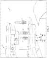
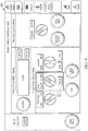
- the material detection system 10 comprises a material detection assembly 14 and a controller 15.
- the material detection assembly 14 is located at or near an input 17 to a machine 13 and includes a plurality of sensors 22, 23, 24 to detect a presence of a material 12 at the input 17 of the machine 13 and to detect properties of the material 12.
- the controller 15 of the machine 13 adjusts at least one parameter of the machine based on a type of the material 12 determined based on at least a portion of the detected properties of the material to prevent damage to the machine 13, and/or allow for changes to occur to the machine or subsequent equipment based on the determination. Stated another way, if the type of material 12 to be processed by the machine 13 is different in the type or grade (type of material and thickness or hardness, respectively) than what the machine is currently setup to run and/or process, the controller 15 adjusts the machine to run the detected material without damage to the machine and/or to increase processing time.
- PLC programmable logic controller
- the change to the machine 13 by the controller 15 occurs via a feedback loop 15a and 15b.
- the feedback loop 15a, 15b provides information from the detection assembly 14 and provides it to the machine 13.
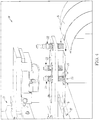
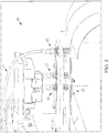
- the machine 13 is found to be any part of an assembly line 400 of additional equipment 402-420.
- the machine 14 is a crimping/punching station.
- the assembly line 400, machine 13, and its equipment 402-420 are used to make the spacer frame for an IGU from coil stock S. The process of making the spacer frame for an IGU, the details of the spacer frame, and operation of the equipment is further discussed in U.S. Patent No. 9,212,515 .
- the assembly line 400 is fed sheet metal stock endwise from the coil stock S into one end of the assembly line and substantially completed elongated window components, e.g., the spacer frame emerges from the other end of the line 400.
- the line 400 comprises a stock supply station 402, the machine 13, a transfer mechanism 405, a first forming station 410, second and third forming stations 414, 416, a conveyor 413, and a scrap removal apparatus 411, respectively, where partially formed spacer frames are separated from the leading end of the stock and frame corner locations are deformed preparatory to being folded into their final configurations, a desiccant application station 419 where desiccant is applied to an interior region of the spacer frame, and an extrusion station 420 where sealant is applied to the yet to be folded spacer frame.
- a scheduler/motion controller unit 15, 422 interacts with the stations and loop feed sensors and the sensors 22, 23, 24 to at least one of govern a spacer stock size, a spacer assembly size, stock feeding speeds in the line, and other parameters involved in production of a window or door spacer frame.
- a preferred controller unit 15, 422 is commercially available from Delta Tau, 21314 Lassen St, Chatsworth, Calif. 91311 as part number UMAC, while it would be appreciated by one of ordinary skill in the art that other types/brands of controllers, CPUs, and/or PLCs could be used.
- the material detection assembly 14 comprises three different sensors: a material present (MP) sensor 22, a material color (MC) sensor 23, and a material type (MT) sensor 24.
- MP material present
- MC material color
- MT material type
- the sensors 22-24 of the material detection system 14 can each detect a different property of the material 12.
- the material 12 can be a thin gauge material (or metal strip "S") used in the fabrication of spacer assemblies for IGUs, such as standard thinplate steel (mild tin plated steel), black thinplate steel (mild tin plated steel painted black), ultra stainless steel, galvanized steel, aluminum, copper, brass, or black ultra stainless steel (stainless steel painted black).
- machine tooling or other parts of the machine 13 and/or equipment 402-420 that are sensitive to the type the material may break if improperly configured, leaving the machine 13 and equipment 402-420 operating at a reduced efficiency or unable to fabricate spacer assemblies correctly, disrupting the window or door-making process.
- the MP sensor 22 detects a presence of the material 12 at the input 17 to the machine 13 (detecting whether or not the material 12 is loaded in the machine 13).
- the MP sensor 22 includes an inductive proximity sensor (e.g ., one commercial embodiment includes an IFM Efector sensor part no. IGC224, manufactured by IFM Efector, Inc., Malvern, PA) that is capable of detecting the presence of all metals within a sensing range.
- the sensing range is variable based on correction factors for different metals listed in Table 1.
- Table 1 Correction factors for different materials.
- Material Approximate Correction Factor Mild Steel 1.0 Stainless Steel 0.85 Brass 0.50 Aluminum 0.45 Copper 0.40
- the MC sensor 23 detects a degree of absorbency or reflectivity of the material 12.
- the MC sensor 23 includes an adjustable diffuse reflective photoelectric sensor (e.g., one commercial embodiment includes an IFM Efector part no. OGT204, manufactured by IFM Efector, Inc., Malvern, PA) that transmits a beam of light onto the material 12 and measures an amount or an intensity of light that is reflected back to the sensor.
- the MC sensor 23 is able to detect a difference in contrast of between different types of material.
- the MC sensor 23 can detect materials that are black and materials that are not black with a high degree of accuracy.
- a black surface will have a reflectivity closer to 0% and an unpainted reflective surface will reflectivity closer to 100% of visible light.
- the point at which the MC sensor 23 transitions between the 0% to 100% state is adjustable based upon the MC sensor's sensitivity setting. As the differential between black and not black in reflected light is large, the MC sensor 23 identifies black and not black with a high degree of accuracy.
- the information detected by the MC sensor 23 can be used to distinguish between standard thinplate steel and black thinplate steel or ultra stainless steel and black ultra stainless steel, since each has a different surface contrast.
- the MT sensor 24 detects a type of the material 12.
- the MP sensor 24 includes a Ferrous only inductive sensor (e.g ., an IFM Efector #IGC 249, IFM Efector, Inc., Malvern, PA), which can determine a difference between mild steel (e.g ., thinplate steel) and stainless steel.
- a Ferrous only sensor the MT sensor 24 is immune to sensing metals with correction factors of about 0.5 or less (shown in Table 1). However, the MT sensor 24 is generally unable to differentiate between ferrous steel and stainless steel with a high degree of accuracy.
- the MT sensor 24 By placing a different material (DM) 25 with a correction factor less than or equal to 0.5 opposed to the MT sensor 24, the MT sensor 24 becomes able to differentiate between mild steel and stainless steel with a high degree of accuracy.
- the MT sensor 24 and the DM 25 can be arranged so that the material 12 is placed between the MT sensor 24 and the DM 25.
- the DM 25 can be any material with a correction factor less than or equal to 0.5, like brass, aluminum, and copper.
- the material can be configured, for example, in the shape of a block or a cylinder or any other shape that allows the DM 25 to be placed in a position opposed to the MT sensor 24.
- the DM 25 is an aluminum block or an aluminum cylinder.
- the MT sensor 24 distinguishes between ferrous steel and stainless steel based on a magnetic field absorbed or not absorbed by the material 12. Ferrous steel absorbs a magnetic field, while stainless steel does not absorb the magnetic field.
- the aluminum DM 25 located behind the material 12 is able to shunt or not shunt the magnetic field, which enables the MT sensor 24 to determine the difference between ferrous steel and stainless steel in the strip S.
- the sensors 22-24 deliver signals to the controller 15 included the respective detected property.
- the MP sensor 22 delivers a signal to the controller 15 indicating whether the material 12 is present at the input 17 to the machine 13.
- the MC sensor 23 delivers a signal to the controller 15 indicating the degree of absorbency or reflectivity of the material 12.
- the MT sensor 24 delivers a signal to the controller indicating a degree of iron or magnetism of the material 12.
- the controller 15 determines the type of material (e.g., copper, steel, etc.) and grade of the material (e.g ., thickness and/or hardness of the material) based on the signals received from the sensors 22-24 to ensure that the machine 13 is properly configured for the material 12.
- the controller 15 determines whether the material 12 is standard thinplate steel (mild tin plated steel), black thinplate steel (mild tin plated steel painted black), ultra stainless steel, black ultra stainless steel (stainless steel painted black), copper, aluminum, or brass based on the properties detected by the sensors 22-24.
- the controller 15 can include safe parameters related to the type of the material that can be used to ensure that the machine 13 and equipment 402-420 is properly configured for the material 12.
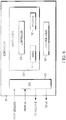
- the controller 15 contains control logic 67 that includes a safety check 63 before allowing the machine 13 to run.
- the safety check 63 may prevent the machine 13 from running while configured for the wrong material.
- the signals from the sensors 22-24 are used as feedback related to the material that is loaded into the machine 13 for the safety check 63 to perform its comparison of the material 12 to the configuration of the control logic 67.
- FIG. 7 An example method 70 of operation of the safety check 63 of the controller 15 is shown in FIG. 7 .
- the controller 15 receives through I/O 62 signals from the sensors 22-24 related to the type of material 12 at the input 17 to the machine 13. From the sensors 22-24, the controller 15 receives information related to the material 12 being present at the input 17 to the machine 13, information related to the degree of absorbency, or reflectivity of the material 12, and information related to the type of the material 12. Using this information, at 73, the controller 15 determines a sensed type of material 12.
- the sensed type of material 12 can be standard thinplate steel (mild tin plated steel), black thinplate steel (mild tin plated steel painted black), ultra stainless steel, copper, brass, aluminum or black ultra stainless steel (stainless steel painted black) determined based on information from the MC sensor 23 and the MT sensor 24.
- the controller 15 receives a configuration signal from the UI 16. This configuration signal is received before, at about the same time, or after the signals are received from the sensors 22-24.
- the configured type of material is determined by the controller 15.
- the comparator 64 of the safety check 63 matches the sensed type of material to the configured type of material. If there is a match between the sensed type of material and the configured type of material, at 77, the control logic 67 allows the machine 13 to proceed with the configuration for the material. The controller 15 communicates at least a portion of the control logic 67 configured as is to the machine 13 through the I/O 62 to control operations of the machine 13 and its components. However, if there is not a match between the sensed type of material and the configured type of material, at 78, the control logic 67 allows the controller 15 to hold the process in order for the configuration to be changed. The controller 15 communicates with the UI 16 through the I/O 62 to undertake the reconfiguration for the sensed type of material. After the configuration is changed, the controller 15 communicates at least a portion of the reconfigured control logic 67 to the machine 13.
- FIGS. 8-11 Different example UIs 16 are shown in FIGS. 8-11 .
- the examples in FIGS. 8-11 correspond to operation of a feeder press.
- Shown in FIG. 8 is a basic operator interface screen 500 allowing selection of the type of material 12 being loaded into the machine 13.
- a selector switch 502 is included to select the material. In this example, an operator moves the selector switch 502 to the left or right to the position corresponding to the material 12 to be entered into the machine 13.
- FIG. 9 shows an example of a different user interface 600 seen by someone who logs in as an Administrator.
- An Administrator has different permissions than a general operator such that the Administrator reconfigures the UI.
- the different user interface 600 will display a setup button 604 in connection with the selector switch 502 such that when the setup button is pressed, another operator interface screen 700 shown in FIG. 10 appears that allows the Administrator to select a number of materials ( e.g ., two) to appear on the operator interface screen 500 of FIG. 8 .
- the materials selected should ultimately match the configuration of the machine 13. For example, die stops that are installed on quick change platens indicate materials that can be used on the machine 13 without damaging the machine.
- FIG. 10 also includes a check box 702 telling the controller 15 to ignore the inputs from the sensors 22-24. For example, the Administrator could check this box in the event that one or more of the materials sensors were to go bad and the machine 13 was still desirous to run the machine.
- FIG. 11 shows an example of an operator interface 800 that is automatically updated with the two materials that are selected by the Administrator. If either of the two material selections fails to match the material 12 that is loaded into the machine 13, a message 802 appears in the top right corner of the operator interface screen 800( see FIG. 11 ) alerting the user of the operator interface and/or the person who loaded the material into the machine. When the message 802 appears on the operator interface screen 800, the machine 13 will also be prevented from running in AUTO mode unless the "ignore material sensors" checkbox 702 is checked or the material type selector is updated to reflect what is actually in the machine 13.
- a material type will be predetermined via a schedule that is downloaded onto the controller 15, rather than being manually selected as indicated in FIGS. 8-11 .
- the schedule is downloaded via a communication port (e.g., a USB port, a signal transceiver, a signal receiver, or the like).
- relational terms such as first and second, top and bottom, and the like may be used solely to distinguish one entity or action from another entity or action without necessarily requiring or implying any actual such relationship or order between such entities or actions.
- the terms “comprises,” “comprising,” “has”, “having,” “includes”, “including,” “contains”, “containing” or any other variation thereof, are intended to cover a non-exclusive inclusion, such that a process, method, article, or apparatus that comprises, has, includes, contains a list of elements does not include only those elements but may include other elements not expressly listed or inherent to such process, method, article, or apparatus.
- processors such as microprocessors, digital signal processors, customized processors and field programmable gate arrays (FPGAs) and unique stored program instructions (including both software and firmware) that control the one or more processors to implement, in conjunction with certain non-processor circuits, some, most, or all of the functions of the method and/or apparatus described herein.
- processors or “processing devices”
- FPGAs field programmable gate arrays
- unique stored program instructions including both software and firmware
- an embodiment can be implemented as a computer-readable storage medium having computer readable code stored thereon for programming a computer (e.g., comprising a processor) to perform a method as described and claimed herein.
- Examples of such computer-readable storage mediums include, but are not limited to, a hard disk, a CD-ROM, an optical storage device, a magnetic storage device, a ROM (Read Only Memory), a PROM (Programmable Read Only Memory), an EPROM (Erasable Programmable Read Only Memory), an EEPROM (Electrically Erasable Programmable Read Only Memory) and a Flash memory.
Landscapes
- Physics & Mathematics (AREA)
- Life Sciences & Earth Sciences (AREA)
- General Physics & Mathematics (AREA)
- Chemical & Material Sciences (AREA)
- Health & Medical Sciences (AREA)
- Pathology (AREA)
- Biochemistry (AREA)
- General Health & Medical Sciences (AREA)
- Immunology (AREA)
- Analytical Chemistry (AREA)
- Spectroscopy & Molecular Physics (AREA)
- Engineering & Computer Science (AREA)
- Remote Sensing (AREA)
- Food Science & Technology (AREA)
- Medicinal Chemistry (AREA)
- Environmental & Geological Engineering (AREA)
- Geology (AREA)
- General Life Sciences & Earth Sciences (AREA)
- Geophysics (AREA)
- Electromagnetism (AREA)
- Investigating Or Analyzing Materials By The Use Of Magnetic Means (AREA)
- Geophysics And Detection Of Objects (AREA)
Claims (13)
- Système comprenant :un système de détection (10) pour détecter une présence d'un matériau métallique d'entrée (12) durant l'utilisation au niveau d'une entrée dans une machine (13) et pour détecter des propriétés du matériau métallique d'entrée, le système de détection comprenant :un capteur de présence de matériau (22) ;un capteur à induction (24) positionné sur un côté d'un chemin d'entrée pour détecter une propriété du matériau métallique d'entrée ;un autre matériau métallique (25), différent dudit matériau métallique d'entrée etpositionné sur un côté opposé audit un côté du chemin d'entrée et opposé au capteur à induction (24) au niveau d'une séparation appropriée pour impacter un signal de capteur à induction sur la base d'une propriété du matériau métallique d'entrée ; dans lequel un facteur de correction de capteur à induction dudit capteur à induction (24) pour ledit autre matériau métallique (25) est 0,5 ou moins ; etun capteur de couleur de matériau (23) ; etun dispositif de commande (15) de la machine (13) pour surveiller un signal provenant du capteur de présence de matériau (22), pour surveiller le signal provenant du capteur à induction (24) et pour surveiller un signal provenant du capteur de couleur de matériau (23) afin d'ajuster au moins un paramètre de la machine (13) sur la base d'un type du matériau métallique d'entrée déterminé à partir des propriétés du matériau métallique d'entrée dans lequel le matériau métallique d'entrée durant l'utilisation est placé entre le capteur à induction (24) et l'autre matériau métallique (25).
- Système selon la revendication 1, dans lequel le capteur de présence de matériau comprend un capteur de proximité à induction (22) configuré pour détecter la présence d'un matériau métallique au niveau du chemin d'entrée dans la machine (13).
- Système selon la revendication 1, dans lequel le matériau métallique d'entrée durant l'utilisation comprend un acier inoxydable ou un acier doux.
- Système selon la revendication 1, dans lequel le capteur à induction (24) est configuré pour détecter une partie d'un champ magnétique non absorbée par le matériau métallique d'entrée.
- Système selon la revendication 1, dans lequel le capteur à induction (24) couple un signal au dispositif de commande (15) et le dispositif de commande (15) fait la distinction entre un acier doux du matériau métallique d'entrée et un acier inoxydable du matériau métallique d'entrée sur la base du signal.
- Système selon la revendication 1, dans lequel l'autre matériau métallique (25) se présente selon une forme d'un bloc ou d'un cylindre et comprend au moins l'un parmi de laiton, de l'aluminium et du cuivre.
- Système selon la revendication 1, dans lequel le capteur de couleur de matériau comprend un capteur photoélectrique réfléchissant diffus (23) configuré pour déterminer au moins l'un parmi un degré de pouvoir absorbant et un degré de réflectivité du matériau métallique d'entrée.
- Système selon la revendication 1, dans lequel le dispositif de commande (15) est programmé pour déterminer le type et la qualité du matériau métallique d'entrée sur la base de signaux reçus en provenance du capteur de présence de matériau, du capteur à induction (22) et du capteur de couleur de matériau (23).
- Système selon la revendication 1, dans lequel le dispositif de commande (15) est programmé pour comparer des paramètres de sécurité liés au type du matériau métallique d'entrée à des paramètres de matériau sélectionnés à partir d'une entrée dans une interface utilisateur graphique (500, 600, 700, 800) pour permettre un changement automatisé pour empêcher la détérioration de la machine (500, 600, 700, 800).
- Système selon la revendication 1 comprenant en outre :au moins l'un parmi une interface utilisateur (500, 600, 700, 800) et un port de communication qui reçoit une sélection du type du matériau métallique d'entrée à charger dans la machine ; etledit dispositif de commande (15) effectue un contrôle de sécurité faisant correspondre le type de matériau sélectionné à un type de matériau déterminé sur la base de signaux reçus depuis une pluralité de capteurs comprenant le capteur de présence de matériau (22), le capteur à induction opposé par l'autre matériau et le capteur de couleur de matériau (23).
- Procédé de détection d'un type d'un matériau métallique d'entrée (12) à traiter par une machine (13), le procédé comprenant les étapes de :fourniture d'un capteur de présence de matériau (22) ;fourniture d'un capteur à induction (24) et positionner le capteur à induction sur un côté d'un chemin d'entrée de matériau pour détecter une propriété du matériau métallique d'entrée ;fourniture d'un matériau métallique différent (25) sur un côté opposé audit un côté du chemin d'entrée et opposé au capteur à induction (24) au niveau d'une séparation appropriée pour impacter un signal de capteur à induction sur la base d'une propriété du matériau métallique d'entrée ;dans lequel un facteur de correction de capteur à induction dudit capteur à induction (24) pour ledit autre métal (25) est de 0,5 ou moins ;fourniture d'un capteur de couleur de matériau (23) ;fourniture d'un dispositif de commande (15) dans la machine (13) ayant une boucle de rétroaction pour ajuster au moins un paramètre de la machine sur la base du type du matériau métallique d'entrée détecté à partir d'un ou plusieurs parmi le capteur de présence de matériau (22), le capteur à induction (22) et le capteur de couleur de matériau (23) ; etfourniture d'un matériau métallique d'entrée à identifier entre le capteur à induction et le matériau métallique différent (25).
- Procédé selon la revendication 11, comprenant en outre au moins l'une des étapes suivantes :la fourniture d'un capteur de proximité à induction configuré pour détecter la présence d'un matériau métallique au niveau de l'entrée dans la machine ;la fourniture d'un capteur photoélectrique réfléchissant diffus qui détermine un contraste du matériau ;la détermination du type et de la qualité du matériau sur la base de signaux reçus en provenance du capteur à induction et du capteur de couleur de matériau ;la fourniture d'au moins l'un parmi le laiton, l'aluminium et le cuivre pour comprendre le matériau différent ;la détection d'une partie d'un champ magnétique non absorbée par le matériau différent pour déterminer le type de matériau ; etla comparaison de paramètres de sécurité liés au type du matériau d'entrée détecté par les capteurs à un matériau sélectionné sur la base de la sélection d'un type de matériau pour permettre un changement pour empêcher la détérioration de la machine.
- Système selon la revendication 1 dans lequel :
le dispositif de commande de la machine inclut une boucle de rétroaction vers la machine, qui effectue un contrôle de sécurité faisant correspondre un type de matériau sélectionné à un type de matériau déterminé sur la base de signaux reçus en provenance des capteurs et sur la base d'un matériau antérieur et différent traité par ladite machine durant l'utilisation, ledit dispositif de commande ajuste au moins un paramètre de la machine sur la base d'un type d'un matériau ultérieur déterminé sur la base des propriétés du matériau ultérieur pour empêcher la détérioration de la machine.
Priority Applications (1)
| Application Number | Priority Date | Filing Date | Title |
|---|---|---|---|
| PL17739041T PL3402627T3 (pl) | 2016-01-14 | 2017-01-13 | System wykrywania materiału |
Applications Claiming Priority (2)
| Application Number | Priority Date | Filing Date | Title |
|---|---|---|---|
| US201662278701P | 2016-01-14 | 2016-01-14 | |
| PCT/US2017/013421 WO2017123936A1 (fr) | 2016-01-14 | 2017-01-13 | Système de détection de matériau |
Publications (3)
| Publication Number | Publication Date |
|---|---|
| EP3402627A1 EP3402627A1 (fr) | 2018-11-21 |
| EP3402627A4 EP3402627A4 (fr) | 2019-08-21 |
| EP3402627B1 true EP3402627B1 (fr) | 2020-10-21 |
Family
ID=59311550
Family Applications (1)
| Application Number | Title | Priority Date | Filing Date |
|---|---|---|---|
| EP17739041.6A Not-in-force EP3402627B1 (fr) | 2016-01-14 | 2017-01-13 | Système de détection de matériau |
Country Status (7)
| Country | Link |
|---|---|
| US (1) | US10156515B2 (fr) |
| EP (1) | EP3402627B1 (fr) |
| CA (1) | CA3032357C (fr) |
| ES (1) | ES2844979T3 (fr) |
| MX (1) | MX2018008728A (fr) |
| PL (1) | PL3402627T3 (fr) |
| WO (1) | WO2017123936A1 (fr) |
Families Citing this family (2)
| Publication number | Priority date | Publication date | Assignee | Title |
|---|---|---|---|---|
| EP3858541B1 (fr) | 2018-09-26 | 2024-08-21 | Dalian University Of Technology | Procédé de perçage de trou automatique à ajustement auto-adaptatif du paramètre d'usinage |
| EP4217119A1 (fr) | 2020-09-28 | 2023-08-02 | Vitro Flat Glass LLC | Dispositif de distribution de matériaux d'étanchéité et son procédés d'utilisation |
Family Cites Families (13)
| Publication number | Priority date | Publication date | Assignee | Title |
|---|---|---|---|---|
| US3889503A (en) * | 1974-07-01 | 1975-06-17 | Verson Allsteel Press Co | Safety indicator system and method for metal forming machines |
| US4400850A (en) * | 1982-03-01 | 1983-08-30 | Herman E. Cox | Foreign object detector for protection of carding machines |
| US5284012A (en) | 1991-05-16 | 1994-02-08 | General Electric Company | Nacelle cooling and ventilation system |
| US6060677A (en) * | 1994-08-19 | 2000-05-09 | Tiedemanns-Jon H. Andresen Ans | Determination of characteristics of material |
| US7610681B2 (en) | 2004-09-29 | 2009-11-03 | Ged Integrated Solutions, Inc. | Window component stock indexing |
| US7674994B1 (en) * | 2004-10-21 | 2010-03-09 | Valerio Thomas A | Method and apparatus for sorting metal |
| CA2647700C (fr) * | 2006-03-31 | 2012-12-11 | Thomas Valerio | Procede et dispositif de tri de metaux non ferreux fins et d'elements de fils metallique isoles |
| US7448246B2 (en) | 2006-05-02 | 2008-11-11 | Ged Integrated Solutions, Inc. | Window frame corner fabrication |
| US8154278B2 (en) * | 2008-01-26 | 2012-04-10 | Pepperl+Fuchs, Inc. | Metal face inductive proximity sensor |
| DE102008049908A1 (de) * | 2008-10-02 | 2010-04-08 | Robert Bosch Gmbh | Verfahren zur Erzeugung eines Detektionssignals und Erfassungseinrichtung |
| RU2561475C2 (ru) * | 2010-03-24 | 2015-08-27 | Рэ-Пэт Лтд | Измельчающее устройство |
| US9765564B2 (en) | 2013-03-14 | 2017-09-19 | Ged Integrated Solutions, Inc. | Automated spacer frame fabrication and method |
| US9082447B1 (en) * | 2014-09-22 | 2015-07-14 | WD Media, LLC | Determining storage media substrate material type |
-
2017
- 2017-01-13 US US15/405,954 patent/US10156515B2/en active Active
- 2017-01-13 MX MX2018008728A patent/MX2018008728A/es unknown
- 2017-01-13 CA CA3032357A patent/CA3032357C/fr active Active
- 2017-01-13 PL PL17739041T patent/PL3402627T3/pl unknown
- 2017-01-13 WO PCT/US2017/013421 patent/WO2017123936A1/fr not_active Ceased
- 2017-01-13 EP EP17739041.6A patent/EP3402627B1/fr not_active Not-in-force
- 2017-01-13 ES ES17739041T patent/ES2844979T3/es active Active
Non-Patent Citations (1)
| Title |
|---|
| None * |
Also Published As
| Publication number | Publication date |
|---|---|
| US20170205334A1 (en) | 2017-07-20 |
| CA3032357A1 (fr) | 2017-07-20 |
| CA3032357C (fr) | 2024-02-27 |
| MX2018008728A (es) | 2018-09-28 |
| EP3402627A4 (fr) | 2019-08-21 |
| US10156515B2 (en) | 2018-12-18 |
| EP3402627A1 (fr) | 2018-11-21 |
| PL3402627T3 (pl) | 2021-04-19 |
| ES2844979T3 (es) | 2021-07-23 |
| WO2017123936A1 (fr) | 2017-07-20 |
Similar Documents
| Publication | Publication Date | Title |
|---|---|---|
| EP3402627B1 (fr) | Système de détection de matériau | |
| EP2969616B1 (fr) | Ensemble fenêtre comprenant une couche transparente électroconductrice | |
| CN109692876B (zh) | 一种月牙剪对带钢冲边的控制方法 | |
| CN216505346U (zh) | 切割装置 | |
| US9965927B2 (en) | Checkout system assembly with goods separator detection | |
| CN103219586A (zh) | 平板天线的自动检测修正调整方法及其系统 | |
| CN111222605B (zh) | 一种rfid标签识别装置 | |
| KR102265698B1 (ko) | 프레스 성형정보를 이용한 품질 데이터 분석 및 레시피 최적화 기법 | |
| CN111153268A (zh) | 入料系统及入料系统的控制方法 | |
| EP3218159B1 (fr) | Procédé de fabrication d'un boudin de matière | |
| CA3102974C (fr) | Système de suivi d’inspection | |
| EP4270572B1 (fr) | Dispositif de coupe de feuille d'électrode et procédé de coupe | |
| CN107813074A (zh) | 一种自动焊接机 | |
| CN208561097U (zh) | 一种载带收卷机构 | |
| CN105500438A (zh) | 用于裁切内衬胎侧复合件的裁切装置和裁切方法 | |
| CN210759174U (zh) | 一种热压斜切装置 | |
| CN210668101U (zh) | 套管输送检测机构及变压器线圈穿管绕线机 | |
| WO2017184236A1 (fr) | Fonctionnement de véhicule automatisé basé sur un déplacement observé d'autres véhicules | |
| KR101137071B1 (ko) | 자동 슬리팅 보정이 이루어지는 플렉시블 플랫 케이블 제조장치 및 이를 이용한 플렉시블 플랫 케이블의 슬리팅 오차 보정방법 | |
| CN113601315B (zh) | 磨边系统的控制方法、控制装置、磨边系统及存储介质 | |
| CN115338670B (zh) | 数控加工方法、装置、设备及系统 | |
| JP2020110982A (ja) | タイヤ用帯状部材の製造方法 | |
| WO2023003706A1 (fr) | Systèmes et procédés de guidage de faisceau adaptatif pour autoroutes | |
| EP3907029A1 (fr) | Système, procédé et produit programme informatique permettant de réduire le risque de manipulation par erreur d'un outil lors du fonctionnement d'une machine | |
| CN222165941U (zh) | 检测装置 |
Legal Events
| Date | Code | Title | Description |
|---|---|---|---|
| STAA | Information on the status of an ep patent application or granted ep patent |
Free format text: STATUS: THE INTERNATIONAL PUBLICATION HAS BEEN MADE |
|
| PUAI | Public reference made under article 153(3) epc to a published international application that has entered the european phase |
Free format text: ORIGINAL CODE: 0009012 |
|
| STAA | Information on the status of an ep patent application or granted ep patent |
Free format text: STATUS: REQUEST FOR EXAMINATION WAS MADE |
|
| 17P | Request for examination filed |
Effective date: 20180807 |
|
| AK | Designated contracting states |
Kind code of ref document: A1 Designated state(s): AL AT BE BG CH CY CZ DE DK EE ES FI FR GB GR HR HU IE IS IT LI LT LU LV MC MK MT NL NO PL PT RO RS SE SI SK SM TR |
|
| AX | Request for extension of the european patent |
Extension state: BA ME |
|
| DAV | Request for validation of the european patent (deleted) | ||
| DAX | Request for extension of the european patent (deleted) | ||
| A4 | Supplementary search report drawn up and despatched |
Effective date: 20190723 |
|
| RIC1 | Information provided on ipc code assigned before grant |
Ipc: G01N 33/20 20190101ALI20190717BHEP Ipc: G01N 27/00 20060101ALI20190717BHEP Ipc: G01N 21/86 20060101ALI20190717BHEP Ipc: B21D 43/00 20060101ALI20190717BHEP Ipc: E06B 3/673 20060101ALN20190717BHEP Ipc: G01N 21/47 20060101ALI20190717BHEP Ipc: G01N 21/25 20060101ALI20190717BHEP Ipc: B23Q 17/20 20060101AFI20190717BHEP |
|
| GRAP | Despatch of communication of intention to grant a patent |
Free format text: ORIGINAL CODE: EPIDOSNIGR1 |
|
| STAA | Information on the status of an ep patent application or granted ep patent |
Free format text: STATUS: GRANT OF PATENT IS INTENDED |
|
| RIC1 | Information provided on ipc code assigned before grant |
Ipc: E06B 3/673 20060101ALN20200417BHEP Ipc: B21D 43/00 20060101ALI20200417BHEP Ipc: G01N 21/25 20060101ALI20200417BHEP Ipc: G01N 27/72 20060101ALN20200417BHEP Ipc: G01N 33/20 20190101ALI20200417BHEP Ipc: G01N 21/47 20060101ALI20200417BHEP Ipc: G01N 21/86 20060101ALI20200417BHEP Ipc: B23Q 17/20 20060101AFI20200417BHEP |
|
| RIC1 | Information provided on ipc code assigned before grant |
Ipc: B21D 43/00 20060101ALI20200428BHEP Ipc: G01N 21/86 20060101ALI20200428BHEP Ipc: E06B 3/673 20060101ALN20200428BHEP Ipc: G01N 33/20 20190101ALI20200428BHEP Ipc: G01N 21/25 20060101ALI20200428BHEP Ipc: G01N 27/72 20060101ALN20200428BHEP Ipc: G01N 21/47 20060101ALI20200428BHEP Ipc: B23Q 17/20 20060101AFI20200428BHEP |
|
| INTG | Intention to grant announced |
Effective date: 20200518 |
|
| GRAS | Grant fee paid |
Free format text: ORIGINAL CODE: EPIDOSNIGR3 |
|
| GRAA | (expected) grant |
Free format text: ORIGINAL CODE: 0009210 |
|
| STAA | Information on the status of an ep patent application or granted ep patent |
Free format text: STATUS: THE PATENT HAS BEEN GRANTED |
|
| AK | Designated contracting states |
Kind code of ref document: B1 Designated state(s): AL AT BE BG CH CY CZ DE DK EE ES FI FR GB GR HR HU IE IS IT LI LT LU LV MC MK MT NL NO PL PT RO RS SE SI SK SM TR |
|
| REG | Reference to a national code |
Ref country code: GB Ref legal event code: FG4D |
|
| REG | Reference to a national code |
Ref country code: CH Ref legal event code: EP |
|
| REG | Reference to a national code |
Ref country code: DE Ref legal event code: R096 Ref document number: 602017025881 Country of ref document: DE |
|
| REG | Reference to a national code |
Ref country code: IE Ref legal event code: FG4D |
|
| REG | Reference to a national code |
Ref country code: AT Ref legal event code: REF Ref document number: 1325355 Country of ref document: AT Kind code of ref document: T Effective date: 20201115 |
|
| PGFP | Annual fee paid to national office [announced via postgrant information from national office to epo] |
Ref country code: FR Payment date: 20201102 Year of fee payment: 5 Ref country code: GB Payment date: 20201102 Year of fee payment: 5 |
|
| REG | Reference to a national code |
Ref country code: AT Ref legal event code: MK05 Ref document number: 1325355 Country of ref document: AT Kind code of ref document: T Effective date: 20201021 |
|
| REG | Reference to a national code |
Ref country code: NL Ref legal event code: MP Effective date: 20201021 |
|
| PG25 | Lapsed in a contracting state [announced via postgrant information from national office to epo] |
Ref country code: RS Free format text: LAPSE BECAUSE OF FAILURE TO SUBMIT A TRANSLATION OF THE DESCRIPTION OR TO PAY THE FEE WITHIN THE PRESCRIBED TIME-LIMIT Effective date: 20201021 Ref country code: PT Free format text: LAPSE BECAUSE OF FAILURE TO SUBMIT A TRANSLATION OF THE DESCRIPTION OR TO PAY THE FEE WITHIN THE PRESCRIBED TIME-LIMIT Effective date: 20210222 Ref country code: NO Free format text: LAPSE BECAUSE OF FAILURE TO SUBMIT A TRANSLATION OF THE DESCRIPTION OR TO PAY THE FEE WITHIN THE PRESCRIBED TIME-LIMIT Effective date: 20210121 Ref country code: GR Free format text: LAPSE BECAUSE OF FAILURE TO SUBMIT A TRANSLATION OF THE DESCRIPTION OR TO PAY THE FEE WITHIN THE PRESCRIBED TIME-LIMIT Effective date: 20210122 Ref country code: FI Free format text: LAPSE BECAUSE OF FAILURE TO SUBMIT A TRANSLATION OF THE DESCRIPTION OR TO PAY THE FEE WITHIN THE PRESCRIBED TIME-LIMIT Effective date: 20201021 |
|
| PGFP | Annual fee paid to national office [announced via postgrant information from national office to epo] |
Ref country code: IE Payment date: 20210105 Year of fee payment: 5 Ref country code: IT Payment date: 20201211 Year of fee payment: 5 |
|
| REG | Reference to a national code |
Ref country code: LT Ref legal event code: MG4D |
|
| PG25 | Lapsed in a contracting state [announced via postgrant information from national office to epo] |
Ref country code: AT Free format text: LAPSE BECAUSE OF FAILURE TO SUBMIT A TRANSLATION OF THE DESCRIPTION OR TO PAY THE FEE WITHIN THE PRESCRIBED TIME-LIMIT Effective date: 20201021 Ref country code: BG Free format text: LAPSE BECAUSE OF FAILURE TO SUBMIT A TRANSLATION OF THE DESCRIPTION OR TO PAY THE FEE WITHIN THE PRESCRIBED TIME-LIMIT Effective date: 20210121 Ref country code: LV Free format text: LAPSE BECAUSE OF FAILURE TO SUBMIT A TRANSLATION OF THE DESCRIPTION OR TO PAY THE FEE WITHIN THE PRESCRIBED TIME-LIMIT Effective date: 20201021 Ref country code: IS Free format text: LAPSE BECAUSE OF FAILURE TO SUBMIT A TRANSLATION OF THE DESCRIPTION OR TO PAY THE FEE WITHIN THE PRESCRIBED TIME-LIMIT Effective date: 20210221 Ref country code: SE Free format text: LAPSE BECAUSE OF FAILURE TO SUBMIT A TRANSLATION OF THE DESCRIPTION OR TO PAY THE FEE WITHIN THE PRESCRIBED TIME-LIMIT Effective date: 20201021 |
|
| PGFP | Annual fee paid to national office [announced via postgrant information from national office to epo] |
Ref country code: DE Payment date: 20210126 Year of fee payment: 5 Ref country code: PL Payment date: 20201204 Year of fee payment: 5 |
|
| PG25 | Lapsed in a contracting state [announced via postgrant information from national office to epo] |
Ref country code: NL Free format text: LAPSE BECAUSE OF FAILURE TO SUBMIT A TRANSLATION OF THE DESCRIPTION OR TO PAY THE FEE WITHIN THE PRESCRIBED TIME-LIMIT Effective date: 20201021 Ref country code: HR Free format text: LAPSE BECAUSE OF FAILURE TO SUBMIT A TRANSLATION OF THE DESCRIPTION OR TO PAY THE FEE WITHIN THE PRESCRIBED TIME-LIMIT Effective date: 20201021 |
|
| REG | Reference to a national code |
Ref country code: DE Ref legal event code: R097 Ref document number: 602017025881 Country of ref document: DE |
|
| REG | Reference to a national code |
Ref country code: ES Ref legal event code: FG2A Ref document number: 2844979 Country of ref document: ES Kind code of ref document: T3 Effective date: 20210723 |
|
| PG25 | Lapsed in a contracting state [announced via postgrant information from national office to epo] |
Ref country code: RO Free format text: LAPSE BECAUSE OF FAILURE TO SUBMIT A TRANSLATION OF THE DESCRIPTION OR TO PAY THE FEE WITHIN THE PRESCRIBED TIME-LIMIT Effective date: 20201021 Ref country code: SK Free format text: LAPSE BECAUSE OF FAILURE TO SUBMIT A TRANSLATION OF THE DESCRIPTION OR TO PAY THE FEE WITHIN THE PRESCRIBED TIME-LIMIT Effective date: 20201021 Ref country code: SM Free format text: LAPSE BECAUSE OF FAILURE TO SUBMIT A TRANSLATION OF THE DESCRIPTION OR TO PAY THE FEE WITHIN THE PRESCRIBED TIME-LIMIT Effective date: 20201021 Ref country code: EE Free format text: LAPSE BECAUSE OF FAILURE TO SUBMIT A TRANSLATION OF THE DESCRIPTION OR TO PAY THE FEE WITHIN THE PRESCRIBED TIME-LIMIT Effective date: 20201021 Ref country code: CZ Free format text: LAPSE BECAUSE OF FAILURE TO SUBMIT A TRANSLATION OF THE DESCRIPTION OR TO PAY THE FEE WITHIN THE PRESCRIBED TIME-LIMIT Effective date: 20201021 Ref country code: LT Free format text: LAPSE BECAUSE OF FAILURE TO SUBMIT A TRANSLATION OF THE DESCRIPTION OR TO PAY THE FEE WITHIN THE PRESCRIBED TIME-LIMIT Effective date: 20201021 |
|
| PLBE | No opposition filed within time limit |
Free format text: ORIGINAL CODE: 0009261 |
|
| STAA | Information on the status of an ep patent application or granted ep patent |
Free format text: STATUS: NO OPPOSITION FILED WITHIN TIME LIMIT |
|
| PG25 | Lapsed in a contracting state [announced via postgrant information from national office to epo] |
Ref country code: DK Free format text: LAPSE BECAUSE OF FAILURE TO SUBMIT A TRANSLATION OF THE DESCRIPTION OR TO PAY THE FEE WITHIN THE PRESCRIBED TIME-LIMIT Effective date: 20201021 Ref country code: MC Free format text: LAPSE BECAUSE OF FAILURE TO SUBMIT A TRANSLATION OF THE DESCRIPTION OR TO PAY THE FEE WITHIN THE PRESCRIBED TIME-LIMIT Effective date: 20201021 |
|
| REG | Reference to a national code |
Ref country code: CH Ref legal event code: PL |
|
| 26N | No opposition filed |
Effective date: 20210722 |
|
| PG25 | Lapsed in a contracting state [announced via postgrant information from national office to epo] |
Ref country code: LU Free format text: LAPSE BECAUSE OF NON-PAYMENT OF DUE FEES Effective date: 20210113 |
|
| REG | Reference to a national code |
Ref country code: BE Ref legal event code: MM Effective date: 20210131 |
|
| PG25 | Lapsed in a contracting state [announced via postgrant information from national office to epo] |
Ref country code: AL Free format text: LAPSE BECAUSE OF FAILURE TO SUBMIT A TRANSLATION OF THE DESCRIPTION OR TO PAY THE FEE WITHIN THE PRESCRIBED TIME-LIMIT Effective date: 20201021 |
|
| PG25 | Lapsed in a contracting state [announced via postgrant information from national office to epo] |
Ref country code: LI Free format text: LAPSE BECAUSE OF NON-PAYMENT OF DUE FEES Effective date: 20210131 Ref country code: CH Free format text: LAPSE BECAUSE OF NON-PAYMENT OF DUE FEES Effective date: 20210131 Ref country code: SI Free format text: LAPSE BECAUSE OF FAILURE TO SUBMIT A TRANSLATION OF THE DESCRIPTION OR TO PAY THE FEE WITHIN THE PRESCRIBED TIME-LIMIT Effective date: 20201021 |
|
| PGFP | Annual fee paid to national office [announced via postgrant information from national office to epo] |
Ref country code: ES Payment date: 20210726 Year of fee payment: 5 |
|
| PG25 | Lapsed in a contracting state [announced via postgrant information from national office to epo] |
Ref country code: IS Free format text: LAPSE BECAUSE OF FAILURE TO SUBMIT A TRANSLATION OF THE DESCRIPTION OR TO PAY THE FEE WITHIN THE PRESCRIBED TIME-LIMIT Effective date: 20210221 |
|
| PG25 | Lapsed in a contracting state [announced via postgrant information from national office to epo] |
Ref country code: BE Free format text: LAPSE BECAUSE OF NON-PAYMENT OF DUE FEES Effective date: 20210131 |
|
| REG | Reference to a national code |
Ref country code: DE Ref legal event code: R119 Ref document number: 602017025881 Country of ref document: DE |
|
| GBPC | Gb: european patent ceased through non-payment of renewal fee |
Effective date: 20220113 |
|
| PG25 | Lapsed in a contracting state [announced via postgrant information from national office to epo] |
Ref country code: GB Free format text: LAPSE BECAUSE OF NON-PAYMENT OF DUE FEES Effective date: 20220113 Ref country code: DE Free format text: LAPSE BECAUSE OF NON-PAYMENT OF DUE FEES Effective date: 20220802 |
|
| PG25 | Lapsed in a contracting state [announced via postgrant information from national office to epo] |
Ref country code: FR Free format text: LAPSE BECAUSE OF NON-PAYMENT OF DUE FEES Effective date: 20220131 |
|
| PG25 | Lapsed in a contracting state [announced via postgrant information from national office to epo] |
Ref country code: IT Free format text: LAPSE BECAUSE OF NON-PAYMENT OF DUE FEES Effective date: 20220113 Ref country code: IE Free format text: LAPSE BECAUSE OF NON-PAYMENT OF DUE FEES Effective date: 20220113 |
|
| REG | Reference to a national code |
Ref country code: ES Ref legal event code: FD2A Effective date: 20230224 |
|
| PG25 | Lapsed in a contracting state [announced via postgrant information from national office to epo] |
Ref country code: ES Free format text: LAPSE BECAUSE OF NON-PAYMENT OF DUE FEES Effective date: 20220114 |
|
| PG25 | Lapsed in a contracting state [announced via postgrant information from national office to epo] |
Ref country code: CY Free format text: LAPSE BECAUSE OF FAILURE TO SUBMIT A TRANSLATION OF THE DESCRIPTION OR TO PAY THE FEE WITHIN THE PRESCRIBED TIME-LIMIT Effective date: 20201021 |
|
| P01 | Opt-out of the competence of the unified patent court (upc) registered |
Effective date: 20230615 |
|
| PG25 | Lapsed in a contracting state [announced via postgrant information from national office to epo] |
Ref country code: HU Free format text: LAPSE BECAUSE OF FAILURE TO SUBMIT A TRANSLATION OF THE DESCRIPTION OR TO PAY THE FEE WITHIN THE PRESCRIBED TIME-LIMIT; INVALID AB INITIO Effective date: 20170113 |
|
| PG25 | Lapsed in a contracting state [announced via postgrant information from national office to epo] |
Ref country code: MK Free format text: LAPSE BECAUSE OF FAILURE TO SUBMIT A TRANSLATION OF THE DESCRIPTION OR TO PAY THE FEE WITHIN THE PRESCRIBED TIME-LIMIT Effective date: 20201021 |
|
| PG25 | Lapsed in a contracting state [announced via postgrant information from national office to epo] |
Ref country code: PL Free format text: LAPSE BECAUSE OF NON-PAYMENT OF DUE FEES Effective date: 20220113 |
|
| PG25 | Lapsed in a contracting state [announced via postgrant information from national office to epo] |
Ref country code: TR Free format text: LAPSE BECAUSE OF FAILURE TO SUBMIT A TRANSLATION OF THE DESCRIPTION OR TO PAY THE FEE WITHIN THE PRESCRIBED TIME-LIMIT Effective date: 20201021 |
|
| PG25 | Lapsed in a contracting state [announced via postgrant information from national office to epo] |
Ref country code: MT Free format text: LAPSE BECAUSE OF FAILURE TO SUBMIT A TRANSLATION OF THE DESCRIPTION OR TO PAY THE FEE WITHIN THE PRESCRIBED TIME-LIMIT Effective date: 20201021 |