EP3402627B1 - Material detection system - Google Patents
Material detection system Download PDFInfo
- Publication number
- EP3402627B1 EP3402627B1 EP17739041.6A EP17739041A EP3402627B1 EP 3402627 B1 EP3402627 B1 EP 3402627B1 EP 17739041 A EP17739041 A EP 17739041A EP 3402627 B1 EP3402627 B1 EP 3402627B1
- Authority
- EP
- European Patent Office
- Prior art keywords
- sensor
- metal material
- machine
- input
- type
- Prior art date
- Legal status (The legal status is an assumption and is not a legal conclusion. Google has not performed a legal analysis and makes no representation as to the accuracy of the status listed.)
- Not-in-force
Links
- 239000000463 material Substances 0.000 title claims description 142
- 238000001514 detection method Methods 0.000 title claims description 22
- 239000007769 metal material Substances 0.000 claims description 32
- 230000001939 inductive effect Effects 0.000 claims description 26
- 238000000034 method Methods 0.000 claims description 24
- 229910001220 stainless steel Inorganic materials 0.000 claims description 22
- 239000010935 stainless steel Substances 0.000 claims description 22
- 229910052782 aluminium Inorganic materials 0.000 claims description 11
- XAGFODPZIPBFFR-UHFFFAOYSA-N aluminium Chemical compound [Al] XAGFODPZIPBFFR-UHFFFAOYSA-N 0.000 claims description 11
- 229910052751 metal Inorganic materials 0.000 claims description 10
- 239000002184 metal Substances 0.000 claims description 10
- 238000012937 correction Methods 0.000 claims description 9
- RYGMFSIKBFXOCR-UHFFFAOYSA-N Copper Chemical compound [Cu] RYGMFSIKBFXOCR-UHFFFAOYSA-N 0.000 claims description 8
- 229910052802 copper Inorganic materials 0.000 claims description 8
- 239000010949 copper Substances 0.000 claims description 8
- 229910001369 Brass Inorganic materials 0.000 claims description 7
- 239000010951 brass Substances 0.000 claims description 7
- 238000002310 reflectometry Methods 0.000 claims description 6
- 229910001209 Low-carbon steel Inorganic materials 0.000 claims description 5
- 230000008859 change Effects 0.000 claims description 4
- 238000004891 communication Methods 0.000 claims description 2
- 238000012544 monitoring process Methods 0.000 claims 3
- 238000000926 separation method Methods 0.000 claims 2
- 230000006698 induction Effects 0.000 claims 1
- 125000006850 spacer group Chemical group 0.000 description 25
- 229910000831 Steel Inorganic materials 0.000 description 21
- 239000010959 steel Substances 0.000 description 21
- 230000008569 process Effects 0.000 description 8
- ATJFFYVFTNAWJD-UHFFFAOYSA-N Tin Chemical compound [Sn] ATJFFYVFTNAWJD-UHFFFAOYSA-N 0.000 description 7
- CWYNVVGOOAEACU-UHFFFAOYSA-N Fe2+ Chemical compound [Fe+2] CWYNVVGOOAEACU-UHFFFAOYSA-N 0.000 description 6
- 230000008901 benefit Effects 0.000 description 6
- 238000003860 storage Methods 0.000 description 6
- 238000004519 manufacturing process Methods 0.000 description 5
- 150000002739 metals Chemical class 0.000 description 5
- 239000002274 desiccant Substances 0.000 description 4
- 238000010586 diagram Methods 0.000 description 4
- 230000006870 function Effects 0.000 description 4
- 239000011521 glass Substances 0.000 description 4
- 238000012545 processing Methods 0.000 description 4
- 230000009471 action Effects 0.000 description 3
- 230000000712 assembly Effects 0.000 description 3
- 238000000429 assembly Methods 0.000 description 3
- 230000007246 mechanism Effects 0.000 description 3
- 230000003287 optical effect Effects 0.000 description 3
- 239000000565 sealant Substances 0.000 description 3
- 239000000758 substrate Substances 0.000 description 3
- XEEYBQQBJWHFJM-UHFFFAOYSA-N Iron Chemical compound [Fe] XEEYBQQBJWHFJM-UHFFFAOYSA-N 0.000 description 2
- 241000872198 Serjania polyphylla Species 0.000 description 2
- 238000012986 modification Methods 0.000 description 2
- 230000004048 modification Effects 0.000 description 2
- 230000003595 spectral effect Effects 0.000 description 2
- 239000010963 304 stainless steel Substances 0.000 description 1
- 229910001335 Galvanized steel Inorganic materials 0.000 description 1
- 229910000589 SAE 304 stainless steel Inorganic materials 0.000 description 1
- 238000013459 approach Methods 0.000 description 1
- 238000003491 array Methods 0.000 description 1
- 238000002788 crimping Methods 0.000 description 1
- 238000013461 design Methods 0.000 description 1
- 238000005516 engineering process Methods 0.000 description 1
- 238000001125 extrusion Methods 0.000 description 1
- -1 galvanized Substances 0.000 description 1
- 239000008397 galvanized steel Substances 0.000 description 1
- 229910052742 iron Inorganic materials 0.000 description 1
- 230000005389 magnetism Effects 0.000 description 1
- 238000004080 punching Methods 0.000 description 1
- 239000012812 sealant material Substances 0.000 description 1
- 230000035945 sensitivity Effects 0.000 description 1
- 238000009751 slip forming Methods 0.000 description 1
- 238000012546 transfer Methods 0.000 description 1
- 230000007704 transition Effects 0.000 description 1
Images


Classifications
-
- G—PHYSICS
- G01—MEASURING; TESTING
- G01N—INVESTIGATING OR ANALYSING MATERIALS BY DETERMINING THEIR CHEMICAL OR PHYSICAL PROPERTIES
- G01N33/00—Investigating or analysing materials by specific methods not covered by groups G01N1/00 - G01N31/00
- G01N33/20—Metals
- G01N33/202—Constituents thereof
- G01N33/2028—Metallic constituents
-
- G—PHYSICS
- G01—MEASURING; TESTING
- G01J—MEASUREMENT OF INTENSITY, VELOCITY, SPECTRAL CONTENT, POLARISATION, PHASE OR PULSE CHARACTERISTICS OF INFRARED, VISIBLE OR ULTRAVIOLET LIGHT; COLORIMETRY; RADIATION PYROMETRY
- G01J3/00—Spectrometry; Spectrophotometry; Monochromators; Measuring colours
- G01J3/46—Measurement of colour; Colour measuring devices, e.g. colorimeters
-
- G—PHYSICS
- G01—MEASURING; TESTING
- G01N—INVESTIGATING OR ANALYSING MATERIALS BY DETERMINING THEIR CHEMICAL OR PHYSICAL PROPERTIES
- G01N21/00—Investigating or analysing materials by the use of optical means, i.e. using sub-millimetre waves, infrared, visible or ultraviolet light
- G01N21/17—Systems in which incident light is modified in accordance with the properties of the material investigated
- G01N21/25—Colour; Spectral properties, i.e. comparison of effect of material on the light at two or more different wavelengths or wavelength bands
- G01N21/251—Colorimeters; Construction thereof
-
- G—PHYSICS
- G01—MEASURING; TESTING
- G01N—INVESTIGATING OR ANALYSING MATERIALS BY DETERMINING THEIR CHEMICAL OR PHYSICAL PROPERTIES
- G01N21/00—Investigating or analysing materials by the use of optical means, i.e. using sub-millimetre waves, infrared, visible or ultraviolet light
- G01N21/17—Systems in which incident light is modified in accordance with the properties of the material investigated
- G01N21/47—Scattering, i.e. diffuse reflection
- G01N21/4738—Diffuse reflection, e.g. also for testing fluids, fibrous materials
- G01N21/474—Details of optical heads therefor, e.g. using optical fibres
-
- G—PHYSICS
- G01—MEASURING; TESTING
- G01N—INVESTIGATING OR ANALYSING MATERIALS BY DETERMINING THEIR CHEMICAL OR PHYSICAL PROPERTIES
- G01N21/00—Investigating or analysing materials by the use of optical means, i.e. using sub-millimetre waves, infrared, visible or ultraviolet light
- G01N21/84—Systems specially adapted for particular applications
- G01N21/86—Investigating moving sheets
-
- G—PHYSICS
- G01—MEASURING; TESTING
- G01V—GEOPHYSICS; GRAVITATIONAL MEASUREMENTS; DETECTING MASSES OR OBJECTS; TAGS
- G01V3/00—Electric or magnetic prospecting or detecting; Measuring magnetic field characteristics of the earth, e.g. declination, deviation
- G01V3/08—Electric or magnetic prospecting or detecting; Measuring magnetic field characteristics of the earth, e.g. declination, deviation operating with magnetic or electric fields produced or modified by objects or geological structures or by detecting devices
- G01V3/10—Electric or magnetic prospecting or detecting; Measuring magnetic field characteristics of the earth, e.g. declination, deviation operating with magnetic or electric fields produced or modified by objects or geological structures or by detecting devices using induction coils
-
- E—FIXED CONSTRUCTIONS
- E06—DOORS, WINDOWS, SHUTTERS, OR ROLLER BLINDS IN GENERAL; LADDERS
- E06B—FIXED OR MOVABLE CLOSURES FOR OPENINGS IN BUILDINGS, VEHICLES, FENCES OR LIKE ENCLOSURES IN GENERAL, e.g. DOORS, WINDOWS, BLINDS, GATES
- E06B3/00—Window sashes, door leaves, or like elements for closing wall or like openings; Layout of fixed or moving closures, e.g. windows in wall or like openings; Features of rigidly-mounted outer frames relating to the mounting of wing frames
- E06B3/66—Units comprising two or more parallel glass or like panes permanently secured together
- E06B3/673—Assembling the units
-
- G—PHYSICS
- G01—MEASURING; TESTING
- G01N—INVESTIGATING OR ANALYSING MATERIALS BY DETERMINING THEIR CHEMICAL OR PHYSICAL PROPERTIES
- G01N21/00—Investigating or analysing materials by the use of optical means, i.e. using sub-millimetre waves, infrared, visible or ultraviolet light
- G01N21/84—Systems specially adapted for particular applications
- G01N21/86—Investigating moving sheets
- G01N2021/8609—Optical head specially adapted
-
- G—PHYSICS
- G01—MEASURING; TESTING
- G01N—INVESTIGATING OR ANALYSING MATERIALS BY DETERMINING THEIR CHEMICAL OR PHYSICAL PROPERTIES
- G01N27/00—Investigating or analysing materials by the use of electric, electrochemical, or magnetic means
- G01N27/72—Investigating or analysing materials by the use of electric, electrochemical, or magnetic means by investigating magnetic variables
Definitions
- the present disclosure relates to a material detection system and more specifically to a control method that uses the material detection system to determine a type of material at a machine input to prevent damage to the machine and/or allow for changes to occur to the machine or subsequent equipment based on the determination.
- IGUs Insulating glass units
- the spacer assembly usually comprises a frame structure extending peripherally about the unit, a sealant material adhered both to the glass Sites and the frame structure, and a desiccant for absorbing atmospheric moisture within the unit.
- the margins or the glass lites are flush with or extend slightly outwardly from the spacer assembly,
- the sealant extends continuously about the frame structure periphery and its opposite sides so that the space within the IGUs is hermetic.
- U.S. Patent No. 5,361,476 to Leopold discloses a method and apparatus for making IGUs wherein a thin flat strip of sheet material is continuously formed into a channel shaped spacer frame having corner structures and end structures, the spacer thus formed is cut off, sealant and desiccant are applied and the assemblage is bent to form a spacer assembly.
- U.S. Patent No. 7,610,681 to Calcei et al. concerns spacer frame manufacturing equipment wherein a stock supply station includes a number of rotatable sheet stock coils, an indexing mechanism for positioning one of the coils and an uncoiling mechanism. Multiple other processing stations act on the elongated strip of sheet stock uncoiled from the stock supply station.
- U. S. Patent No. 7,448,246 to Briese et al. concerns another spacer frame manufacturing system.
- spacer frames depicted are initially formed as a continuous straight channel constructed from a thin ribbon of stainless steel material e.g ., 304 stainless steel having a thickness of .006 - 0.010 inches.
- other materials such as galvanized, tin plated steel, or aluminum can be used to construct the spacer frame.
- the '246 patent to Briese et al. is also incorporated herein by reference. Typical thickness for these other materials range from .006 to .025 inches in thickness.
- U.S. Patent US 9,082,447 B1 states systems and methods for determining whether a storage media substrate is of a metallic type, wherein the systems comprise an inductive sensor, a sensor indicating the presence of a storage media substrate, and other sensors to provide additional information to distinguish at least two types of media substrates.
- U.S. Patent 7,674,994 B1 describes a system for sorting metals from a batch of mixed material scrap, wherein the system comprises an array of inductive proximity sensors to identify the location of metal pieces.
- the system may also comprise an optical system to detect and sort stainless steel from other types of metals.
- WO 2010/037454 A1 describes generating a detection signal from a processing material, e.g. a metal, by means of a light source, and detecting reflected light by means of an optical sensor device, wherein the detected light is split into at least two spectral ranges, wherein the intensity of each spectral range is determined, in order to generate at least two color signals.
- a processing material e.g. a metal
- One aspect of the present disclosure comprises a system including a material detection system to detect a presence of an input metal material during use at an input to a machine and to detect properties of the input metal material according to claim 1.
- Another aspect of the present disclosure comprises a method of detecting a type of an input metal material to be processed by a machine according to claim 11.
- Another aspect of the present disclosure comprises a system of claim 1, wherein the controller comprised therein includes a feedback loop to the machine, which performs a safety check matching a selected material type to a material type determined based on signals received from the sensors and based upon a prior and different material processed by said machine during use and adjusts at least one parameter of the machine based on a type of a subsequent material determined based on the properties of the subsequent material to prevent damage to the machine.
- the present disclosure relates to a material detection system that can be employed by a controller to determine a type of material at a machine input to prevent damage to the machine, or allow the changes to occur to the machine or subsequent equipment based on the determination.
- the material detection system 10 comprises a material detection assembly 14 and a controller 15.
- the material detection assembly 14 is located at or near an input 17 to a machine 13 and includes a plurality of sensors 22, 23, 24 to detect a presence of a material 12 at the input 17 of the machine 13 and to detect properties of the material 12.
- the controller 15 of the machine 13 adjusts at least one parameter of the machine based on a type of the material 12 determined based on at least a portion of the detected properties of the material to prevent damage to the machine 13, and/or allow for changes to occur to the machine or subsequent equipment based on the determination. Stated another way, if the type of material 12 to be processed by the machine 13 is different in the type or grade (type of material and thickness or hardness, respectively) than what the machine is currently setup to run and/or process, the controller 15 adjusts the machine to run the detected material without damage to the machine and/or to increase processing time.
- PLC programmable logic controller
- the change to the machine 13 by the controller 15 occurs via a feedback loop 15a and 15b.
- the feedback loop 15a, 15b provides information from the detection assembly 14 and provides it to the machine 13.
- the machine 13 is found to be any part of an assembly line 400 of additional equipment 402-420.
- the machine 14 is a crimping/punching station.
- the assembly line 400, machine 13, and its equipment 402-420 are used to make the spacer frame for an IGU from coil stock S. The process of making the spacer frame for an IGU, the details of the spacer frame, and operation of the equipment is further discussed in U.S. Patent No. 9,212,515 .
- the assembly line 400 is fed sheet metal stock endwise from the coil stock S into one end of the assembly line and substantially completed elongated window components, e.g., the spacer frame emerges from the other end of the line 400.
- the line 400 comprises a stock supply station 402, the machine 13, a transfer mechanism 405, a first forming station 410, second and third forming stations 414, 416, a conveyor 413, and a scrap removal apparatus 411, respectively, where partially formed spacer frames are separated from the leading end of the stock and frame corner locations are deformed preparatory to being folded into their final configurations, a desiccant application station 419 where desiccant is applied to an interior region of the spacer frame, and an extrusion station 420 where sealant is applied to the yet to be folded spacer frame.
- a scheduler/motion controller unit 15, 422 interacts with the stations and loop feed sensors and the sensors 22, 23, 24 to at least one of govern a spacer stock size, a spacer assembly size, stock feeding speeds in the line, and other parameters involved in production of a window or door spacer frame.
- a preferred controller unit 15, 422 is commercially available from Delta Tau, 21314 Lassen St, Chatsworth, Calif. 91311 as part number UMAC, while it would be appreciated by one of ordinary skill in the art that other types/brands of controllers, CPUs, and/or PLCs could be used.
- the material detection assembly 14 comprises three different sensors: a material present (MP) sensor 22, a material color (MC) sensor 23, and a material type (MT) sensor 24.
- MP material present
- MC material color
- MT material type
- the sensors 22-24 of the material detection system 14 can each detect a different property of the material 12.
- the material 12 can be a thin gauge material (or metal strip "S") used in the fabrication of spacer assemblies for IGUs, such as standard thinplate steel (mild tin plated steel), black thinplate steel (mild tin plated steel painted black), ultra stainless steel, galvanized steel, aluminum, copper, brass, or black ultra stainless steel (stainless steel painted black).
- machine tooling or other parts of the machine 13 and/or equipment 402-420 that are sensitive to the type the material may break if improperly configured, leaving the machine 13 and equipment 402-420 operating at a reduced efficiency or unable to fabricate spacer assemblies correctly, disrupting the window or door-making process.
- the MP sensor 22 detects a presence of the material 12 at the input 17 to the machine 13 (detecting whether or not the material 12 is loaded in the machine 13).
- the MP sensor 22 includes an inductive proximity sensor (e.g ., one commercial embodiment includes an IFM Efector sensor part no. IGC224, manufactured by IFM Efector, Inc., Malvern, PA) that is capable of detecting the presence of all metals within a sensing range.
- the sensing range is variable based on correction factors for different metals listed in Table 1.
- Table 1 Correction factors for different materials.
- Material Approximate Correction Factor Mild Steel 1.0 Stainless Steel 0.85 Brass 0.50 Aluminum 0.45 Copper 0.40
- the MC sensor 23 detects a degree of absorbency or reflectivity of the material 12.
- the MC sensor 23 includes an adjustable diffuse reflective photoelectric sensor (e.g., one commercial embodiment includes an IFM Efector part no. OGT204, manufactured by IFM Efector, Inc., Malvern, PA) that transmits a beam of light onto the material 12 and measures an amount or an intensity of light that is reflected back to the sensor.
- the MC sensor 23 is able to detect a difference in contrast of between different types of material.
- the MC sensor 23 can detect materials that are black and materials that are not black with a high degree of accuracy.
- a black surface will have a reflectivity closer to 0% and an unpainted reflective surface will reflectivity closer to 100% of visible light.
- the point at which the MC sensor 23 transitions between the 0% to 100% state is adjustable based upon the MC sensor's sensitivity setting. As the differential between black and not black in reflected light is large, the MC sensor 23 identifies black and not black with a high degree of accuracy.
- the information detected by the MC sensor 23 can be used to distinguish between standard thinplate steel and black thinplate steel or ultra stainless steel and black ultra stainless steel, since each has a different surface contrast.
- the MT sensor 24 detects a type of the material 12.
- the MP sensor 24 includes a Ferrous only inductive sensor (e.g ., an IFM Efector #IGC 249, IFM Efector, Inc., Malvern, PA), which can determine a difference between mild steel (e.g ., thinplate steel) and stainless steel.
- a Ferrous only sensor the MT sensor 24 is immune to sensing metals with correction factors of about 0.5 or less (shown in Table 1). However, the MT sensor 24 is generally unable to differentiate between ferrous steel and stainless steel with a high degree of accuracy.
- the MT sensor 24 By placing a different material (DM) 25 with a correction factor less than or equal to 0.5 opposed to the MT sensor 24, the MT sensor 24 becomes able to differentiate between mild steel and stainless steel with a high degree of accuracy.
- the MT sensor 24 and the DM 25 can be arranged so that the material 12 is placed between the MT sensor 24 and the DM 25.
- the DM 25 can be any material with a correction factor less than or equal to 0.5, like brass, aluminum, and copper.
- the material can be configured, for example, in the shape of a block or a cylinder or any other shape that allows the DM 25 to be placed in a position opposed to the MT sensor 24.
- the DM 25 is an aluminum block or an aluminum cylinder.
- the MT sensor 24 distinguishes between ferrous steel and stainless steel based on a magnetic field absorbed or not absorbed by the material 12. Ferrous steel absorbs a magnetic field, while stainless steel does not absorb the magnetic field.
- the aluminum DM 25 located behind the material 12 is able to shunt or not shunt the magnetic field, which enables the MT sensor 24 to determine the difference between ferrous steel and stainless steel in the strip S.
- the sensors 22-24 deliver signals to the controller 15 included the respective detected property.
- the MP sensor 22 delivers a signal to the controller 15 indicating whether the material 12 is present at the input 17 to the machine 13.
- the MC sensor 23 delivers a signal to the controller 15 indicating the degree of absorbency or reflectivity of the material 12.
- the MT sensor 24 delivers a signal to the controller indicating a degree of iron or magnetism of the material 12.
- the controller 15 determines the type of material (e.g., copper, steel, etc.) and grade of the material (e.g ., thickness and/or hardness of the material) based on the signals received from the sensors 22-24 to ensure that the machine 13 is properly configured for the material 12.
- the controller 15 determines whether the material 12 is standard thinplate steel (mild tin plated steel), black thinplate steel (mild tin plated steel painted black), ultra stainless steel, black ultra stainless steel (stainless steel painted black), copper, aluminum, or brass based on the properties detected by the sensors 22-24.
- the controller 15 can include safe parameters related to the type of the material that can be used to ensure that the machine 13 and equipment 402-420 is properly configured for the material 12.
- the controller 15 contains control logic 67 that includes a safety check 63 before allowing the machine 13 to run.
- the safety check 63 may prevent the machine 13 from running while configured for the wrong material.
- the signals from the sensors 22-24 are used as feedback related to the material that is loaded into the machine 13 for the safety check 63 to perform its comparison of the material 12 to the configuration of the control logic 67.
- FIG. 7 An example method 70 of operation of the safety check 63 of the controller 15 is shown in FIG. 7 .
- the controller 15 receives through I/O 62 signals from the sensors 22-24 related to the type of material 12 at the input 17 to the machine 13. From the sensors 22-24, the controller 15 receives information related to the material 12 being present at the input 17 to the machine 13, information related to the degree of absorbency, or reflectivity of the material 12, and information related to the type of the material 12. Using this information, at 73, the controller 15 determines a sensed type of material 12.
- the sensed type of material 12 can be standard thinplate steel (mild tin plated steel), black thinplate steel (mild tin plated steel painted black), ultra stainless steel, copper, brass, aluminum or black ultra stainless steel (stainless steel painted black) determined based on information from the MC sensor 23 and the MT sensor 24.
- the controller 15 receives a configuration signal from the UI 16. This configuration signal is received before, at about the same time, or after the signals are received from the sensors 22-24.
- the configured type of material is determined by the controller 15.
- the comparator 64 of the safety check 63 matches the sensed type of material to the configured type of material. If there is a match between the sensed type of material and the configured type of material, at 77, the control logic 67 allows the machine 13 to proceed with the configuration for the material. The controller 15 communicates at least a portion of the control logic 67 configured as is to the machine 13 through the I/O 62 to control operations of the machine 13 and its components. However, if there is not a match between the sensed type of material and the configured type of material, at 78, the control logic 67 allows the controller 15 to hold the process in order for the configuration to be changed. The controller 15 communicates with the UI 16 through the I/O 62 to undertake the reconfiguration for the sensed type of material. After the configuration is changed, the controller 15 communicates at least a portion of the reconfigured control logic 67 to the machine 13.
- FIGS. 8-11 Different example UIs 16 are shown in FIGS. 8-11 .
- the examples in FIGS. 8-11 correspond to operation of a feeder press.
- Shown in FIG. 8 is a basic operator interface screen 500 allowing selection of the type of material 12 being loaded into the machine 13.
- a selector switch 502 is included to select the material. In this example, an operator moves the selector switch 502 to the left or right to the position corresponding to the material 12 to be entered into the machine 13.
- FIG. 9 shows an example of a different user interface 600 seen by someone who logs in as an Administrator.
- An Administrator has different permissions than a general operator such that the Administrator reconfigures the UI.
- the different user interface 600 will display a setup button 604 in connection with the selector switch 502 such that when the setup button is pressed, another operator interface screen 700 shown in FIG. 10 appears that allows the Administrator to select a number of materials ( e.g ., two) to appear on the operator interface screen 500 of FIG. 8 .
- the materials selected should ultimately match the configuration of the machine 13. For example, die stops that are installed on quick change platens indicate materials that can be used on the machine 13 without damaging the machine.
- FIG. 10 also includes a check box 702 telling the controller 15 to ignore the inputs from the sensors 22-24. For example, the Administrator could check this box in the event that one or more of the materials sensors were to go bad and the machine 13 was still desirous to run the machine.
- FIG. 11 shows an example of an operator interface 800 that is automatically updated with the two materials that are selected by the Administrator. If either of the two material selections fails to match the material 12 that is loaded into the machine 13, a message 802 appears in the top right corner of the operator interface screen 800( see FIG. 11 ) alerting the user of the operator interface and/or the person who loaded the material into the machine. When the message 802 appears on the operator interface screen 800, the machine 13 will also be prevented from running in AUTO mode unless the "ignore material sensors" checkbox 702 is checked or the material type selector is updated to reflect what is actually in the machine 13.
- a material type will be predetermined via a schedule that is downloaded onto the controller 15, rather than being manually selected as indicated in FIGS. 8-11 .
- the schedule is downloaded via a communication port (e.g., a USB port, a signal transceiver, a signal receiver, or the like).
- relational terms such as first and second, top and bottom, and the like may be used solely to distinguish one entity or action from another entity or action without necessarily requiring or implying any actual such relationship or order between such entities or actions.
- the terms “comprises,” “comprising,” “has”, “having,” “includes”, “including,” “contains”, “containing” or any other variation thereof, are intended to cover a non-exclusive inclusion, such that a process, method, article, or apparatus that comprises, has, includes, contains a list of elements does not include only those elements but may include other elements not expressly listed or inherent to such process, method, article, or apparatus.
- processors such as microprocessors, digital signal processors, customized processors and field programmable gate arrays (FPGAs) and unique stored program instructions (including both software and firmware) that control the one or more processors to implement, in conjunction with certain non-processor circuits, some, most, or all of the functions of the method and/or apparatus described herein.
- processors or “processing devices”
- FPGAs field programmable gate arrays
- unique stored program instructions including both software and firmware
- an embodiment can be implemented as a computer-readable storage medium having computer readable code stored thereon for programming a computer (e.g., comprising a processor) to perform a method as described and claimed herein.
- Examples of such computer-readable storage mediums include, but are not limited to, a hard disk, a CD-ROM, an optical storage device, a magnetic storage device, a ROM (Read Only Memory), a PROM (Programmable Read Only Memory), an EPROM (Erasable Programmable Read Only Memory), an EEPROM (Electrically Erasable Programmable Read Only Memory) and a Flash memory.
Landscapes
- Physics & Mathematics (AREA)
- Life Sciences & Earth Sciences (AREA)
- General Physics & Mathematics (AREA)
- Chemical & Material Sciences (AREA)
- Health & Medical Sciences (AREA)
- Pathology (AREA)
- Biochemistry (AREA)
- General Health & Medical Sciences (AREA)
- Immunology (AREA)
- Analytical Chemistry (AREA)
- Spectroscopy & Molecular Physics (AREA)
- Engineering & Computer Science (AREA)
- Remote Sensing (AREA)
- Food Science & Technology (AREA)
- Medicinal Chemistry (AREA)
- Environmental & Geological Engineering (AREA)
- Geology (AREA)
- General Life Sciences & Earth Sciences (AREA)
- Geophysics (AREA)
- Electromagnetism (AREA)
- Investigating Or Analyzing Materials By The Use Of Magnetic Means (AREA)
- Geophysics And Detection Of Objects (AREA)
Description
- The present application claims priority to
U.S. Provisional Patent Application Serial No. 62/278,701 filed January 14, 2016 - The present disclosure relates to a material detection system and more specifically to a control method that uses the material detection system to determine a type of material at a machine input to prevent damage to the machine and/or allow for changes to occur to the machine or subsequent equipment based on the determination.
- Insulating glass units (IGUs) are used in windows to reduce heat loss from building interiors during cold weather. IGUs are typically formed by a spacer assembly sandwiched between glass lites. The spacer assembly usually comprises a frame structure extending peripherally about the unit, a sealant material adhered both to the glass Sites and the frame structure, and a desiccant for absorbing atmospheric moisture within the unit. The margins or the glass lites are flush with or extend slightly outwardly from the spacer assembly, The sealant extends continuously about the frame structure periphery and its opposite sides so that the space within the IGUs is hermetic.
-
U.S. Patent No. 5,361,476 to Leopold discloses a method and apparatus for making IGUs wherein a thin flat strip of sheet material is continuously formed into a channel shaped spacer frame having corner structures and end structures, the spacer thus formed is cut off, sealant and desiccant are applied and the assemblage is bent to form a spacer assembly. -
U.S. Patent No. 7,610,681 to Calcei et al. concerns spacer frame manufacturing equipment wherein a stock supply station includes a number of rotatable sheet stock coils, an indexing mechanism for positioning one of the coils and an uncoiling mechanism. Multiple other processing stations act on the elongated strip of sheet stock uncoiled from the stock supply station. -
U. S. Patent No. 7,448,246 to Briese et al. concerns another spacer frame manufacturing system. As discussed in the '246 patent, spacer frames depicted are initially formed as a continuous straight channel constructed from a thin ribbon of stainless steel material e.g., 304 stainless steel having a thickness of .006 - 0.010 inches. As noted, other materials such as galvanized, tin plated steel, or aluminum can be used to construct the spacer frame. The '246 patent to Briese et al. is also incorporated herein by reference. Typical thickness for these other materials range from .006 to .025 inches in thickness. -
U.S. Patent Publication No. 2014/0260491 entitled Automated Spacer Frame and Fabrication that published on September 18, 2014 and is assigned to the assignee of the present application teaches, inter alia, stop assemblies that require changing based on the type of material being used to form a spacer frame from a supply station. -
U.S. Patent US 9,082,447 B1 -
U.S. Patent 7,674,994 B1 describes a system for sorting metals from a batch of mixed material scrap, wherein the system comprises an array of inductive proximity sensors to identify the location of metal pieces. The system may also comprise an optical system to detect and sort stainless steel from other types of metals. -
WO 2010/037454 A1 describes generating a detection signal from a processing material, e.g. a metal, by means of a light source, and detecting reflected light by means of an optical sensor device, wherein the detected light is split into at least two spectral ranges, wherein the intensity of each spectral range is determined, in order to generate at least two color signals. - One aspect of the present disclosure comprises a system including a material detection system to detect a presence of an input metal material during use at an input to a machine and to detect properties of the input metal material according to
claim 1. - Another aspect of the present disclosure comprises a method of detecting a type of an input metal material to be processed by a machine according to claim 11.
- Another aspect of the present disclosure comprises a system of
claim 1, wherein the controller comprised therein includes a feedback loop to the machine, which performs a safety check matching a selected material type to a material type determined based on signals received from the sensors and based upon a prior and different material processed by said machine during use and adjusts at least one parameter of the machine based on a type of a subsequent material determined based on the properties of the subsequent material to prevent damage to the machine. - The foregoing and other features and advantages of the present disclosure will become apparent to one skilled in the art to which the present disclosure relates upon consideration of the following description of the disclosure with reference to the accompanying drawings, wherein like reference numerals, unless 5 otherwise described refer to like parts throughout the drawings and in which:
-
FIG. 1 is a block diagram of a material detection system constructed in accordance with one example embodiment of the present disclosure; -
FIG. 2 is a block diagram of an example material detection assembly that is used in the system shown inFIG. 1 ; -
FIG. 3 is an illustration of a partially exploded view of an example material detection assembly used in the system shown inFIG. 1 ; -
FIG. 4 is an illustration of a partially assembled example material detection assembly used in the system shown inFIG. 1 wherein a material is partially omitted; -
FIG. 5 is an illustration of an assembled example material detection assembly used in the system shown inFIG. 1 ; -
FIG. 6 is a block diagram of an example controller used in the system shown inFIG. 1 ; -
FIG. 7 is a process flow diagram of an example method for facilitating the operation of a machine based on determining a material present that can be implemented by the controller shown inFIG. 6 ; -
FIG. 8 illustrates a first example user interface screen that can be configured and used by the system shown inFIG. 1 ; -
FIG. 9 illustrates a second example user interface screen that can be configured and used by the system shown inFIG. 1 ; -
FIG. 10 illustrates a third example user interface screen that can be configured and used by the system shown inFIG. 1 ; -
FIG. 11 illustrates a fourth example user interface screen that can be configured and used by the system shown inFIG. 1 ; and -
FIG. 12 illustrates equipment in an assembly line for making a spacer frame. - Skilled artisans will appreciate that elements in the figures are illustrated for simplicity and clarity and have not necessarily been drawn to scale. For example, the dimensions of some of the elements in the figures may be exaggerated relative to other elements to help to improve understanding of the example embodiments of the present disclosure.
- The apparatus, system, and method components have been represented where appropriate by conventional symbols in the drawings, showing only those specific details that are pertinent to understanding the example embodiments of the present disclosure so as not to obscure the disclosure with details that will be readily apparent to those of ordinary skill in the art having the benefit of the description herein.
- Referring now to the figures generally wherein like numbered features shown therein refer to like elements having similar characteristics and operational properties throughout unless otherwise noted. The present disclosure relates to a material detection system that can be employed by a controller to determine a type of material at a machine input to prevent damage to the machine, or allow the changes to occur to the machine or subsequent equipment based on the determination.
- Illustrated in
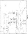
FIG. 1 is a material detection system 10 constructed in accordance with one example embodiment of the present disclosure. In the illustrated example embodiment, the material detection system 10 comprises amaterial detection assembly 14 and acontroller 15. Thematerial detection assembly 14 is located at or near aninput 17 to amachine 13 and includes a plurality ofsensors material 12 at theinput 17 of themachine 13 and to detect properties of thematerial 12. Thecontroller 15 of the machine 13 (e.g., a programmable logic controller (PLC) or similar device) adjusts at least one parameter of the machine based on a type of thematerial 12 determined based on at least a portion of the detected properties of the material to prevent damage to themachine 13, and/or allow for changes to occur to the machine or subsequent equipment based on the determination. Stated another way, if the type ofmaterial 12 to be processed by themachine 13 is different in the type or grade (type of material and thickness or hardness, respectively) than what the machine is currently setup to run and/or process, thecontroller 15 adjusts the machine to run the detected material without damage to the machine and/or to increase processing time. - In one example embodiment, the change to the
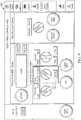
machine 13 by thecontroller 15 occurs via a feedback loop 15a and 15b. The feedback loop 15a, 15b provides information from thedetection assembly 14 and provides it to themachine 13. InFIG. 12 , themachine 13 is found to be any part of anassembly line 400 of additional equipment 402-420. However, in the illustrated example embodiment, themachine 14 is a crimping/punching station. Theassembly line 400,machine 13, and its equipment 402-420 are used to make the spacer frame for an IGU from coil stock S. The process of making the spacer frame for an IGU, the details of the spacer frame, and operation of the equipment is further discussed inU.S. Patent No. 9,212,515 assembly line 400 is fed sheet metal stock endwise from the coil stock S into one end of the assembly line and substantially completed elongated window components, e.g., the spacer frame emerges from the other end of theline 400. - The
line 400 comprises astock supply station 402, themachine 13, atransfer mechanism 405, a first formingstation 410, second and third forming stations 414, 416, aconveyor 413, and ascrap removal apparatus 411, respectively, where partially formed spacer frames are separated from the leading end of the stock and frame corner locations are deformed preparatory to being folded into their final configurations, adesiccant application station 419 where desiccant is applied to an interior region of the spacer frame, and anextrusion station 420 where sealant is applied to the yet to be folded spacer frame. A scheduler/motion controller unit 15, 422 interacts with the stations and loop feed sensors and thesensors controller unit 15, 422 is commercially available from Delta Tau, 21314 Lassen St, Chatsworth, Calif. 91311 as part number UMAC, while it would be appreciated by one of ordinary skill in the art that other types/brands of controllers, CPUs, and/or PLCs could be used. - In an example shown in
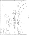
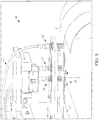
FIGS. 2-5 , thematerial detection assembly 14 comprises three different sensors: a material present (MP)sensor 22, a material color (MC)sensor 23, and a material type (MT)sensor 24. Although thematerial detection assembly 14 shown inFIGS. 2-5 are configured with the sensors arranged so that thematerial 12 first encounters theMP sensor 22, then theMC sensor 23, and then theMT sensor 24, it will be apparent that theMC sensor 23 and theMT sensor 24 may be arranged in any order, as long asmaterial 12 encounters theMP sensor 22 first. - The sensors 22-24 of the
material detection system 14 can each detect a different property of thematerial 12. In one example, thematerial 12 can be a thin gauge material (or metal strip "S") used in the fabrication of spacer assemblies for IGUs, such as standard thinplate steel (mild tin plated steel), black thinplate steel (mild tin plated steel painted black), ultra stainless steel, galvanized steel, aluminum, copper, brass, or black ultra stainless steel (stainless steel painted black). If not properly configured for thematerial 12, machine tooling or other parts of themachine 13 and/or equipment 402-420 that are sensitive to the type thematerial 12,may break if improperly configured, leaving themachine 13 and equipment 402-420 operating at a reduced efficiency or unable to fabricate spacer assemblies correctly, disrupting the window or door-making process. - The
MP sensor 22 detects a presence of the material 12 at theinput 17 to the machine 13 (detecting whether or not the material 12 is loaded in the machine 13). In one example embodiment, theMP sensor 22 includes an inductive proximity sensor (e.g., one commercial embodiment includes an IFM Efector sensor part no. IGC224, manufactured by IFM Efector, Inc., Malvern, PA) that is capable of detecting the presence of all metals within a sensing range. The sensing range of the inductive proximity sensor can be expressed as follows:
- As shown in
Equation 1, the sensing range is variable based on correction factors for different metals listed in Table 1.Table 1 - Correction factors for different materials. Material Approximate Correction Factor Mild Steel 1.0 Stainless Steel 0.85 Brass 0.50 Aluminum 0.45 Copper 0.40 - The
MC sensor 23 detects a degree of absorbency or reflectivity of thematerial 12. In one example embodiment, theMC sensor 23 includes an adjustable diffuse reflective photoelectric sensor (e.g., one commercial embodiment includes an IFM Efector part no. OGT204, manufactured by IFM Efector, Inc., Malvern, PA) that transmits a beam of light onto thematerial 12 and measures an amount or an intensity of light that is reflected back to the sensor. Accordingly, theMC sensor 23 is able to detect a difference in contrast of between different types of material. For example, theMC sensor 23 can detect materials that are black and materials that are not black with a high degree of accuracy. Stated another way, a black surface will have a reflectivity closer to 0% and an unpainted reflective surface will reflectivity closer to 100% of visible light. The point at which theMC sensor 23 transitions between the 0% to 100% state is adjustable based upon the MC sensor's sensitivity setting. As the differential between black and not black in reflected light is large, theMC sensor 23 identifies black and not black with a high degree of accuracy. The information detected by theMC sensor 23 can be used to distinguish between standard thinplate steel and black thinplate steel or ultra stainless steel and black ultra stainless steel, since each has a different surface contrast. - The
MT sensor 24 detects a type of thematerial 12. For example, theMP sensor 24 includes a Ferrous only inductive sensor (e.g., an IFM Efector #IGC 249, IFM Efector, Inc., Malvern, PA), which can determine a difference between mild steel (e.g., thinplate steel) and stainless steel. As a Ferrous only sensor, theMT sensor 24 is immune to sensing metals with correction factors of about 0.5 or less (shown in Table 1). However, theMT sensor 24 is generally unable to differentiate between ferrous steel and stainless steel with a high degree of accuracy. By placing a different material (DM) 25 with a correction factor less than or equal to 0.5 opposed to theMT sensor 24, theMT sensor 24 becomes able to differentiate between mild steel and stainless steel with a high degree of accuracy. As an example, theMT sensor 24 and theDM 25 can be arranged so that thematerial 12 is placed between theMT sensor 24 and theDM 25. - The
DM 25 can be any material with a correction factor less than or equal to 0.5, like brass, aluminum, and copper. The material can be configured, for example, in the shape of a block or a cylinder or any other shape that allows theDM 25 to be placed in a position opposed to theMT sensor 24. As an example, theDM 25 is an aluminum block or an aluminum cylinder. In this example, theMT sensor 24 distinguishes between ferrous steel and stainless steel based on a magnetic field absorbed or not absorbed by thematerial 12. Ferrous steel absorbs a magnetic field, while stainless steel does not absorb the magnetic field. Thealuminum DM 25 located behind thematerial 12 is able to shunt or not shunt the magnetic field, which enables theMT sensor 24 to determine the difference between ferrous steel and stainless steel in the strip S. - The sensors 22-24 deliver signals to the
controller 15 included the respective detected property. For example, theMP sensor 22 delivers a signal to thecontroller 15 indicating whether thematerial 12 is present at theinput 17 to themachine 13. TheMC sensor 23 delivers a signal to thecontroller 15 indicating the degree of absorbency or reflectivity of thematerial 12. TheMT sensor 24 delivers a signal to the controller indicating a degree of iron or magnetism of thematerial 12. Thecontroller 15 determines the type of material (e.g., copper, steel, etc.) and grade of the material (e.g., thickness and/or hardness of the material) based on the signals received from the sensors 22-24 to ensure that themachine 13 is properly configured for thematerial 12. In one example embodiment, thecontroller 15 determines whether thematerial 12 is standard thinplate steel (mild tin plated steel), black thinplate steel (mild tin plated steel painted black), ultra stainless steel, black ultra stainless steel (stainless steel painted black), copper, aluminum, or brass based on the properties detected by the sensors 22-24. Thecontroller 15 can include safe parameters related to the type of the material that can be used to ensure that themachine 13 and equipment 402-420 is properly configured for thematerial 12. - An example of the
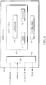
controller 15 is shown inFIG. 6 . Thecontroller 15 containscontrol logic 67 that includes asafety check 63 before allowing themachine 13 to run. Thesafety check 63 may prevent themachine 13 from running while configured for the wrong material. The signals from the sensors 22-24 are used as feedback related to the material that is loaded into themachine 13 for thesafety check 63 to perform its comparison of the material 12 to the configuration of thecontrol logic 67. - An
example method 70 of operation of thesafety check 63 of thecontroller 15 is shown inFIG. 7 . At 72, thecontroller 15 receives through I/O 62 signals from the sensors 22-24 related to the type ofmaterial 12 at theinput 17 to themachine 13. From the sensors 22-24, thecontroller 15 receives information related to thematerial 12 being present at theinput 17 to themachine 13, information related to the degree of absorbency, or reflectivity of thematerial 12, and information related to the type of thematerial 12. Using this information, at 73, thecontroller 15 determines a sensed type ofmaterial 12. For example, the sensed type ofmaterial 12 can be standard thinplate steel (mild tin plated steel), black thinplate steel (mild tin plated steel painted black), ultra stainless steel, copper, brass, aluminum or black ultra stainless steel (stainless steel painted black) determined based on information from theMC sensor 23 and theMT sensor 24. Through the I/O 62, at 74, thecontroller 15 receives a configuration signal from theUI 16. This configuration signal is received before, at about the same time, or after the signals are received from the sensors 22-24. At 75, the configured type of material is determined by thecontroller 15. - At 76, the
comparator 64 of thesafety check 63 matches the sensed type of material to the configured type of material. If there is a match between the sensed type of material and the configured type of material, at 77, thecontrol logic 67 allows themachine 13 to proceed with the configuration for the material. Thecontroller 15 communicates at least a portion of thecontrol logic 67 configured as is to themachine 13 through the I/O 62 to control operations of themachine 13 and its components. However, if there is not a match between the sensed type of material and the configured type of material, at 78, thecontrol logic 67 allows thecontroller 15 to hold the process in order for the configuration to be changed. Thecontroller 15 communicates with theUI 16 through the I/O 62 to undertake the reconfiguration for the sensed type of material. After the configuration is changed, thecontroller 15 communicates at least a portion of the reconfiguredcontrol logic 67 to themachine 13. -
Different example UIs 16 are shown inFIGS. 8-11 . The examples inFIGS. 8-11 correspond to operation of a feeder press. Shown inFIG. 8 is a basicoperator interface screen 500 allowing selection of the type ofmaterial 12 being loaded into themachine 13. Aselector switch 502 is included to select the material. In this example, an operator moves theselector switch 502 to the left or right to the position corresponding to the material 12 to be entered into themachine 13. -
FIG. 9 shows an example of adifferent user interface 600 seen by someone who logs in as an Administrator. An Administrator has different permissions than a general operator such that the Administrator reconfigures the UI. For example, thedifferent user interface 600 will display asetup button 604 in connection with theselector switch 502 such that when the setup button is pressed, anotheroperator interface screen 700 shown inFIG. 10 appears that allows the Administrator to select a number of materials (e.g., two) to appear on theoperator interface screen 500 ofFIG. 8 . The materials selected should ultimately match the configuration of themachine 13. For example, die stops that are installed on quick change platens indicate materials that can be used on themachine 13 without damaging the machine. Theoperator interface 700 ofFIG. 10 also includes acheck box 702 telling thecontroller 15 to ignore the inputs from the sensors 22-24. For example, the Administrator could check this box in the event that one or more of the materials sensors were to go bad and themachine 13 was still desirous to run the machine.FIG. 11 shows an example of anoperator interface 800 that is automatically updated with the two materials that are selected by the Administrator. If either of the two material selections fails to match the material 12 that is loaded into themachine 13, amessage 802 appears in the top right corner of the operator interface screen 800(seeFIG. 11 ) alerting the user of the operator interface and/or the person who loaded the material into the machine. When themessage 802 appears on theoperator interface screen 800, themachine 13 will also be prevented from running in AUTO mode unless the "ignore material sensors"checkbox 702 is checked or the material type selector is updated to reflect what is actually in themachine 13. - In yet another example, a material type will be predetermined via a schedule that is downloaded onto the
controller 15, rather than being manually selected as indicated inFIGS. 8-11 . In an example embodiment, the schedule is downloaded via a communication port (e.g., a USB port, a signal transceiver, a signal receiver, or the like). - In the foregoing specification, specific embodiments have been described. However, one of ordinary skill in the art appreciates that various modifications and changes can be made, limited only by the scope of the appended claims. Accordingly, the specification and figures are to be regarded in an illustrative rather than a restrictive sense, and all such modifications are limited only by the scope of the appended claims.
- The benefits, advantages, solutions to problems, and any element(s) that may cause any benefit, advantage, or solution to occur or become more pronounced are not to be construed as a critical, required, or essential features or elements of any or all the claims. The disclosure is defined solely by the appended claims including any amendments made during the pendency of this application.
- Moreover in this document, relational terms such as first and second, top and bottom, and the like may be used solely to distinguish one entity or action from another entity or action without necessarily requiring or implying any actual such relationship or order between such entities or actions. The terms "comprises," "comprising," "has", "having," "includes", "including," "contains", "containing" or any other variation thereof, are intended to cover a non-exclusive inclusion, such that a process, method, article, or apparatus that comprises, has, includes, contains a list of elements does not include only those elements but may include other elements not expressly listed or inherent to such process, method, article, or apparatus. An element proceeded by "comprises ...a", "has ...a", "includes ...a", "contains ...a" does not, without more constraints, preclude the existence of additional identical elements in the process, method, article, or apparatus that comprises, has, includes, contains the element. The terms "a" and "an" are defined as one or more unless explicitly stated otherwise herein. The terms "substantially", "essentially", "approximately", "about" or any other version thereof, are defined as being close to as understood by one of ordinary skill in the art, and in one non-limiting embodiment the term is defined to be within 10%, in another embodiment within 5%, in another embodiment within 1% and in another embodiment within 0.5%. The term "coupled" as used herein is defined as connected, although not necessarily directly and not necessarily mechanically. A device or structure that is "configured" in a certain way is configured in at least that way, but may also be configured in ways that are not listed.
- It will be appreciated that some embodiments may be comprised of one or more generic or specialized processors (or "processing devices") such as microprocessors, digital signal processors, customized processors and field programmable gate arrays (FPGAs) and unique stored program instructions (including both software and firmware) that control the one or more processors to implement, in conjunction with certain non-processor circuits, some, most, or all of the functions of the method and/or apparatus described herein. Alternatively, some or all functions could be implemented by a state machine that has no stored program instructions, or in one or more application specific integrated circuits (ASICs), in which each function or some combinations of certain of the functions are implemented as custom logic. Of course, a combination of the two approaches could be used.
- Moreover, an embodiment can be implemented as a computer-readable storage medium having computer readable code stored thereon for programming a computer (e.g., comprising a processor) to perform a method as described and claimed herein. Examples of such computer-readable storage mediums include, but are not limited to, a hard disk, a CD-ROM, an optical storage device, a magnetic storage device, a ROM (Read Only Memory), a PROM (Programmable Read Only Memory), an EPROM (Erasable Programmable Read Only Memory), an EEPROM (Electrically Erasable Programmable Read Only Memory) and a Flash memory. Further, it is expected that one of ordinary skill, notwithstanding possibly significant effort and many design choices motivated by, for example, available time, current technology, and economic considerations, when guided by the concepts and principles disclosed herein will be readily capable of generating such software instructions and programs and ICs with minimal experimentation.
- The Abstract of the Disclosure is provided to allow the reader to quickly ascertain the nature of the technical disclosure. It is submitted with the understanding that it will not be used to interpret or limit the scope or meaning of the claims. In addition, in the foregoing Detailed Description, it can be seen that various features are grouped together in various embodiments for the purpose of streamlining the disclosure. This method of disclosure is not to be interpreted as reflecting an intention that the claimed embodiments require more features than are expressly recited in each claim. Rather, as the following claims reflect, inventive subject matter lies in less than all features of a single disclosed embodiment. Thus the following claims are hereby incorporated into the Detailed Description, with each claim standing on its own as a separately claimed subject matter.
Claims (13)
- A system comprising:a detection system (10) to detect a presence of an input metal material (12) during use at an input to a machine (13) and to detect properties of the input metal material, the detection system comprising:a material present sensor (22);an inductive sensor (24) positioned on one side of an input path for detecting a property of the input metal material;an other metal material (25), different from said input metal material and positioned on an opposite side from said one side of the input path and opposed to the inductive sensor (24) at a suitable separation to impact an inductive sensor signal based on a property of the input metal material; wherein an inductive sensor correction factor of the said inductive sensor (24) for the said other metal material (25) is 0.5 or less; anda material color sensor (23); anda controller (15) of the machine (13) for monitoring a signal from the material present sensor (22), for monitoring the signal from the inductive sensor (24), and for monitoring a signal from the material color sensor (23) to adjust at least one parameter of the machine (13) based on a type of the input metal material determined from the properties of the input metal material wherein the input metal material during use is placed between the inductive sensor (24) and the other metal material (25).
- The system of claim 1, wherein the material present sensor comprises an inductive proximity sensor (22) configured to detect the presence of a metal material at the input path to the machine (13).
- The system of claim 1, wherein the input metal material during use comprises a stainless steel or a mild steel.
- The system of claim 1, wherein the inductive sensor (24) is configured to detect a portion of a magnetic field not absorbed by the input metal material.
- The system of claim 1, wherein the inductive sensor (24) couples a signal to the controller (15) and the controller discriminates between a mild steel of the input metal material and a stainless steel of the input metal material based on the signal.
- The system of claim 1, wherein the other metal material (25) is in a shape of a block or a cylinder and comprises at least one of brass, aluminum, and copper.
- The system of claim 1, wherein the material color sensor comprises a diffuse reflective photoelectric sensor (23) configured to determine at least one of a degree of absorbency and a degree of reflectivity of the input metal material.
- The system of claim 1, wherein the controller (15) is programmed to determine the type and grade of the input metal material based on signals received from the material present sensor, the inductive sensor (22), and the material color sensor (23).
- The system of claim 1, wherein the controller (15) is programmed to compare safe parameters related to the type of the input metal material to material parameters selected from an input to a graphical user interface (500, 600, 700, 800) to allow for an automated change over to prevent damage to the machine (500, 600, 700, 800).
- The system of claim 1 further comprising:at least one of a user interface (500, 600, 700, 800) and communication port that receives a selection of the type of the input metal material to be loaded into the machine; andsaid controller (15) performs a safety check matching the selected material type to a material type determined based on signals received from a plurality of sensors comprising the material present sensor (22), the inductive sensor opposed by the other material, and the material color sensor (23).
- A method of detecting a type of an input metal material (12) to be processed by a machine (13), the method comprising the steps of:providing a material present sensor (22);providing an inductive sensor (24) and positioning the inductive sensor on one side of a material input path for detecting a property of the input metal material;providing a different metal material (25) on an opposite side from said one side of the input path and opposed to the inductive sensor (24) at a suitable separation to impact an inductive sensor signal based on a property of the input metal material;wherein an induction sensor correction factor of the said inductive sensor (24) for the said other metal (25) is 0.5 or less; providing a material color sensor (23);providing a controller (15) in the machine (13) having a feedback loop to adjust at least one parameter of the machine based on the type of the input metal material detected from one or more of the material present sensor (22), the inductive sensor (24) and the material color sensor (23); andproviding an input metal material to be identified between the inductive sensor and the different metal material (25).
- The method of claim 11, further comprising at least one of the following steps:providing an inductive proximity sensor configured to detect the presence of a metal material at the input to the machine;providing a diffuse reflective photoelectric sensor that determines a contrast of the material;determining the type and grade of the material based upon signals received from the inductive sensor and the material color sensor;providing at least one of brass, aluminum, and copper to comprise the different material;detecting a portion of a magnetic field not absorbed by the different material to determine the material type; andcomparing safe parameters related to the type of material detected by the sensors to a material selected based on the selection of a material type to allow for a change over to prevent damage to the machine.
- A system of claim 1 wherein:
the controller of the machine includes a feedback loop to the machine, which performs a safety check matching a selected material type to a material type determined based on signals received from the sensors and based upon a prior and different material processed by said machine during use, said controller adjusts at least one parameter of the machine based on a type of a subsequent material determined based on the properties of the subsequent material to prevent damage to the machine.
Priority Applications (1)
| Application Number | Priority Date | Filing Date | Title |
|---|---|---|---|
| PL17739041T PL3402627T3 (en) | 2016-01-14 | 2017-01-13 | Material detection system |
Applications Claiming Priority (2)
| Application Number | Priority Date | Filing Date | Title |
|---|---|---|---|
| US201662278701P | 2016-01-14 | 2016-01-14 | |
| PCT/US2017/013421 WO2017123936A1 (en) | 2016-01-14 | 2017-01-13 | Material detection system |
Publications (3)
| Publication Number | Publication Date |
|---|---|
| EP3402627A1 EP3402627A1 (en) | 2018-11-21 |
| EP3402627A4 EP3402627A4 (en) | 2019-08-21 |
| EP3402627B1 true EP3402627B1 (en) | 2020-10-21 |
Family
ID=59311550
Family Applications (1)
| Application Number | Title | Priority Date | Filing Date |
|---|---|---|---|
| EP17739041.6A Not-in-force EP3402627B1 (en) | 2016-01-14 | 2017-01-13 | Material detection system |
Country Status (7)
| Country | Link |
|---|---|
| US (1) | US10156515B2 (en) |
| EP (1) | EP3402627B1 (en) |
| CA (1) | CA3032357C (en) |
| ES (1) | ES2844979T3 (en) |
| MX (1) | MX2018008728A (en) |
| PL (1) | PL3402627T3 (en) |
| WO (1) | WO2017123936A1 (en) |
Families Citing this family (2)
| Publication number | Priority date | Publication date | Assignee | Title |
|---|---|---|---|---|
| EP3858541B1 (en) | 2018-09-26 | 2024-08-21 | Dalian University Of Technology | Automatic hole-making method with self-adapting adjustment of processing parameter |
| EP4217119A1 (en) | 2020-09-28 | 2023-08-02 | Vitro Flat Glass LLC | Device for distributing sealant materials and methods of using the same |
Family Cites Families (13)
| Publication number | Priority date | Publication date | Assignee | Title |
|---|---|---|---|---|
| US3889503A (en) * | 1974-07-01 | 1975-06-17 | Verson Allsteel Press Co | Safety indicator system and method for metal forming machines |
| US4400850A (en) * | 1982-03-01 | 1983-08-30 | Herman E. Cox | Foreign object detector for protection of carding machines |
| US5284012A (en) | 1991-05-16 | 1994-02-08 | General Electric Company | Nacelle cooling and ventilation system |
| US6060677A (en) * | 1994-08-19 | 2000-05-09 | Tiedemanns-Jon H. Andresen Ans | Determination of characteristics of material |
| US7610681B2 (en) | 2004-09-29 | 2009-11-03 | Ged Integrated Solutions, Inc. | Window component stock indexing |
| US7674994B1 (en) * | 2004-10-21 | 2010-03-09 | Valerio Thomas A | Method and apparatus for sorting metal |
| CA2647700C (en) * | 2006-03-31 | 2012-12-11 | Thomas Valerio | Method and apparatus for sorting fine nonferrous metals and insulated wire pieces |
| US7448246B2 (en) | 2006-05-02 | 2008-11-11 | Ged Integrated Solutions, Inc. | Window frame corner fabrication |
| US8154278B2 (en) * | 2008-01-26 | 2012-04-10 | Pepperl+Fuchs, Inc. | Metal face inductive proximity sensor |
| DE102008049908A1 (en) * | 2008-10-02 | 2010-04-08 | Robert Bosch Gmbh | Method for generating a detection signal and detection device |
| RU2561475C2 (en) * | 2010-03-24 | 2015-08-27 | Рэ-Пэт Лтд | Grinder |
| US9765564B2 (en) | 2013-03-14 | 2017-09-19 | Ged Integrated Solutions, Inc. | Automated spacer frame fabrication and method |
| US9082447B1 (en) * | 2014-09-22 | 2015-07-14 | WD Media, LLC | Determining storage media substrate material type |
-
2017
- 2017-01-13 US US15/405,954 patent/US10156515B2/en active Active
- 2017-01-13 MX MX2018008728A patent/MX2018008728A/en unknown
- 2017-01-13 CA CA3032357A patent/CA3032357C/en active Active
- 2017-01-13 PL PL17739041T patent/PL3402627T3/en unknown
- 2017-01-13 WO PCT/US2017/013421 patent/WO2017123936A1/en not_active Ceased
- 2017-01-13 EP EP17739041.6A patent/EP3402627B1/en not_active Not-in-force
- 2017-01-13 ES ES17739041T patent/ES2844979T3/en active Active
Non-Patent Citations (1)
| Title |
|---|
| None * |
Also Published As
| Publication number | Publication date |
|---|---|
| US20170205334A1 (en) | 2017-07-20 |
| CA3032357A1 (en) | 2017-07-20 |
| CA3032357C (en) | 2024-02-27 |
| MX2018008728A (en) | 2018-09-28 |
| EP3402627A4 (en) | 2019-08-21 |
| US10156515B2 (en) | 2018-12-18 |
| EP3402627A1 (en) | 2018-11-21 |
| PL3402627T3 (en) | 2021-04-19 |
| ES2844979T3 (en) | 2021-07-23 |
| WO2017123936A1 (en) | 2017-07-20 |
Similar Documents
| Publication | Publication Date | Title |
|---|---|---|
| EP3402627B1 (en) | Material detection system | |
| EP2969616B1 (en) | Window assembly with a transparent electrically conductive layer | |
| CN109692876B (en) | A method for controlling the edge punching of strip steel by crescent scissors | |
| CN216505346U (en) | cutting device | |
| US9965927B2 (en) | Checkout system assembly with goods separator detection | |
| CN103219586A (en) | Automatic detection, correction and adjustment method and system for panel antenna | |
| CN111222605B (en) | RFID tag recognition device | |
| KR102265698B1 (en) | quality data analysis using press forming information and recipe optimization method | |
| CN111153268A (en) | Feeding system and control method thereof | |
| EP3218159B1 (en) | Method of manufacturing a material strand | |
| CA3102974C (en) | Inspection tracking system | |
| EP4270572B1 (en) | Electrode sheet cutting device and cutting method | |
| CN107813074A (en) | A kind of automatic welding machine | |
| CN208561097U (en) | A kind of carrier band rolling-up mechanism | |
| CN105500438A (en) | Cutting device used for cutting lining tire side wall composite part and cutting method thereof | |
| CN210759174U (en) | Hot-pressing beveling device | |
| CN210668101U (en) | Sleeve conveying detection mechanism and transformer coil pipe-penetrating winding machine | |
| WO2017184236A1 (en) | Automated vehicle operation based on observed movement of other vehicles | |
| KR101137071B1 (en) | Device for manufacturing flexible falt cable controlling slitting error automatically and slitting error controlling method of saidd | |
| CN113601315B (en) | Control method, control device, edging system and storage medium of edging system | |
| CN115338670B (en) | Numerical control processing method, device, equipment and system | |
| JP2020110982A (en) | Manufacturing method of strip member for tire | |
| WO2023003706A1 (en) | Systems and methods for adaptive beam steering for throughways | |
| EP3907029A1 (en) | A system, method and computer program product for decreasing the risk of erroneously handling of a tool in a machine operation | |
| CN222165941U (en) | Detection device |
Legal Events
| Date | Code | Title | Description |
|---|---|---|---|
| STAA | Information on the status of an ep patent application or granted ep patent |
Free format text: STATUS: THE INTERNATIONAL PUBLICATION HAS BEEN MADE |
|
| PUAI | Public reference made under article 153(3) epc to a published international application that has entered the european phase |
Free format text: ORIGINAL CODE: 0009012 |
|
| STAA | Information on the status of an ep patent application or granted ep patent |
Free format text: STATUS: REQUEST FOR EXAMINATION WAS MADE |
|
| 17P | Request for examination filed |
Effective date: 20180807 |
|
| AK | Designated contracting states |
Kind code of ref document: A1 Designated state(s): AL AT BE BG CH CY CZ DE DK EE ES FI FR GB GR HR HU IE IS IT LI LT LU LV MC MK MT NL NO PL PT RO RS SE SI SK SM TR |
|
| AX | Request for extension of the european patent |
Extension state: BA ME |
|
| DAV | Request for validation of the european patent (deleted) | ||
| DAX | Request for extension of the european patent (deleted) | ||
| A4 | Supplementary search report drawn up and despatched |
Effective date: 20190723 |
|
| RIC1 | Information provided on ipc code assigned before grant |
Ipc: G01N 33/20 20190101ALI20190717BHEP Ipc: G01N 27/00 20060101ALI20190717BHEP Ipc: G01N 21/86 20060101ALI20190717BHEP Ipc: B21D 43/00 20060101ALI20190717BHEP Ipc: E06B 3/673 20060101ALN20190717BHEP Ipc: G01N 21/47 20060101ALI20190717BHEP Ipc: G01N 21/25 20060101ALI20190717BHEP Ipc: B23Q 17/20 20060101AFI20190717BHEP |
|
| GRAP | Despatch of communication of intention to grant a patent |
Free format text: ORIGINAL CODE: EPIDOSNIGR1 |
|
| STAA | Information on the status of an ep patent application or granted ep patent |
Free format text: STATUS: GRANT OF PATENT IS INTENDED |
|
| RIC1 | Information provided on ipc code assigned before grant |
Ipc: E06B 3/673 20060101ALN20200417BHEP Ipc: B21D 43/00 20060101ALI20200417BHEP Ipc: G01N 21/25 20060101ALI20200417BHEP Ipc: G01N 27/72 20060101ALN20200417BHEP Ipc: G01N 33/20 20190101ALI20200417BHEP Ipc: G01N 21/47 20060101ALI20200417BHEP Ipc: G01N 21/86 20060101ALI20200417BHEP Ipc: B23Q 17/20 20060101AFI20200417BHEP |
|
| RIC1 | Information provided on ipc code assigned before grant |
Ipc: B21D 43/00 20060101ALI20200428BHEP Ipc: G01N 21/86 20060101ALI20200428BHEP Ipc: E06B 3/673 20060101ALN20200428BHEP Ipc: G01N 33/20 20190101ALI20200428BHEP Ipc: G01N 21/25 20060101ALI20200428BHEP Ipc: G01N 27/72 20060101ALN20200428BHEP Ipc: G01N 21/47 20060101ALI20200428BHEP Ipc: B23Q 17/20 20060101AFI20200428BHEP |
|
| INTG | Intention to grant announced |
Effective date: 20200518 |
|
| GRAS | Grant fee paid |
Free format text: ORIGINAL CODE: EPIDOSNIGR3 |
|
| GRAA | (expected) grant |
Free format text: ORIGINAL CODE: 0009210 |
|
| STAA | Information on the status of an ep patent application or granted ep patent |
Free format text: STATUS: THE PATENT HAS BEEN GRANTED |
|
| AK | Designated contracting states |
Kind code of ref document: B1 Designated state(s): AL AT BE BG CH CY CZ DE DK EE ES FI FR GB GR HR HU IE IS IT LI LT LU LV MC MK MT NL NO PL PT RO RS SE SI SK SM TR |
|
| REG | Reference to a national code |
Ref country code: GB Ref legal event code: FG4D |
|
| REG | Reference to a national code |
Ref country code: CH Ref legal event code: EP |
|
| REG | Reference to a national code |
Ref country code: DE Ref legal event code: R096 Ref document number: 602017025881 Country of ref document: DE |
|
| REG | Reference to a national code |
Ref country code: IE Ref legal event code: FG4D |
|
| REG | Reference to a national code |
Ref country code: AT Ref legal event code: REF Ref document number: 1325355 Country of ref document: AT Kind code of ref document: T Effective date: 20201115 |
|
| PGFP | Annual fee paid to national office [announced via postgrant information from national office to epo] |
Ref country code: FR Payment date: 20201102 Year of fee payment: 5 Ref country code: GB Payment date: 20201102 Year of fee payment: 5 |
|
| REG | Reference to a national code |
Ref country code: AT Ref legal event code: MK05 Ref document number: 1325355 Country of ref document: AT Kind code of ref document: T Effective date: 20201021 |
|
| REG | Reference to a national code |
Ref country code: NL Ref legal event code: MP Effective date: 20201021 |
|
| PG25 | Lapsed in a contracting state [announced via postgrant information from national office to epo] |
Ref country code: RS Free format text: LAPSE BECAUSE OF FAILURE TO SUBMIT A TRANSLATION OF THE DESCRIPTION OR TO PAY THE FEE WITHIN THE PRESCRIBED TIME-LIMIT Effective date: 20201021 Ref country code: PT Free format text: LAPSE BECAUSE OF FAILURE TO SUBMIT A TRANSLATION OF THE DESCRIPTION OR TO PAY THE FEE WITHIN THE PRESCRIBED TIME-LIMIT Effective date: 20210222 Ref country code: NO Free format text: LAPSE BECAUSE OF FAILURE TO SUBMIT A TRANSLATION OF THE DESCRIPTION OR TO PAY THE FEE WITHIN THE PRESCRIBED TIME-LIMIT Effective date: 20210121 Ref country code: GR Free format text: LAPSE BECAUSE OF FAILURE TO SUBMIT A TRANSLATION OF THE DESCRIPTION OR TO PAY THE FEE WITHIN THE PRESCRIBED TIME-LIMIT Effective date: 20210122 Ref country code: FI Free format text: LAPSE BECAUSE OF FAILURE TO SUBMIT A TRANSLATION OF THE DESCRIPTION OR TO PAY THE FEE WITHIN THE PRESCRIBED TIME-LIMIT Effective date: 20201021 |
|
| PGFP | Annual fee paid to national office [announced via postgrant information from national office to epo] |
Ref country code: IE Payment date: 20210105 Year of fee payment: 5 Ref country code: IT Payment date: 20201211 Year of fee payment: 5 |
|
| REG | Reference to a national code |
Ref country code: LT Ref legal event code: MG4D |
|
| PG25 | Lapsed in a contracting state [announced via postgrant information from national office to epo] |
Ref country code: AT Free format text: LAPSE BECAUSE OF FAILURE TO SUBMIT A TRANSLATION OF THE DESCRIPTION OR TO PAY THE FEE WITHIN THE PRESCRIBED TIME-LIMIT Effective date: 20201021 Ref country code: BG Free format text: LAPSE BECAUSE OF FAILURE TO SUBMIT A TRANSLATION OF THE DESCRIPTION OR TO PAY THE FEE WITHIN THE PRESCRIBED TIME-LIMIT Effective date: 20210121 Ref country code: LV Free format text: LAPSE BECAUSE OF FAILURE TO SUBMIT A TRANSLATION OF THE DESCRIPTION OR TO PAY THE FEE WITHIN THE PRESCRIBED TIME-LIMIT Effective date: 20201021 Ref country code: IS Free format text: LAPSE BECAUSE OF FAILURE TO SUBMIT A TRANSLATION OF THE DESCRIPTION OR TO PAY THE FEE WITHIN THE PRESCRIBED TIME-LIMIT Effective date: 20210221 Ref country code: SE Free format text: LAPSE BECAUSE OF FAILURE TO SUBMIT A TRANSLATION OF THE DESCRIPTION OR TO PAY THE FEE WITHIN THE PRESCRIBED TIME-LIMIT Effective date: 20201021 |
|
| PGFP | Annual fee paid to national office [announced via postgrant information from national office to epo] |
Ref country code: DE Payment date: 20210126 Year of fee payment: 5 Ref country code: PL Payment date: 20201204 Year of fee payment: 5 |
|
| PG25 | Lapsed in a contracting state [announced via postgrant information from national office to epo] |
Ref country code: NL Free format text: LAPSE BECAUSE OF FAILURE TO SUBMIT A TRANSLATION OF THE DESCRIPTION OR TO PAY THE FEE WITHIN THE PRESCRIBED TIME-LIMIT Effective date: 20201021 Ref country code: HR Free format text: LAPSE BECAUSE OF FAILURE TO SUBMIT A TRANSLATION OF THE DESCRIPTION OR TO PAY THE FEE WITHIN THE PRESCRIBED TIME-LIMIT Effective date: 20201021 |
|
| REG | Reference to a national code |
Ref country code: DE Ref legal event code: R097 Ref document number: 602017025881 Country of ref document: DE |
|
| REG | Reference to a national code |
Ref country code: ES Ref legal event code: FG2A Ref document number: 2844979 Country of ref document: ES Kind code of ref document: T3 Effective date: 20210723 |
|
| PG25 | Lapsed in a contracting state [announced via postgrant information from national office to epo] |
Ref country code: RO Free format text: LAPSE BECAUSE OF FAILURE TO SUBMIT A TRANSLATION OF THE DESCRIPTION OR TO PAY THE FEE WITHIN THE PRESCRIBED TIME-LIMIT Effective date: 20201021 Ref country code: SK Free format text: LAPSE BECAUSE OF FAILURE TO SUBMIT A TRANSLATION OF THE DESCRIPTION OR TO PAY THE FEE WITHIN THE PRESCRIBED TIME-LIMIT Effective date: 20201021 Ref country code: SM Free format text: LAPSE BECAUSE OF FAILURE TO SUBMIT A TRANSLATION OF THE DESCRIPTION OR TO PAY THE FEE WITHIN THE PRESCRIBED TIME-LIMIT Effective date: 20201021 Ref country code: EE Free format text: LAPSE BECAUSE OF FAILURE TO SUBMIT A TRANSLATION OF THE DESCRIPTION OR TO PAY THE FEE WITHIN THE PRESCRIBED TIME-LIMIT Effective date: 20201021 Ref country code: CZ Free format text: LAPSE BECAUSE OF FAILURE TO SUBMIT A TRANSLATION OF THE DESCRIPTION OR TO PAY THE FEE WITHIN THE PRESCRIBED TIME-LIMIT Effective date: 20201021 Ref country code: LT Free format text: LAPSE BECAUSE OF FAILURE TO SUBMIT A TRANSLATION OF THE DESCRIPTION OR TO PAY THE FEE WITHIN THE PRESCRIBED TIME-LIMIT Effective date: 20201021 |
|
| PLBE | No opposition filed within time limit |
Free format text: ORIGINAL CODE: 0009261 |
|
| STAA | Information on the status of an ep patent application or granted ep patent |
Free format text: STATUS: NO OPPOSITION FILED WITHIN TIME LIMIT |
|
| PG25 | Lapsed in a contracting state [announced via postgrant information from national office to epo] |
Ref country code: DK Free format text: LAPSE BECAUSE OF FAILURE TO SUBMIT A TRANSLATION OF THE DESCRIPTION OR TO PAY THE FEE WITHIN THE PRESCRIBED TIME-LIMIT Effective date: 20201021 Ref country code: MC Free format text: LAPSE BECAUSE OF FAILURE TO SUBMIT A TRANSLATION OF THE DESCRIPTION OR TO PAY THE FEE WITHIN THE PRESCRIBED TIME-LIMIT Effective date: 20201021 |
|
| REG | Reference to a national code |
Ref country code: CH Ref legal event code: PL |
|
| 26N | No opposition filed |
Effective date: 20210722 |
|
| PG25 | Lapsed in a contracting state [announced via postgrant information from national office to epo] |
Ref country code: LU Free format text: LAPSE BECAUSE OF NON-PAYMENT OF DUE FEES Effective date: 20210113 |
|
| REG | Reference to a national code |
Ref country code: BE Ref legal event code: MM Effective date: 20210131 |
|
| PG25 | Lapsed in a contracting state [announced via postgrant information from national office to epo] |
Ref country code: AL Free format text: LAPSE BECAUSE OF FAILURE TO SUBMIT A TRANSLATION OF THE DESCRIPTION OR TO PAY THE FEE WITHIN THE PRESCRIBED TIME-LIMIT Effective date: 20201021 |
|
| PG25 | Lapsed in a contracting state [announced via postgrant information from national office to epo] |
Ref country code: LI Free format text: LAPSE BECAUSE OF NON-PAYMENT OF DUE FEES Effective date: 20210131 Ref country code: CH Free format text: LAPSE BECAUSE OF NON-PAYMENT OF DUE FEES Effective date: 20210131 Ref country code: SI Free format text: LAPSE BECAUSE OF FAILURE TO SUBMIT A TRANSLATION OF THE DESCRIPTION OR TO PAY THE FEE WITHIN THE PRESCRIBED TIME-LIMIT Effective date: 20201021 |
|
| PGFP | Annual fee paid to national office [announced via postgrant information from national office to epo] |
Ref country code: ES Payment date: 20210726 Year of fee payment: 5 |
|
| PG25 | Lapsed in a contracting state [announced via postgrant information from national office to epo] |
Ref country code: IS Free format text: LAPSE BECAUSE OF FAILURE TO SUBMIT A TRANSLATION OF THE DESCRIPTION OR TO PAY THE FEE WITHIN THE PRESCRIBED TIME-LIMIT Effective date: 20210221 |
|
| PG25 | Lapsed in a contracting state [announced via postgrant information from national office to epo] |
Ref country code: BE Free format text: LAPSE BECAUSE OF NON-PAYMENT OF DUE FEES Effective date: 20210131 |
|
| REG | Reference to a national code |
Ref country code: DE Ref legal event code: R119 Ref document number: 602017025881 Country of ref document: DE |
|
| GBPC | Gb: european patent ceased through non-payment of renewal fee |
Effective date: 20220113 |
|
| PG25 | Lapsed in a contracting state [announced via postgrant information from national office to epo] |
Ref country code: GB Free format text: LAPSE BECAUSE OF NON-PAYMENT OF DUE FEES Effective date: 20220113 Ref country code: DE Free format text: LAPSE BECAUSE OF NON-PAYMENT OF DUE FEES Effective date: 20220802 |
|
| PG25 | Lapsed in a contracting state [announced via postgrant information from national office to epo] |
Ref country code: FR Free format text: LAPSE BECAUSE OF NON-PAYMENT OF DUE FEES Effective date: 20220131 |
|
| PG25 | Lapsed in a contracting state [announced via postgrant information from national office to epo] |
Ref country code: IT Free format text: LAPSE BECAUSE OF NON-PAYMENT OF DUE FEES Effective date: 20220113 Ref country code: IE Free format text: LAPSE BECAUSE OF NON-PAYMENT OF DUE FEES Effective date: 20220113 |
|
| REG | Reference to a national code |
Ref country code: ES Ref legal event code: FD2A Effective date: 20230224 |
|
| PG25 | Lapsed in a contracting state [announced via postgrant information from national office to epo] |
Ref country code: ES Free format text: LAPSE BECAUSE OF NON-PAYMENT OF DUE FEES Effective date: 20220114 |
|
| PG25 | Lapsed in a contracting state [announced via postgrant information from national office to epo] |
Ref country code: CY Free format text: LAPSE BECAUSE OF FAILURE TO SUBMIT A TRANSLATION OF THE DESCRIPTION OR TO PAY THE FEE WITHIN THE PRESCRIBED TIME-LIMIT Effective date: 20201021 |
|
| P01 | Opt-out of the competence of the unified patent court (upc) registered |
Effective date: 20230615 |
|
| PG25 | Lapsed in a contracting state [announced via postgrant information from national office to epo] |
Ref country code: HU Free format text: LAPSE BECAUSE OF FAILURE TO SUBMIT A TRANSLATION OF THE DESCRIPTION OR TO PAY THE FEE WITHIN THE PRESCRIBED TIME-LIMIT; INVALID AB INITIO Effective date: 20170113 |
|
| PG25 | Lapsed in a contracting state [announced via postgrant information from national office to epo] |
Ref country code: MK Free format text: LAPSE BECAUSE OF FAILURE TO SUBMIT A TRANSLATION OF THE DESCRIPTION OR TO PAY THE FEE WITHIN THE PRESCRIBED TIME-LIMIT Effective date: 20201021 |
|
| PG25 | Lapsed in a contracting state [announced via postgrant information from national office to epo] |
Ref country code: PL Free format text: LAPSE BECAUSE OF NON-PAYMENT OF DUE FEES Effective date: 20220113 |
|
| PG25 | Lapsed in a contracting state [announced via postgrant information from national office to epo] |
Ref country code: TR Free format text: LAPSE BECAUSE OF FAILURE TO SUBMIT A TRANSLATION OF THE DESCRIPTION OR TO PAY THE FEE WITHIN THE PRESCRIBED TIME-LIMIT Effective date: 20201021 |
|
| PG25 | Lapsed in a contracting state [announced via postgrant information from national office to epo] |
Ref country code: MT Free format text: LAPSE BECAUSE OF FAILURE TO SUBMIT A TRANSLATION OF THE DESCRIPTION OR TO PAY THE FEE WITHIN THE PRESCRIBED TIME-LIMIT Effective date: 20201021 |