EP3402615B1 - Sammeltrommel für walzwerk - Google Patents
Sammeltrommel für walzwerk Download PDFInfo
- Publication number
- EP3402615B1 EP3402615B1 EP16822335.2A EP16822335A EP3402615B1 EP 3402615 B1 EP3402615 B1 EP 3402615B1 EP 16822335 A EP16822335 A EP 16822335A EP 3402615 B1 EP3402615 B1 EP 3402615B1
- Authority
- EP
- European Patent Office
- Prior art keywords
- coil
- pouring reel
- coil plate
- tub
- cylindrical tub
- Prior art date
- Legal status (The legal status is an assumption and is not a legal conclusion. Google has not performed a legal analysis and makes no representation as to the accuracy of the status listed.)
- Active
Links
Images


Classifications
-
- B—PERFORMING OPERATIONS; TRANSPORTING
- B21—MECHANICAL METAL-WORKING WITHOUT ESSENTIALLY REMOVING MATERIAL; PUNCHING METAL
- B21C—MANUFACTURE OF METAL SHEETS, WIRE, RODS, TUBES, PROFILES OR LIKE SEMI-MANUFACTURED PRODUCTS OTHERWISE THAN BY ROLLING; AUXILIARY OPERATIONS USED IN CONNECTION WITH METAL-WORKING WITHOUT ESSENTIALLY REMOVING MATERIAL
- B21C47/00—Winding-up, coiling or winding-off metal wire, metal band or other flexible metal material characterised by features relevant to metal processing only
- B21C47/02—Winding-up or coiling
- B21C47/04—Winding-up or coiling on or in reels or drums, without using a moving guide
- B21C47/045—Winding-up or coiling on or in reels or drums, without using a moving guide in rotating drums
-
- B—PERFORMING OPERATIONS; TRANSPORTING
- B21—MECHANICAL METAL-WORKING WITHOUT ESSENTIALLY REMOVING MATERIAL; PUNCHING METAL
- B21C—MANUFACTURE OF METAL SHEETS, WIRE, RODS, TUBES, PROFILES OR LIKE SEMI-MANUFACTURED PRODUCTS OTHERWISE THAN BY ROLLING; AUXILIARY OPERATIONS USED IN CONNECTION WITH METAL-WORKING WITHOUT ESSENTIALLY REMOVING MATERIAL
- B21C47/00—Winding-up, coiling or winding-off metal wire, metal band or other flexible metal material characterised by features relevant to metal processing only
- B21C47/02—Winding-up or coiling
- B21C47/04—Winding-up or coiling on or in reels or drums, without using a moving guide
-
- B—PERFORMING OPERATIONS; TRANSPORTING
- B21—MECHANICAL METAL-WORKING WITHOUT ESSENTIALLY REMOVING MATERIAL; PUNCHING METAL
- B21C—MANUFACTURE OF METAL SHEETS, WIRE, RODS, TUBES, PROFILES OR LIKE SEMI-MANUFACTURED PRODUCTS OTHERWISE THAN BY ROLLING; AUXILIARY OPERATIONS USED IN CONNECTION WITH METAL-WORKING WITHOUT ESSENTIALLY REMOVING MATERIAL
- B21C47/00—Winding-up, coiling or winding-off metal wire, metal band or other flexible metal material characterised by features relevant to metal processing only
- B21C47/28—Drums or other coil-holders
Definitions
- This invention relates generally to hot rolling mills producing bars and other like long products, and is concerned in particular with pouring reels according to the preamble of claim 1 employed to receive and form such products into cylindrical coils.
- a bar product is effectively poured or fed via a nozzle into a rotating tub having radially spaced inner and outer walls defining an annular chamber closed at its lower end by a fixed tub bottom.
- the tub runs at a synchronous velocity to that of the entering bar.
- the nozzle is positioned such that when the bar enters the annular chamber, it contacts the outer tub wall at a tangent angle and then runs on the inner tub wall to form a spiral which accumulates as a cylindrical coil that starts at the tub bottom and forms itself vertically upward to fill the tub.
- Such conventional pouring reels operate satisfactorily at bar delivery speeds up to and including about 16m/sec. At higher speeds, however, the bar entering the tub is subjected to excessively high centripetal forces, which prevent the bar from feeding to the bottom of the tub as intended.
- the coil thus forms erratically and non-uniformly, with a lower than desired density. In extreme cases, the height of the low density coil is such that it spills out from the tub, creating both production problems and safety issues.
- the delivery nozzle is of necessity inclined at a relatively steep delivery angle, typically on the order of 50°.
- the tail end of the bar sticks up from the top of the coil at the same angle and must be pushed flat before the coil can be subjected to further processing.
- the objective of the present invention is to provide an improved pouring reel which avoids or at least substantially mitigates the above described problems.
- a pouring reel for forming a hot rolled long product into an annular coil comprises a central mast lying on a vertical axis.
- a cylindrical tub surrounds and cooperates with the central mast to form an annular tub chamber.
- a coil plate defines a bottom of the tub chamber.
- the central mast, cylindrical tub and coil plate are rotatable in unison about the vertical axis.
- An entry nozzle has a delivery end arranged to direct the product downwardly into the tub chamber for accumulation on the coil plate as a series of superimposed rings forming the coil.
- the coil plate is movable downwardly along the vertical axis and relative to the central mast and the cylindrical tub to accommodate the increasing height of the coil being formed in the tub chamber.
- Vertically traversable conveying elements are circumferentially spaced around and extend vertically along the interior surface of the cylindrical tub.
- the conveying elements are traversed downwardly and synchronously with the descending coil plate.
- this is achieved by coupling the conveying elements to the coil plate, although equivalent results may be achieved by separate drive mechanisms.
- conveyor elements is intended to include in particular conveyor chains.
- the conveying elements comprise inner runs of endless chains arranged to extend between upper and lower idlers carried by the cylindrical tub.
- the inner runs include face plates projecting radially inwardly from an interior surface of the cylindrical tub.
- the endless chains may have outer return runs extending vertically along the exterior surface of the cylindrical tub.
- the conveying elements may be received in and be traversable along guide channels in the interior surface of the cylindrical tub.
- the conveying elements may project radially inwardly from the interior surface of the cylindrical tub.
- Downward movement of the coil plate may also serve to maintain a substantially constant distance between the delivery end of the nozzle and the top of the coil being formed in the tub chamber.
- the entry nozzle may be arranged at an angle of between 25° and 35°, and preferably at an angle of 30°, with respect to the horizontal.
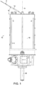
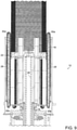
- FIG. 1 An exemplary embodiment of a pouring reel in accordance with the present invention is generally depicted at 10 in Fig. 1 .
- a nozzle 12 or other like delivery device serves to direct a hot rolled product "P" into the pouring reel where it is accumulated in the form of an annular coil.
- the pouring reel comprises a central mast 14 lying on a vertical axis "A" and defined by circumferentially spaced posts 14' projecting vertically from a base 16.
- a cylindrical tub 18 projects upwardly from the outer edge of base 16.
- the tub surrounds and cooperates with the mast 14 to form an annular chamber 20.
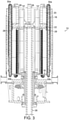
- a coil plate 22 defines a bottom of the annular chamber. As can be best seen in Fig. 2 , the coil plate 22 has notches 24 through which the posts 14' project, thereby rotationally coupling the coil plate to the central mast.
- the central mast 14, cylindrical tub 18 and coil plate 22, together with the base 16, are rotatable in unison about the vertical axis A.
- rotation will be at a synchronous velocity to that of the product entering the pouring reel, with the nozzle 12 being inclined as shown in Fig. 1 at an angle ⁇ with respect to the horizontal, and with its delivery end positioned to direct the product downwardly into the annular chamber 20 for accumulation on the coil plate as a series of superimposed rings.
- the coil plate 22 is vertically adjustable along axis A and relative to the central mast 14 and cylindrical tub 18. Such vertical adjustment may be achieved by an axially reciprocal central shaft 26. During a coil forming cycle, the coil plate 22 is gradually lowered to accommodate the increasing height of a coil being formed in chamber 20, while also maintaining a substantially constant distance between the delivery end of the nozzle 12 and the top of the growing coil.
- the conveying elements may comprise the inner runs of chain conveyors.
- the chain conveyor may be of the endless type running vertically between upper and lower sprockets 30a, 30b.
- the inner runs of the chain conveyors which serve as the conveying elements 28 may be received in and traversable along guide channels 32 in the interior surface of the tub 18, and may be coupled as at 34 to the coil plate 22.
- the outer return runs of the chain conveyors extend vertically along the exterior surface of the tub 18.
- the inner conveyor runs serving as the conveying elements may include face plates 36 that project radially inwardly as at 38 from the interior surface of the tub 16, and are thus positioned to be contacted by the entering product being urged radially outwardly by centripetal forces.
- the coil plate will descend at the correct rate selected to prevent the coil from spilling out of the top of the tub 18.
- the rate of descent will vary depending on product size and the delivery speed of the rolling mill.
- centripetal forces that might otherwise prevent the coil from forming uniformly from the fixed bottom of a conventional pouring reel tub are now employed advantageously. If and when the product is subjected to high centripetal forces when handling products at delivery speeds exceeding about 16m/sec, the vertically traversable conveying elements 28 connected to the coil plate 22 will move the product in contact therewith in the correct direction allowing the next ring to be formed in an orderly manner.
- Controlling the rate of coil plate descent controls coil formation. If a tight dense coil is required, the coil plate and conveying elements are moved downwardly at a slower rate. On the other hand, if a more open coil is required, the rate of descent can be increased, thus potentially leaving a small gap between each subsequent ring formed against the descending liner elements.
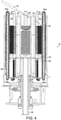
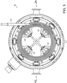
- Figs. 4 and 5 shown the pouring reel during a coil forming cycle, with the coil plate 22 descending towards the base 16.
- Fig. 8 shows the pouring reel at the completion of a coil forming cycle.
- Fig. 9 the coil plate has been adjusted to its uppermost level, which projects the completed coil vertically from the tub 18 in readiness for its removal from the pouring reel.
Landscapes
- Engineering & Computer Science (AREA)
- Mechanical Engineering (AREA)
- Winding, Rewinding, Material Storage Devices (AREA)
Claims (9)
- Gießhaspel (10) zum Formen eines warmgewalzten Langprodukts (P) zu einer ringförmigen Spule, umfassend:einen zentralen Mast (14), der auf einer vertikalen Achse (A) liegt;eine zylindrische Wanne (18), die den Mast umgibt und mit ihm zum Bilden einer Ringkammer (20) zusammenwirkt;eine Spulenplatte (22), die einen Boden der Kammer bildet;wobei der zentrale Mast, die zylindrische Wanne und die Spulenplatte gemeinsam um die vertikale Achse drehbar sind;eine Eintrittsdüse mit einem Abgabeende, das dazu angeordnet ist, das Produkt nach unten in die Kammer zu leiten, damit es sich auf der Spulenplatte als eine Reihe übereinanderliegender Ringe ansammelt, die die Spule bilden;wobei die Spulenplatte entlang der Achse und relativ zum zentralen Mast und der zylindrischen Wanne nach unten beweglich ist, um die zunehmende Höhe der in der Kammer geformten Spule aufzunehmen;vertikal verlaufende Förderelemente (28), die in Umfangsrichtung um eine Innenfläche der zylindrischen Wanne herum beabstandet sind, wobei die Förderelemente nach unten und synchron mit der Spulenplatte verfahrbar sind und innere Stränge von Endlosketten umfassen, und dadurch gekennzeichnet, dass die inneren Stränge Stirnplatten (36) beinhalten, die von einer Innenfläche der zylindrischen Wanne radial nach innen vorstehen.
- Gießhaspel nach Anspruch 1, wobei die vertikal verfahrbaren Förderelemente mit der Spulenplatte gekoppelt sind.
- Gießhaspel nach Anspruch 2, wobei sich die endlosen Förderketten zwischen oberen und unteren Tragrollen erstrecken, die von der zylindrischen Wanne getragen werden.
- Gießhaspel nach Anspruch 3, wobei die endlosen Förderketten äußere Rücklaufstrecken aufweisen, die sich vertikal entlang der Außenfläche der zylindrischen Wanne erstrecken.
- Gießhaspel nach Anspruch 3, wobei die inneren Stränge der Förderketten in Führungskanälen in der Innenfläche der zylindrischen Wanne aufgenommen werden und entlang dieser verfahrbar sind.
- Gießhaspel nach Anspruch 1, wobei die Spulenplatte nach unten beweglich ist, um einen im Wesentlichen konstanten Abstand zwischen dem Abgabeende der Düse und dem oberen Ende der in der Ringkammer gebildeten Spule aufrechtzuerhalten.
- Gießhaspel nach Anspruch 1, wobei die Eintrittsdüse in einem Winkel zwischen 25° und 35° gegenüber der Horizontalen angeordnet ist.
- Gießhaspel nach Anspruch 7, wobei der Winkel 30° beträgt.
- Gießhaspel nach Anspruch 1, wobei die Förderelemente mit der vertikalen Einstellung der Spulenplatte gekoppelt sind und von dieser angetrieben werden.
Priority Applications (1)
| Application Number | Priority Date | Filing Date | Title |
|---|---|---|---|
| PL16822335T PL3402615T3 (pl) | 2016-01-11 | 2016-12-14 | Bęben do nalewania walcarki |
Applications Claiming Priority (2)
| Application Number | Priority Date | Filing Date | Title |
|---|---|---|---|
| US201662277103P | 2016-01-11 | 2016-01-11 | |
| PCT/US2016/066620 WO2017123374A1 (en) | 2016-01-11 | 2016-12-14 | Rolling mill pouring reel |
Publications (2)
| Publication Number | Publication Date |
|---|---|
| EP3402615A1 EP3402615A1 (de) | 2018-11-21 |
| EP3402615B1 true EP3402615B1 (de) | 2022-02-09 |
Family
ID=57714691
Family Applications (1)
| Application Number | Title | Priority Date | Filing Date |
|---|---|---|---|
| EP16822335.2A Active EP3402615B1 (de) | 2016-01-11 | 2016-12-14 | Sammeltrommel für walzwerk |
Country Status (7)
| Country | Link |
|---|---|
| US (1) | US10888909B2 (de) |
| EP (1) | EP3402615B1 (de) |
| JP (1) | JP2019502561A (de) |
| KR (1) | KR102704805B1 (de) |
| ES (1) | ES2912326T3 (de) |
| PL (1) | PL3402615T3 (de) |
| WO (1) | WO2017123374A1 (de) |
Family Cites Families (13)
| Publication number | Priority date | Publication date | Assignee | Title |
|---|---|---|---|---|
| US434190A (en) * | 1890-08-12 | Rod-reel | ||
| US3618871A (en) * | 1969-08-01 | 1971-11-09 | Morgan Construction Co | Rod-intercepting means in a coil-forming chamber |
| DE2057899A1 (de) | 1970-11-25 | 1972-05-31 | Realid Ges Zur Realisierung Tc | Drehkorbhaspel zum Aufwickeln von Draht |
| JPS5347778B2 (de) | 1973-06-07 | 1978-12-23 | ||
| GB1459658A (en) | 1973-12-24 | 1976-12-22 | Moeller & Neumann Gmbh | Wire rod coiler for large bundles or coils |
| JPS5571862A (en) | 1978-11-21 | 1980-05-30 | Kanebo Ltd | Continuous liquid treating apparatus of cloth |
| JPS6227288Y2 (de) * | 1980-05-23 | 1987-07-13 | ||
| JPH0698389B2 (ja) | 1986-07-31 | 1994-12-07 | 大同特殊鋼株式会社 | 熱間圧延線材の巻取機 |
| JPS63140725A (ja) | 1986-12-01 | 1988-06-13 | Toshiba Corp | 圧延設備のノズル制御装置 |
| DE69515583T2 (de) * | 1994-09-30 | 2000-12-07 | Danieli & C. Officine Meccaniche S.P.A., Buttrio | Wickelanlage für Eisen- und Stahlprodukte |
| US6237868B1 (en) * | 1998-10-30 | 2001-05-29 | Morgan Construction Company | Cooling pot with vertically adjustable coil plate |
| US20070063088A1 (en) * | 2002-02-07 | 2007-03-22 | Trutzchler Gmbh & Co. Kg | Apparatus in a spinning room for making available a can-less fibre sliver package (feed material) for a sliver-fed spinning machine, for example a draw frame |
| US8087604B2 (en) | 2008-04-02 | 2012-01-03 | Siemens Industry, Inc. | Rolling mill pouring reel and its method of operation |
-
2016
- 2016-12-14 US US16/061,545 patent/US10888909B2/en active Active
- 2016-12-14 KR KR1020187023004A patent/KR102704805B1/ko active Active
- 2016-12-14 WO PCT/US2016/066620 patent/WO2017123374A1/en not_active Ceased
- 2016-12-14 EP EP16822335.2A patent/EP3402615B1/de active Active
- 2016-12-14 ES ES16822335T patent/ES2912326T3/es active Active
- 2016-12-14 JP JP2018536102A patent/JP2019502561A/ja active Pending
- 2016-12-14 PL PL16822335T patent/PL3402615T3/pl unknown
Non-Patent Citations (1)
| Title |
|---|
| None * |
Also Published As
| Publication number | Publication date |
|---|---|
| JP2019502561A (ja) | 2019-01-31 |
| PL3402615T3 (pl) | 2022-05-09 |
| KR102704805B1 (ko) | 2024-09-06 |
| US20200261956A1 (en) | 2020-08-20 |
| WO2017123374A1 (en) | 2017-07-20 |
| KR20180102130A (ko) | 2018-09-14 |
| US10888909B2 (en) | 2021-01-12 |
| ES2912326T3 (es) | 2022-05-25 |
| EP3402615A1 (de) | 2018-11-21 |
Similar Documents
| Publication | Publication Date | Title |
|---|---|---|
| CN109704017B (zh) | 烟花筒自动排列上料装置 | |
| US4437620A (en) | Method and apparatus for gathering rings or wire rods into coils | |
| US2665005A (en) | Feeding device for caps and the like | |
| US4361082A (en) | Apparatus for manufacturing waffle blocks | |
| CN209080863U (zh) | 一种翻转提升机输送机构 | |
| CA2033037C (en) | Apparatus for the vertical, automatic stacking of sheets | |
| CN102596530B (zh) | 用于传送物体的设备 | |
| EP3402615B1 (de) | Sammeltrommel für walzwerk | |
| US4779748A (en) | Ridged container closure | |
| US5501410A (en) | Coil reforming chamber with auxiliary coil plate | |
| EP3020526B1 (de) | Betonwalzkopf | |
| EP0540477B1 (de) | Verbesserung in einer Behälterpositioniermaschine | |
| EP0704257B1 (de) | Wickelanlage für Eisen- und Stahlprodukte | |
| DE69923908T2 (de) | Kühlungstopf mit Höhenvestellbarer Tragplette | |
| US4867626A (en) | Collation assemblies | |
| CN114616085B (zh) | 在预型件排齐和矫直装置空隙中引导矫直预型件的方法及相关排齐和矫直装置 | |
| CN214454402U (zh) | 塑料瓶理瓶机 | |
| CN211221600U (zh) | 一种赠饮杯加工用原料添加装置 | |
| RU2203756C2 (ru) | Охладительный контейнер с вертикально перемещаемой платформой для бунта | |
| CN214003401U (zh) | 一种矿石输送装置 | |
| JPH1177139A (ja) | 棒鋼圧延設備の搬送装置 | |
| EP2803606B1 (de) | Objektausrichtungsvorrichtung | |
| CN211469882U (zh) | 一种轴承内圈防护机构 | |
| ITMI20000477A1 (it) | Dispositivo per trasportare bobine di filatura e/oppure tubetti di bobine. | |
| WO2016157212A2 (en) | Radial guide table section |
Legal Events
| Date | Code | Title | Description |
|---|---|---|---|
| STAA | Information on the status of an ep patent application or granted ep patent |
Free format text: STATUS: UNKNOWN |
|
| STAA | Information on the status of an ep patent application or granted ep patent |
Free format text: STATUS: THE INTERNATIONAL PUBLICATION HAS BEEN MADE |
|
| PUAI | Public reference made under article 153(3) epc to a published international application that has entered the european phase |
Free format text: ORIGINAL CODE: 0009012 |
|
| STAA | Information on the status of an ep patent application or granted ep patent |
Free format text: STATUS: REQUEST FOR EXAMINATION WAS MADE |
|
| 17P | Request for examination filed |
Effective date: 20180813 |
|
| AK | Designated contracting states |
Kind code of ref document: A1 Designated state(s): AL AT BE BG CH CY CZ DE DK EE ES FI FR GB GR HR HU IE IS IT LI LT LU LV MC MK MT NL NO PL PT RO RS SE SI SK SM TR |
|
| AX | Request for extension of the european patent |
Extension state: BA ME |
|
| DAV | Request for validation of the european patent (deleted) | ||
| DAX | Request for extension of the european patent (deleted) | ||
| STAA | Information on the status of an ep patent application or granted ep patent |
Free format text: STATUS: EXAMINATION IS IN PROGRESS |
|
| 17Q | First examination report despatched |
Effective date: 20200130 |
|
| GRAP | Despatch of communication of intention to grant a patent |
Free format text: ORIGINAL CODE: EPIDOSNIGR1 |
|
| STAA | Information on the status of an ep patent application or granted ep patent |
Free format text: STATUS: GRANT OF PATENT IS INTENDED |
|
| INTG | Intention to grant announced |
Effective date: 20210906 |
|
| GRAS | Grant fee paid |
Free format text: ORIGINAL CODE: EPIDOSNIGR3 |
|
| GRAA | (expected) grant |
Free format text: ORIGINAL CODE: 0009210 |
|
| STAA | Information on the status of an ep patent application or granted ep patent |
Free format text: STATUS: THE PATENT HAS BEEN GRANTED |
|
| AK | Designated contracting states |
Kind code of ref document: B1 Designated state(s): AL AT BE BG CH CY CZ DE DK EE ES FI FR GB GR HR HU IE IS IT LI LT LU LV MC MK MT NL NO PL PT RO RS SE SI SK SM TR |
|
| REG | Reference to a national code |
Ref country code: GB Ref legal event code: FG4D |
|
| REG | Reference to a national code |
Ref country code: CH Ref legal event code: EP Ref country code: AT Ref legal event code: REF Ref document number: 1467185 Country of ref document: AT Kind code of ref document: T Effective date: 20220215 |
|
| REG | Reference to a national code |
Ref country code: DE Ref legal event code: R096 Ref document number: 602016069010 Country of ref document: DE |
|
| REG | Reference to a national code |
Ref country code: IE Ref legal event code: FG4D |
|
| REG | Reference to a national code |
Ref country code: ES Ref legal event code: FG2A Ref document number: 2912326 Country of ref document: ES Kind code of ref document: T3 Effective date: 20220525 |
|
| REG | Reference to a national code |
Ref country code: LT Ref legal event code: MG9D |
|
| REG | Reference to a national code |
Ref country code: NL Ref legal event code: MP Effective date: 20220209 |
|
| REG | Reference to a national code |
Ref country code: AT Ref legal event code: MK05 Ref document number: 1467185 Country of ref document: AT Kind code of ref document: T Effective date: 20220209 |
|
| PG25 | Lapsed in a contracting state [announced via postgrant information from national office to epo] |
Ref country code: SE Free format text: LAPSE BECAUSE OF FAILURE TO SUBMIT A TRANSLATION OF THE DESCRIPTION OR TO PAY THE FEE WITHIN THE PRESCRIBED TIME-LIMIT Effective date: 20220209 Ref country code: RS Free format text: LAPSE BECAUSE OF FAILURE TO SUBMIT A TRANSLATION OF THE DESCRIPTION OR TO PAY THE FEE WITHIN THE PRESCRIBED TIME-LIMIT Effective date: 20220209 Ref country code: PT Free format text: LAPSE BECAUSE OF FAILURE TO SUBMIT A TRANSLATION OF THE DESCRIPTION OR TO PAY THE FEE WITHIN THE PRESCRIBED TIME-LIMIT Effective date: 20220609 Ref country code: NO Free format text: LAPSE BECAUSE OF FAILURE TO SUBMIT A TRANSLATION OF THE DESCRIPTION OR TO PAY THE FEE WITHIN THE PRESCRIBED TIME-LIMIT Effective date: 20220509 Ref country code: NL Free format text: LAPSE BECAUSE OF FAILURE TO SUBMIT A TRANSLATION OF THE DESCRIPTION OR TO PAY THE FEE WITHIN THE PRESCRIBED TIME-LIMIT Effective date: 20220209 Ref country code: LT Free format text: LAPSE BECAUSE OF FAILURE TO SUBMIT A TRANSLATION OF THE DESCRIPTION OR TO PAY THE FEE WITHIN THE PRESCRIBED TIME-LIMIT Effective date: 20220209 Ref country code: HR Free format text: LAPSE BECAUSE OF FAILURE TO SUBMIT A TRANSLATION OF THE DESCRIPTION OR TO PAY THE FEE WITHIN THE PRESCRIBED TIME-LIMIT Effective date: 20220209 Ref country code: BG Free format text: LAPSE BECAUSE OF FAILURE TO SUBMIT A TRANSLATION OF THE DESCRIPTION OR TO PAY THE FEE WITHIN THE PRESCRIBED TIME-LIMIT Effective date: 20220509 |
|
| PG25 | Lapsed in a contracting state [announced via postgrant information from national office to epo] |
Ref country code: LV Free format text: LAPSE BECAUSE OF FAILURE TO SUBMIT A TRANSLATION OF THE DESCRIPTION OR TO PAY THE FEE WITHIN THE PRESCRIBED TIME-LIMIT Effective date: 20220209 Ref country code: GR Free format text: LAPSE BECAUSE OF FAILURE TO SUBMIT A TRANSLATION OF THE DESCRIPTION OR TO PAY THE FEE WITHIN THE PRESCRIBED TIME-LIMIT Effective date: 20220510 Ref country code: FI Free format text: LAPSE BECAUSE OF FAILURE TO SUBMIT A TRANSLATION OF THE DESCRIPTION OR TO PAY THE FEE WITHIN THE PRESCRIBED TIME-LIMIT Effective date: 20220209 Ref country code: AT Free format text: LAPSE BECAUSE OF FAILURE TO SUBMIT A TRANSLATION OF THE DESCRIPTION OR TO PAY THE FEE WITHIN THE PRESCRIBED TIME-LIMIT Effective date: 20220209 |
|
| PG25 | Lapsed in a contracting state [announced via postgrant information from national office to epo] |
Ref country code: IS Free format text: LAPSE BECAUSE OF FAILURE TO SUBMIT A TRANSLATION OF THE DESCRIPTION OR TO PAY THE FEE WITHIN THE PRESCRIBED TIME-LIMIT Effective date: 20220609 |
|
| PG25 | Lapsed in a contracting state [announced via postgrant information from national office to epo] |
Ref country code: SM Free format text: LAPSE BECAUSE OF FAILURE TO SUBMIT A TRANSLATION OF THE DESCRIPTION OR TO PAY THE FEE WITHIN THE PRESCRIBED TIME-LIMIT Effective date: 20220209 Ref country code: SK Free format text: LAPSE BECAUSE OF FAILURE TO SUBMIT A TRANSLATION OF THE DESCRIPTION OR TO PAY THE FEE WITHIN THE PRESCRIBED TIME-LIMIT Effective date: 20220209 Ref country code: RO Free format text: LAPSE BECAUSE OF FAILURE TO SUBMIT A TRANSLATION OF THE DESCRIPTION OR TO PAY THE FEE WITHIN THE PRESCRIBED TIME-LIMIT Effective date: 20220209 Ref country code: EE Free format text: LAPSE BECAUSE OF FAILURE TO SUBMIT A TRANSLATION OF THE DESCRIPTION OR TO PAY THE FEE WITHIN THE PRESCRIBED TIME-LIMIT Effective date: 20220209 Ref country code: DK Free format text: LAPSE BECAUSE OF FAILURE TO SUBMIT A TRANSLATION OF THE DESCRIPTION OR TO PAY THE FEE WITHIN THE PRESCRIBED TIME-LIMIT Effective date: 20220209 |
|
| REG | Reference to a national code |
Ref country code: DE Ref legal event code: R097 Ref document number: 602016069010 Country of ref document: DE |
|
| PG25 | Lapsed in a contracting state [announced via postgrant information from national office to epo] |
Ref country code: AL Free format text: LAPSE BECAUSE OF FAILURE TO SUBMIT A TRANSLATION OF THE DESCRIPTION OR TO PAY THE FEE WITHIN THE PRESCRIBED TIME-LIMIT Effective date: 20220209 |
|
| PLBE | No opposition filed within time limit |
Free format text: ORIGINAL CODE: 0009261 |
|
| STAA | Information on the status of an ep patent application or granted ep patent |
Free format text: STATUS: NO OPPOSITION FILED WITHIN TIME LIMIT |
|
| 26N | No opposition filed |
Effective date: 20221110 |
|
| PG25 | Lapsed in a contracting state [announced via postgrant information from national office to epo] |
Ref country code: SI Free format text: LAPSE BECAUSE OF FAILURE TO SUBMIT A TRANSLATION OF THE DESCRIPTION OR TO PAY THE FEE WITHIN THE PRESCRIBED TIME-LIMIT Effective date: 20220209 |
|
| REG | Reference to a national code |
Ref country code: CH Ref legal event code: PL |
|
| GBPC | Gb: european patent ceased through non-payment of renewal fee |
Effective date: 20221214 |
|
| REG | Reference to a national code |
Ref country code: BE Ref legal event code: MM Effective date: 20221231 |
|
| PG25 | Lapsed in a contracting state [announced via postgrant information from national office to epo] |
Ref country code: LU Free format text: LAPSE BECAUSE OF NON-PAYMENT OF DUE FEES Effective date: 20221214 |
|
| PG25 | Lapsed in a contracting state [announced via postgrant information from national office to epo] |
Ref country code: LI Free format text: LAPSE BECAUSE OF NON-PAYMENT OF DUE FEES Effective date: 20221231 Ref country code: IE Free format text: LAPSE BECAUSE OF NON-PAYMENT OF DUE FEES Effective date: 20221214 Ref country code: GB Free format text: LAPSE BECAUSE OF NON-PAYMENT OF DUE FEES Effective date: 20221214 Ref country code: CH Free format text: LAPSE BECAUSE OF NON-PAYMENT OF DUE FEES Effective date: 20221231 |
|
| PG25 | Lapsed in a contracting state [announced via postgrant information from national office to epo] |
Ref country code: FR Free format text: LAPSE BECAUSE OF NON-PAYMENT OF DUE FEES Effective date: 20221231 Ref country code: BE Free format text: LAPSE BECAUSE OF NON-PAYMENT OF DUE FEES Effective date: 20221231 |
|
| PG25 | Lapsed in a contracting state [announced via postgrant information from national office to epo] |
Ref country code: HU Free format text: LAPSE BECAUSE OF FAILURE TO SUBMIT A TRANSLATION OF THE DESCRIPTION OR TO PAY THE FEE WITHIN THE PRESCRIBED TIME-LIMIT; INVALID AB INITIO Effective date: 20161214 |
|
| PG25 | Lapsed in a contracting state [announced via postgrant information from national office to epo] |
Ref country code: CY Free format text: LAPSE BECAUSE OF FAILURE TO SUBMIT A TRANSLATION OF THE DESCRIPTION OR TO PAY THE FEE WITHIN THE PRESCRIBED TIME-LIMIT Effective date: 20220209 |
|
| PG25 | Lapsed in a contracting state [announced via postgrant information from national office to epo] |
Ref country code: MK Free format text: LAPSE BECAUSE OF FAILURE TO SUBMIT A TRANSLATION OF THE DESCRIPTION OR TO PAY THE FEE WITHIN THE PRESCRIBED TIME-LIMIT Effective date: 20220209 |
|
| PG25 | Lapsed in a contracting state [announced via postgrant information from national office to epo] |
Ref country code: MC Free format text: LAPSE BECAUSE OF FAILURE TO SUBMIT A TRANSLATION OF THE DESCRIPTION OR TO PAY THE FEE WITHIN THE PRESCRIBED TIME-LIMIT Effective date: 20220209 |
|
| PG25 | Lapsed in a contracting state [announced via postgrant information from national office to epo] |
Ref country code: TR Free format text: LAPSE BECAUSE OF FAILURE TO SUBMIT A TRANSLATION OF THE DESCRIPTION OR TO PAY THE FEE WITHIN THE PRESCRIBED TIME-LIMIT Effective date: 20220209 Ref country code: MC Free format text: LAPSE BECAUSE OF FAILURE TO SUBMIT A TRANSLATION OF THE DESCRIPTION OR TO PAY THE FEE WITHIN THE PRESCRIBED TIME-LIMIT Effective date: 20220209 |
|
| PG25 | Lapsed in a contracting state [announced via postgrant information from national office to epo] |
Ref country code: MT Free format text: LAPSE BECAUSE OF FAILURE TO SUBMIT A TRANSLATION OF THE DESCRIPTION OR TO PAY THE FEE WITHIN THE PRESCRIBED TIME-LIMIT Effective date: 20220209 |
|
| REG | Reference to a national code |
Ref country code: DE Ref legal event code: R082 Ref document number: 602016069010 Country of ref document: DE Representative=s name: LINDNER BLAUMEIER, PATENT- UND RECHTSANWAELTE,, DE |
|
| PGFP | Annual fee paid to national office [announced via postgrant information from national office to epo] |
Ref country code: DE Payment date: 20251211 Year of fee payment: 10 |
|
| PGFP | Annual fee paid to national office [announced via postgrant information from national office to epo] |
Ref country code: IT Payment date: 20251223 Year of fee payment: 10 |
|
| PGFP | Annual fee paid to national office [announced via postgrant information from national office to epo] |
Ref country code: CZ Payment date: 20251210 Year of fee payment: 10 |
|
| PGFP | Annual fee paid to national office [announced via postgrant information from national office to epo] |
Ref country code: PL Payment date: 20251204 Year of fee payment: 10 |
|
| PGFP | Annual fee paid to national office [announced via postgrant information from national office to epo] |
Ref country code: ES Payment date: 20260130 Year of fee payment: 10 |