EP3401977B1 - Stationäres lagersystem für batterien - Google Patents
Stationäres lagersystem für batterien Download PDFInfo
- Publication number
- EP3401977B1 EP3401977B1 EP18168792.2A EP18168792A EP3401977B1 EP 3401977 B1 EP3401977 B1 EP 3401977B1 EP 18168792 A EP18168792 A EP 18168792A EP 3401977 B1 EP3401977 B1 EP 3401977B1
- Authority
- EP
- European Patent Office
- Prior art keywords
- gas
- storage
- vehicle drive
- storage areas
- storage system
- Prior art date
- Legal status (The legal status is an assumption and is not a legal conclusion. Google has not performed a legal analysis and makes no representation as to the accuracy of the status listed.)
- Active
Links
Images

Classifications
-
- H—ELECTRICITY
- H02—GENERATION; CONVERSION OR DISTRIBUTION OF ELECTRIC POWER
- H02J—ELECTRIC POWER NETWORKS; CIRCUIT ARRANGEMENTS OR SYSTEMS FOR SUPPLYING OR DISTRIBUTING ELECTRIC POWER; SYSTEMS FOR STORING ELECTRIC ENERGY
- H02J7/00—Circuit arrangements for charging or discharging batteries or for supplying loads from batteries
- H02J7/70—Circuit arrangements for charging or discharging batteries or for supplying loads from batteries characterised by the mechanical construction
-
- B—PERFORMING OPERATIONS; TRANSPORTING
- B60—VEHICLES IN GENERAL
- B60L—PROPULSION OF ELECTRICALLY-PROPELLED VEHICLES; SUPPLYING ELECTRIC POWER FOR AUXILIARY EQUIPMENT OF ELECTRICALLY-PROPELLED VEHICLES; ELECTRODYNAMIC BRAKE SYSTEMS FOR VEHICLES IN GENERAL; MAGNETIC SUSPENSION OR LEVITATION FOR VEHICLES; MONITORING OPERATING VARIABLES OF ELECTRICALLY-PROPELLED VEHICLES; ELECTRIC SAFETY DEVICES FOR ELECTRICALLY-PROPELLED VEHICLES
- B60L50/00—Electric propulsion with power supplied within the vehicle
- B60L50/50—Electric propulsion with power supplied within the vehicle using propulsion power supplied by batteries or fuel cells
- B60L50/60—Electric propulsion with power supplied within the vehicle using propulsion power supplied by batteries or fuel cells using power supplied by batteries
- B60L50/64—Constructional details of batteries specially adapted for electric vehicles
-
- B—PERFORMING OPERATIONS; TRANSPORTING
- B60—VEHICLES IN GENERAL
- B60L—PROPULSION OF ELECTRICALLY-PROPELLED VEHICLES; SUPPLYING ELECTRIC POWER FOR AUXILIARY EQUIPMENT OF ELECTRICALLY-PROPELLED VEHICLES; ELECTRODYNAMIC BRAKE SYSTEMS FOR VEHICLES IN GENERAL; MAGNETIC SUSPENSION OR LEVITATION FOR VEHICLES; MONITORING OPERATING VARIABLES OF ELECTRICALLY-PROPELLED VEHICLES; ELECTRIC SAFETY DEVICES FOR ELECTRICALLY-PROPELLED VEHICLES
- B60L50/00—Electric propulsion with power supplied within the vehicle
- B60L50/50—Electric propulsion with power supplied within the vehicle using propulsion power supplied by batteries or fuel cells
- B60L50/60—Electric propulsion with power supplied within the vehicle using propulsion power supplied by batteries or fuel cells using power supplied by batteries
- B60L50/66—Arrangements of batteries
-
- B—PERFORMING OPERATIONS; TRANSPORTING
- B60—VEHICLES IN GENERAL
- B60L—PROPULSION OF ELECTRICALLY-PROPELLED VEHICLES; SUPPLYING ELECTRIC POWER FOR AUXILIARY EQUIPMENT OF ELECTRICALLY-PROPELLED VEHICLES; ELECTRODYNAMIC BRAKE SYSTEMS FOR VEHICLES IN GENERAL; MAGNETIC SUSPENSION OR LEVITATION FOR VEHICLES; MONITORING OPERATING VARIABLES OF ELECTRICALLY-PROPELLED VEHICLES; ELECTRIC SAFETY DEVICES FOR ELECTRICALLY-PROPELLED VEHICLES
- B60L53/00—Methods of charging batteries, specially adapted for electric vehicles; Charging stations or on-board charging equipment therefor; Exchange of energy storage elements in electric vehicles
- B60L53/80—Exchanging energy storage elements, e.g. removable batteries
-
- B—PERFORMING OPERATIONS; TRANSPORTING
- B60—VEHICLES IN GENERAL
- B60L—PROPULSION OF ELECTRICALLY-PROPELLED VEHICLES; SUPPLYING ELECTRIC POWER FOR AUXILIARY EQUIPMENT OF ELECTRICALLY-PROPELLED VEHICLES; ELECTRODYNAMIC BRAKE SYSTEMS FOR VEHICLES IN GENERAL; MAGNETIC SUSPENSION OR LEVITATION FOR VEHICLES; MONITORING OPERATING VARIABLES OF ELECTRICALLY-PROPELLED VEHICLES; ELECTRIC SAFETY DEVICES FOR ELECTRICALLY-PROPELLED VEHICLES
- B60L58/00—Methods or circuit arrangements for monitoring or controlling batteries or fuel cells, specially adapted for electric vehicles
- B60L58/10—Methods or circuit arrangements for monitoring or controlling batteries or fuel cells, specially adapted for electric vehicles for monitoring or controlling batteries
- B60L58/12—Methods or circuit arrangements for monitoring or controlling batteries or fuel cells, specially adapted for electric vehicles for monitoring or controlling batteries responding to state of charge [SoC]
- B60L58/13—Maintaining the SoC within a determined range
-
- H—ELECTRICITY
- H01—ELECTRIC ELEMENTS
- H01M—PROCESSES OR MEANS, e.g. BATTERIES, FOR THE DIRECT CONVERSION OF CHEMICAL ENERGY INTO ELECTRICAL ENERGY
- H01M10/00—Secondary cells; Manufacture thereof
- H01M10/42—Methods or arrangements for servicing or maintenance of secondary cells or secondary half-cells
- H01M10/44—Methods for charging or discharging
- H01M10/441—Methods for charging or discharging for several batteries or cells simultaneously or sequentially
-
- H—ELECTRICITY
- H01—ELECTRIC ELEMENTS
- H01M—PROCESSES OR MEANS, e.g. BATTERIES, FOR THE DIRECT CONVERSION OF CHEMICAL ENERGY INTO ELECTRICAL ENERGY
- H01M10/00—Secondary cells; Manufacture thereof
- H01M10/42—Methods or arrangements for servicing or maintenance of secondary cells or secondary half-cells
- H01M10/48—Accumulators combined with arrangements for measuring, testing or indicating the condition of cells, e.g. the level or density of the electrolyte
- H01M10/482—Accumulators combined with arrangements for measuring, testing or indicating the condition of cells, e.g. the level or density of the electrolyte for several batteries or cells simultaneously or sequentially
-
- H—ELECTRICITY
- H01—ELECTRIC ELEMENTS
- H01M—PROCESSES OR MEANS, e.g. BATTERIES, FOR THE DIRECT CONVERSION OF CHEMICAL ENERGY INTO ELECTRICAL ENERGY
- H01M10/00—Secondary cells; Manufacture thereof
- H01M10/42—Methods or arrangements for servicing or maintenance of secondary cells or secondary half-cells
- H01M10/48—Accumulators combined with arrangements for measuring, testing or indicating the condition of cells, e.g. the level or density of the electrolyte
- H01M10/486—Accumulators combined with arrangements for measuring, testing or indicating the condition of cells, e.g. the level or density of the electrolyte for measuring temperature
-
- H—ELECTRICITY
- H01—ELECTRIC ELEMENTS
- H01M—PROCESSES OR MEANS, e.g. BATTERIES, FOR THE DIRECT CONVERSION OF CHEMICAL ENERGY INTO ELECTRICAL ENERGY
- H01M10/00—Secondary cells; Manufacture thereof
- H01M10/60—Heating or cooling; Temperature control
- H01M10/61—Types of temperature control
- H01M10/613—Cooling or keeping cold
-
- H—ELECTRICITY
- H01—ELECTRIC ELEMENTS
- H01M—PROCESSES OR MEANS, e.g. BATTERIES, FOR THE DIRECT CONVERSION OF CHEMICAL ENERGY INTO ELECTRICAL ENERGY
- H01M10/00—Secondary cells; Manufacture thereof
- H01M10/60—Heating or cooling; Temperature control
- H01M10/62—Heating or cooling; Temperature control specially adapted for specific applications
- H01M10/625—Vehicles
-
- H—ELECTRICITY
- H01—ELECTRIC ELEMENTS
- H01M—PROCESSES OR MEANS, e.g. BATTERIES, FOR THE DIRECT CONVERSION OF CHEMICAL ENERGY INTO ELECTRICAL ENERGY
- H01M10/00—Secondary cells; Manufacture thereof
- H01M10/60—Heating or cooling; Temperature control
- H01M10/65—Means for temperature control structurally associated with the cells
- H01M10/655—Solid structures for heat exchange or heat conduction
- H01M10/6554—Rods or plates
- H01M10/6555—Rods or plates arranged between the cells
-
- H—ELECTRICITY
- H01—ELECTRIC ELEMENTS
- H01M—PROCESSES OR MEANS, e.g. BATTERIES, FOR THE DIRECT CONVERSION OF CHEMICAL ENERGY INTO ELECTRICAL ENERGY
- H01M10/00—Secondary cells; Manufacture thereof
- H01M10/60—Heating or cooling; Temperature control
- H01M10/65—Means for temperature control structurally associated with the cells
- H01M10/655—Solid structures for heat exchange or heat conduction
- H01M10/6556—Solid parts with flow channel passages or pipes for heat exchange
- H01M10/6557—Solid parts with flow channel passages or pipes for heat exchange arranged between the cells
-
- H—ELECTRICITY
- H01—ELECTRIC ELEMENTS
- H01M—PROCESSES OR MEANS, e.g. BATTERIES, FOR THE DIRECT CONVERSION OF CHEMICAL ENERGY INTO ELECTRICAL ENERGY
- H01M50/00—Constructional details or processes of manufacture of the non-active parts of electrochemical cells other than fuel cells, e.g. hybrid cells
- H01M50/20—Mountings; Secondary casings or frames; Racks, modules or packs; Suspension devices; Shock absorbers; Transport or carrying devices; Holders
- H01M50/204—Racks, modules or packs for multiple batteries or multiple cells
- H01M50/207—Racks, modules or packs for multiple batteries or multiple cells characterised by their shape
- H01M50/209—Racks, modules or packs for multiple batteries or multiple cells characterised by their shape adapted for prismatic or rectangular cells
-
- H—ELECTRICITY
- H01—ELECTRIC ELEMENTS
- H01M—PROCESSES OR MEANS, e.g. BATTERIES, FOR THE DIRECT CONVERSION OF CHEMICAL ENERGY INTO ELECTRICAL ENERGY
- H01M50/00—Constructional details or processes of manufacture of the non-active parts of electrochemical cells other than fuel cells, e.g. hybrid cells
- H01M50/20—Mountings; Secondary casings or frames; Racks, modules or packs; Suspension devices; Shock absorbers; Transport or carrying devices; Holders
- H01M50/244—Secondary casings; Racks; Suspension devices; Carrying devices; Holders characterised by their mounting method
-
- H—ELECTRICITY
- H01—ELECTRIC ELEMENTS
- H01M—PROCESSES OR MEANS, e.g. BATTERIES, FOR THE DIRECT CONVERSION OF CHEMICAL ENERGY INTO ELECTRICAL ENERGY
- H01M50/00—Constructional details or processes of manufacture of the non-active parts of electrochemical cells other than fuel cells, e.g. hybrid cells
- H01M50/20—Mountings; Secondary casings or frames; Racks, modules or packs; Suspension devices; Shock absorbers; Transport or carrying devices; Holders
- H01M50/289—Mountings; Secondary casings or frames; Racks, modules or packs; Suspension devices; Shock absorbers; Transport or carrying devices; Holders characterised by spacing elements or positioning means within frames, racks or packs
-
- H—ELECTRICITY
- H02—GENERATION; CONVERSION OR DISTRIBUTION OF ELECTRIC POWER
- H02J—ELECTRIC POWER NETWORKS; CIRCUIT ARRANGEMENTS OR SYSTEMS FOR SUPPLYING OR DISTRIBUTING ELECTRIC POWER; SYSTEMS FOR STORING ELECTRIC ENERGY
- H02J7/00—Circuit arrangements for charging or discharging batteries or for supplying loads from batteries
- H02J7/50—Circuit arrangements for charging or discharging batteries or for supplying loads from batteries acting upon multiple batteries simultaneously or sequentially
-
- H—ELECTRICITY
- H02—GENERATION; CONVERSION OR DISTRIBUTION OF ELECTRIC POWER
- H02J—ELECTRIC POWER NETWORKS; CIRCUIT ARRANGEMENTS OR SYSTEMS FOR SUPPLYING OR DISTRIBUTING ELECTRIC POWER; SYSTEMS FOR STORING ELECTRIC ENERGY
- H02J7/00—Circuit arrangements for charging or discharging batteries or for supplying loads from batteries
- H02J7/70—Circuit arrangements for charging or discharging batteries or for supplying loads from batteries characterised by the mechanical construction
- H02J7/751—Circuit arrangements for charging or discharging batteries or for supplying loads from batteries characterised by the mechanical construction concerning the insertion or the connection of the batteries
-
- B—PERFORMING OPERATIONS; TRANSPORTING
- B60—VEHICLES IN GENERAL
- B60L—PROPULSION OF ELECTRICALLY-PROPELLED VEHICLES; SUPPLYING ELECTRIC POWER FOR AUXILIARY EQUIPMENT OF ELECTRICALLY-PROPELLED VEHICLES; ELECTRODYNAMIC BRAKE SYSTEMS FOR VEHICLES IN GENERAL; MAGNETIC SUSPENSION OR LEVITATION FOR VEHICLES; MONITORING OPERATING VARIABLES OF ELECTRICALLY-PROPELLED VEHICLES; ELECTRIC SAFETY DEVICES FOR ELECTRICALLY-PROPELLED VEHICLES
- B60L2240/00—Control parameters of input or output; Target parameters
- B60L2240/40—Drive Train control parameters
- B60L2240/54—Drive Train control parameters related to batteries
- B60L2240/545—Temperature
-
- B—PERFORMING OPERATIONS; TRANSPORTING
- B60—VEHICLES IN GENERAL
- B60L—PROPULSION OF ELECTRICALLY-PROPELLED VEHICLES; SUPPLYING ELECTRIC POWER FOR AUXILIARY EQUIPMENT OF ELECTRICALLY-PROPELLED VEHICLES; ELECTRODYNAMIC BRAKE SYSTEMS FOR VEHICLES IN GENERAL; MAGNETIC SUSPENSION OR LEVITATION FOR VEHICLES; MONITORING OPERATING VARIABLES OF ELECTRICALLY-PROPELLED VEHICLES; ELECTRIC SAFETY DEVICES FOR ELECTRICALLY-PROPELLED VEHICLES
- B60L2240/00—Control parameters of input or output; Target parameters
- B60L2240/40—Drive Train control parameters
- B60L2240/54—Drive Train control parameters related to batteries
- B60L2240/547—Voltage
-
- H—ELECTRICITY
- H01—ELECTRIC ELEMENTS
- H01M—PROCESSES OR MEANS, e.g. BATTERIES, FOR THE DIRECT CONVERSION OF CHEMICAL ENERGY INTO ELECTRICAL ENERGY
- H01M2220/00—Batteries for particular applications
- H01M2220/20—Batteries in motive systems, e.g. vehicle, ship, plane
-
- H—ELECTRICITY
- H02—GENERATION; CONVERSION OR DISTRIBUTION OF ELECTRIC POWER
- H02J—ELECTRIC POWER NETWORKS; CIRCUIT ARRANGEMENTS OR SYSTEMS FOR SUPPLYING OR DISTRIBUTING ELECTRIC POWER; SYSTEMS FOR STORING ELECTRIC ENERGY
- H02J2105/00—Networks for supplying or distributing electric power characterised by their spatial reach or by the load
- H02J2105/30—Networks for supplying or distributing electric power characterised by their spatial reach or by the load the load networks being external to vehicles, i.e. exchanging power with vehicles
- H02J2105/33—Networks for supplying or distributing electric power characterised by their spatial reach or by the load the load networks being external to vehicles, i.e. exchanging power with vehicles exchanging power with road vehicles
- H02J2105/37—Networks for supplying or distributing electric power characterised by their spatial reach or by the load the load networks being external to vehicles, i.e. exchanging power with vehicles exchanging power with road vehicles exchanging power with electric vehicles [EV] or with hybrid electric vehicles [HEV]
-
- Y—GENERAL TAGGING OF NEW TECHNOLOGICAL DEVELOPMENTS; GENERAL TAGGING OF CROSS-SECTIONAL TECHNOLOGIES SPANNING OVER SEVERAL SECTIONS OF THE IPC; TECHNICAL SUBJECTS COVERED BY FORMER USPC CROSS-REFERENCE ART COLLECTIONS [XRACs] AND DIGESTS
- Y02—TECHNOLOGIES OR APPLICATIONS FOR MITIGATION OR ADAPTATION AGAINST CLIMATE CHANGE
- Y02E—REDUCTION OF GREENHOUSE GAS [GHG] EMISSIONS, RELATED TO ENERGY GENERATION, TRANSMISSION OR DISTRIBUTION
- Y02E60/00—Enabling technologies; Technologies with a potential or indirect contribution to GHG emissions mitigation
- Y02E60/10—Energy storage using batteries
-
- Y—GENERAL TAGGING OF NEW TECHNOLOGICAL DEVELOPMENTS; GENERAL TAGGING OF CROSS-SECTIONAL TECHNOLOGIES SPANNING OVER SEVERAL SECTIONS OF THE IPC; TECHNICAL SUBJECTS COVERED BY FORMER USPC CROSS-REFERENCE ART COLLECTIONS [XRACs] AND DIGESTS
- Y02—TECHNOLOGIES OR APPLICATIONS FOR MITIGATION OR ADAPTATION AGAINST CLIMATE CHANGE
- Y02T—CLIMATE CHANGE MITIGATION TECHNOLOGIES RELATED TO TRANSPORTATION
- Y02T10/00—Road transport of goods or passengers
- Y02T10/60—Other road transportation technologies with climate change mitigation effect
- Y02T10/70—Energy storage systems for electromobility, e.g. batteries
-
- Y—GENERAL TAGGING OF NEW TECHNOLOGICAL DEVELOPMENTS; GENERAL TAGGING OF CROSS-SECTIONAL TECHNOLOGIES SPANNING OVER SEVERAL SECTIONS OF THE IPC; TECHNICAL SUBJECTS COVERED BY FORMER USPC CROSS-REFERENCE ART COLLECTIONS [XRACs] AND DIGESTS
- Y02—TECHNOLOGIES OR APPLICATIONS FOR MITIGATION OR ADAPTATION AGAINST CLIMATE CHANGE
- Y02T—CLIMATE CHANGE MITIGATION TECHNOLOGIES RELATED TO TRANSPORTATION
- Y02T10/00—Road transport of goods or passengers
- Y02T10/60—Other road transportation technologies with climate change mitigation effect
- Y02T10/7072—Electromobility specific charging systems or methods for batteries, ultracapacitors, supercapacitors or double-layer capacitors
Definitions
- the invention relates to a stationary storage system for vehicle drive batteries, in particular for the storage of such batteries prior to assembly in a motor vehicle in the course of vehicle manufacture.
- a charging cabinet for batteries which is equipped with a gas sensor in order to start ventilation if gas is detected from batteries.
- a cabinet with a plurality of battery compartments is known, the battery compartments each having individual gas sensors and individually controllable fans, so that the associated fan can be started in the event of the detection of escaping gas in a battery compartment.
- the EP 2 159 862 A1 describes a power supply system for rail traffic, in the context of which gas sensors are also disclosed, by means of which damage to battery cells can be determined.
- the object of the invention is to provide a storage system for batteries which is adapted to the specific requirements of batteries as hazardous goods and which is used to store the batteries before they are installed in a motor vehicle.
- the storage system has a plurality of storage areas for vehicle drive batteries, which are separated from one another by partition walls and / or floors.
- the storage system is designed in the manner of a shelf with a plurality of storage areas arranged next to one another in a grid-like manner (horizontal rows) and one above the other (vertical rows).
- a storage system within the meaning of the invention means in particular a system which forms a structural unit.
- the multiple storage areas are thus formed and / or supported by common structural elements of a uniform storage system.
- it is the storage system described above in the form of a shelf.
- Each storage area is intended to accommodate at least one vehicle battery, whereby in the context of the present description a vehicle drive battery is understood to mean the uniform battery module of a motor vehicle that is at most subdivided into a few subunits.
- a vehicle battery in this sense has a capacity of at least 5 KWh and a mass of at least 100 kg, in particular a capacity of at least 5 KWh and a mass of at least 200 kg.
- the storage areas have dimensions that are suitable for accommodating such vehicle drive batteries, in particular a size of at least 150 cm x 100 cm x 20 cm.
- the size of the storage areas is preferably at least 200 cm x 150 cm x 20 cm, so that larger vehicle batteries can also be accommodated.
- the storage system has a ventilation system for the individual gas supply and / or gas extraction from the storage areas as well as a plurality of gas sensors which are assigned to the individual gas supplies or gas extractions in such a way that several gas sensors are assigned to different subgroups from the total amount of the storage areas.
- a ventilation system is integrated, through which different separate storage areas can be individually supplied with gas, in particular air, or gas, in particular air, can be discharged from these areas can be.
- gas in particular air
- gas in particular air
- the gas or air movement generated in this way is used to cool the respective battery, but also to detect the current status of the battery and possible malfunctions by means of the gas sensors mentioned.
- a gas sensor is assigned jointly to groups of gas feeds or gas exhausts from several storage areas, which examines the gas flow with regard to properties that are required to control the storage system or to pass on information to a control center.
- properties that make detection appear sensible in the context of regular operation, for example the temperature of the gas discharged from the storage area in order to reduce the charging current in response to a charging-related battery heating detected as a result.
- these can also be properties whose detection allows conclusions to be drawn that a critical situation has occurred, for example chemical components escaping from the chemical system of a vehicle drive battery or a fire situation.
- a common gas sensor is assigned to a horizontally aligned row of storage areas and a common gas sensor is assigned to a vertically aligned row of storage areas.
- At least one gas sensor can be a sensor for detecting constituents of the gas flow extracted from the storage area. Furthermore, it can be a temperature sensor for detecting the temperature of the extracted gas flow and / or a flow sensor for detecting the volume flow of the extracted or supplied gas flow.
- a temperature sensor makes it possible to detect the increase in the temperature of the extracted gas flow, whereby this can be caused by a regular charging process itself as well as by a fire that has occurred in a storage area.
- the extent of the temperature increase and / or the data from other sensors allow conclusions to be drawn about the situation that has occurred.
- gas sensor to detect components of the gas flow can be expedient, since one of the incidents that should be detected by a storage system according to the invention is, in particular, the leakage of components of the chemical system of the batteries.
- Corresponding gas sensors are generally available, these usually each being designed to detect a specific gas. Depending on the type of battery to be stored, it can therefore make sense to provide several such gas sensors in the same area of the storage system in order to be able to detect a failure based on the gas composition even with different vehicle drive batteries potentially stored in the storage system.
- a sensor to detect the volume flow is particularly useful for the above-mentioned case, in which the increased gas flow caused by a combustion is to be detected in order to be able to initiate measures against the fire.
- the storage system has a plurality of storage areas for vehicle traction batteries. These storage areas are preferably arranged vertically one above the other in at least two levels and separated from one another by intermediate floors.
- the intermediate floors are designed at least in part as double floors with an upper support floor and a lower ceiling floor, between which a free area is provided.
- the horizontally extending intermediate floors which are arranged between storage areas above and below the intermediate floors, are formed by floors spaced apart from one another, namely the upper supporting floor and the lower ceiling floor.
- a free area with a clear width of preferably a few centimeters is provided between these.
- the free area is also well suited to provide feeds or discharges here, for example fluid feeds for feeding sprinkling systems or electrical supply lines and data lines. These are preferably laid on the lower floor of the ceiling so that in the event of a fire in a storage area they remain untangled for a particularly long time.
- the free area between the support floor and the ceiling floor of the intermediate floors is suitable for supplying or removing gas, in particular air, into the storage area or from the storage area. This is explained in more detail below.
- At least two storage areas are preferably arranged horizontally next to one another in one plane and separated from one another by a partition.
- the free area is below or Above the supporting floors of these at least two storage areas designed as a uniform free area without a separating partition.
- At least one sensor is arranged in this common free area, which detects the physical parameters of the at least two storage areas, the sensor in particular preferably being formed by a thermal imaging camera which is oriented in such a way that the heating of the supporting floor above the free area or the ceiling floor below the free area after Storage area can be recorded differentially.
- the free areas are free of intermediate structures in such a way that there is a free line of sight across the respective free areas, so that in this way they form a common free area that can be monitored by a sensor, in particular an optically operating sensor.
- the thermal imaging camera mentioned is considered to be particularly advantageous for this. This can be arranged at a front end of the common open area and thus overlook the supporting floors or ceiling floors of the individual open areas forming the common open area and thus report a temperature increase while recognizing the respective storage area concerned.
- a gas supply channel or a gas discharge channel is preferably arranged between the ceiling floor and the supporting floor of the intermediate floor.
- the intermediate floors limited by their upper supporting floors and their lower ceiling floors, preferably form the gas supply channel or gas discharge channel.
- the arrangement of gas discharge or gas supply channels formed by pipes in the open area is advantageous.
- the support base and / or the ceiling base itself form the delimitation of the respective channel, so that in particular this can be separated from the storage areas at the top and bottom by these bases.
- the intermediate floors alternately as gas supply channels and gas discharge channels. It is advantageous, however, if only the gas is discharged through the free area in the intermediate floor, while the gas is preferably supplied from the front, since the storage areas are preferably open towards the front.
- the storage areas of a horizontal or vertical row of storage areas preferably have a common gas supply channel or gas discharge channel.
- Each storage area is assigned an individually adjustable throttle between the common gas supply channel or gas discharge channel and the storage area, the throttle being designed for manual or motorized adjustment.
- Said throttles which are particularly preferably designed in the form of grids that can be adjusted with respect to the flow resistance, allow the flow resistance between a bearing area and a gas supply channel or gas discharge channel common to several bearing areas to be set.
- the motorized setting can be advantageous in order to influence the gas supply or discharge in response to sensor data.
- these throttles assigned to the individual storage areas it is provided in a preferred embodiment that these are provided for manual adjustment, since they serve in particular the purpose of compensating for the different arrangement of the storage areas on the common gas supply or gas discharge channel, so that each adapted Adjustments of the throttles ensure that the same amount of air per unit of time is supplied to the storage areas or is discharged from them.
- common gas supply channels or gas discharge channels each of a horizontal or vertical row of storage areas can be connected to a main gas supply channel or main gas discharge channel.
- Each common gas supply channel or gas discharge channel is assigned an individually adjustable throttle between the common gas supply channels or gas discharge channels on the one hand and the main gas supply channel or main gas discharge channel on the other hand, this throttle being designed for manual or motorized adjustment.
- the storage system preferably has an open or closed circuit, within which gas extracted from a storage area is at least partially and preferably returned to the storage areas after a cooling process.
- An open circuit is understood to mean that the room in which the storage system is set up is part of this circuit.
- the air supplied to the storage areas is accordingly taken from the common surrounding space and the air discharged from the storage areas is in turn released into the room.
- a cooling unit is preferably provided which cools the extracted air before it is returned to the room.
- such a cooling unit is absolutely necessary and in particular does not have to be part of the storage system itself.
- a closed circuit is understood to mean that at least the predominant part of the same air is fed to the storage areas several times, whereby it is harmless for the definition of a closed circuit in the sense of the invention if up to 25% of the air volume is exchanged with respect to the environment in each cycle in order to ensure a supply of fresh air and to prevent a slow but uncritical increase in gas composition values in the circulated air.
- the storage system preferably comprises a cooling unit. In particular, this is preferably directly part of the shelf system and is provided locally on it.
- the storage areas are preferably each equipped with a gas outlet in the area of a supporting base, this being in particular preferably covered by a manually adjustable throttle grille.
- Gases that are heavier than the surrounding air and can escape from a stored vehicle drive battery in the event of damage can be particularly advantageously detected through the gas outlet in the area of the supporting floor and thus below the respective storage area.
- the heating of batteries during charging occurs in particular on their underside and is expediently cooled to a particularly high degree here.
- This underside can be cooled particularly advantageously through the gas outlet on the support base.
- the battery or the receptacle preferably have feet which ensure that the underside of the battery or receptacle is spaced from the support base, so that air can flow in here and exit through the gas outlet.
- the support base itself is on both sides of the gas outlet has elevations such as guide rails on which the battery or the receptacle is placed so as not to block the gas outlet.
- the storage system according to the invention is designed as a stationary storage system, that is to say for installation in the area of a warehouse, for example in a production hall or warehouse at the manufacturer of the vehicle batteries, but in particular at the vehicle manufacturer.
- It is preferably designed in the form of a shelving system, the storage areas being separated by partition walls from adjacent storage areas arranged horizontally on the same level, delimited by floors from adjacent storage areas arranged vertically above or below and limited at the rear by a back wall. Only on the side opposite the back wall are the bearing areas designed to be open towards the front.
- the stationary storage system of the type according to the invention has a common frame with support surfaces on the bottom, by means of which it is set up. It preferably has at least four vertical columns, which can in particular be formed by hollow profiles. Profiles for inserting the floors or other means for fastening them are in particular preferably provided on these columns.
- the floors themselves and the partition walls between the storage areas are particularly preferably designed as fire-retardant panels.
- a special embodiment of the storage system provides that it is designed in the manner of a double shelf, in which two shelf systems of the type described above and shown in the figures explained below are set up back to back or integrally as a system with common structural elements, in particular column profiles, is trained. This allows parts of the system to be used together, for example a conveying device, a cooling device or the sensors mentioned. Such a shelving system would be loaded and unloaded from two opposite sides.
- each storage area in particular the supporting floor, the ceiling floor and the side partition walls, however, are preferably to be designed in such a way that the air sucked in by the gas suction at least for the most part flows into the storage area from the front.
- the gas supply and gas discharge are preferably implemented in the manner described above by free areas in the intermediate floors. These are to be designed to be gas-tight beyond the intended inlets and outlets.
- the storage areas are preferably at least 150 cm ⁇ 100 cm ⁇ 20 cm in size to accommodate the vehicle drive batteries.
- the batteries are each stowed in individual receptacles, so that the storage areas are then designed to be appropriately dimensioned.
- the storage areas can also each be designed and dimensioned to accommodate two or more batteries, each with or without a receptacle.
- the storage areas are preferably each assigned at least one charging connection for connecting the battery to a power supply network of the storage system.
- a storage system according to the invention is preferably not primarily used to charge batteries here, the provision of a charging connection is nevertheless expedient in order to keep the charge level of batteries above a minimum value or within a preferred interval. For example, it can be provided that charging takes place when the charge level of the battery drops below 40%. Since an independent discharge in the range of 0.1 to 0.5% per day is not uncommon for vehicle batteries and since batteries are sometimes stored for several days in a storage system according to the invention, such a charging connection is advantageous.
- the charging current supplied via this is preferably controlled by a central control unit, which is explained in more detail below. Alternatively, however, a battery-internal charging controller can also be used.
- the storage areas each preferably have at least one interface for communication with battery-internal control devices and / or sensors or for communication with receptacles for holding batteries.
- the interface for communicating between the storage areas and the batteries accommodated in each case can take the form of a connection established solely by bringing the battery into the charging area or via a cable connection.
- This interface makes it possible for a central control unit of the storage system to also evaluate sensors inside the batteries, for example in order to record the fill level of the battery or its temperature. If the batteries are accommodated in receptacles and pushed into the storage areas, it can also be advantageous if sensors of the receptacles are queried via the interface mentioned. So can in particular temperature sensors or gas composition sensors can be part of such receptacles.
- An individual sprinkling system for extinguishing a battery fire can each be assigned to the storage areas. Individual sprinkling systems allow the storage system to extinguish early and local fires that have been detected using the sensors mentioned.
- a stationary storage system according to the invention for vehicle drive batteries preferably has a central control unit which is designed for the central receipt of the data from the gas sensors and possibly further sensors.
- the central control unit is preferably integrated directly into the storage system or on the shelf forming the storage system. However, a separate design with connecting data lines is also possible.
- the central control unit is preferably designed to forward the received data or the resulting data obtained therefrom to a control center or fire alarm center. With such a design, the central control unit evaluates the data from the various gas sensors or temperature sensors. If this data is viewed as critical, for example because it is caused by a leak in a battery or a fire, a control center can be informed of this immediately so that measures to combat the incident can be initiated.
- the central control unit is preferably also provided for controlling the motor-adjustable throttles which are assigned to the storage areas and / or which are assigned to the common ventilation ducts or ventilation ducts.
- the central control unit can be designed to control at least one delivery device, by means of which gas can be discharged from a storage area or supplied to the storage area. It is also possible to design the central control unit to control at least one sprinkling system.
- the central control unit is designed to carry out certain measures to influence the batteries or fire-fighting measures itself, in particular by controlling the air supplied or discharged, by controlling the charging current and / or by controlling a common or individual sprinkler system.
- the central control unit is preferably designed in such a way that, in response to a heating of a vehicle drive battery in the storage area, which is detected by means of a sensor, the gas supply or the gas discharge into this storage area or in a vertical or horizontal row in which this storage area is arranged, is increased.
- This behavior is used when a recorded warming is not viewed as critical, because it is, for example, within the scope of what is to be expected as warming when charging the battery.
- an increased gas supply in particular air supply, can be used to compensate.
- This increased gas supply can be achieved by controlling throttles or by increasing the performance of a central ventilation system.
- the central control unit is therefore designed in particular to bring about corresponding temperature conditions in all storage areas equipped with vehicle batteries by means of decentralized interventions, in particular on throttles, and possibly additionally by centrally acting interventions, for example by means of a central ventilation system and / or a central cooling system .
- control unit can be designed in such a way that, in response to heating in a storage area, which is detected by means of a sensor, or in response to the detection of a concentration of a gas in the discharged gas which is above a limit value set for this purpose, or in response to a volume flow that is above or below the respective set limit values, the gas supply or the gas discharge in this storage area or in a vertical or horizontal row in which this storage area is arranged, reduced or prevented, and / or a sprinkling system is activated.
- This behavior is intended for the occurrence of a critical situation.
- Preventing gas discharge or supply to a storage area for example by appropriate control of the throttles, can reduce the oxygen supply to a fire and thus have a fire-retardant effect.
- the sprinkling system also represents a possibility of extinguishing a fire, especially locally in the affected storage area itself.
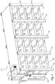
- Fig. 1 shows a storage system 10, which is designed to accommodate vehicle drive batteries 100.
- vehicle drive batteries 100 are comparatively large battery modules with a size of at least 150 cm x 100 cm x 20 cm, which are temporarily stored in a storage system 10 of the type shown and described below, in particular in the area of vehicle assembly, in order from here to the To be installed in vehicles.
- the storage system 10 has a total of 16 storage areas 90, each of which is provided for receiving a battery module in the form of a vehicle drive battery 100 of the type described above. These 16 areas in total are arranged in the form of horizontal and vertical rows of four storage areas 90 each.
- a ventilation system is provided, which will be explained below and for which an already in Fig. 1
- the main gas discharge duct 64, a cooling device 132 and a conveying device 134 can be seen.
- a central control unit 120 is provided at the end of the shelf system.
- a flow sensor 85 is provided, which is shown in FIG Fig. 3 and which makes it possible to see whether the conveyor 132 is operating as expected. It can be a pressure difference sensor, for example.
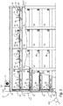
- Fig. 2 shows the bearing system 10 of FIG. 10 again with the upper cover plate removed for the purpose of clarification Fig. 1 .
- the storage system 10 is formed from a plurality of vertical columns in the form of hollow profiles, to which intermediate floors 40 are attached.
- the storage areas 90 are separated from one another by partition walls 24.
- the storage areas 90 are delimited by walls 25, 26 on the left-hand and right-hand sides and on the rear.
- Each storage area 90 has a charging connection 102 and a data interface 104.
- Vehicle drive batteries 100 can be charged in the stored state via the charging connection 102 and a cable (not shown) provided for this purpose, or it can be prevented that the desired minimum charge is not reached.
- Vehicle drive batteries 100 or receptacles 101 for receiving vehicle drive batteries can also be connected to central control unit 120 via data interface 104 and a cable (not shown). This makes it possible for the sensors integrated in removable receptacles or in the vehicle drive batteries themselves to provide additional data for the central control unit 120, for example temperature data or charge status data.
- the support base 42 which delimits the bearing areas 90 at the bottom, is each provided with a gas outlet 60 which can be opened, narrowed or closed with respect to the bearing area 90 by a throttle 72 designed as an adjustable grille.
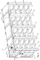
- Fig. 3 the ventilation system starting from the gas outlets 60 can be clearly seen in the cut area.
- the gas outlets 60 each open into a common gas discharge channel 62, which is arranged within the intermediate floors 40 designed as a double floor.
- these common gas discharge channels 62 are delimited on the one hand by a ceiling floor 46 that closes the storage areas 90 at the top and on the other hand by a support base 42 that closes the storage areas 90 at the bottom.
- these common gas discharge channels 62 open into a main gas discharge channel 64, which in turn is connected to the cooling device 132 and the conveying device 134.
- Air is sucked in from the main gas discharge duct 64 by the conveying device 134, so that air is also drawn in indirectly from the common gas discharge ducts 62 and thus from the storage areas 90.
- a plurality of sensors is provided in the ventilation system, the arrangement described below being to be understood as an example and a large number of variations in this regard being conceivable.
- a temperature sensor 80 is assigned to each gas outlet 60 of the bearing areas 90, by means of which the air flowing out here is measured.
- the temperature sensor 80 is arranged in such a way that the temperature value detected by it is influenced exclusively or predominantly by the air flowing out of the respective bearing area 90 through the gas outlet 60.
- Gas analysis sensors 82 which measure the composition of the gas flowing past are provided in the common gas discharge channels 62. Furthermore, supplementary common temperature sensors 83 are provided here.
- the main gas discharge channel 64 also has a supplementary gas analysis sensor 84.
- a further sensor 86 in the form of a thermal imaging camera 87 is provided at the front end of each free area 50 delimited by the support base 42 and the ceiling bases 46. This thermal imaging camera 87 is aligned such that it overlooks the supporting floors below four storage areas and / or the ceiling floors above four storage areas 90 along the free area 50 and can determine a temperature change here in a differentiable manner according to the storage area.
- the data from all sensors 80, 82, 83, 84, 86, 87 are fed to the central control unit 120 via a line system (not shown), the lines of which are preferably also arranged in the free areas 50.
- the central control unit 120 can be connected to a control center 124 via a line 122, so that faults can be passed on to this control center 124 if necessary.
- the control unit 120 is designed to influence the operating parameters of the storage system 10 in various ways if the data from the sensors make this recognizable as necessary.
- a temperature increase at the sensors 80 can make it possible to detect that a vehicle drive battery 100 heats up considerably during charging. If the temperature rise is very high or if neighboring sensors report a temperature rise, this can be identified as a possible fire.
- the gas analysis sensors 82 and 84 can be used to determine whether an unusual concentration of a gas leaking from a vehicle drive battery 100 is observed.
- throttles 74 designed as flaps can be adjusted at the ends of the common gas discharge channels 62 in order to increase or decrease the gas discharge from a storage area or a series of storage areas. If the throttles 72 are designed with a servomotor, it may also be possible to individually increase or decrease the gas discharge from individual storage areas.
- the central control unit 120 can influence which gas is to be removed from the storage areas 90 as a whole. In combination with the aforementioned controllability of the throttles 72, 74, the ventilation can thus be controlled individually for each storage area.
- the central control unit can also reduce or increase the charging current that is output via the charging connection 102 in the light of sensor data.
- a central sprinkling system or decentralized sprinkling systems which can also be connected to the central control unit 120 and allow fire-fighting measures to be initiated immediately in a fire that has been identified, recognizable by certain outgassing or temperature increases.
- Fig. 4 shows an alternative variant of the storage system 10, which differs from the design of FIG Figs. 1 to 3 differs:
- a plurality of common vertical gas discharge channels 65 are provided, to which a plurality of storage areas 90 of a vertical row are connected.
- the common vertical gas discharge channels 65 open into a common main gas discharge channel 66.
- all storage areas 90 are preferably each connected to two common gas discharge channels 62, 65, one vertical and one horizontal.
- each of the vertical common gas discharge channels 65 is assigned a sensor 86, which can primarily be a gas analysis sensor and / or a temperature sensor.
- This arrangement makes it possible, with a comparatively small number of sensors, namely at least the sum of the number of vertical and horizontal rows of storage areas, to be able to precisely assign changes in state. If values indicating a malfunction are determined both in a vertical gas discharge channel 65 and in a horizontal gas discharge channel 62, the cause for this is presumably to be found at the intersection of the affected vertical row and the affected horizontal row.
- This precise localization makes it possible to take targeted measures, for example to specifically regulate the air supply or air discharge to the affected storage area by setting the throttles 72, 74. If a potentially catastrophic situation is determined, for example a fire or the leakage of gas from one of the batteries, further measures can also be carried out on the basis of the localization, such as in particular the targeted initiation of an extinguishing process or the manual or automated removal of the affected battery from the Storage area and the transfer to a safe area.
- the mentioned common vertical gas discharge channels 65 and the main gas discharge channel 66 are provided in a manner not shown, similar to the common horizontal gas discharge channels 62 and the main gas discharge channel 64, with throttles, that is to say manually or automatically controllable throttles, which are located in the area of openings in the back wall 26 between the storage areas 90 on the one hand and the common vertical gas discharge channels 65 are arranged on the other hand and / or which are provided between the common vertical gas discharge channels 65 on the one hand and the main gas discharge channel 66 on the other hand.
- the channels 65 and 66 can also be designed as pure sensor channels that manage without throttles and that do not serve to discharge gas to influence the bearing area, but only for the localization described. In this case, the throttles can be dispensed with.
Landscapes
- Engineering & Computer Science (AREA)
- Chemical & Material Sciences (AREA)
- Chemical Kinetics & Catalysis (AREA)
- Electrochemistry (AREA)
- General Chemical & Material Sciences (AREA)
- Power Engineering (AREA)
- Manufacturing & Machinery (AREA)
- Transportation (AREA)
- Mechanical Engineering (AREA)
- Life Sciences & Earth Sciences (AREA)
- Sustainable Development (AREA)
- Sustainable Energy (AREA)
- Battery Mounting, Suspending (AREA)
- Secondary Cells (AREA)
- Arrangement Or Mounting Of Propulsion Units For Vehicles (AREA)
Priority Applications (1)
| Application Number | Priority Date | Filing Date | Title |
|---|---|---|---|
| PL18168792T PL3401977T3 (pl) | 2017-05-08 | 2018-04-23 | Stacjonarny system magazynowania akumulatorów |
Applications Claiming Priority (1)
| Application Number | Priority Date | Filing Date | Title |
|---|---|---|---|
| DE102017207691.7A DE102017207691B4 (de) | 2017-05-08 | 2017-05-08 | Stationäres Lagersystem für Batterien |
Publications (2)
| Publication Number | Publication Date |
|---|---|
| EP3401977A1 EP3401977A1 (de) | 2018-11-14 |
| EP3401977B1 true EP3401977B1 (de) | 2021-03-17 |
Family
ID=62148100
Family Applications (1)
| Application Number | Title | Priority Date | Filing Date |
|---|---|---|---|
| EP18168792.2A Active EP3401977B1 (de) | 2017-05-08 | 2018-04-23 | Stationäres lagersystem für batterien |
Country Status (4)
| Country | Link |
|---|---|
| EP (1) | EP3401977B1 (pl) |
| DE (1) | DE102017207691B4 (pl) |
| ES (1) | ES2875741T3 (pl) |
| PL (1) | PL3401977T3 (pl) |
Families Citing this family (23)
| Publication number | Priority date | Publication date | Assignee | Title |
|---|---|---|---|---|
| CN109480554A (zh) * | 2018-12-13 | 2019-03-19 | 启迪桑德环境资源股份有限公司 | 负压隔离式货架 |
| CN110127253A (zh) * | 2019-04-20 | 2019-08-16 | 中山市四海智能装备有限公司 | 一种锂电池高温静置立库温度独立控制装置及方法 |
| DE102019208801B3 (de) * | 2019-06-18 | 2020-09-03 | Volkswagen Aktiengesellschaft | Verbinden von Batteriemodulen bei elektrischen Energiespeichern von Kraftfahrzeugen |
| CN110931408A (zh) * | 2019-11-21 | 2020-03-27 | 成都晔凡科技有限公司 | 工具车组件及其使用方法 |
| CN111392309B (zh) * | 2020-04-21 | 2024-09-24 | 浙江瀚镪自动化设备股份有限公司 | 一种便于取物的自动货架 |
| DE102020111987B4 (de) * | 2020-05-04 | 2024-06-27 | Kraftanlagen Energies & Services Se | Heizeinrichtung |
| CN111509164B (zh) * | 2020-05-26 | 2022-04-22 | 重庆工业职业技术学院 | 一种新能源汽车用电池存放装置 |
| CN111516537A (zh) * | 2020-06-04 | 2020-08-11 | 童恬 | 一种充电桩 |
| CN113183821A (zh) * | 2021-05-14 | 2021-07-30 | 郑州宜家安好软件科技有限公司 | 一种电池更换装置、方法、电子设备及存储介质 |
| CN115503544A (zh) * | 2021-06-22 | 2022-12-23 | 金茂智慧交通科技(天津)有限公司 | 集成式换电装置 |
| CN113733951A (zh) * | 2021-09-18 | 2021-12-03 | 博众精工科技股份有限公司 | 一种充电架及充换电站 |
| DE102021005416A1 (de) | 2021-11-02 | 2021-12-16 | Daimler Ag | Regalvorrichtung zum Abstellen von zumindest einem elektrischen Energiespeicher eines Kraftfahrzeugs sowie Batterispeichersystem |
| KR102924482B1 (ko) * | 2022-06-03 | 2026-02-05 | 주식회사 엘지에너지솔루션 | 배터리 컨테이너 및 이를 포함하는 에너지 저장 시스템 |
| CN115072238A (zh) * | 2022-06-24 | 2022-09-20 | 广州明珞装备股份有限公司 | 一种多工位加热立库及输送线 |
| CN217745449U (zh) * | 2022-08-18 | 2022-11-08 | 宁德时代新能源科技股份有限公司 | 仓储系统 |
| DE102022123722A1 (de) | 2022-09-16 | 2024-03-21 | Rhenus Automotive SE | Stapelbares Logistikmodul für Alkali-Ionenbatterien |
| CN115570999A (zh) * | 2022-09-30 | 2023-01-06 | 协鑫电港云科技(海南)有限公司 | 基于换电站的通风控制方法、装置、换电站、设备及介质 |
| DE102023001227A1 (de) | 2023-03-29 | 2024-10-02 | Mercedes-Benz Group AG | Regalvorrichtung zum Abstellen von zumindest einem elektrischen Energiespeicher eines Kraftfahrzeugs sowie Batteriespeichersystem |
| DE102023116883A1 (de) * | 2023-06-27 | 2024-07-18 | Audi Aktiengesellschaft | Behälter für Lagerung und Transport von mindestens einer Hochvoltbatterie |
| CN119756600A (zh) * | 2024-07-08 | 2025-04-04 | 比亚迪股份有限公司 | 锂电池仓储温度监测系统 |
| EP4697442A1 (de) * | 2024-08-14 | 2026-02-18 | Siemens Schweiz AG | Thermische überwachung von lithium- oder natrium-ionen-antriebsbatterien in einem regallagersystem über eine fahrzeugbus- oder on-board-diagnoseschnittstelle |
| CN119581776B (zh) * | 2025-01-24 | 2025-07-15 | 长垣市云明新能源科技有限公司 | 用于储能电源温控调节的电池仓及其电池模组 |
| CN120922501B (zh) * | 2025-07-30 | 2026-03-17 | 嘉能嘉特医食品(山东)有限公司 | 一种自动化立体仓库用货物堆码装置 |
Family Cites Families (16)
| Publication number | Priority date | Publication date | Assignee | Title |
|---|---|---|---|---|
| SE372848B (pl) | 1973-11-05 | 1975-01-13 | Ardo Ab | |
| GB9722890D0 (en) * | 1997-10-31 | 1998-01-07 | Brook Chrispin Kenneth | Battery charging rack |
| US7286356B2 (en) | 2004-04-15 | 2007-10-23 | Telect, Inc. | Thermally insulated cabinet and method for inhibiting heat transfer |
| KR100778435B1 (ko) * | 2005-07-05 | 2007-11-21 | 삼성에스디아이 주식회사 | 전지 모듈 소화 시스템 |
| US7838142B2 (en) | 2006-02-09 | 2010-11-23 | Scheucher Karl F | Scalable intelligent power supply system and method |
| JP4940203B2 (ja) * | 2008-08-29 | 2012-05-30 | 株式会社日立製作所 | 鉄道車両の電池箱及び鉄道車両 |
| KR101057556B1 (ko) * | 2010-02-03 | 2011-08-17 | 에스비리모티브 주식회사 | 배터리 시스템 및 그 구동 방법 |
| SE535903C2 (sv) | 2011-03-17 | 2013-02-12 | Sitetel Sweden Ab | Gasavlägsningsmodul för batteriskåp |
| WO2013080385A1 (ja) * | 2011-12-02 | 2013-06-06 | 株式会社日立製作所 | 電池システム |
| EP2797158A1 (en) * | 2012-02-08 | 2014-10-29 | Hitachi, Ltd. | Cell system |
| IL218923A (en) | 2012-03-29 | 2016-12-29 | Better Place GmbH | Battery service system for electric vehicle |
| JPWO2014073524A1 (ja) * | 2012-11-06 | 2016-09-08 | Necエンジニアリング株式会社 | 電池シェルフアセンブリ、蓄電システム、および電池シェルフアセンブリの組立方法 |
| DE102012222787A1 (de) * | 2012-12-11 | 2014-03-27 | Robert Bosch Gmbh | Energiespeichersystem und Verfahren zum Überwachen des Ruhezustands eines Energiespeichersystems |
| US9566954B2 (en) * | 2014-03-10 | 2017-02-14 | Max Moskowitz | Vehicular accessory |
| US9688252B2 (en) | 2014-04-23 | 2017-06-27 | Tesla, Inc. | Battery swapping system and techniques |
| EP2975919A1 (en) | 2014-07-14 | 2016-01-20 | Alcatel Lucent | A cabinet for housing electric and/or electronic components |
-
2017
- 2017-05-08 DE DE102017207691.7A patent/DE102017207691B4/de active Active
-
2018
- 2018-04-23 PL PL18168792T patent/PL3401977T3/pl unknown
- 2018-04-23 ES ES18168792T patent/ES2875741T3/es active Active
- 2018-04-23 EP EP18168792.2A patent/EP3401977B1/de active Active
Non-Patent Citations (1)
| Title |
|---|
| None * |
Also Published As
| Publication number | Publication date |
|---|---|
| PL3401977T3 (pl) | 2021-10-04 |
| DE102017207691A1 (de) | 2018-11-08 |
| ES2875741T3 (es) | 2021-11-11 |
| DE102017207691B4 (de) | 2026-03-12 |
| EP3401977A1 (de) | 2018-11-14 |
Similar Documents
| Publication | Publication Date | Title |
|---|---|---|
| EP3401977B1 (de) | Stationäres lagersystem für batterien | |
| DE102013222301B4 (de) | Filteranlage zum Abscheiden von Verunreinigungen aus einem Verunreinigungen enthaltenden Rohgasstrom, Lackieranlage und Verfahren zum Abscheiden von Verunreinigungen aus einem Verunreinigungen enthaltenden Rohgasstrom | |
| DE202007019005U1 (de) | System zur Klimatisierungsregelung | |
| EP2874880B1 (de) | Kühlkonzept rückpaneel | |
| EP0065248A1 (de) | Hochtemperaturbatterie | |
| WO2021228934A1 (de) | Modulares zuchtsystem für insekten | |
| EP3221647B1 (de) | Anordnung umfassend einen innenraum und eine lüftungsanlage und verfahren zum klimatisieren eines innenraums mit einer solchen lüftungsanlage | |
| DE202015105378U1 (de) | Filter- und Filterwechselvorrichtung | |
| DE102017009686A1 (de) | Klimakammer zur Prüfung von E-Mobilitäts-Hochvolt-Batterien, Brennstoffzellen oder anderen Energiespeichern oder damit ausgerüsteten oder verbunden Antriebseinheiten mit gefährlichem Energieinhalt | |
| DE102010060824B4 (de) | Vorrichtung zur Handhabung von Objektträgern mit einer Ausgabeschublade | |
| EP4421420A1 (de) | Temperiersystem und verfahren zu dessen steuerung | |
| EP3059528B1 (de) | Kühllager und verfahren zum betrieb eines solchen kühllagers | |
| EP3247496B1 (de) | Abzugsvorrichtung mit geregelter absaugeinrichtung | |
| EP2088012B1 (de) | Ladegerät für eine Batterie eines Fahrzeugs | |
| EP2033545A2 (de) | Verfahren und Vorrichtung zur Klimatisierung einer Vitrine | |
| DE102022123722A1 (de) | Stapelbares Logistikmodul für Alkali-Ionenbatterien | |
| EP2201304B1 (de) | Lageranordnung mit vorgebbarer lagerungsatmosphäre | |
| DE202008013740U1 (de) | Backofen | |
| DE102024131957B3 (de) | Stapelbare Lagerwanne für Batterien mit großer Ladekapazität | |
| EP2899798B1 (de) | Batteriesystem für ein Kraftfahrzeug | |
| DE102015106718A1 (de) | Vorrichtung zur Behandlung von schädlichen Abgasen aus einer Vakuum-Prozessanlage | |
| DE102007013498B4 (de) | Adsorptionsvorrichtung sowie Anlage zur Adsorption hochtoxischer Substanzen aus der Abluft von Chemieprozessanlagen | |
| DE102016104491A1 (de) | Vorrichtung für die Ventilationssteuerung in Trockenöfen | |
| DE2734018A1 (de) | Backofen fuer das baeckereigewerbe mit einschiebbarem schragen | |
| DE102017110510B4 (de) | Mobiler Container |
Legal Events
| Date | Code | Title | Description |
|---|---|---|---|
| PUAI | Public reference made under article 153(3) epc to a published international application that has entered the european phase |
Free format text: ORIGINAL CODE: 0009012 |
|
| STAA | Information on the status of an ep patent application or granted ep patent |
Free format text: STATUS: THE APPLICATION HAS BEEN PUBLISHED |
|
| AK | Designated contracting states |
Kind code of ref document: A1 Designated state(s): AL AT BE BG CH CY CZ DE DK EE ES FI FR GB GR HR HU IE IS IT LI LT LU LV MC MK MT NL NO PL PT RO RS SE SI SK SM TR |
|
| AX | Request for extension of the european patent |
Extension state: BA ME |
|
| STAA | Information on the status of an ep patent application or granted ep patent |
Free format text: STATUS: REQUEST FOR EXAMINATION WAS MADE |
|
| 17P | Request for examination filed |
Effective date: 20190513 |
|
| RBV | Designated contracting states (corrected) |
Designated state(s): AL AT BE BG CH CY CZ DE DK EE ES FI FR GB GR HR HU IE IS IT LI LT LU LV MC MK MT NL NO PL PT RO RS SE SI SK SM TR |
|
| REG | Reference to a national code |
Ref country code: DE Ref legal event code: R079 Ref document number: 502018004311 Country of ref document: DE Free format text: PREVIOUS MAIN CLASS: H01M0002100000 Ipc: B60L0050600000 |
|
| GRAP | Despatch of communication of intention to grant a patent |
Free format text: ORIGINAL CODE: EPIDOSNIGR1 |
|
| STAA | Information on the status of an ep patent application or granted ep patent |
Free format text: STATUS: GRANT OF PATENT IS INTENDED |
|
| RIC1 | Information provided on ipc code assigned before grant |
Ipc: B60L 50/60 20190101AFI20201103BHEP Ipc: H01M 10/613 20140101ALI20201103BHEP Ipc: H01M 10/44 20060101ALI20201103BHEP Ipc: H01M 10/6555 20140101ALI20201103BHEP Ipc: H01M 2/10 20060101ALI20201103BHEP Ipc: B60L 58/13 20190101ALI20201103BHEP Ipc: H01M 10/48 20060101ALI20201103BHEP Ipc: H02J 7/00 20060101ALI20201103BHEP Ipc: B60L 53/80 20190101ALI20201103BHEP Ipc: B60L 50/64 20190101ALI20201103BHEP Ipc: H01M 10/625 20140101ALI20201103BHEP Ipc: H01M 10/6557 20140101ALI20201103BHEP |
|
| INTG | Intention to grant announced |
Effective date: 20201202 |
|
| GRAS | Grant fee paid |
Free format text: ORIGINAL CODE: EPIDOSNIGR3 |
|
| GRAA | (expected) grant |
Free format text: ORIGINAL CODE: 0009210 |
|
| STAA | Information on the status of an ep patent application or granted ep patent |
Free format text: STATUS: THE PATENT HAS BEEN GRANTED |
|
| AK | Designated contracting states |
Kind code of ref document: B1 Designated state(s): AL AT BE BG CH CY CZ DE DK EE ES FI FR GB GR HR HU IE IS IT LI LT LU LV MC MK MT NL NO PL PT RO RS SE SI SK SM TR |
|
| REG | Reference to a national code |
Ref country code: DE Ref legal event code: R082 Ref document number: 502018004311 Country of ref document: DE Representative=s name: PATENTANWALTSKANZLEI CARTAGENA PARTNERSCHAFTSG, DE Ref country code: GB Ref legal event code: FG4D Free format text: NOT ENGLISH |
|
| REG | Reference to a national code |
Ref country code: CH Ref legal event code: EP |
|
| REG | Reference to a national code |
Ref country code: DE Ref legal event code: R096 Ref document number: 502018004311 Country of ref document: DE |
|
| REG | Reference to a national code |
Ref country code: IE Ref legal event code: FG4D Free format text: LANGUAGE OF EP DOCUMENT: GERMAN |
|
| REG | Reference to a national code |
Ref country code: AT Ref legal event code: REF Ref document number: 1371920 Country of ref document: AT Kind code of ref document: T Effective date: 20210415 |
|
| REG | Reference to a national code |
Ref country code: DE Ref legal event code: R082 Ref document number: 502018004311 Country of ref document: DE Representative=s name: PATENTANWALTSKANZLEI CARTAGENA PARTNERSCHAFTSG, DE Ref country code: DE Ref legal event code: R081 Ref document number: 502018004311 Country of ref document: DE Owner name: FRITZ GMBH & CO. KG, DE Free format text: FORMER OWNER: FRITZ GMBH. & CO. KG, 74193 SCHWAIGERN, DE |
|
| REG | Reference to a national code |
Ref country code: LT Ref legal event code: MG9D |
|
| PG25 | Lapsed in a contracting state [announced via postgrant information from national office to epo] |
Ref country code: BG Free format text: LAPSE BECAUSE OF FAILURE TO SUBMIT A TRANSLATION OF THE DESCRIPTION OR TO PAY THE FEE WITHIN THE PRESCRIBED TIME-LIMIT Effective date: 20210617 Ref country code: FI Free format text: LAPSE BECAUSE OF FAILURE TO SUBMIT A TRANSLATION OF THE DESCRIPTION OR TO PAY THE FEE WITHIN THE PRESCRIBED TIME-LIMIT Effective date: 20210317 Ref country code: HR Free format text: LAPSE BECAUSE OF FAILURE TO SUBMIT A TRANSLATION OF THE DESCRIPTION OR TO PAY THE FEE WITHIN THE PRESCRIBED TIME-LIMIT Effective date: 20210317 Ref country code: GR Free format text: LAPSE BECAUSE OF FAILURE TO SUBMIT A TRANSLATION OF THE DESCRIPTION OR TO PAY THE FEE WITHIN THE PRESCRIBED TIME-LIMIT Effective date: 20210618 Ref country code: NO Free format text: LAPSE BECAUSE OF FAILURE TO SUBMIT A TRANSLATION OF THE DESCRIPTION OR TO PAY THE FEE WITHIN THE PRESCRIBED TIME-LIMIT Effective date: 20210617 |
|
| REG | Reference to a national code |
Ref country code: NL Ref legal event code: MP Effective date: 20210317 |
|
| PG25 | Lapsed in a contracting state [announced via postgrant information from national office to epo] |
Ref country code: SE Free format text: LAPSE BECAUSE OF FAILURE TO SUBMIT A TRANSLATION OF THE DESCRIPTION OR TO PAY THE FEE WITHIN THE PRESCRIBED TIME-LIMIT Effective date: 20210317 Ref country code: LV Free format text: LAPSE BECAUSE OF FAILURE TO SUBMIT A TRANSLATION OF THE DESCRIPTION OR TO PAY THE FEE WITHIN THE PRESCRIBED TIME-LIMIT Effective date: 20210317 Ref country code: RS Free format text: LAPSE BECAUSE OF FAILURE TO SUBMIT A TRANSLATION OF THE DESCRIPTION OR TO PAY THE FEE WITHIN THE PRESCRIBED TIME-LIMIT Effective date: 20210317 |
|
| PGFP | Annual fee paid to national office [announced via postgrant information from national office to epo] |
Ref country code: IE Payment date: 20210630 Year of fee payment: 4 |
|
| PG25 | Lapsed in a contracting state [announced via postgrant information from national office to epo] |
Ref country code: NL Free format text: LAPSE BECAUSE OF FAILURE TO SUBMIT A TRANSLATION OF THE DESCRIPTION OR TO PAY THE FEE WITHIN THE PRESCRIBED TIME-LIMIT Effective date: 20210317 |
|
| PG25 | Lapsed in a contracting state [announced via postgrant information from national office to epo] |
Ref country code: SM Free format text: LAPSE BECAUSE OF FAILURE TO SUBMIT A TRANSLATION OF THE DESCRIPTION OR TO PAY THE FEE WITHIN THE PRESCRIBED TIME-LIMIT Effective date: 20210317 Ref country code: LT Free format text: LAPSE BECAUSE OF FAILURE TO SUBMIT A TRANSLATION OF THE DESCRIPTION OR TO PAY THE FEE WITHIN THE PRESCRIBED TIME-LIMIT Effective date: 20210317 Ref country code: EE Free format text: LAPSE BECAUSE OF FAILURE TO SUBMIT A TRANSLATION OF THE DESCRIPTION OR TO PAY THE FEE WITHIN THE PRESCRIBED TIME-LIMIT Effective date: 20210317 |
|
| REG | Reference to a national code |
Ref country code: ES Ref legal event code: FG2A Ref document number: 2875741 Country of ref document: ES Kind code of ref document: T3 Effective date: 20211111 |
|
| PG25 | Lapsed in a contracting state [announced via postgrant information from national office to epo] |
Ref country code: PT Free format text: LAPSE BECAUSE OF FAILURE TO SUBMIT A TRANSLATION OF THE DESCRIPTION OR TO PAY THE FEE WITHIN THE PRESCRIBED TIME-LIMIT Effective date: 20210719 Ref country code: SK Free format text: LAPSE BECAUSE OF FAILURE TO SUBMIT A TRANSLATION OF THE DESCRIPTION OR TO PAY THE FEE WITHIN THE PRESCRIBED TIME-LIMIT Effective date: 20210317 Ref country code: RO Free format text: LAPSE BECAUSE OF FAILURE TO SUBMIT A TRANSLATION OF THE DESCRIPTION OR TO PAY THE FEE WITHIN THE PRESCRIBED TIME-LIMIT Effective date: 20210317 Ref country code: IS Free format text: LAPSE BECAUSE OF FAILURE TO SUBMIT A TRANSLATION OF THE DESCRIPTION OR TO PAY THE FEE WITHIN THE PRESCRIBED TIME-LIMIT Effective date: 20210717 |
|
| REG | Reference to a national code |
Ref country code: DE Ref legal event code: R097 Ref document number: 502018004311 Country of ref document: DE |
|
| PG25 | Lapsed in a contracting state [announced via postgrant information from national office to epo] |
Ref country code: LU Free format text: LAPSE BECAUSE OF NON-PAYMENT OF DUE FEES Effective date: 20210423 |
|
| REG | Reference to a national code |
Ref country code: BE Ref legal event code: MM Effective date: 20210430 |
|
| PLBE | No opposition filed within time limit |
Free format text: ORIGINAL CODE: 0009261 |
|
| STAA | Information on the status of an ep patent application or granted ep patent |
Free format text: STATUS: NO OPPOSITION FILED WITHIN TIME LIMIT |
|
| PG25 | Lapsed in a contracting state [announced via postgrant information from national office to epo] |
Ref country code: AL Free format text: LAPSE BECAUSE OF FAILURE TO SUBMIT A TRANSLATION OF THE DESCRIPTION OR TO PAY THE FEE WITHIN THE PRESCRIBED TIME-LIMIT Effective date: 20210317 Ref country code: CH Free format text: LAPSE BECAUSE OF NON-PAYMENT OF DUE FEES Effective date: 20210430 Ref country code: DK Free format text: LAPSE BECAUSE OF FAILURE TO SUBMIT A TRANSLATION OF THE DESCRIPTION OR TO PAY THE FEE WITHIN THE PRESCRIBED TIME-LIMIT Effective date: 20210317 Ref country code: MC Free format text: LAPSE BECAUSE OF FAILURE TO SUBMIT A TRANSLATION OF THE DESCRIPTION OR TO PAY THE FEE WITHIN THE PRESCRIBED TIME-LIMIT Effective date: 20210317 Ref country code: LI Free format text: LAPSE BECAUSE OF NON-PAYMENT OF DUE FEES Effective date: 20210430 |
|
| 26N | No opposition filed |
Effective date: 20211220 |
|
| PG25 | Lapsed in a contracting state [announced via postgrant information from national office to epo] |
Ref country code: SI Free format text: LAPSE BECAUSE OF FAILURE TO SUBMIT A TRANSLATION OF THE DESCRIPTION OR TO PAY THE FEE WITHIN THE PRESCRIBED TIME-LIMIT Effective date: 20210317 |
|
| REG | Reference to a national code |
Ref country code: DE Ref legal event code: R082 Ref document number: 502018004311 Country of ref document: DE Representative=s name: LBP LEMCKE, BROMMER & PARTNER PATENTANWAELTE M, DE Ref country code: DE Ref legal event code: R082 Ref document number: 502018004311 Country of ref document: DE Representative=s name: WITTE, WELLER & PARTNER PATENTANWAELTE MBB, DE |
|
| PG25 | Lapsed in a contracting state [announced via postgrant information from national office to epo] |
Ref country code: IS Free format text: LAPSE BECAUSE OF FAILURE TO SUBMIT A TRANSLATION OF THE DESCRIPTION OR TO PAY THE FEE WITHIN THE PRESCRIBED TIME-LIMIT Effective date: 20210717 |
|
| PG25 | Lapsed in a contracting state [announced via postgrant information from national office to epo] |
Ref country code: BE Free format text: LAPSE BECAUSE OF NON-PAYMENT OF DUE FEES Effective date: 20210430 |
|
| PG25 | Lapsed in a contracting state [announced via postgrant information from national office to epo] |
Ref country code: IE Free format text: LAPSE BECAUSE OF NON-PAYMENT OF DUE FEES Effective date: 20220423 |
|
| P01 | Opt-out of the competence of the unified patent court (upc) registered |
Effective date: 20230502 |
|
| REG | Reference to a national code |
Ref country code: DE Ref legal event code: R082 Ref document number: 502018004311 Country of ref document: DE Representative=s name: LBP LEMCKE, BROMMER & PARTNER PATENTANWAELTE M, DE |
|
| PG25 | Lapsed in a contracting state [announced via postgrant information from national office to epo] |
Ref country code: CY Free format text: LAPSE BECAUSE OF FAILURE TO SUBMIT A TRANSLATION OF THE DESCRIPTION OR TO PAY THE FEE WITHIN THE PRESCRIBED TIME-LIMIT Effective date: 20210317 |
|
| PG25 | Lapsed in a contracting state [announced via postgrant information from national office to epo] |
Ref country code: HU Free format text: LAPSE BECAUSE OF FAILURE TO SUBMIT A TRANSLATION OF THE DESCRIPTION OR TO PAY THE FEE WITHIN THE PRESCRIBED TIME-LIMIT; INVALID AB INITIO Effective date: 20180423 |
|
| PG25 | Lapsed in a contracting state [announced via postgrant information from national office to epo] |
Ref country code: MK Free format text: LAPSE BECAUSE OF FAILURE TO SUBMIT A TRANSLATION OF THE DESCRIPTION OR TO PAY THE FEE WITHIN THE PRESCRIBED TIME-LIMIT Effective date: 20210317 |
|
| REG | Reference to a national code |
Ref country code: AT Ref legal event code: MM01 Ref document number: 1371920 Country of ref document: AT Kind code of ref document: T Effective date: 20230423 |
|
| PG25 | Lapsed in a contracting state [announced via postgrant information from national office to epo] |
Ref country code: AT Free format text: LAPSE BECAUSE OF NON-PAYMENT OF DUE FEES Effective date: 20230423 |
|
| PG25 | Lapsed in a contracting state [announced via postgrant information from national office to epo] |
Ref country code: AT Free format text: LAPSE BECAUSE OF NON-PAYMENT OF DUE FEES Effective date: 20230423 |
|
| PG25 | Lapsed in a contracting state [announced via postgrant information from national office to epo] |
Ref country code: MT Free format text: LAPSE BECAUSE OF FAILURE TO SUBMIT A TRANSLATION OF THE DESCRIPTION OR TO PAY THE FEE WITHIN THE PRESCRIBED TIME-LIMIT Effective date: 20210317 |
|
| PGFP | Annual fee paid to national office [announced via postgrant information from national office to epo] |
Ref country code: DE Payment date: 20250314 Year of fee payment: 8 Ref country code: PL Payment date: 20250410 Year of fee payment: 8 |
|
| PGFP | Annual fee paid to national office [announced via postgrant information from national office to epo] |
Ref country code: ES Payment date: 20250519 Year of fee payment: 8 |
|
| PGFP | Annual fee paid to national office [announced via postgrant information from national office to epo] |
Ref country code: IT Payment date: 20250430 Year of fee payment: 8 |
|
| PGFP | Annual fee paid to national office [announced via postgrant information from national office to epo] |
Ref country code: FR Payment date: 20250422 Year of fee payment: 8 |
|
| PGFP | Annual fee paid to national office [announced via postgrant information from national office to epo] |
Ref country code: CZ Payment date: 20250410 Year of fee payment: 8 |
|
| PG25 | Lapsed in a contracting state [announced via postgrant information from national office to epo] |
Ref country code: TR Free format text: LAPSE BECAUSE OF FAILURE TO SUBMIT A TRANSLATION OF THE DESCRIPTION OR TO PAY THE FEE WITHIN THE PRESCRIBED TIME-LIMIT Effective date: 20210317 |
|
| PGFP | Annual fee paid to national office [announced via postgrant information from national office to epo] |
Ref country code: GB Payment date: 20260327 Year of fee payment: 9 |
|
| PGFP | Annual fee paid to national office [announced via postgrant information from national office to epo] |
Ref country code: AT Payment date: 20260410 Year of fee payment: 5 |