EP3401160A1 - Tendeur de sangle - Google Patents
Tendeur de sangle Download PDFInfo
- Publication number
- EP3401160A1 EP3401160A1 EP18171629.1A EP18171629A EP3401160A1 EP 3401160 A1 EP3401160 A1 EP 3401160A1 EP 18171629 A EP18171629 A EP 18171629A EP 3401160 A1 EP3401160 A1 EP 3401160A1
- Authority
- EP
- European Patent Office
- Prior art keywords
- belt tensioner
- lever
- clamping lever
- base element
- side cheeks
- Prior art date
- Legal status (The legal status is an assumption and is not a legal conclusion. Google has not performed a legal analysis and makes no representation as to the accuracy of the status listed.)
- Granted
Links
- 238000007373 indentation Methods 0.000 claims description 5
- 239000002184 metal Substances 0.000 claims description 4
- 238000011161 development Methods 0.000 description 1
- 230000018109 developmental process Effects 0.000 description 1
- 230000001771 impaired effect Effects 0.000 description 1
- 238000004519 manufacturing process Methods 0.000 description 1
- 230000000284 resting effect Effects 0.000 description 1
Images


Classifications
-
- B—PERFORMING OPERATIONS; TRANSPORTING
- B25—HAND TOOLS; PORTABLE POWER-DRIVEN TOOLS; MANIPULATORS
- B25B—TOOLS OR BENCH DEVICES NOT OTHERWISE PROVIDED FOR, FOR FASTENING, CONNECTING, DISENGAGING OR HOLDING
- B25B25/00—Implements for fastening, connecting or tensioning of wire or strip
-
- B—PERFORMING OPERATIONS; TRANSPORTING
- B60—VEHICLES IN GENERAL
- B60P—VEHICLES ADAPTED FOR LOAD TRANSPORTATION OR TO TRANSPORT, TO CARRY, OR TO COMPRISE SPECIAL LOADS OR OBJECTS
- B60P7/00—Securing or covering of load on vehicles
- B60P7/06—Securing of load
- B60P7/08—Securing to the vehicle floor or sides
- B60P7/0823—Straps; Tighteners
- B60P7/0838—Tensioning by single movement of an actuating member
-
- A—HUMAN NECESSITIES
- A44—HABERDASHERY; JEWELLERY
- A44B—BUTTONS, PINS, BUCKLES, SLIDE FASTENERS, OR THE LIKE
- A44B11/00—Buckles; Similar fasteners for interconnecting straps or the like, e.g. for safety belts
- A44B11/02—Buckles; Similar fasteners for interconnecting straps or the like, e.g. for safety belts frictionally engaging surface of straps
- A44B11/06—Buckles; Similar fasteners for interconnecting straps or the like, e.g. for safety belts frictionally engaging surface of straps with clamping devices
- A44B11/12—Buckles; Similar fasteners for interconnecting straps or the like, e.g. for safety belts frictionally engaging surface of straps with clamping devices turnable clamp
- A44B11/125—Buckles; Similar fasteners for interconnecting straps or the like, e.g. for safety belts frictionally engaging surface of straps with clamping devices turnable clamp with strap tightening means
Definitions
- the invention relates to a belt tensioner formed from a U-shaped base member having a bottom and two side cheeks, and a pivotally mounted on the side cheeks of the base member from an open position to a closed position of the belt tensioner, U-shaped clamping lever with a handling tab and two side cheeks and a latching device in the closed position with the base element lockable locking device.
- Such belt tensioners for example, for tightening a tarpaulin of trucks, trailers, semitrailers for semitrailer tractors, railway cars or the like. are provided, are well known.
- a disadvantage of the known belt tensioners that they have a relatively complex mechanism for locking the clamping lever with the base member.
- the known belt tensioner for example, due to the use of spring elements for locking an increased effort, in particular for releasing the Verrieglung necessary.
- a belt tensioner comprising two pivotally interconnected plastic parts which are locked together in the closed state via a locking device.
- the locking device comprises two locking pieces, each comprising a pressure plate and a detent plate, which are interconnected via two webs, which webs are also formed on the lower part.
- the detent plate has a hook part, which passes through an integrally formed on the upper eyelet and engages behind this.
- the invention aims to remedy this situation.
- the invention has for its object to provide a belt tensioner of the specified genus, which is characterized by its simple structure and its small number of items, the locking device is robust and reliable and the force required in particular for releasing the locking of the clamping lever in the closed position is low.
- the locking device has an integrally formed on the base element latching lug on the same in the closed position of the belt tensioner a locking edge of the clamping lever when closing, wherein the locking edge for unlocking the clamping lever via an integrally formed on the clamping lever to the release lever Latch can be unlatched.
- integrally formed locking lug, the locking edge and the molded release lever here a belt tensioner is provided, which consists of a maximum of two parts, with unlocking of the clamping lever in the closed position is very simple and without increased effort by means of the release lever.
- the detent nose can either be arranged on one of the two side cheeks of the base element and the detent edge can be formed in a side cheek of the tensioning lever which runs parallel to the side cheek of the base element or can be arranged on a web extending parallel to one of the two side cheeks of the base element and the latching edge in an adjacent to the web of the base member parallel side cheek of the clamping lever be formed.
- the locking device has an integrally formed on the clamping lever locking lug which is latched in the closed position of the belt tensioner at a locking edge of the base member when closing the belt tensioner, wherein the locking lug for unlocking the clamping lever via an integrally formed on the clamping lever release lever on the Rastkante is unlatched.
- the locking lug can be arranged depending on the embodiment either on one of the two side cheeks of the clamping lever and the locking edge in an adjacent to the side cheek of the clamping lever parallel side cheek of the base member or the locking edge can at a distance parallel to one of the two side cheeks of Base element extending web disposed and the detent be formed in a adjacent to the web of the base member parallel side cheek of the clamping lever.
- a locking edge for example, serve an edge of a breakthrough.
- the handling tab of the clamping lever can be formed by a substantially U-shaped recess a resilient tab which can form the trigger lever for the clamping lever. Since the release lever is provided with its associated with the handling tab end near the side cheek of the clamping lever and arranged in extension to the locking lug or locking edge, the release lever can act directly on the side cheek and thus on the locking lug or locking edge, creating a simple unlocking of Clamping lever in the closed position is possible.
- the breakthrough or the detent having side cheek of the clamping lever can in the area between the provided at one end of the side cheek pivot axis for the clamping lever and the opening or the Latch have a recess, wherein between the recess and the front end of the clamping lever, a web may be formed, which may form a portion of the side cheek.
- the recess ensures that the relatively short web, in which the detent or the breakthrough is located, easier to move through the release lever.
- either the side cheeks of the clamping lever may overlap the side cheeks of the base member or the side cheeks of the base member overlap the side cheeks of the clamping lever.
- the side cheeks of the clamping lever By overlapping the side cheeks of the clamping lever on the side walls of the base member, the stability of the resting on the side cheeks of the base member clamping lever is increased, in particular upon actuation of the trigger lever.
- either the locking lug in the side wall of the base member or in the web of the base member or the latching lug in the side cheek of the clamping lever or in the web of the clamping lever may be formed by a depression.
- the indentation in the web of the base element or the clamping lever can be formed either by an L-shaped slot or by a U-shaped slot. Alternatively, the indentation can also be formed by an indentation or concavity introduced into the web.
- the pivot axis of the belt tensioner at one end of the tensioning lever may be formed by cylindrical tube-shaped projections integrally formed on the inner sides or on the outer sides of the side cheeks of the tensioning lever, which can be inserted and flanged into corresponding bores in the side cheeks of the base element.
- the two-part embodiment of the belt tensioner according to the invention enables automated production, since the base element and tensioning lever are designed as sheet metal stamped parts can be produced, wherein the pivot axis is formed by an integrated tubular exhibition of a part which engages through an opening of the other part and is subsequently crimped.
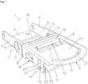
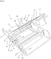
- the belt tensioner 1 is provided for tensioning a belt, the like on a tarpaulin of a truck, trailer, semitrailer tractor, railway wagons or the like. attacks, with a variety of belts and belt tensioners 1, the lower end of the tarpaulin or the like on a floor element. for example, the truck is clamped.
- the belt tensioner essentially comprises a U-shaped base element 2, which is formed from a bottom 3 and two side walls 4, 5, and one on the side walls 4, 5 of the base member 2 pivotally mounted from an open position to a closed position of the belt tensioner 1 .
- U-shaped clamping lever 6 with a handling tab 7 and also two side cheeks 8, 9.
- the side cheeks 4, 5 of the base element 2 may overlap the side cheeks 8, 9 of the tensioning lever 6 in a further embodiment, not shown, such that the side walls 4, 5 of the base element 2 engage over the side cheeks 8, 9 form substantially continuous edges formed by the side walls 4, 5 of the base member 2 outer edges.
- the base member and the clamping lever are each made as a one-piece sheet metal stamping.
- the belt tensioner 1 has a locking device 6 which can be locked to the tensioning lever 6 in the closed position with the base element 2, which will be discussed in more detail later.
- the pivot axis 11 of the belt tensioner 1 is formed by at one end of the clamping lever 6 to the side walls 8, 9 of the same molded cylindrical tube projections 12 which are inserted into corresponding holes 13 in the side walls 4, 5 of the base member 2 and flanged such that let the lugs 12 rotate in the holes 13 relatively free of play.
- the handling tab 7 of the tensioning lever 6 has a serving as a belt feedthrough opening 14, wherein the pivot axis 11 directed part of the handling tab 7 forms a holding web 15 for the belt, which is remote from the pivot axis 11 edge 16 for belt deflection in the direction of the pivot axis 11 folded over is.
- the bottom 3 of the base member 2 serving as a belt feedthrough opening 17 is also provided on the side facing away from the pivot axis 11 of the tensioning lever 6 side, wherein the pivot axis 11 directed edge 18 is folded over for belt deflection in the direction of the pivot axis 11.
- the locking device 10 has in the illustrated embodiments of the belt tensioner 1 after Fig. 1 to Fig. 6 one on one of the two side cheeks 4, 5 of the base member 2 integrally formed latching lug 19, engages the same in the closed position of the belt tensioner 1 in a adjacent to the side cheek 4 of the base member 2 parallel side cheek 8 locking edge 20 of the clamping lever 6 when closing.
- the locking edge 20 is unlatched via an integrally formed on the clamping lever 6 release lever 21 on the locking lug 19, wherein the trigger lever 21 by pressing the same the latching edge 20 pivots away from the latching lug 19.
- the detent lug 19 is connected to a parallel spaced-apart part of one of the two side cheeks 4, 5 of the base element 2 extending and projecting from the side wall 4 of the base member, integrally formed on the bottom 3 of the base member 2 and directed to the clamping lever 6 web.
- the side cheek 4 of the clamping lever 6 extends in the closed position of the belt tensioner 1 between the side wall 4 and the web.
- the locking device 10 in a further, not shown embodiment, the locking lug 19 on the clamping lever 6 and the locking edge 20 may be provided on the base member, wherein the locking lug 19 engages the locking edge 20.
- the latching lug 19 can be unlatched via the release lever 21 integrally formed on the latching lever 21 on the latching edge 20, wherein the triggering lever 21 pivots the latching lug 19 away from the latching edge 20 by pressing it.
- the locking lug 19 arranged on one of the two side cheeks 8, 9 of the clamping lever 6 and the locking edge 20 in the adjacent to the side cheek 8 of the clamping lever 6 parallel side cheek 4 of the base member 2 be formed or alternatively in an embodiment in which the side cheeks 4, 5 of the base member 2, the side cheeks 8, 9 of the clamping lever 6 overlap, the locking edge 20 at a parallel distance from a the two side cheeks 4, 5 of the base member 2 extending and projecting from the side cheek 4 of the base member 2, formed on the bottom 3 of the base member 2 and directed to the clamping lever 6 web arranged and the locking lug 19 in the adjacent to the web of the base member 2 in parallel extending side cheek 4 of the clamping lever 6 may be formed.
- the side cheek 4 of the clamping lever 6 extends in the closed position of the belt tensioner 1 between the side cheek 4 and the web.
- unlocking and pivoting away of the latching lug 19 or the latching edge 20 can also take place by pulling the triggering lever 21.
- the locking edge 20 may be formed in the embodiments described by an edge 22 of an opening 23, wherein the locking lug 19 may be formed by a depression 24, which in turn either by a U-shaped slot 25 (FIG. Fig. 1 to Fig. 3 ) or an L-shaped slot (not shown) or a recess 26 (FIG. Fig. 4 to Fig. 6 ) is formed.
- a U-shaped recess 27 is provided in the handling tab 7, through which a resilient tab is formed.
- the free ends of the lateral legs of the U-shaped recess 27 are directed to the latching lug 19 and the locking edge 20 and to a side cheek 8 of the clamping lever 6, wherein the one leg of the U-shaped recess 27 through serving as a belt feedthrough opening 14 may be formed.
- the breakthrough 23 and the detent 19 having side cheek 8 of the clamping lever 6 in the region between the provided at one end of the side cheek 8 pivot axis 11 for the clamping lever 6 and the opening 23 and The locking lug 19 have a recess 28.
- a Web 29 is formed, which forms a portion of the side cheek 8 of the clamping lever 6 with a lower connection length to the clamping lever 6.
Landscapes
- Engineering & Computer Science (AREA)
- Mechanical Engineering (AREA)
- Transportation (AREA)
- Clamps And Clips (AREA)
Priority Applications (1)
| Application Number | Priority Date | Filing Date | Title |
|---|---|---|---|
| PL18171629T PL3401160T3 (pl) | 2017-05-10 | 2018-05-09 | Napinacz pasa |
Applications Claiming Priority (1)
| Application Number | Priority Date | Filing Date | Title |
|---|---|---|---|
| DE202017102800.3U DE202017102800U1 (de) | 2017-05-10 | 2017-05-10 | Gurtspanner |
Publications (2)
| Publication Number | Publication Date |
|---|---|
| EP3401160A1 true EP3401160A1 (fr) | 2018-11-14 |
| EP3401160B1 EP3401160B1 (fr) | 2019-07-03 |
Family
ID=59295445
Family Applications (1)
| Application Number | Title | Priority Date | Filing Date |
|---|---|---|---|
| EP18171629.1A Active EP3401160B1 (fr) | 2017-05-10 | 2018-05-09 | Tendeur de sangle |
Country Status (3)
| Country | Link |
|---|---|
| EP (1) | EP3401160B1 (fr) |
| DE (1) | DE202017102800U1 (fr) |
| PL (1) | PL3401160T3 (fr) |
Cited By (3)
| Publication number | Priority date | Publication date | Assignee | Title |
|---|---|---|---|---|
| DE202022101632U1 (de) | 2022-03-28 | 2022-06-07 | Franz Miederhoff | Gurtspanner |
| DE102022107287A1 (de) | 2022-03-28 | 2023-09-28 | Franz Miederhoff | Gurtspanner |
| EP4253109A1 (fr) | 2022-03-28 | 2023-10-04 | Franz Miederhoff oHG | Tendeur de courroie |
Citations (4)
| Publication number | Priority date | Publication date | Assignee | Title |
|---|---|---|---|---|
| GB2148438A (en) * | 1983-10-11 | 1985-05-30 | Itw Ateco Gmbh | Devices for tensioning belts |
| EP0360602A1 (fr) * | 1988-09-22 | 1990-03-28 | Eureka Marketing Limited | Boucle |
| DE20210879U1 (de) * | 2002-06-18 | 2002-10-10 | Miederhoff Franz Fa | Gurt- und Planenspanner |
| EP2248435A1 (fr) * | 2009-05-07 | 2010-11-10 | Rodriguez GmbH | Tendeur de sangle |
-
2017
- 2017-05-10 DE DE202017102800.3U patent/DE202017102800U1/de not_active Expired - Lifetime
-
2018
- 2018-05-09 PL PL18171629T patent/PL3401160T3/pl unknown
- 2018-05-09 EP EP18171629.1A patent/EP3401160B1/fr active Active
Patent Citations (4)
| Publication number | Priority date | Publication date | Assignee | Title |
|---|---|---|---|---|
| GB2148438A (en) * | 1983-10-11 | 1985-05-30 | Itw Ateco Gmbh | Devices for tensioning belts |
| EP0360602A1 (fr) * | 1988-09-22 | 1990-03-28 | Eureka Marketing Limited | Boucle |
| DE20210879U1 (de) * | 2002-06-18 | 2002-10-10 | Miederhoff Franz Fa | Gurt- und Planenspanner |
| EP2248435A1 (fr) * | 2009-05-07 | 2010-11-10 | Rodriguez GmbH | Tendeur de sangle |
Cited By (4)
| Publication number | Priority date | Publication date | Assignee | Title |
|---|---|---|---|---|
| DE202022101632U1 (de) | 2022-03-28 | 2022-06-07 | Franz Miederhoff | Gurtspanner |
| DE202022104519U1 (de) | 2022-03-28 | 2022-09-26 | Franz Miederhoff | Gurtspanner |
| DE102022107287A1 (de) | 2022-03-28 | 2023-09-28 | Franz Miederhoff | Gurtspanner |
| EP4253109A1 (fr) | 2022-03-28 | 2023-10-04 | Franz Miederhoff oHG | Tendeur de courroie |
Also Published As
| Publication number | Publication date |
|---|---|
| PL3401160T3 (pl) | 2019-12-31 |
| EP3401160B1 (fr) | 2019-07-03 |
| DE202017102800U1 (de) | 2017-06-16 |
Similar Documents
| Publication | Publication Date | Title |
|---|---|---|
| DE602004003824T2 (de) | Verschlusseinrichtung für sicherheitsgurte insbesondere für sicherheitssitze für kinder in kraftfahrzeugen | |
| EP3401160B1 (fr) | Tendeur de sangle | |
| DE102007018254A1 (de) | Vorrichtung zum Befestigen von Ladegut in einem Transportmittel | |
| WO2010130501A1 (fr) | Collier pour animaux, en particulier pour chiens, doté d'une fermeture à cliquet | |
| DE202009005817U1 (de) | Kugelpfanne sowie Gelenk | |
| DE102012200061B4 (de) | Höhenversteller für einen Befestigungsbeschlag eines Sicherheitsgurtes | |
| AT518211A2 (de) | Runge für einen nutzfahrzeug- oder anhängeraufbau | |
| DE102010025714B4 (de) | Schnellverschluss für ein fahrzeugfestes Ende eines Sicherheitsgurtes in einem Kraftfahrzeug | |
| EP3050839A1 (fr) | Fermeture comprenant un dispositif de tension a genouillere pour un chariot de manutention | |
| DE102013216054B4 (de) | Verriegelungseinheit für einen Fahrzeugsitz und Fahrzeugsitz | |
| DE4416138A1 (de) | Verschluß für Sicherheitsgurte | |
| DE102015211295A1 (de) | Vorrichtung zum Sichern von Ladegut in einem Laderaum eines Kraftfahrzeugs | |
| EP3033961B1 (fr) | Systeme de boucle de ceinture | |
| DE202006016188U1 (de) | Steckschloss | |
| EP0572873B1 (fr) | Dispositif de raccordement | |
| DE202004017043U1 (de) | Gurtschloss für Kletter-, Sicherheits-, Rettungsgurte o.dgl. | |
| EP1477365B1 (fr) | Dispositif de fixation pour un coffre de toit | |
| EP4253109B1 (fr) | Tendeur de courroie | |
| DE102014001949A1 (de) | Endbeschlag für eine Sicherheitsgurtvorrichtung eines Fahrzeuges, Sicherheitsgurtvorrichtung und Fahrzeug | |
| DE19738679C1 (de) | Schiebestück mit Sicherung | |
| DE102013219734B3 (de) | Verriegelungseinheit für einen fahrzeugsitz und fahrzeugsitz | |
| DE10310916A1 (de) | Verschluss für Türen oder Klappen | |
| DE102022107287A1 (de) | Gurtspanner | |
| DE202022104519U1 (de) | Gurtspanner | |
| DE102009014423A1 (de) | Befestigungseinrichtung |
Legal Events
| Date | Code | Title | Description |
|---|---|---|---|
| PUAI | Public reference made under article 153(3) epc to a published international application that has entered the european phase |
Free format text: ORIGINAL CODE: 0009012 |
|
| STAA | Information on the status of an ep patent application or granted ep patent |
Free format text: STATUS: THE APPLICATION HAS BEEN PUBLISHED |
|
| STAA | Information on the status of an ep patent application or granted ep patent |
Free format text: STATUS: REQUEST FOR EXAMINATION WAS MADE |
|
| AK | Designated contracting states |
Kind code of ref document: A1 Designated state(s): AL AT BE BG CH CY CZ DE DK EE ES FI FR GB GR HR HU IE IS IT LI LT LU LV MC MK MT NL NO PL PT RO RS SE SI SK SM TR |
|
| AX | Request for extension of the european patent |
Extension state: BA ME |
|
| 17P | Request for examination filed |
Effective date: 20181024 |
|
| RBV | Designated contracting states (corrected) |
Designated state(s): AL AT BE BG CH CY CZ DE DK EE ES FI FR GB GR HR HU IE IS IT LI LT LU LV MC MK MT NL NO PL PT RO RS SE SI SK SM TR |
|
| GRAP | Despatch of communication of intention to grant a patent |
Free format text: ORIGINAL CODE: EPIDOSNIGR1 |
|
| STAA | Information on the status of an ep patent application or granted ep patent |
Free format text: STATUS: GRANT OF PATENT IS INTENDED |
|
| RIC1 | Information provided on ipc code assigned before grant |
Ipc: A44B 11/12 20060101ALN20190222BHEP Ipc: B60P 7/08 20060101AFI20190222BHEP |
|
| INTG | Intention to grant announced |
Effective date: 20190312 |
|
| GRAS | Grant fee paid |
Free format text: ORIGINAL CODE: EPIDOSNIGR3 |
|
| GRAJ | Information related to disapproval of communication of intention to grant by the applicant or resumption of examination proceedings by the epo deleted |
Free format text: ORIGINAL CODE: EPIDOSDIGR1 |
|
| GRAL | Information related to payment of fee for publishing/printing deleted |
Free format text: ORIGINAL CODE: EPIDOSDIGR3 |
|
| STAA | Information on the status of an ep patent application or granted ep patent |
Free format text: STATUS: REQUEST FOR EXAMINATION WAS MADE |
|
| GRAR | Information related to intention to grant a patent recorded |
Free format text: ORIGINAL CODE: EPIDOSNIGR71 |
|
| STAA | Information on the status of an ep patent application or granted ep patent |
Free format text: STATUS: GRANT OF PATENT IS INTENDED |
|
| GRAA | (expected) grant |
Free format text: ORIGINAL CODE: 0009210 |
|
| STAA | Information on the status of an ep patent application or granted ep patent |
Free format text: STATUS: THE PATENT HAS BEEN GRANTED |
|
| INTC | Intention to grant announced (deleted) | ||
| AK | Designated contracting states |
Kind code of ref document: B1 Designated state(s): AL AT BE BG CH CY CZ DE DK EE ES FI FR GB GR HR HU IE IS IT LI LT LU LV MC MK MT NL NO PL PT RO RS SE SI SK SM TR |
|
| INTG | Intention to grant announced |
Effective date: 20190524 |
|
| REG | Reference to a national code |
Ref country code: GB Ref legal event code: FG4D Free format text: NOT ENGLISH |
|
| RIC1 | Information provided on ipc code assigned before grant |
Ipc: A44B 11/12 20060101ALN20190524BHEP Ipc: B60P 7/08 20060101AFI20190524BHEP |
|
| REG | Reference to a national code |
Ref country code: CH Ref legal event code: EP Ref country code: AT Ref legal event code: REF Ref document number: 1150590 Country of ref document: AT Kind code of ref document: T Effective date: 20190715 |
|
| REG | Reference to a national code |
Ref country code: IE Ref legal event code: FG4D Free format text: LANGUAGE OF EP DOCUMENT: GERMAN |
|
| REG | Reference to a national code |
Ref country code: DE Ref legal event code: R096 Ref document number: 502018000068 Country of ref document: DE |
|
| REG | Reference to a national code |
Ref country code: NL Ref legal event code: FP |
|
| REG | Reference to a national code |
Ref country code: LT Ref legal event code: MG4D |
|
| PG25 | Lapsed in a contracting state [announced via postgrant information from national office to epo] |
Ref country code: LT Free format text: LAPSE BECAUSE OF FAILURE TO SUBMIT A TRANSLATION OF THE DESCRIPTION OR TO PAY THE FEE WITHIN THE PRESCRIBED TIME-LIMIT Effective date: 20190703 Ref country code: PT Free format text: LAPSE BECAUSE OF FAILURE TO SUBMIT A TRANSLATION OF THE DESCRIPTION OR TO PAY THE FEE WITHIN THE PRESCRIBED TIME-LIMIT Effective date: 20191104 Ref country code: BG Free format text: LAPSE BECAUSE OF FAILURE TO SUBMIT A TRANSLATION OF THE DESCRIPTION OR TO PAY THE FEE WITHIN THE PRESCRIBED TIME-LIMIT Effective date: 20191003 Ref country code: SE Free format text: LAPSE BECAUSE OF FAILURE TO SUBMIT A TRANSLATION OF THE DESCRIPTION OR TO PAY THE FEE WITHIN THE PRESCRIBED TIME-LIMIT Effective date: 20190703 Ref country code: HR Free format text: LAPSE BECAUSE OF FAILURE TO SUBMIT A TRANSLATION OF THE DESCRIPTION OR TO PAY THE FEE WITHIN THE PRESCRIBED TIME-LIMIT Effective date: 20190703 Ref country code: NO Free format text: LAPSE BECAUSE OF FAILURE TO SUBMIT A TRANSLATION OF THE DESCRIPTION OR TO PAY THE FEE WITHIN THE PRESCRIBED TIME-LIMIT Effective date: 20191003 Ref country code: FI Free format text: LAPSE BECAUSE OF FAILURE TO SUBMIT A TRANSLATION OF THE DESCRIPTION OR TO PAY THE FEE WITHIN THE PRESCRIBED TIME-LIMIT Effective date: 20190703 |
|
| PG25 | Lapsed in a contracting state [announced via postgrant information from national office to epo] |
Ref country code: GR Free format text: LAPSE BECAUSE OF FAILURE TO SUBMIT A TRANSLATION OF THE DESCRIPTION OR TO PAY THE FEE WITHIN THE PRESCRIBED TIME-LIMIT Effective date: 20191004 Ref country code: LV Free format text: LAPSE BECAUSE OF FAILURE TO SUBMIT A TRANSLATION OF THE DESCRIPTION OR TO PAY THE FEE WITHIN THE PRESCRIBED TIME-LIMIT Effective date: 20190703 Ref country code: RS Free format text: LAPSE BECAUSE OF FAILURE TO SUBMIT A TRANSLATION OF THE DESCRIPTION OR TO PAY THE FEE WITHIN THE PRESCRIBED TIME-LIMIT Effective date: 20190703 Ref country code: ES Free format text: LAPSE BECAUSE OF FAILURE TO SUBMIT A TRANSLATION OF THE DESCRIPTION OR TO PAY THE FEE WITHIN THE PRESCRIBED TIME-LIMIT Effective date: 20190703 Ref country code: AL Free format text: LAPSE BECAUSE OF FAILURE TO SUBMIT A TRANSLATION OF THE DESCRIPTION OR TO PAY THE FEE WITHIN THE PRESCRIBED TIME-LIMIT Effective date: 20190703 Ref country code: IS Free format text: LAPSE BECAUSE OF FAILURE TO SUBMIT A TRANSLATION OF THE DESCRIPTION OR TO PAY THE FEE WITHIN THE PRESCRIBED TIME-LIMIT Effective date: 20191103 |
|
| PG25 | Lapsed in a contracting state [announced via postgrant information from national office to epo] |
Ref country code: TR Free format text: LAPSE BECAUSE OF FAILURE TO SUBMIT A TRANSLATION OF THE DESCRIPTION OR TO PAY THE FEE WITHIN THE PRESCRIBED TIME-LIMIT Effective date: 20190703 |
|
| PG25 | Lapsed in a contracting state [announced via postgrant information from national office to epo] |
Ref country code: RO Free format text: LAPSE BECAUSE OF FAILURE TO SUBMIT A TRANSLATION OF THE DESCRIPTION OR TO PAY THE FEE WITHIN THE PRESCRIBED TIME-LIMIT Effective date: 20190703 Ref country code: DK Free format text: LAPSE BECAUSE OF FAILURE TO SUBMIT A TRANSLATION OF THE DESCRIPTION OR TO PAY THE FEE WITHIN THE PRESCRIBED TIME-LIMIT Effective date: 20190703 Ref country code: EE Free format text: LAPSE BECAUSE OF FAILURE TO SUBMIT A TRANSLATION OF THE DESCRIPTION OR TO PAY THE FEE WITHIN THE PRESCRIBED TIME-LIMIT Effective date: 20190703 |
|
| PG25 | Lapsed in a contracting state [announced via postgrant information from national office to epo] |
Ref country code: SK Free format text: LAPSE BECAUSE OF FAILURE TO SUBMIT A TRANSLATION OF THE DESCRIPTION OR TO PAY THE FEE WITHIN THE PRESCRIBED TIME-LIMIT Effective date: 20190703 Ref country code: SM Free format text: LAPSE BECAUSE OF FAILURE TO SUBMIT A TRANSLATION OF THE DESCRIPTION OR TO PAY THE FEE WITHIN THE PRESCRIBED TIME-LIMIT Effective date: 20190703 Ref country code: IS Free format text: LAPSE BECAUSE OF FAILURE TO SUBMIT A TRANSLATION OF THE DESCRIPTION OR TO PAY THE FEE WITHIN THE PRESCRIBED TIME-LIMIT Effective date: 20200224 |
|
| REG | Reference to a national code |
Ref country code: DE Ref legal event code: R097 Ref document number: 502018000068 Country of ref document: DE |
|
| PLBE | No opposition filed within time limit |
Free format text: ORIGINAL CODE: 0009261 |
|
| STAA | Information on the status of an ep patent application or granted ep patent |
Free format text: STATUS: NO OPPOSITION FILED WITHIN TIME LIMIT |
|
| PG2D | Information on lapse in contracting state deleted |
Ref country code: IS |
|
| 26N | No opposition filed |
Effective date: 20200603 |
|
| PG25 | Lapsed in a contracting state [announced via postgrant information from national office to epo] |
Ref country code: MC Free format text: LAPSE BECAUSE OF FAILURE TO SUBMIT A TRANSLATION OF THE DESCRIPTION OR TO PAY THE FEE WITHIN THE PRESCRIBED TIME-LIMIT Effective date: 20190703 |
|
| REG | Reference to a national code |
Ref country code: BE Ref legal event code: MM Effective date: 20200531 |
|
| PG25 | Lapsed in a contracting state [announced via postgrant information from national office to epo] |
Ref country code: LU Free format text: LAPSE BECAUSE OF NON-PAYMENT OF DUE FEES Effective date: 20200509 |
|
| PG25 | Lapsed in a contracting state [announced via postgrant information from national office to epo] |
Ref country code: IE Free format text: LAPSE BECAUSE OF NON-PAYMENT OF DUE FEES Effective date: 20200509 |
|
| PG25 | Lapsed in a contracting state [announced via postgrant information from national office to epo] |
Ref country code: BE Free format text: LAPSE BECAUSE OF NON-PAYMENT OF DUE FEES Effective date: 20200531 |
|
| REG | Reference to a national code |
Ref country code: CH Ref legal event code: PL |
|
| PG25 | Lapsed in a contracting state [announced via postgrant information from national office to epo] |
Ref country code: CH Free format text: LAPSE BECAUSE OF NON-PAYMENT OF DUE FEES Effective date: 20210531 Ref country code: LI Free format text: LAPSE BECAUSE OF NON-PAYMENT OF DUE FEES Effective date: 20210531 |
|
| PG25 | Lapsed in a contracting state [announced via postgrant information from national office to epo] |
Ref country code: MT Free format text: LAPSE BECAUSE OF FAILURE TO SUBMIT A TRANSLATION OF THE DESCRIPTION OR TO PAY THE FEE WITHIN THE PRESCRIBED TIME-LIMIT Effective date: 20190703 Ref country code: CY Free format text: LAPSE BECAUSE OF FAILURE TO SUBMIT A TRANSLATION OF THE DESCRIPTION OR TO PAY THE FEE WITHIN THE PRESCRIBED TIME-LIMIT Effective date: 20190703 |
|
| PG25 | Lapsed in a contracting state [announced via postgrant information from national office to epo] |
Ref country code: MK Free format text: LAPSE BECAUSE OF FAILURE TO SUBMIT A TRANSLATION OF THE DESCRIPTION OR TO PAY THE FEE WITHIN THE PRESCRIBED TIME-LIMIT Effective date: 20190703 |
|
| PGFP | Annual fee paid to national office [announced via postgrant information from national office to epo] |
Ref country code: NL Payment date: 20220518 Year of fee payment: 5 |
|
| PGFP | Annual fee paid to national office [announced via postgrant information from national office to epo] |
Ref country code: GB Payment date: 20220523 Year of fee payment: 5 Ref country code: FR Payment date: 20220523 Year of fee payment: 5 Ref country code: CZ Payment date: 20220503 Year of fee payment: 5 |
|
| P01 | Opt-out of the competence of the unified patent court (upc) registered |
Effective date: 20230508 |
|
| PGFP | Annual fee paid to national office [announced via postgrant information from national office to epo] |
Ref country code: IT Payment date: 20230531 Year of fee payment: 6 Ref country code: DE Payment date: 20230419 Year of fee payment: 6 |
|
| PGFP | Annual fee paid to national office [announced via postgrant information from national office to epo] |
Ref country code: PL Payment date: 20230504 Year of fee payment: 6 Ref country code: AT Payment date: 20230516 Year of fee payment: 6 |
|
| PG25 | Lapsed in a contracting state [announced via postgrant information from national office to epo] |
Ref country code: SI Free format text: LAPSE BECAUSE OF FAILURE TO SUBMIT A TRANSLATION OF THE DESCRIPTION OR TO PAY THE FEE WITHIN THE PRESCRIBED TIME-LIMIT Effective date: 20190703 |
|
| REG | Reference to a national code |
Ref country code: NL Ref legal event code: MM Effective date: 20230601 |
|
| GBPC | Gb: european patent ceased through non-payment of renewal fee |
Effective date: 20230509 |
|
| PG25 | Lapsed in a contracting state [announced via postgrant information from national office to epo] |
Ref country code: CZ Free format text: LAPSE BECAUSE OF NON-PAYMENT OF DUE FEES Effective date: 20230509 |
|
| PG25 | Lapsed in a contracting state [announced via postgrant information from national office to epo] |
Ref country code: NL Free format text: LAPSE BECAUSE OF NON-PAYMENT OF DUE FEES Effective date: 20230601 |
|
| REG | Reference to a national code |
Ref country code: DE Ref legal event code: R081 Ref document number: 502018000068 Country of ref document: DE Owner name: IMA-FM-1896 GMBH & CO. KG, DE Free format text: FORMER OWNER: FRANZ MIEDERHOFF OHG, 59846 SUNDERN, DE |
|
| PG25 | Lapsed in a contracting state [announced via postgrant information from national office to epo] |
Ref country code: GB Free format text: LAPSE BECAUSE OF NON-PAYMENT OF DUE FEES Effective date: 20230509 |