EP3400985A1 - Iontophoresevorrichtung zur abgabe eines arzneimittels und verfahren zur herstellung davon - Google Patents
Iontophoresevorrichtung zur abgabe eines arzneimittels und verfahren zur herstellung davon Download PDFInfo
- Publication number
- EP3400985A1 EP3400985A1 EP16883905.8A EP16883905A EP3400985A1 EP 3400985 A1 EP3400985 A1 EP 3400985A1 EP 16883905 A EP16883905 A EP 16883905A EP 3400985 A1 EP3400985 A1 EP 3400985A1
- Authority
- EP
- European Patent Office
- Prior art keywords
- electrolyte
- exchange membrane
- iontophoresis device
- battery unit
- chamber
- Prior art date
- Legal status (The legal status is an assumption and is not a legal conclusion. Google has not performed a legal analysis and makes no representation as to the accuracy of the status listed.)
- Withdrawn
Links
Images


Classifications
-
- A—HUMAN NECESSITIES
- A61—MEDICAL OR VETERINARY SCIENCE; HYGIENE
- A61N—ELECTROTHERAPY; MAGNETOTHERAPY; RADIATION THERAPY; ULTRASOUND THERAPY
- A61N1/00—Electrotherapy; Circuits therefor
- A61N1/18—Applying electric currents by contact electrodes
- A61N1/20—Applying electric currents by contact electrodes continuous direct currents
- A61N1/30—Apparatus for iontophoresis, i.e. transfer of media in ionic state by an electromotoric force into the body, or cataphoresis
- A61N1/303—Constructional details
-
- A—HUMAN NECESSITIES
- A61—MEDICAL OR VETERINARY SCIENCE; HYGIENE
- A61M—DEVICES FOR INTRODUCING MEDIA INTO, OR ONTO, THE BODY; DEVICES FOR TRANSDUCING BODY MEDIA OR FOR TAKING MEDIA FROM THE BODY; DEVICES FOR PRODUCING OR ENDING SLEEP OR STUPOR
- A61M37/00—Other apparatus for introducing media into the body; Percutany, i.e. introducing medicines into the body by diffusion through the skin
-
- A—HUMAN NECESSITIES
- A61—MEDICAL OR VETERINARY SCIENCE; HYGIENE
- A61N—ELECTROTHERAPY; MAGNETOTHERAPY; RADIATION THERAPY; ULTRASOUND THERAPY
- A61N1/00—Electrotherapy; Circuits therefor
- A61N1/02—Details
- A61N1/04—Electrodes
- A61N1/0404—Electrodes for external use
- A61N1/0408—Use-related aspects
- A61N1/0428—Specially adapted for iontophoresis, e.g. AC, DC or including drug reservoirs
- A61N1/0444—Membrane
-
- H—ELECTRICITY
- H01—ELECTRIC ELEMENTS
- H01M—PROCESSES OR MEANS, e.g. BATTERIES, FOR THE DIRECT CONVERSION OF CHEMICAL ENERGY INTO ELECTRICAL ENERGY
- H01M8/00—Fuel cells; Manufacture thereof
- H01M8/22—Fuel cells in which the fuel is based on materials comprising carbon or oxygen or hydrogen and other elements; Fuel cells in which the fuel is based on materials comprising only elements other than carbon, oxygen or hydrogen
- H01M8/227—Dialytic cells or batteries; Reverse electrodialysis cells or batteries
-
- A—HUMAN NECESSITIES
- A61—MEDICAL OR VETERINARY SCIENCE; HYGIENE
- A61M—DEVICES FOR INTRODUCING MEDIA INTO, OR ONTO, THE BODY; DEVICES FOR TRANSDUCING BODY MEDIA OR FOR TAKING MEDIA FROM THE BODY; DEVICES FOR PRODUCING OR ENDING SLEEP OR STUPOR
- A61M37/00—Other apparatus for introducing media into the body; Percutany, i.e. introducing medicines into the body by diffusion through the skin
- A61M2037/0007—Other apparatus for introducing media into the body; Percutany, i.e. introducing medicines into the body by diffusion through the skin having means for enhancing the permeation of substances through the epidermis, e.g. using suction or depression, electric or magnetic fields, sound waves or chemical agents
-
- A—HUMAN NECESSITIES
- A61—MEDICAL OR VETERINARY SCIENCE; HYGIENE
- A61M—DEVICES FOR INTRODUCING MEDIA INTO, OR ONTO, THE BODY; DEVICES FOR TRANSDUCING BODY MEDIA OR FOR TAKING MEDIA FROM THE BODY; DEVICES FOR PRODUCING OR ENDING SLEEP OR STUPOR
- A61M2207/00—Methods of manufacture, assembly or production
-
- H—ELECTRICITY
- H01—ELECTRIC ELEMENTS
- H01M—PROCESSES OR MEANS, e.g. BATTERIES, FOR THE DIRECT CONVERSION OF CHEMICAL ENERGY INTO ELECTRICAL ENERGY
- H01M2300/00—Electrolytes
- H01M2300/0002—Aqueous electrolytes
-
- Y—GENERAL TAGGING OF NEW TECHNOLOGICAL DEVELOPMENTS; GENERAL TAGGING OF CROSS-SECTIONAL TECHNOLOGIES SPANNING OVER SEVERAL SECTIONS OF THE IPC; TECHNICAL SUBJECTS COVERED BY FORMER USPC CROSS-REFERENCE ART COLLECTIONS [XRACs] AND DIGESTS
- Y02—TECHNOLOGIES OR APPLICATIONS FOR MITIGATION OR ADAPTATION AGAINST CLIMATE CHANGE
- Y02E—REDUCTION OF GREENHOUSE GAS [GHG] EMISSIONS, RELATED TO ENERGY GENERATION, TRANSMISSION OR DISTRIBUTION
- Y02E60/00—Enabling technologies; Technologies with a potential or indirect contribution to GHG emissions mitigation
- Y02E60/30—Hydrogen technology
- Y02E60/50—Fuel cells
-
- Y—GENERAL TAGGING OF NEW TECHNOLOGICAL DEVELOPMENTS; GENERAL TAGGING OF CROSS-SECTIONAL TECHNOLOGIES SPANNING OVER SEVERAL SECTIONS OF THE IPC; TECHNICAL SUBJECTS COVERED BY FORMER USPC CROSS-REFERENCE ART COLLECTIONS [XRACs] AND DIGESTS
- Y02—TECHNOLOGIES OR APPLICATIONS FOR MITIGATION OR ADAPTATION AGAINST CLIMATE CHANGE
- Y02P—CLIMATE CHANGE MITIGATION TECHNOLOGIES IN THE PRODUCTION OR PROCESSING OF GOODS
- Y02P70/00—Climate change mitigation technologies in the production process for final industrial or consumer products
- Y02P70/50—Manufacturing or production processes characterised by the final manufactured product
Definitions
- One or more embodiments relate to an iontophoresis device for drug delivery and a method of preparing the device.
- Methods for delivering a drug for the purpose of skin care or treatment may be oral administration, topical administration, intravenous administration, intramuscular injection, intradermal injection, and subcutaneous injection. Except the topical administration delivering a drug to a specific site of the body, these drug delivery methods generally deliver a drug to the whole body. These drug delivery methods are not appropriate for topically delivering a drug to a specific body tissue.
- FIG. 1 is a view that schematically illustrates a conventional iontophoresis device.
- an iontophoresis device is a technique that penetrates an ion material into skin by using a direct current, where an ion material having positive characteristics is applied to a '+' electrode, and an ion material having negative characteristics to a'-' electrode to use a repulsive force that acts between ions having the same porality, and thus the ion materials may be easily penetrated into skin.
- active deliver of a drug may be performed in an electric field when the iontophoresis device is used.
- an iontophoresis device including an electrode to prevent itching, pain, burning, and erythema phenomenons that may be generated during a process of delivering a drug to skin.
- an iontophoresis device for drug deliver a method of delivering a material to an object by using the device, and a method of preparing the device, wherein the iontophoresis device that improves drug delivery through skin by using a reverse electrodialysis battery unit and is capable of arbitrarily controlling a current value without being limited by stacking layers since several tens to hundreds of layers may be stacked laterally instead of vertically stacking the layers for generating a current in the reverse electrodialysis battery unit.
- Technical problems aimed to be resolved by the embodiment of are not limited to technical problems described herein, and other technical problems may be inferred from other embodiments hereinafter.
- an iontophoresis device includes a reversed electrodialysis (RED) battery unit; intermediate units that are each connected to one of two surfaces of the battery unit and face each other; and one or two first or second material-containing units that are connected to a surface of one of the two intermediate units or a surface of each of the two intermediate units, wherein the intermediate units are configured such that a current generated from the battery unit flows the material-containing unit, and the material-containing unit is configured such that a material in the material-containing unit is delivered to an object by using the current generated from the battery unit.
- RED reversed electrodialysis
- a method of delivering a material to an object by using the iontophoresis device is provided.
- a method of preparing the iontophoresis device is provided.
- iontophoresis device When an iontophoresis device according to an embodiment and a method of delivering a material to an object by using the iontophoresis device are used, drug delivery through skin may improve, and itching, pain, burning, and erythema phenomenons that may occur during a process of delivering drug into skin may be prevented by using the iontophoresis device including an electrode.
- a pluratliy of reversed electrodialysis battery units may be prepared in a large amount by using a dicing process.
- an iontophoresis device configured to control the iontophoresis of a patient.
- FIG. 2 is a schematic side view of an iontophoresis device 100 according to an embodiment.
- FIG. 3 is a schematic top view of the iontophoresis device 100 according to an embodiment.
- the iontophoresis device 100 includes a reversed electrodialysis (RED) battery unit 110; an intermediate unit 116 that is connected to each of two surfaces of the battery unit 110 facing each other; and one or two first or second material containing units 120 that are connected to one surface of one of the two intermediate units 116 or one surface of each of the two intermediate units 116, wherein the intermediate unit 116 is configured such that a current generated from the battery unit 110 flows through the material containing unit 120, and the material containing unit 120 is configured to deliver a material in the material containing unit 120 to an object by using the current generated from the battery unit 110.
- RED reversed electrodialysis
- the RED battery unit 110 may include a cation exchange membrane 111; an anion exchange membrane 112 that is disposed apart from the cation exachange membrane 111; and chambers 113 and 114 that are each at least partially defined with respect to the cation exchange membrane 111 and the anion exchange membrane 112 or disposed between the cation exchange membrane 111 and the anion exchange membrane 112, wherein the chambers 113 and 114 contain an electrolyte, the cation exchange membrane 111 and the anion exchange membrane 112 are alternately arranged so as to form a plurality of the cation exchange membranes 111 and a plurality of the anion exchange membranes 112 alternately arranged with each other, and the chambers 113 and 114 include a plurality of chambers 113 containing the electrolyte at a high concentration and a plurality of chambers 114 containing the electrolyte at a low concentration that are alternately arranged with each other.
- the iontophoresis device 100 may include a pluratliy of the cation exchange membranes 111, a plurality of the anion exchange membranes 112, and a pluratliy of the chambers 113 and 114 that contain an electrolyte, where each of the chambers 113 and 114 containing an electrolyte forms one layer, and the iontophoresis device 100 has 2 to 70 layers, 5 to 60 layers, 7 to 40 layers, 10 to 35 layers, or 15 to 30 layers.
- the intermediate unit 116 may be connected to the cation exchange membrane 111 or the anion exchange membrane 112 that exists on an outer surface of the reversed electrodialysis battery unit 110.
- the intermediate unit 116 may include a conductive material, e.g., a carbon coating, or may be formed of conductive cloth or conductive fabric.
- the conductive cloth or conductive fabric may have a first layer that includes a synthetic resin and is formed on a surface connected to the material containing unit 120; a second layer that includes a conductive material and a synthetic resin and is formed on the first layer; a third layer that includes a conductive material and is formed on the second layer; a fourth layer that includes a conductive material and a synthetic resin and is formed on the third layer; and a fifth layer that includes a synthetic resin and is formed on the fourth layer.
- the conductive material may include silver, copper, aluminum, gold, carbon, or a combination thereof.
- the synthetic resin may include an acryl resin, a urethane resin, a silicon resin, a styrene resin, an aniline resin, an amino resin, an aminoalkyd resin, a vinyl acetate resin, an alkyd resin, an epoxy resin, a toluene resin, or a combination thereof.
- the intermediate unit 116 may allow a current generated from the battery unit 110 to flow through the material containing unit 120.
- the iontophoresis device 100 may further include a containiner 115 for accommodating the RED battery unit 110 and the material containing unit 120.
- the container 115 may accommodate the iontophoresis device 100 and may be disposed to expose at least a part of one surface of the material containing unit 120 that contacts an object.
- the one surface of the material containing unit 120 may contact an objext S, to which a material is to be administered, a current generated from the reversed electrodialysis battery unit 110 may flow through the material containing unit 120 via the intermediate unit 116, and thus the material in the material containing unit 120 may be delivered to the object S.
- cations (Na + ) in the chamber 113 containing an electrolyte at a high concentration may penetrate through the cation exchange membrane 111 and migrate to the chamber 114 containing an electrolyte at a low concentration
- anions (Cl - ) in the chamber 114 containing an electrolyte at a low concentration may penetrate through the anion exchange membrane 112 and migrate to the chamber 114 containing an electrolyte at a low concentration.
- Migration of the ions occurs at all of the cation exchange membranes 111, the anion exchange membranes 112, and the chambers 113 and 114, and thus an ion current is generated in the reverse electrodialysis battery unit 110, and thus outputs a current.
- the anions (Cl - ) may be emitted to the anion exchange membrane 112 that is disposed on the outer surface of the battery unit 110. Then, the anions (Cl - ) migrate to the material containing unit 120 through the anion exchange membrane 112 disposed on the outer surface of the battery unit 110 and the intermediate unit 116, and thus a repulsive force may act on an anionic material D - included in the material containing unit 120. Similarly, the cations (Na + ) migrate to the material containing unit 120 through the cation exchange membrane 111 disposed at the end of the battery unit 110 and the intermediate unit 116, and thus a repulsive force may act on a cationic material D + included in the material containing unit 120.
- the material D + when a current is supplied to the material containing unit 120 through the cation exchange membrane 111 disposed on the outer surface of the battery unit 110 and the intermediate unit 116, the material D + may penetrate (be delivered) to an object through skin, and when a current is supplied to the material containing unit 120 through the anion exchange membrane 112 disposed on the outer surface of the battery unit 110 and the intermediate unit 116, the material D - may penetrate (be delivered) to an object through skin.
- the material to be delivered to an object may be included in both first and second material containing units 120.
- the first or second material containing unit 120 may have the material to be delivered to an object in both the first and second material containing units 120 or may have the material to be delivered to an object only in the first material containing unit 120.
- the anions (Cl - ) may be emitted through the anion exchange membrane 112 disposed on the outer surface of the battery unit 110.
- a current may be supplied to the material containing unit 120 connected to the anion exchange membrane 112 disposed on the outer surface of the battery unit 110 through the intermediate unit 116, and thus the material D + may be delivered to the object S.
- the first or second material containing units 120 may not contact each other due to an insulator (not shown) or by physical separated configuration.
- a voltage or a current generated from the reversed electrodialysis battery unit 110 may be controlled by controlling types or thicknesses of the cation exchange membrane 111 and the anion exchange membrane 112 or volumes of the chambers 113 and 114.
- thicknesses that determine volumes of the chambers 113 and 114 containing an electrolyte thicknesses of the chambers 113 and 114 disposed in a middle part of the battery unit 110 may be thicker that thicknesses of the chambers 113 and 114 disposed on the outside of the battery unit 110.
- a voltage or a current output from the battery unit 110 may increase.
- a range of the voltage output from the battery unit 110 may be at least about 0.5 volts or higher, for example, about 0.5 volts to about 15 volts, about 1.0 volts to about 10 volts, about 1.5 volts to about 8.0 volts, about 2.0 volts to about 6.0 volts, about 2.0 volts to about 4.0 volts, or about 2.0 volts to about 3 volts.
- a range of the current output from the battery unit 110 may be at least about 0.1 mA or higher, for example, about 0.1 mA to about 10 mA, about 0.2 mA to about 8 mA, about 0.4 mA to about 6 mA, about 0.5 mA to about 4 mA, about 0.5 mA to about 2 mA, or about 0.5 mA to about 1 mA.
- the current may vary depending on a skin resistance, and the skin resistance may be in a range of about 1000 Ohm to about 3000 Ohm.
- the iontophoresis device 100 may be prepared in the form of a patch or a patch type for delivering a material through skin.
- One surface of the material containing unit 120 of the patch may be attached to the RED battery unit 110 through the intermediate unit 116, and the other surface may be attached to a protection layer (not shown), where the protection layer may include an adhesive material.
- the patch may be attached on skin.
- the patch may be in any shape, for example, a rectangle, a circle, an oval, or a hexagon.
- the term "reverse electrodialysis (RED)” may denote a salinity gradient energy that is generated by a difference in salt concentrations of two solutions and, in one embodiment, may refer to a phenomenon of allowing a current to flow through the iontophoresis device 100. Therefore, the RED battery unit 110 may denote a device generating a current by using reverse electrodialysis. For example, as used herein, the RED battery unit 110 may generate a current by an ion concentration difference between electrolytes in a high-concentration electrolyte solution and a low-concentration electrolyte solution.
- the iontophoresis device 100 may not require or have a separate power or an electrode.
- the battery unit 110 may be the only current source for delivering a material to an object.
- the iontophoresis device 100 may be a current source for delivering a material to an object and may be formed of the battery unit 110 only, and the battery unit 110 may not have a separate power or an electrode.
- the battery unit 110 may use an electrolyte solution.
- the term “electrolyte” may refer to a material that is dissociated into ions in a solvent such as water to allow a current to flow, and the electrolyte solution may denote a solution such as water in which an electrolyte is dissolved. Thus, the electrolyte may be included in the electrolyte solution.
- the RED battery unit 110 generates a current by using a difference between a high-concentration electrolyte solution and a low-concentration electrolyte solution, where an amount of an electrolyte in the chamber 113 containing the electrolyte at a high concentration may be greater than an amount of an electrolyte in the chamber 114 containing the electrolyte at a low concentration.
- the chamber 114 containing the electrolyte at a low concentration may include a chamber that does not contain an electrolyte.
- the electrolyte may be included in an electrolyte solution
- the chamber 113 containing the electrolyte at a high concentration may include the electrolyte solution of an ion concentration in a range of about 0.1 to about 20 mol/L, about 0.5 to about 15 mol/L, about 0.7 to about 10 mol/L, about 1.0 to about 8.0 mol/L, about 1.0 to about 2.0 mol/L, or about 1.2 to about 1.8 mol/L
- the chamber 114 containing the electrolyte at a low concentration may not include the electrolyte or may include the electrolyte solution of an ion concentration in a range of about 0.005 to about 10 mol/L, about 0.005 to about 8 mol/L, about 0.01 to about 6 mol/L, about 0.05 to about 6.0 mol/L, about 0.1 to about 4.0
- the chambers 113 and 114 including the electrolyte may include electrolyte paste.
- the electrolyte paste may include a water-soluble polymer binder and an electrolyte.
- the water-soluble polymer binder may be, for example, at least one selected from the group consisting of a cellulose-based resin, xanthan gum, polyvinyl pyrrolidone, polyvinyl alcohol, a water-soluble (meth)acryl resin, polyether-polyol, and polyether-urea-polyurethane.
- a chamber including the electrolyte paste may be prepared.
- a resistance may decrease, which may facilitate migration of the electrolyte in the chamber.
- the chambers 113 and 114 including the electrolyte may contain a hydrogel including an electrolyte.
- the chamber 113 containing the electrolyte at a high concentration may contain a solid material including the electrolyte at a high concentration or a hydrogel including the electrolyte at a high concentration, or the chamber 114 containing the electrolyte at a low concentration may be empty or may contain a solid material including the electrolyte at a low concentration or a hydrogel including the electrolyte at a low concentration.
- the solid material or the hydrogel When the solid material or the hydrogel is included, for example, when a salt (NaCl) in a solid state is included, the solid material or the hydrogel is dissolved in water as the water flows into the chamber and forms an aqueous electrolyte solution, which may generate a flow of ions.
- the solid material or the hydrogel may be any material that has water-solubility or permeability of an ionic material and has appropriate mechanical characteristics.
- the solid material or the hydrogel may include agar, polyethylene glycoldiacrylate (PEGDA), poly(2-hydroxyethyl methacrylate) (PHEMA), and an alginic acid such as sodium alginate, calcium alginate, or potassium alginate.
- the solid material or the hydrogel may include a solid powder preparation of an ionic binding material.
- the chambers 113 and 114 containing an electrolyte may have a woven form, and may be capable of absorbing an aqueous solution.
- the woven form may be non-woven fabric.
- the electrolyte may be included in the chambers in the form of a powder.
- a solution for example the electrolyte, is dissolved in water as the water flows into the chambers, thus forming an aqueous electrolyte solution such that a flow of ions may occur.
- the chambers 113 and 114 may be woven material impregnated with an electrolyte.
- the woven material impregnated with an electrolyte may be prepared by, for example, adding a woven material into a NaCI solution and performing a hot-air rolling process thereon.
- the chamber 113 containing the electrolyte at a high concentration may be prepared by adding a woven woven material capable of absorbing an aqueous solution to a high-concentration NaCl solution and performing a hot-air rolling process thereon
- the chamber 114 including the electrolyte at a low concentration may be prepared by adding a woven material capable of absorbing an aqueous solution to a low-concentration NaCl solution and performing a hot-air rolling process thereon.
- the chamber 114 containing the electrolyte at a low concentration may be formed of a woven material that is capable of absorbing an aqueous solution but is not impregnated with NaCl.
- amounts of the electrolytes or ion concentrations of the electrolyte solutions in the chamber 113 containing the electrolyte at a high concentration and the chamber 114 containing the electrolyte at a low concentration may be different from each other, such that a voltage of at least about 0.5 volts or higher, or, for example, in a range of about 0.1 to about 15 volts, about 0.2 to about 10 volts, about 1.0 to about 8.0 volts, about 2.0 to about 6.0 volts, about 2.0 to about 4.0 volts, or about 2.0 to about 3 volts may be output.
- amounts of the electrolytes or ion concentrations of the electrolyte solutions in the chamber 113 containing the electrolyte at a high concentration and the chamber 114 containing the electrolyte at a low concentration may be different from each other, such that a current of about 0.1 mA or higher, or, for example, in a range of about 0.1 to about 10 mA, about 0.2 to about 8 mA, about 0.4 to about 6 mA, about 0.5 to about 4 mA, about 0.5 to about 2 mA, or about 0.5 to about 1 mA, may be generated.
- the electrolyte may include NaCl, MgCl 2 , AgCl, CuCl 2 , CaCl 2 , or a combination thereof.
- the term "ion-exchange membrane” may denote a membrane having a strong tendency to allow permeation therethrough of either cations or anions.
- the ion-exchange membrane may be a synthetic resin, and, for example, the synthetic resin may be cross-linked. Since the cation exchange membrane 111 has a negative charge, ions having a negative charge do not permeate therethrough as they are repelled by the cation exchange membrane 111, and only ions having a positive charge may permeate therethrough.
- the cation exchange membrane 111 may be a cation exchange membrane having a sulfon group.
- the anion exchange membrane 112 has a positive charge, and thus ions having a positive charge do no permeate therethrough as they are repelled by the anion exchange membrane 112, and only ions having a negative charge may permeate therethrough.
- the anion exchange membrane 112 may be an anion exchange membrane including tetravalent ammonium.
- Types of a monomer that forms the cation exchange membrane 111 may include 2-(meth)acrylamide-2-methylpropanesulfonic acid, 3-sulfopropane(meth)acrylate, 10-sulfodecane(meth)acrylate, and salts thereof; a carboxylic acid-type monomer, for example, 2-(meth)acryloylethylphthalic acid, 2-(meth)acryloylethylsuccinic acid, 2-(meth)acryloylethylmaleic acid, 2-(meth)acryloylethyl-2-hydroxyethylphthalic acid, 11-(meth)acryloyloxydecyl-1,1-dicarboxylic acid, and salts thereof; and a sulfuric acid-type monomer, for example, 2-(meth)acryloyloxyethyl dihydrogenphosphate, 2-(meth)acryloyloxyethyl phenyl hydrogenphosphate, 10-(meth)acryloy
- Types of a monomer that forms the anion exchange membrane 112 may include N,N-dimethylaminoethyl(meth)acrylate, N,N-diethylaminoethyl(meth)acrylate, N,N-dimethylaminoethyl(meth)acrylate/methyl chloride, and N,N-diethylaminoethyl(meth)acrylate/methyl chloride.
- An ion exchange capacity (IEC) of the cation exchange membrane 111 or the anion exchange membrane 112 may be about 0.5 meg/g or higher or about 1.0 meg/g or higher, or, for example, in a range of about 0.5 to about 20.0 meg/g, about 1.0 to about 10.0 meg/g, about 2.0 to about 10.0 meg/g, or about 5.0 to about 10.0 meg/g.
- permeation selectivity of the cation exchange membrane 111 or the anion exchange membrane 112 may be about 70% or about 80% or higher, or, for example, in a range of about 80 to about 100%, about 90 to about 100%, or about 95 to about 100%.
- the iontophoresis device 100 may further include a spacer (not shown) to separate the cation exchange membrane 111 and the anion exchange membrane 112.
- the spacer may be the same as the chambers 113 and 114 containing an electrolyte.
- the spacer may prevent the ion exchange membranes from being attached to each other and may include, for example, a net structure formed of polypropylene or polyethylene; sponge; tape; a woven material, for example, fabric; or a non-woven material.
- the spacer may serve as a support that supports the cation exchange membrane 111, the anion exchange membrane 112, and the chambers 113 and 114 containing an electrolyte.
- the support may be, for example, a gasket.
- the container 115 may maintain and support elements in the RED battery unit 110.
- the container 115 may be configured such that a solution in the chambers 113 and 114 may not leak.
- a portion of the container 115 may serve as a spacer (not shown), for example, by using double-sided tape, in addition to the spacer described above.
- the container 115 may be an insulator, and a material of the container 115 may be any material conventionally used as an insulator.
- Examples of the material may include cellophane, cellulose acetate, ethylcellulose, plasticized vinyl acetate-vinyl chloride copolymers, polyethylene terephthalate, nylon, polyethylene, polypropylene, polyvinylidene chloride, paper, cloth, and aluminum foil.
- the material containing unit 120 may include a material having a charge or a polarity.
- the material containing unit 120 may include a solvent having ion conductivity which may be a solvent known in the art.
- the material containing unit 120 may be configured such that the material to be delivered to an object is included in hydrogel, cellulose, agarpse, gelatin, or collagen.
- the material containing unit 120 may include an aqueous solution or a buffer solution including or containing a material having a charge or a polarity; or a hydrogel or a matrix.
- the material included in the material containing unit 120 may be mixed with an enhancer that promotes delivery of the material.
- the enhancer may be roughly classified into an enzymatic enhancer and a non-enzymatic enhancer.
- the enzymatic enhancer may include enhancers using a proteolytic enzyme such as papain, trypsin, pepsin, and bromelain
- examples of the non-enzymatic enhancer may include enhancers using non-enzymatic materials such as lactam compounds, ethyl acetate, ethyl alcohol, dioxolane, nonionic surfactants, propyleneglycol, caprylic acid, capric triglyceride, and n-decylmethylsulfoxide.
- the enhancers may be appropriately mixed and used according to the material to be delivered.
- the matrix material may include esters of acrylic acid or methacrylic acid and an acryl or methacryl resin such as a polymer of an alcohol.
- the alcohol may include butanol, pentanol, isopentanol, 2-methylbutanol, 3-methylpentanol, 2-ethylbutanol, isooctanol, decanol, or dodecanol.
- examples of the polymer may include a copolymer with an ethylenically unsaturated monomer such as acrylic acid, methacrylic acid, acrylamide, methacrylamide, N-alkoxymethylacrylamide, N-alkoxymethylmethacrylamide, N-t-butyl acrylamide, itaconic acid, vinyl acetate, N-branched alkylmaleamate glycol diacrylate, or a mixture thereof, as well as a homopolymer.
- an ethylenically unsaturated monomer such as acrylic acid, methacrylic acid, acrylamide, methacrylamide, N-alkoxymethylacrylamide, N-alkoxymethylmethacrylamide, N-t-butyl acrylamide, itaconic acid, vinyl acetate, N-branched alkylmaleamate glycol diacrylate, or a mixture thereof, as well as a homopolymer.
- the matrix material may include natural or synthetic rubber such as styrene-butadiene, butyl ether, neoprene, polyisobutylene, polybutadiene, and polyisoprene; cellulose derivatives such as polyvinyl acetate, urea formaldehyde resins, phenol formaldehyde resins, resorcinol formaldehyde resins, ethylcellulose, nitrocellulose, cellulose acetate butyrate, and carboxymethylcellulose; and natural gums such as guar, acacia, pectin, starch, dextrin, albumin, gelatin, and casein.
- natural or synthetic rubber such as styrene-butadiene, butyl ether, neoprene, polyisobutylene, polybutadiene, and polyisoprene
- cellulose derivatives such as polyvinyl acetate, urea formaldehyde resins, phenol
- the materials may include a binder and a stabilizing agent.
- examples of the object to which the material is delivered by the material containing unit 120 may include humans and mammals for different purposes, and examples of the object may include humans, monkeys, mice, rats, rabbits, sheep, cows, dogs, horses, and pigs.
- the material having a charge or a polarity included in the material containing unit 120 may have a charge due to the material itself having a charge in an ion-conductive medium in the material containing unit 120 or may have a charge or a polarity due to solvation.
- the material having a charge or a polarity may include a physiologically active material or drug.
- a molecular weight (MW) of the material may be, for example, in a range of about 100 to about 2000, about 200 to about 2000, about 300 to about 1000, about 300 to about 800, or about 400 to about 7000.
- the material may include a whitening agent, an anti-wrinkle agent, a pharmaceutical agent, or a combination thereof.
- Examples of the whitening agent may include a Broussonetia kazinoki extract, niacinamide, adenosine, arbutin, ethyl ascorbyl ether, an oil-soluble licorice extract, ascorbyl glucoside, ascorbyl tetraisopalmitate, magnesium ascorbyl phosphate, alpha-bisabolol, or a combination thereof.
- anti-wrinkle agent may include retinol, retinyl palmitate, adenosine, polyethoxylated retinamide, acetyl hexapeptide-3 or -8, acetyl octapeptide-3, acetyl tetrapeptide-5, palmitoyl pentapeptide, copper peptide, palmitoyl oligopeptide, palmitoyl dipeptide-10, palmitoyl tripeptide-1, palmitoyl tetrapeptide-7, palmitoyl pentapeptide-3, palmitoyl hexapeptide-12, pentapeptide-18 (Leuphasyl), or a combination thereof.
- the drug may include a composite preparation that is selected from the group consisting of alkaloids, NSAIDs, alpha2 adrenergic agonists, opioids, NMDA antagonists, GABA agonists, nonopioidic central anesthetics, and antiinflammatory agents.
- the alkaloid may include caffeine or nicotine.
- the drug may include each of a NSAID and an alpha2 adrenergic agonist, a NSAID and an opioid, NSAID, an opioid and an alpha2 adrenergic agonist, a NMDA antagonist, or an alpha2 adrenergic agonist and a NSAID.
- an antiviral agent and an anesthetic e.g., an opioid, a topical anesthetic, or a capsaicin
- an opioid and an opioid antagonist may be included in the drug.
- the NSAIDs may include acetaminophen, acyclofenac, celecoxib, choline magnesium trisalicylate, diclofenac sodium, etodolac, fenoprofen, ibuprofen, indomethacin, ketoprofen, ketorolac, tromethamine, Ronazolac calcium, meloxicam, naproxen, pyrocicam, rofecoxib, salsarate, sulindol, and tenosicam.
- the alpha2 adrenergic agonists may include clonidine, tizanidine, medetomidine, paradomidine, and brimonidine.
- the opioids may include morphine, codeine, fentanyl, alfentanil, sufentanil, remifentanil, hydromorphine, oxymorphine, hydrocodone, levorphanol, methadone, meperidine, buprenorphine, butorphanol, pentazocine, and nalbuphine.
- the NMDA antagonists may include ketamine and dextromethorphan.
- the GABA agonists may include diazepam, lorazepam, and baclofen.
- Steroids may include prednisolone, dexamethasone, triamcinolone, betamethasone, diflucortolone, monometasone, methylprednisolone, hydrocortisone, clobetasol, aclomethasone, clomethasone, and fluorocinolone.
- the nonopioidic central anesthetics may include tramadol, and anti-viral agents may include acyclovir, palmclover, and valacyclovir.
- Local anesthetics may include tetracaine, lidocaine, mephibacaine, bupivacaine, lopivacaine, and levo-bupivacaine.
- Opioid antagonists may include naloxone and naltrexone.
- the material may be a protein, for example, a therapeutic protein.
- the protein may be a modified protein or an ionized or ionizable form of the protein so as to be contained and delivered in the material.
- FIG. 5 illustrates an example of an iontophoresis device that is being activated.
- a water-permeable membrane 140 may be disposed on at least a portion of a side-wall located between the cation exchange membrane 111 and the anion exchange membrane 112 as a side-wall of the chambers 113 and 114.
- a water supply unit 130 that supplies water to the chambers 113 and 114 may be connected to at least one portion of the side-wall of the chambers 113 and 114.
- the water supply unit 130 and the chambers 113 and 114 may fluidically communicate via a flow path or a channel (not shown).
- a means or a valve for controlling the fluidic communication may be further included in the iontophoresis device.
- the side-wall used herein may denote a surface that is not a surface facing the chambers 113 and 114.
- water in the water supply unit 130 may flow into the chambers 113 and 114 through the water-permeable membrane 140, and, in this regard, as shown in FIG. 5C , the flow of ions described above may occur.
- a device may be activated by an arbitrary means so as to generate an electrolyte ion concentration difference in the chambers 113 and 114 of the device.
- the device may be activated by supplying water to the device for activation before and after a user applies the device onto skin.
- the iontophoresis device 100 may include a control unit (not shown) to control a flow of ions.
- the control unit may be electrically connected with the RED battery unit 110.
- the control unit may include a switch device, a pH sensor, or a salt sensor.
- the sensors may detect a flow of ions or an output of a current in the iontophoresis device 100 and may control the flow of ions or the output of a current by using the switch device.
- information about delivery characteristics of a material (a drug) in the material containing unit 120 to skin may be stored.
- control unit may include a microprocessor that stores data about iontophoresis characteristics of a particular material (drug) included in the iontophoresis device 100.
- the data may include a relationship between conditions of particular current and/or ion flow and a delivery rate when the particular material (drug) is delivered into a body through skin by using the iontophoresis device described above under the conditions.
- the microprocessor may include a control algorithm according to delivery characteristics of a material included in the material containing unit 120 to skin.
- one who receives administration of the material or a doctor may determine a basal administration level, i.e., an intensity of a basal current, of the material (drug) according to the data included in the microprocessor and may administer the material (drug).
- a basal administration level i.e., an intensity of a basal current
- additional material (drug) delivery may be provided in case the pain is not reduced by the basal administration.
- conditions of the material (drug) delivery may be determined base don the relationship between the material (drug) administration conditions stored in the microprocessor and the administration rate.
- the control unit may be configured to control an intensity of a current that is supplied to the skin of a user.
- the intensity of a current does not need to be automatically controlled, but the intensity of a current may be controlled according to the need of the patient or a practitioner.
- the control unit may be configured such that a current being supplied to the skin of a user to be automatically on/off at a predetermined time interval.
- the iontophoresis device 100 may include a display unit (not shown) that is electrically connected to the control unit.
- the display unit may display an amount and a rate of the material (drug) being administrered and a remaining amount of the material (drug) under particular conditions according to the data in the control unit.
- the display unit includes a display device known in the art.
- the display device may be liquid crystal display (LCD), plasma display panel (PDP), Brown Tube, or light emitting diode (LED).
- the display unit is connected to the control unit, and the display unit may display at least one or more information selected from the group consisting of an amount of the the material (drug), an amount of the material (drug) remaining in a device, a delivery rate of the material (drug), and an amount of the material (drug) that needs to be delivered, while delivering the material (drug).
- the patient or practitioner may determine whether to further additional administration of the material (drug) or to stop the administration based on an administration amount and an administration rate of the material (drug) disoplayed on the display unit.
- kits including the iontophoresis device.
- the kit may further include a drug.
- the iontophoresis device may be provided together with a drug contained in a particular container as a kit, while a material to be delivered to an object is not included in the iontophoresis device.
- the drug may be provided as a composition including the drug or in the form of a drug powder.
- the composition including the drug may be provided in the form of cream, gel, liquid, essence, or serum that includes the drug.
- the composition including the drug has a certain viscosity or higher, and thus when a user may apply the drug on a material-containing part to deliver the drug into the body.
- the kit may further include an aqueous solution for activating the iontophoresis device.
- the iontophoresis device, the drug, and/or the aqueous solution are provided as a kit, the user may apply the drug to the iontophoresis device and activate the iontophoresis device by using the aqueous solution to contact the drug to skin of the user or another person, and thus the drug may be delivered into the body.
- Accoding to another embodiment provided is a method of delivering a material to an object by using the iontophoresis device.
- the method may include generating a current by forming a flow of ions between neighboring chambers by caion or anion exchange membranes by supplying water to the chambers; and delivering a material in a material containing unit by using the generated current.
- the method of delivering a material to an object may include generating a flow of ions between neighboring chambers among chambers including an electrolyte at a high concentration and chambers including an electrolyte at a low concentration; generating a current by the flow of ions; and delivering a material in a material containing unit to an object through an intermediate unit by using the generated current.
- the method may further include supplying an aqueous solution to the chambers to generate an ion concentration difference in electrolyte solutions in the chambers before the generating of a flow of ions between neighboring chambers.
- the method according to an embodiment may include generating a current by reversed electrodialysis; and delivering a material in a material containing unit to an object through an intermediate unit by using the generated current.
- the iontophoresis device and features therein are the same as described above.
- the method may further include contacting the iontophoresis device to an object.
- the contacting step may be performed before or after the generating of an ion concentration difference of an electrolyte solution between the chambers or the generating a current by forming of a flow of ions between neighboring chambers.
- the generating of a current may be, as described above, occurred by a flow of ions formed by an ion concentration difference in electrolyte solutions in at least two of the chambers, and, for example, may include generating a current by reversed electrodialysis as described above.
- the method may not have supplying a power for delivering a material to an object.
- the method may not have supplying a power for delivering a material to an object except a RED battery unit introduced to the iontophoresis device.
- a method of preparing the iontophoresis device is provided.
- the method includes providing a RED battery unit (S1); forming two intermediate units on each of two surfaces of the RED battery unit facing each other (S3); and forming one or two first or second material containing units on one surface of one of the two intermediate units or one surface of each of the two intermediate units (S4), wherein the intermediate units are configured such that a current generated form the battery unit may flow through the material containing unit, and the material containing unit is configured to deliver a material in the material containing unit to an object by using the current generated from the battery unit.
- a method of preparing a plurality of iontophoresis devices may include providing a RED battery unit (S1); dicing the RED battery unit to form a plurality of RED battery units (S2); forming two intermediate units on each of two surfaces of each of the plurality of RED battery units, wherein the two surfaces of face each other (S3); and forming one or two first or second material containing units on one surface of one of the two intermediate units or one surface of each of the two intermediate units (S4), wherein the intermediate units are configured such that a current generated form the battery unit may flow through the material containing unit, and the material containing unit is configured to deliver a material in the material containing unit to an object by using the current generated from the battery unit
- the iontophoresis device and features therein are the same as described above.
- the providing of the RED battery unit may include forming a cation exchange membrane 111; forming an anion exchange membrane 112 that is disposed apart from the caion exchange membrane 111; and forming chambers 113 and 114 that are at least partially defined by the cation exchange membrane and the anion exchange membrane and contain an electrolyte between the cation exchange membrane 111 and the anion exchange membrane 112, wherein a plurality of the cation exchange membranes 111 and a plurality of the anion exchange membranes 112 are arranged alternating to each other, and the chambers 113 and 114 may include chambers 113 containing an electrolyte at a high concentration and chambers 114 containing an electrolyte at a low concentration that are arranged alternating to each other.
- the providing of the RED battery unit may further include controlling a current or a voltage of the battery unit by changing a volume of the chambers 113 and 114 containing an electrolyte.
- the providing of the RED battery unit may be forming a plurality of the cation exchange membranes 111, anion exchange membranes 112, and chambers 113 and 114 containing the electrolyte, where each of the chambers 113 and 114 containing an electrolyte constitues one layer, and the the RED battery unit has 2 to 70 layers.
- the providing of the RED battery unit may include inserting an electrolyte to the chambers 113 and 114 containing an electrolyte. The inserting of the electrolyte is the same as described above.
- the method may further include dicing the RED battery unit to form a plurality of RED battery units.
- the providing of the RED battery unit may further include (200) applying a binder in a lattice shape in each step while forming the cation exchange membrane 111, the anion exchange membrane 112, and the chambers 113 and 114 containing an electrolyte.
- the method may further include (210) cutting the reversed electrodialysis battery unit along a part of the lattice shape; or the (210) cutting the reversed electrodialysis battery unit along a part of the lattice shape further including (220) cutting such that at least one surface of the reversed electrodialysis battery unit is exposed without the binder.
- the RED battery unit includes a cation exchange membrane; an anion exchange membrane that is disposed apart from the cation exchange membrane; and a chamber that is at least partially defined by the cation exchange membrane and the anion exchange membrane and contains an electrolyte, wherein a plurality of the cation exchange membranes and a plurality of the anion exchange membranes are disposed alternating to each other, and the chamber comprises a plurality of chambers comprising the electrolyte at a high concentration; and a plurality of chambers comprising the electrolyte at a low concentration that are disposed alternating to each other.
- the dicing of the RED battery unit may refer to cutting the RED battery unit into a small block or in the form of dice by using an appropriate blade.
- the method may further include inserting a material to be delivered to an object, for example, a material having a charge or a polarity, in the first or second material containing unit.
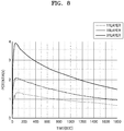
- FIG. 8 is a graph illustrating a change in voltage of the RED battery unit of the iontophoresis device in time, according to an embodiment.
- the RED battery unit was configured as follows.
- a non-woven fabric having a thickness in a range of about 0.2 to about 0.5 mm was used to form a chamber containing an electrolyte.
- a cation exchange membrane and an anion exchange memebrane were available from ASAHI GLASS Co..
- SBX tape (available from CROSS) was used as a spacer, a container, and a support for attaching the non-woven fabric, the cation exchange membrane, and the anion exchange membrane.
- a size of the chamber was 1.5 cm X 1.3 cm, and the RED battery units having 11 layers, 19 layers, and 31 layers were each prepared with the chamber as one layer, and voltage changes in time were measured. The measurement of voltages in time was performed for 40 minutes after supplying and activiating the prepared RED battery unit. Voltages and currents were measured by contacting a copper plate to the RED battery unit by using a current meter, digital multimeter 34410A, available from Keysight.
- the RED battery unit has a tendency to form a particular voltage and to continue to decrease once reaching the peak voltage after being activated. However, despite the continuous decrease, it may be confirmed that the voltage was sufficient enough to deliver the material in the material containing unit to the object. Also, it may be confirmed that the output peak voltage increased as the number of the chambers containing an electrolyte increased, where the chamber containing an electrolyte constituted one layer.
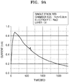
- FIG. 9 is a graph illustrating a change in current of the RED battery unit of the iontophoresis device in time, according to an embodiment.
- the RED battery unit was prepared in the same manner as in preparation of the RED battery unit for the measurement of FIG. 6 , except that the number of chamber layers was 31, a size of the chamber was 1 cm X 0.8 cm, and concentrations of the chambers were changed.
- a concentration in the chamber containing an electrolyte at a high concentration was 1.72 M in FIG. 9A , and 5 M in FIG. 9B .
- a concentration in the chamber containing an electrolyte at a low concentration was 0.011 M.
- the RED battery unit has a tendency to form a particular current and to continue to decrease once reaching the peak current after being activated. However, despite the continuous decrease, it may be confirmed that the current was sufficient enough to deliver the material in the material containing unit to the object. Also, it may be confirmed that a current of greater intensity was formed when a concentration difference of electrolytes increased or a concentration of the chamber containing an electrolyte increased.
- FIG. 10 is a graph illustrating drug delivery effects of the iontophoresis device according to an embodiment.
- the RED battery unit was prepared in the same manner as in preparation of the RED battery unit prepared for the measurement in FIG. 6 , except that the number of chamber layers was 15, and a size of the chamber was 1 cm X 0.8 cm.
- 3M clectrically conductible adhesive tape (ECAT) which is conductive fabric, was used as an intermediate unit.
- the first material containing unit was prepared as follows. 2.5 wt% of 2-phospho I-ascorbic acid trisodium (VCP) (available from Sigma Aldrich, US) and 3 w/v% of Carbopol 940 were dissolved in 1X PBS having pH of 7.4.
- VCP 2-phospho I-ascorbic acid trisodium
- Carbopol 940 were dissolved in 1X PBS having pH of 7.4.
- a pH of the first material containing unit including vitamin C (VCP) was adjusted to 7. This is a stable pH at which VCP exists in the ionized form.
- VCP vitamin C
- a thickening agent used in preparation of a dosage form Carbopol was prepared as a sol while controlling a pH using pH indicator paper (available from GE healthcare, UK). The resultant was sufficiently stirred by using a glass rod so that a material in the first material containing unit was homogenous after each titration process.
- the second material containing unit was prepared in the same manner as in preparation of the first material containing unit, except that 0.9 wt% of NaCl was used instead of 2.5 wt% of VCP, and Carbopol serving as a buffer of a drug negative part was prepared as a sol.
- skin tissue was taken from a haireless mouse (Sk-hr 1, available from Hallym Experimental Animal Center). In particular, after administering euthanasia to the mouse, back skin of a site near the tail was hold by ring-shaped forceps, cut out a small portion by using scissors, and the skin and tissue membrane were disconnected by inserting the scissors inside the skin.
- the skin was washed twice back and forth using 50% MeOH and 50% water for 10 seconds and then washed twice back and forth using 100% MeOH for 10 seconds.
- a stripping tape was attached on an outer surface of the skin, spread with ring-shaped forceps, and repeated three times to separate the stratum corneum of the skin.
- SC stratum corneum
- three stripping tapes were collected in a conical tube, placed in 3 mL of HPLC mobile phase, and remained in a shaker for 3 hours.
- the skin was finely cut with scissors, placed in a 15 ml conical tube, placed in 3 ml of HPLC mobile phase, and ground with a homogenizer.
- the iontophoresis device may deliver more drugs to the subcutaneous blood vessels through the skin.
Landscapes
- Health & Medical Sciences (AREA)
- Engineering & Computer Science (AREA)
- Life Sciences & Earth Sciences (AREA)
- General Health & Medical Sciences (AREA)
- Veterinary Medicine (AREA)
- Public Health (AREA)
- Animal Behavior & Ethology (AREA)
- Biomedical Technology (AREA)
- Nuclear Medicine, Radiotherapy & Molecular Imaging (AREA)
- Radiology & Medical Imaging (AREA)
- Chemical & Material Sciences (AREA)
- Medical Informatics (AREA)
- Anesthesiology (AREA)
- Hematology (AREA)
- Heart & Thoracic Surgery (AREA)
- Dermatology (AREA)
- Bioinformatics & Cheminformatics (AREA)
- Chemical Kinetics & Catalysis (AREA)
- Sustainable Energy (AREA)
- Manufacturing & Machinery (AREA)
- Sustainable Development (AREA)
- Electrochemistry (AREA)
- General Chemical & Material Sciences (AREA)
- Medicinal Chemistry (AREA)
- Electrotherapy Devices (AREA)
- Epidemiology (AREA)
- Organic Chemistry (AREA)
- Molecular Biology (AREA)
- Birds (AREA)
- Polymers & Plastics (AREA)
- Pharmacology & Pharmacy (AREA)
- Genetics & Genomics (AREA)
- Biophysics (AREA)
- Biochemistry (AREA)
- Proteomics, Peptides & Aminoacids (AREA)
- Gastroenterology & Hepatology (AREA)
- Zoology (AREA)
- Toxicology (AREA)
Applications Claiming Priority (2)
| Application Number | Priority Date | Filing Date | Title |
|---|---|---|---|
| PCT/KR2016/000033 WO2017119519A1 (ko) | 2016-01-05 | 2016-01-05 | 약물 전달을 위한 이온토포레시스 장치 및 그를 제조하는 방법 |
| KR1020160000773A KR101772140B1 (ko) | 2016-01-05 | 2016-01-05 | 약물 전달을 위한 이온토포레시스 장치 및 그를 제조하는 방법 |
Publications (2)
| Publication Number | Publication Date |
|---|---|
| EP3400985A1 true EP3400985A1 (de) | 2018-11-14 |
| EP3400985A4 EP3400985A4 (de) | 2019-07-31 |
Family
ID=59274242
Family Applications (1)
| Application Number | Title | Priority Date | Filing Date |
|---|---|---|---|
| EP16883905.8A Withdrawn EP3400985A4 (de) | 2016-01-05 | 2016-01-05 | Iontophoresevorrichtung zur abgabe eines arzneimittels und verfahren zur herstellung davon |
Country Status (7)
| Country | Link |
|---|---|
| US (1) | US11571567B2 (de) |
| EP (1) | EP3400985A4 (de) |
| JP (1) | JP6625756B2 (de) |
| KR (1) | KR101772140B1 (de) |
| CN (1) | CN108883261B (de) |
| SG (1) | SG11201703913YA (de) |
| WO (1) | WO2017119519A1 (de) |
Families Citing this family (12)
| Publication number | Priority date | Publication date | Assignee | Title |
|---|---|---|---|---|
| WO2019132107A1 (ko) * | 2017-12-29 | 2019-07-04 | 한국에너지기술연구원 | 염분차 발전 기반 에너지 자립형 생체신호 실시간 모니터링 및/또는 영양분 전달 시스템 |
| KR102141683B1 (ko) * | 2017-12-29 | 2020-09-14 | 한국에너지기술연구원 | 염분차 발전 기반 에너지 자립형 생체신호 실시간 모니터링 및 영양분 전달 시스템 |
| KR101959524B1 (ko) * | 2018-09-19 | 2019-03-18 | 주식회사 우신라보타치 | 리도카인을 포함한 이온토포레시스용 점착성 카타플라스마 시스템 |
| KR102143459B1 (ko) * | 2018-10-25 | 2020-08-12 | 한국에너지기술연구원 | 생체분해성 전지, 이의 제조방법 및 이의 용도 |
| CN113226278B (zh) | 2019-01-02 | 2023-07-21 | 宝洁公司 | 含有肽化合物和水前寺海苔胞外多糖提取物的皮肤护理组合物 |
| KR102022336B1 (ko) * | 2019-03-12 | 2019-09-18 | 주식회사 우신라보타치 | 국소 통증 완화 카타플라즈마 패치 |
| CN111888641B (zh) * | 2019-05-06 | 2023-09-22 | 上海肤泰科技有限公司 | 离子电渗透的给药装置 |
| DE102020106115A1 (de) | 2020-03-06 | 2021-09-09 | Lts Lohmann Therapie-Systeme Ag | Iontophoretische Zusammensetzung zur Verabreichung von S-Ketamin |
| CN111558134A (zh) * | 2020-05-19 | 2020-08-21 | 成都怀慈福佑电子科技有限公司 | 采用高效环保型生物相容性离子电池的离子电渗疗法装置 |
| US11571378B2 (en) | 2021-01-22 | 2023-02-07 | The Procter & Gamble Company | Skin care composition and method of using the same |
| US11771637B2 (en) | 2021-01-22 | 2023-10-03 | The Procter & Gamble Company | Skin care composition and method of using the same |
| US11339483B1 (en) | 2021-04-05 | 2022-05-24 | Alchemr, Inc. | Water electrolyzers employing anion exchange membranes |
Family Cites Families (63)
| Publication number | Priority date | Publication date | Assignee | Title |
|---|---|---|---|---|
| US4744787A (en) * | 1984-10-29 | 1988-05-17 | Medtronic, Inc. | Iontophoresis apparatus and methods of producing same |
| DE3789898T2 (de) * | 1986-07-10 | 1994-09-08 | Terumo Corp | Referenzelektrode. |
| US5496266A (en) * | 1990-04-30 | 1996-03-05 | Alza Corporation | Device and method of iontophoretic drug delivery |
| GB2265088B (en) * | 1992-03-10 | 1996-02-07 | Kyosti Eero Antero Kontturi | Electrochemical device for drug delivery |
| CA2126487C (en) * | 1993-06-23 | 2001-05-29 | Keiichiro Okabe | Iontophoresis device |
| EP0748636B1 (de) | 1995-06-14 | 2003-08-27 | Hisamitsu Pharmaceutical Co., Inc. | Schnittstelle für Iontophorese |
| JP3905578B2 (ja) * | 1995-06-14 | 2007-04-18 | 久光製薬株式会社 | イオントフォレシス用インターフェイス |
| US5985990A (en) * | 1995-12-29 | 1999-11-16 | 3M Innovative Properties Company | Use of pendant free-radically polymerizable moieties with polar polymers to prepare hydrophilic pressure sensitive adhesive compositions |
| US6650934B2 (en) * | 1996-12-17 | 2003-11-18 | Alza Corp | Polymeric foam reservoirs for an electrotransport delivery device |
| US6119036A (en) * | 1997-03-26 | 2000-09-12 | The Board Of Regents Of The University Of Oklahoma | Iontophoretic transdermal delivery device |
| JP4180244B2 (ja) * | 1999-04-16 | 2008-11-12 | ジョンソン・アンド・ジョンソン・コンシューマー・カンパニーズ・インコーポレイテッド | 内部センサを有する電気的な移動による送出装置系 |
| US6356779B1 (en) * | 1999-06-04 | 2002-03-12 | 3M Innovative Properties Company | Universally functional biomedical electrode |
| US7805201B2 (en) * | 2000-02-17 | 2010-09-28 | Standen Ltd. | Treating a tumor or the like with an electric field |
| US6306419B1 (en) * | 2000-02-23 | 2001-10-23 | Aegis Biosciences, Llc | Medical uses of styrene sulfonate polymers |
| US6629968B1 (en) * | 2000-06-30 | 2003-10-07 | Vyteris, Inc. | Shelf storage stable iontophoresis reservoir-electrode and iontophoretic system incorporating the reservoir-electrode |
| ES2331302T3 (es) * | 2001-05-01 | 2009-12-29 | A.V. Topchiev Institute Of Petrochemical Synthesis | Composiciones de hidrogel. |
| SG106631A1 (en) * | 2001-08-31 | 2004-10-29 | Agency Science Tech & Res | Liquid delivering device |
| EE200400090A (et) * | 2001-10-31 | 2004-10-15 | R&R Ventures Incorporation | Ionoforeesiseade |
| JP4033382B2 (ja) * | 2002-04-08 | 2008-01-16 | 久光製薬株式会社 | インスリン投与装置 |
| US7099713B2 (en) * | 2002-06-28 | 2006-08-29 | Battelle Memorial Institute | Skin conduction and transport systems |
| AU2003276967A1 (en) * | 2002-09-25 | 2004-04-19 | Flock, Stephen, T. | Microsurgical tissue treatment system |
| JP2004202057A (ja) * | 2002-12-26 | 2004-07-22 | Tokuyama Corp | イオン性薬剤封入袋状物 |
| US7507228B2 (en) * | 2003-06-30 | 2009-03-24 | Johnson & Johnson Consumer Companies, Inc. | Device containing a light emitting diode for treatment of barrier membranes |
| US7477938B2 (en) * | 2003-06-30 | 2009-01-13 | Johnson & Johnson Cosumer Companies, Inc. | Device for delivery of active agents to barrier membranes |
| US7486989B2 (en) * | 2003-06-30 | 2009-02-03 | Johnson & Johnson Consumer Companies, Inc. | Device for delivery of oxidizing agents to barrier membranes |
| US7479133B2 (en) * | 2003-06-30 | 2009-01-20 | Johnson & Johnson Consumer Companies, Inc. | Methods of treating acne and rosacea with galvanic generated electricity |
| US20050019663A1 (en) * | 2003-07-23 | 2005-01-27 | Matsushita Electric Industrial Co., Ltd. | Coin-shaped all solid battery |
| JP4617105B2 (ja) | 2003-07-23 | 2011-01-19 | パナソニック株式会社 | コイン型全固体電池 |
| US20090130189A1 (en) * | 2004-03-19 | 2009-05-21 | Pfizer Health Ab | Means for transdermal administration of nicotine |
| JP4728631B2 (ja) | 2004-11-30 | 2011-07-20 | Tti・エルビュー株式会社 | イオントフォレーシス装置 |
| US7590444B2 (en) * | 2004-12-09 | 2009-09-15 | Tti Ellebeau, Inc. | Iontophoresis device |
| JP4731931B2 (ja) * | 2005-02-03 | 2011-07-27 | Tti・エルビュー株式会社 | イオントフォレーシス装置 |
| JP4793806B2 (ja) * | 2005-03-22 | 2011-10-12 | Tti・エルビュー株式会社 | イオントフォレーシス装置 |
| JP2006296511A (ja) * | 2005-04-15 | 2006-11-02 | Transcutaneous Technologies Inc | 外用剤、外用剤の塗布方法、イオントフォレーシス装置及び経皮パッチ |
| JP2009500078A (ja) * | 2005-07-01 | 2009-01-08 | ミクロリン・エルエルシー | イオン交換膜を有する電気化学的ポンプから成る流体送出装置および流体送出方法 |
| IL169807A (en) * | 2005-07-21 | 2015-03-31 | Steadymed Ltd | Device for administering a drug |
| IL175460A (en) * | 2006-05-07 | 2011-05-31 | Doron Aurbach | Drug delivery device |
| US8386030B2 (en) * | 2005-08-08 | 2013-02-26 | Tti Ellebeau, Inc. | Iontophoresis device |
| US8295922B2 (en) * | 2005-08-08 | 2012-10-23 | Tti Ellebeau, Inc. | Iontophoresis device |
| US20090254018A1 (en) | 2005-08-24 | 2009-10-08 | Mizuo Nakayama | Electrode assembly for freezing-type iontophoresis device |
| WO2007041118A1 (en) * | 2005-09-30 | 2007-04-12 | Tti Ellebeau, Inc. | Iontophoretic device and method of delivery of active agents to biological interface |
| AU2006299520A1 (en) * | 2005-09-30 | 2007-04-12 | Tti Ellebeau, Inc. | Iontophoresis device to deliver multiple active agents to biological interfaces |
| WO2007079193A2 (en) * | 2005-12-30 | 2007-07-12 | Tti Ellebeau, Inc. | Iontophoretic systems, devices, and methods of delivery of active agents to biological interface |
| KR101180105B1 (ko) * | 2006-01-26 | 2012-09-05 | 주식회사 엘지생활건강 | 파지가 용이한 이온토포레시스 장치 |
| KR100816554B1 (ko) * | 2006-10-20 | 2008-03-25 | 최상식 | 피부를 통한 약물의 전달을 위한 일회용 이온토포레시스패치 및 이온토포레시스 패치를 이용한 저가조절주입 패치 |
| US8332028B2 (en) * | 2006-11-28 | 2012-12-11 | Polyplus Battery Company | Protected lithium electrodes for electro-transport drug delivery |
| US8231614B2 (en) * | 2007-05-11 | 2012-07-31 | Tyco Healthcare Group Lp | Temperature monitoring return electrode |
| WO2009000262A1 (de) * | 2007-06-25 | 2008-12-31 | Acino Ag | Elektrophoretisches transdermales applikationssystem |
| WO2009006349A2 (en) * | 2007-06-29 | 2009-01-08 | Polyplus Battery Company | Electrotransport devices, methods and drug electrode assemblies |
| JP2009256295A (ja) * | 2008-04-11 | 2009-11-05 | Kosumedei Seiyaku Kk | 化粧用粘着シート |
| JP2011523763A (ja) * | 2008-05-27 | 2011-08-18 | コーニンクレッカ フィリップス エレクトロニクス エヌ ヴィ | マイクロシステムへの電力供給 |
| US20090299267A1 (en) * | 2008-05-28 | 2009-12-03 | Isis Biopolymer Llc | Iontophoretic drug delivery system with procedure window |
| GB0813227D0 (en) * | 2008-07-18 | 2008-08-27 | Fuji Film Mfg Europ B V | Process for preparing membranes |
| US8190252B2 (en) * | 2009-02-12 | 2012-05-29 | Incube Labs, Llc | Iontophoretic system for transdermal delivery of active agents for therapeutic and medicinal purposes |
| US9008765B2 (en) * | 2009-02-12 | 2015-04-14 | Incube Labs, Llc | System and method for biphasic transdermal iontophoretic delivery of therapeutic agents for the control of addictive cravings |
| AU2010280361B2 (en) * | 2009-08-04 | 2015-10-08 | Pollogen Ltd. | Cosmetic skin rejuvination |
| US8903485B2 (en) * | 2009-08-06 | 2014-12-02 | Incube Labs, Llc | Patch and patch assembly for iontophoretic transdermal delivery of active agents for therapeutic and medicinal purposes |
| CN102049195B (zh) * | 2009-10-30 | 2014-03-26 | 中国石油化工股份有限公司 | 一种对含有可交换离子的固体物质进行离子交换的方法 |
| KR101186510B1 (ko) * | 2010-05-19 | 2012-10-08 | 주식회사 케이피엠테크 | 카본시트가 구비된 전기마스크 장치 |
| JP5335857B2 (ja) * | 2011-06-06 | 2013-11-06 | 忍 伊東 | 有効成分の被写体への導入用シート及びその製造方法 |
| US9044611B2 (en) * | 2013-03-15 | 2015-06-02 | The Regents Of The University Of California | Systems and methods for selectively migrating cells using electric fields |
| KR101511990B1 (ko) | 2013-09-24 | 2015-04-14 | 한국에너지기술연구원 | 역전기투석 장치용 이온 교환막 및 이를 포함하는 역전기투석 장치 |
| CN104368084B (zh) * | 2014-10-31 | 2016-11-30 | 厦门微科格瑞生物科技有限公司 | 可佩戴智能药物导入系统 |
-
2016
- 2016-01-05 WO PCT/KR2016/000033 patent/WO2017119519A1/ko not_active Ceased
- 2016-01-05 EP EP16883905.8A patent/EP3400985A4/de not_active Withdrawn
- 2016-01-05 US US15/777,490 patent/US11571567B2/en active Active
- 2016-01-05 CN CN201680077969.6A patent/CN108883261B/zh not_active Expired - Fee Related
- 2016-01-05 KR KR1020160000773A patent/KR101772140B1/ko not_active Expired - Fee Related
- 2016-01-05 SG SG11201703913YA patent/SG11201703913YA/en unknown
- 2016-01-05 JP JP2018536189A patent/JP6625756B2/ja not_active Expired - Fee Related
Also Published As
| Publication number | Publication date |
|---|---|
| WO2017119519A1 (ko) | 2017-07-13 |
| JP2019500978A (ja) | 2019-01-17 |
| CN108883261A (zh) | 2018-11-23 |
| CN108883261B (zh) | 2021-09-28 |
| JP6625756B2 (ja) | 2019-12-25 |
| SG11201703913YA (en) | 2017-08-30 |
| US11571567B2 (en) | 2023-02-07 |
| US20180369579A1 (en) | 2018-12-27 |
| KR20170081838A (ko) | 2017-07-13 |
| KR101772140B1 (ko) | 2017-08-28 |
| EP3400985A4 (de) | 2019-07-31 |
Similar Documents
| Publication | Publication Date | Title |
|---|---|---|
| US11571567B2 (en) | Iontophoresis device for drug delivery and method for manufacturing the same | |
| US10945516B2 (en) | Device mounted on mask pack, mask pack and kit comprising the same | |
| EP0596036B1 (de) | Transdermale abgabevorrichtung | |
| US5464387A (en) | Transdermal delivery device | |
| WO2016056778A1 (ko) | 역전기투석을 이용한 이온토포레시스 장치 및 그를 사용하여 약물을 전달하는 방법 | |
| JP2002501794A (ja) | 電子搬送装置用の電気化学的反応性カソード | |
| JP2003519541A (ja) | 競合イオンを用いた選択的薬剤送達プロフィル | |
| JP2885510B2 (ja) | 電気移送用接着剤 | |
| JP2009509657A (ja) | 生体界面への活性物質の送達のイオントフォレーシス装置及び方法 | |
| KR101698147B1 (ko) | 역전기투석을 이용한 이온토포레시스 장치 및 그를 사용하여 약물을 전달하는 방법 | |
| KR100816554B1 (ko) | 피부를 통한 약물의 전달을 위한 일회용 이온토포레시스패치 및 이온토포레시스 패치를 이용한 저가조절주입 패치 | |
| KR20190005061A (ko) | 미백제를 포함하는 이온토포레시스 약물 전달에 장착되는 장치, 그를 포함하는 이온토포레시스 약물 전달 장치 및 키트 | |
| NZ577718A (en) | Methods of predicting dose of drug and program for predicting dose of drug | |
| Haga et al. | Lidocaine transport through living rat skin using alternating current | |
| US20090216175A1 (en) | Transdermal Administration Device and Method of Controlling the Same | |
| KR20090121268A (ko) | 로펜타닐 및 카펜타닐의 경피적 전기운반 전달 방법 및 장치 | |
| KR20170004683A (ko) | 아모롤핀을 포함하는 이온토포레시스 장치 및 그를 사용하여 아모롤핀을 전달하는 방법 | |
| EP1844813B1 (de) | Iontophoresegerät | |
| KR20170004680A (ko) | 레티놀 및 나이아신아마이드를 포함하는 이온토포레시스 장치 및 그를 사용하여 레티놀 및 나이아신아마이드을 전달하는 방법 | |
| WO2008140453A1 (en) | Iontophoretic devices for drug delivery | |
| KR20170004682A (ko) | 니코틴을 포함하는 이온토포레시스 장치 및 그를 사용하여 니코틴을 전달하는 방법 | |
| CN1938030A (zh) | 哌嗪基-2(3h)-苯并噁唑酮化合物的透皮离子电渗转运 | |
| KR20170004679A (ko) | 비타민 c를 포함하는 이온토포레시스 장치 및 그를 사용하여 비타민 c를 전달하는 방법 | |
| KR20190005062A (ko) | 화상 치료제를 포함하는 이온토포레시스 약물 전달에 장착되는 장치, 그를 포함하는 이온토포레시스 약물 전달 장치 및 키트 | |
| KR20190005064A (ko) | 여드름 치료제를 포함하는 이온토포레시스 약물 전달에 장착되는 장치, 그를 포함하는 이온토포레시스 약물 전달 장치 및 키트 |
Legal Events
| Date | Code | Title | Description |
|---|---|---|---|
| STAA | Information on the status of an ep patent application or granted ep patent |
Free format text: STATUS: THE INTERNATIONAL PUBLICATION HAS BEEN MADE |
|
| PUAI | Public reference made under article 153(3) epc to a published international application that has entered the european phase |
Free format text: ORIGINAL CODE: 0009012 |
|
| STAA | Information on the status of an ep patent application or granted ep patent |
Free format text: STATUS: REQUEST FOR EXAMINATION WAS MADE |
|
| 17P | Request for examination filed |
Effective date: 20180703 |
|
| AK | Designated contracting states |
Kind code of ref document: A1 Designated state(s): AL AT BE BG CH CY CZ DE DK EE ES FI FR GB GR HR HU IE IS IT LI LT LU LV MC MK MT NL NO PL PT RO RS SE SI SK SM TR |
|
| AX | Request for extension of the european patent |
Extension state: BA ME |
|
| DAV | Request for validation of the european patent (deleted) | ||
| DAX | Request for extension of the european patent (deleted) | ||
| A4 | Supplementary search report drawn up and despatched |
Effective date: 20190703 |
|
| RIC1 | Information provided on ipc code assigned before grant |
Ipc: A61N 1/30 20060101ALI20190627BHEP Ipc: A61M 37/00 20060101AFI20190627BHEP |
|
| STAA | Information on the status of an ep patent application or granted ep patent |
Free format text: STATUS: EXAMINATION IS IN PROGRESS |
|
| 17Q | First examination report despatched |
Effective date: 20220714 |
|
| REG | Reference to a national code |
Ref country code: DE Ref legal event code: R079 Free format text: PREVIOUS MAIN CLASS: A61M0037000000 Ipc: A61N0001300000 |
|
| GRAP | Despatch of communication of intention to grant a patent |
Free format text: ORIGINAL CODE: EPIDOSNIGR1 |
|
| STAA | Information on the status of an ep patent application or granted ep patent |
Free format text: STATUS: GRANT OF PATENT IS INTENDED |
|
| RIC1 | Information provided on ipc code assigned before grant |
Ipc: A61N 1/30 20060101AFI20240618BHEP |
|
| INTG | Intention to grant announced |
Effective date: 20240712 |
|
| STAA | Information on the status of an ep patent application or granted ep patent |
Free format text: STATUS: THE APPLICATION IS DEEMED TO BE WITHDRAWN |
|
| 18D | Application deemed to be withdrawn |
Effective date: 20241113 |