EP3400841B1 - Element a raideur reglable pour meuble de couchage ou d'assise - Google Patents
Element a raideur reglable pour meuble de couchage ou d'assise Download PDFInfo
- Publication number
- EP3400841B1 EP3400841B1 EP18171876.8A EP18171876A EP3400841B1 EP 3400841 B1 EP3400841 B1 EP 3400841B1 EP 18171876 A EP18171876 A EP 18171876A EP 3400841 B1 EP3400841 B1 EP 3400841B1
- Authority
- EP
- European Patent Office
- Prior art keywords
- compression
- axis
- flexible element
- flexible
- compression spring
- Prior art date
- Legal status (The legal status is an assumption and is not a legal conclusion. Google has not performed a legal analysis and makes no representation as to the accuracy of the status listed.)
- Active
Links
Images





Classifications
-
- A—HUMAN NECESSITIES
- A47—FURNITURE; DOMESTIC ARTICLES OR APPLIANCES; COFFEE MILLS; SPICE MILLS; SUCTION CLEANERS IN GENERAL
- A47C—CHAIRS; SOFAS; BEDS
- A47C23/00—Spring mattresses with rigid frame or forming part of the bedstead, e.g. box springs; Divan bases; Slatted bed bases
- A47C23/002—Spring mattresses with rigid frame or forming part of the bedstead, e.g. box springs; Divan bases; Slatted bed bases with separate resilient support elements, e.g. elastomeric springs arranged in a two-dimensional matrix pattern
-
- A—HUMAN NECESSITIES
- A47—FURNITURE; DOMESTIC ARTICLES OR APPLIANCES; COFFEE MILLS; SPICE MILLS; SUCTION CLEANERS IN GENERAL
- A47C—CHAIRS; SOFAS; BEDS
- A47C23/00—Spring mattresses with rigid frame or forming part of the bedstead, e.g. box springs; Divan bases; Slatted bed bases
- A47C23/04—Spring mattresses with rigid frame or forming part of the bedstead, e.g. box springs; Divan bases; Slatted bed bases using springs in compression, e.g. coiled
- A47C23/043—Spring mattresses with rigid frame or forming part of the bedstead, e.g. box springs; Divan bases; Slatted bed bases using springs in compression, e.g. coiled using wound springs
- A47C23/0435—Spring mattresses with rigid frame or forming part of the bedstead, e.g. box springs; Divan bases; Slatted bed bases using springs in compression, e.g. coiled using wound springs of adjustable resilience
-
- A—HUMAN NECESSITIES
- A47—FURNITURE; DOMESTIC ARTICLES OR APPLIANCES; COFFEE MILLS; SPICE MILLS; SUCTION CLEANERS IN GENERAL
- A47C—CHAIRS; SOFAS; BEDS
- A47C23/00—Spring mattresses with rigid frame or forming part of the bedstead, e.g. box springs; Divan bases; Slatted bed bases
- A47C23/04—Spring mattresses with rigid frame or forming part of the bedstead, e.g. box springs; Divan bases; Slatted bed bases using springs in compression, e.g. coiled
-
- A—HUMAN NECESSITIES
- A47—FURNITURE; DOMESTIC ARTICLES OR APPLIANCES; COFFEE MILLS; SPICE MILLS; SUCTION CLEANERS IN GENERAL
- A47C—CHAIRS; SOFAS; BEDS
- A47C23/00—Spring mattresses with rigid frame or forming part of the bedstead, e.g. box springs; Divan bases; Slatted bed bases
- A47C23/04—Spring mattresses with rigid frame or forming part of the bedstead, e.g. box springs; Divan bases; Slatted bed bases using springs in compression, e.g. coiled
- A47C23/043—Spring mattresses with rigid frame or forming part of the bedstead, e.g. box springs; Divan bases; Slatted bed bases using springs in compression, e.g. coiled using wound springs
- A47C23/0438—Spring mattresses with rigid frame or forming part of the bedstead, e.g. box springs; Divan bases; Slatted bed bases using springs in compression, e.g. coiled using wound springs of special shape
-
- A—HUMAN NECESSITIES
- A47—FURNITURE; DOMESTIC ARTICLES OR APPLIANCES; COFFEE MILLS; SPICE MILLS; SUCTION CLEANERS IN GENERAL
- A47C—CHAIRS; SOFAS; BEDS
- A47C23/00—Spring mattresses with rigid frame or forming part of the bedstead, e.g. box springs; Divan bases; Slatted bed bases
- A47C23/06—Spring mattresses with rigid frame or forming part of the bedstead, e.g. box springs; Divan bases; Slatted bed bases using wooden springs, e.g. of slat type
- A47C23/062—Slat supports
- A47C23/067—Slat supports adjustable, e.g. in height or elasticity
-
- A—HUMAN NECESSITIES
- A47—FURNITURE; DOMESTIC ARTICLES OR APPLIANCES; COFFEE MILLS; SPICE MILLS; SUCTION CLEANERS IN GENERAL
- A47C—CHAIRS; SOFAS; BEDS
- A47C27/00—Spring, stuffed or fluid mattresses or cushions specially adapted for chairs, beds or sofas
- A47C27/04—Spring, stuffed or fluid mattresses or cushions specially adapted for chairs, beds or sofas with spring inlays
- A47C27/06—Spring inlays or spring units therefor
- A47C27/065—Spring inlays or spring units therefor of special shape
-
- A—HUMAN NECESSITIES
- A47—FURNITURE; DOMESTIC ARTICLES OR APPLIANCES; COFFEE MILLS; SPICE MILLS; SUCTION CLEANERS IN GENERAL
- A47C—CHAIRS; SOFAS; BEDS
- A47C23/00—Spring mattresses with rigid frame or forming part of the bedstead, e.g. box springs; Divan bases; Slatted bed bases
- A47C23/04—Spring mattresses with rigid frame or forming part of the bedstead, e.g. box springs; Divan bases; Slatted bed bases using springs in compression, e.g. coiled
- A47C23/05—Frames therefor; Connecting the springs to the frame ; Interconnection of springs, e.g. in spring units
Definitions
- the present disclosure relates to the field of furniture and more particularly a flexible element with adjustable stiffness for sleeping or seating furniture, an assembly comprising a plurality of such flexible elements with adjustable stiffness and a method for adjusting the stiffness of a flexible element for bed or seat furniture.
- assemblies such as mattresses or box springs, with flexible elements with adjustable stiffness have been previously disclosed, by example in EP 1 386 564 A1 , EP 1,155,643 A2 , WO 2008/015235 , WO 96/27312 , US 4,667,357 , EP2526835 A1 , EP2803297 A1 or DE 10 2008 050 108 A1 .
- the stiffness of the elements is adjusted there with restrictions on their mechanical deformation. For this, however, the proposed mechanisms have significant complexity and / or bulk.
- the present disclosure aims to remedy these drawbacks by proposing a flexible element with adjustable stiffness along a compression axis, for seating or sleeping furniture, with a simple structure and a limited size.
- the flexible element comprising a compression spring
- the flexible element also comprises a mechanism coupled to the compression spring to be actuated, for a movement in a direction different from that of the compression axis, by compression of the compression spring along the compression axis.
- the mechanism can in particular comprise an elastic articulation connected in overhang, in direction orthogonal to the compression axis, to the compression spring, with a torsion axis orthogonal to the compression axis, and an adjustment device for selectively restrict and release a rotation of the elastic joint around the axis of torsion.
- Such a mechanism can be easily integrated into the flexible element without large additional space around the spring.
- the mechanism may also comprise a rod integral with the elastic articulation in rotation about the axis of torsion and in which the adjustment device comprises a stop movable between a first position restricting rotation of the rod around the axis of torsion and a second position releasing the rotation of the rod around the axis of torsion.
- the adjustment device can thus be implemented in a particularly simple manner.
- the adjustment device may comprise a rotary part integral with the stop, the rotary part being able to rotate, between the first position and the second position, around the compression axis.
- the rod can be elastically flexible. Thus, it can stiffen rather than block the elastic joint when the rotation of the rod is restricted in the first position of the stop of the adjustment device. Furthermore, the rod can be curved. Configured in this way, it can in particular at least partially bypass the compression spring, to be arranged therein compactly, without enlarging the imprint of the flexible element in a plane perpendicular to the compression axis and without interfering with compression. of the compression spring.
- the compression spring can in particular be helical.
- such a helical compression spring can be configured as a rod wound in a helix around the axis of compression. The compression along the compression axis can then translate into a torsional stress of this helical rod around the propeller.
- this torsional stress can in particular contribute to the rotation of the elastic joint and of the rod integral with the latter around the axis of torsion.
- the flexible element may in particular comprise a plurality of coaxial compression springs.
- this plurality of coaxial compression springs can comprise several identical coaxial compression springs with a regular angular offset between them. It is thus possible to increase the lateral stability of the flexible element and reduce the risk of buckling under compression.
- the flexible element may comprise a plurality of mechanisms, each of which is coupled to a respective compression spring among the plurality of compression springs to be actuated, for movement in a direction different from that of the compression axis, by compression, along the compression axis, of the respective compression spring, the adjustment device being capable of selectively restricting and releasing the movement of the plurality of mechanisms simultaneously.
- each mechanism can comprise an elastic articulation, connected in overhang, in direction orthogonal to the compression axis, to the respective compression spring, with a respective torsion axis orthogonal to the compression axis.
- the adjustment device can then be able to selectively restrict and release a rotation of each elastic articulation of the plurality of mechanisms relative to the respective axis of torsion.
- each mechanism of the plurality of mechanisms may comprise a rod integral, in rotation about a respective axis of torsion, with the respective elastic joint.
- the adjustment device can then include a plurality of stops movable between a first position restricting rotation of the rods of the plurality of mechanisms around the respective torsion axes and a second position releasing rotation of the rods around the respective torsion axes.
- the adjustment device can act simultaneously on the stiffness of several compression springs.
- two rods of the plurality of mechanisms can be connected by a joint.
- This articulation can in particular comprise a flexible sleeve receiving respective ends of the two rods.
- the flexible sleeve can in particular be split in order to facilitate its bending.
- the plurality of compression springs may in particular comprise compression springs arranged mechanically in parallel and / or in series. It can also be molded at least partially by injection. Injection molding can in particular make it possible to facilitate the production of flexible elements at least partially made of organic polymer material, in particular thermoplastic. However, other materials, for example metallic, as well as other production methods, such as for example additive manufacturing, can be used alternatively or in addition to organic polymer materials and molding or extrusion, respectively.
- Another aspect of the present disclosure relates to a seat, back or sleeping arrangement comprising a plurality of such flexible elements.
- This set can in particular be a box spring or a mattress.
- the adjacent flexible element adjustment devices among the plurality of flexible elements can be mechanically coupled for common actuation.
- the assembly may include pivots mechanically coupling the adjuster devices of adjacent flexible elements among the plurality of flexible elements for common actuation.
- Yet another aspect of the present disclosure relates to a method of adjusting stiffness, along a compression axis, of a flexible element.
- This flexible element comprises a compression spring aligned with the compression axis and a mechanism coupled to the compression spring to be actuated, for a movement in a direction different from that of the compression axis, by compression of the compression spring. compression along the compression axis.
- the stiffness adjustment method comprises a step in which an adjustment device selectively restricts or releases the movement of the mechanism.
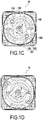
- a flexible element 10, intended for seat or bed furniture, and whose stiffness along a compression axis Z is adjustable is illustrated on the Figures 1A to 1D .
- this flexible element 10 can comprise several elastic parts arranged in series along the compression axis Z.
- it can comprise a first elastic part 20 and a second elastic part 30 mechanically arranged in series along the compression axis Z and connected to each other by a connection 40 which can be located, as in the example illustrated, in the center of the flexible element 10.
- Each of the two elastic parts 20, 30 can comprise at least two compression springs 50 mechanically arranged in parallel as in the example illustrated.
- these compression springs 50 can be, as in the example illustrated on the figure 1A , helical springs formed by rods wound in a helix H around the compression axis Z.
- the angular offset around the compression axis Z between the helices of the springs 50 helical and coaxial compression can be regular.
- the angular offset between the compression springs 50 of each elastic piece 20, 30 can be 360 ° / x, where x is the number of compression springs 50 in parallel in each elastic piece 20, 30.
- the angular offset can be 180 °.
- each elastic piece 20, 30 may further comprise a connector 60, 70 complementary, respectively, to the connector 70, 60 of the other elastic piece 30, 20 to form the connection 40, as well as a support platform 80, 90.
- the connectors 60, 70 and the support platforms 80, 90 can be arranged on opposite ends of the respective elastic parts 20, 30.
- this flexible element 10 can extend from one to the other of the support platforms 80, 90, along the compression axis Z.
- each compression spring 50 can be connected directly to the respective connector 60, 70, while the other end can be connected to the support platform 80, 90 to through an elastic joint 100.
- Each of these elastic joints 100 may in particular have a torsion axis Y substantially orthogonal to the compression axis Z and be connected to the respective compression spring 50 by a more rigid arm 110, oriented in a radial direction substantially orthogonal to the compression axis Z and to the respective axis of torsion Y, so that the elastic joint 100 is cantilevered with the compression spring 50 in the direction orthogonal to the axis of compression Z.
- each elastic articulation 100 can take the form of a torsion rod connecting the arm 110 to the support platform 80, 90.
- other forms are also conceivable.
- each elastic piece 20, 30 of the illustrated example may also include other rods 120 secured to the arms 110. More specifically, each rod 120 may extend from a first end 121 secured to a respective arm 110 at a second end 122. Each second end 122 can be offset with respect to the axis of torsion Y of the elastic joint 100 corresponding to the respective arm 110 in a plane orthogonal to this axis of torsion Y, so as to rotate around the torsion axis Y with the respective arm 110.
- each rod 120 can be curved, and in particular follow a helix wider than those of the compression springs 50, so as to bypass them so that the first and second ends 121, 122 of each rod 120 are located on diametrically opposite sides of the springs 50, while also being mutually offset in a direction parallel to the compression axis Z.
- the rods 120 are also elastically flexible.
- each elastic articulation 100 forms, with the corresponding arm 110 and rod 120, a mechanism 150 configured so that the compression of the respective compression spring 50 in the compression axis Z actuates a movement of the second end of the rod 120 in radial direction with respect to the compression axis Z, as illustrated on the figure 2B .
- each rod 120 of one of the elastic parts 20, 30 can be connected by an articulation to the second end 122 of a rod 120 opposite to the other of the elastic parts 30 , 20. More specifically, the corresponding second ends 122 of each pair of opposite rods 120 can be received in opposite ends 131, 132 of a flexible sleeve 130 which can thus form such a joint.
- the flexible sleeves 130 can in particular be split perpendicular to their main axis, so as to increase their flexibility.
- the flexible element 10 can also comprise a device for adjusting the stiffness of the flexible element 10 in the compression axis Z.
- This adjustment device can in particular be configured as a rotary part 140, as illustrated on Figures 1A to 1C .
- This rotary part 140 can be retained by the connectors 60, 70 so as to be rotatable around the compression axis Z.
- the rotary part 140 may comprise several openings 141 traversed by the flexible sleeves 130 in the direction parallel to the compression axis Z. Each opening 141 may extend over a respective arc around the compression axis Z.
- each opening 141 may include a first section 142 and a second section 143, the first section 142 possibly being narrower than the second section 143 in the radial direction relative to the compression axis Z. More specifically, the outer edge of each opening 141 may be closer to the compression axis Z in the first section 142 than in the second section 143, and thus form a radial stop 145 to restrict radial movement of the flexible sleeve 130 respectively, and therefore also second ends 122 of rods 120 fitted into this flexible sleeve 130, relative to the compression axis Z.
- the rotary part 140 can thus t rotate between a first position, in which the flexible sleeves 130 are received in the first sections 142 of the openings 141 and the stops 145 restrict the radial spacing of the flexible sleeves 130, and therefore of the second ends 122 of the rods 120 relative to the compression axis Z, as illustrated on Figures 1A to 1C , and a second position in which the flexible sleeves 130 will be received in the second, wider sections 143, of the openings 141, thus freeing the flexible sleeves 130 is the second ends 122 of the rods 120, as illustrated in the figure 1D , to allow them greater spacing radial with respect to the compression axis Z, such as that illustrated on the figure 2B .
- the elastic parts 20, 30, the rotary part 140 and the flexible sleeves 130 can be made of organic polymer material, in particular thermoplastic such as, for example a polyamide, a polyoxymethylene, or a copolyester. However, other materials, for example metallic, can be used alternatively or in combination with such polymeric materials.
- the elastic parts 20, 30 and the rotary part 140 can in particular be molded, in particular by injection.
- the flexible sleeves 130 can in particular be cut from an extruded part.
- other production methods such as, for example, additive manufacturing, can be used alternatively or in addition to molding or extrusion.
- the operation of the flexible element 10 of the illustrated example can also be described with reference to Figures 1A to 2B .
- the rotary part 140 forming a stiffness adjustment device is in its second position, with the flexible sleeves 130 received in the second, larger sections 143, of the openings 141, and the flexible element 10 is subjected to a force of compression F along the compression axis Z, between the support platforms 80, 90, the compression springs 50 will be compressed and the arms 110 connecting them to the elastic joints 100 rotate around the torsion axis Y, with the rods 120.
- the second ends 122 of the rods 120 can deviate radially from the compression axis Z, without opposition to the width of the second sections 143 of the openings 141 of the rotating part 140, as illustrated in the figure 2B .
- the flexible element 10 thus remains relatively flexible in compression.
- the stops 145 can restrict the radial spacing, relative to the compression axis Z, of the flexible sleeves 130 and therefore of the second ends 122 of the rods 120, thus restricting the rotation of the rods 120 around the axes of torsion Y of the respective elastic joints 100 when the flexible element 10 is subjected to compression F along the compression axis Z.
- the flexible elements 10 can have a stiffness in the compression axis Z which is substantially greater when the rotary part 140 is in its first position than when the rotary part 140 is in its second position.
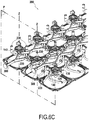
- FIGS. 3A, 3B , 4A, 4B , 5A and 5B illustrate the core of a mattress 200 on a bed 300.
- the core of this mattress 200 may comprise a plurality of flexible elements 10, arranged as in the example illustrated in several rows and columns in a plane perpendicular to the axes of compression Z.
- the support platforms 80, 90 of adjacent flexible elements 10 can be connected by flexible connections 210.
- each of the rotary parts 140 may for example comprise at least one flexible blade 220, arranged on the periphery of the rotary part 140, oriented in a plane perpendicular to the compression axis Z, and bent radially outward relative to the compression axis Z.
- Flexible blades 220 of rotating parts 140 of adjacent flexible elements 10 can be connected by pivots 230 with axes of pivoting parallel to the compression axes Z of the flexible elements 10.
- the distance between each pivot 230 and the compression axes Z of each of the two adjacent flexible elements 10 of which this pivot 230 connects the rotating parts 140 may be greater than half the distance between the compression axes Z of the two adjacent flexible elements 10, so that, when the rotating parts 140 of the adjacent flexible elements 10 are in their respective first positions, as illustrated in the figure 3C , the pivot 230 is on one side of a flat plane P connecting the compression axes Z of the two adjacent flexible elements 10, when the rotary parts 140 of the adjacent flexible elements 10 are in their respective second positions, as illustrated in the figure 4C , the pivot 230 is on the other side of the plane P and that, to move the rotating parts 140 of the flexible elements 10 adjacent from their first positions to their respective second positions, the pivot 230 must pass through an intermediate position, in the plane P , in which the flexible blades 220 are elastically constrained
- the elasticity of the flexible blades 220 makes it possible to provide return forces towards, respectively, the first and second positions of the rotating parts 140 of the flexible elements 10 adjacent to each side of the intermediate position, to maintain these first and second positions of stably and avoid the involuntary passage from one to the other, and therefore an involuntary change in the stiffness of the flexible elements 10.
- the user can make a conscious effort, against the elasticity of the flexible blades 220, to pass through the intermediate position in order to moving the rotating parts 140 between their first and second positions.
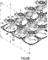
- FIG. 6A to 6C An alternative embodiment is illustrated on the Figures 6A to 6C .
- the flexible elements 10 are similar to those of the first example, and similar components are therefore given the same reference numbers in the drawings.
- the rotating parts 140 in this second example can be simpler than those in the first example, and simply comprise radial arms 146 carrying the radial stops 145 at their respective ends but, as in the first example, each rotary part 140 can rotate between a first position in which these radial stops 145 restrict the radial spacing of the flexible sleeves 130, and therefore also of the second ends 122 rods 120 fitted into these flexible sleeves 130, relative to the compression axis Z, and a second position in which the rotary part 140 no longer restricts this movement of radial spacing.
- the pivots 230 may not connect the rotating parts 140 directly to adjacent rotating parts 140, but rather to control members 300, which can be arranged between the rows of flexible elements 10 and moved in a straight line between the first and second position.
- the flexible blades 220 can moreover, in this alternative example, be integrated into the control members 300, such that these control members 300 pass through an intermediate position, between the first and second position, in which the flexible blades 220 are constrained elastically, against their respective camber.
- the flexible elements 10 can have a bending elasticity perpendicular to their compression axes Z, so as to allow an elastic lateral movement of the rotating parts 140 in their intermediate positions between the first and second positions.
- the elasticity of the flexible elements 10 perpendicular to their compression axes Z could provide the return forces towards the first and second positions on each side of the intermediate position.
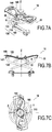
- FIGS 7A to 9C illustrate yet another example of flexible element 10, intended for box springs rather than mattresses.
- the flexible element 10 is similar to those of the first two examples, and the similar components are therefore given the same reference numbers in the drawings.
- This alternative flexible element 10 can comprise a single elastic part 20 and a rotary part 140.
- the elastic part 20 can comprise at least two compression springs 50 mechanically arranged in parallel as in the example illustrated.
- these compression springs 50 may be partially helical springs formed by rods wound in part following a helix H around the compression axis Z.
- the compression springs 50 may comprise bent segments 51 diverging from the helix H so as to minimize their bulk while limiting the risk of interference with other parts of the flexible element 10.
- the rotary part 140 can be similar to those of the second example and include radial arms 146 carrying receptacles 147 at their respective ends. These receptacles 147 can be configured to receive, in the first position of the rotary part 140, the second ends 122 of the rods 120, restricting their radial spacing relative to the compression axis Z when the compression springs 50 are compressed along the compression axis Z, as illustrated on Figures 9A to 9C . As in the previous examples, the rotary part 140 can however rotate between this first position and a second position in which the rotary part 140 no longer restricts this radial spacing movement.
Landscapes
- Mattresses And Other Support Structures For Chairs And Beds (AREA)
Priority Applications (1)
| Application Number | Priority Date | Filing Date | Title |
|---|---|---|---|
| PL18171876T PL3400841T3 (pl) | 2017-05-12 | 2018-05-11 | Element o regulowanej sztywności do mebli do spania lub siedzenia |
Applications Claiming Priority (1)
| Application Number | Priority Date | Filing Date | Title |
|---|---|---|---|
| FR1754172A FR3066087B1 (fr) | 2017-05-12 | 2017-05-12 | Element a raideur reglable pour meuble de couchage ou d'assise |
Publications (2)
| Publication Number | Publication Date |
|---|---|
| EP3400841A1 EP3400841A1 (fr) | 2018-11-14 |
| EP3400841B1 true EP3400841B1 (fr) | 2020-06-03 |
Family
ID=60182624
Family Applications (1)
| Application Number | Title | Priority Date | Filing Date |
|---|---|---|---|
| EP18171876.8A Active EP3400841B1 (fr) | 2017-05-12 | 2018-05-11 | Element a raideur reglable pour meuble de couchage ou d'assise |
Country Status (5)
| Country | Link |
|---|---|
| US (1) | US10722042B2 (pl) |
| EP (1) | EP3400841B1 (pl) |
| ES (1) | ES2812348T3 (pl) |
| FR (1) | FR3066087B1 (pl) |
| PL (1) | PL3400841T3 (pl) |
Families Citing this family (8)
| Publication number | Priority date | Publication date | Assignee | Title |
|---|---|---|---|---|
| FR3066087B1 (fr) | 2017-05-12 | 2019-07-05 | Tournadre Sa Standard Gum | Element a raideur reglable pour meuble de couchage ou d'assise |
| FR3066088B1 (fr) * | 2017-05-12 | 2019-07-05 | Tournadre Sa Standard Gum | Dispositif de reglage de raideur |
| US12193573B2 (en) * | 2017-08-23 | 2025-01-14 | Dreamwell, Ltd. | Mattress foundation and process of manufacture |
| FR3075908B1 (fr) * | 2017-12-27 | 2020-09-25 | Airbus Operations Sas | Systeme d'amortissement comportant un dispositif amortisseur primaire et un dispositif amortisseur secondaire de raideurs differentes, structure et aeronef associes |
| FR3090307B1 (fr) | 2018-12-21 | 2021-03-12 | Tournadre Sa Standard Gum | Elément souple à raideur réglable pour meuble de couchage et/ou d’assise |
| FR3090305B1 (fr) * | 2018-12-21 | 2021-03-12 | Tournadre Sa Standard Gum | Elément souple à hauteur réglable |
| FR3090306B1 (fr) * | 2018-12-21 | 2021-03-12 | Tournadre Sa Standard Gum | Elément souple à raideur réglable pour meuble de couchage et/ou d’assise |
| CN112674536B (zh) * | 2019-10-17 | 2024-08-02 | 厦门新技术集成有限公司 | 用于家具的弹性模块和弹性垫 |
Family Cites Families (24)
| Publication number | Priority date | Publication date | Assignee | Title |
|---|---|---|---|---|
| US2323286A (en) | 1941-07-23 | 1943-06-29 | Ralph E Ward | Mold for helical springs |
| US2842784A (en) | 1955-12-13 | 1958-07-15 | Grund John | Adjustable mattress springs |
| US3084926A (en) | 1957-07-10 | 1963-04-09 | Jerome H Lemelson | Compression springs |
| US2985895A (en) | 1958-04-24 | 1961-05-30 | Bloom Abraham | Adjustable box springs |
| US3608107A (en) * | 1969-09-24 | 1971-09-28 | Boris Kentor | Mattress spring with adjustable firmness |
| JPS54126163A (en) * | 1978-03-20 | 1979-10-01 | Nippon Betsudo Seizou Kk | Internallpressureeadjusted bed |
| US4667357A (en) * | 1986-10-08 | 1987-05-26 | Fortune Richard L | Sleep unit having adjustable firmness |
| ES2124118B1 (es) | 1995-03-08 | 1999-08-16 | Martinez Rafael Martinez | Mejoras en dispositivos de muelles aplicables a colchones, asientos y similares. |
| DE29915339U1 (de) * | 1999-09-01 | 2000-01-05 | Hartmann, Siegbert, 32584 Löhne | Federkörper |
| DE10024530A1 (de) | 2000-05-18 | 2001-11-22 | Heidinger Florian | Stützvorrichtung |
| DE20300248U1 (de) | 2002-07-31 | 2003-09-11 | Froli Kunststoffwerk Heinrich | Federelement für Betten |
| US6684435B1 (en) * | 2002-10-24 | 2004-02-03 | L&P Property Management Company | Method of manufacturing bedding or seating product having coaxial coil springs |
| DE20318252U1 (de) * | 2003-11-24 | 2004-12-30 | Froli Kunststoffwerk Heinrich Fromme Ohg | Polsterung für Sitze und Rückenlehnen |
| DE202005006399U1 (de) | 2005-04-21 | 2006-08-24 | Diemer & Dr. Jaspert GbR, (vertretungsberechtigter Gesellschafter: Herr Dr. Bodo F. Jaspert, 85630 Grasbrunn) | Federsystem |
| DE202006012078U1 (de) * | 2006-08-04 | 2007-09-27 | Froli Kunststoffwerk Heinrich Fromme Ohg | Lagerelement für eine Polsterauflage von Sitz- und Liegeflächen |
| US7636971B2 (en) * | 2008-01-18 | 2009-12-29 | Sealy Technology Llc | Innerspring dampening inserts |
| US7805790B2 (en) * | 2008-01-18 | 2010-10-05 | Sealy Technology Llc | Foam springs and innerspring combinations for mattresses |
| US20080209644A1 (en) * | 2008-04-11 | 2008-09-04 | Rainer Wieland | Mattress with a Membrane Spring Array |
| DE102008050108A1 (de) | 2008-10-06 | 2010-04-08 | Schwenk, Hans Ulrich, Dipl.-Ing. | Härteverstellbares Federelement |
| FR2975574B1 (fr) * | 2011-05-23 | 2014-06-13 | Tournadre Sa Standard Gum | Dispositif de suspension pour un sommier a raideur reglable |
| FR3005400B1 (fr) | 2013-05-13 | 2015-11-20 | Tournadre Sa Standard Gum | Dispositif de support pour sommier ou assise |
| ES2899723T3 (es) * | 2015-04-29 | 2022-03-14 | Bekina Nv | Dispositivo de suspensión de listones ajustable |
| FR3066088B1 (fr) * | 2017-05-12 | 2019-07-05 | Tournadre Sa Standard Gum | Dispositif de reglage de raideur |
| FR3066087B1 (fr) | 2017-05-12 | 2019-07-05 | Tournadre Sa Standard Gum | Element a raideur reglable pour meuble de couchage ou d'assise |
-
2017
- 2017-05-12 FR FR1754172A patent/FR3066087B1/fr active Active
-
2018
- 2018-05-11 EP EP18171876.8A patent/EP3400841B1/fr active Active
- 2018-05-11 PL PL18171876T patent/PL3400841T3/pl unknown
- 2018-05-11 ES ES18171876T patent/ES2812348T3/es active Active
- 2018-05-14 US US15/978,353 patent/US10722042B2/en active Active
Non-Patent Citations (1)
| Title |
|---|
| None * |
Also Published As
| Publication number | Publication date |
|---|---|
| US20180325273A1 (en) | 2018-11-15 |
| PL3400841T3 (pl) | 2021-01-25 |
| FR3066087B1 (fr) | 2019-07-05 |
| EP3400841A1 (fr) | 2018-11-14 |
| FR3066087A1 (fr) | 2018-11-16 |
| ES2812348T3 (es) | 2021-03-16 |
| US10722042B2 (en) | 2020-07-28 |
Similar Documents
| Publication | Publication Date | Title |
|---|---|---|
| EP3400841B1 (fr) | Element a raideur reglable pour meuble de couchage ou d'assise | |
| EP3400842B1 (fr) | Dispositif de reglage de raideur | |
| EP2152124B1 (fr) | Organe elastique de suspension en matiere plastique de type ressort, rotule ou similaire pour sommier, matelas ou siege | |
| EP2253502B1 (fr) | Siège auto pour enfant | |
| FR2892983A1 (fr) | Armature de reglage de l'inclinaison du dossier d'un siege de vehicule automobile | |
| FR2841837A1 (fr) | Appareil d'inclinaison de siege pour vehicule automobile | |
| WO1998044379A1 (fr) | Charniere extensible extra-plate | |
| EP2666389B1 (fr) | Dispositif de suspension pour un sommier à raideur réglable | |
| FR2730960A1 (fr) | Dispositif d'inclinaison de dossier de siege, notamment de vehicule | |
| WO1999015802A1 (fr) | Moyen d'articulation entre deux pieces de liaison et suspension de roue de vehicule automobile equipe d'un tel moyen | |
| EP2526835B1 (fr) | Dispositif de suspension pour un sommier à raideur réglable | |
| EP3669706B1 (fr) | Element souple a hauteur reglable | |
| FR2855469A1 (fr) | Dispositif inclinable a deux elements pour siege de vehicule, comprenant une tige de liaison ayant une extremite en l | |
| FR3090307A1 (fr) | Elément souple à raideur réglable pour meuble de couchage et/ou d’assise | |
| EP3669705B1 (fr) | Element souple a raideur reglable pour meuble de couchage et/ou d'assise | |
| FR2884883A1 (fr) | Nouvel organe ressort pour carcasse de suspension d'un siege sommier, matelas ou autre | |
| EP3087872B1 (fr) | Dispositif monobloc de suspension de matelas | |
| FR3047321A1 (fr) | Miroir deformable | |
| FR2671033A1 (fr) | Dispositif automatique de commande d'un correcteur hydraulique de hauteur d'une suspension de train arriere de vehicule automobile, et suspension mixte equipee d'un tel dispositif. | |
| FR2941180A1 (fr) | Dispositif de liaison pour mecanismes de reglage angulaire d'un siege de vehicule et siege comprenant le dispositif de liaison. | |
| FR2495066A1 (fr) | Dispositif d'articulation de pare-soleil | |
| EP3707999B1 (fr) | Barriere de type cornadis | |
| FR2917676A1 (fr) | Mecanisme de reglage a vis, glissiere comportant un tel mecanisme de reglage et siege comportant une telle glissiere | |
| EP0068960A1 (fr) | Assemblage d'articulations pour sièges de véhicule | |
| EP0545831B1 (fr) | Bascule réglable, notamment pour jouets |
Legal Events
| Date | Code | Title | Description |
|---|---|---|---|
| PUAI | Public reference made under article 153(3) epc to a published international application that has entered the european phase |
Free format text: ORIGINAL CODE: 0009012 |
|
| STAA | Information on the status of an ep patent application or granted ep patent |
Free format text: STATUS: THE APPLICATION HAS BEEN PUBLISHED |
|
| AK | Designated contracting states |
Kind code of ref document: A1 Designated state(s): AL AT BE BG CH CY CZ DE DK EE ES FI FR GB GR HR HU IE IS IT LI LT LU LV MC MK MT NL NO PL PT RO RS SE SI SK SM TR |
|
| AX | Request for extension of the european patent |
Extension state: BA ME |
|
| STAA | Information on the status of an ep patent application or granted ep patent |
Free format text: STATUS: REQUEST FOR EXAMINATION WAS MADE |
|
| 17P | Request for examination filed |
Effective date: 20190514 |
|
| RBV | Designated contracting states (corrected) |
Designated state(s): AL AT BE BG CH CY CZ DE DK EE ES FI FR GB GR HR HU IE IS IT LI LT LU LV MC MK MT NL NO PL PT RO RS SE SI SK SM TR |
|
| RIC1 | Information provided on ipc code assigned before grant |
Ipc: A47C 23/04 20060101ALI20191030BHEP Ipc: A47C 27/06 20060101ALI20191030BHEP Ipc: A47C 23/06 20060101ALI20191030BHEP Ipc: A47C 23/00 20060101AFI20191030BHEP |
|
| GRAP | Despatch of communication of intention to grant a patent |
Free format text: ORIGINAL CODE: EPIDOSNIGR1 |
|
| STAA | Information on the status of an ep patent application or granted ep patent |
Free format text: STATUS: GRANT OF PATENT IS INTENDED |
|
| INTG | Intention to grant announced |
Effective date: 20191212 |
|
| RIN1 | Information on inventor provided before grant (corrected) |
Inventor name: CAILLEY, GERAUD Inventor name: LOBRY, PASCAL Inventor name: LOBRY, JACQUES |
|
| INTG | Intention to grant announced |
Effective date: 20191218 |
|
| GRAS | Grant fee paid |
Free format text: ORIGINAL CODE: EPIDOSNIGR3 |
|
| GRAA | (expected) grant |
Free format text: ORIGINAL CODE: 0009210 |
|
| STAA | Information on the status of an ep patent application or granted ep patent |
Free format text: STATUS: THE PATENT HAS BEEN GRANTED |
|
| AK | Designated contracting states |
Kind code of ref document: B1 Designated state(s): AL AT BE BG CH CY CZ DE DK EE ES FI FR GB GR HR HU IE IS IT LI LT LU LV MC MK MT NL NO PL PT RO RS SE SI SK SM TR |
|
| REG | Reference to a national code |
Ref country code: GB Ref legal event code: FG4D Free format text: NOT ENGLISH |
|
| REG | Reference to a national code |
Ref country code: CH Ref legal event code: EP Ref country code: AT Ref legal event code: REF Ref document number: 1276095 Country of ref document: AT Kind code of ref document: T Effective date: 20200615 |
|
| REG | Reference to a national code |
Ref country code: DE Ref legal event code: R096 Ref document number: 602018005000 Country of ref document: DE |
|
| REG | Reference to a national code |
Ref country code: CH Ref legal event code: NV Representative=s name: MICHELI AND CIE SA, CH |
|
| REG | Reference to a national code |
Ref country code: NL Ref legal event code: FP |
|
| REG | Reference to a national code |
Ref country code: SE Ref legal event code: TRGR |
|
| REG | Reference to a national code |
Ref country code: LT Ref legal event code: MG4D |
|
| PG25 | Lapsed in a contracting state [announced via postgrant information from national office to epo] |
Ref country code: GR Free format text: LAPSE BECAUSE OF FAILURE TO SUBMIT A TRANSLATION OF THE DESCRIPTION OR TO PAY THE FEE WITHIN THE PRESCRIBED TIME-LIMIT Effective date: 20200904 Ref country code: FI Free format text: LAPSE BECAUSE OF FAILURE TO SUBMIT A TRANSLATION OF THE DESCRIPTION OR TO PAY THE FEE WITHIN THE PRESCRIBED TIME-LIMIT Effective date: 20200603 Ref country code: NO Free format text: LAPSE BECAUSE OF FAILURE TO SUBMIT A TRANSLATION OF THE DESCRIPTION OR TO PAY THE FEE WITHIN THE PRESCRIBED TIME-LIMIT Effective date: 20200903 Ref country code: LT Free format text: LAPSE BECAUSE OF FAILURE TO SUBMIT A TRANSLATION OF THE DESCRIPTION OR TO PAY THE FEE WITHIN THE PRESCRIBED TIME-LIMIT Effective date: 20200603 |
|
| PG25 | Lapsed in a contracting state [announced via postgrant information from national office to epo] |
Ref country code: RS Free format text: LAPSE BECAUSE OF FAILURE TO SUBMIT A TRANSLATION OF THE DESCRIPTION OR TO PAY THE FEE WITHIN THE PRESCRIBED TIME-LIMIT Effective date: 20200603 Ref country code: HR Free format text: LAPSE BECAUSE OF FAILURE TO SUBMIT A TRANSLATION OF THE DESCRIPTION OR TO PAY THE FEE WITHIN THE PRESCRIBED TIME-LIMIT Effective date: 20200603 Ref country code: LV Free format text: LAPSE BECAUSE OF FAILURE TO SUBMIT A TRANSLATION OF THE DESCRIPTION OR TO PAY THE FEE WITHIN THE PRESCRIBED TIME-LIMIT Effective date: 20200603 Ref country code: BG Free format text: LAPSE BECAUSE OF FAILURE TO SUBMIT A TRANSLATION OF THE DESCRIPTION OR TO PAY THE FEE WITHIN THE PRESCRIBED TIME-LIMIT Effective date: 20200903 |
|
| PG25 | Lapsed in a contracting state [announced via postgrant information from national office to epo] |
Ref country code: AL Free format text: LAPSE BECAUSE OF FAILURE TO SUBMIT A TRANSLATION OF THE DESCRIPTION OR TO PAY THE FEE WITHIN THE PRESCRIBED TIME-LIMIT Effective date: 20200603 |
|
| PG25 | Lapsed in a contracting state [announced via postgrant information from national office to epo] |
Ref country code: PT Free format text: LAPSE BECAUSE OF FAILURE TO SUBMIT A TRANSLATION OF THE DESCRIPTION OR TO PAY THE FEE WITHIN THE PRESCRIBED TIME-LIMIT Effective date: 20201006 Ref country code: EE Free format text: LAPSE BECAUSE OF FAILURE TO SUBMIT A TRANSLATION OF THE DESCRIPTION OR TO PAY THE FEE WITHIN THE PRESCRIBED TIME-LIMIT Effective date: 20200603 Ref country code: SM Free format text: LAPSE BECAUSE OF FAILURE TO SUBMIT A TRANSLATION OF THE DESCRIPTION OR TO PAY THE FEE WITHIN THE PRESCRIBED TIME-LIMIT Effective date: 20200603 Ref country code: CZ Free format text: LAPSE BECAUSE OF FAILURE TO SUBMIT A TRANSLATION OF THE DESCRIPTION OR TO PAY THE FEE WITHIN THE PRESCRIBED TIME-LIMIT Effective date: 20200603 Ref country code: RO Free format text: LAPSE BECAUSE OF FAILURE TO SUBMIT A TRANSLATION OF THE DESCRIPTION OR TO PAY THE FEE WITHIN THE PRESCRIBED TIME-LIMIT Effective date: 20200603 |
|
| PG25 | Lapsed in a contracting state [announced via postgrant information from national office to epo] |
Ref country code: SK Free format text: LAPSE BECAUSE OF FAILURE TO SUBMIT A TRANSLATION OF THE DESCRIPTION OR TO PAY THE FEE WITHIN THE PRESCRIBED TIME-LIMIT Effective date: 20200603 Ref country code: IS Free format text: LAPSE BECAUSE OF FAILURE TO SUBMIT A TRANSLATION OF THE DESCRIPTION OR TO PAY THE FEE WITHIN THE PRESCRIBED TIME-LIMIT Effective date: 20201003 |
|
| REG | Reference to a national code |
Ref country code: DE Ref legal event code: R097 Ref document number: 602018005000 Country of ref document: DE |
|
| REG | Reference to a national code |
Ref country code: ES Ref legal event code: FG2A Ref document number: 2812348 Country of ref document: ES Kind code of ref document: T3 Effective date: 20210316 |
|
| PLBE | No opposition filed within time limit |
Free format text: ORIGINAL CODE: 0009261 |
|
| STAA | Information on the status of an ep patent application or granted ep patent |
Free format text: STATUS: NO OPPOSITION FILED WITHIN TIME LIMIT |
|
| PG25 | Lapsed in a contracting state [announced via postgrant information from national office to epo] |
Ref country code: DK Free format text: LAPSE BECAUSE OF FAILURE TO SUBMIT A TRANSLATION OF THE DESCRIPTION OR TO PAY THE FEE WITHIN THE PRESCRIBED TIME-LIMIT Effective date: 20200603 |
|
| 26N | No opposition filed |
Effective date: 20210304 |
|
| PG25 | Lapsed in a contracting state [announced via postgrant information from national office to epo] |
Ref country code: SI Free format text: LAPSE BECAUSE OF FAILURE TO SUBMIT A TRANSLATION OF THE DESCRIPTION OR TO PAY THE FEE WITHIN THE PRESCRIBED TIME-LIMIT Effective date: 20200603 |
|
| REG | Reference to a national code |
Ref country code: AT Ref legal event code: UEP Ref document number: 1276095 Country of ref document: AT Kind code of ref document: T Effective date: 20200603 |
|
| PG25 | Lapsed in a contracting state [announced via postgrant information from national office to epo] |
Ref country code: MC Free format text: LAPSE BECAUSE OF FAILURE TO SUBMIT A TRANSLATION OF THE DESCRIPTION OR TO PAY THE FEE WITHIN THE PRESCRIBED TIME-LIMIT Effective date: 20200603 Ref country code: LU Free format text: LAPSE BECAUSE OF NON-PAYMENT OF DUE FEES Effective date: 20210511 |
|
| PG25 | Lapsed in a contracting state [announced via postgrant information from national office to epo] |
Ref country code: IE Free format text: LAPSE BECAUSE OF NON-PAYMENT OF DUE FEES Effective date: 20210511 |
|
| GBPC | Gb: european patent ceased through non-payment of renewal fee |
Effective date: 20220511 |
|
| REG | Reference to a national code |
Ref country code: DE Ref legal event code: R082 Ref document number: 602018005000 Country of ref document: DE Representative=s name: CBDL PATENTANWAELTE GBR, DE Ref country code: DE Ref legal event code: R082 Ref document number: 602018005000 Country of ref document: DE Representative=s name: CBDL PATENTANWAELTE EGBR, DE |
|
| PG25 | Lapsed in a contracting state [announced via postgrant information from national office to epo] |
Ref country code: GB Free format text: LAPSE BECAUSE OF NON-PAYMENT OF DUE FEES Effective date: 20220511 |
|
| PG25 | Lapsed in a contracting state [announced via postgrant information from national office to epo] |
Ref country code: CY Free format text: LAPSE BECAUSE OF FAILURE TO SUBMIT A TRANSLATION OF THE DESCRIPTION OR TO PAY THE FEE WITHIN THE PRESCRIBED TIME-LIMIT Effective date: 20200603 |
|
| PG25 | Lapsed in a contracting state [announced via postgrant information from national office to epo] |
Ref country code: HU Free format text: LAPSE BECAUSE OF FAILURE TO SUBMIT A TRANSLATION OF THE DESCRIPTION OR TO PAY THE FEE WITHIN THE PRESCRIBED TIME-LIMIT; INVALID AB INITIO Effective date: 20180511 |
|
| PG25 | Lapsed in a contracting state [announced via postgrant information from national office to epo] |
Ref country code: MK Free format text: LAPSE BECAUSE OF FAILURE TO SUBMIT A TRANSLATION OF THE DESCRIPTION OR TO PAY THE FEE WITHIN THE PRESCRIBED TIME-LIMIT Effective date: 20200603 |
|
| PG25 | Lapsed in a contracting state [announced via postgrant information from national office to epo] |
Ref country code: MT Free format text: LAPSE BECAUSE OF FAILURE TO SUBMIT A TRANSLATION OF THE DESCRIPTION OR TO PAY THE FEE WITHIN THE PRESCRIBED TIME-LIMIT Effective date: 20200603 |
|
| PGFP | Annual fee paid to national office [announced via postgrant information from national office to epo] |
Ref country code: NL Payment date: 20250429 Year of fee payment: 8 |
|
| PGFP | Annual fee paid to national office [announced via postgrant information from national office to epo] |
Ref country code: DE Payment date: 20250513 Year of fee payment: 8 Ref country code: PL Payment date: 20250411 Year of fee payment: 8 |
|
| PGFP | Annual fee paid to national office [announced via postgrant information from national office to epo] |
Ref country code: ES Payment date: 20250610 Year of fee payment: 8 |
|
| PGFP | Annual fee paid to national office [announced via postgrant information from national office to epo] |
Ref country code: BE Payment date: 20250527 Year of fee payment: 8 Ref country code: IT Payment date: 20250508 Year of fee payment: 8 |
|
| PGFP | Annual fee paid to national office [announced via postgrant information from national office to epo] |
Ref country code: FR Payment date: 20250520 Year of fee payment: 8 |
|
| PGFP | Annual fee paid to national office [announced via postgrant information from national office to epo] |
Ref country code: CH Payment date: 20250601 Year of fee payment: 8 |
|
| PGFP | Annual fee paid to national office [announced via postgrant information from national office to epo] |
Ref country code: AT Payment date: 20250423 Year of fee payment: 8 |
|
| PGFP | Annual fee paid to national office [announced via postgrant information from national office to epo] |
Ref country code: SE Payment date: 20250519 Year of fee payment: 8 |
|
| PG25 | Lapsed in a contracting state [announced via postgrant information from national office to epo] |
Ref country code: TR Free format text: LAPSE BECAUSE OF FAILURE TO SUBMIT A TRANSLATION OF THE DESCRIPTION OR TO PAY THE FEE WITHIN THE PRESCRIBED TIME-LIMIT Effective date: 20200603 |