EP3400622B1 - Stationary shelter for storing at least one electrical energy storage unit - Google Patents
Stationary shelter for storing at least one electrical energy storage unit Download PDFInfo
- Publication number
- EP3400622B1 EP3400622B1 EP17700045.2A EP17700045A EP3400622B1 EP 3400622 B1 EP3400622 B1 EP 3400622B1 EP 17700045 A EP17700045 A EP 17700045A EP 3400622 B1 EP3400622 B1 EP 3400622B1
- Authority
- EP
- European Patent Office
- Prior art keywords
- shelter
- energy storage
- electrical energy
- hoist
- winch
- Prior art date
- Legal status (The legal status is an assumption and is not a legal conclusion. Google has not performed a legal analysis and makes no representation as to the accuracy of the status listed.)
- Active
Links
Images


Classifications
-
- B—PERFORMING OPERATIONS; TRANSPORTING
- B66—HOISTING; LIFTING; HAULING
- B66C—CRANES; LOAD-ENGAGING ELEMENTS OR DEVICES FOR CRANES, CAPSTANS, WINCHES, OR TACKLES
- B66C5/00—Base supporting structures with legs
- B66C5/02—Fixed or travelling bridges or gantries, i.e. elongated structures of inverted L or of inverted U shape or tripods
- B66C5/04—Fixed or travelling bridges or gantries, i.e. elongated structures of inverted L or of inverted U shape or tripods with runways or tracks supported for movements relative to bridge or gantry
-
- H—ELECTRICITY
- H01—ELECTRIC ELEMENTS
- H01M—PROCESSES OR MEANS, e.g. BATTERIES, FOR THE DIRECT CONVERSION OF CHEMICAL ENERGY INTO ELECTRICAL ENERGY
- H01M50/00—Constructional details or processes of manufacture of the non-active parts of electrochemical cells other than fuel cells, e.g. hybrid cells
- H01M50/20—Mountings; Secondary casings or frames; Racks, modules or packs; Suspension devices; Shock absorbers; Transport or carrying devices; Holders
- H01M50/204—Racks, modules or packs for multiple batteries or multiple cells
-
- E—FIXED CONSTRUCTIONS
- E04—BUILDING
- E04H—BUILDINGS OR LIKE STRUCTURES FOR PARTICULAR PURPOSES; SWIMMING OR SPLASH BATHS OR POOLS; MASTS; FENCING; TENTS OR CANOPIES, IN GENERAL
- E04H5/00—Buildings or groups of buildings for industrial or agricultural purposes
- E04H5/02—Buildings or groups of buildings for industrial purposes, e.g. for power-plants or factories
- E04H5/04—Transformer houses; Substations or switchgear houses
-
- Y—GENERAL TAGGING OF NEW TECHNOLOGICAL DEVELOPMENTS; GENERAL TAGGING OF CROSS-SECTIONAL TECHNOLOGIES SPANNING OVER SEVERAL SECTIONS OF THE IPC; TECHNICAL SUBJECTS COVERED BY FORMER USPC CROSS-REFERENCE ART COLLECTIONS [XRACs] AND DIGESTS
- Y02—TECHNOLOGIES OR APPLICATIONS FOR MITIGATION OR ADAPTATION AGAINST CLIMATE CHANGE
- Y02E—REDUCTION OF GREENHOUSE GAS [GHG] EMISSIONS, RELATED TO ENERGY GENERATION, TRANSMISSION OR DISTRIBUTION
- Y02E60/00—Enabling technologies; Technologies with a potential or indirect contribution to GHG emissions mitigation
- Y02E60/10—Energy storage using batteries
Definitions
- the invention is in the field of autonomous and stationary electrical installations, that is to say fixed installations, which couple energy production means, such as solar panels or wind turbines for example, with units storing the electrical energy thus produced.
- energy production means such as solar panels or wind turbines for example
- the invention relates more particularly to a stationary shelter for storing at least one such electrical energy storage unit, this shelter containing at least one receiving element of said unit and being equipped with a device for lifting and handling this unit.
- the aforementioned electrical installations are intended to be installed in remote areas, difficult to access, for example but not exclusively in Africa.
- Shelters known as “ shelters”.
- Shelters allow to house not only a set of energy storage units, but also various devices ensuring the electronic management of their operation and their security.
- Stationary storage shelters are thus known from at least one electrical energy storage unit, which comprise at least one location for receiving said unit, preferably several superimposed and / or juxtaposed.
- the introduction of the storage units in the stationary shelter is as follows. Said units are transported in crates. A carrier unloads said crates near the shelter. The crates are open, then the operator using a manual or motorized forklift inserts the units into the stationary shelter.
- the storage shelter When the storage shelter is installed in areas of difficult access, it can be on any type of terrain, for example rugged, stony, it can even be on the ground at a height different from that at which the forklift. In these different cases, and also taking into account the meteorological conditions, the Applicant has found that the loading and unloading of electrical energy storage units in and out of the storage shed can be dangerous and very complex. .
- a stationary shelter for storing at least one electrical energy storage unit which comprises a handling device for said unit, arranged inside the shelter.
- this handling device including a conveyor belt is located in the lower part of the shelter and not above the receiving element located highest in the shelter. In addition, it does not include fixed part secured to an inner wall of the shelter.
- the invention therefore aims to solve the aforementioned drawbacks of the state of the art and in particular to allow loading or unloading of electrical energy storage units in and out of the shelter, which is secured for the operator, without risk of damage to this unit or shelter, even if the terrain around the shelter does not allow to bring a forklift.
- the invention also aims to simplify these handling operations and allow their implementation with few tools and a single operator.
- the invention relates to a stationary shelter for storing at least one electrical energy storage unit.
- this shelter comprises at least one receiving element of said unit, shaped so that said electrical energy storage unit can be inserted into or extracted from it, and this, through an opening of access provided in a wall of said stationary shelter, said shelter comprises a device for lifting and handling said unit, this lifting and handling device is disposed inside said shelter, above the receiving element located on the higher in the shelter and the lifting and handling device comprises a fixed part secured to at least one inner wall of said shelter and a movable portion configured to be movable between a so-called retracted position, in which it fully returns to the interior of said shelter, and a so-called working position, in which it is outside said shelter and in which it allows the loading and unloading of a unit storing electrical energy in and out of the receiving element.
- the boxes containing the units are placed in front of the shelter and the integrated lifting and handling device inside the shelter allows them to be loaded and unloaded in and out of the shelter.
- the lifting device being integrated into the shelter, it is both perfectly adapted to the electrical energy storage units to handle and always available on the site. There is no more risk that the user forgets the unloading equipment, or has an unsuitable material.
- the lifting device is protected from bad weather since it is stored inside the shelter during the entire period when it is not used.
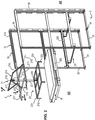
- a stationary storage shelter 1 of at least one electrical energy storage unit U this shelter being equipped with a lifting and handling device 2 of said unit.
- the electrical energy storage units U that are the subject of the present application are preferably electric energy storage batteries, of the LMP® (for Lithium Metal Polymer) type or of the type lithium ions, whose weight is less than 500 kg, preferably of the order of 300 kg to 400 kg.
- This shelter 1 is intended, among other things, to protect U units from bad weather and to provide a stable climatic enclosure.
- the storage shelter 1 is said to be “stationary” in that it rests on the ground and is not loaded on a moving vehicle.
- the stationary shelter 1 is a structure whose general shape is preferably that of a cubic or rectangular parallelepiped.
- the different walls of the shelter 1 delimit together an enclosure 10, inside which is disposed a support structure 3, intended to receive at least one electrical energy storage unit U.
- the shelter 1 has an access opening 11, closed by at least one door, here two swinging doors, referenced 12.
- This structure 3 is made by assembling several profiles, preferably metal, which together define a structure having substantially the shape of a rectangular parallelepiped.
- This support structure 3 is for example made by assembling four vertical uprights 30 with a plurality of longitudinal members 31 and possibly sleepers 32.
- This support structure 3 is integral with the shelter 1 and is preferably fixed on the inner face of one or more wall (s) thereof, for example by means of fixing lugs 34.
- this support structure 3 comprises at least one sliding element 35 for receiving an electrical energy storage unit U, and preferably several of these sliding elements, superimposed on each other, as can be seen on the figure 2 or even juxtaposed in alternative embodiments not shown in the figures.
- the sliding receiving element 35 may be in the form of two slides 350, arranged at the same height, facing each other, each slide bearing a support bracket. of said U. These slides and brackets are shaped so that the U unit can be inserted into the sliding receiving element 35 from above or extracted from above, that is to say vertically.
- the slider 35 may be in the form of a cradle or drawer or other device for receiving the unit U from above.
- the sliding element 35 can slide through the access opening 11 (visible on the figure 1 ), between a position called “retracted” inside the shelter 1, which is that represented for example in the upper part or the lower part of the figure 1 , and a so-called “output” position outside the shelter 1, which is the one represented for the unit U placed in the center on the figure 1 .
- the sliding element 35 may optionally comprise locking means in the extended position, such as a latch for example.
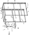
- the support structure 3 comprises at least one fixed reception element 36, preferably several reception elements 36 superimposed (or juxtaposed in embodiments not shown).
- Each receiving element 36 comprises, for example, two parallel support brackets 360, arranged so that their horizontal wings are situated at the same height, opposite each other, and spaced apart by a distance corresponding at least to width of the electrical energy storage unit U.
- brackets 360 can also be replaced for example by a shelf or by fixed guide rails in which slides a rolling member (such as a pad or a wheel), secured to the lateral fins of the unit U.
- the brackets 360 may be coated at least in part with a layer of material facilitating the sliding of the unit U, such as a polymer material with a low friction surface, for example polytetrafluoroethylene (or PTFE). This layer of material can also be arranged under the lateral fins of the unit U.
- the unit U is then inserted into the receiving element 36 by horizontal sliding on the brackets 360, from the rear AR of the shelter to the front AV, and is extracted in a reverse motion.
- the lifting and handling device 2 is disposed inside the shelter 1, above the receiving element 35 or 36 located highest in the shelter, so as to load a storage unit of electrical energy U in it or unload it.
- the lifting and handling device 2 comprises a fixed part integral with the inner wall of said shelter and a movable part, configured to be movable between a so-called “retracted” position, in which it is completely inside. shelter 1, and a so-called “working” position, in which it is outside of this shelter 1, so as to allow the loading and unloading of the unit U in and out of the element 35, 36.
- the movable portion of the lifting and handling device 2 comprises a bracket 21, 24 or 26 according to the embodiments, a hoist (or winch) 22 and a hooking tool 23 or 25 of the unit U.
- the hoist or winch 22 may be manual or motorized.
- the attachment tool may be a lifting frame 23 (shown in FIG. figure 2 ) or a fork 25 (shown on the figure 3 ).
- the lifting frame 23 will now be described in more detail. It preferably has at its four corners 231 chains or hooks or rods 232, for hanging four points of an electrical energy storage unit U and move it vertically while maintaining it horizontally. This frame 23 is also provided at its center with an attachment point 233 to the hoist 22, such as a ring.
- the fork 25, visible on the figure 3 is provided with two horizontal parallel branches 251 capable of being slid under an electrical energy storage unit U.
- This fork 25 also comprises at its upper part an attachment point 252 (such as a hook or a ring) hoist or winch 22.
- the frame 23 and the fork 25 are further shaped to withstand the movement of heavy loads, preferably less than about 500 kg, the U units generally having weights between 300 and 400 kg, as mentioned above.
- the lifting frame 23 is used when the receiving element is sliding (element 35) and that the loading and / or unloading of the unit U is effected by the top of this element 35.
- the fork 25 is used when the receiving element is fixed (element 36) and the loading and / or unloading of the unit U is carried out by the rear (AR side) and horizontally, that is, ie by sliding on the brackets 360.
- a first embodiment of the lifting and handling device 2 will now be described in connection with the figure 4 .
- the fixed part of the device 2 comprises in this case two guide rails 260 fixed respectively on the inner faces facing each other of the two upper longitudinal members 31 of the support device 3.
- the sliding stem 26 comprises two parallel slides 261, interconnected by at least one crosspiece 262. Each slide 261 is movable in translation in one of the guide rails 260, so that the bracket 26 can perform a displacement in horizontal translation , in both ways.
- the stem 26 can adopt the working position shown on the figure 4 (arrow F) or the retracted position (arrow G), in which the slides 261 are completely housed in the rails 260.
- the crossbar is provided with a suspension means of the hoist or winch 22 (not shown in this figure ), such as a ring or hook 263.
- the fixed part of the lifting device 2 comprises two parallel guide rails 210 respectively fixed on the inner faces of the two upper longitudinal members 31 of the support structure 3.
- the sliding stem 21 comprises two parallel sliders 211, interconnected by at least one cross member 212, preferably located near the free end of the two sliders, that is to say the rear AR side of the shelter 1 .
- the sliders 211 move in the guide rails 210 (see arrows F and G).
- the sliding stem 21 also comprises a bow 214.
- this hoop 214 has the shape of an inverted U. This form is not limiting.
- the hoop 214 further comprises suspension means hoist or winch 22, such as a ring or a hook 213, preferably arranged at its center.
- Each of the two ends 215 of the arch 214 is pivotally mounted about a pivot axis 216 integral with one of the slides 211.
- the hoop 214 is mounted so that its two ends 215 are facing forward AV of the shelter.
- the hoop 214 can thus pivot between a folded working position, in which it extends in a horizontal plane (arrow I), and an extended working position, shown in FIG. figure 2 (arrow H), in which it is inclined with respect to the horizontal (from the top and the back to the bottom and the front to the figure 2 ). In this latter position, the ring 213 carried by the arch 214 is raised, which makes it easier to hang the hoist 22 to load the unit U into the receiving element 35 the highest.
- the hoop 214 is provided with immobilization means 217 in its deployed working position.
- these immobilizing means 217 consist of at least one pivotally mounted stand at one of its two ends (here its rearwardly facing end AR of the shelter 1), relative to 212. The pivoting is performed about an axis 218 carried by the cross member 212.
- This crutch 217 is provided at its other end with locking means 219 on the hoop 214, such as for example a hook or a finger cooperating with an orifice formed in the hoop 214.
- the stand 217 can be folded into an inactive position in which it does not cooperate with the hoop 214. It can also be deployed in an active position, which is the one shown in FIG. figure 2 , in which it is locked with the hoop 214, so as to maintain it in its deployed working position.
- a third embodiment of the lifting and handling device 2 will now be described in connection with the figure 3 .
- the device 2 comprises a single central guide rail 240 fixed for example between two upper cross members 32 of the support structure 3, so that its guide face is oriented downwards.
- the sliding bracket 24 comprises a slide 241, movable in translation relative to said rail 240 (arrows F and G), and this slide 241 comprises, at its free end, suspension means 242 of the hoist or winch 22, such as a ring or a hook.
- the slide 241 also comprises a translational member 243, such as a carriage, which then supports the suspension means 242 of the hoist or winch.
- a translational member 243 such as a carriage
- this trolley 243 could also be replaced by a telescopic portion of the slider 241.
- the fixed guide rails 210, 240, 260 could be fixed directly on the inner face of the walls of the shelter and not on the support structure 3.
- the fact that the fixed part 210, 240, 260 is "fixed" to the outer wall of the shelter 1 generally designates the connection between this fixed part and the inside of the shelter 1, that this mechanical connection is direct or indirect (for example via the support structure 3).
- each lifting and handling device 2 may comprise locking means in the working position which make it possible to ensure that the bracket remains stationary in translation during attachment of the hoist 22 of the tool. 23, 25 and unit U, and subsequently during the vertical movement of the unit U.
- These locking means may be for example a locking finger or a pivoting lever.
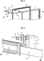
- a first possible embodiment of the locking means is represented for example on the figure 5 .
- These locking means referenced 4 comprise a hollow tubular sleeve 41 bevelled, attached to the front end of the slider 211, for example by means of a bracket 42.
- the sleeve 41 is perpendicular to the direction of movement of the slider 211.
- a locking pin 43 comprising a rod 431 provided with an operating handle 432 is inserted with a slight sliding and pivoting play in the sleeve 41.
- the rod 431 is mounted in the sleeve 41 with a non-visible return spring.
- the rod 431 can thus be moved by the operator between a "locked” position, represented on the figure 5 , in which it enters a bore 301 formed in a rear upright 30 thus guaranteeing the locking of the slider 211 in the working position of the device 2 and an "unlocked" position, not shown, in which the operator rotates the rod 431 a quarter of a turn, so that the lever 432 slides along the bevel of the sleeve 41 and the rod 431 out of the bore 301. In the latter case, the movable portion 21 of the device 2 is in the retracted position in the shelter 1.
- the spring tends to return the rod 431 in the locked position.
- a second embodiment of the locking means bearing the reference 5 is represented on the figure 6 .
- These means 5 comprise a pivoting lever 51 and a locking pin 52.
- the locking pin 52 is fixed on the upright 30 and the lever 51 is fixed close to the front end of the slide 211.
- the pivoting lever 51 is equipped with a notch 510 in which the pin 52 can penetrate.
- the operator can hook it on the pin 52 and thus block the slider 211 of the device 2 in the working position or on the contrary spread the lever 51 of the pin 52 and thus allow the movement of the device 2 in retracted position.
- an inverted arrangement is also possible, that is to say the locking pin 43 or the lever 51 on the support 3 and the bore 301 or the pin 52 on the slider 211.
- the method of loading an electrical energy storage unit U inside the shelter 1 is as follows.
- the operator deposits the box C (see figure 1 ) containing the electrical energy storage unit U using appropriate tools in front of the shelter 1. It opens the box C and stows the attachment tool 23 or 25 to the unit U. It sliding the mobile stem 21, 24, 26 out of the shelter 1, hooks the hoist or winch 22 and moves the bracket so as to bring it above the unit U. It then hangs the hoist, or the winch 22, to the hooking tool 23, 25 above. If necessary, the operator moves the carriage 243 forward AV (arrow J) or rearward AR (arrow K).
- the operator can then by acting on the hoist or winch 22 lift the unit U and move it to insert it into the receiving element, either from above or from its rear end. He can then detach the tool 23, 25 from the unit U and put away inside the shelter 1 the lifting and handling device 2.
- This device 2 is still in position. Only one person suffices to perform this maneuver. In addition, from a safety point of view, there is no longer a risk related to the state of the loading zone that extends around the shelter.
Landscapes
- Chemical & Material Sciences (AREA)
- Chemical Kinetics & Catalysis (AREA)
- Electrochemistry (AREA)
- General Chemical & Material Sciences (AREA)
- Engineering & Computer Science (AREA)
- Civil Engineering (AREA)
- Structural Engineering (AREA)
- Mechanical Engineering (AREA)
- Tents Or Canopies (AREA)
- Types And Forms Of Lifts (AREA)
Description
L'invention se situe dans le domaine des installations électriques autonomes et stationnaires, c'est-à-dire des installations fixes, qui couplent des moyens de production d'énergie, tel que des panneaux solaires ou des éoliennes par exemple, avec des unités de stockage de l'énergie électrique ainsi produite.The invention is in the field of autonomous and stationary electrical installations, that is to say fixed installations, which couple energy production means, such as solar panels or wind turbines for example, with units storing the electrical energy thus produced.
L'invention concerne plus particulièrement un abri stationnaire de stockage d'au moins une telle unité de stockage d'énergie électrique, cet abri contenant au moins un élément de réception de ladite unité et étant équipé d'un dispositif de levage et de manutention de cette unité.The invention relates more particularly to a stationary shelter for storing at least one such electrical energy storage unit, this shelter containing at least one receiving element of said unit and being equipped with a device for lifting and handling this unit.
Les installations électriques précitées sont destinées à être installées dans des zones reculées, difficiles d'accès, par exemple mais non exclusivement en Afrique.The aforementioned electrical installations are intended to be installed in remote areas, difficult to access, for example but not exclusively in Africa.
Des "abris", connus sous la dénomination anglaise de "shelters", permettent de loger non seulement un ensemble d'unités de stockage d'énergie, mais également divers dispositifs assurant la gestion électronique de leur fonctionnement et de leur sécurité."Shelters", known as " shelters ", allow to house not only a set of energy storage units, but also various devices ensuring the electronic management of their operation and their security.
On connait ainsi des abris stationnaires de stockage d'au moins une unité de stockage d'énergie électrique, qui comprennent au moins un emplacement de réception de ladite unité, de préférence plusieurs superposés et/ou juxtaposés.Stationary storage shelters are thus known from at least one electrical energy storage unit, which comprise at least one location for receiving said unit, preferably several superimposed and / or juxtaposed.
En pratique, l'introduction des unités de stockage dans l'abri stationnaire s'effectue comme suit. Lesdites unités sont transportées dans des caisses. Un transporteur décharge lesdites caisses à proximité de l'abri. Les caisses sont ouvertes, puis l'opérateur à l'aide d'un chariot élévateur manuel ou motorisé insère lesdites unités dans l'abri stationnaire.In practice, the introduction of the storage units in the stationary shelter is as follows. Said units are transported in crates. A carrier unloads said crates near the shelter. The crates are open, then the operator using a manual or motorized forklift inserts the units into the stationary shelter.
Toutefois, cette opération nécessite d'amener un chariot élévateur à proximité de l'abri stationnaire et de prévoir autour de ce dernier une zone de chargement adaptée au chariot élévateur, en termes de nivellement du sol et de nature de celui-ci.However, this operation requires bringing a forklift near the stationary shelter and to provide around the latter a loading area adapted to the forklift, in terms of leveling the soil and nature of it.
Lorsque l'abri de stockage est installé dans des zones d'accès difficile, il peut se trouver sur tout type de terrain, par exemple accidenté, caillouteux, il peut même être sur le sol à une hauteur différente de celle à laquelle se trouve le chariot élévateur. Dans ces différents cas, et en prenant également en compte les conditions météorologiques, la demanderesse a constaté que le chargement et le déchargement des unités de stockage d'énergie électrique dans et hors de l'abri de stockage peuvent s'avérer dangereux et très complexes.When the storage shelter is installed in areas of difficult access, it can be on any type of terrain, for example rugged, stony, it can even be on the ground at a height different from that at which the forklift. In these different cases, and also taking into account the meteorological conditions, the Applicant has found that the loading and unloading of electrical energy storage units in and out of the storage shed can be dangerous and very complex. .
En outre, il faut tenir compte du fait que ces unités peuvent être assez lourdes, par exemple de l'ordre de 300 kg à 400 kg, voire 500 kg.In addition, it must be taken into account that these units can be quite heavy, for example of the order of 300 kg to 400 kg or 500 kg.
On connaît déjà d'après le document
On connaît enfin d'après le document
L'invention a donc pour but de résoudre les inconvénients précités de l'état de la technique et notamment de permettre un chargement ou un déchargement des unités de stockage d'énergie électrique dans et hors de l'abri, qui soit sécurisé pour l'opérateur, sans risques d'endommagements de cet unité ou de cet abri, et ce, même si le terrain situé autour de l'abri ne permet pas d'y amener un chariot élévateur.The invention therefore aims to solve the aforementioned drawbacks of the state of the art and in particular to allow loading or unloading of electrical energy storage units in and out of the shelter, which is secured for the operator, without risk of damage to this unit or shelter, even if the terrain around the shelter does not allow to bring a forklift.
L'invention a également pour but de simplifier ces opérations de manutention et de permettre leur mise en oeuvre avec peu d'outils et un seul opérateur.The invention also aims to simplify these handling operations and allow their implementation with few tools and a single operator.
A cet effet, l'invention concerne un abri stationnaire de stockage d'au moins une unité de stockage d'énergie électrique.For this purpose, the invention relates to a stationary shelter for storing at least one electrical energy storage unit.
Conformément à l'invention, cet abri comprend au moins un élément de réception de ladite unité, conformé pour que ladite unité de stockage d'énergie électrique puisse y être insérée ou en être extraite, et ce, au travers d'une ouverture d'accès ménagée dans une paroi dudit abri stationnaire, ledit abri comprend un dispositif de levage et de manutention de ladite unité, ce dispositif de levage et de manutention est disposé à l'intérieur dudit abri, au-dessus de l'élément de réception situé le plus haut dans l'abri et le dispositif de levage et de manutention comprend une partie fixe solidaire d'au moins une paroi intérieure dudit abri et une partie mobile configurée pour pouvoir être déplacée entre une position dite escamotée, dans laquelle elle rentre complètement à l'intérieur dudit abri, et une position dite de travail, dans laquelle elle se trouve à l'extérieur dudit abri et dans laquelle elle permet le chargement et le déchargement d'une unité de stockage d'énergie électrique dans et hors de l'élément de réception.According to the invention, this shelter comprises at least one receiving element of said unit, shaped so that said electrical energy storage unit can be inserted into or extracted from it, and this, through an opening of access provided in a wall of said stationary shelter, said shelter comprises a device for lifting and handling said unit, this lifting and handling device is disposed inside said shelter, above the receiving element located on the higher in the shelter and the lifting and handling device comprises a fixed part secured to at least one inner wall of said shelter and a movable portion configured to be movable between a so-called retracted position, in which it fully returns to the interior of said shelter, and a so-called working position, in which it is outside said shelter and in which it allows the loading and unloading of a unit storing electrical energy in and out of the receiving element.
Grâce à ces caractéristiques de l'invention, il n'est plus nécessaire d'avoir un chariot élévateur pour introduire les unités de stockage d'énergie électrique dans l'abri stationnaire.Thanks to these features of the invention, it is no longer necessary to have a forklift to introduce the electrical energy storage units in the stationary shelter.
Les caisses contenant les unités sont déposées devant l'abri et le dispositif de levage et de manutention intégré à l'intérieur de l'abri permet leur chargement et leur déchargement dans et hors de l'abri.The boxes containing the units are placed in front of the shelter and the integrated lifting and handling device inside the shelter allows them to be loaded and unloaded in and out of the shelter.
De plus, le dispositif de levage étant intégré dans l'abri, il est à la fois parfaitement adapté aux unités de stockage d'énergie électrique à manipuler et toujours disponible sur le site. Il n'y a plus de risque que l'utilisateur oublie le matériel de déchargement, ou ait un matériel non adapté.In addition, the lifting device being integrated into the shelter, it is both perfectly adapted to the electrical energy storage units to handle and always available on the site. There is no more risk that the user forgets the unloading equipment, or has an unsuitable material.
Enfin, le dispositif de levage est protégé des intempéries puisqu'il est stocké à l'intérieur de l'abri pendant toute la période où il n'est pas utilisé.Finally, the lifting device is protected from bad weather since it is stored inside the shelter during the entire period when it is not used.
Selon d'autres caractéristiques avantageuses et non limitatives de l'invention, prises seules ou en combinaison :
- ladite partie fixe comprend au moins un rail de guidage et ladite partie mobile comprend une potence coulissante, un palan, ou un treuil, et un outil d'accrochage de l'unité de stockage d'énergie électrique, ladite potence étant équipée de moyens de suspension du palan ou treuil et l'outil d'accrochage étant configuré pour pouvoir être fixé audit palan ou treuil, et ladite potence coulissante est configurée pour pouvoir se déplacer en translation par rapport audit rail de guidage entre la position escamotée et la position de travail ;
- la partie fixe du dispositif de levage comprend deux rails de guidage parallèles et la potence coulissante comprend deux coulisseaux parallèles, reliés entre eux par au moins une traverse, chaque coulisseau étant mobile en translation par rapport à l'un desdits rails de guidage et ladite traverse comprenant des moyens de suspension du palan ou treuil, tel qu'un anneau ou un crochet ;
- la partie fixe du dispositif de levage comprend deux rails de guidage parallèles, la potence coulissante comprend un arceau et deux coulisseaux parallèles, reliés entre eux par au moins une traverse, l'arceau comprenant des moyens de suspension du palan ou treuil, tel qu'un anneau ou un crochet, chaque coulisseau étant mobile en translation par rapport à l'un desdits rails de guidage, et chacune des deux extrémités de l'arceau est montée pivotante par rapport à l'un des coulisseaux de sorte que ledit arceau peut occuper une position de travail repliée, dans laquelle il s'étend dans un plan horizontal, et une position de travail déployée, dans laquelle il est incliné par rapport à l'horizontale, de façon à se trouver au-dessus du plan horizontal passant par lesdits deux coulisseaux ;
- le dispositif de levage et de manutention comprend des moyens d'immobilisation de l'arceau dans ladite position de travail déployée ;
- lesdits moyens d'immobilisation comportent au moins une béquille montée pivotante à l'une de ses deux extrémités par rapport à la traverse reliant entre eux lesdits deux coulisseaux, cette béquille étant munie à son autre extrémité de moyens de verrouillage sur l'arceau, et ladite béquille peut passer d'une position inactive dans laquelle elle ne coopère pas avec l'arceau, à une position active, dans laquelle elle est verrouillée avec l'arceau, de façon à maintenir celui-ci dans sa position de travail déployée ;
- la partie fixe du dispositif de levage comprend un rail de guidage et la potence coulissante comprend un coulisseau mobile en translation par rapport audit rail de guidage, ledit coulisseau comprenant des moyens de suspension du palan ou treuil, tel qu'un anneau ou un crochet ;
- ledit coulisseau comprend un élément mobile en translation, tel qu'un chariot, ou une portion de coulisseau télescopique, le palan ou treuil étant fixé à cet élément mobile en translation ;
- ledit outil d'accrochage de l'unité de stockage d'énergie électrique est un cadre muni en son centre d'un point de fixation au palan ou treuil et à ses quatre coins de moyens d'accrochage de ladite unité ;
- ledit outil d'accrochage de l'unité de stockage d'énergie électrique est une fourche munie à son extrémité supérieure d'un point de fixation au palan ou treuil ;
- la partie mobile du dispositif de levage et de manutention comprend des moyens de blocage en position de travail ;
- ledit au moins un élément de réception est coulissant, de sorte qu'il peut coulisser au travers de ladite ouverture d'accès entre une position rentrée à l'intérieur dudit abri et une position sortie à l'extérieur de celui-ci, et cet élément de réception coulissant est conformé pour que ladite unité de stockage d'énergie électrique puisse y être insérée ou en être extraite par le haut, lorsqu'il est en position sortie ;
- ledit au moins un élément de réception coulissant comprend des moyens de verrouillage en position sortie ;
- ledit au moins un élément de réception est fixe à l'intérieur de l'abri et est conformé pour que ladite unité de stockage d'énergie électrique puisse y être insérée ou en être extraite par son extrémité débouchant en regard de ladite ouverture d'accès ;
- ledit élément de réception comprend deux équerres parallèles disposées l'une en face de l'autre et à la même hauteur ; et
- lesdites équerres sont revêtues au moins en partie par une couche de matériau facilitant l'introduction et le coulissement de ladite unité dans ledit élément de réception.
- said fixed part comprises at least one guide rail and said movable part comprises a sliding stem, a hoist, or a winch, and a hooking tool of the electric energy storage unit, said bracket being equipped with suspension of the hoist or winch and the attachment tool being configured to be fixed to said hoist or winch, and said sliding bracket is configured to be able to move in translation relative to said guide rail between the retracted position and the working position;
- the fixed part of the lifting device comprises two parallel guide rails and the sliding bracket comprises two parallel slides, connected to each other by at least one crosspiece, each slide being movable in translation relative to one of said guide rails and said crossbar; comprising means for suspending the hoist or winch, such as a ring or a hook;
- the fixed part of the lifting device comprises two parallel guide rails, the sliding stem comprises a bow and two parallel slides, connected to each other by at least one cross member, the bow including suspension means of the hoist or winch, such as a ring or a hook, each slide being movable in translation relative to one of said guide rails, and each of the two ends of the arch is pivotally mounted relative to one of the slides so that said arch can occupy a folded working position, in which it extends in a horizontal plane, and an extended working position, in which it is inclined with respect to the horizontal, so as to be above the horizontal plane passing through the said two sliders;
- the lifting and handling device comprises means for immobilizing the hoop in said deployed working position;
- said immobilizing means comprise at least one stand pivotally mounted at one of its two ends with respect to the cross member interconnecting said two slides, this stand being provided at its other end with locking means on the hoop, and said stand can move from an inactive position in which it does not cooperate with the hoop, to an active position, in which it is locked with the hoop, so as to keep it in its deployed working position;
- the fixed part of the lifting device comprises a guide rail and the sliding bracket comprises a slide movable in translation relative to said guide rail, said slide comprising suspension means hoist or winch, such as a ring or a hook;
- said slider comprises a member movable in translation, such as a carriage, or a telescopic slider portion, the hoist or winch being fixed to said movable member in translation;
- said attachment tool of the electrical energy storage unit is a frame provided at its center with a point of attachment to the hoist or winch and at its four corners of attachment means of said unit;
- said attachment tool of the electrical energy storage unit is a fork provided at its upper end with a point of attachment to the hoist or winch;
- the moving part of the lifting and handling device comprises locking means in the working position;
- said at least one receiving element is slidable, so that it can slide through said access opening between a retracted position inside said shelter and an outward position thereof, and this sliding receiving element is shaped so that said electrical energy storage unit can be inserted or extracted from above, when in the extended position;
- said at least one sliding receiving element comprises locking means in the extended position;
- said at least one receiving element is fixed inside the shelter and is shaped so that said electrical energy storage unit can be inserted into or extracted from its end opening opposite said access opening ;
- said receiving element comprises two parallel brackets arranged opposite one another and at the same height; and
- said brackets are coated at least in part by a layer of material facilitating the introduction and sliding of said unit in said receiving element.
D'autres caractéristiques et avantages de l'invention apparaîtront de la description qui va maintenant en être faite, en référence aux dessins annexés, qui en représentent, à titre indicatif mais non limitatif, des modes de réalisation possibles.Other features and advantages of the invention will appear from the description which will now be made, with reference to the accompanying drawings, which represent, by way of indication but not limitation, possible embodiments.
Sur ces dessins :
- la
figure 1 est une vue en perspective représentant un abri stationnaire de stockage conforme à l'invention, équipé d'un dispositif de levage et de manutention, - la
figure 2 est une vue en perspective d'une structure de support comprenant le dispositif de levage et de manutention conforme à l'invention, cette structure de support étant représentée hors de l'abri stationnaire, - la
figure 3 est une vue similaire à lafigure 2 mais représentant un autre mode de réalisation du dispositif de levage et de manutention, - la
figure 4 est une vue en perspective de la partie supérieure de la structure de support équipée d'une variante de réalisation du dispositif de levage et de manutention de lafigure 2 , et - Les
figures 5 et6 sont des vues en perspective de deux modes de réalisation possibles des moyens de blocage du dispositif de levage et de manutention en position de travail.
- the
figure 1 is a perspective view showing a stationary storage shelter according to the invention, equipped with a lifting and handling device, - the
figure 2 is a perspective view of a support structure comprising the lifting and handling device according to the invention, this support structure being shown outside the stationary shelter, - the
figure 3 is a view similar to thefigure 2 but representing another embodiment of the lifting and handling device, - the
figure 4 is a perspective view of the upper part of the support structure equipped with an alternative embodiment of the lifting and handling device of thefigure 2 , and - The
figures 5 and6 are perspective views of two possible embodiments of the locking means of the lifting device and handling in the working position.
En se reportant à la
Sans que cela soit limitatif, on notera que les unités de stockage d'énergie électrique U dont il est question dans la présente demande sont préférentiellement des batteries de stockage d'énergie électrique, du type LMP® (pour Lithium Métal Polymère) ou du type lithium ions, dont le poids est inférieur à 500 kg, de préférence de l'ordre de 300 kg à 400 kg.Without this being limiting, it will be noted that the electrical energy storage units U that are the subject of the present application are preferably electric energy storage batteries, of the LMP® (for Lithium Metal Polymer) type or of the type lithium ions, whose weight is less than 500 kg, preferably of the order of 300 kg to 400 kg.
Cet abri 1 est destiné, entre autres, à protéger les unités U des intempéries et à offrir une enceinte climatique stable.This shelter 1 is intended, among other things, to protect U units from bad weather and to provide a stable climatic enclosure.
L'abri de stockage 1 est dit "stationnaire", en ce sens qu'il repose sur le sol et n'est pas embarqué sur un véhicule mobile.The storage shelter 1 is said to be "stationary" in that it rests on the ground and is not loaded on a moving vehicle.
L'abri stationnaire 1 est une structure dont la forme générale est de préférence celle d'un parallélépipède cubique ou rectangle.The stationary shelter 1 is a structure whose general shape is preferably that of a cubic or rectangular parallelepiped.
Les différentes parois de l'abri 1 délimitent ensemble une enceinte 10, à l'intérieur de laquelle est disposée une structure de support 3, destinée à recevoir au moins une unité de stockage d'énergie électrique U.The different walls of the shelter 1 delimit together an enclosure 10, inside which is disposed a
L'abri 1 présente une ouverture d'accès 11, obturée par au moins une porte, ici deux portes battantes, référencées 12.The shelter 1 has an
Par convention, on dénomme avant AV, le côté de l'abri 1 par lequel un opérateur peut pénétrer, et arrière AR, le côté opposé, qui est également celui par lequel les unités U peuvent être introduites dans l'abri 1 ou en être extraites.By convention, one denominates before AV, the side of the shelter 1 by which an operator can enter, and back AR, the opposite side, which is also the one by which the U units can be introduced into the shelter 1 or be extracted.
Un exemple de réalisation de la structure de support 3 va maintenant être décrit en liaison avec la
Cette structure de support 3 est par exemple réalisée en assemblant quatre montants verticaux 30 avec une pluralité de longerons 31 et éventuellement des traverses 32.This
Cette structure de support 3 est solidaire de l'abri 1 et elle est préférentiellement fixée sur la face intérieure d'une ou de plusieurs paroi(s) de celui-ci, par exemple à l'aide de pattes de fixation 34.This
Selon un premier mode de réalisation de l'invention, représenté sur la
On notera que, lorsqu'il y a plusieurs colonnes d'éléments coulissants de réception 35 superposés, il y a un dispositif de levage et de manutention 2 au-dessus de chaque colonne.It should be noted that when there are several columns of superposed receiving sliding members, there is a lifting and
Dans son mode de réalisation le plus simple, l'élément de réception coulissant 35 peut se présenter sous la forme de deux glissières 350, disposées à la même hauteur, l'une en face de l'autre, chaque glissière portant une équerre de support de ladite unité U. Ces glissières et équerres sont conformées pour que l'unité U puisse être insérée dans l'élément de réception coulissant 35 par le haut ou en être extraite par le haut, c'est-à-dire verticalement.In its simplest embodiment, the sliding receiving
Dans des modes de réalisation plus élaborés, l'élément coulissant 35 peut se présenter sous la forme d'un berceau ou d'un tiroir ou de tout autre dispositif permettant la réception de l'unité U par le haut.In more elaborate embodiments, the
Quel que soit le mode de réalisation de l'élément coulissant 35, celui-ci peut coulisser au travers de l'ouverture d'accès 11 (visible sur la
L'élément coulissant 35 peut éventuellement comprendre des moyens de verrouillage en position sortie, tel qu'un loquet par exemple.The sliding
Selon un second mode de réalisation de l'invention, représenté sur la
Ces deux équerres 360 peuvent également être remplacées par exemple par une étagère ou par des rails de guidage fixes dans lesquels vient coulisser un organe de roulement (tel qu'un patin ou une roue), solidaire d'ailettes latérales de l'unité U. De façon avantageuse, les équerres 360 peuvent être revêtues au moins en partie d'une couche de matériau facilitant le glissement de l'unité U, tel qu'un matériau polymère à faible surface de frottement, par exemple du polytétrafluoroéthylène (ou PTFE). Cette couche de matériau peut également être disposée sous les ailettes latérales de l'unité U.These two
Dans ce second mode de réalisation de l'invention, l'unité U est alors insérée dans l'élément de réception 36 par coulissement horizontal sur les équerres 360, depuis l'arrière AR de l'abri vers l'avant AV, et en est extraite selon un mouvement inverse.In this second embodiment of the invention, the unit U is then inserted into the receiving
On notera également que la partie fixe de la glissière 350 (
Le dispositif de levage et de manutention 2 est disposé à l'intérieur de l'abri 1, au-dessus de l'élément de réception 35 ou 36 situé le plus haut dans l'abri, de façon à pouvoir charger une unité de stockage d'énergie électrique U dans celui-ci ou l'en décharger.The lifting and
Par ailleurs, le dispositif de levage et de manutention 2 comprend une partie fixe solidaire de la paroi intérieure dudit abri et une partie mobile, configurée pour pouvoir être déplacée entre une position dite "escamotée", dans laquelle elle se trouve complètement à l'intérieur de l'abri 1, et une position dite "de travail", dans laquelle elle se trouve à l'extérieur de cet abri 1, de façon à permettre le chargement et le déchargement de l'unité U dans et hors de l'élément de réception 35, 36.Furthermore, the lifting and
D'une manière générale, la partie mobile du dispositif de levage et de manutention 2 comprend une potence 21, 24 ou 26 suivant les modes de réalisation, un palan (ou un treuil) 22 et un outil d'accrochage 23 ou 25 de l'unité U.In general, the movable portion of the lifting and
Le palan ou le treuil 22 peut être manuel ou motorisé.The hoist or
L'outil d'accrochage peut être un cadre de levage 23 (représenté sur la
Le cadre de levage 23 va maintenant être décrit plus en détails. Il présente préférentiellement à ses quatre coins 231 des chaînes ou crochets ou tiges 232, permettant d'accrocher quatre points d'une unité de stockage d'énergie électrique U et de la déplacer verticalement tout en la maintenant horizontalement. Ce cadre 23 est également muni en son centre d'un point de fixation 233 au palan 22, tel qu'un anneau.The lifting
La fourche 25, visible sur la
Le cadre 23 et la fourche 25 sont en outre conformés pour résister au déplacement de charges lourdes, de préférence inférieures à 500 kg environ, les unités U ayant généralement des poids compris entre 300 et 400 kg, comme mentionné précédemment.The
On notera que le cadre de levage 23 est utilisé lorsque l'élément de réception est coulissant (élément 35) et que le chargement et/ou déchargement de l'unité U s'effectue par le dessus de cet élément 35.It will be noted that the lifting
Inversement, la fourche 25 est utilisée lorsque l'élément de réception est fixe (élément 36) et que le chargement et/ou déchargement de l'unité U s'effectue par l'arrière (côté AR) et horizontalement, c'est-à-dire par coulissement sur les équerres 360.Conversely, the
Un premier mode de réalisation du dispositif de levage et de manutention 2 va maintenant être décrit en liaison avec la
La partie fixe du dispositif 2 comprend dans ce cas deux rails de guidage 260 fixés respectivement sur les faces intérieures se faisant face des deux longerons supérieurs 31 du dispositif de support 3.The fixed part of the
La potence coulissante 26 comprend deux coulisseaux parallèles 261, reliés entre eux par au moins une traverse 262. Chaque coulisseau 261 est mobile en translation dans l'un des rails de guidage 260, de sorte que la potence 26 peut effectuer un déplacement en translation horizontale, dans les deux sens. La potence 26 peut adopter la position de travail représentée sur la
Un deuxième mode de réalisation du dispositif 2 va maintenant être décrit en liaison avec la
Dans ce cas, la partie fixe du dispositif de levage 2 comprend deux rails de guidage parallèles 210 fixés respectivement sur les faces intérieures des deux longerons supérieurs 31 de la structure de support 3.In this case, the fixed part of the
La potence coulissante 21 comprend deux coulisseaux parallèles 211, reliés entre eux par au moins une traverse 212, située de préférence à proximité de l'extrémité libre des deux coulisseaux, c'est-à-dire du côté arrière AR de l'abri 1.The sliding
Les coulisseaux 211 se déplacent dans les rails de guidage 210 (voir les flèches F et G).The
La potence coulissante 21 comprend également un arceau 214. Dans l'exemple représenté sur la
De préférence, et comme représenté sur la
L'arceau 214 peut ainsi pivoter entre une position de travail repliée, dans laquelle il s'étend dans un plan horizontal (flèche I), et une position de travail déployée, représentée sur la
De façon avantageuse, l'arceau 214 est muni de moyens 217 d'immobilisation dans sa position de travail déployée.Advantageously, the
Selon une variante de réalisation possible, ces moyens d'immobilisation 217 sont constitués d'au moins une béquille montée pivotante à l'une de ses deux extrémités (ici son extrémité orientée vers l'arrière AR de l'abri 1), par rapport à la traverse 212. Le pivotement s'effectue autour d'un axe 218 porté par la traverse 212.According to a possible variant embodiment, these immobilizing means 217 consist of at least one pivotally mounted stand at one of its two ends (here its rearwardly facing end AR of the shelter 1), relative to 212. The pivoting is performed about an
Cette béquille 217 est munie, à son autre extrémité, de moyens de verrouillage 219 sur l'arceau 214, tels que par exemple un crochet ou un doigt coopérant avec un orifice ménagé dans l'arceau 214.This
La béquille 217 peut être rabattue dans une position inactive dans laquelle elle ne coopère pas avec l'arceau 214. Elle peut aussi être déployée dans une position active, qui est celle représentée sur la
Un troisième mode de réalisation du dispositif de levage et de manutention 2 va maintenant être décrit en liaison avec la
Dans ce cas, le dispositif 2 comprend un unique rail de guidage central 240 fixé par exemple entre deux traverses supérieures 32 de la structure de support 3, de façon que sa face de guidage soit orientée vers le bas.In this case, the
Par ailleurs, la potence coulissante 24 comprend un coulisseau 241, mobile en translation par rapport audit rail 240 (flèches F et G), et ce coulisseau 241 comprend, à son extrémité libre, des moyens de suspension 242 du palan ou du treuil 22, tels qu'un anneau ou un crochet.Furthermore, the sliding
Selon une variante de réalisation qui est celle représentée sur la
Dans les différents modes de réalisation du dispositif de levage et de manutention 2 qui viennent d'être décrits, on notera que les rails de guidage fixes 210, 240, 260 pourraient être fixés directement sur la face interne des parois de l'abri et non sur la structure de support 3.In the various embodiments of the lifting and
On notera que le fait que la partie fixe 210, 240, 260 soit « solidaire » de la paroi extérieure de l'abri 1 désigne d'une manière générale la liaison entre cette partie fixe et l'intérieur de l'abri 1, que cette liaison mécanique soit directe ou indirecte (par exemple par l'intermédiaire de la structure de support 3).It will be noted that the fact that the
Par ailleurs, la partie mobile de chaque dispositif de levage et de manutention 2 peut comprendre des moyens de blocage en position de travail qui permettent de s'assurer que la potence reste immobile en translation pendant l'accrochage du palan 22, de l'outil d'accrochage 23, 25 et de l'unité U, puis ultérieurement pendant le mouvement de déplacement vertical de l'unité U.Furthermore, the movable part of each lifting and
Ces moyens de blocage peuvent être par exemple un doigt de verrouillage ou un levier pivotant.These locking means may be for example a locking finger or a pivoting lever.
Un premier mode de réalisation possible des moyens de blocage est représenté par exemple sur la
Ces moyens de blocage référencés 4 comprennent un manchon tubulaire creux 41 biseauté, fixé à l'extrémité avant du coulisseau 211, par exemple à l'aide d'une patte de fixation 42. Le manchon 41 est perpendiculaire à la direction de déplacement du coulisseau 211.These locking means referenced 4 comprise a hollow
Un doigt de verrouillage 43 comprenant une tige 431 munie d'une manette de manoeuvre 432 est inséré avec un léger jeu de coulissement et de pivotement dans le manchon 41. La tige 431 est montée dans le manchon 41 avec un ressort de rappel non visible.A locking
La tige 431 peut ainsi être déplacée par l'opérateur entre une position « verrouillée », représentée sur la
Le ressort tend à ramener la tige 431 en position verrouillée.The spring tends to return the
Un second mode de réalisation des moyens de blocage portant la référence 5 est représenté sur la
Ces moyens 5 comprennent un levier pivotant 51 et un pion de verrouillage 52. Le pion de verrouillage 52 est fixé sur le montant 30 et le levier 51 est fixé à proximité de l'extrémité avant du coulisseau 211. Le levier pivotant 51 est muni d'une encoche 510 dans laquelle le pion 52 peut pénétrer.These means 5 comprise a pivoting
En faisant pivoter manuellement le levier 51, l'opérateur peut l'accrocher sur le pion 52 et ainsi bloquer le coulisseau 211 du dispositif 2 en position de travail ou au contraire écarter le levier 51 du pion 52 et ainsi autoriser le déplacement du dispositif 2 en position escamotée.By manually rotating the
D'autres modes de réalisation des moyens de blocage sont envisageables sans pour autant sortir du cadre de l'invention.Other embodiments of the locking means are conceivable without departing from the scope of the invention.
Dans les modes de réalisation précédemment décrits, un montage inversé est également possible, c'est-à-dire le doigt de verrouillage 43 ou le levier 51 sur le support 3 et le perçage 301 ou le pion 52 sur le coulisseau 211.In the embodiments described above, an inverted arrangement is also possible, that is to say the locking
Enfin, ce qui a été décrit avec le coulisseau 211 peut être envisagé avec les coulisseaux 241 ou 261.Finally, what has been described with the
Le procédé de chargement d'une unité de stockage d'énergie électrique U à l'intérieur de l'abri 1 est le suivant.The method of loading an electrical energy storage unit U inside the shelter 1 is as follows.
L'opérateur dépose la caisse C (voir
L'opérateur peut ensuite en agissant sur le palan ou treuil 22 soulever l'unité U et la déplacer pour l'insérer dans l'élément de réception, soit par le dessus, soit par son extrémité arrière. Il peut alors détacher l'outil 23, 25 de l'unité U et ranger à l'intérieur de l'abri 1 le dispositif de levage et de manutention 2.The operator can then by acting on the hoist or
Ce dispositif 2 est toujours à poste. Une seule personne suffit pour effectuer cette manoeuvre. De plus, d'un point de vue de la sécurité, il n'y a plus de risque lié à l'état de la zone de chargement qui s'étend autour de l'abri.This
Claims (16)
- A stationary shelter (1) for storing at least one electrical energy storage unit (U), said shelter (1) comprising at least one element (35, 36) for receiving said unit, shaped so that said electrical energy storage unit (U) can be inserted therein or extracted therefrom, and this through an access opening (11) formed in a wall of said stationary shelter (1), said shelter (1) further comprising a device (2) for lifting and handling said unit (U), said shelter (1) being characterized in that this lifting and handling device (2) is disposed inside said shelter (1), above the receiving element (35, 36) located uppermost in the shelter (1) and in that the lifting and handling device (2) comprises a fixed part (210, 240, 260) secured to least one inner wall of said shelter (1) and one movable part (21, 22, 23, 24, 25, 26) configured to be moved between a position called stowed position, in which it fits completely inside said shelter (1), and a position called working position, in which it is located outside said shelter (1) and in which it allows the loading and unloading of an electrical energy storage unit (U) in and out of the receiving element (35, 36).
- The shelter (1) according to claim 1, characterized in that said fixed part comprises at least one guide rail (210, 240, 260), in that said movable part comprises a sliding gallows (21, 24, 26), a hoist (22), or a winch, and a tool (23, 25) for hooking the electrical energy storage unit (U), said gallows (21, 24, 26) being equipped with means (213, 242, 263) for suspending the hoist or winch (22) and the hooking tool (23, 25) being configured to be attached to said hoist or winch (22), and in that said sliding gallows (21, 24, 26) is configured to move in translation with respect to said guide rail (210, 240, 260) between the stowed position and the working position.
- The shelter (1) according to claim 2, characterized in that the fixed part of the lifting device (2) comprises two parallel guide rails (260) and in that the sliding gallows (26) comprises two parallel sliders (261), connected together by at least one cross-member (262), each slider (261) being movable in translation with respect to one of said guide rails (260) and said cross-member (262) comprising means for suspending the hoist or winch (22), such as a ring or a hook (263).
- The shelter (1) according to claim 2, characterized in that the fixed part of the lifting device (2) comprises two parallel guide rails (210), in that the sliding gallows (21) comprises a hoop (214) and two parallel sliders (211), connected together by at least one cross-member (212), the hoop (214) comprising means for suspending the hoist or winch (22), such as a ring or a hook (213), each slider (211) being movable in translation with respect to one of said guide rails (210), and in that each of the two ends (215) of the hoop (214) is pivotally mounted relative to one of the sliders (211) so that said hoop (214) can occupy a folded working position, in which it extends in a horizontal plane, and a deployed working position, in which it is inclined relative to the horizontal, so as to be above the horizontal plane passing through said two sliders (211).
- The shelter (1) according to claim 4, characterized in that the lifting and handling device (2) comprises means (217) for immobilizing the hoop (214) in said deployed working position.
- The shelter according to claim 5, characterized in that said immobilizing means include at least one strut (217) pivotally mounted at one of its two ends relative to the cross-member (212) connecting therebetween said two sliders (211), this strut (217) being provided at its other end with locking means (219) on the hoop (214), and in that said strut (217) can switch from an inactive position in which it does not cooperate with the hoop (214) to an active position in which it is locked with the hoop (214), so as to maintain it in its deployed working position.
- The shelter (1) according to claim 2, characterized in that the fixed part of the lifting device (2) comprises a guide rail (240) and in that the sliding gallows (24) comprises a slider (241) movable in translation with respect to said guide rail (240), said slider (241) comprising means (242) for suspending the hoist or winch (22), such as a ring or a hook.
- The shelter (1) according to claim 7, characterized in that said slider (241) comprises an element movable in translation (243), such as a truck, or a portion of a telescopic slider, the hoist or winch (22) being attached to this element movable in translation (243).
- The shelter (1) according to any of claims 2 to 8, characterized in that said tool for hooking the electrical energy storage unit (U) is a frame (23) provided, at its center, with a point (233) of attachment to the hoist (22) or winch and, at its four corners (231), with means (232) for hooking said unit (U) .
- The shelter (1) according to any of claims 2 to 8, characterized in that said tool for hooking the electrical energy storage unit (U) is a fork (25) provided at its upper end with a point (252) of attachment to the hoist (22) or winch.
- The shelter (1) according to any of the preceding claims, characterized in that the movable part of the lifting and handling device (2) comprises blocking means in the working position.
- The shelter (1) according to any of the preceding claims, characterized in that said at least one receiving element (35) is slidable, so it can slide through said access opening (11) between a retracted position inside said shelter (1) and an extended position thereoutside, and in that this sliding receiving element (35) is shaped so that said electrical energy storage unit (U) can be inserted therein or extracted therefrom through the top, when it is in the extended position.
- The shelter (1) according to claim 12, characterized in that said at least one sliding receiving element (35) comprises locking means in the extended position.
- The shelter (1) according to any of claims 1 to 11, characterized in that said at least one receiving element (36) is attached inside the shelter (1) and is shaped so that said electrical energy storage unit (U) can be inserted therein or extracted therefrom through its end opening facing said access opening (11).
- The shelter (1) according to claim 14, characterized in that said receiving element (36) comprises two parallel brackets (360) disposed facing each other and at the same height.
- The shelter (1) according to claim 15, characterized in that said brackets (360) are coated at least partly with a layer of material facilitating the introduction and the sliding of said unit (U) in said receiving element (36).
Applications Claiming Priority (2)
| Application Number | Priority Date | Filing Date | Title |
|---|---|---|---|
| FR1650050A FR3046430B1 (en) | 2016-01-05 | 2016-01-05 | STATIONARY SHELTER FOR STORING AT LEAST ONE ELECTRIC ENERGY STORAGE UNIT |
| PCT/EP2017/050104 WO2017118644A1 (en) | 2016-01-05 | 2017-01-04 | Stationary shelter for storing at least one electrical energy storage unit |
Publications (2)
| Publication Number | Publication Date |
|---|---|
| EP3400622A1 EP3400622A1 (en) | 2018-11-14 |
| EP3400622B1 true EP3400622B1 (en) | 2019-11-13 |
Family
ID=55862938
Family Applications (1)
| Application Number | Title | Priority Date | Filing Date |
|---|---|---|---|
| EP17700045.2A Active EP3400622B1 (en) | 2016-01-05 | 2017-01-04 | Stationary shelter for storing at least one electrical energy storage unit |
Country Status (3)
| Country | Link |
|---|---|
| EP (1) | EP3400622B1 (en) |
| FR (1) | FR3046430B1 (en) |
| WO (1) | WO2017118644A1 (en) |
Families Citing this family (2)
| Publication number | Priority date | Publication date | Assignee | Title |
|---|---|---|---|---|
| CN111641242A (en) * | 2020-06-30 | 2020-09-08 | 广州视睿电子科技有限公司 | Charging cabinet |
| TWI738527B (en) * | 2020-09-25 | 2021-09-01 | 神雲科技股份有限公司 | Server system |
Family Cites Families (2)
| Publication number | Priority date | Publication date | Assignee | Title |
|---|---|---|---|---|
| US4126232A (en) * | 1977-06-02 | 1978-11-21 | Westinghouse Electric Corp. | Electrical switchboard apparatus with integral traveling lifting mechanism |
| DE9305524U1 (en) * | 1993-04-13 | 1994-09-01 | Gottlob Auwärter GmbH & Co, 70567 Stuttgart | Exchange station for electric road vehicles equipped with exchangeable batteries |
-
2016
- 2016-01-05 FR FR1650050A patent/FR3046430B1/en active Active
-
2017
- 2017-01-04 WO PCT/EP2017/050104 patent/WO2017118644A1/en active Application Filing
- 2017-01-04 EP EP17700045.2A patent/EP3400622B1/en active Active
Also Published As
| Publication number | Publication date |
|---|---|
| FR3046430B1 (en) | 2018-01-12 |
| FR3046430A1 (en) | 2017-07-07 |
| EP3400622A1 (en) | 2018-11-14 |
| WO2017118644A1 (en) | 2017-07-13 |
Similar Documents
| Publication | Publication Date | Title |
|---|---|---|
| EP3199306B1 (en) | Storage device for tools | |
| EP3838666B1 (en) | Support for lifting container by upper holes of the container | |
| WO2006120347A1 (en) | Lifting work bench | |
| EP3400622B1 (en) | Stationary shelter for storing at least one electrical energy storage unit | |
| EP0558367A1 (en) | Structure permitting loading and unloading of transport containers with a hydraulic grappling device | |
| EP3400190B1 (en) | Stationary shelter for storing at least one electrical energy storage unit | |
| FR2913668A1 (en) | Bag i.e. big-bag, filling assisting device for use during e.g. interior work in building, has posts articulated at base, where each post is equipped with hooking unit to hook handle of bag and to maintain bag open in suspended position | |
| EP2927160B1 (en) | All-door construction skip comprising a retractable control spreader and having reduced width | |
| FR3059692A1 (en) | DEVICE FOR HANDLING A FORMWORK PANEL | |
| EP0326767A1 (en) | Retractable shelves for storage or transport container and like containers equipped with such shelves | |
| EP2162371B1 (en) | Equipment comprising an apparatus for receiving a structure capable of being taken up by a carrier vehicle equipped with a handling arm or ramp | |
| OA18743A (en) | Abri stationnaire de stockage d'au moins une unité de stockage d'énergie électrique | |
| FR2561601A1 (en) | Trolley of the ''barrow'' type for transporting objects such as suitcases | |
| CH484827A (en) | Auxiliary trolley allowing the use of a front fork lift as a side fork lift | |
| FR2674810A1 (en) | Trolley for handling a load equipped with wheels | |
| FR2563204A1 (en) | ATTACHMENT FOR FORK TROLLEY, AND UNLOADING METHOD USING THE SAME | |
| BE1009110A4 (en) | Carriage charge. | |
| EP3978333B1 (en) | Handling cart with manual movement | |
| EP3254319B1 (en) | Stationary shelter for storing at least one energy storage element | |
| FR2785251A1 (en) | Trolley for carrying merchandise has collapsible shelving frame attached to trapezoidal wheeled base | |
| EP0749921B1 (en) | Dolly for transporting, stacking, handling and mounting of vertical and flat elements | |
| FR2904611A1 (en) | Object e.g. precast wall, transporting device for use with e.g. industrial trailer, has stabilizing unit extended with respect to sides of support for stabilizing device, and return unit to return stabilizing unit to extension position | |
| EP0434880A1 (en) | Handling device for a load carried by a vehicle | |
| FR2620994A1 (en) | Trolley intended for transporting various goods | |
| FR3043394B1 (en) | SYSTEM FOR PACKING A FORKLIFT UNDER A PLATFORM FOR LOADING A TRANSPORT VEHICLE |
Legal Events
| Date | Code | Title | Description |
|---|---|---|---|
| STAA | Information on the status of an ep patent application or granted ep patent |
Free format text: STATUS: UNKNOWN |
|
| STAA | Information on the status of an ep patent application or granted ep patent |
Free format text: STATUS: THE INTERNATIONAL PUBLICATION HAS BEEN MADE |
|
| PUAI | Public reference made under article 153(3) epc to a published international application that has entered the european phase |
Free format text: ORIGINAL CODE: 0009012 |
|
| STAA | Information on the status of an ep patent application or granted ep patent |
Free format text: STATUS: REQUEST FOR EXAMINATION WAS MADE |
|
| 17P | Request for examination filed |
Effective date: 20180802 |
|
| AK | Designated contracting states |
Kind code of ref document: A1 Designated state(s): AL AT BE BG CH CY CZ DE DK EE ES FI FR GB GR HR HU IE IS IT LI LT LU LV MC MK MT NL NO PL PT RO RS SE SI SK SM TR |
|
| AX | Request for extension of the european patent |
Extension state: BA ME |
|
| DAV | Request for validation of the european patent (deleted) | ||
| DAX | Request for extension of the european patent (deleted) | ||
| REG | Reference to a national code |
Ref country code: DE Ref legal event code: R079 Ref document number: 602017008675 Country of ref document: DE Free format text: PREVIOUS MAIN CLASS: H01M0002100000 Ipc: B66C0005040000 |
|
| RIC1 | Information provided on ipc code assigned before grant |
Ipc: E04H 5/04 20060101ALI20190411BHEP Ipc: H01M 2/10 20060101ALI20190411BHEP Ipc: B66C 5/04 20060101AFI20190411BHEP |
|
| GRAP | Despatch of communication of intention to grant a patent |
Free format text: ORIGINAL CODE: EPIDOSNIGR1 |
|
| STAA | Information on the status of an ep patent application or granted ep patent |
Free format text: STATUS: GRANT OF PATENT IS INTENDED |
|
| INTG | Intention to grant announced |
Effective date: 20190605 |
|
| GRAS | Grant fee paid |
Free format text: ORIGINAL CODE: EPIDOSNIGR3 |
|
| GRAA | (expected) grant |
Free format text: ORIGINAL CODE: 0009210 |
|
| STAA | Information on the status of an ep patent application or granted ep patent |
Free format text: STATUS: THE PATENT HAS BEEN GRANTED |
|
| AK | Designated contracting states |
Kind code of ref document: B1 Designated state(s): AL AT BE BG CH CY CZ DE DK EE ES FI FR GB GR HR HU IE IS IT LI LT LU LV MC MK MT NL NO PL PT RO RS SE SI SK SM TR |
|
| REG | Reference to a national code |
Ref country code: AT Ref legal event code: REF Ref document number: 1201448 Country of ref document: AT Kind code of ref document: T Effective date: 20191115 Ref country code: CH Ref legal event code: EP |
|
| REG | Reference to a national code |
Ref country code: DE Ref legal event code: R096 Ref document number: 602017008675 Country of ref document: DE |
|
| REG | Reference to a national code |
Ref country code: IE Ref legal event code: FG4D Free format text: LANGUAGE OF EP DOCUMENT: FRENCH |
|
| REG | Reference to a national code |
Ref country code: HK Ref legal event code: DE Ref document number: 1260292 Country of ref document: HK |
|
| REG | Reference to a national code |
Ref country code: NL Ref legal event code: MP Effective date: 20191113 |
|
| REG | Reference to a national code |
Ref country code: LT Ref legal event code: MG4D |
|
| PG25 | Lapsed in a contracting state [announced via postgrant information from national office to epo] |
Ref country code: GR Free format text: LAPSE BECAUSE OF FAILURE TO SUBMIT A TRANSLATION OF THE DESCRIPTION OR TO PAY THE FEE WITHIN THE PRESCRIBED TIME-LIMIT Effective date: 20200214 Ref country code: PL Free format text: LAPSE BECAUSE OF FAILURE TO SUBMIT A TRANSLATION OF THE DESCRIPTION OR TO PAY THE FEE WITHIN THE PRESCRIBED TIME-LIMIT Effective date: 20191113 Ref country code: LV Free format text: LAPSE BECAUSE OF FAILURE TO SUBMIT A TRANSLATION OF THE DESCRIPTION OR TO PAY THE FEE WITHIN THE PRESCRIBED TIME-LIMIT Effective date: 20191113 Ref country code: PT Free format text: LAPSE BECAUSE OF FAILURE TO SUBMIT A TRANSLATION OF THE DESCRIPTION OR TO PAY THE FEE WITHIN THE PRESCRIBED TIME-LIMIT Effective date: 20200313 Ref country code: FI Free format text: LAPSE BECAUSE OF FAILURE TO SUBMIT A TRANSLATION OF THE DESCRIPTION OR TO PAY THE FEE WITHIN THE PRESCRIBED TIME-LIMIT Effective date: 20191113 Ref country code: SE Free format text: LAPSE BECAUSE OF FAILURE TO SUBMIT A TRANSLATION OF THE DESCRIPTION OR TO PAY THE FEE WITHIN THE PRESCRIBED TIME-LIMIT Effective date: 20191113 Ref country code: NL Free format text: LAPSE BECAUSE OF FAILURE TO SUBMIT A TRANSLATION OF THE DESCRIPTION OR TO PAY THE FEE WITHIN THE PRESCRIBED TIME-LIMIT Effective date: 20191113 Ref country code: BG Free format text: LAPSE BECAUSE OF FAILURE TO SUBMIT A TRANSLATION OF THE DESCRIPTION OR TO PAY THE FEE WITHIN THE PRESCRIBED TIME-LIMIT Effective date: 20200213 Ref country code: LT Free format text: LAPSE BECAUSE OF FAILURE TO SUBMIT A TRANSLATION OF THE DESCRIPTION OR TO PAY THE FEE WITHIN THE PRESCRIBED TIME-LIMIT Effective date: 20191113 Ref country code: NO Free format text: LAPSE BECAUSE OF FAILURE TO SUBMIT A TRANSLATION OF THE DESCRIPTION OR TO PAY THE FEE WITHIN THE PRESCRIBED TIME-LIMIT Effective date: 20200213 |
|
| PGFP | Annual fee paid to national office [announced via postgrant information from national office to epo] |
Ref country code: DE Payment date: 20200123 Year of fee payment: 4 |
|
| PG25 | Lapsed in a contracting state [announced via postgrant information from national office to epo] |
Ref country code: RS Free format text: LAPSE BECAUSE OF FAILURE TO SUBMIT A TRANSLATION OF THE DESCRIPTION OR TO PAY THE FEE WITHIN THE PRESCRIBED TIME-LIMIT Effective date: 20191113 Ref country code: IS Free format text: LAPSE BECAUSE OF FAILURE TO SUBMIT A TRANSLATION OF THE DESCRIPTION OR TO PAY THE FEE WITHIN THE PRESCRIBED TIME-LIMIT Effective date: 20200313 Ref country code: HR Free format text: LAPSE BECAUSE OF FAILURE TO SUBMIT A TRANSLATION OF THE DESCRIPTION OR TO PAY THE FEE WITHIN THE PRESCRIBED TIME-LIMIT Effective date: 20191113 |
|
| PG25 | Lapsed in a contracting state [announced via postgrant information from national office to epo] |
Ref country code: AL Free format text: LAPSE BECAUSE OF FAILURE TO SUBMIT A TRANSLATION OF THE DESCRIPTION OR TO PAY THE FEE WITHIN THE PRESCRIBED TIME-LIMIT Effective date: 20191113 |
|
| PGFP | Annual fee paid to national office [announced via postgrant information from national office to epo] |
Ref country code: FR Payment date: 20200110 Year of fee payment: 4 |
|
| PG25 | Lapsed in a contracting state [announced via postgrant information from national office to epo] |
Ref country code: DK Free format text: LAPSE BECAUSE OF FAILURE TO SUBMIT A TRANSLATION OF THE DESCRIPTION OR TO PAY THE FEE WITHIN THE PRESCRIBED TIME-LIMIT Effective date: 20191113 Ref country code: EE Free format text: LAPSE BECAUSE OF FAILURE TO SUBMIT A TRANSLATION OF THE DESCRIPTION OR TO PAY THE FEE WITHIN THE PRESCRIBED TIME-LIMIT Effective date: 20191113 Ref country code: ES Free format text: LAPSE BECAUSE OF FAILURE TO SUBMIT A TRANSLATION OF THE DESCRIPTION OR TO PAY THE FEE WITHIN THE PRESCRIBED TIME-LIMIT Effective date: 20191113 Ref country code: RO Free format text: LAPSE BECAUSE OF FAILURE TO SUBMIT A TRANSLATION OF THE DESCRIPTION OR TO PAY THE FEE WITHIN THE PRESCRIBED TIME-LIMIT Effective date: 20191113 Ref country code: CZ Free format text: LAPSE BECAUSE OF FAILURE TO SUBMIT A TRANSLATION OF THE DESCRIPTION OR TO PAY THE FEE WITHIN THE PRESCRIBED TIME-LIMIT Effective date: 20191113 |
|
| REG | Reference to a national code |
Ref country code: DE Ref legal event code: R097 Ref document number: 602017008675 Country of ref document: DE |
|
| REG | Reference to a national code |
Ref country code: AT Ref legal event code: MK05 Ref document number: 1201448 Country of ref document: AT Kind code of ref document: T Effective date: 20191113 |
|
| PG25 | Lapsed in a contracting state [announced via postgrant information from national office to epo] |
Ref country code: SK Free format text: LAPSE BECAUSE OF FAILURE TO SUBMIT A TRANSLATION OF THE DESCRIPTION OR TO PAY THE FEE WITHIN THE PRESCRIBED TIME-LIMIT Effective date: 20191113 Ref country code: SM Free format text: LAPSE BECAUSE OF FAILURE TO SUBMIT A TRANSLATION OF THE DESCRIPTION OR TO PAY THE FEE WITHIN THE PRESCRIBED TIME-LIMIT Effective date: 20191113 Ref country code: MC Free format text: LAPSE BECAUSE OF FAILURE TO SUBMIT A TRANSLATION OF THE DESCRIPTION OR TO PAY THE FEE WITHIN THE PRESCRIBED TIME-LIMIT Effective date: 20191113 |
|
| REG | Reference to a national code |
Ref country code: CH Ref legal event code: PL |
|
| PLBE | No opposition filed within time limit |
Free format text: ORIGINAL CODE: 0009261 |
|
| STAA | Information on the status of an ep patent application or granted ep patent |
Free format text: STATUS: NO OPPOSITION FILED WITHIN TIME LIMIT |
|
| REG | Reference to a national code |
Ref country code: BE Ref legal event code: MM Effective date: 20200131 |
|
| 26N | No opposition filed |
Effective date: 20200814 |
|
| PG25 | Lapsed in a contracting state [announced via postgrant information from national office to epo] |
Ref country code: LU Free format text: LAPSE BECAUSE OF NON-PAYMENT OF DUE FEES Effective date: 20200104 |
|
| PG25 | Lapsed in a contracting state [announced via postgrant information from national office to epo] |
Ref country code: SI Free format text: LAPSE BECAUSE OF FAILURE TO SUBMIT A TRANSLATION OF THE DESCRIPTION OR TO PAY THE FEE WITHIN THE PRESCRIBED TIME-LIMIT Effective date: 20191113 Ref country code: BE Free format text: LAPSE BECAUSE OF NON-PAYMENT OF DUE FEES Effective date: 20200131 Ref country code: CH Free format text: LAPSE BECAUSE OF NON-PAYMENT OF DUE FEES Effective date: 20200131 Ref country code: LI Free format text: LAPSE BECAUSE OF NON-PAYMENT OF DUE FEES Effective date: 20200131 Ref country code: AT Free format text: LAPSE BECAUSE OF FAILURE TO SUBMIT A TRANSLATION OF THE DESCRIPTION OR TO PAY THE FEE WITHIN THE PRESCRIBED TIME-LIMIT Effective date: 20191113 |
|
| PG25 | Lapsed in a contracting state [announced via postgrant information from national office to epo] |
Ref country code: IE Free format text: LAPSE BECAUSE OF NON-PAYMENT OF DUE FEES Effective date: 20200104 Ref country code: IT Free format text: LAPSE BECAUSE OF FAILURE TO SUBMIT A TRANSLATION OF THE DESCRIPTION OR TO PAY THE FEE WITHIN THE PRESCRIBED TIME-LIMIT Effective date: 20191113 |
|
| REG | Reference to a national code |
Ref country code: DE Ref legal event code: R119 Ref document number: 602017008675 Country of ref document: DE |
|
| GBPC | Gb: european patent ceased through non-payment of renewal fee |
Effective date: 20210104 |
|
| PG25 | Lapsed in a contracting state [announced via postgrant information from national office to epo] |
Ref country code: FR Free format text: LAPSE BECAUSE OF NON-PAYMENT OF DUE FEES Effective date: 20210131 |
|
| PG25 | Lapsed in a contracting state [announced via postgrant information from national office to epo] |
Ref country code: DE Free format text: LAPSE BECAUSE OF NON-PAYMENT OF DUE FEES Effective date: 20210803 Ref country code: GB Free format text: LAPSE BECAUSE OF NON-PAYMENT OF DUE FEES Effective date: 20210104 |
|
| PG25 | Lapsed in a contracting state [announced via postgrant information from national office to epo] |
Ref country code: TR Free format text: LAPSE BECAUSE OF FAILURE TO SUBMIT A TRANSLATION OF THE DESCRIPTION OR TO PAY THE FEE WITHIN THE PRESCRIBED TIME-LIMIT Effective date: 20191113 Ref country code: MT Free format text: LAPSE BECAUSE OF FAILURE TO SUBMIT A TRANSLATION OF THE DESCRIPTION OR TO PAY THE FEE WITHIN THE PRESCRIBED TIME-LIMIT Effective date: 20191113 Ref country code: CY Free format text: LAPSE BECAUSE OF FAILURE TO SUBMIT A TRANSLATION OF THE DESCRIPTION OR TO PAY THE FEE WITHIN THE PRESCRIBED TIME-LIMIT Effective date: 20191113 |
|
| PG25 | Lapsed in a contracting state [announced via postgrant information from national office to epo] |
Ref country code: MK Free format text: LAPSE BECAUSE OF FAILURE TO SUBMIT A TRANSLATION OF THE DESCRIPTION OR TO PAY THE FEE WITHIN THE PRESCRIBED TIME-LIMIT Effective date: 20191113 |