EP3399532A1 - Emergency stop device - Google Patents
Emergency stop device Download PDFInfo
- Publication number
- EP3399532A1 EP3399532A1 EP18166986.2A EP18166986A EP3399532A1 EP 3399532 A1 EP3399532 A1 EP 3399532A1 EP 18166986 A EP18166986 A EP 18166986A EP 3399532 A1 EP3399532 A1 EP 3399532A1
- Authority
- EP
- European Patent Office
- Prior art keywords
- pusher
- actuating
- triggering
- unlocking
- control knob
- Prior art date
- Legal status (The legal status is an assumption and is not a legal conclusion. Google has not performed a legal analysis and makes no representation as to the accuracy of the status listed.)
- Granted
Links
Images


Classifications
-
- H—ELECTRICITY
- H01—ELECTRIC ELEMENTS
- H01H—ELECTRIC SWITCHES; RELAYS; SELECTORS; EMERGENCY PROTECTIVE DEVICES
- H01H3/00—Mechanisms for operating contacts
- H01H3/02—Operating parts, i.e. for operating driving mechanism by a mechanical force external to the switch
- H01H3/022—Emergency operating parts, e.g. for stop-switch in dangerous conditions
-
- G—PHYSICS
- G05—CONTROLLING; REGULATING
- G05G—CONTROL DEVICES OR SYSTEMS INSOFAR AS CHARACTERISED BY MECHANICAL FEATURES ONLY
- G05G1/00—Controlling members, e.g. knobs or handles; Assemblies or arrangements thereof; Indicating position of controlling members
- G05G1/015—Arrangements for indicating the position of a controlling member
-
- G—PHYSICS
- G05—CONTROLLING; REGULATING
- G05G—CONTROL DEVICES OR SYSTEMS INSOFAR AS CHARACTERISED BY MECHANICAL FEATURES ONLY
- G05G1/00—Controlling members, e.g. knobs or handles; Assemblies or arrangements thereof; Indicating position of controlling members
- G05G1/02—Controlling members for hand actuation by linear movement, e.g. push buttons
- G05G1/025—Controlling members for hand actuation by linear movement, e.g. push buttons actuated by sliding movement
-
- G—PHYSICS
- G05—CONTROLLING; REGULATING
- G05G—CONTROL DEVICES OR SYSTEMS INSOFAR AS CHARACTERISED BY MECHANICAL FEATURES ONLY
- G05G5/00—Means for preventing, limiting or returning the movements of parts of a control mechanism, e.g. locking controlling member
- G05G5/04—Stops for limiting movement of members, e.g. adjustable stop
-
- G—PHYSICS
- G05—CONTROLLING; REGULATING
- G05G—CONTROL DEVICES OR SYSTEMS INSOFAR AS CHARACTERISED BY MECHANICAL FEATURES ONLY
- G05G5/00—Means for preventing, limiting or returning the movements of parts of a control mechanism, e.g. locking controlling member
- G05G5/05—Means for returning or tending to return controlling members to an inoperative or neutral position, e.g. by providing return springs or resilient end-stops
-
- H—ELECTRICITY
- H01—ELECTRIC ELEMENTS
- H01H—ELECTRIC SWITCHES; RELAYS; SELECTORS; EMERGENCY PROTECTIVE DEVICES
- H01H25/00—Switches with compound movement of handle or other operating part
- H01H25/06—Operating part movable both angularly and rectilinearly, the rectilinear movement being along the axis of angular movement
- H01H25/065—Operating part movable both angularly and rectilinearly, the rectilinear movement being along the axis of angular movement using separate operating parts, e.g. a push button surrounded by a rotating knob
-
- H—ELECTRICITY
- H01—ELECTRIC ELEMENTS
- H01H—ELECTRIC SWITCHES; RELAYS; SELECTORS; EMERGENCY PROTECTIVE DEVICES
- H01H9/00—Details of switching devices, not covered by groups H01H1/00 - H01H7/00
- H01H9/16—Indicators for switching condition, e.g. "on" or "off"
-
- H—ELECTRICITY
- H01—ELECTRIC ELEMENTS
- H01H—ELECTRIC SWITCHES; RELAYS; SELECTORS; EMERGENCY PROTECTIVE DEVICES
- H01H3/00—Mechanisms for operating contacts
- H01H3/02—Operating parts, i.e. for operating driving mechanism by a mechanical force external to the switch
- H01H3/022—Emergency operating parts, e.g. for stop-switch in dangerous conditions
- H01H2003/0246—Resetting of bistable emergency operating part by rotating itself or an accessory
-
- H—ELECTRICITY
- H01—ELECTRIC ELEMENTS
- H01H—ELECTRIC SWITCHES; RELAYS; SELECTORS; EMERGENCY PROTECTIVE DEVICES
- H01H2219/00—Legends
- H01H2219/036—Light emitting elements
-
- H—ELECTRICITY
- H01—ELECTRIC ELEMENTS
- H01H—ELECTRIC SWITCHES; RELAYS; SELECTORS; EMERGENCY PROTECTIVE DEVICES
- H01H2219/00—Legends
- H01H2219/054—Optical elements
- H01H2219/062—Light conductor
- H01H2219/0622—Light conductor only an illuminated ring around keys
-
- H—ELECTRICITY
- H01—ELECTRIC ELEMENTS
- H01H—ELECTRIC SWITCHES; RELAYS; SELECTORS; EMERGENCY PROTECTIVE DEVICES
- H01H2235/00—Springs
- H01H2235/004—Two parallel coil springs
Definitions
- the present invention relates to an emergency stop device, in particular having improved architecture and improved sealing.
- a known emergency stop device as described for example in the document US7790996 comprises a control button movable in translation between two positions along a control axis and capable of actuating a pusher cooperating with an electrical contact unit.
- the control knob is rotated.
- the button To be easily manipulated, the button must have a shape that allows it to be easily gripped relative to the rest of the device. It therefore often takes a particularly prominent shape, which increases its size in depth.
- the patent EP2700080B1 describes a more compact emergency stop device.
- the unlocking function is provided by a rotating ring, independent of the button.
- the rotation of the ring serves to initiate the unlocking to return the actuating button to the initial position of rest.
- the return to the initial position is then ensured by the spring (R1 in this document) which is also used to trigger the device.
- the triggering function of the device is indeed provided by two springs (R1, R2) whose stiffness constants are adjusted relative to each other.
- the stiffness of the main spring (R1) must take into account the stiffness of the other spring (R2) and is chosen relatively low to give the emergency stop device the desired sensitivity. It can not be increased without deteriorating the overall operation of the device.
- the object of the invention is therefore to provide an emergency stop device in which the unlocking function for the return of the control button to the initial rest position is particularly reliable and implemented without prejudice to the trigger function.
- the solution of the invention also makes it possible to regulate certain other disadvantages of the prior devices, in particular in terms of sealing the device.
- the body comprises an inner housing supporting the actuating assembly and an outer housing supporting the unlocking assembly.
- the outer casing has a crown shape having a tubular portion on which is mounted said unlocking ring.
- said control knob is slidably mounted in said tubular portion of the outer casing and the device comprises a first seal arranged between said control button and said outer casing.
- the inner housing has a flared upper part and a lower part.
- the actuating pusher is slidably mounted in said upper part of the inner casing and the device comprises a second seal arranged between said actuating pusher and said inner casing.
- the actuating pusher is fixed to said control button.
- the triggering pusher is assembled on the actuating pusher according to a mechanical link of the slide type.
- the device comprises a printed circuit housed in said outer casing.
- the device comprises a light assembly connected to said printed circuit.
- the device comprises an attachment member mounted on the trigger and movable between a latching position in which it cooperates with a stop of the body to lock the trigger push in an actuated position and a retracted position in which it is released from said stop to allow the return of the trigger to a rest position.
- the device comprises a set of electrical contacts arranged to cooperate with said triggering pusher.
- an emergency stop device 1 is for controlling an electric circuit and can be actuated by an operator to open the electrical circuit in case of emergency.
- the emergency stop device 1 of the invention may be mounted through an opening of standard diameter (for example diameter 22mm or 30mm) made in a wall or in a mounting box fixed on the wall or embedded in the wall.
- an attachment ring 25 will for example be used to ensure the attachment of the device on the wall.
- the front side of the wall is defined as the side of which the control knob is accessible and the back side of the wall as the side where the set of electrical contacts is placed.
- control axis (X) we define a control axis (X) according to which the moving parts of the device 1 are actuated in translation.
- the terms “upper”, “lower”, “high” or “low” are to be understood by taking the control axis (X) as a reference in a vertical direction.
- the emergency stop device of the invention comprises a body. It will be considered below that all the parts of the device which are fixed during operation of the device are part of the body.
- the body advantageously comprises an inner casing 14 on which is assembled in particular the actuating assembly and an outer casing 13 assembled on the inner casing and on which the unlocking assembly is assembled in particular.
- the outer casing 13 has for example a general shape of a crown comprising a base 130 and a cover 131.
- Said cover 131 advantageously comprises a low crown 132 and a tubular portion 133 extending above the crown 132.
- the inner casing is presents for its part in the form of an independent block coming axially into the axial space in the center of the crown.
- the inner housing 14 has a flared upper portion 140 defining a flange and a lower portion 141, separated from each other by a shoulder. It also has an axial opening over its entire height and an internal sleeve 142 defining a bowl 143 with its flange. Thanks to the inner housing, the actuating assembly advantageously comprises a one-piece structure, that is to say in one piece. The actuating assembly is therefore likely to be easily replaced, without having to touch the rest of the device 1, in particular the assemblies housed in the outer casing 13.
- the control assembly of the emergency stop device comprises a control knob 11, slidably mounted in the tubular portion 133 of the outer casing 13 of the body, so as to be actuable in translation relative to the body of the device according to said control axis (X).
- the control knob 11 is initially in a rest position in which the controlled electric circuit is closed. By pressing inside the device, the control knob 11 is slid into the tubular portion 133 to be brought into an actuated position in which it abuts against the body of the device, thereby allowing the circuit to be positively opened. electric. After actuation, the control button 11 is released but then remains hooked in a so-called actuated-relaxed position, in which the electrical circuit remains open. The electrical circuit remains open until the device is unlocked.
- the control knob 11 advantageously comprises a head 111 on which a pressure can be applied to actuate the device and a shank 112 extending in an axial direction towards the inside of the device and intended to cooperate with the actuating assembly of the device. device.
- the head of the device advantageously comprises a section of non-circular shape, enabling it to cooperate in rotation with the unlocking ring 20.
- the actuating assembly comprises an actuating pusher 12 hooked to the control button 11 by means of fixing members made both on the control button 11 and the actuating pusher.
- fixing members are, for example, latching members, making it possible to snap the actuating pusher onto the tail 112 of the control knob 11.
- the actuating pusher 12 is slidably mounted in the flange of the inner casing 14.
- the actuating pusher 12 is in the form of a cylindrical piece comprising an inner sleeve 120 and an outer sleeve 121 forming between them a bowl 122.
- the actuating pusher 12 also has a flange 123 made on its outer sleeve.
- the actuating assembly comprises an actuating spring R1 bearing on the one hand against the bottom of the bowl 143 of the inner casing and on the other hand against the flange 123 of the actuating pusher 12, so that the actuating pusher 12 is mounted on this actuating spring R1.
- the actuating assembly also comprises a triggering pusher 15.
- This triggering pusher 15 is in the form of a socket which is attached to the actuating pusher 12 while maintaining a degree of freedom in translation in the axial direction. relative to the actuating pusher 12 between two stop positions.
- the actuating assembly comprises a trigger spring R2 bearing firstly at the bottom of the bowl 122 of the actuating pusher 12 and secondly in the bottom 150 of the sleeve formed by the triggering pusher 15 .
- the actuating assembly also comprises a triggering member 16 and an attachment member 17, for example each consisting of a finger which is housed in a radial housing formed on the triggering pusher 15.
- a triggering member 16 and an attachment member 17 are mounted on a helical spring R3, R4 distinct so as to be able to move radially with respect to the control axis (X).
- the triggering member 16 and the hooking member 17 are positioned so as to cooperate each with the inner casing according to the position of the triggering pusher 15.
- the triggering member 16 and the attachment member 17 are susceptible to move in two distinct parallel planes, perpendicular to the control axis (X).
- the plane of translation of the release member 16 is situated above the plane of translation of the fastening member 17.
- the inner casing comprises cam shapes intended to be followed by the trigger member 16 and the attachment member 17, allowing each of these organs to perform their function.
- the triggering member 16 abuts against a stop 144 of the inner casing to lock the movement of the triggering pusher 15 downwards and hold it in the rest position until sufficient energy is stored in the spring of the casing.
- R1 actuation.
- the command button 11 is sufficiently depressed, under the action of a cam formed on the body, the trigger member 16 retracts into its housing, unlocking the trigger pushbutton 15. Under the action of the trigger spring R2, the pusher trigger 15 is driven in translation downwards.
- the control knob 11 After triggering, by the mechanical links existing between both, on the one hand, the triggering pushbutton 15 and the actuating pusher 12 and, on the other hand, between the actuating pusher 12 and the control button 11 the control knob 11 is held in the actuated-released position towards the inside of the body.
- the hooking member 17 cooperates with an abutment 145 made on the inner casing to allow the triggering pusher 15 to be hooked to the body when the control knob 11 is depressed into its actuated position and thus to hold / lock the pusher. 12 and the control knob 11 in the actuated-released position.
- the set of electrical contacts advantageously comprises at least one electrical contact unit 18, generally at least two electrical contact units to ensure redundancy during actuation of the device.
- Each electrical contact unit 18 has a normally closed set of electrical contacts (NC contacts for "Normally Closed”).
- Each contact unit 18 comprises for example a pusher 180 integral with a movable contact bridge intended to be actuated axially by the tail of the triggering pusher.
- the contact units are for example fixed on a base 19 assembled on the body of the device, more specifically directly on the lower part 141 of the inner housing.
- the unlocking assembly comprises an unlocking ring 20 separate from the control button 11, which is rotatably mounted on the outer casing 13 of the body, more precisely on the tubular portion 133 of the outer casing cover.
- the unlocking ring 20 is arranged at the periphery of the control knob 11 and cooperates in rotation with the control knob 11 to unlock it.
- Driving means are arranged between the ring and the control knob to drive the control knob 11 by the unlocking ring 20 when the ring is actuated in rotation. These drive means are for example made by the outer shape of the section of the control knob 11 and the internal shape of the section of the unlocking ring 20.
- the control knob has a substantially square section (Rounded at its vertices) and the ring has a section whose inner shape comes to marry the contour resulting from this square shape.
- the unlocking assembly in addition to the actuating spring R1 and the trigger spring R2, the unlocking assembly comprises a specific spring R5 arranged to drive the control button to its initial rest position.
- This unlocking spring R5 is advantageously housed in the outer casing 13 of the body and is guided by the wall formed of the flange located in the upper part of the inner casing. It has one end attached to the control button 11 and another end attached to the bottom of the outer casing 13. It is advantageously prestressed between its two ends, in translation in the axial direction and in torsion around this axial direction so as to also ensure the return of the ring to its initial position after rotation.
- unlocking ring 20 rotates the control knob 11 which rotates the actuating pusher 12 and the triggering pusher.
- the rotation of the release pusher 15 frees the latching member 17 of the stop made on the body and releases the control knob 11, which, under the action of the unlocking spring R5, is then returned to its position rest.
- the unlocking spring R5 being prestressed in torsion and compression, the return of the control knob 11 to its initial position follows a translational trajectory combined with a rotation.
- the three springs R1, R2, R5 are mounted in spaces arranged concentrically around the control axis (X).
- the spring R2 is located closer to the control axis, the spring R1 is mounted at the periphery of the spring R2 and the spring R5 is mounted at the periphery of the spring R1. This arrangement allows in particular to gain compactness in the direction of the height.
- the two springs R1 and R2 will have to be chosen and adapted to trigger the device when a certain pressure is exerted on the control button.
- the spring R5 will be selected for the return of the control knob to the initial position, independently of the choice of the two springs R1 and R2.
- the unlocking function will therefore be totally independent of the triggering function of the device.
- the emergency stop device advantageously comprises a light assembly completely integrated in the device, assembled on a printed circuit 21 housed in the outer casing 13.
- This light assembly is intended to provide a light signaling function of the stop device. emergency.
- This light assembly comprises for example one or more light-emitting diodes soldered on the printed circuit 21 and connected to power supply units.
- the light assembly is for example controlled to turn yellow or red emergency stop device according to the operating state of the latter.
- the cover 131 of the outer housing 13 may have a transparent ring 132 passing the light of the diodes outwardly. This luminous assembly being housed in the outer casing, its operation does not disturb the operation of the actuating assembly.
- the power supply units of the light-emitting diodes are for example placed on the rear side of the wall and are connected to the diodes by wires passing for example through a hole adjacent to the fixing opening of the device or through the fixing opening of the device.
- device 1 if it is of a size adapted to the passage of the supply son.
- the separation quite distinct from the actuating function and the unlocking function makes it possible to propose a particularly effective sealing solution.
- the outer casing 13 comprises a first sealing solution and the inner casing 14 comprises a second sealing solution.
- the first sealing solution comprises in particular a lip seal 22 arranged in a groove 110 formed on the lateral flank of the control knob 11.
- This lip seal is intended to rub against the inner wall of the tubular portion 133 of the cover 131 of the outer casing 13. It thus ensures sealing in the sliding of the control knob.
- the presence of the specific unlocking spring R5 also makes it possible to return the control knob to its rest position, despite the friction of the lip seal during operation.
- the second sealing solution comprises in particular a lip seal 23 arranged between the actuating pusher 12 and the inner casing 14.
- This lip seal 23 is positioned in abutment against the flange 123 of the actuating pusher 12, on the face opposite to that of the actuating spring.
- This lip seal allows protect the volume defined by the inner housing 14 of the device from any intrusion of dust or liquid, ensuring an always reliable operation of the actuating assembly.
- An additional ring-shaped seal 24 is also positioned under the base 130 of the outer casing.
Abstract
L'invention concerne un dispositif d'arrêt d'urgence comprenant :
- Un bouton de commande (11),
- Un ensemble d'actionnement qui comporte :
- un poussoir d'actionnement (12) coopérant avec ledit bouton de commande et un ressort d'actionnement (R1) monté entre le corps du dispositif et ledit poussoir d'actionnement,
- un poussoir de déclenchement (15) destiné à coopérer avec au moins une unité de contact électrique (18) et un ressort de déclenchement (R2) monté entre ledit poussoir d'actionnement (12) et ledit poussoir de déclenchement (15), et agencé pour solliciter ledit poussoir de déclenchement lorsque le bouton de commande est actionné de sa position de repos vers sa position actionnée,
- un organe d'accrochage monté sur le poussoir de déclenchement (15).
- Un ensemble de déverrouillage comprenant une bague de déverrouillage (20) agencée pour coopérer avec ledit bouton de commande (11) pour le ramener de sa position actionnée relâchée vers la position de repos,
- L'ensemble de déverrouillage comportant un ressort (R5) de déverrouillage monté entre le bouton de commande (11) et le corps et agencé pour solliciter ledit bouton de commande (11) vers sa position de repos.

- a control button (11),
An actuation assembly comprising:
an actuating pusher (12) cooperating with said control knob and an actuating spring (R1) mounted between the body of the device and said actuating pusher,
a triggering pusher (15) intended to cooperate with at least one electrical contact unit (18) and a triggering spring (R2) mounted between said actuation pusher (12) and said triggering pusher (15), and arranged to urge said trigger pusher when the control knob is actuated from its rest position to its actuated position,
- An attachment member mounted on the triggering button (15).
- An unlocking assembly comprising an unlocking ring (20) arranged to cooperate with said control button (11) to bring it back from its actuated position released to the rest position,
- The unlocking assembly comprising an unlocking spring (R5) mounted between the control knob (11) and the body and arranged to bias said control button (11) to its rest position.
Description
La présente invention se rapporte à un dispositif d'arrêt d'urgence, présentant notamment une architecture et une étanchéité améliorée.The present invention relates to an emergency stop device, in particular having improved architecture and improved sealing.
Aujourd'hui, un dispositif d'arrêt d'urgence connu tel que décrit par exemple dans le document
La demande de brevet
Le brevet
Le but de l'invention est donc de proposer un dispositif d'arrêt d'urgence dans lequel la fonction de déverrouillage pour le retour du bouton de commande vers la position initiale de repos est particulièrement fiable et mise en oeuvre sans préjudice sur la fonction de déclenchement.The object of the invention is therefore to provide an emergency stop device in which the unlocking function for the return of the control button to the initial rest position is particularly reliable and implemented without prejudice to the trigger function.
La solution de l'invention permet également de régler certains autres inconvénients des dispositifs antérieurs, notamment en termes d'étanchéité du dispositif.The solution of the invention also makes it possible to regulate certain other disadvantages of the prior devices, in particular in terms of sealing the device.
Ce but est atteint par un dispositif d'arrêt d'urgence comprenant :
- Un corps,
- Un ensemble de commande comprenant un bouton de commande, mobile en translation selon un axe de commande entre une position de repos et une position actionnée,
- Un ensemble d'actionnement qui comporte :
- un poussoir d'actionnement coopérant avec ledit bouton de commande et un ressort d'actionnement monté entre ledit corps et ledit poussoir d'actionnement,
- un poussoir de déclenchement destiné à coopérer avec au moins une unité de contact électrique et un ressort de déclenchement monté entre ledit poussoir d'actionnement et ledit poussoir de déclenchement et agencé pour solliciter ledit poussoir de déclenchement lorsque le bouton de commande est actionné de sa position de repos vers sa position actionnée,
- un organe d'accrochage monté sur le poussoir de déclenchement et mobile entre :
- une position d'accrochage, dans laquelle il coopère avec une butée du corps pour verrouiller le poussoir de déclenchement dans une position actionnée et verrouiller le poussoir d'actionnement et le bouton de commande, solidaires du poussoir de déclenchement, dans une position actionnée relâchée, et
- une position escamotée dans laquelle il est libéré de ladite butée pour autoriser le retour du poussoir de déclenchement vers une position de repos,
- Un ensemble de déverrouillage comprenant une bague de déverrouillage actionnable en rotation autour dudit axe de commande et agencée pour coopérer avec ledit bouton de commande pour le ramener de sa position actionnée relâchée vers la position de repos,
- L'ensemble de déverrouillage comportant un ressort de déverrouillage monté entre le bouton de commande et le corps et agencé pour solliciter ledit bouton de commande vers sa position de repos.
- A body,
- A control assembly comprising a control button movable in translation along a control axis between a rest position and an actuated position,
- An actuation assembly that includes:
- an actuating pusher cooperating with said control knob and an actuating spring mounted between said body and said actuating pusher,
- a triggering pushbutton intended to cooperate with at least one electrical contact unit and a release spring mounted between said actuating pusher and said triggering pusher and arranged to urge said triggering pusher when the control knob is actuated from its position rest towards its actuated position,
- an attachment member mounted on the trigger and movable between:
- a hooking position, in which it cooperates with a stop of the body to lock the trigger pushbutton in an actuated position and lock the actuating pushbutton and the control button, integral with the triggering pushbutton, in a released actuated position, and
- a retracted position in which it is released from said stop to allow the return of the trigger to a rest position,
- An unlocking assembly comprising an unlocking ring operable in rotation about said control pin and arranged for cooperate with said control button to return it from its released actuated position to the rest position,
- The unlocking assembly comprising an unlocking spring mounted between the control knob and the body and arranged to bias said control button to its rest position.
Selon une particularité du dispositif, le corps comporte un boîtier interne supportant l'ensemble d'actionnement et un boîtier externe supportant l'ensemble de déverrouillage.According to a feature of the device, the body comprises an inner housing supporting the actuating assembly and an outer housing supporting the unlocking assembly.
Selon une autre particularité, le boîtier externe présente une forme de couronne présentant une partie tubulaire sur laquelle est montée ladite bague de déverrouillage.According to another feature, the outer casing has a crown shape having a tubular portion on which is mounted said unlocking ring.
Selon une autre particularité, ledit bouton de commande est monté coulissant dans ladite partie tubulaire du boîtier externe et le dispositif comporte un premier joint d'étanchéité agencé entre ledit bouton de commande et ledit boîtier externe.According to another feature, said control knob is slidably mounted in said tubular portion of the outer casing and the device comprises a first seal arranged between said control button and said outer casing.
Selon une autre particularité, le boîtier interne comporte une partie haute évasée et une partie basse.According to another feature, the inner housing has a flared upper part and a lower part.
Selon une autre particularité, le poussoir d'actionnement est monté coulissant dans ladite partie haute du boîtier interne et le dispositif comporte un deuxième joint d'étanchéité agencé entre ledit poussoir d'actionnement et ledit boîtier interne.According to another feature, the actuating pusher is slidably mounted in said upper part of the inner casing and the device comprises a second seal arranged between said actuating pusher and said inner casing.
Selon une autre particularité, le poussoir d'actionnement est fixé audit bouton de commande.According to another particularity, the actuating pusher is fixed to said control button.
Selon une autre particularité, le poussoir de déclenchement est assemblé sur le poussoir d'actionnement suivant une liaison mécanique de type glissière.According to another particularity, the triggering pusher is assembled on the actuating pusher according to a mechanical link of the slide type.
Selon une autre particularité, le dispositif comporte un circuit imprimé logé dans ledit boîtier externe.According to another feature, the device comprises a printed circuit housed in said outer casing.
Selon une autre particularité, le dispositif comporte un ensemble lumineux connecté sur ledit circuit imprimé.According to another feature, the device comprises a light assembly connected to said printed circuit.
Selon une autre particularité, le dispositif comporte un organe d'accrochage monté sur le poussoir de déclenchement et mobile entre une position d'accrochage dans laquelle il coopère avec une butée du corps pour verrouiller le poussoir de déclenchement dans une position actionnée et une position escamotée dans laquelle il est libéré de ladite butée pour autoriser le retour du poussoir de déclenchement vers une position de repos.According to another feature, the device comprises an attachment member mounted on the trigger and movable between a latching position in which it cooperates with a stop of the body to lock the trigger push in an actuated position and a retracted position in which it is released from said stop to allow the return of the trigger to a rest position.
Selon une autre particularité, le dispositif comporte un ensemble de contacts électriques agencé pour coopérer avec ledit poussoir de déclenchement.According to another feature, the device comprises a set of electrical contacts arranged to cooperate with said triggering pusher.
D'autres caractéristiques et avantages vont apparaître dans la description détaillée qui suit faite en regard des dessins annexés dans lesquels :
- La
figure 1 représente, vu en perspective, le dispositif d'arrêt d'urgence de l'invention en position initiale de repos ; - La
figure 2 représente, vu en éclaté, le dispositif d'arrêt d'urgence de l'invention ; - Les
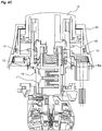
figures 3A et 3B représentent, vu suivant deux coupes transversales axiales, le dispositif d'arrêt d'urgence de l'invention en position de repos ; - Les
figures 4A à 4C illustrent, par des vues en coupe axiale transversale, le principe de fonctionnement du dispositif d'arrêt d'urgence de l'invention, respectivement en position de repos, en position actionnée et en position actionnée-relâchée.
- The
figure 1 represents, in perspective, the emergency stop device of the invention in the initial rest position; - The
figure 2 shows, exploded, the emergency stop device of the invention; - The
Figures 3A and 3B represent, seen according to two axial cross sections, the emergency stop device of the invention in the rest position; - The
Figures 4A to 4C illustrate, by transverse axial sectional views, the operating principle of the emergency stop device of the invention, respectively in the rest position, in the actuated position and in the actuated-released position.
De manière connue, un dispositif d'arrêt d'urgence 1 est destiné à la commande d'un circuit électrique et peut être actionné par un opérateur pour ouvrir le circuit électrique en cas d'urgence.In known manner, an
Le dispositif d'arrêt d'urgence 1 de l'invention pourra être monté à travers une ouverture de diamètre standard (par exemple diamètre 22mm ou 30mm) réalisée dans une paroi ou dans une boîte d'encastrement fixée sur la paroi ou encastrée dans la paroi. De manière classique, une bague de fixation 25 sera par exemple employée pour assurer la fixation du dispositif sur la paroi. On définit le côté avant de la paroi comme le côté duquel le bouton de commande est accessible et le côté arrière de la paroi comme le côté où est placé l'ensemble de contacts électriques.The
Dans la suite de la description et sur les dessins annexés, nous définissons un axe de commande (X) suivant lequel les parties mobiles du dispositif 1 sont actionnés en translation. Les termes "supérieur", "inférieur", 'haut" ou "bas" sont à comprendre en prenant comme référence l'axe de commande (X) selon une direction verticale.In the remainder of the description and the accompanying drawings, we define a control axis (X) according to which the moving parts of the
Dans la suite de la description, on définit trois positions ou états distincts du dispositif. Ces trois positions s'appliquent à tous les éléments mobiles du dispositif d'arrêt d'urgence décrit ci-dessous. Ces trois positions sont les suivantes :
- Position de repos dans laquelle les différents éléments mobiles sont à l'état repos, c'est-à-dire avant actionnement du dispositif ;
- Position actionnée obtenue après un actionnement du dispositif ; L'actionnement est alors réalisé jusqu'à ce que le bouton de commande arrive en butée ;
- Position actionnée-relâchée obtenue après actionnement du dispositif et relâchement du bouton de commande ; Pour sortir de cette position, le dispositif devra être déverrouillé.
- Rest position in which the various mobile elements are in the idle state, that is to say before actuation of the device;
- Actuated position obtained after an actuation of the device; The actuation is then carried out until the control button reaches the stop;
- Actuated-released position obtained after actuation of the device and release of the control button; To exit this position, the device must be unlocked.
Le dispositif d'arrêt d'urgence de l'invention comporte plusieurs ensembles fonctionnels :
- Un ensemble de commande ;
- Un ensemble d'actionnement ;
- Un ensemble de déverrouillage ;
- Un ensemble de contacts électriques.
- A command set;
- An actuation assembly;
- An unlocking assembly;
- A set of electrical contacts.
Le dispositif d'arrêt d'urgence de l'invention comporte un corps. On considérera ci-après que toutes les parties du dispositif qui sont fixes lors du fonctionnement du dispositif font partie du corps. Le corps comporte avantageusement un boîtier interne 14 sur lequel est notamment assemblé l'ensemble d'actionnement et un boîtier externe 13 assemblé sur le boîtier interne et sur lequel est notamment assemblé l'ensemble de déverrouillage. Le boîtier externe 13 présente par exemple une forme générale de couronne comprenant une base 130 et un capot 131. Ledit capot 131 comporte avantageusement une couronne 132 basse et une partie tubulaire 133 s'étendant au-dessus de la couronne 132. Le boîtier interne se présente pour sa part sous la forme d'un bloc indépendant venant s'insérer axialement dans l'espace axial ménagé au centre de la couronne.The emergency stop device of the invention comprises a body. It will be considered below that all the parts of the device which are fixed during operation of the device are part of the body. The body advantageously comprises an
Le boîtier interne 14 comporte une partie haute 140 évasée définissant une collerette et une partie basse 141, séparée entre elles par un épaulement. Il comporte également une ouverture axiale sur toute sa hauteur et un manchon interne 142 définissant une cuvette 143 avec sa collerette. Grâce au boîtier interne, l'ensemble d'actionnement comporte avantageusement une structure monobloc, c'est-à-dire en une seule pièce. L'ensemble d'actionnement est donc susceptible d'être facilement remplacé, sans avoir à toucher le reste du dispositif 1, notamment les ensembles logés dans le boîtier externe 13.The
Selon un aspect particulier de l'invention, après montage du dispositif sur une paroi, l'architecture du dispositif est réalisée de sorte que :
- Le boîtier externe 13 est situé du côté avant par rapport à la paroi ;
- La partie basse 141 du boîtier interne 14 est insérée à travers l'ouverture standard réalisée dans la paroi, de manière à ce que son épaulement vienne en appui contre la paroi, en périphérie de l'ouverture, du côté avant de la paroi ;
- La bague de fixation est positionnée sur la partie basse du boîtier interne pour verrouiller la fixation du dispositif du côté arrière de la paroi.
- The
outer casing 13 is located on the front side with respect to the wall; - The
lower part 141 of theinner casing 14 is inserted through the standard opening made in the wall, so that its shoulder bears against the wall, at the periphery of the opening, on the front side of the wall; - The fixing ring is positioned on the lower part of the inner casing to lock the attachment of the device to the rear side of the wall.
L'ensemble de commande du dispositif d'arrêt d'urgence comporte un bouton de commande 11, monté en coulissement dans la partie tubulaire 133 du boîtier externe 13 du corps, de manière à pouvoir être actionné en translation par rapport au corps du dispositif selon ledit axe de commande (X). Le bouton de commande 11 est initialement dans une position de repos dans laquelle le circuit électrique commandé est fermé. Par pression vers l'intérieur du dispositif, le bouton de commande 11 est coulissé dans la partie tubulaire 133 pour être amené dans une position actionnée dans laquelle il vient en butée contre le corps du dispositif, permettant alors d'ouvrir de manière positive le circuit électrique. Après actionnement, le bouton de commande 11 est relâché mais reste alors accroché dans une position dite actionnée-relâchée, dans laquelle le circuit électrique reste ouvert. Le circuit électrique reste ouvert jusqu'à ce que le dispositif soit déverrouillé.The control assembly of the emergency stop device comprises a
Le bouton de commande 11 comporte avantageusement une tête 111 sur laquelle une pression peut être appliquée pour actionner le dispositif et une queue 112 s'étendant dans une direction axiale vers l'intérieur du dispositif et destinée à coopérer avec l'ensemble d'actionnement du dispositif. La tête du dispositif comporte avantageusement une section de forme non circulaire, lui permettant de coopérer en rotation avec la bague de déverrouillage 20.The
En référence aux
Le poussoir d'actionnement 12 est monté coulissant dans la collerette du boîtier interne 14. Le poussoir d'actionnement 12 se présente sous la forme d'une pièce cylindrique comprenant un manchon interne 120 et un manchon externe 121 formant entre eux une cuvette 122. Le poussoir d'actionnement 12 comporte également une collerette 123 réalisée sur son manchon externe.The
L'ensemble d'actionnement comporte un ressort d'actionnement R1 venant prendre appui d'une part contre le fond de la cuvette 143 du boîtier interne et d'autre part contre la collerette 123 du poussoir d'actionnement 12, de sorte que le poussoir 12 d'actionnement soit monté sur ce ressort d'actionnement R1.The actuating assembly comprises an actuating spring R1 bearing on the one hand against the bottom of the
L'ensemble d'actionnement comporte également un poussoir de déclenchement 15. Ce poussoir de déclenchement 15 se présente sous la forme d'une douille qui est accrochée au poussoir d'actionnement 12 tout en conservant un degré de liberté en translation dans la direction axiale par rapport au poussoir d'actionnement 12 entre deux positions de butée. L'ensemble d'actionnement comporte un ressort de déclenchement R2 venant prendre appui d'une part au fond de la cuvette 122 du poussoir d'actionnement 12 et d'autre part dans le fond 150 de la douille formée par le poussoir de déclenchement 15.The actuating assembly also comprises a triggering
L'ensemble d'actionnement comporte également un organe de déclenchement 16 et un organe d'accrochage 17 par exemple composés chacun d'un doigt venant se loger dans un logement radial réalisé sur le poussoir de déclenchement 15. Chacun de ces deux organes est monté sur un ressort hélicoïdal R3, R4 distinct de manière à pouvoir se déplacer de manière radiale par rapport à l'axe de commande (X). L'organe de déclenchement 16 et l'organe d'accrochage 17 sont positionnés de manière à coopérer chacun avec le boîtier interne selon la position du poussoir de déclenchement 15. L'organe de déclenchement 16 et l'organe d'accrochage 17 sont susceptibles de se déplacer suivant deux plans parallèles distincts, perpendiculaires à l'axe de commande (X). Le plan de translation de l'organe de déclenchement 16 est situé au-dessus du plan de translation de l'organe d'accrochage 17. Sur la surface interne de son ouverture centrale, boîtier interne comporte des formes de cames destinées à être suivies par l'organe de déclenchement 16 et l'organe d'accrochage 17, permettant à chacun de ces organes de remplir leur fonction.The actuating assembly also comprises a triggering
L'organe de déclenchement 16 est en butée contre une butée 144 du boîtier interne pour verrouiller le déplacement du poussoir de déclenchement 15 vers le bas et le maintenir en position de repos jusqu'à ce qu'une énergie suffisante soit emmagasinée dans le ressort d'actionnement R1. Lorsque le bouton de commande 11 est suffisamment enfoncé, sous l'action d'une forme de came réalisée sur le corps, l'organe de déclenchement 16 s'escamote dans son logement, déverrouillant le poussoir de déclenchement 15. Sous l'action du ressort de déclenchement R2, le poussoir de déclenchement 15 est entraîné en translation vers le bas. Après déclenchement, par les liaisons mécaniques existant à la fois entre, d'une part, le poussoir de déclenchement 15 et le poussoir d'actionnement 12 et, d'autre part, entre le poussoir d'actionnement 12 et le bouton de commande 11, le bouton de commande 11 est maintenu en position actionnée-relâchée vers l'intérieur du corps. L'organe d'accrochage 17 coopère avec une butée 145 réalisée sur le boîtier interne pour permettre d'accrocher le poussoir de déclenchement 15 au corps lorsque le bouton de commande 11 est enfoncé dans sa position actionnée et ainsi de maintenir/verrouiller le poussoir d'actionnement 12 et le bouton de commande 11 dans la position actionnée-relâchée.The triggering
L'ensemble de contacts électriques comporte avantageusement au moins une unité de contact électrique 18, généralement au moins deux unités de contact électrique pour assurer une redondance lors de l'actionnement du dispositif. Chaque unité de contact électrique 18 comporte un jeu de contacts électriques normalement fermé (contacts NC pour "Normally Closed"). Chaque unité de contact 18 comporte par exemple un poussoir 180 solidaire d'un pont de contacts mobiles destiné à être actionné de manière axiale par la queue du poussoir de déclenchement. Les unités de contact sont par exemple fixées sur une embase 19 assemblée sur le corps du dispositif, plus précisément directement sur la partie basse 141 du boîtier interne. Ces caractéristiques étant classiques dans le domaine de la boutonnerie industrielle, elles ne sont pas décrites dans la présente demande de brevet.The set of electrical contacts advantageously comprises at least one
L'ensemble de déverrouillage comporte une bague de déverrouillage 20 distincte du bouton de commande 11, qui est montée mobile en rotation sur le boîtier externe 13 du corps, plus précisément sur la partie tubulaire 133 du capot du boîtier externe. La bague de déverrouillage 20 est agencée en périphérie du bouton de commande 11 et coopère en rotation avec le bouton de commande 11 pour le déverrouiller. Des moyens d'entraînement sont agencés entre la bague et le bouton de commande pour assurer l'entraînement du bouton de commande 11 par la bague de déverrouillage 20 lorsque la bague est actionnée en rotation. Ces moyens d'entraînement sont par exemple réalisés par la forme extérieure de la section du bouton de commande 11 et la forme interne de la section de la bague de déverrouillage 20. Sur les figures annexées, le bouton de commande présente une section sensiblement carrée (arrondie à ses sommets) et la bague présente une section dont la forme intérieure vient épouser le contour résultant de cette forme carrée.The unlocking assembly comprises an unlocking
Selon un aspect particulier de l'invention, en plus du ressort d'actionnement R1 et du ressort de déclenchement R2, l'ensemble de déverrouillage comporte un ressort R5 spécifique agencé pour entraîner le bouton de commande vers sa position initiale de repos. Ce ressort de déverrouillage R5 est avantageusement logé dans le boîtier externe 13 du corps et est guidé par la paroi formée de la collerette située en partie haute du boîtier interne. Il présente une extrémité attachée au bouton de commande 11 et une autre extrémité attachée au fond du boîtier externe 13. Il est avantageusement précontraint entre ses deux extrémités, en translation dans la direction axiale et en torsion autour de cette direction axiale de manière à assurer également le retour de la bague vers sa position initiale après rotation.According to a particular aspect of the invention, in addition to the actuating spring R1 and the trigger spring R2, the unlocking assembly comprises a specific spring R5 arranged to drive the control button to its initial rest position. This unlocking spring R5 is advantageously housed in the
Lors de la rotation de la bague de déverrouillage 20, celle-ci entraîne en rotation le bouton de commande 11 qui entraîne en rotation le poussoir d'actionnement 12 puis le poussoir de déclenchement. La rotation du poussoir de déclenchement 15 libère l'organe d'accrochage 17 de la butée réalisée sur le corps et permet de libérer le bouton de commande 11, qui, sous l'action du ressort de déverrouillage R5, est alors ramené vers sa position de repos. Le ressort de déverrouillage R5 étant précontraint en torsion et en compression, le retour du bouton de commande 11 vers sa position initiale suit une trajectoire de translation combinée à une rotation.During rotation of the unlocking
L'emploi d'une bague de déverrouillage 20 distincte du bouton de commande 11 permet de pouvoir proposer un dispositif présentant une architecture particulièrement compacte.The use of an unlocking
Selon un autre aspect particulièrement avantageux de l'invention, on comprend que les trois ressorts R1, R2, R5 sont montés dans des espaces agencés de manière concentrique autour de l'axe de commande (X). Le ressort R2 est situé au plus près de l'axe de commande, le ressort R1 est monté en périphérie du ressort R2 et le ressort R5 est monté en périphérie du ressort R1. Cet agencement permet notamment de gagner en compacité dans le sens de la hauteur.According to another particularly advantageous aspect of the invention, it is understood that the three springs R1, R2, R5 are mounted in spaces arranged concentrically around the control axis (X). The spring R2 is located closer to the control axis, the spring R1 is mounted at the periphery of the spring R2 and the spring R5 is mounted at the periphery of the spring R1. This arrangement allows in particular to gain compactness in the direction of the height.
Bien entendu, les deux ressorts R1 et R2 devront être choisis et adaptés pour assurer un déclenchement du dispositif lorsqu'une certaine pression est exercée sur le bouton de commande. Le ressort R5 sera pour sa part choisi pour assurer le retour du bouton de commande en position initiale, de manière indépendante du choix des deux ressorts R1 et R2. La fonction de déverrouillage sera donc totalement indépendante de la fonction de déclenchement du dispositif.Of course, the two springs R1 and R2 will have to be chosen and adapted to trigger the device when a certain pressure is exerted on the control button. The spring R5 will be selected for the return of the control knob to the initial position, independently of the choice of the two springs R1 and R2. The unlocking function will therefore be totally independent of the triggering function of the device.
Le dispositif d'arrêt d'urgence comporte avantageusement un ensemble lumineux complètement intégré au dispositif, assemblé sur un circuit imprimé 21 logé dans le boîtier externe 13. Cet ensemble lumineux est destiné à assurer une fonction de signalisation lumineuse du dispositif d'arrêt d'urgence. Cet ensemble lumineux comporte par exemple une ou plusieurs diodes électroluminescentes soudées sur le circuit imprimé 21 et connectées à des blocs d'alimentation. L'ensemble lumineux est par exemple commandé pour allumer en jaune ou en rouge le dispositif d'arrêt d'urgence selon l'état de fonctionnement de ce dernier. Le capot 131 du boîtier externe 13 peut présenter une couronne transparente 132 laissant passer la lumière des diodes vers l'extérieur. Cet ensemble lumineux étant logé dans le boîtier externe, son fonctionnement ne vient pas perturber le fonctionnement de l'ensemble d'actionnement. Les blocs d'alimentation des diodes électroluminescentes sont par exemple placés du côté arrière de la paroi et sont reliés aux diodes par des fils passant par exemple par un trou adjacent à l'ouverture de fixation du dispositif ou à travers l'ouverture de fixation du dispositif 1 si celle-ci est de taille adaptée au passage des fils d'alimentation.The emergency stop device advantageously comprises a light assembly completely integrated in the device, assembled on a printed
Selon un aspect particulièrement avantageux de l'invention, la séparation bien distincte de la fonction d'actionnement et de la fonction de déverrouillage permet de proposer une solution d'étanchéité particulièrement efficace. Le boîtier externe 13 comporte une première solution d'étanchéité et le boîtier interne 14 comporte une deuxième solution d'étanchéité.According to a particularly advantageous aspect of the invention, the separation quite distinct from the actuating function and the unlocking function makes it possible to propose a particularly effective sealing solution. The
La première solution d'étanchéité comporte notamment un joint à lèvre 22 agencé dans une gorge 110 réalisée sur le flanc latéral du bouton de commande 11. Ce joint à lèvre est destiné à venir frotter contre la paroi interne de la partie tubulaire 133 du capot 131 du boîtier externe 13. Il permet ainsi d'assurer l'étanchéité dans le coulissement du bouton de commande. La présence du ressort de déverrouillage R5 spécifique permet par ailleurs d'assurer le retour du bouton de commande vers sa position de repos, malgré le frottement du joint à lèvre lors du fonctionnement.The first sealing solution comprises in particular a
La deuxième solution d'étanchéité comporte notamment un joint à lèvre 23 agencé entre le poussoir d'actionnement 12 et le boîtier interne 14. Ce joint à lèvre 23 est positionné en appui contre la collerette 123 du poussoir d'actionnement 12, sur la face d'appui opposée à celle du ressort d'actionnement. Ce joint à lèvre permet de protéger le volume délimité par le boîtier interne 14 du dispositif de toute intrusion de poussières ou de liquide, assurant un fonctionnement toujours fiable de l'ensemble d'actionnement.The second sealing solution comprises in particular a
Un joint 24 supplémentaire de forme annulaire est également positionné sous la base 130 du boîtier externe.An additional ring-shaped
En référence aux figures annexées, le fonctionnement du dispositif d'arrêt d'urgence de l'invention suit les différentes phases successives ci-dessous :With reference to the appended figures, the operation of the emergency stop device of the invention follows the different successive phases below:
- Le dispositif est en position de repos ;The device is in the rest position;
-
Le bouton de commande 11 est en en position haute ;The
control knob 11 is in the high position; - Le dispositif est par exemple éclairé dans une première couleur indiquant son état de fonctionnement.The device is for example illuminated in a first color indicating its operating state.
-
Le bouton de commande 11 est appuyé jusqu'à la butée dans la direction axiale (X) ;The
control knob 11 is pressed to the stop in the axial direction (X); -
Le poussoir d'actionnement 12, solidaire du bouton de commande 11, est entraîné en translation suivant la direction axiale (X) ;The
actuating pusher 12, integral with thecontrol knob 11, is driven in translation along the axial direction (X); -
La compression du ressort d'actionnement R1 est suffisante pour entraîner un déclenchement du dispositif 1 ;The compression of the actuating spring R1 is sufficient to cause triggering of the
device 1; -
L'organe de déclenchement 16 s'escamote dans son logement ;The
trigger member 16 retracts into its housing; -
Le poussoir de déclenchement 15 est libéré de sa butée formée par l'organe de déclenchement 16 contre le corps ;The triggering
pusher 15 is released from its stop formed by thetrigger member 16 against the body; -
Le ressort de déclenchement R2 se détend entre le poussoir d'actionnement 12 et le poussoir de déclenchement 15 ;The trigger spring R2 expands between the
actuating pusher 12 and the triggeringpusher 15; -
Le poussoir de déclenchement 15 est entraîné en translation axiale par le ressort de déclenchement R2 ;The triggering
pusher 15 is driven in axial translation by the triggering spring R2; -
En bout de course, le poussoir de déclenchement 15 agit sur l'ensemble de contact 18.At the end of the stroke, the triggering
pushbutton 15 acts on thecontact assembly 18.
-
Le bouton de commande 11 est en butée ;The
control button 11 is in abutment; -
Le poussoir de déclenchement 15 est en position basse ;The triggering
pusher 15 is in the low position; -
L'organe d'accrochage 17 est libéré de son logement sous l'action de son ressort ;The
attachment member 17 is released from its housing under the action of its spring; -
Le ressort d'actionnement R1 est comprimé entre le corps et le poussoir d'actionnement 12 ;The actuating spring R1 is compressed between the body and the
actuating pusher 12; -
Le ressort de déclenchement R2 est comprimé entre le poussoir d'actionnement 12 et le poussoir de déclenchement 15 ;The trigger spring R2 is compressed between the
actuating pusher 12 and the triggeringpusher 15; - Le dispositif est par exemple éclairé dans une deuxième couleur indiquant son nouvel état de fonctionnement.The device is for example illuminated in a second color indicating its new operating state.
-
Le bouton de commande 11 est relâché ;The
control button 11 is released; -
L'organe d'accrochage 17 vient coopérer avec la butée 145 du corps du dispositif ;The hooking
member 17 cooperates with thestop 145 of the body of the device; -
Le poussoir de déclenchement 15 est maintenu en position basse par l'organe d'accrochage 17 ;The triggering
pusher 15 is held in the lower position by thefastening member 17; -
Le poussoir d'actionnement 12 et le bouton de commande 11, solidaires du poussoir de déclenchement 15, sont retenus en position actionnée relâchée ;The
actuating pusher 12 and thecontrol knob 11, integral with the triggeringpusher 15, are retained in the released actuated position; - Le ressort d'actionnement R1 reste contraint ;The actuating spring R1 remains constrained;
- Le ressort de déclenchement R2 est relâché ;The trigger spring R2 is released;
- Le dispositif reste éclairé dans la deuxième couleur indiquant son état de fonctionnement.The device remains illuminated in the second color indicating its operating status.
-
La bague de déverrouillage 20 est actionnée en rotation ;The unlocking
ring 20 is actuated in rotation; -
Lors de sa rotation, la bague de déverrouillage 20 entraîne le bouton de commande 11 ;During its rotation, the unlocking
ring 20 drives thecontrol knob 11; -
Lors de sa rotation, le bouton de commande 11 entraîne en rotation le poussoir d'actionnement 12 et le poussoir de déclenchement 15 ;During its rotation, the
control knob 11 rotates theactuating pusher 12 and the triggeringpusher 15; -
La rotation du poussoir de déclenchement 15 entraîne le retour de l'organe d'accrochage 17 dans son logement, par le suivi de formes de cames réalisées sur le corps ;The rotation of the triggering
pusher 15 causes the return of thefastening member 17 in its housing, by the follow-up of cam shapes made on the body; -
Le poussoir de déclenchement 15 est libéré de sa position accrochée et libère ainsi en translation le poussoir d'actionnement 12 et le bouton de commande 11 ;The triggering
pusher 15 is released from its hooked position and thus releases in translation theactuating pusher 12 and thecontrol knob 11; -
Le bouton de commande 11, à nouveau libre en translation, est ramené en position de repos par le ressort de déverrouillage R5 ;The
control button 11, again free in translation, is returned to the rest position by the unlocking spring R5; - Le ressort de déverrouillage se détend en torsion et en translation entraînant le bouton de commande dans le même mouvement de torsion/translation ;The unlocking spring expands in torsion and in translation driving the control button in the same torsion / translation movement;
- Le dispositif est revenu dans sa position de repos initiale ;The device has returned to its initial resting position;
- Le dispositif est à nouveau éclairé dans la première couleur.The device is illuminated again in the first color.
On comprend de la description ci-dessus que le dispositif de l'invention présente certains avantages, parmi lesquels :
- Une totale indépendance entre la fonction d'actionnement/déclenchement et la fonction de déverrouillage, grâce notamment à l'utilisation d'un ressort R5 distinct dédié au déverrouillage ;
- La possibilité de régler la force des différents ressorts de manière indépendante pour la fonction d'actionnement/déclenchement (ressorts R1 et R2) et la pour la fonction de déverrouillage (R5) ;
- L'indépendance entre la fonction d'actionnement/déclenchement et la fonction de déverrouillage permet de proposer une architecture à deux boîtiers bien distincts, le boîtier interne et le boîtier externe ;
- L'indépendance entre la fonction d'actionnement/déclenchement et la fonction de déverrouillage permet de proposer une architecture dans laquelle les solutions d'étanchéité employées sont bien distinctes, permettant notamment de protéger la fonction d'actionnement/déclenchement par rapport à la fonction de déverrouillage ;
- La possibilité de proposer de manière simple et fiable un dispositif doté d'une fonction de signalisation lumineuse ;
- L'architecture du dispositif permet également de remplir la fonction dite de non-entrave, c'est-à-dire qu'elle évite toute entrave au bon fonctionnement du dispositif par des dispositifs positionnés sur la même paroi.
- Total independence between the actuation / release function and the unlocking function, thanks to the use of a separate R5 spring dedicated to unlocking;
- The possibility to adjust the force of the different springs independently for the actuation / release function (springs R1 and R2) and the for the unlock function (R5);
- The independence between the actuation / release function and the unlocking function makes it possible to propose an architecture with two distinct housings, the inner casing and the outer casing;
- The independence between the actuation / release function and the unlocking function makes it possible to propose an architecture in which the sealing solutions used are distinct, notably making it possible to protect the actuation / release function with respect to the function of the actuator. unlocking;
- The possibility of providing a simple and reliable device with a function of light signaling;
- The architecture of the device also makes it possible to fulfill the so-called non-interference function, that is to say it avoids any obstacle to the proper functioning of the device by devices positioned on the same wall.
Claims (12)
Applications Claiming Priority (1)
| Application Number | Priority Date | Filing Date | Title |
|---|---|---|---|
| FR1753832A FR3066042A1 (en) | 2017-05-02 | 2017-05-02 | EMERGENCY STOP DEVICE |
Publications (2)
| Publication Number | Publication Date |
|---|---|
| EP3399532A1 true EP3399532A1 (en) | 2018-11-07 |
| EP3399532B1 EP3399532B1 (en) | 2019-07-24 |
Family
ID=59409468
Family Applications (1)
| Application Number | Title | Priority Date | Filing Date |
|---|---|---|---|
| EP18166986.2A Active EP3399532B1 (en) | 2017-05-02 | 2018-04-12 | Emergency stop device |
Country Status (5)
| Country | Link |
|---|---|
| US (1) | US10475597B2 (en) |
| EP (1) | EP3399532B1 (en) |
| CN (1) | CN108807023B (en) |
| ES (1) | ES2747832T3 (en) |
| FR (1) | FR3066042A1 (en) |
Families Citing this family (5)
| Publication number | Priority date | Publication date | Assignee | Title |
|---|---|---|---|---|
| US9684329B2 (en) * | 2014-06-22 | 2017-06-20 | Trevor Lawson | Automatic locking knob assemblies and methods of use |
| USD887996S1 (en) * | 2018-03-19 | 2020-06-23 | Schneider Electric Industries Sas | Emergency stop button |
| DK3877999T3 (en) * | 2018-11-09 | 2023-04-11 | Linak As | Emergency stop |
| FR3121521B1 (en) * | 2021-04-06 | 2023-02-24 | C&K Components Sas | ELECTRIC SWITCH |
| US11960315B1 (en) | 2023-10-25 | 2024-04-16 | Rangesafe, Llc | Automatically locking, releasable, safety knob assembly systems |
Citations (2)
| Publication number | Priority date | Publication date | Assignee | Title |
|---|---|---|---|---|
| FR2792453A1 (en) * | 1999-04-16 | 2000-10-20 | Schneider Electric Sa | PUSH BUTTON TYPE SWITCH FOR EMERGENCY STOP |
| EP2700080A1 (en) * | 2011-04-18 | 2014-02-26 | Schneider Electric Industries SAS | Emergency stopping device |
Family Cites Families (7)
| Publication number | Priority date | Publication date | Assignee | Title |
|---|---|---|---|---|
| US6376785B1 (en) * | 1999-09-27 | 2002-04-23 | Rockwell Automation Technologies, Inc. | Removable latch assembly for an electrical switch |
| US6198058B1 (en) * | 1999-09-27 | 2001-03-06 | Rockwell Technologies, Llc | Switch contact mechanism |
| JP3908134B2 (en) * | 2002-09-09 | 2007-04-25 | Idec株式会社 | Switch device |
| JP5095691B2 (en) * | 2008-10-27 | 2012-12-12 | 富士電機機器制御株式会社 | Push-button switch |
| CN107248460B (en) * | 2013-02-04 | 2019-09-24 | 富士电机机器制御株式会社 | Switching device |
| EP3011576B8 (en) * | 2013-06-20 | 2018-04-11 | Eaton Intelligent Power Limited | Emergency push switch with correct assembly reporting means |
| CN203415438U (en) * | 2013-09-16 | 2014-01-29 | 乐清市信达利实业有限公司 | Emergency stop button switch |
-
2017
- 2017-05-02 FR FR1753832A patent/FR3066042A1/en active Pending
-
2018
- 2018-04-12 ES ES18166986T patent/ES2747832T3/en active Active
- 2018-04-12 EP EP18166986.2A patent/EP3399532B1/en active Active
- 2018-04-20 US US15/957,978 patent/US10475597B2/en active Active
- 2018-05-02 CN CN201810409531.4A patent/CN108807023B/en active Active
Patent Citations (2)
| Publication number | Priority date | Publication date | Assignee | Title |
|---|---|---|---|---|
| FR2792453A1 (en) * | 1999-04-16 | 2000-10-20 | Schneider Electric Sa | PUSH BUTTON TYPE SWITCH FOR EMERGENCY STOP |
| EP2700080A1 (en) * | 2011-04-18 | 2014-02-26 | Schneider Electric Industries SAS | Emergency stopping device |
Also Published As
| Publication number | Publication date |
|---|---|
| US10475597B2 (en) | 2019-11-12 |
| FR3066042A1 (en) | 2018-11-09 |
| ES2747832T3 (en) | 2020-03-11 |
| CN108807023A (en) | 2018-11-13 |
| US20180323018A1 (en) | 2018-11-08 |
| EP3399532B1 (en) | 2019-07-24 |
| CN108807023B (en) | 2022-05-27 |
Similar Documents
| Publication | Publication Date | Title |
|---|---|---|
| EP3399532B1 (en) | Emergency stop device | |
| EP2700080B1 (en) | Emergency stopping device | |
| EP1747567B1 (en) | Rotary knob for electrical system | |
| EP1851403B1 (en) | Turning knob with lock | |
| EP2754162B1 (en) | Emergency stop device adaptable for a man-machine dialog system | |
| WO2005038538A1 (en) | Wristwatch push-piece winding button control device | |
| EP2332158B1 (en) | Emergency stop device | |
| EP2564408B1 (en) | Emergency stop device | |
| FR2606450A1 (en) | ELECTRICALLY ACTUATED LOCK FOR MOUNTING ON MOTOR VEHICLES | |
| EP3651173B1 (en) | Switching assembly with secure attaching solution for emergency stop device | |
| EP1103991A2 (en) | Solenoid valve with manually operated pushrod | |
| FR2808552A1 (en) | Lock with mechanical and electrical release, uses spring-loaded pin engaging in shallow recess in lock rotor to stop operation of lock and has a rotating cam under pin to allow it to move clear when correct key is detected | |
| CH666369A5 (en) | EMERGENCY SWITCHING APPARATUS CONTROLLING AN ELECTRICAL SWITCH. | |
| WO2011032817A1 (en) | Emergency stoppage device | |
| EP1741364A1 (en) | Lipstick holder assembly and closing cap connected therewith | |
| EP2564409B1 (en) | Emergency stop device with secure mounted switching assemblies | |
| WO2021122040A1 (en) | Mechanism for an electrical switch, electrical assembly and electrical switch thereof | |
| FR2818792A3 (en) | Electrical switch for brake lights includes self-adjusting mechanism with joint having elastically deformable teeth | |
| EP0880155B1 (en) | Electric lock controlled by a switch which can be inhibited | |
| FR2984947A3 (en) | Safety hinge for connecting protective cover to frame of industrial machine, has rotor fastened on leg and attached to carriage, where carriage is connected with drive element that is provided on switch housing | |
| CH704691B1 (en) | Pushbutton improved guidance. | |
| EP1845546A2 (en) | Bistable manoeuvring device of a mobile shaft and battery cutout comprising such a device | |
| CH687284B5 (en) | Declic push for a timepiece. |
Legal Events
| Date | Code | Title | Description |
|---|---|---|---|
| PUAI | Public reference made under article 153(3) epc to a published international application that has entered the european phase |
Free format text: ORIGINAL CODE: 0009012 |
|
| STAA | Information on the status of an ep patent application or granted ep patent |
Free format text: STATUS: THE APPLICATION HAS BEEN PUBLISHED |
|
| AK | Designated contracting states |
Kind code of ref document: A1 Designated state(s): AL AT BE BG CH CY CZ DE DK EE ES FI FR GB GR HR HU IE IS IT LI LT LU LV MC MK MT NL NO PL PT RO RS SE SI SK SM TR |
|
| AX | Request for extension of the european patent |
Extension state: BA ME |
|
| STAA | Information on the status of an ep patent application or granted ep patent |
Free format text: STATUS: REQUEST FOR EXAMINATION WAS MADE |
|
| 17P | Request for examination filed |
Effective date: 20190311 |
|
| RBV | Designated contracting states (corrected) |
Designated state(s): AL AT BE BG CH CY CZ DE DK EE ES FI FR GB GR HR HU IE IS IT LI LT LU LV MC MK MT NL NO PL PT RO RS SE SI SK SM TR |
|
| GRAP | Despatch of communication of intention to grant a patent |
Free format text: ORIGINAL CODE: EPIDOSNIGR1 |
|
| STAA | Information on the status of an ep patent application or granted ep patent |
Free format text: STATUS: GRANT OF PATENT IS INTENDED |
|
| INTG | Intention to grant announced |
Effective date: 20190514 |
|
| GRAS | Grant fee paid |
Free format text: ORIGINAL CODE: EPIDOSNIGR3 |
|
| GRAA | (expected) grant |
Free format text: ORIGINAL CODE: 0009210 |
|
| STAA | Information on the status of an ep patent application or granted ep patent |
Free format text: STATUS: THE PATENT HAS BEEN GRANTED |
|
| AK | Designated contracting states |
Kind code of ref document: B1 Designated state(s): AL AT BE BG CH CY CZ DE DK EE ES FI FR GB GR HR HU IE IS IT LI LT LU LV MC MK MT NL NO PL PT RO RS SE SI SK SM TR |
|
| REG | Reference to a national code |
Ref country code: GB Ref legal event code: FG4D Free format text: NOT ENGLISH |
|
| REG | Reference to a national code |
Ref country code: CH Ref legal event code: EP |
|
| REG | Reference to a national code |
Ref country code: DE Ref legal event code: R096 Ref document number: 602018000294 Country of ref document: DE |
|
| REG | Reference to a national code |
Ref country code: AT Ref legal event code: REF Ref document number: 1159193 Country of ref document: AT Kind code of ref document: T Effective date: 20190815 |
|
| REG | Reference to a national code |
Ref country code: IE Ref legal event code: FG4D Free format text: LANGUAGE OF EP DOCUMENT: FRENCH |
|
| REG | Reference to a national code |
Ref country code: NL Ref legal event code: MP Effective date: 20190724 |
|
| REG | Reference to a national code |
Ref country code: LT Ref legal event code: MG4D |
|
| REG | Reference to a national code |
Ref country code: AT Ref legal event code: MK05 Ref document number: 1159193 Country of ref document: AT Kind code of ref document: T Effective date: 20190724 |
|
| PG25 | Lapsed in a contracting state [announced via postgrant information from national office to epo] |
Ref country code: FI Free format text: LAPSE BECAUSE OF FAILURE TO SUBMIT A TRANSLATION OF THE DESCRIPTION OR TO PAY THE FEE WITHIN THE PRESCRIBED TIME-LIMIT Effective date: 20190724 Ref country code: NO Free format text: LAPSE BECAUSE OF FAILURE TO SUBMIT A TRANSLATION OF THE DESCRIPTION OR TO PAY THE FEE WITHIN THE PRESCRIBED TIME-LIMIT Effective date: 20191024 Ref country code: PT Free format text: LAPSE BECAUSE OF FAILURE TO SUBMIT A TRANSLATION OF THE DESCRIPTION OR TO PAY THE FEE WITHIN THE PRESCRIBED TIME-LIMIT Effective date: 20191125 Ref country code: HR Free format text: LAPSE BECAUSE OF FAILURE TO SUBMIT A TRANSLATION OF THE DESCRIPTION OR TO PAY THE FEE WITHIN THE PRESCRIBED TIME-LIMIT Effective date: 20190724 Ref country code: NL Free format text: LAPSE BECAUSE OF FAILURE TO SUBMIT A TRANSLATION OF THE DESCRIPTION OR TO PAY THE FEE WITHIN THE PRESCRIBED TIME-LIMIT Effective date: 20190724 Ref country code: AT Free format text: LAPSE BECAUSE OF FAILURE TO SUBMIT A TRANSLATION OF THE DESCRIPTION OR TO PAY THE FEE WITHIN THE PRESCRIBED TIME-LIMIT Effective date: 20190724 Ref country code: BG Free format text: LAPSE BECAUSE OF FAILURE TO SUBMIT A TRANSLATION OF THE DESCRIPTION OR TO PAY THE FEE WITHIN THE PRESCRIBED TIME-LIMIT Effective date: 20191024 Ref country code: SE Free format text: LAPSE BECAUSE OF FAILURE TO SUBMIT A TRANSLATION OF THE DESCRIPTION OR TO PAY THE FEE WITHIN THE PRESCRIBED TIME-LIMIT Effective date: 20190724 Ref country code: LT Free format text: LAPSE BECAUSE OF FAILURE TO SUBMIT A TRANSLATION OF THE DESCRIPTION OR TO PAY THE FEE WITHIN THE PRESCRIBED TIME-LIMIT Effective date: 20190724 |
|
| PG25 | Lapsed in a contracting state [announced via postgrant information from national office to epo] |
Ref country code: RS Free format text: LAPSE BECAUSE OF FAILURE TO SUBMIT A TRANSLATION OF THE DESCRIPTION OR TO PAY THE FEE WITHIN THE PRESCRIBED TIME-LIMIT Effective date: 20190724 Ref country code: GR Free format text: LAPSE BECAUSE OF FAILURE TO SUBMIT A TRANSLATION OF THE DESCRIPTION OR TO PAY THE FEE WITHIN THE PRESCRIBED TIME-LIMIT Effective date: 20191025 Ref country code: IS Free format text: LAPSE BECAUSE OF FAILURE TO SUBMIT A TRANSLATION OF THE DESCRIPTION OR TO PAY THE FEE WITHIN THE PRESCRIBED TIME-LIMIT Effective date: 20191124 Ref country code: LV Free format text: LAPSE BECAUSE OF FAILURE TO SUBMIT A TRANSLATION OF THE DESCRIPTION OR TO PAY THE FEE WITHIN THE PRESCRIBED TIME-LIMIT Effective date: 20190724 Ref country code: AL Free format text: LAPSE BECAUSE OF FAILURE TO SUBMIT A TRANSLATION OF THE DESCRIPTION OR TO PAY THE FEE WITHIN THE PRESCRIBED TIME-LIMIT Effective date: 20190724 |
|
| REG | Reference to a national code |
Ref country code: ES Ref legal event code: FG2A Ref document number: 2747832 Country of ref document: ES Kind code of ref document: T3 Effective date: 20200311 |
|
| PG25 | Lapsed in a contracting state [announced via postgrant information from national office to epo] |
Ref country code: TR Free format text: LAPSE BECAUSE OF FAILURE TO SUBMIT A TRANSLATION OF THE DESCRIPTION OR TO PAY THE FEE WITHIN THE PRESCRIBED TIME-LIMIT Effective date: 20190724 |
|
| PG25 | Lapsed in a contracting state [announced via postgrant information from national office to epo] |
Ref country code: RO Free format text: LAPSE BECAUSE OF FAILURE TO SUBMIT A TRANSLATION OF THE DESCRIPTION OR TO PAY THE FEE WITHIN THE PRESCRIBED TIME-LIMIT Effective date: 20190724 Ref country code: PL Free format text: LAPSE BECAUSE OF FAILURE TO SUBMIT A TRANSLATION OF THE DESCRIPTION OR TO PAY THE FEE WITHIN THE PRESCRIBED TIME-LIMIT Effective date: 20190724 Ref country code: DK Free format text: LAPSE BECAUSE OF FAILURE TO SUBMIT A TRANSLATION OF THE DESCRIPTION OR TO PAY THE FEE WITHIN THE PRESCRIBED TIME-LIMIT Effective date: 20190724 Ref country code: EE Free format text: LAPSE BECAUSE OF FAILURE TO SUBMIT A TRANSLATION OF THE DESCRIPTION OR TO PAY THE FEE WITHIN THE PRESCRIBED TIME-LIMIT Effective date: 20190724 |
|
| PG25 | Lapsed in a contracting state [announced via postgrant information from national office to epo] |
Ref country code: IS Free format text: LAPSE BECAUSE OF FAILURE TO SUBMIT A TRANSLATION OF THE DESCRIPTION OR TO PAY THE FEE WITHIN THE PRESCRIBED TIME-LIMIT Effective date: 20200224 Ref country code: CZ Free format text: LAPSE BECAUSE OF FAILURE TO SUBMIT A TRANSLATION OF THE DESCRIPTION OR TO PAY THE FEE WITHIN THE PRESCRIBED TIME-LIMIT Effective date: 20190724 Ref country code: SM Free format text: LAPSE BECAUSE OF FAILURE TO SUBMIT A TRANSLATION OF THE DESCRIPTION OR TO PAY THE FEE WITHIN THE PRESCRIBED TIME-LIMIT Effective date: 20190724 Ref country code: SK Free format text: LAPSE BECAUSE OF FAILURE TO SUBMIT A TRANSLATION OF THE DESCRIPTION OR TO PAY THE FEE WITHIN THE PRESCRIBED TIME-LIMIT Effective date: 20190724 |
|
| REG | Reference to a national code |
Ref country code: DE Ref legal event code: R097 Ref document number: 602018000294 Country of ref document: DE |
|
| PLBE | No opposition filed within time limit |
Free format text: ORIGINAL CODE: 0009261 |
|
| STAA | Information on the status of an ep patent application or granted ep patent |
Free format text: STATUS: NO OPPOSITION FILED WITHIN TIME LIMIT |
|
| PG2D | Information on lapse in contracting state deleted |
Ref country code: IS |
|
| 26N | No opposition filed |
Effective date: 20200603 |
|
| PG25 | Lapsed in a contracting state [announced via postgrant information from national office to epo] |
Ref country code: MC Free format text: LAPSE BECAUSE OF FAILURE TO SUBMIT A TRANSLATION OF THE DESCRIPTION OR TO PAY THE FEE WITHIN THE PRESCRIBED TIME-LIMIT Effective date: 20190724 |
|
| PG25 | Lapsed in a contracting state [announced via postgrant information from national office to epo] |
Ref country code: LU Free format text: LAPSE BECAUSE OF NON-PAYMENT OF DUE FEES Effective date: 20200412 |
|
| REG | Reference to a national code |
Ref country code: BE Ref legal event code: MM Effective date: 20200430 |
|
| PG25 | Lapsed in a contracting state [announced via postgrant information from national office to epo] |
Ref country code: BE Free format text: LAPSE BECAUSE OF NON-PAYMENT OF DUE FEES Effective date: 20200430 |
|
| PG25 | Lapsed in a contracting state [announced via postgrant information from national office to epo] |
Ref country code: IE Free format text: LAPSE BECAUSE OF NON-PAYMENT OF DUE FEES Effective date: 20200412 |
|
| PG25 | Lapsed in a contracting state [announced via postgrant information from national office to epo] |
Ref country code: MT Free format text: LAPSE BECAUSE OF FAILURE TO SUBMIT A TRANSLATION OF THE DESCRIPTION OR TO PAY THE FEE WITHIN THE PRESCRIBED TIME-LIMIT Effective date: 20190724 Ref country code: CY Free format text: LAPSE BECAUSE OF FAILURE TO SUBMIT A TRANSLATION OF THE DESCRIPTION OR TO PAY THE FEE WITHIN THE PRESCRIBED TIME-LIMIT Effective date: 20190724 |
|
| PG25 | Lapsed in a contracting state [announced via postgrant information from national office to epo] |
Ref country code: MK Free format text: LAPSE BECAUSE OF FAILURE TO SUBMIT A TRANSLATION OF THE DESCRIPTION OR TO PAY THE FEE WITHIN THE PRESCRIBED TIME-LIMIT Effective date: 20190724 |
|
| PGFP | Annual fee paid to national office [announced via postgrant information from national office to epo] |
Ref country code: IT Payment date: 20230421 Year of fee payment: 6 Ref country code: FR Payment date: 20230421 Year of fee payment: 6 Ref country code: ES Payment date: 20230515 Year of fee payment: 6 Ref country code: DE Payment date: 20230427 Year of fee payment: 6 Ref country code: CH Payment date: 20230502 Year of fee payment: 6 |
|
| PG25 | Lapsed in a contracting state [announced via postgrant information from national office to epo] |
Ref country code: SI Free format text: LAPSE BECAUSE OF FAILURE TO SUBMIT A TRANSLATION OF THE DESCRIPTION OR TO PAY THE FEE WITHIN THE PRESCRIBED TIME-LIMIT Effective date: 20190724 |
|
| PGFP | Annual fee paid to national office [announced via postgrant information from national office to epo] |
Ref country code: GB Payment date: 20230418 Year of fee payment: 6 |