EP3399219B1 - Relief valve - Google Patents
Relief valve Download PDFInfo
- Publication number
- EP3399219B1 EP3399219B1 EP16881840.9A EP16881840A EP3399219B1 EP 3399219 B1 EP3399219 B1 EP 3399219B1 EP 16881840 A EP16881840 A EP 16881840A EP 3399219 B1 EP3399219 B1 EP 3399219B1
- Authority
- EP
- European Patent Office
- Prior art keywords
- valve
- pressure
- valve body
- gas
- relief valve
- Prior art date
- Legal status (The legal status is an assumption and is not a legal conclusion. Google has not performed a legal analysis and makes no representation as to the accuracy of the status listed.)
- Active
Links
- 230000002093 peripheral effect Effects 0.000 claims description 83
- 230000029058 respiratory gaseous exchange Effects 0.000 claims description 21
- 230000001105 regulatory effect Effects 0.000 claims description 14
- 239000000463 material Substances 0.000 claims description 6
- 206010002091 Anaesthesia Diseases 0.000 claims description 4
- 230000037005 anaesthesia Effects 0.000 claims description 4
- 238000004891 communication Methods 0.000 claims description 2
- 239000007789 gas Substances 0.000 description 81
- 238000000746 purification Methods 0.000 description 16
- 238000005273 aeration Methods 0.000 description 15
- 210000004072 lung Anatomy 0.000 description 13
- 230000003444 anaesthetic effect Effects 0.000 description 8
- 230000009189 diving Effects 0.000 description 8
- 238000004519 manufacturing process Methods 0.000 description 8
- 210000003811 finger Anatomy 0.000 description 6
- 239000011347 resin Substances 0.000 description 6
- 229920005989 resin Polymers 0.000 description 6
- 230000002159 abnormal effect Effects 0.000 description 5
- XLYOFNOQVPJJNP-UHFFFAOYSA-N water Substances O XLYOFNOQVPJJNP-UHFFFAOYSA-N 0.000 description 5
- 230000003187 abdominal effect Effects 0.000 description 4
- 230000005611 electricity Effects 0.000 description 4
- 210000003141 lower extremity Anatomy 0.000 description 4
- 238000000465 moulding Methods 0.000 description 4
- 238000005192 partition Methods 0.000 description 4
- 229920003023 plastic Polymers 0.000 description 4
- 239000004033 plastic Substances 0.000 description 4
- 230000002265 prevention Effects 0.000 description 4
- 238000007639 printing Methods 0.000 description 4
- 230000002040 relaxant effect Effects 0.000 description 4
- 210000001364 upper extremity Anatomy 0.000 description 4
- MYMOFIZGZYHOMD-UHFFFAOYSA-N Dioxygen Chemical compound O=O MYMOFIZGZYHOMD-UHFFFAOYSA-N 0.000 description 3
- 238000009826 distribution Methods 0.000 description 3
- 239000007769 metal material Substances 0.000 description 3
- 244000005700 microbiome Species 0.000 description 3
- 210000000056 organ Anatomy 0.000 description 3
- 238000003825 pressing Methods 0.000 description 3
- 206010010904 Convulsion Diseases 0.000 description 2
- 206010062575 Muscle contracture Diseases 0.000 description 2
- 241000238413 Octopus Species 0.000 description 2
- 208000004210 Pressure Ulcer Diseases 0.000 description 2
- 206010036790 Productive cough Diseases 0.000 description 2
- 208000007123 Pulmonary Atelectasis Diseases 0.000 description 2
- 229920000122 acrylonitrile butadiene styrene Polymers 0.000 description 2
- 230000002490 cerebral effect Effects 0.000 description 2
- 208000006111 contracture Diseases 0.000 description 2
- QTCANKDTWWSCMR-UHFFFAOYSA-N costic aldehyde Natural products C1CCC(=C)C2CC(C(=C)C=O)CCC21C QTCANKDTWWSCMR-UHFFFAOYSA-N 0.000 description 2
- 238000006073 displacement reaction Methods 0.000 description 2
- 230000000694 effects Effects 0.000 description 2
- 230000005284 excitation Effects 0.000 description 2
- 238000003780 insertion Methods 0.000 description 2
- 230000037431 insertion Effects 0.000 description 2
- 238000007689 inspection Methods 0.000 description 2
- 210000000876 intercostal muscle Anatomy 0.000 description 2
- ISTFUJWTQAMRGA-UHFFFAOYSA-N iso-beta-costal Natural products C1C(C(=C)C=O)CCC2(C)CCCC(C)=C21 ISTFUJWTQAMRGA-UHFFFAOYSA-N 0.000 description 2
- 238000000034 method Methods 0.000 description 2
- 239000001301 oxygen Substances 0.000 description 2
- 229910052760 oxygen Inorganic materials 0.000 description 2
- 230000033764 rhythmic process Effects 0.000 description 2
- 208000024794 sputum Diseases 0.000 description 2
- 210000003802 sputum Anatomy 0.000 description 2
- 238000010146 3D printing Methods 0.000 description 1
- 206010003598 Atelectasis Diseases 0.000 description 1
- 206010028980 Neoplasm Diseases 0.000 description 1
- 239000000853 adhesive Substances 0.000 description 1
- 230000001070 adhesive effect Effects 0.000 description 1
- 210000004556 brain Anatomy 0.000 description 1
- 210000000621 bronchi Anatomy 0.000 description 1
- 206010006451 bronchitis Diseases 0.000 description 1
- 230000008602 contraction Effects 0.000 description 1
- 230000036461 convulsion Effects 0.000 description 1
- 230000008021 deposition Effects 0.000 description 1
- 229910001882 dioxygen Inorganic materials 0.000 description 1
- 239000013013 elastic material Substances 0.000 description 1
- 239000004744 fabric Substances 0.000 description 1
- 238000010304 firing Methods 0.000 description 1
- 239000012530 fluid Substances 0.000 description 1
- 230000001771 impaired effect Effects 0.000 description 1
- 210000002569 neuron Anatomy 0.000 description 1
- 244000144985 peep Species 0.000 description 1
- 230000036316 preload Effects 0.000 description 1
- 230000000306 recurrent effect Effects 0.000 description 1
- 230000000241 respiratory effect Effects 0.000 description 1
- 230000000717 retained effect Effects 0.000 description 1
- 230000008961 swelling Effects 0.000 description 1
- 210000003813 thumb Anatomy 0.000 description 1
Images


Classifications
-
- A—HUMAN NECESSITIES
- A61—MEDICAL OR VETERINARY SCIENCE; HYGIENE
- A61M—DEVICES FOR INTRODUCING MEDIA INTO, OR ONTO, THE BODY; DEVICES FOR TRANSDUCING BODY MEDIA OR FOR TAKING MEDIA FROM THE BODY; DEVICES FOR PRODUCING OR ENDING SLEEP OR STUPOR
- A61M16/00—Devices for influencing the respiratory system of patients by gas treatment, e.g. mouth-to-mouth respiration; Tracheal tubes
- A61M16/20—Valves specially adapted to medical respiratory devices
- A61M16/208—Non-controlled one-way valves, e.g. exhalation, check, pop-off non-rebreathing valves
- A61M16/209—Relief valves
-
- F—MECHANICAL ENGINEERING; LIGHTING; HEATING; WEAPONS; BLASTING
- F16—ENGINEERING ELEMENTS AND UNITS; GENERAL MEASURES FOR PRODUCING AND MAINTAINING EFFECTIVE FUNCTIONING OF MACHINES OR INSTALLATIONS; THERMAL INSULATION IN GENERAL
- F16K—VALVES; TAPS; COCKS; ACTUATING-FLOATS; DEVICES FOR VENTING OR AERATING
- F16K17/00—Safety valves; Equalising valves, e.g. pressure relief valves
- F16K17/02—Safety valves; Equalising valves, e.g. pressure relief valves opening on surplus pressure on one side; closing on insufficient pressure on one side
- F16K17/04—Safety valves; Equalising valves, e.g. pressure relief valves opening on surplus pressure on one side; closing on insufficient pressure on one side spring-loaded
- F16K17/06—Safety valves; Equalising valves, e.g. pressure relief valves opening on surplus pressure on one side; closing on insufficient pressure on one side spring-loaded with special arrangements for adjusting the opening pressure
-
- A—HUMAN NECESSITIES
- A61—MEDICAL OR VETERINARY SCIENCE; HYGIENE
- A61H—PHYSICAL THERAPY APPARATUS, e.g. DEVICES FOR LOCATING OR STIMULATING REFLEX POINTS IN THE BODY; ARTIFICIAL RESPIRATION; MASSAGE; BATHING DEVICES FOR SPECIAL THERAPEUTIC OR HYGIENIC PURPOSES OR SPECIFIC PARTS OF THE BODY
- A61H1/00—Apparatus for passive exercising; Vibrating apparatus; Chiropractic devices, e.g. body impacting devices, external devices for briefly extending or aligning unbroken bones
-
- A—HUMAN NECESSITIES
- A61—MEDICAL OR VETERINARY SCIENCE; HYGIENE
- A61H—PHYSICAL THERAPY APPARATUS, e.g. DEVICES FOR LOCATING OR STIMULATING REFLEX POINTS IN THE BODY; ARTIFICIAL RESPIRATION; MASSAGE; BATHING DEVICES FOR SPECIAL THERAPEUTIC OR HYGIENIC PURPOSES OR SPECIFIC PARTS OF THE BODY
- A61H31/00—Artificial respiration or heart stimulation, e.g. heart massage
- A61H31/02—"Iron-lungs", i.e. involving chest expansion by applying underpressure thereon, whether or not combined with gas breathing means
-
- A—HUMAN NECESSITIES
- A61—MEDICAL OR VETERINARY SCIENCE; HYGIENE
- A61H—PHYSICAL THERAPY APPARATUS, e.g. DEVICES FOR LOCATING OR STIMULATING REFLEX POINTS IN THE BODY; ARTIFICIAL RESPIRATION; MASSAGE; BATHING DEVICES FOR SPECIAL THERAPEUTIC OR HYGIENIC PURPOSES OR SPECIFIC PARTS OF THE BODY
- A61H9/00—Pneumatic or hydraulic massage
- A61H9/005—Pneumatic massage
- A61H9/0078—Pneumatic massage with intermittent or alternately inflated bladders or cuffs
-
- A—HUMAN NECESSITIES
- A61—MEDICAL OR VETERINARY SCIENCE; HYGIENE
- A61M—DEVICES FOR INTRODUCING MEDIA INTO, OR ONTO, THE BODY; DEVICES FOR TRANSDUCING BODY MEDIA OR FOR TAKING MEDIA FROM THE BODY; DEVICES FOR PRODUCING OR ENDING SLEEP OR STUPOR
- A61M16/00—Devices for influencing the respiratory system of patients by gas treatment, e.g. mouth-to-mouth respiration; Tracheal tubes
- A61M16/01—Devices for influencing the respiratory system of patients by gas treatment, e.g. mouth-to-mouth respiration; Tracheal tubes specially adapted for anaesthetising
-
- F—MECHANICAL ENGINEERING; LIGHTING; HEATING; WEAPONS; BLASTING
- F16—ENGINEERING ELEMENTS AND UNITS; GENERAL MEASURES FOR PRODUCING AND MAINTAINING EFFECTIVE FUNCTIONING OF MACHINES OR INSTALLATIONS; THERMAL INSULATION IN GENERAL
- F16K—VALVES; TAPS; COCKS; ACTUATING-FLOATS; DEVICES FOR VENTING OR AERATING
- F16K17/00—Safety valves; Equalising valves, e.g. pressure relief valves
- F16K17/02—Safety valves; Equalising valves, e.g. pressure relief valves opening on surplus pressure on one side; closing on insufficient pressure on one side
- F16K17/04—Safety valves; Equalising valves, e.g. pressure relief valves opening on surplus pressure on one side; closing on insufficient pressure on one side spring-loaded
- F16K17/0413—Safety valves; Equalising valves, e.g. pressure relief valves opening on surplus pressure on one side; closing on insufficient pressure on one side spring-loaded in the form of closure plates
-
- A—HUMAN NECESSITIES
- A61—MEDICAL OR VETERINARY SCIENCE; HYGIENE
- A61H—PHYSICAL THERAPY APPARATUS, e.g. DEVICES FOR LOCATING OR STIMULATING REFLEX POINTS IN THE BODY; ARTIFICIAL RESPIRATION; MASSAGE; BATHING DEVICES FOR SPECIAL THERAPEUTIC OR HYGIENIC PURPOSES OR SPECIFIC PARTS OF THE BODY
- A61H31/00—Artificial respiration or heart stimulation, e.g. heart massage
- A61H31/02—"Iron-lungs", i.e. involving chest expansion by applying underpressure thereon, whether or not combined with gas breathing means
- A61H2031/025—"Iron-lungs", i.e. involving chest expansion by applying underpressure thereon, whether or not combined with gas breathing means using the same pump for pressure and vacuum, not being driven at the respiratory rate, e.g. blowers
Definitions
- the present invention relates to a relief valve, and more particularly to a relief valve in which a valve body is automatically opened/closed by pressure of gas without using an electric drive source for an opening/closing operation of the valve body.
- the present invention also relates to various devices using the relief valve.
- the present applicant has proposed an anesthetic inhalation aid device that can be easily handled and enables prompt inhalation administration of an anesthetic to a patient, as a device that terminates convulsions as soon as possible after the start of a convulsive seizure induced by recurrent excessive firing of brain neurons (Patent Literature 1).
- the anesthetic inhalation aid device atomizes the anesthetic to be mixed with air or oxygen gas to generate mixed gas, and the mixed gas is supplied to the patient through a mixed gas introduction passage including an inhalation mask, an artificial nose unit, a tube, or the like by manually compressing an elastic bag.
- US 2012/012111 A1 relates to a PEEP valve including a filter media in the air flow between a patient interface and exit vents. The patient interface is connected to a patient airway system.
- GB 949 221 A provides a breathing apparatus incorporating a regulator in which a pressure-sensitive element actuates at least two demand valves, either simultaneously or in sequence.
- a safety relief valve provides for the equalization of backpressure across a valve spindle by providing for flow of fluid between equal sized upper and lower surfaces of the spindle.
- Patent Literature 1 WO2012/165541
- the present applicant has made continual trial manufactures and improvements to put the anesthetic inhalation aid device described above into practical use, and found that stably maintaining a valve-opened state of a relief valve would be one important key factor for success in practical use.
- the conventional relief valve has a valve seat of a hemispherical shape in a valve casing, and the valve body is formed as a hemispherical protrusion without a substantial gap between the valve body and the valve seat to prevent mixed gas from flowing out in a valve-closed state in which the valve body is seated on the valve seat.
- the relief valve can be applied as a pressure regulating valve in various devices that use gas as an actuating mechanism in the process of continual improvements of the conventional relief valve as a key device for the anesthetic inhalation aid device, and diligently studied the applications.
- the present invention has been made in the process of improvements of the conventional relief valve as described above.
- the present invention has an object to provide a relief valve in which a valve body is automatically properly opened/closed by pressure of gas while having a simple device structure.
- the present invention also has an object to provide various devices using this relief valve.
- the present invention is configured as described below.
- the relief valve can be achieved in which the valve body is automatically opened/closed by pressure of gas higher than set pressure at which the biasing member causes the valve body to close the valve hole, while having a simple device structure including the cylindrical valve casing, the valve body, and the biasing member without requiring an electric drive source for an opening/closing operation of the valve body.
- the valve body in the present invention includes the first pressure receiving surface portion that closes the valve hole in the valve-closed state and receives the pressure of the gas flowing from the valve hole.
- the first pressure receiving surface portion having a small pressure receiving area that closes the valve hole in the valve-closed state receives the pressure higher than the set pressure, thereby allowing smooth opening of the valve.
- the valve body in the present invention includes the second pressure receiving surface portion that receives the pressure of the gas flowing from the valve hole into the valve chamber in the valve-opened state in which the valve body opens the valve hole, and the peripheral wall portion that surrounds the second pressure receiving surface portion and cylindrically extends along the inner peripheral surface of the valve casing.
- the pressure receiving area increases to the second pressure receiving surface portion, and the cylindrical peripheral wall portion surrounds the second pressure receiving surface portion.
- the first pressure receiving surface portion, the second pressure receiving surface portion, and the peripheral wall portion continuously receive the pressure with the pressure of the gas being reduced, thereby allowing the valve-opened state to be stably maintained to the set pressure.
- the present invention can achieve the relief valve in which the valve body is automatically opened/ closed by pressure of gas, while having a simple device structure without requiring an electric drive source for an opening/closing operation of the valve body.
- the present invention may further include a pressure regulating member that presses the biasing member that biases the valve body to provide variable actuating pressure for the valve body to open the valve hole, on the other end side of the valve casing in the cylinder axial direction.
- the pressure regulating member may be configured to have an operating surface in which an exhaust port communicating with the valve chamber opens.
- varying a pressing level of the pressure regulating member on the biasing member can easily vary the actuating pressure of the valve body.
- the relief valve of the present invention is used in an artificial respirator, continuous artificial respiration with high pressure is required when a patient has airway narrowing due to swelling caused by bronchitis or tumor and laterality in lung expansion.
- Operating the pressure regulating member allows the actuating pressure of the valve body to the extent that both lungs properly work.
- the pressure regulating member has the operating surface in which the exhaust port communicating with the valve chamber opens.
- an operator of the relief valve can conveniently adjust pressure to increase the actuating pressure (valve-opening pressure) for opening the valve body by a simple operation of using a finger pad to close a part of the exhaust port in the operating surface to reduce a vent area of the exhaust port.
- the pressure regulating member may include, as an example, a handle protruding from the valve casing, and a thread portion that can adjust the pressing level on the biasing member according to a tightening amount.
- a handle protruding from the valve casing and a thread portion that can adjust the pressing level on the biasing member according to a tightening amount.
- the valve casing in the present invention may be configured to have a ceiling wall that closes one end side in the cylinder axial direction and has an operating surface in which an exhaust port communicating with the valve chamber opens.
- pressure adjustment to increase the actuating pressure of the valve body can be performed by a simple operation of varying a vent area of the exhaust port. Also, even if a user of the relief valve grips by hand an outer peripheral surface of the cylindrical valve casing, the exhaust port in the ceiling wall is not closed, thereby ensuring safety in use.
- the operating surface in the present invention may be configured to have a concave vent groove with a groove surface connected to the exhaust port.
- the concave groove surface that forms the vent groove communicates with the exhaust port, and thus the exhaust port is not completely blocked.
- the vent groove ensures an exhaust path, and thus the exhaust gas is not completely blocked.
- an outer periphery of the valve casing can be gripped by hand, and the upper end opening of the vent groove opening in the operating surface can be opened/closed by a thumb or index finger pad, thereby allowing the actuating pressure of the valve body to be adjusted with high operability.
- Such a relief valve can be favorably used, for example, in an artificial respirator, when air needs to be temporarily supplied with high pressure to expand a lung through which air is difficult to pass in the case of laterality in lung expansion due to narrowing of wind-pipe or bronchus caused by sputum or foreign matter, or lung collapse (atelectasis) caused by sputum aspiration.
- the vent groove lightly placing a finger pad on the upper end opening of the vent groove opening in the operating surface merely reduces air flowing out, and thus the exhaust air is not completely blocked.
- the relief value can be safely used without excessive expansion of the lung.
- the valve casing in the present invention may be configured to have a taper wall having a diameter increasing from one side to the other side in the cylinder axial direction.
- valve casing has the taper wall having the diameter increasing from one side to the other side in the cylinder axial direction, a valve casing can be molded without any support post even when using a 3D molding device such as an inexpensive 3D printer of a fused deposition modeling type.
- the taper wall may be provided over the entire length or a part of the length of the valve casing in the cylinder axial direction.
- the peripheral wall portion of the valve body in the present invention may be configured to have a curve surface portion in an outer peripheral edge facing the inner peripheral surface of the valve casing.
- the outer peripheral edge of the peripheral wall portion is the curved surface portion, thereby allowing proper opening/closing without the peripheral wall portion being caught on the inner peripheral surface of the valve casing.
- the relief valve of the present invention may include a valve stem that is inserted through the valve body and supports the opening/closing operation of the valve body.
- the valve body can be displaced along the valve stem, thereby ensuring the opening/closing operation of the valve body.
- the valve stem is not essential in the relief valve of the present invention, and the valve body can be configured so that the valve chamber of the valve casing can be displaced in the axial direction.
- the peripheral wall portion of the valve body has the curved surface portion. Without the valve stem, the center of the valve body tends to be offset or the valve body tends to be tilted during the opening/closing operation, and the valve body tends to be caught on the inner peripheral surface of the valve casing.
- the valve body having the curved surface portion is not caught on the inner peripheral surface and can stably operate even without the valve stem.
- the relief valve of the present invention may have a vent gap between the peripheral wall portion of the valve body and the inner peripheral surface of the valve casing.
- the vent gap is provided between the peripheral wall portion of the valve body and the inner peripheral surface of the valve casing.
- the valve body when the valve body is displaced, the valve body can be smoothly opened/ closed without coming into contact with the inner peripheral surface of the valve casing.
- the vent gap is provided uniformly over the entire peripheral wall portion, gas can be evenly released to the vent gap over the entire peripheral wall portion, thereby preventing the valve body from being out of balance due to uneven distribution of gas passages when the valve body is displaced.
- the present invention provides an artificial respirator including the relief valve of the present invention as an artificial respiration valve.
- the present invention also provides an inhalation anesthesia apparatus including the relief valve of the present invention as an artificial respiration valve.
- the valve when air flows into lungs to increase pressure, the valve is automatically opened, and when the lungs contract to reduce the pressure, the valve can be automatically closed.
- Supplying a constant amount of air/oxygen from an air compressor or the like can provide a stable respiration cycle. Since a power source of the valve is air pressure and no electricity or electronic component is used, there is no risk of failure when getting wet. Also, using plastic allows mass production at low cost.
- an exercise support device including: a gas chamber member that is applied to, placed on, wrapped around a predetermined site of a human body to be expandable/contractible by gas in contact with the predetermined site of the human body; a gas supply device that supplies gas to the gas chamber member; a vent pipe that provides communication between the gas supply device and the gas chamber member, and the relief valve of the present invention connected to the vent pipe.
- the gas chamber member may be a cushion, and more specifically, an airtight rubber bag.
- a cloth cover may be attached to the rubber bag in view of usability or the like.
- the gas chamber member may be expanded/contracted according to valve-opening pressure of the relief valve of the present invention.
- Such a gas chamber member may be brought into contact with the predetermined site of the human body to passively move or massage the predetermined site of the human body.
- the exercise support device of the present invention provides prevention of contracture of proximal and distal regions of upper and lower limbs, trunk, palm, neck region, or the like by expanding/contracting the gas chamber member to passively move various sites of the human body, prevention of bedsore by improved circulation, support of deep breathing (raising upper limbs by expanding/contracting the gas chamber member can expand intercostal muscle to support costal breathing.
- Exercise of lower limbs and trunk by expanding/contracting the gas chamber member can move abdominal organs and indirectly move diaphragm to support abdominal breathing), relaxing effects (holding the expanded/contracted gas chamber member in arms and feeling breathing rhythm can bring a relaxing state to restrain cerebral excitation).
- the exercise support device can be used as a backup artificial respirator during emergencies and disasters.
- the present invention provides a device including a pipe material having the relief valve of the present invention.
- the present invention provides a purification device including a blower coupled to an aeration pipe that aerates an object to be purified in a purification tank, wherein the aeration pipe includes the relief valve of the present invention.
- opening/closing the relief valve to reduce an abnormal pressure increase due to clogging of the aeration pipe can prevent damage to the blower. Also, the abnormal pressure increase due to clogging of the aeration pipe can be detected by opening/closing sound of the relief valve, thereby facilitating inspection.
- the present invention also provides a diving regulator including the relief valve of the present invention in a vent path extending from a regulator to a mouth piece.
- the relief valve when air flows into lungs to increase pressure, the relief valve can be automatically opened, and when the lungs contract to reduce the pressure, the valve can be automatically closed.
- This can add an automatic artificial respiration function to the diving regulator, and increase the number of lives saved in emergencies during scuba diving. Since a power source of the relief valve is air pressure and no electricity or electronic component is used, there is no risk of failure when getting wet, thereby achieving a stable operation in water. Also, using plastic allows mass production at low cost.
- pressure of gas higher than set pressure can be applied to automatically smoothly open the valve body, and stably maintain the valve-opened state of the valve body to the set pressure after the valve is opened, while having a simple device structure without requiring an electric drive source for an opening/closing operation of the valve body.
- a relief valve 1 includes a valve casing 2, a handle 3 as a "pressure regulating member", a valve body 4, a valve stem 5, and a coil spring 6 as a "biasing member".
- the valve stem 5 and the coil spring 6 are made of a metal material or resin mold, and all the other members are made of resin mold.
- the relief valve 1 may be completely made of a metal material.
- all the components of the relief valve 1 made of resin mold allow manufacture at low cost.
- a patient using an artificial respirator including the relief valve 1 can carry the artificial respirator when having an MRI examination, and the relief valve is not taken in an image in an X-ray examination.
- the valve casing 2 is made of resin mold, and includes a closed-end cylindrical body portion 2a, and a suction port 2b protruding from a bottom wall of the body portion 2a in a concentric cylindrical shape having a smaller diameter.
- the body portion 2a includes a peripheral wall 2c and a bottom wall 2d, and a valve chamber 2e is formed therein.
- An internal thread portion 2f is formed in an inner peripheral surface on one end side of the peripheral wall 2c.
- An external thread portion 3a of the handle 3 is threaded into the internal thread portion 2f.
- An exhaust port 2g formed of a substantially elliptical through hole is formed in an axial center of the peripheral wall 2c and communicates with the valve chamber 2e and the outside.
- a valve seat protrusion 2h cylindrically protruding toward the valve chamber 2e is formed on the bottom wall 2d located on the other end side of the peripheral wall 2c, and a tip of the protrusion forms a valve seat 2i on which the valve body 4 in a valve-closed state is seated.
- a valve hole 2j opens inside the valve seat 2i and communicates with the suction port 2b.
- the handle 3 is mounted to the valve casing 2 as described above, and has an operating portion 3b protruding from the valve casing 2 and having a T-shaped section. Gripping and rotationally operating the operating portion 3b can adjust a threading level of the handle 3 in the valve casing 2.
- a mounting hole 3c for the valve stem 5 is axially formed through the handle 3, and the valve stem 5 inserted through the mounting hole 3c is retained therein by a set screw (not shown) or an adhesive or the like.
- a housing portion 3d of the coil spring 6 cylindrically protruding toward the valve chamber 2e is formed so as to ensure that one end side of the coil spring 6 that is elastically deformed in the valve chamber 2e can be held.
- the valve body 4 includes a support protrusion 4a protruding in a truncated conical shape, a flange portion 4b laterally extending from a bottom surface of the support protrusion 4a in an annular shape, and a peripheral wall portion 4c cylindrically protruding downward from the flange portion 4b.
- the support protrusion 4a is inserted into the other end side of the coil spring 6, and this ensures that the other end side of the coil spring 6 that is elastically deformed can be held.
- a seating portion 4d cylindrically protruding and seating on the valve seat 2i is formed on back surfaces of the support protrusion 4a and the flange portion 4b. Comparing protrusion heights of the seating portion 4d and the peripheral wall portion 4c from the flange portion 4b, the protrusion height of the peripheral wall portion 4c is larger.
- the back surface of the flange portion 4b and the seating portion 4d are surrounded by the peripheral wall portion 4c, and the insides thereof entirely form a large pressure receiving surface that receives pressure of gas flowing into the valve chamber 2e.
- An insertion hole 4e for the valve stem 5 is axially formed in the valve body 4, and the valve body 4 can be displaced to a valve-opened state and a valve-closed state along the valve stem 5 in the valve chamber 2e.
- the entire back surface of the valve body 4 that is opened/closed in this manner that is, a surface of the seating portion 4d facing the bottom wall 2d, the bottom surface of the flange portion 4b, and the inner peripheral surface of the peripheral wall portion 4c form the large pressure receiving surface that receives the pressure of the gas in the valve-opened state as described above.
- a surface portion of the seating portion 4d exposed to the valve hole 2j in the valve-closed state in which the seating portion 4d is seated on the valve seat 2i forms a first pressure receiving surface portion 4f that receives the pressure of the gas in the valve-closed state.
- portions other than the first pressure receiving surface portion 4f form a second pressure receiving surface portion 4g that receives the pressure of the gas flowing from the valve hole 2j into the valve chamber 2e in the valve-opened state.
- the surface of the seating portion 4d other than the first pressure receiving surface portion 4f, the bottom surface of the flange portion 4b, and the inner peripheral surface of the peripheral wall portion 4c form the second pressure receiving surface portion 4g.
- valve stem 5 that guides displacement of the valve body 4 axially opened/closed is secured to the handle 3 as described above, and the lower end is formed to have a length reaching the valve hole 2j.
- the valve stem 5 has such a length that even if the valve stem 5 is axially moved by rotationally operating the handle 3, the lower end thereof does not protrude from the valve hole 2j into the valve chamber 2e. This is for reliably supporting the valve body 4 irrespective of the position of the handle 3.
- a head 5a is formed at the lower end of the valve stem 5 so that the valve body 4 does not fall.
- the coil spring 6 exerts a spring force for biasing the valve body 4 into the valve-closed state, and valve-opening pressure at which the valve body 4 is opened is adjusted by a repulsive force of the coil spring 6 pressed by the valve body 4.
- the valve-opening pressure of the valve body 4 can be increased by tightening the handle 3 to compress the coil spring 6, and reduced by loosening the handle 3 to reduce preload on the coil spring 6, and an adjustment level is determined according to a device in which the relief valve 1 is used.
- the first pressure receiving surface portion 4f and also the second pressure receiving surface portion 4g receive the pressure of the gas flowing from the valve hole 2j, and thus the valve body 4 is pushed up against the spring force of the coil spring 6 and displaced along the valve stem 5 until the flange portion 4b butts against a tip of the housing portion 3d of the handle 3.
- a vent gap 7 is formed between the peripheral wall portion 4c of the valve body 4 and the inner peripheral surface of the peripheral wall 2c of the valve casing 2, the valve body 4 can be smoothly displaced without sliding on the inner peripheral surface of the peripheral wall 2c.
- vent gap 7 in this embodiment is formed uniformly over the entire peripheral wall portion 4c, the gas can be evenly released to the vent gap 7 at regions in a circumferential direction of the peripheral wall portion 4c. This can prevent the valve body 4 from being out of balance due to uneven distribution of gas passages when the valve body 4 is displaced.
- the pressure receiving area that receives the pressure of the gas flowing from the valve hole 2j is enlarged to the second pressure receiving surface portion 4g in addition to the first pressure receiving surface portion 4f. Also, the first pressure receiving surface portion 4f and the second pressure receiving surface portion 4g are surrounded by the high peripheral wall portion 4c. Thus, the entire back surface of the valve body 4 continuously receives the pressure with the pressure of the gas being reduced, thereby allowing the valve-opened state of the valve body 4 to be stably maintained.
- peripheral wall portion 4c of the valve body 4 is located to partially close the exhaust port 2g in the valve casing 2 so that the gas flowing from the back surface of the valve body 4 to the exhaust port 2g or the gas flowing from the upper surface of the flange portion 4b of the valve body 4 to the exhaust port 2g are difficult to be discharged out of the valve casing 2. This prevents the gas from being immediately discharged from inside the valve chamber 2e to rapidly reduce the pressure at which the valve-opened state of the valve body 4 is maintained, thereby allowing the valve-opened state of the valve body 4 described above to be more stably maintained.
- valve body 4 When the gas is gradually discharged out of the exhaust port 2g, as shown in Fig. 4 , the valve body 4 is gradually pushed down toward the valve seat 2i by the coil spring 6. When the pressure becomes lower than the valve-opening pressure set by the spring force of the coil spring 6, the valve body 4 is biased by the coil spring 6 and seated on the valve seat 2i into the valve-closed state.
- the opening/closing operation of the relief valve 1 has been described above.
- the pressure of the gas higher than the valve-opening pressure by the repulsive force of the coil spring 6 can be applied to automatically smoothly open the valve body 4, and stably maintain the valve-opened state of the valve body 4 to the set pressure after the valve is opened, while having a simple device structure without requiring an electric drive source for the opening/closing operation of the valve body 4.
- a relief valve 8 of a second embodiment includes a valve casing 9, a handle 10 as a "pressure regulating member", a valve body 11, and a coil spring 12 as a "biasing member".
- the valve stem 5 in the first embodiment is not provided, and the number of components is reduced. All the components of the relief valve 8 of this embodiment can be manufactured using a 3D printer. Thus, the relief valve 8 can be advantageously easily manufactured at low cost.
- the relief valve 8 may be made of resin mold by die molding, or a part of the components (for example, the coil spring 12) may be made of a metal material.
- a taper wall 9f2 is formed on an outer peripheral surface on the upper end side of the suction cylinder 9b adjacent to the body portion 9a.
- a step surface is formed by the bottom wall 2d radially extending between the body portion 2a and the suction port 2b, but it is difficult to form such a shape using a 3D printer.
- valve casing 9 in this embodiment includes the taper wall 9f2 that eliminates the step surface on the outer peripheral surface of the suction cylinder 9b, and also includes the taper wall 9f1 on the partition wall 9e (the inner peripheral surface of the suction cylinder 9b), thereby allowing laminate molding using the 3D printer even without any support post.
- the valve casing 9 can be formed as a laminate printing molded article.
- the handle 10 has an exhaust port 10b along a central axis.
- the handle 10 has the exhaust port 10b and thus the valve casing 9 has no exhaust port, which is different from the first embodiment.
- An upper surface in which the exhaust port 10b of the handle 10 opens is an operating surface 10c, and concave vent grooves 10d radially extending around the exhaust port 10b are formed in the operating surface 10c. Central ends of the vent grooves 10d communicate with the exhaust port 10b, and outer peripheral ends of the handle 10 open in the outer peripheral surface of the handle 10.
- An operator of the relief valve 8 can conveniently adjust pressure to increase actuating pressure (valve-opening pressure) for opening the valve body 11 by a simple operation of lightly placing a finger pad on the operating surface 10c to close upper end openings of the vent grooves 10d to reduce a vent area.
- each vent groove 10d communicates with the exhaust port 10b, and the other end side opens in the outer peripheral surface of the handle 10.
- exhaust gas is not completely blocked, which is safe.
- the vent groove 10d ensures an exhaust path, and thus the exhaust gas is not completely blocked, which is safe.
- a conical concave portion 10e is formed in a side opposite to the operating surface 10c of the handle 10. This is used for aligning a central axis of the coil spring 12 with a central axis of the relief valve 8.
- the valve body 11 includes a circular base portion 11a against which the other end side of the coil spring 12 abuts, a flange portion 11b laterally extending from the base portion 11a in an annular shape, and a peripheral wall portion 11c cylindrically protruding downward from the flange portion 11b.
- the base portion 11a has a press receiving surface 11d with which the other end side of the coil spring 12 is brought into contact and biased.
- An opposite surface thereof has a circular seating portion 11e that abuts against the valve seat 9d.
- the seating portion 11e is formed as a spherical concave. If the seating portion 11e is formed into a flat surface rather than the concave, the 3D printer molds the seating portion 11e by laminate printing with linear reciprocation in a width direction, and thus form a wavy plane with continuous minute irregularities. Then, a convex portion of the irregularities comes into contact with the valve seat 9d to cause air leakage from the concave portion, which prevents proper operation of the valve body 11.
- the 3D printer forms the seating portion 11e by concentric laminate printing, which does not cause the air leakage as described above.
- the laminate printing by the 3D printer may be performed, other than concentrically as described above, to form a hemispherical concave, a multistep annular concave, or a conical concave.
- the peripheral wall portion 11c has curved surface portions 11f on a side of the flange portion 11b and a tip side.
- the protrusion height of the peripheral wall portion 11c is larger.
- a back surface of the flange portion 11b and the seating portion 11e are surrounded by the peripheral wall portion 11c, and the insides thereof entirely form a large pressure receiving surface that receives pressure of gas flowing into the valve chamber 9h.
- a surface portion of the seating portion 11e exposed to the valve hole 9i in the valve-closed state in which the seating portion 11e is seated on the valve seat 9d forms a first pressure receiving surface portion 11g that receives the pressure of the gas in the valve-closed state.
- portions other than the first pressure receiving surface portion 11g form a second pressure receiving surface portion 11h that receives the pressure of the gas flowing from the valve hole 9i into the valve chamber 9h in the valve-opened state.
- the surface of the seating portion 11e other than the first pressure receiving surface portion 11g, the bottom surface of the flange portion 11b, and the inner peripheral surface of the peripheral wall portion 11c form the second pressure receiving surface portion 11h.
- the coil spring 12 has a larger diameter on the side of the handle 10 and a smaller diameter on the side of the valve body 11.
- the coil spring 12 is formed as a conical spring.
- the coil spring 12 has the smaller diameter on the side of the valve body 11 in order to press the central side of the press receiving surface 11d of the valve body 11.
- the central side of the valve body 11 can be pressed to reliably press the seating portion 11e of the valve body 11 against the valve seat 9d.
- the outer diameter on the side of the valve body 11 of the coil spring 12 is smaller than the diameter of the seating portion 11e of the valve body 11.
- the coil spring 12 in this embodiment can be manufactured using the 3D printer as described below.
- a support 13 shown in Fig. 6A is 3D-molded by the 3D printer.
- a spiral groove 13a in the form of the coil spring 12 is formed in an outer peripheral surface of the support 13, and a resin filament as a material for the coil spring 12 is wound around the spiral groove 13a.
- a slit for holding the filament is formed at a lower end of the spiral groove 13a so as to prevent the wound filament from being loosened.
- the filament for the 3D printer is wound around the spiral groove 13a and secured, and heated for a predetermined time suitable for the material.
- the coil spring 12 is formed along the spiral groove 13a of the support 13 as shown in Fig. 6B .
- the filament used here is preferably made of ABS resin. This is because the ABS resin changes little in spring elastic force when heated by human expired air. After the coil spring 12 is formed, an excess of the filament extending from the slit may be cut off. As such, the coil spring 12 can be also manufactured by an easy manufacturing method using the 3D printer.
- valve body 11 When gas is supplied to the suction cylinder 9b of the relief valve 8 and pressure applied to the first pressure receiving surface portion 11g of the valve body 11 exceeds the valve-opening pressure of the coil spring 12, the valve body 11 is raised from the valve seat 9d into the valve-opened state ( Fig. 7 ).
- the first pressure receiving surface portion 11g and also the second pressure receiving surface portion 11h receive the pressure of the gas, and the valve body 11 is displaced to be further raised.
- a vent gap 7 is formed between the peripheral wall portion 11c of the valve body 11 and the inner peripheral surface of the body portion 9a of the valve casing 9. This allows smooth displacement of the valve body 11. Since the vent gap 7 is formed uniformly over the entire peripheral wall portion 11c, the gas can be evenly released to the vent gap 7 at regions in a circumferential direction of the peripheral wall portion 11c. This can prevent the valve body 11 from being out of balance due to uneven distribution of gas passages when the valve body 11 is displaced.
- the pressure receiving area that receives the pressure of the gas flowing from the valve hole 9i is enlarged to the second pressure receiving surface portion 11h in addition to the first pressure receiving surface portion 11g.
- the first pressure receiving surface portion 11g and the second pressure receiving surface portion 11h are surrounded by the peripheral wall portion 11c.
- the entire back surface of the valve body 11 continuously receives the pressure with the pressure of the gas being reduced, thereby allowing the valve-opened state of the valve body 11 to be stably maintained.
- the coil spring 12 is displaced to be contracted to hinder a flow of the gas from the valve chamber 9h to the exhaust port 10b. This prevents a rapid reduction in pressure in the valve chamber 9h, thereby allowing the valve-opened state of the valve body 11 to be more stably maintained.
- valve body 11 When the gas is gradually discharged out of the exhaust port 10b, the valve body 11 is gradually pushed down toward the valve seat 9d by the coil spring 12. When the pressure becomes lower than the valve-opening pressure, the valve body 11 is seated on the valve seat 9d into the valve-closed state.
- the pressure of the gas higher than the valve-opening pressure by the repulsive force of the coil spring 12 can be applied to automatically smoothly open the valve body 11, and stably maintain the valve-opened state of the valve body 11 to the set pressure after the valve is opened, while having a simple device structure without requiring an electric drive source for the opening/closing operation of the valve body 11.
- All the components, other than the coil spring 12, of the relief valve 8 of this embodiment can be manufactured as 3D printing molded articles by the 3D printer.
- the coil spring 12 may be also easily made of a filament as a material for the 3D printer by manufacturing the support 13 as a jig using the 3D printer.
- the relief valve 8 of this embodiment can be easily manufactured using the 3D printer.
- the handle 3 may be omitted, and a ceiling wall that closes the upper end opening of the valve casing 2 may be provided.
- the exhaust port 2g in the outer peripheral surface of the valve casing 2 is omitted, an exhaust port extending through the ceiling wall is provided, and a vent groove having a groove bottom communicating with the exhaust port is provided in an upper surface of the ceiling wall as in the second embodiment.
- the upper surface of the ceiling wall forms the "operating surface" in the present invention.
- the eight vent grooves 10d are provided in the handle 10 of the relief valve 8 of the second embodiment, but the number of the vent grooves 10d may be larger or smaller.
- the concave portion 10e in the handle 10 has a spherical surface, but may have a step. Further, a portion for positioning the end of the coil spring 12 on the side of the valve body 11, which has the same function as the concave portion 10e, may be also provided in the valve body 11.
- the relief valve 1, 8 may be included in an artificial respirator.
- the relief valve 1, 8 may be also provided as a relief valve in an anesthetic inhalation aid device proposed by the present applicant disclosed as Patent Literature 1.
- anesthesia anesthesia apparatus By the artificial respirator and the inhalation anesthesia apparatus, when air flows into lungs to increase pressure, the relief valve 1, 8 can be automatically opened, and when the lungs contract to reduce the pressure, the relief valve 1, 8 can be automatically closed. Supplying a constant amount of air/oxygen from an air compressor or the like can provide a stable respiration cycle. Since a power source of the valve is air pressure and no electricity or electronic component is used, there is no risk of failure when getting wet. Also, using plastic allows mass production at low cost.
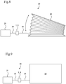
- the exercise support device 20 includes an air supply device 21, a bellows gas chamber member 22, a vent pipe 23 connecting the air supply device 21 and the gas chamber member 22, and the relief valve 1, 8 connected to the vent pipe 23.
- the gas chamber member 22 may be made of an elastic material such as rubber as an example.
- the relief valve 1, 8 operates as a pressure release valve, and the bellows gas chamber member 22 is expanded into a fan shape by air supplied from the air supply device 21 (the state in Fig. 8 ).
- the valve body 4, 11 When pressure in the gas chamber member 22 exceeds set pressure, the valve body 4, 11 is opened to discharge air in the vent pipe 23 and the gas chamber member 22 from the exhaust port 2, 10b to the outside. This contracts the gas chamber member 22.
- the valve body 4, 8 is closed, and air is again supplied to the gas chamber member 22 to expand the gas chamber member 22.
- the gas chamber member 22 expanded/contracted in this manner can be brought into contact with a predetermined site of a human body to passively move or massage the predetermined site. More specifically, the exercise support device 20 provides prevention of contracture of proximal and distal regions of upper and lower limbs, trunk, palm, neck region, or the like by expanding/contracting the gas chamber member 22 to passively move various sites of the human body, prevention of bedsore by improved circulation, support of deep breathing (raising upper limbs by extracting/contracting the gas chamber member can expand intercostal muscle to support costal breathing.
- Exercise of lower limbs and trunk by expansion/contraction of the gas chamber member can move abdominal organs and indirectly move diaphragm to support abdominal breathing), relaxing effects (holding the expanded/contracted gas chamber member in arms and feeling breathing rhythm can bring a relaxing state to restrain cerebral excitation).
- the purification device 30 includes a blower 31, an aeration pipe 32, and the relief valve 1, 8 connected to the aeration pipe 32.
- the aeration pipe 32 communicates with an inside of a purification tank 33 that purifies an object to be purified such as dirt.
- the purification device air blown by the blower 31 is supplied by the aeration pipe 32 into the purification tank 33 to aerate the object to be purified in the purification tank 33, and thus air require for activity of aerobic microorganisms existing in the object to be purified is supplied so that the microorganisms decompose the object to be purified.
- the aerobic microorganisms are not essential for the purification device, but the purification device may be configured so that the blower 31 and the aeration pipe 32 are used to purify the object to be purified in the purification tank 33 by aeration.
- the blower 31 may be damaged by an abnormal pressure increase.
- the valve body 4, 11 can be opened to release and reduce pressure in the aeration pipe 32 to prevent damage to the blower 31.
- the abnormal pressure increase due to clogging of the aeration pipe 32 can be detected by opening/closing sound of the relief valve 1, 8, thereby facilitating inspection.
- a diving regulator will be described as a further example of a device including the relief valve 1, 8.
- Divers carry a spare regulator (octopus) in case of impaired consciousness or breathing trouble during scuba diving.
- the octopus does not have an automatic artificial respiration function, rebreathing in water is impossible.
- a rescue operation cannot be performed until a diver in trouble is carried onto a boat or the ground, and thus lifesaving has been extremely difficult.
- the diving regulator of this embodiment includes the relief valve 1, 8 in a vent path very close to a mouth piece to which air reduced in pressure by the regulator is supplied, thereby adding an automatic artificial respiration function to the diving regulator.
- the relief valve 1, 8 can be automatically opened, and when the lungs contract to reduce the pressure, the valve can be automatically closed, thereby allowing artificial respiration even in water.
- a power source of the relief valve 1, 8 is air pressure and no electricity or electronic component is used, there is no risk of failure when getting wet, thereby achieving a stable operation in water.
- using plastic allows mass production at low cost.
- the relief valve 1, 8 itself or the exhaust port provided in the relief valve 1, 8 must be mounted downward so that water stored therein is easily discharged.
Landscapes
- Health & Medical Sciences (AREA)
- Engineering & Computer Science (AREA)
- General Engineering & Computer Science (AREA)
- Life Sciences & Earth Sciences (AREA)
- Veterinary Medicine (AREA)
- Public Health (AREA)
- General Health & Medical Sciences (AREA)
- Animal Behavior & Ethology (AREA)
- Pulmonology (AREA)
- Mechanical Engineering (AREA)
- Anesthesiology (AREA)
- Heart & Thoracic Surgery (AREA)
- Emergency Medicine (AREA)
- Epidemiology (AREA)
- Rehabilitation Therapy (AREA)
- Pain & Pain Management (AREA)
- Physical Education & Sports Medicine (AREA)
- Biomedical Technology (AREA)
- Hematology (AREA)
- Cardiology (AREA)
- Safety Valves (AREA)
- Valve Housings (AREA)
Applications Claiming Priority (2)
| Application Number | Priority Date | Filing Date | Title |
|---|---|---|---|
| JP2015257752 | 2015-12-31 | ||
| PCT/JP2016/089187 WO2017115866A1 (ja) | 2015-12-31 | 2016-12-28 | リリーフ弁 |
Publications (3)
| Publication Number | Publication Date |
|---|---|
| EP3399219A1 EP3399219A1 (en) | 2018-11-07 |
| EP3399219A4 EP3399219A4 (en) | 2019-07-24 |
| EP3399219B1 true EP3399219B1 (en) | 2020-07-29 |
Family
ID=59224808
Family Applications (1)
| Application Number | Title | Priority Date | Filing Date |
|---|---|---|---|
| EP16881840.9A Active EP3399219B1 (en) | 2015-12-31 | 2016-12-28 | Relief valve |
Country Status (6)
| Country | Link |
|---|---|
| US (1) | US11224716B2 (ja) |
| EP (1) | EP3399219B1 (ja) |
| JP (3) | JP6780861B2 (ja) |
| CN (1) | CN108431471B (ja) |
| ES (1) | ES2818532T3 (ja) |
| WO (1) | WO2017115866A1 (ja) |
Families Citing this family (7)
| Publication number | Priority date | Publication date | Assignee | Title |
|---|---|---|---|---|
| DE102017119833A1 (de) * | 2017-08-29 | 2019-02-28 | Hengst Filter Systems (Kunshan) Co. Ltd. | Druckbegrenzungsventil |
| FR3073918B1 (fr) * | 2017-11-21 | 2019-11-01 | Zodiac Aerotechnics | Dispositif anti-retour de fluide monobloc dans un aeronef et procede de fabrication d'un tel dispositif |
| US10627001B2 (en) * | 2018-06-29 | 2020-04-21 | Sulzer Mixpac Ag | Check valve system |
| IT201900004978A1 (it) | 2019-04-03 | 2020-10-03 | Nuovo Pignone Tecnologie Srl | Una valvola completamente attuata per una macchina alternativa e macchina alternativa comprendente detta valvola |
| JP7457359B2 (ja) | 2020-07-18 | 2024-03-28 | 直之 石北 | 人工呼吸器 |
| JP2022060110A (ja) | 2020-10-02 | 2022-04-14 | 直之 石北 | 人工呼吸器 |
| WO2023127920A1 (ja) * | 2021-12-28 | 2023-07-06 | 孝 中島 | 情報処理方法、プログラム、非一時的コンピュータ可読記憶媒体及び電子デバイス |
Family Cites Families (28)
| Publication number | Priority date | Publication date | Assignee | Title |
|---|---|---|---|---|
| US2588157A (en) * | 1946-04-19 | 1952-03-04 | Phillips Petroleum Co | Relief valve |
| GB949221A (en) * | 1960-07-19 | 1964-02-12 | Kidde Walter Co Ltd | Improvements in or relating to breathing apparatus |
| JPS4710873Y1 (ja) | 1968-07-19 | 1972-04-21 | ||
| JPS51128030U (ja) * | 1975-04-14 | 1976-10-16 | ||
| JPS59147964U (ja) * | 1983-03-25 | 1984-10-03 | シ−ケ−デイ株式会社 | リリ−フ弁 |
| JPH0833114B2 (ja) * | 1987-05-14 | 1996-03-29 | 愛三工業株式会社 | バキユ−ムリミツタ |
| US4932434A (en) * | 1988-01-25 | 1990-06-12 | Taylor Wesley L | Adjustable safety relief valve |
| JPH01238781A (ja) * | 1988-03-17 | 1989-09-22 | Mitsubishi Electric Corp | 安全弁 |
| JP2717973B2 (ja) * | 1988-10-20 | 1998-02-25 | 東急車輌製造株式会社 | 圧力制御弁 |
| US5094266A (en) | 1991-05-22 | 1992-03-10 | Ledbetter Harold J | Pressure release valve |
| US5203372A (en) * | 1991-11-08 | 1993-04-20 | Girard Equipment Inc. | Jet-flow pressure relief vent |
| US7354410B2 (en) * | 2004-02-23 | 2008-04-08 | Tyco Healthcare Group Lp | Compression treatment system |
| JP2005288045A (ja) | 2004-04-06 | 2005-10-20 | Yoshibumi Tanaka | 気道内圧異常上昇防止法と装置 |
| DE102004033022A1 (de) * | 2004-07-08 | 2006-02-02 | Ina-Schaeffler Kg | Rückschlagventil |
| US7513270B2 (en) * | 2005-01-14 | 2009-04-07 | Flow-Safe, Inc. | Balanced safety relief valve |
| CN2821327Y (zh) * | 2005-08-10 | 2006-09-27 | 胡立桥 | 自锁式高压单流阀 |
| CN101761675A (zh) * | 2009-11-20 | 2010-06-30 | 卓旦春 | 热水器用新型安全阀 |
| JP2011182949A (ja) * | 2010-03-09 | 2011-09-22 | Yoshida Dental Mfg Co Ltd | 高齢者対応歯科診療椅子用マットおよび歯科診療椅子 |
| US8534283B2 (en) * | 2010-07-19 | 2013-09-17 | Mercury Enterprises, Inc. | Peep valve with filter |
| US9072859B2 (en) | 2011-05-31 | 2015-07-07 | Naoyuki Ishikita | Anesthetic inhalation aid device and attachment used for the same |
| JP5684191B2 (ja) * | 2012-04-23 | 2015-03-11 | 株式会社タカギ | シリンダ弁及び水栓器具 |
| US9562616B2 (en) * | 2013-01-15 | 2017-02-07 | Honeywell International Inc. | Spring assemblies for use in gas turbine engines and methods for their manufacture |
| CN105102869B (zh) | 2013-02-08 | 2017-06-09 | 诺格伦有限责任公司 | 比例阀 |
| CN106164559A (zh) * | 2014-03-26 | 2016-11-23 | 沙特基础工业全球技术有限公司 | 弹性可变形的聚合物制品以及用于吸收循环压力偏移的方法 |
| US9482354B2 (en) * | 2014-04-15 | 2016-11-01 | Girard Equipment, Inc. | Super high flow pressure relief vent |
| US10240679B2 (en) * | 2014-06-13 | 2019-03-26 | Horiba Stec, Co., Ltd. | High conductance valve for fluids and vapors |
| US20160097434A1 (en) * | 2014-10-03 | 2016-04-07 | Tyco Electronics Corporation | Bonded helical compression spring |
| JP6478585B2 (ja) * | 2014-11-26 | 2019-03-06 | 株式会社不二工機 | 流路切換弁 |
-
2016
- 2016-12-28 CN CN201680068564.6A patent/CN108431471B/zh active Active
- 2016-12-28 EP EP16881840.9A patent/EP3399219B1/en active Active
- 2016-12-28 ES ES16881840T patent/ES2818532T3/es active Active
- 2016-12-28 JP JP2017559248A patent/JP6780861B2/ja active Active
- 2016-12-28 US US16/067,192 patent/US11224716B2/en active Active
- 2016-12-28 WO PCT/JP2016/089187 patent/WO2017115866A1/ja active Application Filing
-
2020
- 2020-10-08 JP JP2020170776A patent/JP6985762B2/ja active Active
-
2021
- 2021-11-18 JP JP2021188187A patent/JP7283801B2/ja active Active
Non-Patent Citations (1)
| Title |
|---|
| None * |
Also Published As
| Publication number | Publication date |
|---|---|
| WO2017115866A1 (ja) | 2017-07-06 |
| JP2021001695A (ja) | 2021-01-07 |
| EP3399219A4 (en) | 2019-07-24 |
| CN108431471A (zh) | 2018-08-21 |
| JPWO2017115866A1 (ja) | 2018-11-08 |
| JP2022022248A (ja) | 2022-02-03 |
| ES2818532T3 (es) | 2021-04-13 |
| JP6985762B2 (ja) | 2021-12-22 |
| JP7283801B2 (ja) | 2023-05-30 |
| EP3399219A1 (en) | 2018-11-07 |
| US20190022346A1 (en) | 2019-01-24 |
| CN108431471B (zh) | 2020-11-10 |
| JP6780861B2 (ja) | 2020-11-04 |
| US11224716B2 (en) | 2022-01-18 |
Similar Documents
| Publication | Publication Date | Title |
|---|---|---|
| EP3399219B1 (en) | Relief valve | |
| US20210178109A1 (en) | Breathing assistance apparatus | |
| US20110197892A1 (en) | Enhanced manually actuated pressure controlled modulator technology | |
| WO1999019014A1 (en) | Pulmonary pressure modulator | |
| US10828459B2 (en) | Breath powered positive airway pressure device | |
| US10576241B2 (en) | Breath powered positive airway pressure device | |
| EP3202449B1 (en) | Elbow connector assembly with anti-asphyxia valve structure for respiratory mask | |
| CA3110720A1 (en) | Breath powered positive airway pressure device | |
| US20230405259A1 (en) | Ventilator |
Legal Events
| Date | Code | Title | Description |
|---|---|---|---|
| STAA | Information on the status of an ep patent application or granted ep patent |
Free format text: STATUS: THE INTERNATIONAL PUBLICATION HAS BEEN MADE |
|
| PUAI | Public reference made under article 153(3) epc to a published international application that has entered the european phase |
Free format text: ORIGINAL CODE: 0009012 |
|
| STAA | Information on the status of an ep patent application or granted ep patent |
Free format text: STATUS: REQUEST FOR EXAMINATION WAS MADE |
|
| 17P | Request for examination filed |
Effective date: 20180704 |
|
| AK | Designated contracting states |
Kind code of ref document: A1 Designated state(s): AL AT BE BG CH CY CZ DE DK EE ES FI FR GB GR HR HU IE IS IT LI LT LU LV MC MK MT NL NO PL PT RO RS SE SI SK SM TR |
|
| AX | Request for extension of the european patent |
Extension state: BA ME |
|
| DAV | Request for validation of the european patent (deleted) | ||
| DAX | Request for extension of the european patent (deleted) | ||
| A4 | Supplementary search report drawn up and despatched |
Effective date: 20190625 |
|
| RIC1 | Information provided on ipc code assigned before grant |
Ipc: A61M 16/01 20060101ALI20190618BHEP Ipc: F16K 17/06 20060101ALI20190618BHEP Ipc: F16K 17/04 20060101AFI20190618BHEP |
|
| GRAP | Despatch of communication of intention to grant a patent |
Free format text: ORIGINAL CODE: EPIDOSNIGR1 |
|
| STAA | Information on the status of an ep patent application or granted ep patent |
Free format text: STATUS: GRANT OF PATENT IS INTENDED |
|
| INTG | Intention to grant announced |
Effective date: 20200406 |
|
| GRAS | Grant fee paid |
Free format text: ORIGINAL CODE: EPIDOSNIGR3 |
|
| GRAA | (expected) grant |
Free format text: ORIGINAL CODE: 0009210 |
|
| STAA | Information on the status of an ep patent application or granted ep patent |
Free format text: STATUS: THE PATENT HAS BEEN GRANTED |
|
| AK | Designated contracting states |
Kind code of ref document: B1 Designated state(s): AL AT BE BG CH CY CZ DE DK EE ES FI FR GB GR HR HU IE IS IT LI LT LU LV MC MK MT NL NO PL PT RO RS SE SI SK SM TR |
|
| REG | Reference to a national code |
Ref country code: CH Ref legal event code: EP |
|
| REG | Reference to a national code |
Ref country code: AT Ref legal event code: REF Ref document number: 1296201 Country of ref document: AT Kind code of ref document: T Effective date: 20200815 |
|
| REG | Reference to a national code |
Ref country code: IE Ref legal event code: FG4D |
|
| REG | Reference to a national code |
Ref country code: DE Ref legal event code: R096 Ref document number: 602016041090 Country of ref document: DE |
|
| REG | Reference to a national code |
Ref country code: LT Ref legal event code: MG4D |
|
| REG | Reference to a national code |
Ref country code: NL Ref legal event code: MP Effective date: 20200729 |
|
| REG | Reference to a national code |
Ref country code: AT Ref legal event code: MK05 Ref document number: 1296201 Country of ref document: AT Kind code of ref document: T Effective date: 20200729 |
|
| PG25 | Lapsed in a contracting state [announced via postgrant information from national office to epo] |
Ref country code: BG Free format text: LAPSE BECAUSE OF FAILURE TO SUBMIT A TRANSLATION OF THE DESCRIPTION OR TO PAY THE FEE WITHIN THE PRESCRIBED TIME-LIMIT Effective date: 20201029 Ref country code: AT Free format text: LAPSE BECAUSE OF FAILURE TO SUBMIT A TRANSLATION OF THE DESCRIPTION OR TO PAY THE FEE WITHIN THE PRESCRIBED TIME-LIMIT Effective date: 20200729 Ref country code: GR Free format text: LAPSE BECAUSE OF FAILURE TO SUBMIT A TRANSLATION OF THE DESCRIPTION OR TO PAY THE FEE WITHIN THE PRESCRIBED TIME-LIMIT Effective date: 20201030 Ref country code: NO Free format text: LAPSE BECAUSE OF FAILURE TO SUBMIT A TRANSLATION OF THE DESCRIPTION OR TO PAY THE FEE WITHIN THE PRESCRIBED TIME-LIMIT Effective date: 20201029 Ref country code: PT Free format text: LAPSE BECAUSE OF FAILURE TO SUBMIT A TRANSLATION OF THE DESCRIPTION OR TO PAY THE FEE WITHIN THE PRESCRIBED TIME-LIMIT Effective date: 20201130 Ref country code: SE Free format text: LAPSE BECAUSE OF FAILURE TO SUBMIT A TRANSLATION OF THE DESCRIPTION OR TO PAY THE FEE WITHIN THE PRESCRIBED TIME-LIMIT Effective date: 20200729 Ref country code: FI Free format text: LAPSE BECAUSE OF FAILURE TO SUBMIT A TRANSLATION OF THE DESCRIPTION OR TO PAY THE FEE WITHIN THE PRESCRIBED TIME-LIMIT Effective date: 20200729 Ref country code: HR Free format text: LAPSE BECAUSE OF FAILURE TO SUBMIT A TRANSLATION OF THE DESCRIPTION OR TO PAY THE FEE WITHIN THE PRESCRIBED TIME-LIMIT Effective date: 20200729 Ref country code: LT Free format text: LAPSE BECAUSE OF FAILURE TO SUBMIT A TRANSLATION OF THE DESCRIPTION OR TO PAY THE FEE WITHIN THE PRESCRIBED TIME-LIMIT Effective date: 20200729 |
|
| PG25 | Lapsed in a contracting state [announced via postgrant information from national office to epo] |
Ref country code: IS Free format text: LAPSE BECAUSE OF FAILURE TO SUBMIT A TRANSLATION OF THE DESCRIPTION OR TO PAY THE FEE WITHIN THE PRESCRIBED TIME-LIMIT Effective date: 20201129 Ref country code: PL Free format text: LAPSE BECAUSE OF FAILURE TO SUBMIT A TRANSLATION OF THE DESCRIPTION OR TO PAY THE FEE WITHIN THE PRESCRIBED TIME-LIMIT Effective date: 20200729 Ref country code: LV Free format text: LAPSE BECAUSE OF FAILURE TO SUBMIT A TRANSLATION OF THE DESCRIPTION OR TO PAY THE FEE WITHIN THE PRESCRIBED TIME-LIMIT Effective date: 20200729 Ref country code: RS Free format text: LAPSE BECAUSE OF FAILURE TO SUBMIT A TRANSLATION OF THE DESCRIPTION OR TO PAY THE FEE WITHIN THE PRESCRIBED TIME-LIMIT Effective date: 20200729 |
|
| PG25 | Lapsed in a contracting state [announced via postgrant information from national office to epo] |
Ref country code: NL Free format text: LAPSE BECAUSE OF FAILURE TO SUBMIT A TRANSLATION OF THE DESCRIPTION OR TO PAY THE FEE WITHIN THE PRESCRIBED TIME-LIMIT Effective date: 20200729 |
|
| REG | Reference to a national code |
Ref country code: ES Ref legal event code: FG2A Ref document number: 2818532 Country of ref document: ES Kind code of ref document: T3 Effective date: 20210413 |
|
| PG25 | Lapsed in a contracting state [announced via postgrant information from national office to epo] |
Ref country code: RO Free format text: LAPSE BECAUSE OF FAILURE TO SUBMIT A TRANSLATION OF THE DESCRIPTION OR TO PAY THE FEE WITHIN THE PRESCRIBED TIME-LIMIT Effective date: 20200729 Ref country code: DK Free format text: LAPSE BECAUSE OF FAILURE TO SUBMIT A TRANSLATION OF THE DESCRIPTION OR TO PAY THE FEE WITHIN THE PRESCRIBED TIME-LIMIT Effective date: 20200729 Ref country code: CZ Free format text: LAPSE BECAUSE OF FAILURE TO SUBMIT A TRANSLATION OF THE DESCRIPTION OR TO PAY THE FEE WITHIN THE PRESCRIBED TIME-LIMIT Effective date: 20200729 Ref country code: EE Free format text: LAPSE BECAUSE OF FAILURE TO SUBMIT A TRANSLATION OF THE DESCRIPTION OR TO PAY THE FEE WITHIN THE PRESCRIBED TIME-LIMIT Effective date: 20200729 Ref country code: SM Free format text: LAPSE BECAUSE OF FAILURE TO SUBMIT A TRANSLATION OF THE DESCRIPTION OR TO PAY THE FEE WITHIN THE PRESCRIBED TIME-LIMIT Effective date: 20200729 |
|
| REG | Reference to a national code |
Ref country code: DE Ref legal event code: R097 Ref document number: 602016041090 Country of ref document: DE |
|
| PG25 | Lapsed in a contracting state [announced via postgrant information from national office to epo] |
Ref country code: AL Free format text: LAPSE BECAUSE OF FAILURE TO SUBMIT A TRANSLATION OF THE DESCRIPTION OR TO PAY THE FEE WITHIN THE PRESCRIBED TIME-LIMIT Effective date: 20200729 |
|
| PLBE | No opposition filed within time limit |
Free format text: ORIGINAL CODE: 0009261 |
|
| STAA | Information on the status of an ep patent application or granted ep patent |
Free format text: STATUS: NO OPPOSITION FILED WITHIN TIME LIMIT |
|
| PG25 | Lapsed in a contracting state [announced via postgrant information from national office to epo] |
Ref country code: SK Free format text: LAPSE BECAUSE OF FAILURE TO SUBMIT A TRANSLATION OF THE DESCRIPTION OR TO PAY THE FEE WITHIN THE PRESCRIBED TIME-LIMIT Effective date: 20200729 |
|
| 26N | No opposition filed |
Effective date: 20210430 |
|
| REG | Reference to a national code |
Ref country code: CH Ref legal event code: PL |
|
| PG25 | Lapsed in a contracting state [announced via postgrant information from national office to epo] |
Ref country code: SI Free format text: LAPSE BECAUSE OF FAILURE TO SUBMIT A TRANSLATION OF THE DESCRIPTION OR TO PAY THE FEE WITHIN THE PRESCRIBED TIME-LIMIT Effective date: 20200729 Ref country code: MC Free format text: LAPSE BECAUSE OF FAILURE TO SUBMIT A TRANSLATION OF THE DESCRIPTION OR TO PAY THE FEE WITHIN THE PRESCRIBED TIME-LIMIT Effective date: 20200729 |
|
| REG | Reference to a national code |
Ref country code: BE Ref legal event code: MM Effective date: 20201231 |
|
| PG25 | Lapsed in a contracting state [announced via postgrant information from national office to epo] |
Ref country code: IE Free format text: LAPSE BECAUSE OF NON-PAYMENT OF DUE FEES Effective date: 20201228 Ref country code: LU Free format text: LAPSE BECAUSE OF NON-PAYMENT OF DUE FEES Effective date: 20201228 |
|
| PG25 | Lapsed in a contracting state [announced via postgrant information from national office to epo] |
Ref country code: LI Free format text: LAPSE BECAUSE OF NON-PAYMENT OF DUE FEES Effective date: 20201231 Ref country code: CH Free format text: LAPSE BECAUSE OF NON-PAYMENT OF DUE FEES Effective date: 20201231 |
|
| PG25 | Lapsed in a contracting state [announced via postgrant information from national office to epo] |
Ref country code: TR Free format text: LAPSE BECAUSE OF FAILURE TO SUBMIT A TRANSLATION OF THE DESCRIPTION OR TO PAY THE FEE WITHIN THE PRESCRIBED TIME-LIMIT Effective date: 20200729 Ref country code: MT Free format text: LAPSE BECAUSE OF FAILURE TO SUBMIT A TRANSLATION OF THE DESCRIPTION OR TO PAY THE FEE WITHIN THE PRESCRIBED TIME-LIMIT Effective date: 20200729 Ref country code: CY Free format text: LAPSE BECAUSE OF FAILURE TO SUBMIT A TRANSLATION OF THE DESCRIPTION OR TO PAY THE FEE WITHIN THE PRESCRIBED TIME-LIMIT Effective date: 20200729 |
|
| PG25 | Lapsed in a contracting state [announced via postgrant information from national office to epo] |
Ref country code: MK Free format text: LAPSE BECAUSE OF FAILURE TO SUBMIT A TRANSLATION OF THE DESCRIPTION OR TO PAY THE FEE WITHIN THE PRESCRIBED TIME-LIMIT Effective date: 20200729 |
|
| PG25 | Lapsed in a contracting state [announced via postgrant information from national office to epo] |
Ref country code: BE Free format text: LAPSE BECAUSE OF NON-PAYMENT OF DUE FEES Effective date: 20201231 |
|
| PGFP | Annual fee paid to national office [announced via postgrant information from national office to epo] |
Ref country code: IT Payment date: 20221228 Year of fee payment: 7 |
|
| P01 | Opt-out of the competence of the unified patent court (upc) registered |
Effective date: 20230518 |
|
| PGFP | Annual fee paid to national office [announced via postgrant information from national office to epo] |
Ref country code: GB Payment date: 20231220 Year of fee payment: 8 |
|
| PGFP | Annual fee paid to national office [announced via postgrant information from national office to epo] |
Ref country code: FR Payment date: 20231103 Year of fee payment: 8 |
|
| PGFP | Annual fee paid to national office [announced via postgrant information from national office to epo] |
Ref country code: ES Payment date: 20240118 Year of fee payment: 8 |
|
| PGFP | Annual fee paid to national office [announced via postgrant information from national office to epo] |
Ref country code: DE Payment date: 20240117 Year of fee payment: 8 |