EP3398583A1 - Système comportant un adaptateur pour le transfert fermé de fluides - Google Patents
Système comportant un adaptateur pour le transfert fermé de fluides Download PDFInfo
- Publication number
- EP3398583A1 EP3398583A1 EP18175946.5A EP18175946A EP3398583A1 EP 3398583 A1 EP3398583 A1 EP 3398583A1 EP 18175946 A EP18175946 A EP 18175946A EP 3398583 A1 EP3398583 A1 EP 3398583A1
- Authority
- EP
- European Patent Office
- Prior art keywords
- vial
- connector
- access device
- housing
- adapter
- Prior art date
- Legal status (The legal status is an assumption and is not a legal conclusion. Google has not performed a legal analysis and makes no representation as to the accuracy of the status listed.)
- Pending
Links
Images


Classifications
-
- A—HUMAN NECESSITIES
- A61—MEDICAL OR VETERINARY SCIENCE; HYGIENE
- A61J—CONTAINERS SPECIALLY ADAPTED FOR MEDICAL OR PHARMACEUTICAL PURPOSES; DEVICES OR METHODS SPECIALLY ADAPTED FOR BRINGING PHARMACEUTICAL PRODUCTS INTO PARTICULAR PHYSICAL OR ADMINISTERING FORMS; DEVICES FOR ADMINISTERING FOOD OR MEDICINES ORALLY; BABY COMFORTERS; DEVICES FOR RECEIVING SPITTLE
- A61J1/00—Containers specially adapted for medical or pharmaceutical purposes
- A61J1/14—Details; Accessories therefor
- A61J1/20—Arrangements for transferring or mixing fluids, e.g. from vial to syringe
- A61J1/2003—Accessories used in combination with means for transfer or mixing of fluids, e.g. for activating fluid flow, separating fluids, filtering fluid or venting
- A61J1/2006—Piercing means
- A61J1/201—Piercing means having one piercing end
-
- A—HUMAN NECESSITIES
- A61—MEDICAL OR VETERINARY SCIENCE; HYGIENE
- A61J—CONTAINERS SPECIALLY ADAPTED FOR MEDICAL OR PHARMACEUTICAL PURPOSES; DEVICES OR METHODS SPECIALLY ADAPTED FOR BRINGING PHARMACEUTICAL PRODUCTS INTO PARTICULAR PHYSICAL OR ADMINISTERING FORMS; DEVICES FOR ADMINISTERING FOOD OR MEDICINES ORALLY; BABY COMFORTERS; DEVICES FOR RECEIVING SPITTLE
- A61J1/00—Containers specially adapted for medical or pharmaceutical purposes
- A61J1/14—Details; Accessories therefor
- A61J1/20—Arrangements for transferring or mixing fluids, e.g. from vial to syringe
- A61J1/2003—Accessories used in combination with means for transfer or mixing of fluids, e.g. for activating fluid flow, separating fluids, filtering fluid or venting
- A61J1/2079—Filtering means
-
- A—HUMAN NECESSITIES
- A61—MEDICAL OR VETERINARY SCIENCE; HYGIENE
- A61J—CONTAINERS SPECIALLY ADAPTED FOR MEDICAL OR PHARMACEUTICAL PURPOSES; DEVICES OR METHODS SPECIALLY ADAPTED FOR BRINGING PHARMACEUTICAL PRODUCTS INTO PARTICULAR PHYSICAL OR ADMINISTERING FORMS; DEVICES FOR ADMINISTERING FOOD OR MEDICINES ORALLY; BABY COMFORTERS; DEVICES FOR RECEIVING SPITTLE
- A61J1/00—Containers specially adapted for medical or pharmaceutical purposes
- A61J1/14—Details; Accessories therefor
- A61J1/1406—Septums, pierceable membranes
-
- A—HUMAN NECESSITIES
- A61—MEDICAL OR VETERINARY SCIENCE; HYGIENE
- A61J—CONTAINERS SPECIALLY ADAPTED FOR MEDICAL OR PHARMACEUTICAL PURPOSES; DEVICES OR METHODS SPECIALLY ADAPTED FOR BRINGING PHARMACEUTICAL PRODUCTS INTO PARTICULAR PHYSICAL OR ADMINISTERING FORMS; DEVICES FOR ADMINISTERING FOOD OR MEDICINES ORALLY; BABY COMFORTERS; DEVICES FOR RECEIVING SPITTLE
- A61J1/00—Containers specially adapted for medical or pharmaceutical purposes
- A61J1/14—Details; Accessories therefor
- A61J1/20—Arrangements for transferring or mixing fluids, e.g. from vial to syringe
- A61J1/2003—Accessories used in combination with means for transfer or mixing of fluids, e.g. for activating fluid flow, separating fluids, filtering fluid or venting
- A61J1/2048—Connecting means
- A61J1/2055—Connecting means having gripping means
-
- A—HUMAN NECESSITIES
- A61—MEDICAL OR VETERINARY SCIENCE; HYGIENE
- A61J—CONTAINERS SPECIALLY ADAPTED FOR MEDICAL OR PHARMACEUTICAL PURPOSES; DEVICES OR METHODS SPECIALLY ADAPTED FOR BRINGING PHARMACEUTICAL PRODUCTS INTO PARTICULAR PHYSICAL OR ADMINISTERING FORMS; DEVICES FOR ADMINISTERING FOOD OR MEDICINES ORALLY; BABY COMFORTERS; DEVICES FOR RECEIVING SPITTLE
- A61J1/00—Containers specially adapted for medical or pharmaceutical purposes
- A61J1/14—Details; Accessories therefor
- A61J1/20—Arrangements for transferring or mixing fluids, e.g. from vial to syringe
- A61J1/2003—Accessories used in combination with means for transfer or mixing of fluids, e.g. for activating fluid flow, separating fluids, filtering fluid or venting
- A61J1/2068—Venting means
- A61J1/2072—Venting means for internal venting
-
- A—HUMAN NECESSITIES
- A61—MEDICAL OR VETERINARY SCIENCE; HYGIENE
- A61J—CONTAINERS SPECIALLY ADAPTED FOR MEDICAL OR PHARMACEUTICAL PURPOSES; DEVICES OR METHODS SPECIALLY ADAPTED FOR BRINGING PHARMACEUTICAL PRODUCTS INTO PARTICULAR PHYSICAL OR ADMINISTERING FORMS; DEVICES FOR ADMINISTERING FOOD OR MEDICINES ORALLY; BABY COMFORTERS; DEVICES FOR RECEIVING SPITTLE
- A61J1/00—Containers specially adapted for medical or pharmaceutical purposes
- A61J1/14—Details; Accessories therefor
- A61J1/20—Arrangements for transferring or mixing fluids, e.g. from vial to syringe
- A61J1/2003—Accessories used in combination with means for transfer or mixing of fluids, e.g. for activating fluid flow, separating fluids, filtering fluid or venting
- A61J1/2079—Filtering means
- A61J1/2086—Filtering means for fluid filtration
-
- A—HUMAN NECESSITIES
- A61—MEDICAL OR VETERINARY SCIENCE; HYGIENE
- A61J—CONTAINERS SPECIALLY ADAPTED FOR MEDICAL OR PHARMACEUTICAL PURPOSES; DEVICES OR METHODS SPECIALLY ADAPTED FOR BRINGING PHARMACEUTICAL PRODUCTS INTO PARTICULAR PHYSICAL OR ADMINISTERING FORMS; DEVICES FOR ADMINISTERING FOOD OR MEDICINES ORALLY; BABY COMFORTERS; DEVICES FOR RECEIVING SPITTLE
- A61J1/00—Containers specially adapted for medical or pharmaceutical purposes
- A61J1/14—Details; Accessories therefor
- A61J1/20—Arrangements for transferring or mixing fluids, e.g. from vial to syringe
- A61J1/2096—Combination of a vial and a syringe for transferring or mixing their contents
Definitions
- the present disclosure relates generally to a system for the closed transfer of fluids. More particularly, the present disclosure relates to a system that accommodates vials having different sizes and provides leak-proof sealing and pressure equalization during engagement of a cannula with a vial, during transfer of a substance from a vial chamber to a barrel chamber via the cannula, and during disengagement of the cannula from the vial.
- Health care providers reconstituting, transporting, and administering hazardous drugs, such as cancer treatments, can put themselves at risk of exposure to these medications and present a major hazard in the health care environment. For example, nurses treating cancer patients risk being exposed to chemotherapy drugs and their toxic effects. Unintentional chemotherapy exposure can affect the nervous system, impair the reproductive system, and bring an increased risk of developing blood cancers in the future. In order to reduce the risk of health care providers being exposed to toxic drugs, the closed transfer of these drugs becomes important.
- Some drugs must be dissolved or diluted before they are administered, which involves transferring a solvent from one container to a sealed vial containing the drug in powder or liquid form, by means of a needle. Drugs may be inadvertently released into the atmosphere in gas form or by way of aerosolization, during the withdrawal of the needle from the vial, and while the needle is inside the vial if any differential pressure exists between the interior of the vial and the surrounding atmosphere.
- a vial access device in one aspect of the present invention, includes an outer housing defining an annular space and an inner space, an inner housing having a body defining a central opening with at least a portion of the inner housing positioned within the inner space of the outer housing, and a connector configured to engage a mating connector with the connector having a body defining a central passageway and a flange that extends radially outward from the body.
- the flange and the housing define a filter space that is in fluid communication with the annular space.
- a pressure equalization system is positioned within the annular space of the outer housing with the pressure equalization system configured to change a volume of space defined by the annular space and the pressure equalization system.
- the device also includes a vial connection element configured to be secured to a vial with the vial connection element having a body and a spike member extending from the body.
- the spike member defines a fluid passageway and a vent passageway with the fluid passageway in fluid communication with the central passageway of the connector and the vent passageway in fluid communication with the filter space and the annular space.
- a filter is positioned in the filter space.
- the vial access device may further include a top cap having a body secured to the inner housing with the body of the top cap defining a recessed portion that receives a portion of the connector.
- the top cap may include a gripping surface configured to allow a user to remove the top cap from the inner housing.
- the body of the vial connection element may define a central passageway, with the body of the vial connection element received within the central passageway of the connector with the central passageway of the vial connection element aligned with the central passageway of the connector.
- An O-ring may be positioned between the vial connection element and the connector.
- the flange of the connector may abut a ledge defined by the outer housing, with the ledge extending radially inward into the inner space of the outer housing.
- the inner housing may have a top surface having a shape that conforms to an outer surface of the outer housing.
- the body of the inner housing may have a cylindrical portion extending axially into the inner space of the outer housing.
- a membrane may be positioned on the connector adjacent to the central passageway of the connector.
- the pressure equalization system may include a toroidal balloon configured to expand axially outer of the annular space of the outer housing.
- the filter may be annular and may be a hydrophobic filter.
- distal refers to a direction generally toward an end of a vial access device adapted for contact with a container, such as a vial
- proximal refers to the opposite direction of distal, i.e., away from the end of a vial access device adapted for engagement with the container.
- a system 10 for the closed transfer of fluids includes a vial access device 12 and an adapter 14 sized for movement within the vial access device 12 as described in more detail below.
- vial access device 12 includes outer housing 16, inner housing 18, connector 20, top cap housing 22, and pressure equalization system 24.
- System 10 provides a device capable of accommodating a plurality of vials having different sizes.
- System 10 also provides substantially leak-proof sealing and pressure equalization during engagement of a cannula with a vial, during transfer of a substance from a vial chamber to a barrel chamber via the cannula, and during disengagement of the cannula from the vial.
- System 10 is compatible with a needle and syringe assembly for accessing a medication contained within a vial for administering the medication to a patient.
- System 10 is also compatible to be used with a drug reconstitution system.
- vial access device 12 includes a vial access housing 26 having outer housing 16 and inner housing 18.
- System 10 provides a device capable of accommodating a plurality of vials having different sizes.
- Vial access device 12 is configured to establish fluid communication between a first container, e.g., a first vial having a first vial size, and a second container, e.g., an injector and/or syringe assembly.
- first container e.g., a first vial having a first vial size
- second container e.g., an injector and/or syringe assembly.
- vial access device 12 is attachable to a first vial 80 as described in more detail below. Referring to Figs.
- first vial 80 defining a first vial size 81 may be a standard drug vial of any type having an open head portion 83 covered by a pierceable septum 84 of an elastomeric material. Walls 85 of first vial 80 define a vial chamber 86 for containing a first substance 88. First vial 80 includes a flange 87 located adjacent open head portion 83. Vial septum 84 is engaged with head portion 83 of first vial 80 to seal the first substance 88 within vial chamber 86.
- adapter 14 of system 10 is configured to establish fluid communication between a first container, e.g., a second vial having a second vial size, and a second container, e.g., an injector and/or syringe assembly.
- a second vial 90 e.g., an injector and/or syringe assembly.
- second vial 90 defining a second vial size 91 may be a standard drug vial of any type having an open head portion 93 covered by a pierceable septum 94 of an elastomeric material.
- Walls 95 of second vial 90 define a vial chamber 96 for containing a second substance 98.
- Second vial 90 includes a flange 97 located adjacent open head portion 93. Vial septum 94 is engaged with head portion 93 of second vial 90 to seal the second substance 98 within vial chamber 96.
- outer housing 16 generally includes a first or proximal end 30; an opposing second or distal end 32; an outer annular ring portion 34; an inner neck portion 36 having a first region 38, a second region 40, and a third region 42; a first shoulder 44 disposed between first region 38 and second region 40; a second shoulder 46 disposed between second region 40 and third region 42; a wall 48 defining an elongate aperture 50; and a vial connection element 52 comprising vial grip members 54, hook protrusions 56, and angled walls 58.
- inner neck portion 36 of outer housing 16 includes first region 38, second region 40, and third region 42.
- Outer annular ring portion 34 extends from first region 38 as shown in Fig. 5B .
- First shoulder 44 is disposed between first region 38 and second region 40 and is configured to provide an engagement surface with a flange portion 166 of a pressure equalization housing 160 as shown in Fig. 7 .
- Second shoulder 46 is disposed between second region 40 and third region 42 and is configured to provide an engagement surface with a horizontal wall 110 of inner housing 18 as shown in Fig. 6C .
- Vertical wall 48 of third region 42 defines elongate aperture 50. Referring to Fig. 7 , in one aspect, vertical wall 48 defines elongate aperture 50 between an aperture proximal end 64 and an aperture distal end 66.
- a vial connection element 52 is disposed at second end 32 of outer housing 16.
- vial connection element 52 includes a plurality of vial grip members 54 having hook protrusions 56 and angled walls 58.
- vial grip members 54 are elastically deformable.
- Vial grip members 54 are attachable to a first vial 80 to secure vial access device 12 to the first vial 80.
- Each vial grip member 54 includes a hook protrusion 56 arranged to engage a corresponding flange 87 on a container such as first vial 80 as shown in Fig. 18 .
- Vial connection element 52 of vial access device 12 may be dimensioned to be attached to containers of any size and volume.
- vial connection element 52 of vial access device 12 may include other connection mechanisms for securing vial access device 12 to first vial 80 such as a threaded portion, a snap fit mechanism, locking tabs, or other similar mechanism.
- Each vial grip member 54 includes an angled wall 58 arranged to provide a lead-in surface to center and align vial access device 12 on a vial.
- a locking member or adapter engagement portion 68 is disposed on an interior surface 70 of wall 48 at second end 32 of outer housing 16.
- Adapter engagement portion 68 acts as a physical barrier to prevent adapter 14 from being removed from within elongate aperture 50.
- Adapter 14 is sized for movement within elongate aperture 50 of vial access housing 26 and adapter engagement portion 68 prevents adapter 14 from being removed from elongate aperture 50.
- adapter engagement portion 68 comprises a protrusion.
- outer annular ring portion 34 of outer housing 16 includes an annular groove 60 for receiving an annular protrusion 112 of inner housing 18, as described in more detail below.
- Outer annular ring portion 34 also includes a pressure equalization receiving area 62 for receiving pressure equalization system 24 as described in more detail below.
- inner housing 18 generally includes a first or proximal end 100; an opposing second or distal end 102; a first region 104 and a second region 106; a first shoulder 108 disposed between first region 104 and second region 106; horizontal wall 110 disposed between first region 104 and second region 106; annular protrusion 112 disposed at first end 100; a first region wall 113 defining a cavity 114; a first groove cavity 116 and a second groove cavity 118 within an adapter receiving portion 120; a second region wall 121; a spike member 122 including a piercing tip 124; and a fluid transfer channel 126.
- inner housing 18 includes first region 104 and second region 106.
- First shoulder 108 is disposed between first region 104 and second region 106 and is configured to engage second shoulder 46 of outer housing 16 as shown in Fig. 7 .
- second shoulder 46 of outer housing 16 acts as a physical barrier to prevent inner housing 18 from significant relative movement relative to outer housing 16 as shown in Fig. 7 .
- annular protrusion 112 extends downward from first end 100 of inner housing 18.
- annular protrusion 112 of inner housing 18 is received within annular groove 60 of annular ring portion 34 of outer housing 16. In this manner, the engagement of annular protrusion 112 of inner housing 18 within annular groove 60 of outer housing 16 secures inner housing 18 to outer housing 16 and prevents inner housing 18 from significant relative movement relative to outer housing 16 as shown in Fig. 7 .
- horizontal wall 110 is disposed between first region 104 and second region 106. Referring to Fig. 7 , horizontal wall 110 together with vertical wall 48 of outer housing 16 defines elongate aperture 50 between an aperture proximal end 64 and an aperture distal end 66.
- a piercing member or spike member 122 protruding out from second region wall 121 at second end 102 of inner housing 18 is a piercing member or spike member 122 which includes piercing tip 124.
- a fluid transfer channel 126 extends through spike member 122 and adapter receiving portion 120 such that piercing tip 124 is in fluid communication with cavity 114 of inner housing 18.
- the purpose of fluid transfer channel 126 is to permit a needle cannula to extend through vial access device 12 and to thereby permit fluid to be transferred through vial access device 12.
- fluid transfer channel 126 may be embodied as any other suitable fluid transfer channel arrangement.
- first region wall 113 defines cavity 114.
- Cavity 114 receives connector 20 and top cap housing 22 as shown in Fig. 4B .
- cavity 114 receives top cap housing 22 by an interference fit between the exterior wall surface of a sidewall 154 of top cap housing 22 and the interior wall surface of first region wall 113 as shown in Figs. 4B and 4C .
- First groove cavity 116 and second groove cavity 118 also receive respective bottom protrusions 136 of connector 20 as shown in Figs. 4C and 11 .
- inner housing 18 is attachable to outer housing 16 by first shoulder 108 of inner housing 18 engaging second shoulder 46 of outer housing 16 and by annular protrusion 112 of inner housing 18 being received within annular groove 60 of outer housing 16. In this manner, inner housing 18 is secured to outer housing 16 and inner housing 18 is prevented from significant relative movement relative to outer housing 16.
- outer housing 16 and inner housing 18 may form a single integral component.
- outer housing 16 and inner housing 18 are separate components and inner housing 18 is attachable to outer housing 16 such that significant relative movement between outer housing 16 and inner housing 18 is prevented.
- spike member 122 extends in a direction substantially parallel with the plurality of vial grip members 54.
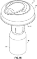
- Spike member 122 serves the purpose of piercing a fluid container such as first vial 80 during assembly of vial access device 12 to first vial 80 as shown in Fig. 18 and also serves the purpose of piercing a fluid container such as second vial 90 during assembly of vial access device 12 to second vial 90 as shown in Fig. 15 .
- connector 20 generally includes a first or proximal end 130; an opposing second or distal end 132; a membrane cavity 134 located at first end 130; a bottom protrusion 136 located at second end 132; and a locking groove 138.
- connector 20 comprises other connectors which are compatible with a closed system drug transfer device.
- connector 20 is attachable to inner housing 18 by cavity 114 of inner housing 18 receiving connector 20 and first groove cavity 116 and second groove cavity 118 also receiving respective bottom protrusions 136 of connector 20. In this manner, the engagement of bottom protrusions 136 of connector 20 within respective first groove cavity 116 and second groove cavity 118 secures connector 20 to inner housing 18 and prevents connector 20 from significant relative movement relative to inner housing 18 as shown in Figs. 4B and 4C .
- connection system 140 includes a connection element or connection system 140.
- connection system 140 comprises locking groove 138.
- Locking groove 138 of connector 20 is engageable with a portion of an injector or injector adapter, e.g., injector 27 ( Figs. 20 and 21 ), to secure the injector 27 to connector 20 and vial access device 12.
- Connection system 140 of connector 20 provides a secured attachment between vial access device 12 and an injector such that significant relative movement between the injector and vial access device 12 is prevented and such that a cannula of the injector is maintained in a leak-proof sealing system throughout the process of engaging the cannula with a vial.
- the connector 20 may be embodied as any other suitable connection arrangement.
- membrane cavity 134 of connector 20 may contain a pierceable barrier member.
- a pierceable barrier member provides for a liquid and gas tight seal between a piercing member and the pierceable barrier member during fluid transfer to minimize leakage and thereby prevent exposure of hazardous medicaments to a user.
- the pierceable barrier member provides a self-sealing seal that, with vial access device 12 attached to a vial, provides a leak-proof seal preventing any substance contained within the vial chamber from being exposed to a health care provider reconstituting, transporting, or administering a drug using system 10.
- the pierceable barrier member comprises a resilient material.
- the pierceable barrier member is preferably a unitary device molded of any flexible, elastomeric material conventionally used for fabricating gas-proof closures.
- the pierceable barrier member may be formed of a natural rubber material, polyurethane elastomers, butyl rubbers, or similar materials. It is contemplated that the pierceable barrier member is formed of a material having a Shore A hardness of approximately 10 to 50.
- the pierceable barrier member can have other material hardness values that would provide an appropriate self-sealing material to provide a leak-proof seal with a vial septum of a vial and an injector, thereby preventing any liquid or medication residue from being exposed to a health care provider reconstituting, transporting, or administering a drug using system 10.
- FIGs. 9A and 9B illustrate another exemplary aspect of a connector of the present disclosure.
- the aspect illustrated in Figs. 9A and 9B includes similar components to the aspect illustrated in Figs. 8A-8G , and the similar components are denoted by a reference number followed by the letter A.
- these similar components and the similar steps of using connector 20A will not all be discussed in conjunction with the aspect illustrated in Figs. 9A and 9B .
- connector 20A includes a bottom aperture 142.
- Connector 20A is attachable to inner housing 18 by cavity 114 of inner housing 18 receiving connector 20A and bottom aperture 142 of connector 20A being locked over a protrusion on inner housing 18 to secure connector 20A to inner housing 18 and prevent connector 20A from significant relative movement relative to inner housing 18.
- top cap housing 22 generally includes a first or proximal end 150; an opposing second or distal end 152; a sidewall 154 extending between first end 150 and second end 152 and defining a connector receiving portion 156; and a handle portion 158.
- top cap housing 22 comprises other covers which are compatible with a closed system drug transfer device.
- top cap housing 22 may be embodied as any other suitable cover arrangement.
- top cap housing 22 is attachable to first end 100 of inner housing 18 by cavity 114 of inner housing 18 receiving top cap housing 22 by an interference fit between the exterior wall surface of sidewall 154 of top cap housing 22 and the interior wall surface of first region wall 113 as shown in Figs. 4B and 4C .
- first end 130 of connector 20 is received within connector receiving portion 156 of top cap housing 22 as shown in Figs. 4B and 4C .
- top cap housing 22 With top cap housing 22 properly secured to inner housing 18 as described above, the top cap housing seals vial access device 12, i.e., top cap housing 22 provides a substantially impermeable enclosure with respect to vial access device 12, provides a leak prevention and protection enclosure, protects the contents of vial access device 12, and/or maintains a sealed, sterilized environment within vial access device 12.
- Top cap housing 22 provides a sufficient seal at a range of temperatures, pressures, and humidity levels.
- pressure equalization system 24 includes a pressure equalization housing 160 and an expandable balloon 162 which includes an expansion chamber 164.
- Pressure equalization housing 160 also includes a flange portion 166.
- Expandable balloon 162 includes a variable volume.
- Pressure equalization housing 160 comprises a relatively rigid material and expandable balloon 162 comprises a relatively flexible material.
- expandable balloon 162 comprises a thin, transparent plastic film that is attached to pressure equalization housing 160 in a gastight manner.
- expandable balloon 162 is designed as a bellow which is compressible and extendable and thus the volume of the expansion chamber 164 of expandable balloon 162 can thereby be increased and decreased.
- pressure equalization housing 160 extends radially around inner housing 18 and expandable balloon 162 extends radially around inner housing 18.
- expandable balloon 162 comprises a toroidal shape.
- pressure equalization system 24 comprises other pressure equalization systems which are compatible with a closed system drug transfer device.
- Pressure equalization housing 160 provides a barrier wall member that protects expandable balloon 162 from being torn during engagement of a cannula with a vial, during transfer of a substance from a vial chamber to a barrel chamber, e.g., a barrel assembly 28 ( Figs. 20-23 ), via the cannula, and during disengagement of the cannula from the vial.
- the vial access device 12 is balanced such that a center of mass is positioned at about a longitudinal axis of vial access device 12.
- expandable balloon 162 extends three-hundred sixty degrees (360°) radially around inner housing 18 of vial access device 12.
- a portion of expandable balloon 162 is not covered by pressure equalization housing 160. In this manner, expandable balloon 162 is capable of expanding in an axial direction.
- pressure equalization housing 160 is received within outer housing 16 such that first shoulder 44 of outer housing 16 provides an engagement surface with flange portion 166 of pressure equalization housing 160 as shown in Figs. 4B and 4C .
- pressure equalization housing 160 and outer housing 16 are a single integral component.
- pressure equalization housing 160 and outer housing 16 are separate components and pressure equalization housing 160 is attachable to outer housing 16 such that significant relative movement between pressure equalization housing 160 and outer housing 16 is prevented.
- a pressure normalization channel extends from piercing tip 124 to expandable balloon 162.
- the pressure normalization channel is arranged to provide gas communication between the expandable balloon 162 and the interior of a vial when vial access device 12 is connected to a vial.
- the pressure normalization channel may be embodied as any suitable pressure normalization channel arrangement.
- a syringe, cannula assembly, or injector e.g., injector 27 ( Figs. 20 and 21 )
- injector 27 e.g., injector 27
- the pressure equalization system 24 may be embodied as any other suitable pressure equalization system arrangement.
- pressure equalization system 24 When preparing and administering drugs, care has to be taken to minimize, or preferably eliminate, the risk of exposing people, such as medical and pharmacological personnel, to toxic substances. Some drugs must be dissolved or diluted before they are administered, which involves transferring a solvent from one container to a sealed vial containing the drug in powder or liquid form, by means of a needle, for example. Drugs may be inadvertently released into the atmosphere in gas form or by way of aerosolization during the withdrawal of the needle from the vial and while the needle is inside the vial if any differential pressure exists between the interior of the vial and surrounding atmosphere.
- Vial access device 12 of the present disclosure eliminates this problem by using pressure equalization system 24 of vial access device 12 that may be attached to a vial during the preparation of drugs.
- the pressure equalization system 24 includes an expandable balloon 162 which is in communication with the interior of a vial which ensures that neither an increased pressure nor a vacuum can occur inside the vial, e.g., first vial 80 ( Figs. 16-19 ) or second vial 90 ( Figs. 13-15 ), when gas or liquid is injected into or withdrawn from the vial.
- the expandable balloon 162 may be filled with cleaned or sterilized air prior to its use to ensure that the contents of the vial do not become contaminated with air-borne particles such as dust, pollen, mold, bacteria, or other undesirable substances.
- the vial access device 12 may be secured to a cannula of injector 27 which in turn can be connected to a fluid container, such as barrel assembly 28, and the vial access device 12 can also be assembled via its vial connection elements 52 with a second fluid container, such as a first vial 80.
- a second fluid container such as a first vial 80.
- First vial 80 may be a standard drug vial of any type having an open head portion covered by a pierceable septum of an elastomeric material.
- the plurality of vial grip members 54 fixedly connect vial access device 12 to the first vial 80 as the hook protrusions 56 of vial grip members 54 engage the corresponding flange 87 on first vial 80 as shown in Fig. 18 .
- a user is able to insert fluid into the first vial 80, or optionally, to retract fluid from the first vial 80.
- the pressure equalization system 24 of vial access device 12 permits pressure equalization between the first vial 80 and the expandable balloon 162.
- the pressure normalization channel of the pressure equalization system 24 normalizes the pressure inside the first vial 80 by relieving the pressure inside the first vial 80 to the expansion chamber 164 of the expandable balloon 162 as shown in Fig. 19 .
- adapter 14 generally includes a first or proximal end 170; an opposing second or distal end 172; guide channels 174; a vial connection element 176 comprising adapter vial grip members 178, hook protrusions 180, and angled walls 182; and locking members or outer housing engagement portions 184.
- Adapter 14 is sized and shaped for movement within the elongate aperture 50 of vial access housing 26 and the adapter 14 is transitionable between a first position ( Figs.
- a vial connection element 176 is disposed at second end 172 of adapter 14.
- vial connection element 176 includes a plurality of adapter vial grip members 178 having hook protrusions 180 and angled walls 182.
- adapter vial grip members 178 are elastically deformable.
- Adapter vial grip members 178 are attachable to a second vial 90 to secure vial access device 12 to the second vial 90 via adapter 14.
- vial access device 12 and adapter 14 provide a system 10 that is capable of accommodating a plurality of vials having different sizes, e.g., first vial 80 having first vial size 81 and second vial 90 having second vial size 91.
- Each adapter vial grip member 178 includes a hook protrusion 180 arranged to engage a corresponding flange 97 on a container such as second vial 90 as shown in Fig. 15 .
- Vial connection element 176 of adapter 14 may be dimensioned to be attached to containers of any size and volume.
- vial connection element 176 of adapter 14 may include other connection mechanisms for securing adapter 14 and vial access device 12 to second vial 90 such as a threaded portion, a snap fit mechanism, locking tabs, or other similar mechanism.
- Each adapter vial grip member 178 includes an angled wall 182 arranged to provide a lead-in surface to center and align vial access device 12 on a vial.
- vial access device 12 and adapter 14 provide a system 10 that is capable of accommodating a plurality of vials having different sizes, e.g., first vial 80 having first vial size 81 and second vial 90 having second vial size 91.
- vial access device 12 and adapter 14 are compatible with a first vial 80 comprising a 20 mm vial and a second vial 90 comprising a 13 mm vial.
- vial access device 12 and adapter 14 are compatible with a first vial 80 comprising a 28 mm vial and a second vial 90 comprising a 20 mm vial.
- vial access device 12 and adapter 14 are compatible with a first vial 80 comprising a 32 mm vial and a second vial 90 comprising a 28 mm vial. In other aspects, it is envisioned that vial access device 12 and adapter 14 are compatible with a first vial 80 comprising other vial sizes and a second vial 90 comprising other vial sizes, wherein the second vial size is less than the first vial size.
- guide channels 174 of adapter 14 are configured to engage corresponding guiding protrusions 71 within elongate aperture 50 of outer housing 16.
- the corresponding guiding surfaces of adapter 14 and outer housing 16 provide a guided, controlled movement of adapter 14 between the first position ( Figs. 13-15 ) and the second position ( Figs. 16-18 ) and establish a secure attachment between the adapter 14 and the outer housing 16 as shown in Figs. 15 and 18 .
- locking members or outer housing engagement portions 184 of adapter 14 engage adapter engagement portions 68 which act as a physical barrier to prevent adapter 14 from being removed from within elongate aperture 50.
- Adapter 14 is sized for movement within elongate aperture 50 of vial access housing 26 and engagement of adapter engagement portions 68 with locking members 184 of adapter 14 prevents adapter 14 from being removed from elongate aperture 50.
- vial access device 12 and adapter 14 to provide a system 10 that is capable of accommodating a plurality of vials having different sizes, e.g., first vial 80 having first vial size 81 and second vial 90 having second vial size 91, will now be described.
- the adapter 14 is adjacent the aperture distal end 66 of the vial access housing 26 and the adapter 14 is attachable to the second vial 90 defining the second vial size 91 as described above.
- the spike member 122 is in fluid communication with vial chamber 96 of the second vial 90 as shown in Fig. 15 .
- system 10 With the vial access device 12 attached to the second vial 90 via the adapter 14, system 10 provides substantially leak-proof sealing and pressure equalization during engagement of a cannula of injector 27 with second vial 90 during transfer of a substance from vial chamber 96 to a barrel chamber of barrel assembly 28 via the cannula, and during disengagement of the cannula from the second vial 90.
- the leak-proof sealing of the system 10 substantially prevents leakage of both air and liquid during use of the system 10.
- System 10 is compatible with a needle and syringe assembly for accessing a medication contained within a vial for administering the medication to a patient.
- System 10 is also compatible to be used with a drug reconstitution system.
- the pressure equalization system 24 of vial access device 12 permits pressure equalization between the second vial 90 and the expandable balloon 162.
- the pressure normalization channel of the pressure equalization system 24 normalizes the pressure inside the second vial 90 by relieving the pressure inside the second vial 90 to the expansion chamber 164 of the expandable balloon 162 as shown in Fig. 19 .
- adapter 14 is sized and shaped for movement within the elongate aperture 50 of vial access housing 26 and the adapter 14 is transitionable between the first position ( Figs. 13-15 ) and the second position ( Figs. 16-18 ).
- the adapter 14 is adjacent the aperture proximal end 64 of the vial access housing 26 and the vial connection element 52 of the vial access device 12 is attachable to the first vial 80 as described above.
- the adapter 14 With the adapter 14 in the second position, the adapter 14 is disposed above the vial connection element 52 of the vial access device 12. In this manner, the adapter 14 is out of the way of the vial connection element 52 and the vial connection element 52 is attachable to the first vial 80.
- the spike member 122 is in fluid communication with vial chamber 86 of the first vial 80 as shown in Fig. 18 .
- system 10 With the vial access device 12 attached to the first vial 80, system 10 provides substantially leak-proof sealing and pressure equalization during engagement of a cannula of injector 27 with first vial 80, during transfer of a substance from vial chamber 86 to a barrel chamber of barrel assembly 28 via the cannula, and during disengagement of the cannula from the first vial 80.
- the leak-proof sealing of the system 10 substantially prevents leakage of both air and liquid during use of the system 10.
- System 10 is compatible with a needle and syringe assembly for accessing a medication contained within a vial for administering the medication to a patient.
- System 10 is also compatible to be used with a drug reconstitution system.
- the pressure equalization system 24 of vial access device 12 permits pressure equalization between the first vial 80 and the expandable balloon 162.
- the pressure normalization channel of the pressure equalization system 24 normalizes the pressure inside the first vial 80 by relieving the pressure inside the first vial 80 to the expansion chamber 164 of the expandable balloon 162 as shown in Fig. 19 .
- the vial access device 200 is similar to the vial access device 12 described above and will operate in the same manner.
- the vial access device 200 also includes an outer housing 216, inner housing 218, connector 220, top cap 222, a pressure equalization system 224, and a vial connection element 252.
- the outer housing 216 defines an annular space 226 that receives the pressure equalization system 224.
- the outer housing 216 also defines an inner space 228 that receives at least a portion of the inner housing 218 and the connector 220.
- the inner housing 218 includes a body 230 having a curved top surface and a cylindrical portion 232 extending in a longitudinal direction.
- the body 230 defines a central opening 234 that receives at least a portion of the top cap 222, the connector 220, and the vial connection element 252.
- the inner housing 218 is secured to the outer housing 216 by a snap-fit connection, although any other suitable securing arrangement may be utilized, such as adhesive, welding, etc.
- the top cap 222 includes a body 236 that defines a recessed portion 238 that receives a portion of the connector 220.
- the body 236 also includes an extension portion that defines a gripping surface 240 that is configured to facilitate grasping of the top cap 222 to remove the top cap 222 from the inner housing 218.
- the gripping surface 240 is shown as a recessed area of the body 230, although any other suitable arrangement may be utilized, such as a textured surface, a protrusion, dimples, etc.
- the top cap 222 is secured to the inner housing 218 via a snap-fit connection, although any other suitable securing arrangement may be utilized.
- the pressure equalization system 224 includes a toroidal balloon 242 positioned within annular space 226 of the outer housing 216. As discussed above in connection with the pressure equalization system 24, the balloon 242 is configured to expand and contract to change the volume defined by the balloon 242 and the outer housing 216. In particular, the balloon 242 is configured to expand axially outward from
- the connector 220 is positioned within inner space 228 of the outer housing 216 and the central opening 234 of the inner housing 218. As discussed above in connection with connector 20, the connector 220 is configured to mate with a mating connector or component.
- the connector 220 includes a body 244 defining a central passageway 246.
- a flange 248 extends radially outward from the body 244 of the connector 220.
- a membrane or septum 250 is positioned and secured at a proximal end of the connector 220 and closes the central passageway 246.
- the flange 248 abuts a ledge 254 defined by the outer housing 216 and defines an annular filter space 256 that receives an annular filter 258.
- the flange 248 may be secured to the outer housing 216 via snap-fit connection, although any other suitable securing arrangement may be utilized.
- the filter 258 is hydrophobic filter that prevents liquid flow, but allows air to flow through during operations of the pressure equalization system 224.
- the vial connection element 252 is similar to the vial connection element 52 described above.
- the vial connection element 252 includes a body 260 having vial grip members 262 extending from the 260.
- the vial connection element 252 is configured to be secured to a vial thereby securing the vial access device 200 to the vial.
- the body 260 of the vial connection element 252 is cylindrical and received within the central passageway 246 of the connector 220.
- the body 260 defines a central passageway 264 that is aligned with the central passageway 246 of the connector 220.
- the vial connection element 252 includes a spike member 266 that is configured to puncture a septum of vial as discussed above in connection with system 10.
- the spike member 262 defines a fluid passageway 268 in fluid communication with the central passageways 246, 264 of the connector 220 and the vial connection element 252.
- the spike member 262 also defines a vent passageway 270 in fluid communication with the filter space 256 and the annular space 226 of the outer housing 216.
- the fluid passageway 268 is configured to facilitate the transfer of fluids to and from a vial to a mating device connected to the connector 220.
- the vent passageway 270 is configured to cooperate with the pressure equalization system 224, as discussed above in connection with system 10, to prevent a vial from being pressurized or depressurized during the transfer of contents to and from the vial.
- the filter 258 prevents the passage of liquids into the filter space 256 and into the annular space 226.
- an O-ring 272 may be positioned between the connector 220 and the vial connection element 252 where the connector 220 and the vial connection element 252 are joined and where the central passageways 246, 264 come into alignment.
- the vial access device 200 also includes a sleeve member 274 positioned over the spike member 266, which prevents leakage during fluid transfer when longer openings are used for the spike member 266 to optimize evacuation of the vial.
- the connector 220 may be embodied as any other suitable connection arrangement.
- the vial access device 200 may be provided with a packaging arrangement 208.
- the packaging arrangement 208 holds the vial access device 200 and maintains sterility prior to use, but can also be used to hold the vial access device 200 while connecting the vial access device 200 onto a container, such as a vial.
- Fig. 31 shows a configuration without the top cap 222 and where a portion of the packaging arrangement 208 engages the inner housing 218.
- the vial access device 200 is shown in use with a syringe adapter 210 and the vial 80.
- the syringe adapter 210 may be the syringe adapter and system noted above in connection with connector 20.
- the syringe adapter 210 cooperates with the connector 220 to facilitate the sealed transfer of substances between the vial 80 and a syringe (not shown) connected to the syringe adapter 210.
- the vial access device 300 is similar to the vial access device 12 described above and will operate in the same manner.
- the vial access device 300 includes a connector 20, a pressure equalization system 24, a connection element 52, and a spike member 122.
- the vial access device 300 also includes the sleeve member 274 discussed above in connection with the vial access device 200.
- the pressure equalization system 24 shown in Figs. 36-38 is generally rectangular.
- the vial access device 400 is similar to the vial access device 300 described above and will operate in the same manner as described in connection with vial access device 12.
- the vial access device 400 has a pressure equalization system that is substantially spherical.
Landscapes
- Health & Medical Sciences (AREA)
- Pharmacology & Pharmacy (AREA)
- Life Sciences & Earth Sciences (AREA)
- Animal Behavior & Ethology (AREA)
- General Health & Medical Sciences (AREA)
- Public Health (AREA)
- Veterinary Medicine (AREA)
- Physics & Mathematics (AREA)
- Fluid Mechanics (AREA)
- Medical Preparation Storing Or Oral Administration Devices (AREA)
Applications Claiming Priority (3)
| Application Number | Priority Date | Filing Date | Title |
|---|---|---|---|
| US201461982039P | 2014-04-21 | 2014-04-21 | |
| EP15719583.5A EP3134055B1 (fr) | 2014-04-21 | 2015-04-21 | Système avec adaptateur pour transfert de fluides en circuit fermé |
| PCT/US2015/026892 WO2015164385A1 (fr) | 2014-04-21 | 2015-04-21 | Système avec adaptateur pour transfert de fluides en circuit fermé |
Related Parent Applications (1)
| Application Number | Title | Priority Date | Filing Date |
|---|---|---|---|
| EP15719583.5A Division EP3134055B1 (fr) | 2014-04-21 | 2015-04-21 | Système avec adaptateur pour transfert de fluides en circuit fermé |
Publications (1)
| Publication Number | Publication Date |
|---|---|
| EP3398583A1 true EP3398583A1 (fr) | 2018-11-07 |
Family
ID=53016800
Family Applications (2)
| Application Number | Title | Priority Date | Filing Date |
|---|---|---|---|
| EP15719583.5A Active EP3134055B1 (fr) | 2014-04-21 | 2015-04-21 | Système avec adaptateur pour transfert de fluides en circuit fermé |
| EP18175946.5A Pending EP3398583A1 (fr) | 2014-04-21 | 2015-04-21 | Système comportant un adaptateur pour le transfert fermé de fluides |
Family Applications Before (1)
| Application Number | Title | Priority Date | Filing Date |
|---|---|---|---|
| EP15719583.5A Active EP3134055B1 (fr) | 2014-04-21 | 2015-04-21 | Système avec adaptateur pour transfert de fluides en circuit fermé |
Country Status (8)
| Country | Link |
|---|---|
| US (2) | US9980878B2 (fr) |
| EP (2) | EP3134055B1 (fr) |
| JP (2) | JP6355758B2 (fr) |
| CN (2) | CN106413662B (fr) |
| CA (1) | CA2946562C (fr) |
| ES (1) | ES2688366T3 (fr) |
| IL (2) | IL248416B (fr) |
| WO (1) | WO2015164385A1 (fr) |
Families Citing this family (43)
| Publication number | Priority date | Publication date | Assignee | Title |
|---|---|---|---|---|
| US7547300B2 (en) | 2006-04-12 | 2009-06-16 | Icu Medical, Inc. | Vial adaptor for regulating pressure |
| WO2010022095A1 (fr) | 2008-08-20 | 2010-02-25 | Icu Medical, Inc. | Adaptateurs de flacons anti-reflux |
| CA2768985C (fr) | 2009-07-29 | 2020-03-10 | Icu Medical, Inc. | Dispositifs de transfert de fluides et procedes d'utilisation |
| US10076272B2 (en) | 2011-04-26 | 2018-09-18 | Velano Vascular, Inc. | Systems and methods for phlebotomy through a peripheral IV catheter |
| US8366685B2 (en) | 2011-04-26 | 2013-02-05 | Creative Vascular, Llc | Systems and methods for phlebotomy through a peripheral IV catheter |
| ES2934668T3 (es) | 2011-08-18 | 2023-02-23 | Icu Medical Inc | Adaptadores de vial de regulación de presión |
| KR20140125781A (ko) | 2012-01-13 | 2014-10-29 | 아이씨유 메디칼 인코퍼레이티드 | 압력 조절 바이알 어댑터 및 방법 |
| WO2013142618A1 (fr) | 2012-03-22 | 2013-09-26 | Icu Medical, Inc. | Adaptateurs de flacon à régulation de pression |
| CA2931983C (fr) | 2012-11-30 | 2021-12-07 | Magnolia Medical Technologies, Inc. | Mecanisme de deviation de fluide par une seringue pour l'echantillonnage de liquide organique |
| US9089475B2 (en) | 2013-01-23 | 2015-07-28 | Icu Medical, Inc. | Pressure-regulating vial adaptors |
| DK2948125T3 (da) | 2013-01-23 | 2019-08-19 | Icu Medical Inc | Trykregulerende hætteglasadaptorer |
| EP3021814A4 (fr) | 2013-07-19 | 2017-08-09 | ICU Medical, Inc. | Systèmes et procédés de transfert de fluides à pression régulée |
| WO2015077184A1 (fr) | 2013-11-25 | 2015-05-28 | Icu Medical, Inc. | Procédés et système pour remplir des sacs pour perfusion intraveineuse d'un fluide thérapeutique |
| WO2015134431A1 (fr) | 2014-03-03 | 2015-09-11 | Magnolia Medical Technologies, Inc. | Appareil et procédés de désinfection d'un récipient à échantillons |
| CA2946562C (fr) * | 2014-04-21 | 2019-03-26 | Becton Dickinson and Company Limited | Systeme avec adaptateur pour transfert de fluides en circuit ferme |
| EP3157491B1 (fr) | 2014-06-20 | 2022-06-22 | ICU Medical, Inc. | Adaptateurs pour flacons destinés à réguler la pression |
| US11234626B2 (en) | 2015-06-12 | 2022-02-01 | Magnolia Medical Technologies, Inc. | Devices and methods for syringe-based fluid transfer for bodily-fluid sampling |
| EP4249119A3 (fr) | 2015-09-03 | 2023-11-29 | Magnolia Medical Technologies, Inc. | Système de maintien de la stérilité d'un récipient d'échantillon |
| AU2016365335B2 (en) | 2015-12-04 | 2021-10-21 | Icu Medical, Inc. | Systems methods and components for transferring medical fluids |
| JP2019503256A (ja) | 2016-01-29 | 2019-02-07 | アイシーユー・メディカル・インコーポレーテッド | 圧力調節バイアルアダプタ |
| USD851745S1 (en) | 2016-07-19 | 2019-06-18 | Icu Medical, Inc. | Medical fluid transfer system |
| WO2018022640A1 (fr) | 2016-07-25 | 2018-02-01 | Icu Medical, Inc. | Systèmes, procédés et composants pour piéger des bulles d'air dans des modules et des systèmes de transfert de fluide médical. |
| EP3518860A4 (fr) | 2016-09-30 | 2020-06-10 | ICU Medical, Inc. | Dispositifs et procédés d'accès à un flacon à régulation de pression |
| US11033459B2 (en) * | 2016-12-13 | 2021-06-15 | Shire Human Genetic Therapies, Inc. | Modular vial adapter |
| WO2018136359A1 (fr) | 2017-01-17 | 2018-07-26 | Becton Dickinson and Company Limited | Adaptateur de seringue |
| WO2018136357A1 (fr) | 2017-01-17 | 2018-07-26 | Becton Dickinson and Company Limited | Adaptateur de seringue à capuchon |
| JP7296881B2 (ja) | 2017-01-17 | 2023-06-23 | ベクトン ディキンソン アンド カンパニー リミテッド | 流体の閉鎖式移送のためのシステム用コネクタ |
| CA3050461A1 (fr) | 2017-01-17 | 2018-07-26 | Becton Dickinson and Company Limited | Adaptateur pour seringue pour transfert de fluides en circuit ferme |
| EP4059556A1 (fr) | 2017-03-21 | 2022-09-21 | Velano Vascular, Inc. | Procédés de commande de la taille d'un dispositif de cathéter |
| CN114470485A (zh) | 2017-03-21 | 2022-05-13 | 威蓝诺血管股份有限公司 | 通过已放置的外周静脉导管进行流体输送的装置和方法 |
| CA3082060A1 (fr) * | 2017-11-10 | 2019-05-16 | Simplivia Healthcare Ltd. | Adaptateur de flacon avec boitier |
| CA3090905C (fr) * | 2018-03-20 | 2022-12-13 | Becton Dickinson and Company Limited | Dispositif de raccordement pour transfert de fluides en circuit ferme |
| USD877900S1 (en) | 2018-04-04 | 2020-03-10 | Becton Dickinson and Company Limited | Medical infusion adapter |
| USD908872S1 (en) | 2018-04-04 | 2021-01-26 | Becton Dickinson and Company Limited | Medical vial access device |
| USD888945S1 (en) | 2018-04-04 | 2020-06-30 | Becton Dickinson and Company Limited | Medical connector |
| USD873996S1 (en) | 2018-04-04 | 2020-01-28 | Becton Dickinson and Company Limited | Medical syringe adapter |
| US11224555B2 (en) | 2018-04-23 | 2022-01-18 | Hospira, Inc. | Access and vapor containment system for a drug vial and method of making and using same |
| FR3084582B1 (fr) * | 2018-08-01 | 2023-10-27 | Aguettant Lab | Dispositif de connexion configure pour connecter un recipient a un flacon |
| EP3846767A4 (fr) * | 2018-09-07 | 2022-05-25 | Becton, Dickinson and Company | Ensemble seringue et élément adaptateur |
| JP2022545801A (ja) | 2019-08-20 | 2022-10-31 | ベラノ バスキュラー,インコーポレイテッド | 伸長型カテーテルを有する流体移送装置とその使用方法 |
| US11590057B2 (en) | 2020-04-03 | 2023-02-28 | Icu Medical, Inc. | Systems, methods, and components for transferring medical fluids |
| DE102020210629A1 (de) * | 2020-08-20 | 2022-02-24 | B. Braun Melsungen Aktiengesellschaft | Filtersystem für ein geschlossenes Fluidtransfersystem mit Druckausgleich |
| CA3197752A1 (fr) | 2020-11-26 | 2022-06-02 | Avia Vascular, Llc | Dispositifs, systemes et procedes de prelevement sanguin |
Citations (3)
| Publication number | Priority date | Publication date | Assignee | Title |
|---|---|---|---|---|
| WO1984004672A1 (fr) * | 1983-05-20 | 1984-12-06 | Bengt Gustavsson | Dispositif d'equilibrage de pression pour recipients scelles |
| US20100147402A1 (en) * | 2008-12-15 | 2010-06-17 | Carmel Pharma Ab | Connector Device |
| US20120179129A1 (en) * | 2009-12-04 | 2012-07-12 | Terumo Kabushiki Kaisha | Vial adapter |
Family Cites Families (136)
| Publication number | Priority date | Publication date | Assignee | Title |
|---|---|---|---|---|
| US4436125A (en) | 1982-03-17 | 1984-03-13 | Colder Products Company | Quick connect coupling |
| NZ207354A (en) | 1983-05-20 | 1988-02-29 | Bengt Gustavsson | Device for transferring fluid without the release of droplets |
| EP0331680B1 (fr) | 1986-11-06 | 1991-09-04 | Bengt Gustavsson | Recipient servant a stocker ou a recueillir des substances fluides et seches |
| US5334188A (en) | 1987-12-07 | 1994-08-02 | Nissho Corporation | Connector with injection site |
| US5052725A (en) | 1989-03-13 | 1991-10-01 | Colder Products Company | Two piece molded female coupling |
| US5104158A (en) | 1989-03-13 | 1992-04-14 | Colder Products Company | Two piece molded female coupling |
| US5122129A (en) | 1990-05-09 | 1992-06-16 | Olson Donald J | Sampler coupler device useful in the medical arts |
| DE9105229U1 (fr) | 1991-04-27 | 1991-06-13 | B. Braun Melsungen Ag, 3508 Melsungen, De | |
| ES2215359T3 (es) | 1991-12-18 | 2004-10-01 | Icu Medical, Inc. | Procedimiento de transferencia de fluido. |
| SE9203659L (sv) | 1992-12-04 | 1994-02-14 | Dicamed Ab | Ventilanordning för aseptisk injicering och uttag av medicinsk vätska i/ur behållare samt dess användning |
| US5478328A (en) | 1992-05-22 | 1995-12-26 | Silverman; David G. | Methods of minimizing disease transmission by used hypodermic needles, and hypodermic needles adapted for carrying out the method |
| GB9211912D0 (en) | 1992-06-04 | 1992-07-15 | Drg Flexpak Ltd | Vial connector system |
| US5290254A (en) | 1992-11-16 | 1994-03-01 | Vaillancourt Vincent L | Shielded cannula assembly |
| US5509911A (en) | 1992-11-27 | 1996-04-23 | Maxxim Medical, Inc. | Rotating adapter for a catheterization system |
| WO1994023775A1 (fr) | 1993-03-23 | 1994-10-27 | Abbott Laboratories | Collier de retenue pour raccord de canule |
| US5280876A (en) | 1993-03-25 | 1994-01-25 | Roger Atkins | Limited restriction quick disconnect valve |
| US5395348A (en) | 1993-05-04 | 1995-03-07 | Symbiosis Corporation | Medical intravenous administration line connectors |
| US5360011A (en) | 1993-07-13 | 1994-11-01 | Mccallister Teresa D | Blood sample collection |
| US5472430A (en) | 1993-08-18 | 1995-12-05 | Vlv Associates | Protected needle assembly |
| US5609584A (en) | 1994-05-18 | 1997-03-11 | Gettig Technologies, Inc. | Adaptor system for use with a syringe |
| US5487728A (en) | 1994-05-19 | 1996-01-30 | Vaillancourt; Vincent L. | Connector assembly |
| PT771184E (pt) | 1994-06-24 | 2002-11-29 | Icu Medical Inc | Dispositivo de transferencia de fluidos e metodo de utilizacao |
| US5545152A (en) | 1994-10-28 | 1996-08-13 | Minimed Inc. | Quick-connect coupling for a medication infusion system |
| US5607392A (en) | 1995-01-13 | 1997-03-04 | Ryder International Corporation | Fixed needle connector for IV assembly and method of assembling |
| US5647845A (en) | 1995-02-01 | 1997-07-15 | Habley Medical Technology Corporation | Generic intravenous infusion system |
| IL114960A0 (en) | 1995-03-20 | 1995-12-08 | Medimop Medical Projects Ltd | Flow control device |
| SE509950C2 (sv) | 1995-05-02 | 1999-03-29 | Carmel Pharma Ab | Anordning för administrering av toxisk vätska |
| US5700248A (en) | 1995-12-15 | 1997-12-23 | Icu Medical, Inc. | Medical valve with tire seal |
| US5807347A (en) | 1995-12-21 | 1998-09-15 | Bonaldo; Jean M. | Medical valve element |
| US5897526A (en) | 1996-06-26 | 1999-04-27 | Vaillancourt; Vincent L. | Closed system medication administering system |
| US6221056B1 (en) | 1996-12-20 | 2001-04-24 | David G. Silverman | Strong diaphragm/safe needle units and components for transfer of fluids |
| US6089541A (en) | 1998-09-10 | 2000-07-18 | Halkey-Roberts Corporation | Valve having a valve body and a deformable stem therein |
| IT236233Y1 (it) | 1997-11-26 | 2000-08-08 | Eurospital S P A | Dispositivo per il collegamento di un contenitore di prodottofarmaceutico ad una sacca di prodotto liquido per effettuare il |
| US6071270A (en) | 1997-12-04 | 2000-06-06 | Baxter International Inc. | Sliding reconstitution device with seal |
| US6378714B1 (en) * | 1998-04-20 | 2002-04-30 | Becton Dickinson And Company | Transferset for vials and other medical containers |
| DE19828651C2 (de) | 1998-06-26 | 2000-07-13 | Fresenius Medical Care De Gmbh | Konnektorelement mit Verschlußteil für die Medizintechnik |
| US6358236B1 (en) | 1998-08-06 | 2002-03-19 | Baxter International Inc. | Device for reconstituting medicaments for injection |
| US6113583A (en) | 1998-09-15 | 2000-09-05 | Baxter International Inc. | Vial connecting device for a sliding reconstitution device for a diluent container |
| AR021220A1 (es) | 1998-09-15 | 2002-07-03 | Baxter Int | DISPOSITIVO DE CONEXIoN PARA ESTABLECER UNA COMUNICACIoN FLUíDA ENTRE UN PRIMER RECIPIENTE Y UN SEGUNDO RECIPIENTE. |
| US20020173748A1 (en) | 1998-10-29 | 2002-11-21 | Mcconnell Susan | Reservoir connector |
| CA2669175C (fr) | 1998-10-29 | 2014-01-28 | Medtronic Minimed, Inc. | Raccord pour reservoir |
| FR2789369B1 (fr) | 1999-02-10 | 2001-04-27 | Biodome | Dispositif de connexion entre un recipient et un contenant et ensemble pret a l'emploi comprenant un tel dispositif |
| US6544246B1 (en) | 2000-01-24 | 2003-04-08 | Bracco Diagnostics, Inc. | Vial access adapter and vial combination |
| US6139534A (en) | 2000-01-24 | 2000-10-31 | Bracco Diagnostics, Inc. | Vial access adapter |
| US6832994B2 (en) | 2000-01-24 | 2004-12-21 | Bracco Diagnostics Inc. | Table top drug dispensing vial access adapter |
| SE0001278L (sv) | 2000-04-06 | 2001-10-08 | Peter Unger Med P U Med Konsul | Sterilkoppling |
| JP4372310B2 (ja) | 2000-04-10 | 2009-11-25 | ニプロ株式会社 | 混注用アダプター |
| US6343629B1 (en) | 2000-06-02 | 2002-02-05 | Carmel Pharma Ab | Coupling device for coupling a vial connector to a drug vial |
| US6629958B1 (en) | 2000-06-07 | 2003-10-07 | Ronald P. Spinello | Leak sealing needle |
| SE517084C2 (sv) | 2000-08-10 | 2002-04-09 | Carmel Pharma Ab | Förfarande och anordningar vid aseptisk beredning |
| FR2819174B1 (fr) | 2001-01-08 | 2003-06-13 | Pierre Frezza | Ampoule pour le conditionnement et le transfert d'un liquide ou d'une poudre a usage medical dans un contenant |
| US6474375B2 (en) | 2001-02-02 | 2002-11-05 | Baxter International Inc. | Reconstitution device and method of use |
| US6656433B2 (en) | 2001-03-07 | 2003-12-02 | Churchill Medical Systems, Inc. | Vial access device for use with various size drug vials |
| US7004934B2 (en) | 2001-09-06 | 2006-02-28 | Vaillancourt Vincent L | Closed system connector assembly |
| US6715520B2 (en) | 2001-10-11 | 2004-04-06 | Carmel Pharma Ab | Method and assembly for fluid transfer |
| US6911025B2 (en) | 2002-01-25 | 2005-06-28 | Jms Co., Ltd. | Connector system for sterile connection |
| JP3972665B2 (ja) | 2002-01-25 | 2007-09-05 | 株式会社ジェイ・エム・エス | 無菌接続コネクタシステム |
| US6875205B2 (en) | 2002-02-08 | 2005-04-05 | Alaris Medical Systems, Inc. | Vial adapter having a needle-free valve for use with vial closures of different sizes |
| US7744581B2 (en) | 2002-04-08 | 2010-06-29 | Carmel Pharma Ab | Device and method for mixing medical fluids |
| US7867215B2 (en) | 2002-04-17 | 2011-01-11 | Carmel Pharma Ab | Method and device for fluid transfer in an infusion system |
| EP1499382B1 (fr) | 2002-04-26 | 2006-12-27 | GL Tool and Manufacturing Co. Inc. | Vanne |
| US7350535B2 (en) | 2002-04-26 | 2008-04-01 | Gl Tool And Manufacturing Co. Inc. | Valve |
| US8491563B2 (en) | 2002-07-09 | 2013-07-23 | Carmel Pharma Ab | Device for injecting medical substances |
| SE523001C2 (sv) | 2002-07-09 | 2004-03-23 | Carmel Pharma Ab | En kopplingsdel, en koppling, en infusionspåse, en infusionsanordning och ett förfarande för överföring av medicinska substanser |
| US7040598B2 (en) | 2003-05-14 | 2006-05-09 | Cardinal Health 303, Inc. | Self-sealing male connector |
| US20040249235A1 (en) | 2003-06-03 | 2004-12-09 | Connell Edward G. | Hazardous material handling system and method |
| GB0317175D0 (en) | 2003-07-23 | 2003-08-27 | Liversidge Barry P | Medical needle system |
| EP1649890B1 (fr) | 2003-07-31 | 2011-05-18 | JMS Co. Ltd. | Systeme de connecteur a usage medical |
| US7390321B2 (en) | 2003-09-18 | 2008-06-24 | Advanced Technology Materials, Inc. | Connection having laminar flow for the delivery of a substance |
| SI2463201T1 (sl) | 2003-10-30 | 2014-06-30 | Teva Medical Ltd. | Naprava za varno obdelavo zdravila |
| US20080287914A1 (en) | 2003-12-22 | 2008-11-20 | Philip Wyatt | Medicament administration apparatus |
| US7530546B2 (en) | 2004-01-13 | 2009-05-12 | Rymed Technologies, Inc. | Swabbable needle-free injection port valve system with zero fluid displacement |
| EP1787667A4 (fr) | 2004-08-04 | 2010-07-07 | Ajinomoto Kk | Aiguille de communication utilisee pour faire communiquer deux recipients ou plus |
| US7731678B2 (en) | 2004-10-13 | 2010-06-08 | Hyprotek, Inc. | Syringe devices and methods for mixing and administering medication |
| US20080045919A1 (en) | 2004-12-23 | 2008-02-21 | Bracco Research S.A. | Liquid Transfer Device for Medical Dispensing Containers |
| JP4647365B2 (ja) | 2005-03-31 | 2011-03-09 | 日本シャーウッド株式会社 | 医療用の接続器具 |
| WO2006124756A2 (fr) | 2005-05-13 | 2006-11-23 | Bob Rogers | Systeme de transfert de substance medicale |
| US7803140B2 (en) | 2005-07-06 | 2010-09-28 | Icu Medical, Inc. | Medical connector with closeable male luer |
| ES2496968T3 (es) | 2005-11-07 | 2014-09-22 | Industrie Borla Spa | Adaptador para frascos de manejo seguro de descarga |
| EP1797919A1 (fr) | 2005-12-16 | 2007-06-20 | Bracco Research S.A. | Dispositif pour le transfert de liquides pour récipient de distribution de médicaments |
| AT503142B1 (de) | 2006-01-18 | 2009-05-15 | Friedrich Ing Pipelka | Behälter zur einbringung zumindest eines unsterilen gefässes in einen sterilen bereich |
| US7547300B2 (en) | 2006-04-12 | 2009-06-16 | Icu Medical, Inc. | Vial adaptor for regulating pressure |
| US8257286B2 (en) | 2006-09-21 | 2012-09-04 | Tyco Healthcare Group Lp | Safety connector apparatus |
| US7857805B2 (en) | 2006-10-02 | 2010-12-28 | B. Braun Medical Inc. | Ratcheting luer lock connector |
| US8167863B2 (en) | 2006-10-16 | 2012-05-01 | Carefusion 303, Inc. | Vented vial adapter with filter for aerosol retention |
| US8105314B2 (en) | 2006-10-25 | 2012-01-31 | Icu Medical, Inc. | Medical connector |
| US7900659B2 (en) | 2006-12-19 | 2011-03-08 | Carefusion 303, Inc. | Pressure equalizing device for vial access |
| US7883499B2 (en) | 2007-03-09 | 2011-02-08 | Icu Medical, Inc. | Vial adaptors and vials for regulating pressure |
| US7942860B2 (en) | 2007-03-16 | 2011-05-17 | Carmel Pharma Ab | Piercing member protection device |
| US8196614B2 (en) | 2007-04-23 | 2012-06-12 | Plastmed Ltd. | Method and apparatus for contamination-free transfer of a hazardous drug |
| US7975733B2 (en) | 2007-05-08 | 2011-07-12 | Carmel Pharma Ab | Fluid transfer device |
| GB2451891A (en) | 2007-08-17 | 2009-02-18 | Univ Sheffield Hallam | Medical fluid connector with features to ensure correct coupling |
| JP2010538744A (ja) | 2007-09-18 | 2010-12-16 | メディモップ・メディカル・プロジェクツ・リミテッド | 薬剤混合注射装置 |
| WO2009090627A1 (fr) | 2008-01-17 | 2009-07-23 | Teva Medical Ltd. | Elément d'adaptation de seringue dans un système de mélange de médicaments |
| US8449521B2 (en) | 2008-02-06 | 2013-05-28 | Intravena, Llc | Methods for making and using a vial shielding convenience kit |
| FR2928539B1 (fr) | 2008-03-12 | 2012-02-24 | Vygon | Dispositif d'interfacage pour flacons a perforer a fins de preparations de liquides perfuses |
| US9039047B2 (en) | 2008-05-02 | 2015-05-26 | Terumo Kabushiki Kaisha | Connector assembly |
| US20110106046A1 (en) | 2008-05-02 | 2011-05-05 | Terumo Kabushiki Kaisha | Connector assembly |
| NZ589151A (en) | 2008-05-14 | 2012-08-31 | J & J Solutions Inc | Systems and methods for safe medicament transport |
| JP5495006B2 (ja) * | 2008-11-25 | 2014-05-21 | 株式会社ジェイ・エム・エス | コネクタ |
| US8512309B2 (en) | 2009-01-15 | 2013-08-20 | Teva Medical Ltd. | Vial adapter element |
| WO2010099000A2 (fr) | 2009-02-24 | 2010-09-02 | Teva Medical Ltd. | Ensemble adaptateur de flacon dans un système de mélange de médicament |
| US8454579B2 (en) | 2009-03-25 | 2013-06-04 | Icu Medical, Inc. | Medical connector with automatic valves and volume regulator |
| US8317741B2 (en) | 2009-05-26 | 2012-11-27 | Kraushaar Timothy Y | Apparatus and methods for administration of reconstituted medicament |
| MX2012000100A (es) | 2009-07-01 | 2012-04-02 | Fresenius Med Care Hldg Inc | Dispositivos de suministro de farmaco y sistemas y metodos relacionados. |
| US8277424B2 (en) | 2009-07-17 | 2012-10-02 | Pan Hsiu-Feng | Needle-less syringe adapter |
| CA2768985C (fr) | 2009-07-29 | 2020-03-10 | Icu Medical, Inc. | Dispositifs de transfert de fluides et procedes d'utilisation |
| CN102686266B (zh) | 2009-09-04 | 2015-06-17 | B.布劳恩梅尔松根股份公司 | 可选择性密封阳型无针连接器及相关方法 |
| EP2490957B1 (fr) | 2009-10-23 | 2016-11-23 | Amgen, Inc | Adaptateur de fiole et système |
| EP2332510B1 (fr) | 2009-12-09 | 2013-02-13 | F. Hoffmann-La Roche AG | Élément de connexion |
| FR2956326A1 (fr) | 2010-02-17 | 2011-08-19 | Vygon | Ensemble de connecteurs pour un circuit liquide |
| CA2794052C (fr) | 2010-03-22 | 2018-10-16 | Alex Yeung | Systeme de securite pour injection |
| US8790327B2 (en) | 2010-03-30 | 2014-07-29 | Terumo Kabushiki Kaisha | Connector and connector assembly |
| EP2959878B1 (fr) | 2010-05-27 | 2017-04-12 | J&J Solutions, Inc. | Système de transfert de fluide fermé |
| US20130072893A1 (en) | 2010-06-30 | 2013-03-21 | Terumo Kabushiki Kaisha | Connector and connector assembly |
| JPWO2012002314A1 (ja) | 2010-06-30 | 2013-08-22 | テルモ株式会社 | コネクタおよびコネクタ組立体 |
| CN102985050A (zh) | 2010-07-12 | 2013-03-20 | 株式会社Jms | 医疗用药液移送器 |
| US20130303994A1 (en) | 2010-11-22 | 2013-11-14 | Novartis Ag | Adapter |
| EP2462971A1 (fr) | 2010-12-13 | 2012-06-13 | Sanofi-Aventis Deutschland GmbH | Ensemble formant une aiguille pour dispositifs d'administration de médicaments |
| US8857470B2 (en) | 2011-01-25 | 2014-10-14 | Fresenius Kabi Deutschland Gmbh | Connection device for connecting a first reservoir with a second reservoir |
| JP2014511249A (ja) | 2011-03-04 | 2014-05-15 | デュオジェクト・メディカル・システムズ・インコーポレイテッド | 連結容易な移送システム |
| US20120265163A1 (en) | 2011-04-14 | 2012-10-18 | Marc Bunjiun Cheng | Coupling system to transfer material between containers |
| FR2975896B1 (fr) | 2011-06-06 | 2014-06-06 | Biocorp Rech Et Dev | Dispositif de connexion entre un recipient et un contenant, procede d'assemblage et d'utilisation d'un tel dispositif |
| ES2934668T3 (es) | 2011-08-18 | 2023-02-23 | Icu Medical Inc | Adaptadores de vial de regulación de presión |
| IL215699A0 (en) | 2011-10-11 | 2011-12-29 | Medimop Medical Projects Ltd | Liquid drug reconstitution assemblage for use with iv bag and drug vial |
| WO2013066779A1 (fr) | 2011-10-31 | 2013-05-10 | Ge Healthcare Limited | Dispositif de perçage et de remplissage |
| SG192311A1 (en) | 2012-02-02 | 2013-08-30 | Becton Dickinson Holdings Pte Ltd | Adaptor with injection device for coupling to a medical container |
| WO2013119823A1 (fr) * | 2012-02-07 | 2013-08-15 | Yukon Medical, Llc | Dispositif de transvasement équipé d'un filtre pour fluide |
| CN104244905B (zh) * | 2012-03-01 | 2019-06-04 | 贝克顿迪金森有限公司 | 压力平衡装置和储器 |
| US9808401B2 (en) | 2012-05-31 | 2017-11-07 | Kinki University | Exposure-preventing cap |
| EP2759285A1 (fr) * | 2013-01-28 | 2014-07-30 | Becton Dickinson France | Adaptateur pour couplage avec un récipient médical |
| AU2014213628B2 (en) | 2013-02-07 | 2016-07-14 | Equashield Medical Ltd. | Improvements to a closed drug transfer system |
| US10022301B2 (en) * | 2013-03-15 | 2018-07-17 | Becton Dickinson and Company Ltd. | Connection system for medical device components |
| IL226281A (en) | 2013-05-09 | 2017-01-31 | Kriheli Marino | Needle valve and connectors for use in fluid transfer devices |
| EP3027162B1 (fr) | 2013-08-02 | 2018-07-18 | J&J Solutions, Inc. D.B.A Corvida Medical | Systèmes et procédés permettant de mélanger et de transporter un médicament en toute sécurité |
| CA2946562C (fr) * | 2014-04-21 | 2019-03-26 | Becton Dickinson and Company Limited | Systeme avec adaptateur pour transfert de fluides en circuit ferme |
-
2015
- 2015-04-21 CA CA2946562A patent/CA2946562C/fr active Active
- 2015-04-21 EP EP15719583.5A patent/EP3134055B1/fr active Active
- 2015-04-21 WO PCT/US2015/026892 patent/WO2015164385A1/fr active Application Filing
- 2015-04-21 EP EP18175946.5A patent/EP3398583A1/fr active Pending
- 2015-04-21 JP JP2016563938A patent/JP6355758B2/ja active Active
- 2015-04-21 US US14/691,898 patent/US9980878B2/en active Active
- 2015-04-21 ES ES15719583.5T patent/ES2688366T3/es active Active
- 2015-04-21 CN CN201580028744.7A patent/CN106413662B/zh active Active
- 2015-04-21 CN CN201910111341.9A patent/CN109771280B/zh active Active
-
2016
- 2016-10-20 IL IL248416A patent/IL248416B/en active IP Right Grant
-
2018
- 2018-05-01 US US15/967,894 patent/US11045392B2/en active Active
- 2018-06-12 JP JP2018112098A patent/JP6840107B2/ja active Active
-
2020
- 2020-05-13 IL IL274629A patent/IL274629B/en unknown
Patent Citations (3)
| Publication number | Priority date | Publication date | Assignee | Title |
|---|---|---|---|---|
| WO1984004672A1 (fr) * | 1983-05-20 | 1984-12-06 | Bengt Gustavsson | Dispositif d'equilibrage de pression pour recipients scelles |
| US20100147402A1 (en) * | 2008-12-15 | 2010-06-17 | Carmel Pharma Ab | Connector Device |
| US20120179129A1 (en) * | 2009-12-04 | 2012-07-12 | Terumo Kabushiki Kaisha | Vial adapter |
Also Published As
| Publication number | Publication date |
|---|---|
| JP6840107B2 (ja) | 2021-03-10 |
| IL248416A0 (en) | 2016-11-30 |
| US20180243167A1 (en) | 2018-08-30 |
| WO2015164385A1 (fr) | 2015-10-29 |
| US11045392B2 (en) | 2021-06-29 |
| CA2946562A1 (fr) | 2015-10-29 |
| JP6355758B2 (ja) | 2018-07-11 |
| ES2688366T3 (es) | 2018-11-02 |
| CN109771280B (zh) | 2021-12-14 |
| EP3134055B1 (fr) | 2018-06-27 |
| CA2946562C (fr) | 2019-03-26 |
| EP3134055A1 (fr) | 2017-03-01 |
| IL248416B (en) | 2020-05-31 |
| CN106413662A (zh) | 2017-02-15 |
| US20150297456A1 (en) | 2015-10-22 |
| CN109771280A (zh) | 2019-05-21 |
| IL274629A (en) | 2020-06-30 |
| IL274629B (en) | 2022-02-01 |
| CN106413662B (zh) | 2019-03-12 |
| US9980878B2 (en) | 2018-05-29 |
| JP2018134557A (ja) | 2018-08-30 |
| JP2017513611A (ja) | 2017-06-01 |
Similar Documents
| Publication | Publication Date | Title |
|---|---|---|
| US11045392B2 (en) | System with adapter for closed transfer of fluids | |
| US11273101B2 (en) | System with adapter for closed transfer of fluids | |
| US11690788B2 (en) | System for closed transfer of fluids | |
| US11690786B2 (en) | Adapter for vial access device |
Legal Events
| Date | Code | Title | Description |
|---|---|---|---|
| PUAI | Public reference made under article 153(3) epc to a published international application that has entered the european phase |
Free format text: ORIGINAL CODE: 0009012 |
|
| STAA | Information on the status of an ep patent application or granted ep patent |
Free format text: STATUS: THE APPLICATION HAS BEEN PUBLISHED |
|
| AC | Divisional application: reference to earlier application |
Ref document number: 3134055 Country of ref document: EP Kind code of ref document: P |
|
| AK | Designated contracting states |
Kind code of ref document: A1 Designated state(s): AL AT BE BG CH CY CZ DE DK EE ES FI FR GB GR HR HU IE IS IT LI LT LU LV MC MK MT NL NO PL PT RO RS SE SI SK SM TR |
|
| STAA | Information on the status of an ep patent application or granted ep patent |
Free format text: STATUS: REQUEST FOR EXAMINATION WAS MADE |
|
| 17P | Request for examination filed |
Effective date: 20190503 |
|
| RBV | Designated contracting states (corrected) |
Designated state(s): AL AT BE BG CH CY CZ DE DK EE ES FI FR GB GR HR HU IE IS IT LI LT LU LV MC MK MT NL NO PL PT RO RS SE SI SK SM TR |
|
| STAA | Information on the status of an ep patent application or granted ep patent |
Free format text: STATUS: EXAMINATION IS IN PROGRESS |
|
| STAA | Information on the status of an ep patent application or granted ep patent |
Free format text: STATUS: EXAMINATION IS IN PROGRESS |
|
| 17Q | First examination report despatched |
Effective date: 20201208 |
|
| STAA | Information on the status of an ep patent application or granted ep patent |
Free format text: STATUS: EXAMINATION IS IN PROGRESS |