EP3398566A1 - Schubvorrichtung und fördersystem - Google Patents
Schubvorrichtung und fördersystem Download PDFInfo
- Publication number
- EP3398566A1 EP3398566A1 EP16880362.5A EP16880362A EP3398566A1 EP 3398566 A1 EP3398566 A1 EP 3398566A1 EP 16880362 A EP16880362 A EP 16880362A EP 3398566 A1 EP3398566 A1 EP 3398566A1
- Authority
- EP
- European Patent Office
- Prior art keywords
- main body
- steel cable
- distal end
- delivery system
- proximal end
- Prior art date
- Legal status (The legal status is an assumption and is not a legal conclusion. Google has not performed a legal analysis and makes no representation as to the accuracy of the status listed.)
- Pending
Links
Images



Classifications
-
- A—HUMAN NECESSITIES
- A61—MEDICAL OR VETERINARY SCIENCE; HYGIENE
- A61B—DIAGNOSIS; SURGERY; IDENTIFICATION
- A61B17/00—Surgical instruments, devices or methods
- A61B17/12—Surgical instruments, devices or methods for ligaturing or otherwise compressing tubular parts of the body, e.g. blood vessels or umbilical cord
- A61B17/12022—Occluding by internal devices, e.g. balloons or releasable wires
- A61B17/12027—Type of occlusion
- A61B17/12031—Type of occlusion complete occlusion
-
- A—HUMAN NECESSITIES
- A61—MEDICAL OR VETERINARY SCIENCE; HYGIENE
- A61B—DIAGNOSIS; SURGERY; IDENTIFICATION
- A61B17/00—Surgical instruments, devices or methods
- A61B17/12—Surgical instruments, devices or methods for ligaturing or otherwise compressing tubular parts of the body, e.g. blood vessels or umbilical cord
- A61B17/12022—Occluding by internal devices, e.g. balloons or releasable wires
-
- A—HUMAN NECESSITIES
- A61—MEDICAL OR VETERINARY SCIENCE; HYGIENE
- A61M—DEVICES FOR INTRODUCING MEDIA INTO, OR ONTO, THE BODY; DEVICES FOR TRANSDUCING BODY MEDIA OR FOR TAKING MEDIA FROM THE BODY; DEVICES FOR PRODUCING OR ENDING SLEEP OR STUPOR
- A61M39/00—Tubes, tube connectors, tube couplings, valves, access sites or the like, specially adapted for medical use
- A61M39/02—Access sites
- A61M39/06—Haemostasis valves, i.e. gaskets sealing around a needle, catheter or the like, closing on removal thereof
-
- A—HUMAN NECESSITIES
- A61—MEDICAL OR VETERINARY SCIENCE; HYGIENE
- A61B—DIAGNOSIS; SURGERY; IDENTIFICATION
- A61B17/00—Surgical instruments, devices or methods
- A61B17/12—Surgical instruments, devices or methods for ligaturing or otherwise compressing tubular parts of the body, e.g. blood vessels or umbilical cord
- A61B17/12022—Occluding by internal devices, e.g. balloons or releasable wires
- A61B17/12099—Occluding by internal devices, e.g. balloons or releasable wires characterised by the location of the occluder
- A61B17/12122—Occluding by internal devices, e.g. balloons or releasable wires characterised by the location of the occluder within the heart
-
- A—HUMAN NECESSITIES
- A61—MEDICAL OR VETERINARY SCIENCE; HYGIENE
- A61B—DIAGNOSIS; SURGERY; IDENTIFICATION
- A61B17/00—Surgical instruments, devices or methods
- A61B2017/00526—Methods of manufacturing
-
- A—HUMAN NECESSITIES
- A61—MEDICAL OR VETERINARY SCIENCE; HYGIENE
- A61B—DIAGNOSIS; SURGERY; IDENTIFICATION
- A61B17/00—Surgical instruments, devices or methods
- A61B2017/00526—Methods of manufacturing
- A61B2017/0053—Loading magazines or sutures into applying tools
-
- A—HUMAN NECESSITIES
- A61—MEDICAL OR VETERINARY SCIENCE; HYGIENE
- A61B—DIAGNOSIS; SURGERY; IDENTIFICATION
- A61B17/00—Surgical instruments, devices or methods
- A61B2017/00831—Material properties
- A61B2017/00862—Material properties elastic or resilient
-
- A—HUMAN NECESSITIES
- A61—MEDICAL OR VETERINARY SCIENCE; HYGIENE
- A61B—DIAGNOSIS; SURGERY; IDENTIFICATION
- A61B17/00—Surgical instruments, devices or methods
- A61B2017/00831—Material properties
- A61B2017/00955—Material properties thermoplastic
-
- A—HUMAN NECESSITIES
- A61—MEDICAL OR VETERINARY SCIENCE; HYGIENE
- A61B—DIAGNOSIS; SURGERY; IDENTIFICATION
- A61B17/00—Surgical instruments, devices or methods
- A61B17/12—Surgical instruments, devices or methods for ligaturing or otherwise compressing tubular parts of the body, e.g. blood vessels or umbilical cord
- A61B2017/12004—Surgical instruments, devices or methods for ligaturing or otherwise compressing tubular parts of the body, e.g. blood vessels or umbilical cord for haemostasis, for prevention of bleeding
-
- A—HUMAN NECESSITIES
- A61—MEDICAL OR VETERINARY SCIENCE; HYGIENE
- A61B—DIAGNOSIS; SURGERY; IDENTIFICATION
- A61B17/00—Surgical instruments, devices or methods
- A61B17/12—Surgical instruments, devices or methods for ligaturing or otherwise compressing tubular parts of the body, e.g. blood vessels or umbilical cord
- A61B17/12022—Occluding by internal devices, e.g. balloons or releasable wires
- A61B2017/1205—Introduction devices
Definitions
- the present application relates to the field of interventional medical instruments, and relates to a pushing apparatus for pushing the interventional medical instruments and a manufacturing method thereof, as well as a delivery system of the interventional medical instruments.
- Treating cardiovascular diseases by catheter intervention is a conventional therapy at the present, and it specifically means that various materials, devices and the like are put into parts such as the heart, an artery blood vessel and a vein of a human body via a catheter intervention therapy to treat the cardiovascular diseases.
- an interventional medical instrument such as an Atrial Septal Defect (ASD) occluder, a Ventricular Septal Defect (VSD) occluder, a Patent Ductus Arteriosus (PDA) occluder and a Patent Foramen Ovale (PFO) occluder, is placed via the catheter intervention method, and then reaches a defective part of the heart so as to occlude the defect to treat congenital heart diseases.
- ASD Atrial Septal Defect
- VSD Ventricular Septal Defect
- PDA Patent Ductus Arteriosus
- PFO Patent Foramen Ovale
- an occluder may be put into a left atrial appendage through a catheter intervention method to prevent a left atrial appendage thrombus caused by atrial fibrillation and avoid apoplexy caused by a fact that the thrombus goes up to a brain, or prevent systematic embolization caused by a fact that the thrombus reaches other portions of a body through a blood circulation system of a human body.
- a lung volume reduction device is delivered to a diseased position of a bronchus of the lung to treat pulmonary emphysema.
- the interventional medical device During delivery of the interventional medical device into the heart, the artery blood vessel, the vein, the left atrial appendage and the bronchus of the lung through a delivery system, the interventional medical device is generally pushed to a predetermined part through a flexible pushing steel cable, and then connection between the interventional medical device and the pushing steel cable is cut off to release the interventional medical device; and whether the release position of the interventional medical device is appropriate or not, whether the interventional medical device is poorly spread or not, and whether an operation effect is satisfactory or not are confirmed through radiography or ultrasonic.
- the present application provides a pushing apparatus for pushing an interventional medical device and a delivery system of the interventional medical device.
- a steel cable of the pushing apparatus of the present application has improved supporting properties; and during delivery of the interventional medical device, it is relatively difficult for the interventional medical device to deviate from a predetermined position, thus shortening the operation time, and reducing the operation risk of patients.
- the pushing apparatus and the delivery system of the present application are applicable to delivery of an interventional device, such as a left atrial appendage occluder, for a defect part with a complicated anatomical structure.
- an interventional device such as a left atrial appendage occluder
- the present application provides a pushing apparatus, including a steel cable.
- the steel cable includes a long-strip type steel cable main body, and also includes an overlay film arranged on the outer surface of the steel cable main body.
- the steel cable main body has a proximal end and a distal end which are opposite to each other.
- the proximal end of the overlay film is adjacent to the proximal end of the steel cable main body.
- the overlay film is made of a thermoplastic elastomer.
- thermoplastic elastomer includes polyether block amide or thermoplastic polyurethane.
- the length of the overlay film along the longitudinal central axis of the steel cable main body is equal to or less than half of the length of the steel cable main body.
- the steel cable main body includes a long-strip type inner core which is formed by twisting at least three strands of steel wires, and the overlay film is arranged on the outer surface of the inner core.
- the steel cable main body also includes a steel wire arranged on the inner core, and the overlay film is arranged on the outer surface of the steel wire.
- the present application further provides a delivery system which includes the pushing apparatus.
- the present application further provides a delivery system which includes a hemostasis apparatus.
- the hemostasis apparatus includes a hemostasis valve body having an inner cavity and a sealing member arranged in the inner cavity of the hemostasis valve body. A pore is formed in the sealing member. After the distal end of the steel cable main body penetrates through the hemostasis valve body from the distal end of the hemostasis valve body via the pore, the overlay film of the steel cable cooperates with the sealing member to isolate the distal end of the inner cavity of the hemostasis valve body from the outside world.
- the delivery system also includes a delivery sheath.
- the proximal end of the delivery sheath is connected with the distal end of the hemostasis apparatus, and an inner cavity of the delivery sheath is communicated with the inner cavity of the hemostasis apparatus.
- the delivery sheath includes a main body portion and a shaping portion.
- the main body portion is connected between the hemostasis apparatus and the shaping portion.
- the shaping portion includes a first shaping section; an included angle between the extending direction of the first shaping section and the extending direction of the main body portion ranges from 40 to 50 degrees; the extending direction of the first shaping section is a direction from the proximal end of the first shaping section to the distal end of the first shaping section; and the extending direction of the main body portion is a direction from the proximal end of the main body portion to the distal end of the main body portion.
- the shaping portion also includes a second shaping section.
- the first shaping section is connected between the main body portion and the second shaping section; an included angle between the extending direction of the second shaping section and a plane where the first shaping section and the main body portion are located ranges from 30 to 40 degrees; and the extending direction of the second shaping section is a direction from the proximal end of the second shaping section to the distal end of the second shaping section.
- the delivery system also includes an expansion tube; the outer diameter of the expansion tube is slightly less than the inner diameter of the delivery sheath; and the outer diameter of the head of the distal end of the expansion tube is gradually increased from the distal end to the proximal end.
- the expansion tube is provided with a shaping portion which is the same as the shaping portion of the delivery sheath in shape.
- the delivery system also includes a hollow loader connected between the delivery sheath and the hemostasis apparatus; and an inner cavity of the loader is communicated with the inner cavities of the delivery sheath and the hemostasis apparatus.
- the inner cavity of the hemostasis valve body has a conical section; the diameter of the proximal end of the conical section is greater than that of the distal end of the conical section; and the sealing member is adjacent to the proximal end of the conical section.
- the delivery system is used for delivering a left atrial appendage occluder; and the steel cable is detachably connected with the left atrial appendage occluder.
- the present application further provides a manufacturing method of a pushing apparatus, including:
- temperature for melting the overlap film tubular body ranges from 180 to 220 DEG C.
- the manufacturing method after the step of sleeving the steel cable main body with the overlap film tubular body, and before the step of melting the overlap film tubular body, the manufacturing method also includes a step of sleeving the overlap film tubular body with a heat shrink tubing.
- the melting point of the heat shrink tubing is lower than that of the overlap film tubular body.
- the manufacturing method also includes a step of removing the heat shrink tubing.
- the overlap film tubular body is made of a thermoplastic elastomer.
- thermoplastic elastomer includes polyether block amide or thermoplastic polyurethane.
- the present application has, at least, the advantages that the overlay film prepared from the thermoplastic elastomer is formed on the outer surface of the steel cable main body; the steel cable coated with the film may ensure that the distal end flexibly adapts to a bent blood vessel path, is higher in supporting property and pushing property, and is particularly suitable for a complicated vascular channel or treated part, such as left atrial appendage occlusion operation.
- the end close to an operator is regarded as a proximal end
- the end far away from the operator is regarded as a distal end.
- a delivery system 100 of Embodiment I is used for delivering an interventional medical device 200 to a diseased part and then releasing it.
- the interventional medical device 200 is a left atrial appendage occluder.
- the delivery system 100 delivers the interventional medical device 200 to a left atrial appendage and then releases it;
- the interventional medical device 200 includes two occluding disks and a layer of occluding film arranged inside one occluding disk; and the occluding disks are made of a material having a shape memory function, so that during use, they may be stretched into lines.
- the occluding film is made of a polytetrafluoroethylene material with good biocompatibility.
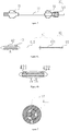
- the delivery system 100 includes a delivery apparatus 10, an expansion apparatus 20, a loading apparatus 30, a pushing apparatus 40 and a hemostasis apparatus 50.
- the distal end of the expansion apparatus 20 penetrates through the distal end of the delivery apparatus 10 to form an expansion assembly 300.
- the distal end of the expansion assembly 300 passes through the atrial septum from a femoral vein along a rail built by a guide wire (not shown in the figure), and reaches the left atrial appendage; and then the expansion apparatus 20 is removed, but the delivery apparatus 10 remains in the body, thus building a channel from outside to inside of the body
- the loading apparatus 30 is first connected between the hemostasis apparatus 50 and the delivery apparatus 10, and then the distal end of the pushing apparatus 40 penetrates through the hemostasis apparatus 50, the loading apparatus 30 and the delivery apparatus 10 in sequence, and then is detachably connected with the interventional medical device 200.
- the interventional medical device 200 is in threaded connection with the distal end of the pushing apparatus 40. It can be understood that the interventional medical device 200 also may be connected with the pushing apparatus 40 in other detachable ways, such as clamping connection, magnetic connection and pulling wire connection.
- the delivery system 100 may not include the loading apparatus 30; and the proximal end of a delivery sheath 11 is directly connected with the distal end of the hemostasis apparatus 50, and an inner cavity of the delivery sheath 11 is communicated with an inner cavity of the hemostasis apparatus 50.
- the delivery apparatus 10 includes the hollow delivery sheath 11 and a sheath connector 12 connected to the proximal end of the delivery sheath 11.
- the proximal end of the delivery sheath 11 is connected with the distal end of the loading apparatus 30, and the inner cavity of the delivery sheath 11 is communicated with an inner cavity of the loading apparatus 30.
- the delivery sheath 11 includes a main body portion 110 and a shaping portion 111.
- the main body portion 110 is connected between the hemostasis apparatus 50 and the shaping portion 111.
- the shaping portion 111 includes a first shaping section 1111; an included angle between the extending direction of the first shaping section 1111 and the extending direction of the main body portion 110 ranges from 40 to 50 degrees; the extending direction of the first shaping section 1111 is a direction from the proximal end of the first shaping section 1111 to the distal end of the first shaping section 1111; and the extending direction of the main body portion 110 is a direction from the proximal end of the main body portion 110 to the distal end of the main body portion 110.
- the shaping portion 111 also includes a second shaping section 1112.
- the first shaping section 1111 is connected between the main body portion 110 and the second shaping section 1112; an included angle between the extending direction of the second shaping section 1112 and a plane where the first shaping section 1111 and the main body portion 110 are located ranges from 30 to 40 degrees; and the extending direction of the second shaping section 1112 is a direction from the proximal end of the second shaping section 1112 to the distal end of the second shaping section 1112. Therefore, the shaping portion 111 is favorable for adapting to an anatomical structure of the left atrial appendage.
- the second shaping section 1112 also may be omitted according to an actual requirement as long as the shaping portion 111 having the first shaping section 1111 may conform to anatomical structures of different individuals and different predetermined interventional treatment positions.
- the sheath wall of the delivery sheath 11 is of a multilayer structure, and includes a polytetrafluoroethylene material layer, a stainless steel woven layer and a polyether block amide layer from inside to outside in sequence.
- the expansion apparatus 20 includes an expansion tube 21, a first connection screw cap 22 which is located at the proximal end of the expansion tube 21 and is connected with the proximal end of the expansion tube 21, and an expansion tube connector 23 located at the proximal end of the first connection screw cap 22.
- the expansion tube 21 may be arranged in the delivery sheath 11 in a penetrating manner, and is used for assisting the delivery sheath 11 along the guide wire in building a vascular path; and the expansion tube 21 is made of polyethylene.
- the outer diameter of the expansion tube 21 is slightly less than the inner diameter of the delivery sheath 11, so that the distal end of the expansion tube 21 may enter the delivery sheath 11 from the proximal end of the delivery sheath 11, and penetrates through the delivery sheath 11 from the distal end of the delivery sheath 11.
- the expansion tube 21 has a shaping portion which is the same as the shaping portion 111 of the delivery sheath 11 in shape.
- the outer diameter of the head of the distal end of the expansion tube 21 is gradually increased from the distal end to the proximal end.
- the first connection screw cap 22 may be in threaded connection with the proximal end of the delivery apparatus 10 to connect the delivery apparatus 10 with the expansion apparatus 20 to form the expansion assembly 300.
- the expansion tube connector 23 is used for limiting the proximal end of the expansion tube 21 to enter the delivery sheath 11.
- the loading apparatus 30 is connected between the delivery apparatus 10 and the hemostasis apparatus 50.
- the loading apparatus 30 includes a hollow loader 31.
- the proximal end of the loader 31 is connected with the distal end of the hemostasis apparatus 50, and the distal end of the loader 31 is connected with the proximal end of the delivery sheath 11 of the delivery apparatus 10.
- An inner cavity of the loader 31 may be communicated with the inner cavity of the hemostasis apparatus 50.
- the loading apparatus 30 also may include a loader front connector 32 connected to the distal end of the loader 31 and a loader rear connector 33 connected to the proximal end of the loader 31.
- a second connection screw cap 321 connected with the sheath connector 12 is arranged at the proximal end of the loader front connector 32.
- the loader rear connector 33 is connected with the hemostasis apparatus 50.
- the loader 31 is made of polyethylene.
- the pushing apparatus 40 is used for pushing the interventional medical device 200, and in this embodiment, it is used for pushing the left atrial appendage occluder.
- the pushing apparatus 40 includes a steel cable 41.
- the steel cable 41 includes a long-strip type steel cable main body 411 and an overlay film 412 arranged on the outer surface of the steel cable main body 411; the steel cable main body 411 has a proximal end and a distal end which are opposite to each other; and the proximal end of the overlay film 412 is adjacent to the proximal end of the steel cable main body 411.
- the overlay film 412 is made of a thermoplastic elastomer.
- the overlay film 412 is made of a block polyether amide elastomer.
- the length of the overlay film 412 along the longitudinal central axis of the steel cable main body 411 is equal to or less than half of the length of the steel cable main body 411.
- the length of the steel cable main body 411 ranges from 1,000 to 1,400 mm, and the length of the overlay film 412 ranges from 400 to 750 mm.
- the length of the steel cable main body is 1,300 mm, and the length of the overlay film 412 is 600 mm.
- a distance between the distal end of the overlay film 412 and the distal end of the steel cable main body 411 is 700 mm.
- the overlay film 412 also may be arranged at any required position between the proximal end and the distal end of the steel cable main body 411 as long as its supporting property for the steel cable main body 411 may meet an actual requirement.
- the overlay film 412 is arranged on the outer surface of the middle section of the steel cable main body 411, that is, no overlay film is arranged on the outer surface, which is close to the proximal end, of the steel cable main body 411.
- the steel cable main body 411 includes a long-strip type inner core 4111 which is formed by twisting at least three strands of steel wires.
- the inner core 4111 is formed by twisting three strands of steel wires; and the steel cable main body 411 also includes a steel wire 4112 arranged on the inner core 4111.
- the overlay film 412 is arranged on the outer surfaces of the inner core 4111 and the steel wire 4112.
- the steel cable 41 with the overlay film 412 may ensure that the distal end flexibly adapts to a bent blood vessel path, and is higher in supporting property and pushing property; and during delivery of the interventional medical device 200, it is difficult for the interventional medical device 200 to deviate from a predetermined position, thus shortening the operation time, and reducing the operation risk of patients.
- the steel cable main body 411 also may only include a long-strip type inner core 4111 formed by twisting three strands of steel wires, and does not include the steel wire 4112 arranged on the inner core, so that the overlay film 412 is arranged on the outer surface of the inner core 4111.
- the pushing apparatus 40 also includes a steel cable handle 42 connected with the proximal end of the steel cable main body 411, a steel cable fastening screw 43 which is used for connecting the steel cable main body 411 with the steel cable handle 42, and a bolt 44 which is welded at the distal end of the steel cable main body 411 and is detachably connected with the interventional medical device 200.
- a steel cable containing cavity 421 is formed in the axial direction of the steel cable handle 42.
- the steel cable containing cavity 421 is used for containing the proximal end of the steel cable main body 411; a radial threaded side hole 422 is formed in the distal end of the steel cable handle 42; and the threaded side hole 422 is communicated with the steel cable containing cavity 421.
- the steel cable fastening screw 43 is screwed into the threaded side hole 422, and its head end presses against the proximal end of the steel cable main body 411, so that the aim of fixing the steel cable main body 411 and the steel cable handle 42 may be fulfilled.
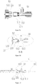
- the hemostasis apparatus 50 includes a hemostasis valve body 51 having an inner cavity 511 and a sealing member 52 arranged in the inner cavity 511.
- a pore is formed in the sealing member 52.
- the hemostasis valve body 51 may be in a T shape or Y shape.
- the hemostasis valve body 51 is a T-shaped valve.
- An external thread 510 is formed on the outer surface, which is close to the proximal end of the hemostasis valve body 51, of the hemostasis valve body 51.
- the hemostasis apparatus 50 also includes a pressing member 53 located at the proximal end of the hemostasis valve body 51 and a third connection screw cap 54 located at the distal end of the hemostasis valve body 51.
- the inner cavity 511 has a columnar section 513 and a conical section 512 which are connected with each other; the columnar section 513 is closer to the proximal end of the hemostasis valve body 51 than the conical section 512; the diameter of the columnar section 513 is equal to that of the proximal end of the conical section 512; the diameter of the proximal end of the conical section 512 is greater than that of the distal end of the conical section 512; and the sealing member 52 is adjacent to the proximal end of the conical section 512.
- the sealing member 52 is an O-shaped silica gel ring.
- the conical section 512 may be arranged at any position of the inner cavity 511 as long as the distal end of the overlay film 412 of the steel cable 41 penetrates through the distal end of the sealing member 52 after the distal end of the steel cable main body 411 penetrates through the hemostasis valve body 51 from the distal end of the hemostasis valve body 51, and the overlay film 412 of the steel cable 41 may cooperate with the sealing member 52 to isolate the distal end of the inner cavity 511 of the hemostasis valve body 51 from the outside world.
- the pressing member 53 includes a hollow pressing column 531 and a pressing screw cap 532 which surrounds the pressing column 531 and is connected with the pressing column 531; a containing space for containing the hemostasis valve body 51 is formed between the outer wall of the pressing column 531 and an internal thread of the pressing screw cap 532, and the distal end of the pressing column 531 is closer to the distal end of the hemostasis valve body 51 than the distal end of the thread of the pressing screw cap 532.
- the outer diameter of the pressing column 531 is less than the diameter of the columnar section 513 of the hemostasis valve body 51, so that the pressing column 531 may enter the inner cavity 511 of the hemostasis valve body 51; and after the hemostasis valve body 51 is in threaded connection with the pressing screw cap 532, the pressing column 531 may press against the sealing member 52.
- the sealing member 52 entering the distal end of the conical section 512 generates elastic deformation shrinkage, and then holds the overlay film 412 tight so as to isolate the distal end of the inner cavity 511 from the outside world.
- sealing member 52 also may be fixed in the hemostasis valve body 51 as long as the sealing member 52 may hold the overlay film 412 tight at the moment, for example, a circular hole of the sealing member 52 is small relative to the outer diameter of the overlay film 412, or the sealing member 52 is a sealing sheet with a crossed incision, and the like.
- a connection hose 512 communicated with the inner cavity 511 is also arranged on the side surface of the hemostasis valve body 51; the end portion, which is connected with the hemostasis valve body 51, of the connection hose 512 is closer to the distal end of the hemostasis valve body 51 than the sealing member 52; the other end of the hose 512 is connected with a three-way valve 513; a 6% Ruhr cone connection port 5131 of the three-way valve 513 is connected with an external infusion device; when the distal end of the inner cavity 511 is isolated from the outside world, the three-way valve 513 may be connected with an external radiography device; and before the interventional medical device 200 is released, an occluding effect is assessed by means of radiography.
- This embodiment is a manufacturing method of the steel cable 41 of Embodiment I.
- the method includes:
- the structure of the steel cable 41 is as shown in Figure 8 , and the steel cable 41 includes the steel cable main body 411 and an overlay film 412; polyether block amide covers the outer surface of a long-strip type inner core 4111 and the outer surface of a steel wire 4112 arranged on the inner core 4111, thus forming the overlay film 412.
- tubular body 4121 also may be made of a thermoplastic polyurethane elastomer or other thermoplastic elastomers as long as the heat shrink tubing having the melting point higher than that of the thermoplastic elastomer sleeves it.
- the structure obtained by the manufacturing method guarantees the flexibility of the distal end of the steel cable main body 411, and also improves the supporting property of the proximal end of the steel cable main body 411, thus improving the usability of a delivery system, and facilitating pushing of an interventional medical device in a human body environment.
- ways of applying the overlay film 412 to the steel cable main body 411 also may include thermal spraying, dispensing, electroplating, vacuum coating, evaporation coating, sputtering, chemical vapor deposition and the like.
- the material of the overlay film 412 also may include a macromolecular material such as a thermoset elastomer, a metal material or a polymer as long as the supporting property of the steel cable main body 411 having the overlay film 412 meets an actual requirement.
- This embodiment is a method of applying the delivery system 100 of Embodiment I to clinical delivery of an interventional medical device 200, including:
- the pressing screw cap 532 is rotated anticlockwise at first to enable the sealing member 52 to return to the loose state; second, a steel cable 41 is retracted to the proximal end of a delivery system 100 to drive the interventional medical device to be collected into a delivery sheath 11; third, the connection between a second connection screw cap 321 of a loading apparatus 30 and a sheath connector 12 is cut off; then the inappropriate interventional medical device is removed from the sheath 11, the threaded connection between the inappropriate interventional medical device and the steel cable 41 is cut off, and a new interventional medical device is replaced; fifth, steps (3) to (7) of Embodiment III are repeatedly executed until the appropriate interventional medical device is pushed to an appointed treatment position; and finally, the step (8) is executed to complete the operation.
- the delivery system may effectively assist a doctor in finishing an assessment of the operation effect during operation, and the radiography assessment may be carried out without releasing the device, so that the operation process is more convenient and faster.
- the disclosure improves the supporting properties of the steel cable, and facilitates pushing of the interventional medical device.
- the occluding effect may not be judged through radiography before the pushing steel cable is separated from the interventional medical device, but is only judged through ultrasonic observation, so that resources equipped for operation are added.
- ultrasonic observation is not as clear as radiography observation, thus reducing the treatment effect of the operation. If the size of the interventional medical device is selected inappropriately, and the spread position is not good, the interventional medical device only has to be recycled at first, and then is delivered and released, thus judging the operation effect.
- the sealing member cooperating with the overlay film of the steel cable is arranged in the hemostasis valve body so that the distal end of the inner cavity of the hemostasis valve body may be isolated from the outside world during operation, real-time radiography assessment may be carried out during the operation, controllability of releasing the device and operation effect assessment are realized, and the harm to patients, which is caused by recycling of the interventional medical after being released, due to an inappropriate model selection of the interventional medical device or requirement for adjustment of the spread position, is effectively avoided.
Landscapes
- Health & Medical Sciences (AREA)
- Life Sciences & Earth Sciences (AREA)
- Heart & Thoracic Surgery (AREA)
- Surgery (AREA)
- Veterinary Medicine (AREA)
- Public Health (AREA)
- General Health & Medical Sciences (AREA)
- Engineering & Computer Science (AREA)
- Biomedical Technology (AREA)
- Animal Behavior & Ethology (AREA)
- Molecular Biology (AREA)
- Medical Informatics (AREA)
- Nuclear Medicine, Radiotherapy & Molecular Imaging (AREA)
- Vascular Medicine (AREA)
- Reproductive Health (AREA)
- Pulmonology (AREA)
- Anesthesiology (AREA)
- Hematology (AREA)
- Surgical Instruments (AREA)
- Cardiology (AREA)
Applications Claiming Priority (2)
| Application Number | Priority Date | Filing Date | Title |
|---|---|---|---|
| CN201521133723.5U CN205729432U (zh) | 2015-12-30 | 2015-12-30 | 推送装置及输送系统 |
| PCT/CN2016/080685 WO2017113554A1 (zh) | 2015-12-30 | 2016-04-29 | 推送装置及输送系统 |
Publications (2)
| Publication Number | Publication Date |
|---|---|
| EP3398566A1 true EP3398566A1 (de) | 2018-11-07 |
| EP3398566A4 EP3398566A4 (de) | 2020-12-02 |
Family
ID=57387886
Family Applications (1)
| Application Number | Title | Priority Date | Filing Date |
|---|---|---|---|
| EP16880362.5A Pending EP3398566A4 (de) | 2015-12-30 | 2016-04-29 | Schubvorrichtung und fördersystem |
Country Status (4)
| Country | Link |
|---|---|
| US (1) | US10751061B2 (de) |
| EP (1) | EP3398566A4 (de) |
| CN (1) | CN205729432U (de) |
| WO (1) | WO2017113554A1 (de) |
Families Citing this family (17)
| Publication number | Priority date | Publication date | Assignee | Title |
|---|---|---|---|---|
| US10448971B2 (en) | 2016-12-21 | 2019-10-22 | Medtronic, Inc. | Apparatus for forming a passageway in tissue and associated interventional medical systems |
| CN108272538B (zh) * | 2016-12-30 | 2020-06-12 | 先健科技(深圳)有限公司 | 肺减容弹性植入体及肺减容器械 |
| CN108261216B (zh) * | 2016-12-30 | 2021-03-19 | 先健科技(深圳)有限公司 | 左心耳封堵器的输送系统 |
| US10925640B2 (en) | 2017-02-23 | 2021-02-23 | St. Jude Medical, Cardiology Division, Inc. | Flexible torque cable for delivery of medical devices |
| CN109199501A (zh) * | 2017-07-04 | 2019-01-15 | 先健科技(深圳)有限公司 | 输送鞘管及输送系统 |
| CN109247959B (zh) * | 2017-07-13 | 2020-07-03 | 先健科技(深圳)有限公司 | 封堵器推送装置及输送系统 |
| CN110384531A (zh) * | 2018-04-20 | 2019-10-29 | 杭州诺茂医疗科技有限公司 | 递送装置及输送系统 |
| CN110638488B (zh) * | 2018-06-26 | 2025-08-15 | 杭州唯强医疗科技有限公司 | 连接可靠的植入物推送装置及植入物输送系统 |
| CN110638490B (zh) * | 2018-06-26 | 2025-08-15 | 杭州唯强医疗科技有限公司 | 可锁定的植入物推送装置及植入物输送系统 |
| CN108852459B (zh) * | 2018-07-25 | 2024-01-30 | 深圳市远为医疗技术有限公司 | 一种可塑形多功能颅脑造通器 |
| CN111803165B (zh) * | 2019-04-11 | 2024-09-20 | 北京领健医疗科技有限公司 | 左心耳闭合器输送系统 |
| CN111803169A (zh) * | 2019-04-12 | 2020-10-23 | 杭州诺茂医疗科技有限公司 | 输送顺畅的介入医疗器械输送系统 |
| WO2022132639A1 (en) * | 2020-12-14 | 2022-06-23 | Icahn School Of Medicine At Mount Sinai | Hemostasis valve device |
| CN113827312B (zh) * | 2021-09-18 | 2023-06-13 | 晨兴(南通)医疗器械有限公司 | 肺动脉取栓器用输送系统 |
| CN116407172B (zh) * | 2021-12-31 | 2025-11-25 | 先健科技(深圳)有限公司 | 一种密封系统及输送鞘 |
| CN118252553A (zh) * | 2022-12-27 | 2024-06-28 | 先健科技(深圳)有限公司 | 输送器和输送系统 |
| CN118986422B (zh) * | 2023-05-22 | 2025-12-02 | 先健科技(深圳)有限公司 | 输送系统 |
Family Cites Families (20)
| Publication number | Priority date | Publication date | Assignee | Title |
|---|---|---|---|---|
| ATE120354T1 (de) | 1990-07-09 | 1995-04-15 | Wilson Cook Medical Inc | Vorrichtung zum herausziehen von rekanalisierungsrohren. |
| DE69430916T2 (de) * | 1993-04-28 | 2002-10-31 | Biosense Webster Inc., Baldwin Park | Elektrophysiologiekatheter mit vorgebogener spitze |
| JP3563540B2 (ja) * | 1996-09-13 | 2004-09-08 | テルモ株式会社 | カテーテル |
| JP4668368B2 (ja) * | 1997-08-22 | 2011-04-13 | シュナイダー/ナミック | 右冠動脈用カテーテル |
| JP4898993B2 (ja) * | 2000-01-28 | 2012-03-21 | クック メディカル テクノロジーズ エルエルシー | 複数本のワイヤを備えている脈管内医療装置 |
| US6571131B1 (en) * | 2000-11-10 | 2003-05-27 | Biosense Webster, Inc. | Deflectable catheter with modifiable handle |
| JP2002275774A (ja) * | 2001-03-21 | 2002-09-25 | Asahi Intecc Co Ltd | 医療用チューブ体、バルーンカテーテルおよび医療用ガイドワイヤ |
| US8083728B2 (en) * | 2004-03-18 | 2011-12-27 | C. R. Bard, Inc. | Multifunction adaptor for an open-ended catheter |
| DE102004045586B3 (de) * | 2004-09-17 | 2006-05-04 | Karl Storz Gmbh & Co. Kg | Ventil für medizinische Instrumente |
| DE102005022688B4 (de) * | 2005-05-12 | 2011-06-30 | EPflex Feinwerktechnik GmbH, 72581 | Führungsdraht für ein medizinisches Instrument |
| JP4680007B2 (ja) * | 2005-08-29 | 2011-05-11 | 日本ライフライン株式会社 | スタイレット |
| CN101416890A (zh) * | 2007-10-22 | 2009-04-29 | 北京有色金属研究总院 | 下腔静脉滤器回收装置 |
| US9474889B2 (en) * | 2008-02-19 | 2016-10-25 | Bipore Medical Devices, Inc. | Sealing arrangement for medical introducer |
| WO2010068814A1 (en) * | 2008-12-10 | 2010-06-17 | Boston Scientific Scimed, Inc. | Introducer sheath with an embolic coil device and methods for making the same |
| US8696698B2 (en) * | 2009-12-02 | 2014-04-15 | Surefire Medical, Inc. | Microvalve protection device and method of use for protection against embolization agent reflux |
| WO2013067168A1 (en) | 2011-11-02 | 2013-05-10 | Boston Scientific Scimed, Inc. | Stent delivery systems and methods for use |
| WO2013070686A1 (en) | 2011-11-08 | 2013-05-16 | Boston Scientific Scimed, Inc. | Handle assembly for a left atrial appendage occlusion device |
| CN202859386U (zh) * | 2012-09-28 | 2013-04-10 | 乐普(北京)医疗器械股份有限公司 | 经导管输送人工心脏瓣膜系统 |
| US20170197059A1 (en) * | 2014-06-03 | 2017-07-13 | Sumitomo Bakelite Co., Ltd. | Medical device |
| CN104586440B (zh) | 2014-12-31 | 2017-12-26 | 上海形状记忆合金材料有限公司 | 一种心脏缺损封堵器输送系统 |
-
2015
- 2015-12-30 CN CN201521133723.5U patent/CN205729432U/zh not_active Expired - Lifetime
-
2016
- 2016-04-29 WO PCT/CN2016/080685 patent/WO2017113554A1/zh not_active Ceased
- 2016-04-29 EP EP16880362.5A patent/EP3398566A4/de active Pending
- 2016-04-29 US US15/777,317 patent/US10751061B2/en active Active
Also Published As
| Publication number | Publication date |
|---|---|
| EP3398566A4 (de) | 2020-12-02 |
| US10751061B2 (en) | 2020-08-25 |
| US20180296221A1 (en) | 2018-10-18 |
| CN205729432U (zh) | 2016-11-30 |
| WO2017113554A1 (zh) | 2017-07-06 |
Similar Documents
| Publication | Publication Date | Title |
|---|---|---|
| US10751061B2 (en) | Pushing apparatus and delivery system | |
| CN109965946B (zh) | 扩张穿刺装置、组件及医疗器械 | |
| US20240091506A1 (en) | Transseptal puncture apparatus and method for using the same | |
| US8292910B2 (en) | Transseptal puncture apparatus | |
| US8992556B2 (en) | Transseptal puncture apparatus | |
| US9572957B2 (en) | Steerable medical devices and steering assemblies | |
| US7226466B2 (en) | Flexible delivery system | |
| US20190021861A1 (en) | Anti-Lockup Thread Attachment Mechanism and Method of Use Thereof | |
| US8235986B2 (en) | Systems and methods for transeptal cardiac procedures, including tissue penetrating members and associated methods | |
| US8620399B2 (en) | Deflectable medical devices and methods of manufacturing therefor | |
| CA2911661C (en) | Catheters and dilators for trans-septal procedures and methods for making and using them | |
| WO2019167985A1 (ja) | ガイドワイヤおよび医療デバイス | |
| CN108261216B (zh) | 左心耳封堵器的输送系统 | |
| CN116211454A (zh) | 一种穿刺装置以及穿刺系统 | |
| CN222172225U (zh) | 房间隔穿刺针及房间隔穿刺系统 | |
| CN207323512U (zh) | 左心耳封堵器的输送系统 | |
| CN114917455A (zh) | 导引导管内芯及无鞘导引导管系统 | |
| US10285682B2 (en) | Medical device and treatment method | |
| US20230397914A1 (en) | Implants, systems, and methods for vascular treatment | |
| CN104667413B (zh) | 推送器 | |
| CN118986422A (zh) | 输送系统 | |
| WO2017122432A1 (ja) | 心臓用治療デバイス及び心臓治療方法 | |
| JP2024121329A (ja) | カテーテルおよびカテーテルシステム |
Legal Events
| Date | Code | Title | Description |
|---|---|---|---|
| STAA | Information on the status of an ep patent application or granted ep patent |
Free format text: STATUS: THE INTERNATIONAL PUBLICATION HAS BEEN MADE |
|
| PUAI | Public reference made under article 153(3) epc to a published international application that has entered the european phase |
Free format text: ORIGINAL CODE: 0009012 |
|
| STAA | Information on the status of an ep patent application or granted ep patent |
Free format text: STATUS: REQUEST FOR EXAMINATION WAS MADE |
|
| 17P | Request for examination filed |
Effective date: 20180718 |
|
| AK | Designated contracting states |
Kind code of ref document: A1 Designated state(s): AL AT BE BG CH CY CZ DE DK EE ES FI FR GB GR HR HU IE IS IT LI LT LU LV MC MK MT NL NO PL PT RO RS SE SI SK SM TR |
|
| AX | Request for extension of the european patent |
Extension state: BA ME |
|
| DAV | Request for validation of the european patent (deleted) | ||
| DAX | Request for extension of the european patent (deleted) | ||
| RIC1 | Information provided on ipc code assigned before grant |
Ipc: A61B 17/12 20060101ALI20190723BHEP Ipc: A61F 2/95 20130101AFI20190723BHEP Ipc: A61M 39/06 20060101ALI20190723BHEP |
|
| A4 | Supplementary search report drawn up and despatched |
Effective date: 20201030 |
|
| RIC1 | Information provided on ipc code assigned before grant |
Ipc: A61M 39/06 20060101ALI20201026BHEP Ipc: A61F 2/95 20130101AFI20201026BHEP Ipc: A61B 17/12 20060101ALI20201026BHEP |
|
| STAA | Information on the status of an ep patent application or granted ep patent |
Free format text: STATUS: EXAMINATION IS IN PROGRESS |
|
| 17Q | First examination report despatched |
Effective date: 20240517 |