EP3398564A1 - Luminaler stent - Google Patents
Luminaler stent Download PDFInfo
- Publication number
- EP3398564A1 EP3398564A1 EP16881091.9A EP16881091A EP3398564A1 EP 3398564 A1 EP3398564 A1 EP 3398564A1 EP 16881091 A EP16881091 A EP 16881091A EP 3398564 A1 EP3398564 A1 EP 3398564A1
- Authority
- EP
- European Patent Office
- Prior art keywords
- tubular body
- radial
- stent graft
- luminal stent
- supporting structure
- Prior art date
- Legal status (The legal status is an assumption and is not a legal conclusion. Google has not performed a legal analysis and makes no representation as to the accuracy of the status listed.)
- Granted
Links
Images


Classifications
-
- A—HUMAN NECESSITIES
- A61—MEDICAL OR VETERINARY SCIENCE; HYGIENE
- A61F—FILTERS IMPLANTABLE INTO BLOOD VESSELS; PROSTHESES; DEVICES PROVIDING PATENCY TO, OR PREVENTING COLLAPSING OF, TUBULAR STRUCTURES OF THE BODY, e.g. STENTS; ORTHOPAEDIC, NURSING OR CONTRACEPTIVE DEVICES; FOMENTATION; TREATMENT OR PROTECTION OF EYES OR EARS; BANDAGES, DRESSINGS OR ABSORBENT PADS; FIRST-AID KITS
- A61F2/00—Filters implantable into blood vessels; Prostheses, i.e. artificial substitutes or replacements for parts of the body; Appliances for connecting them with the body; Devices providing patency to, or preventing collapsing of, tubular structures of the body, e.g. stents
- A61F2/02—Prostheses implantable into the body
- A61F2/04—Hollow or tubular parts of organs, e.g. bladders, tracheae, bronchi or bile ducts
- A61F2/06—Blood vessels
- A61F2/07—Stent-grafts
-
- A—HUMAN NECESSITIES
- A61—MEDICAL OR VETERINARY SCIENCE; HYGIENE
- A61F—FILTERS IMPLANTABLE INTO BLOOD VESSELS; PROSTHESES; DEVICES PROVIDING PATENCY TO, OR PREVENTING COLLAPSING OF, TUBULAR STRUCTURES OF THE BODY, e.g. STENTS; ORTHOPAEDIC, NURSING OR CONTRACEPTIVE DEVICES; FOMENTATION; TREATMENT OR PROTECTION OF EYES OR EARS; BANDAGES, DRESSINGS OR ABSORBENT PADS; FIRST-AID KITS
- A61F2/00—Filters implantable into blood vessels; Prostheses, i.e. artificial substitutes or replacements for parts of the body; Appliances for connecting them with the body; Devices providing patency to, or preventing collapsing of, tubular structures of the body, e.g. stents
- A61F2/82—Devices providing patency to, or preventing collapsing of, tubular structures of the body, e.g. stents
- A61F2/852—Two or more distinct overlapping stents
-
- A—HUMAN NECESSITIES
- A61—MEDICAL OR VETERINARY SCIENCE; HYGIENE
- A61F—FILTERS IMPLANTABLE INTO BLOOD VESSELS; PROSTHESES; DEVICES PROVIDING PATENCY TO, OR PREVENTING COLLAPSING OF, TUBULAR STRUCTURES OF THE BODY, e.g. STENTS; ORTHOPAEDIC, NURSING OR CONTRACEPTIVE DEVICES; FOMENTATION; TREATMENT OR PROTECTION OF EYES OR EARS; BANDAGES, DRESSINGS OR ABSORBENT PADS; FIRST-AID KITS
- A61F2/00—Filters implantable into blood vessels; Prostheses, i.e. artificial substitutes or replacements for parts of the body; Appliances for connecting them with the body; Devices providing patency to, or preventing collapsing of, tubular structures of the body, e.g. stents
- A61F2/82—Devices providing patency to, or preventing collapsing of, tubular structures of the body, e.g. stents
- A61F2/86—Stents in a form characterised by the wire-like elements; Stents in the form characterised by a net-like or mesh-like structure
-
- A—HUMAN NECESSITIES
- A61—MEDICAL OR VETERINARY SCIENCE; HYGIENE
- A61F—FILTERS IMPLANTABLE INTO BLOOD VESSELS; PROSTHESES; DEVICES PROVIDING PATENCY TO, OR PREVENTING COLLAPSING OF, TUBULAR STRUCTURES OF THE BODY, e.g. STENTS; ORTHOPAEDIC, NURSING OR CONTRACEPTIVE DEVICES; FOMENTATION; TREATMENT OR PROTECTION OF EYES OR EARS; BANDAGES, DRESSINGS OR ABSORBENT PADS; FIRST-AID KITS
- A61F2/00—Filters implantable into blood vessels; Prostheses, i.e. artificial substitutes or replacements for parts of the body; Appliances for connecting them with the body; Devices providing patency to, or preventing collapsing of, tubular structures of the body, e.g. stents
- A61F2/82—Devices providing patency to, or preventing collapsing of, tubular structures of the body, e.g. stents
- A61F2/848—Devices providing patency to, or preventing collapsing of, tubular structures of the body, e.g. stents having means for fixation to the vessel wall, e.g. barbs
-
- A—HUMAN NECESSITIES
- A61—MEDICAL OR VETERINARY SCIENCE; HYGIENE
- A61F—FILTERS IMPLANTABLE INTO BLOOD VESSELS; PROSTHESES; DEVICES PROVIDING PATENCY TO, OR PREVENTING COLLAPSING OF, TUBULAR STRUCTURES OF THE BODY, e.g. STENTS; ORTHOPAEDIC, NURSING OR CONTRACEPTIVE DEVICES; FOMENTATION; TREATMENT OR PROTECTION OF EYES OR EARS; BANDAGES, DRESSINGS OR ABSORBENT PADS; FIRST-AID KITS
- A61F2/00—Filters implantable into blood vessels; Prostheses, i.e. artificial substitutes or replacements for parts of the body; Appliances for connecting them with the body; Devices providing patency to, or preventing collapsing of, tubular structures of the body, e.g. stents
- A61F2/82—Devices providing patency to, or preventing collapsing of, tubular structures of the body, e.g. stents
- A61F2/94—Stents retaining their form, i.e. not being deformable, after placement in the predetermined place
-
- A—HUMAN NECESSITIES
- A61—MEDICAL OR VETERINARY SCIENCE; HYGIENE
- A61F—FILTERS IMPLANTABLE INTO BLOOD VESSELS; PROSTHESES; DEVICES PROVIDING PATENCY TO, OR PREVENTING COLLAPSING OF, TUBULAR STRUCTURES OF THE BODY, e.g. STENTS; ORTHOPAEDIC, NURSING OR CONTRACEPTIVE DEVICES; FOMENTATION; TREATMENT OR PROTECTION OF EYES OR EARS; BANDAGES, DRESSINGS OR ABSORBENT PADS; FIRST-AID KITS
- A61F2/00—Filters implantable into blood vessels; Prostheses, i.e. artificial substitutes or replacements for parts of the body; Appliances for connecting them with the body; Devices providing patency to, or preventing collapsing of, tubular structures of the body, e.g. stents
- A61F2/02—Prostheses implantable into the body
- A61F2/04—Hollow or tubular parts of organs, e.g. bladders, tracheae, bronchi or bile ducts
- A61F2/06—Blood vessels
- A61F2002/061—Blood vessels provided with means for allowing access to secondary lumens
-
- A—HUMAN NECESSITIES
- A61—MEDICAL OR VETERINARY SCIENCE; HYGIENE
- A61F—FILTERS IMPLANTABLE INTO BLOOD VESSELS; PROSTHESES; DEVICES PROVIDING PATENCY TO, OR PREVENTING COLLAPSING OF, TUBULAR STRUCTURES OF THE BODY, e.g. STENTS; ORTHOPAEDIC, NURSING OR CONTRACEPTIVE DEVICES; FOMENTATION; TREATMENT OR PROTECTION OF EYES OR EARS; BANDAGES, DRESSINGS OR ABSORBENT PADS; FIRST-AID KITS
- A61F2/00—Filters implantable into blood vessels; Prostheses, i.e. artificial substitutes or replacements for parts of the body; Appliances for connecting them with the body; Devices providing patency to, or preventing collapsing of, tubular structures of the body, e.g. stents
- A61F2/02—Prostheses implantable into the body
- A61F2/04—Hollow or tubular parts of organs, e.g. bladders, tracheae, bronchi or bile ducts
- A61F2/06—Blood vessels
- A61F2/07—Stent-grafts
- A61F2002/077—Stent-grafts having means to fill the space between stent-graft and aneurysm wall, e.g. a sleeve
-
- A—HUMAN NECESSITIES
- A61—MEDICAL OR VETERINARY SCIENCE; HYGIENE
- A61F—FILTERS IMPLANTABLE INTO BLOOD VESSELS; PROSTHESES; DEVICES PROVIDING PATENCY TO, OR PREVENTING COLLAPSING OF, TUBULAR STRUCTURES OF THE BODY, e.g. STENTS; ORTHOPAEDIC, NURSING OR CONTRACEPTIVE DEVICES; FOMENTATION; TREATMENT OR PROTECTION OF EYES OR EARS; BANDAGES, DRESSINGS OR ABSORBENT PADS; FIRST-AID KITS
- A61F2/00—Filters implantable into blood vessels; Prostheses, i.e. artificial substitutes or replacements for parts of the body; Appliances for connecting them with the body; Devices providing patency to, or preventing collapsing of, tubular structures of the body, e.g. stents
- A61F2/82—Devices providing patency to, or preventing collapsing of, tubular structures of the body, e.g. stents
- A61F2/848—Devices providing patency to, or preventing collapsing of, tubular structures of the body, e.g. stents having means for fixation to the vessel wall, e.g. barbs
- A61F2002/8486—Devices providing patency to, or preventing collapsing of, tubular structures of the body, e.g. stents having means for fixation to the vessel wall, e.g. barbs provided on at least one of the ends
-
- A—HUMAN NECESSITIES
- A61—MEDICAL OR VETERINARY SCIENCE; HYGIENE
- A61F—FILTERS IMPLANTABLE INTO BLOOD VESSELS; PROSTHESES; DEVICES PROVIDING PATENCY TO, OR PREVENTING COLLAPSING OF, TUBULAR STRUCTURES OF THE BODY, e.g. STENTS; ORTHOPAEDIC, NURSING OR CONTRACEPTIVE DEVICES; FOMENTATION; TREATMENT OR PROTECTION OF EYES OR EARS; BANDAGES, DRESSINGS OR ABSORBENT PADS; FIRST-AID KITS
- A61F2210/00—Particular material properties of prostheses classified in groups A61F2/00 - A61F2/26 or A61F2/82 or A61F9/00 or A61F11/00 or subgroups thereof
- A61F2210/0076—Particular material properties of prostheses classified in groups A61F2/00 - A61F2/26 or A61F2/82 or A61F9/00 or A61F11/00 or subgroups thereof multilayered, e.g. laminated structures
-
- A—HUMAN NECESSITIES
- A61—MEDICAL OR VETERINARY SCIENCE; HYGIENE
- A61F—FILTERS IMPLANTABLE INTO BLOOD VESSELS; PROSTHESES; DEVICES PROVIDING PATENCY TO, OR PREVENTING COLLAPSING OF, TUBULAR STRUCTURES OF THE BODY, e.g. STENTS; ORTHOPAEDIC, NURSING OR CONTRACEPTIVE DEVICES; FOMENTATION; TREATMENT OR PROTECTION OF EYES OR EARS; BANDAGES, DRESSINGS OR ABSORBENT PADS; FIRST-AID KITS
- A61F2220/00—Fixations or connections for prostheses classified in groups A61F2/00 - A61F2/26 or A61F2/82 or A61F9/00 or A61F11/00 or subgroups thereof
- A61F2220/0025—Connections or couplings between prosthetic parts, e.g. between modular parts; Connecting elements
- A61F2220/005—Connections or couplings between prosthetic parts, e.g. between modular parts; Connecting elements using adhesives
-
- A—HUMAN NECESSITIES
- A61—MEDICAL OR VETERINARY SCIENCE; HYGIENE
- A61F—FILTERS IMPLANTABLE INTO BLOOD VESSELS; PROSTHESES; DEVICES PROVIDING PATENCY TO, OR PREVENTING COLLAPSING OF, TUBULAR STRUCTURES OF THE BODY, e.g. STENTS; ORTHOPAEDIC, NURSING OR CONTRACEPTIVE DEVICES; FOMENTATION; TREATMENT OR PROTECTION OF EYES OR EARS; BANDAGES, DRESSINGS OR ABSORBENT PADS; FIRST-AID KITS
- A61F2220/00—Fixations or connections for prostheses classified in groups A61F2/00 - A61F2/26 or A61F2/82 or A61F9/00 or A61F11/00 or subgroups thereof
- A61F2220/0025—Connections or couplings between prosthetic parts, e.g. between modular parts; Connecting elements
- A61F2220/0058—Connections or couplings between prosthetic parts, e.g. between modular parts; Connecting elements soldered or brazed or welded
-
- A—HUMAN NECESSITIES
- A61—MEDICAL OR VETERINARY SCIENCE; HYGIENE
- A61F—FILTERS IMPLANTABLE INTO BLOOD VESSELS; PROSTHESES; DEVICES PROVIDING PATENCY TO, OR PREVENTING COLLAPSING OF, TUBULAR STRUCTURES OF THE BODY, e.g. STENTS; ORTHOPAEDIC, NURSING OR CONTRACEPTIVE DEVICES; FOMENTATION; TREATMENT OR PROTECTION OF EYES OR EARS; BANDAGES, DRESSINGS OR ABSORBENT PADS; FIRST-AID KITS
- A61F2220/00—Fixations or connections for prostheses classified in groups A61F2/00 - A61F2/26 or A61F2/82 or A61F9/00 or A61F11/00 or subgroups thereof
- A61F2220/0025—Connections or couplings between prosthetic parts, e.g. between modular parts; Connecting elements
- A61F2220/0075—Connections or couplings between prosthetic parts, e.g. between modular parts; Connecting elements sutured, ligatured or stitched, retained or tied with a rope, string, thread, wire or cable
-
- A—HUMAN NECESSITIES
- A61—MEDICAL OR VETERINARY SCIENCE; HYGIENE
- A61F—FILTERS IMPLANTABLE INTO BLOOD VESSELS; PROSTHESES; DEVICES PROVIDING PATENCY TO, OR PREVENTING COLLAPSING OF, TUBULAR STRUCTURES OF THE BODY, e.g. STENTS; ORTHOPAEDIC, NURSING OR CONTRACEPTIVE DEVICES; FOMENTATION; TREATMENT OR PROTECTION OF EYES OR EARS; BANDAGES, DRESSINGS OR ABSORBENT PADS; FIRST-AID KITS
- A61F2230/00—Geometry of prostheses classified in groups A61F2/00 - A61F2/26 or A61F2/82 or A61F9/00 or A61F11/00 or subgroups thereof
- A61F2230/0063—Three-dimensional shapes
- A61F2230/0067—Three-dimensional shapes conical
-
- A—HUMAN NECESSITIES
- A61—MEDICAL OR VETERINARY SCIENCE; HYGIENE
- A61F—FILTERS IMPLANTABLE INTO BLOOD VESSELS; PROSTHESES; DEVICES PROVIDING PATENCY TO, OR PREVENTING COLLAPSING OF, TUBULAR STRUCTURES OF THE BODY, e.g. STENTS; ORTHOPAEDIC, NURSING OR CONTRACEPTIVE DEVICES; FOMENTATION; TREATMENT OR PROTECTION OF EYES OR EARS; BANDAGES, DRESSINGS OR ABSORBENT PADS; FIRST-AID KITS
- A61F2250/00—Special features of prostheses classified in groups A61F2/00 - A61F2/26 or A61F2/82 or A61F9/00 or A61F11/00 or subgroups thereof
- A61F2250/0003—Special features of prostheses classified in groups A61F2/00 - A61F2/26 or A61F2/82 or A61F9/00 or A61F11/00 or subgroups thereof having an inflatable pocket filled with fluid, e.g. liquid or gas
-
- A—HUMAN NECESSITIES
- A61—MEDICAL OR VETERINARY SCIENCE; HYGIENE
- A61F—FILTERS IMPLANTABLE INTO BLOOD VESSELS; PROSTHESES; DEVICES PROVIDING PATENCY TO, OR PREVENTING COLLAPSING OF, TUBULAR STRUCTURES OF THE BODY, e.g. STENTS; ORTHOPAEDIC, NURSING OR CONTRACEPTIVE DEVICES; FOMENTATION; TREATMENT OR PROTECTION OF EYES OR EARS; BANDAGES, DRESSINGS OR ABSORBENT PADS; FIRST-AID KITS
- A61F2250/00—Special features of prostheses classified in groups A61F2/00 - A61F2/26 or A61F2/82 or A61F9/00 or A61F11/00 or subgroups thereof
- A61F2250/0014—Special features of prostheses classified in groups A61F2/00 - A61F2/26 or A61F2/82 or A61F9/00 or A61F11/00 or subgroups thereof having different values of a given property or geometrical feature, e.g. mechanical property or material property, at different locations within the same prosthesis
- A61F2250/0018—Special features of prostheses classified in groups A61F2/00 - A61F2/26 or A61F2/82 or A61F9/00 or A61F11/00 or subgroups thereof having different values of a given property or geometrical feature, e.g. mechanical property or material property, at different locations within the same prosthesis differing in elasticity, stiffness or compressibility
-
- A—HUMAN NECESSITIES
- A61—MEDICAL OR VETERINARY SCIENCE; HYGIENE
- A61F—FILTERS IMPLANTABLE INTO BLOOD VESSELS; PROSTHESES; DEVICES PROVIDING PATENCY TO, OR PREVENTING COLLAPSING OF, TUBULAR STRUCTURES OF THE BODY, e.g. STENTS; ORTHOPAEDIC, NURSING OR CONTRACEPTIVE DEVICES; FOMENTATION; TREATMENT OR PROTECTION OF EYES OR EARS; BANDAGES, DRESSINGS OR ABSORBENT PADS; FIRST-AID KITS
- A61F2250/00—Special features of prostheses classified in groups A61F2/00 - A61F2/26 or A61F2/82 or A61F9/00 or A61F11/00 or subgroups thereof
- A61F2250/0014—Special features of prostheses classified in groups A61F2/00 - A61F2/26 or A61F2/82 or A61F9/00 or A61F11/00 or subgroups thereof having different values of a given property or geometrical feature, e.g. mechanical property or material property, at different locations within the same prosthesis
- A61F2250/0039—Special features of prostheses classified in groups A61F2/00 - A61F2/26 or A61F2/82 or A61F9/00 or A61F11/00 or subgroups thereof having different values of a given property or geometrical feature, e.g. mechanical property or material property, at different locations within the same prosthesis differing in diameter
-
- A—HUMAN NECESSITIES
- A61—MEDICAL OR VETERINARY SCIENCE; HYGIENE
- A61F—FILTERS IMPLANTABLE INTO BLOOD VESSELS; PROSTHESES; DEVICES PROVIDING PATENCY TO, OR PREVENTING COLLAPSING OF, TUBULAR STRUCTURES OF THE BODY, e.g. STENTS; ORTHOPAEDIC, NURSING OR CONTRACEPTIVE DEVICES; FOMENTATION; TREATMENT OR PROTECTION OF EYES OR EARS; BANDAGES, DRESSINGS OR ABSORBENT PADS; FIRST-AID KITS
- A61F2250/00—Special features of prostheses classified in groups A61F2/00 - A61F2/26 or A61F2/82 or A61F9/00 or A61F11/00 or subgroups thereof
- A61F2250/0058—Additional features; Implant or prostheses properties not otherwise provided for
- A61F2250/006—Additional features; Implant or prostheses properties not otherwise provided for modular
- A61F2250/0063—Nested prosthetic parts
-
- A—HUMAN NECESSITIES
- A61—MEDICAL OR VETERINARY SCIENCE; HYGIENE
- A61F—FILTERS IMPLANTABLE INTO BLOOD VESSELS; PROSTHESES; DEVICES PROVIDING PATENCY TO, OR PREVENTING COLLAPSING OF, TUBULAR STRUCTURES OF THE BODY, e.g. STENTS; ORTHOPAEDIC, NURSING OR CONTRACEPTIVE DEVICES; FOMENTATION; TREATMENT OR PROTECTION OF EYES OR EARS; BANDAGES, DRESSINGS OR ABSORBENT PADS; FIRST-AID KITS
- A61F2250/00—Special features of prostheses classified in groups A61F2/00 - A61F2/26 or A61F2/82 or A61F9/00 or A61F11/00 or subgroups thereof
- A61F2250/0058—Additional features; Implant or prostheses properties not otherwise provided for
- A61F2250/0069—Sealing means
Definitions
- the present application relates to an implanted medical device, and more particularly relates to a luminal stent graft and a luminal stent graft system.
- a luminal stent graft may be adopted to implement endovascular graft exclusion to isolate a diseased region in a human body lumen, for example, the luminal stent graft may be adopted to isolate an artery dissection or an arterial aneurysm in a blood vessel.
- This kind of method has gradually substituted traditional invasive operation due to its advantages of a small operation wound, small intraoperative blood transfusion volume, quick postoperative recovery, short hospital stay, and the like.
- the luminal stent generally has radial expandability, and is clung to a vascular cavity wall by using its radial supporting force so as to be fixed in a lumen.
- the stent graft needs to have a high enough radial supporting force, but the higher radial supporting force indicates higher rigidity of the radially unfolded stent.
- the inner walls of lumens are of different shapes, and also may have calcified plaques that would change their shapes; and the luminal stent graft with relatively high rigidity may possibly cause poorly clinging to a luminal wall, so that a space between the stent graft and a diseased luminal wall may not be completely closed.
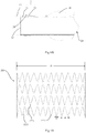
- a plaque 13 on the inner wall of a lumen 12 may form a clearance 14 between a stent graft 11 and the inner wall of the lumen 12, and blood flow may flow to a tumor cavity or a dissection false cavity through the clearance 14, thus generating type-I endoleak.
- multiple stent grafts are used cooperatively by adopting a chimney technology, a periscope technology or a sandwich technology, and then are respectively implanted into the main body blood vessels and the branch blood vessels.
- one end of a main body stent graft 15 and one end of a branch stent graft 16 are abreast implanted into the lumen 12, and the other end of the main body stent graft 15 is communicated with a relatively large main body blood vessel (not shown in the figure), but the other end of the branch stent graft 16 is communicated with a relatively small branch blood vessel (not shown in the figure).
- the radial supporting force of the branch stent graft 16 needs to be greater than that of the main body stent graft 15, and this would lead to a situation that portions, which are located at the abreast implanted positions, of the main body stent graft 15 are easier to deform radially to form a clearance 17 among the branch stent graft 16, the main body stent graft 15 and the inner wall of the lumen 12, thus generating the type-I endoleak, and the blood flow may flow to the tumor cavity or the dissection false cavity through the clearance 17.
- This type-I endoleak may appear in a thoracic aorta, an abdominal aorta or other lumens. Continuous inflow of the blood flow may cause continuous enlargement of the dissection false cavity or an arterial aneurysm cavity, and finally result in a serious consequence of breakage of the dissection false cavity or the arterial aneurysm cavity, so that the endovascular graft exclusion may fail. Therefore, to enhance the surgical effect and increase the healing success rate, it is very important for the luminal stent graft used in the endovascular graft exclusion to avoid the type-I endoleak between the stent graft and the lumen as much as possible.
- the present application provides a luminal stent graft capable of avoiding formation of an endoleak.
- a luminal stent graft including a first tubular body and a second tubular body; the second tubular body is sleeved outside the first tubular body, and at least one end of the second tubular body is sealingly connected with the outer surface of the first tubular body; the luminal stent graft has a radial supporting section; in the radial supporting section, the first tubular body includes at least one first radial supporting structure distributed along a circumferential direction of the first tubular body; the second tubular body includes at least one second radial supporting structure distributed along a circumferential direction of the second tubular body, and a graft covering the second radial supporting structure; and the radial deformability of the second radial supporting structure is greater than that of the first radial supporting structure.
- a radial length variation of the second radial supporting structure is greater than that of the first radial supporting structure; or under the action of the same radial force, a radial length change rate of the second radial supporting structure is greater than that of the first radial supporting structure; or in case of the same radial change rate or the same radial variation, a radial external force exerted on the first radial supporting structure is greater than that exerted on the second radial supporting structure.
- the radial length variation or radial length change rate of the first radial supporting structure is 1.05 times to 10 times or two to 5 times the radial length variation or radial length change rate of the second radial supporting structure.
- the radial external force exerted on the first radial supporting structure is 1.05 times to 10 times or two to 5 times the radial external force exerted on the second radial supporting structure.
- the radial length of the second tubular body is 1.3 times to 3 times the radial length of the first tubular body.
- the radial length of the second tubular body is more than that of the first tubular body by 2 mm to 30 mm.
- the other end of the second tubular body is open, or the other end of the second tubular body is sealingly connected with the outer surface of the first tubular body.
- a maximum radial length portion of the second tubular body is located in the radial supporting section, and is provided with the second supporting structure.
- a maximum radial length portion of the second tubular body is located near to an opening of the open end of the second tubular body, or is located at the middle portion of the second tubular body.
- the second radial supporting structure is a waveform ring-like object; and in a naturally unfolded state, a maximum width m of any waveform of the waveform ring-like object along a circumferential direction and a perimeter D of the second tubular body at the waveform meets a condition that m is less than or equal to D/8 or m is less than or equal to D/10 or m1 is less than or equal to D/12 or m1 is less than or equal to D/13 or m1 is less than or equal to D/14.
- the maximum width m of any waveform of the waveform ring-like object along the circumferential direction is 1.5 mm to 5 mm, or 1.5 mm to 7 mm, or 1.5 mm to 8 mm.
- the waveform ring-like object is formed by winding a metal wire; the diameter of the metal wire is 0.05 mm to 0.32 mm, or 0.1 mm to 0.35 mm, or 0.2 mm to 0.4 mm; or, the waveform ring-like object is formed by cutting a metal tube; and a wire diameter of a metal rod forming the waveform ring-like object is 0.05 mm to 0.32 mm, or 0.1 mm to 0.35 mm, or 0.2 mm to 0.4 mm.
- a waveform height of the waveform is 2 mm to 6 mm, or 3 mm to 7 mm, or 4 mm to 8 mm.
- an axial distance between any wave crest of at least one turn of waveform ring-like object and the closest wave crest in another adjacent turn of waveform ring-like object is less than the waveform height of the turn of waveform ring-like object.
- the second radial supporting structure is a meshed structure including multiple grids; and in the naturally unfolded state, the maximum width m1 of any grid along the circumferential direction and the perimeter D of the second tubular body at the grid meets a condition that m1 is less than or equal to D/12 or m1 is less than or equal to D/13 or m1 is less than or equal to D/14.
- the maximum width m1 of any grid along the circumferential direction is 1.5 mm to 5 mm, or 1.5 mm to 7 mm, or 1.5 mm to 8 mm.
- the maximum length of any grid along an axial direction is 4 mm to 12 mm, or 6 mm to 14 mm, or 8 mm to 16 mm.
- the first tubular body in the radial supporting section, also includes an overlay film covering the first radial supporting structure.
- At least one end of the first tubular body has multiple convex pieces extending in parallel to the longitudinal axis of the first tubular body, and a gap is reserved between two adjacent convex pieces.
- the first tubular body includes four wave loops arrayed in sequence along a longitudinal central axis direction of the first tubular body, and the four wave loops are connected through square connecting rings.
- the first tubular body includes barrel-shaped inner overlay films, wave loops and annular outer graft; the wave loops are arranged between the barrel-shaped inner graft and the annular outer graft in a clamping manner; and at least part of wave crests and/or wave troughs of the wave loops are exposed outside.
- a graft is arranged on the first tubular body; and a hole penetrating through the graft is formed in a portion, which is near to the end portion of the first tubular body, of the graft or the wave loop, which is close to the end portion of the first tubular body, of the first tubular body is not completely covered by the graft.
- a semi-closed clearance may be formed between the first tubular body and the second tubular body, or a semi-closed clearance is formed between the second tubular body and a lumen wall; and blood flowing into the clearance may be used as a filler material to occlude a type-I endoleak channel, thus avoiding the blood from flowing into a tumor body or a dissection.
- the first tubular body and the second tubular body both have a radial supporting force, and the second tubular body has a higher radial deformability than the first tubular body, so that after being implanted into a lumen, the luminal stent may still be attached to the lumen wall through its radial supporting force under radial compression of the lumen wall; in addition, under impact of the blood flow, both the first tubular body and the second tubular body may keep radial support shapes to avoid occurrence of deformations such as wrinkling, introversion and collapse; and particularly it may ensure that the proximal end face of the luminal stent does not deform, thereby avoiding blockage of the blood flowing into the lumen.
- a luminal stent graft 2 includes a first tubular body 21 and a second tubular body 22; the second tubular body 22 is sleeved outside the first tubular body 21, and covers at least one portion of the first tubular body 21; and one end of the second tubular body 22 is sealingly connected with the peripheral surface of the first tubular body 21.
- the first tubular body 21 has radial expandability, and may be compressed under the action of an external force, and restores an initial shape through self-expansion or mechanical expansion (such as balloon dilatation expansion) and keeps the initial shape after the external force is withdrawn, so that after being implanted into a lumen, the first tubular body 21 may cling to the lumen wall through its radial supporting force to be fixed in the lumen.
- the first tubular body 21 includes a first radial supporting structure 211 arranged on the whole tubular body, for example, the first radial supporting structure 211 may be made of a memory alloy material (for example a nickel-titanium alloy), thereby having self-expansion capacity.
- the first radial supporting structure 211 may include multiple turns of waveform ring-like objects distributed along an axial direction, or may be of a meshed structure formed by weaving a metal wire, or may be of a cut meshed structure formed by cutting a metal tube.
- a person of ordinary skill in the art can select a proper first radial supporting structure 211 according to a requirement, so that no more details will be described here.
- At least a region, which is not covered by the second tubular body 22, of the first tubular body 21 also includes a first graft 212; and the first graft 212 may be a PET (polyethylene terephthalate) film or a PTFE (polytetrafluoroethylene) film, and may cover the first radial supporting structure 211 in a suturing or hot melting way.
- first graft 212 may be a PET (polyethylene terephthalate) film or a PTFE (polytetrafluoroethylene) film, and may cover the first radial supporting structure 211 in a suturing or hot melting way.
- the second tubular body 22 has radial expandability. Namely it may be compressed under the action of an external force, restores to an initial shape through self-expansion or mechanical expansion (such as balloon dilatation expansion), and keeps the initial shape after the external force is withdrawn, so that after being implanted into the lumen, the second tubular body 22 may cling to the luminal wall through its radial supporting force.
- the second tubular body 22 includes a second radial supporting structure 221 arranged on at least one portion of the tubular body, for example, the second radial supporting structure 221 may be made of a memory alloy material (for example a nickel-titanium alloy), thereby having a self-expansion capacity.
- the second radial supporting structure 221 may include multiple turns of waveform ring-like objects distributed along an axial direction, or may be a mesh structure formed by weaving a metal wire, or may be of a cut mesh structure formed by cutting a metal tube.
- the person of ordinary skill in the art can select a proper second radial supporting structure 221 according to a requirement, so that no more details will be described here.
- the whole second tubular body 22 also includes a second graft 222; and the graft may be a PET film or a PTFE film, and may cover the second radial supporting structure 221 by suturing or hot melting.
- One end of the second tubular body 22 and the first tubular body 21 may be sealingly connected via hot melting of the second graft 222 and the first graft 212, and also may be sealingly connected by suturing the second graft 222 onto the first graft 212.
- the person of ordinary skill in the art can select a proper sealing way according to a requirement, so that no more details will be described here.
- the luminal stent graft 2 has at least one radial supporting section; in the radial supporting section, the first tubular body 21 includes at least one first radial supporting structure 211 distributed along its circumferential direction; the second tubular body 22 includes at least one second radial supporting structure 221 distributed along its circumferential direction, and a second graft 222 covering the second radial supporting structure 221.
- the maximum radial length portion of the second tubular body 22 may be located in the radial supporting section, and the second radial supporting structure 221 is arranged at the maximum radial length portion.
- the maximum radial length portion of the second tubular body 22 may be located at the end portion of the open end of the second tubular body 22, or may be located at the middle portion of the second tubular body 22.
- the luminal stent graft 2 includes a radial supporting section L; and the radial supporting section L is located near to the open end, which is away from a sealingly connected portion, in the second tubular body 22.
- the second tubular body 22 covers the first tubular body 21, and has the second radial supporting structure 221.
- the luminal stent graft 2 includes a radial supporting section L1, and the radial supporting section L1 is the whole second tubular body 22.
- the second tubular body 22 covers the first tubular body 21, and has the second radial supporting structure 221.
- the radial deformability of the second radial supporting structure 221 is greater than that of the first radial supporting structure 211, that is to say, under the action of the same radial force (the sizes and the directions of radial acting forces and the acting time are all the same), the radial length variation of the first radial supporting structure 211 in the radial supporting section is less than that of the second radial supporting structure 221 at the same position; or under the action of the same radial force (the sizes and the directions of the radial acting forces and the acting time are all the same), the radial length change rate of the first radial supporting structure 211 in the radial supporting section is less than that of the second radial supporting structure 221 at the same position; and this change rate is a ratio of the radial length variation to an original radial length.
- a larger radial length variation or a larger radial length change rate indicates higher radial deformability and lower radial supportability of a radial supporting structure, and vice versa.
- a radial external force exerted on the first radial supporting structure 211 is greater than the radial external force exerted on the second radial supporting structure 221.
- a higher radial force needed indicates lower radial deformability and higher radial supportability, and vice versa.
- a flat plate pressing method may be adopted. Namely the tubular bodies 21 and 22 may be clamped in the radial supporting section along a tangential direction of the circumference of the radial supporting section by adopting two mutually parallel flat plates 18. In a test process, the two flat plates are always kept in parallel. Equal radial forces F are applied to the flat plates 18 to test the radial length variations ⁇ R or the radial length change rates ⁇ R/R of the first radial supporting structure 211 and the second radial supporting structure 221, and the directions of the radial forces F are parallel to certain diameters, which are located at pressed portions, of the tube bodies 21 and 22.
- a measured radial force F1 to be applied is used for evaluating the radial supporting force or the radial supportability, and this evaluation result is equivalent to an evaluation result obtained on the basis of the radial length variation or the radial length change rate, wherein in a situation of the same radial acting condition (the acting time and the acting way of the radial force are the same), a smaller value of the radial force F1 applied to compressing the tubular body from the original size R to R/2 indicates higher radial deformability and lower radial supportability of the tubular body, and vice versa.
- the above-mentioned flat plate pressing method is only one example test method, but not a limitation to the present application.
- the person of ordinary skill in the art can adopt any proper method to carry out a test equivalent to the flat plate pressing method, for example, a radial acting force also may be uniformly applied to the circumferential direction of the lumen for testing.
- a radial supporting force tester RX550-100 of the Machine Solution Inc (MSI) Company can be adopted.
- the radial length variation of the second radial supporting structure 221 in the radial supporting section is 1.05 times to 10 times the radial length variation of the first radial supporting structure 211 in the radial supporting section, and further may be two to 5 times.
- the radial length change rate of the second radial supporting structure 221 in the radial supporting section is 1.05 times to 10 times the radial length change rate of the first radial supporting structure 211 in the radial supporting section, and further may be two to 5 times.
- the radial force to be applied to compressing the first radial supporting structure 211 from the original size R to R/2 is 1.05 times to 10 times the radial force to be applied to compressing the second radial supporting structure 221 from the original size R to R/2, and further may be two to 5 times.
- the second radial supporting structure 221 When compared with the first radial supporting structure 211, the second radial supporting structure 221 is that if its radial deformability is extremely high, its radial supportability is low, which leads to a situation that the second radial supporting structure may not be completely radially unfolded in a releasing process, thereby causing a wrinkling or collapsing phenomenon, so that the radial deformability of the second radial supporting structure 221 will not generally exceed 10 times of the radial deformability of the first radial supporting structure 211.
- the radial deformability of the second radial supporting structure 221 is generally greater than 1.05 times of the radial deformability of the first radial supporting structure 211.
- the radial deformability of the second radial supporting structure 221 is two to 5 times, such as 3 times and 4 times, the radial deformability of the first radial supporting structure 211.
- the radial deformability described herein is a radial reacting force generated by a tubular body on an external radial acting force when the tubular body is pressed by the external radial acting force, for example, when the first tubular body 21 or the second tubular body 22 is pressed radially by a lumen after being implanted.
- higher radial reacting force generated by the tubular body indicates that this tubular body has relatively low radial deformability and relatively high radial supporting force or relatively high radial supportability, and vice versa.
- the radial reacting force generated by the first radial supporting structure 211 is relatively high, and the radial reacting force generated by the second radial supporting structure 221 is relatively low, so that the first radial supporting structure 211 has higher radial supporting force or higher radial supportability and lower radial deformability than the second tubular body 22.
- a tubular body does not have the above-mentioned radial expandability by itself, for example the one which only has a graft and does not have a radial supporting structure, it will be compressed under the external radial acting force, but after the external force is withdrawn, it may not restore to its initial shape and keep the initial shape, so that the radial reacting force generated by this tubular body on the external radial acting force may be basically ignored, and it is unnecessary to compare the radial supporting force or the radial supportability of the tubular body of this structure.
- the second radial supporting structure 221 is arranged along the circumferential direction, and further, the second radial supporting structure 221 is continuously arranged along the circumferential direction. After implantation, when a certain portion of the second radial supporting structure 221 deforms under the radial acting force, the second radial supporting structure 221 may transmit this deformation or pressure along the circumferential direction, thereby realizing that the second tubular body complies with the shape of the lumen wall and clings to the lumen wall, and the second radial supporting structure 221 may actively fill the small gaps around to avoid formation of a blood flow leak channel between the second tubular body and the lumen wall.
- the luminal stent graft 2 includes the first tubular body 21 and the second tubular body 22 covering the first tubular body 21; the first tubular body 21 may cling to the lumen wall due to its relatively low radial deformability, so that the whole luminal stent graft may be fixed in the lumen to avoid displacement or falling off from the lumen; the second tubular body 22 has the radial supporting force due to the second radial supporting structure 221, and may be radially expanded to be attached to the lumen wall, so that no clearance will be formed between the lumen wall and the second tubular body 22 due to the insufficient radial supporting force.
- the second tubular body 22 complies with the shape deformation of the inner wall of the lumen more easily, thereby avoiding formation of the clearance between the second tubular body 22 and the inner wall of the lumen and cutting off a channel or an opening that may form the type-I endoleak.
- the first tubular body 21 namely the first radial supporting structure
- the second tubular body 22 namely the second radial supporting structure
- the first tubular body 21 will keep the radial shape basically unchanged under the radial pressure of the vascular wall to avoid displacement or falling off of the luminal stent graft 2; and the second tubular body 22 will comply with the deformation under the radial pressure of the blood vessel and keep radial expansion and unfolding to avoid deformation such as collapse, sinking, and turnover.
- the luminal stent graft 2 has a proximal end 23 and a distal end 24, and it is defined here that blood flow flows from the proximal end 23 to the distal end 24 after implantation.
- the second tubular body 22 is located near to the proximal end 23 of the first tubular body 21; a tube orifice, which is close to the distal end 24, of the second tubular body 22 is sealingly connected with the peripheral surface of the first tubular body 21 to form a closed tube orifice; and the tube orifice, which is close to the proximal end 23, of the second tubular body 22 is open.
- the first tubular body 21 keeps the radial shape basically unchanged to avoid displacement or falling off, and maintains a blood flow channel unblocked;
- the second tubular body 22 may comply with the deformation at the plaque 13, and is still attached to the inner wall of the lumen and the surface of the plaque by its radial expandability, so that the clearance formed between the first tubular body 21 and the inner wall of the lumen is filled, and at the same time, no clearance will be formed among the second tubular body 22, the inner wall of the lumen and the surface of the plaque, thus cutting off the channel or the opening that may form the type-I endoleak and avoiding the blood from flowing into a tumor body or a dissection 18.
- the end, which is close to the proximal end 23, of the second tubular body 22 is open; after implantation, the second tubular body 22 complies with the deformation of the inner wall of the lumen 12, and a clearance 20 is formed between the second tubular body 22 and the first tubular body 21; when flowing from the proximal end 23 into the luminal stent graft 2, the blood also flows into the clearance 20 at the same time; as the tube orifice, which is close to the distal end 24, of the second tubular body 22 is closed, the blood flowing into the clearance 20 may achieve a sealing and filling effect, and this part of blood will be directly thrombosed in the clearance 20 to make the sealing and filling effect better.
- sealing In the sealing process, no other sealing or filling materials need to be added into the luminal stent graft 2 in advance or after the luminal stent 2 is implanted, and sealing may be realized only through inflowing blood from normal blood circulation, so that no extra biological risk caused by the sealing or filling materials will be added.
- the first tubular body 21 in the radial supporting section may only include the first radial supporting structure 211, but may not include the first graft 212. It can be understood that when compared with the structure as shown in Figure 3 , this structure is that the first tubular body 21 may still enable the whole luminal stent graft 2 to be fixed in the lumen by its relatively high radial supporting force, and the second tubular body 22 may still comply with the shape deformation of the inner wall of the lumen by its relatively low radial supporting force, and be attached into the lumen to avoid the formation of the clearance between the second tubular body 22 and the inner wall of the lumen as much as possible.
- the blood flowing into a space between the first tubular body 21 and the second tubular body 22 will flow into a channel formed by the first tubular body 21 through a gap of the first radial supporting structure 211, and then enter the blood circulation again.
- the radial length of the second tubular body 22 is 1.3 times to 3 times the radial length of the first tubular body 21, so that at this position, a clearance space is formed between the first tubular body 21 and the second tubular body 22.
- the radial length of the first tubular body 21 and the radial length of the second tubular body 22 may be respectively the radial lengths of their own radial supporting structures after the radial supporting structures are naturally radially unfolded, for example, the radial length of the second tubular body 22 here is the radial length of the second radial supporting structure 221 here.
- the radial length of the second tubular body 22 is more than that of the first tubular body 21 by 2 mm to 30 mm, so that at this position, a clearance space is formed between the first tubular body 21 and the second tubular body 22.
- a corresponding luminal stent graft is generally applied to aorta positions including an ascending aorta, an aorta arch, a thoracic descending aorta and an abdominal aorta; at the moment, the radial length of the second tubular body 22 at the same position is more than that of the first tubular body by 2 mm to 20 mm; when the radial length of the first tubular body 21 is 4 mm to 20 mm, a corresponding luminal stent graft is generally applied to a branch blood vessel such as an arch branch, a renal artery and an iliac artery; and at the same time, the radial length of the second tubular body at the same position is more than the maximum radial length of the first tubular body 21 by 3 mm to 30 mm.
- the radial length of the first tubular body 21 and the radial length of the second tubular body 22 may be respectively the radial lengths of their own radial supporting structures after the radial supporting structures are naturally radially unfolded.
- a radial length difference between the first tubular body and the second tubular body or a radial length ratio of the first tubular body to the second tubular body may be valued within a relatively large range.
- the radial length difference between the first tubular body and the second tubular body or the radial length ratio of the first tubular body to the second tubular body needs to be relatively small, for example, if the radial length difference is up to 2 mm, 3 mm or 4 mm, the first tubular body and the second tubular body may not be attached together due to their radial expandability, so that the clearance space still exists and may be kept unblocked.
- the luminal stent graft according to the embodiment of the present application has a wide range of applications and a high stability in blocking the leak.
- the stent graft is generally applied to aorta positions, including an ascending aorta, an aorta arch, a thoracic descending aorta and an abdominal aorta, and all branch blood vessels.
- the radial length variation of the second radial supporting structure 221 is slightly greater than that of the first radial supporting structure 211 in the radial supporting section, for example, the radial length variation of the second radial supporting structure 221 is at least 1.05 times the radial length variation of the first radial supporting structure 211 in the radial supporting section.
- the radial length variation of the second radial supporting structure 221 is at least 1.1 times the radial length variation of the first radial supporting structure 211 in the radial supporting section. If the diameter of the second radial supporting structure 221 is two to 3 times the diameter of the first radial supporting structure 211, the radial length variation of the second radial supporting structure 221 is at least 1.2 times the radial length variation of the first radial supporting structure 211 in the radial supporting section.
- the stent graft When the diameter of the first radial supporting structure 211 is 10 mm to 18 mm, the stent graft is generally applied to aorta arch branches, an iliac artery position and the like.
- the radial length variation of the second radial supporting structure 221 is slightly greater than that of the first radial supporting structure 211 in the radial supporting section, for example, the radial length variation of the second radial supporting structure 221 is at least 1.1 times the radial length variation of the first radial supporting structure 211 in the radial supporting section.
- the radial length variation of the second radial supporting structure 221 is at least 1.2 times the radial length variation of the first radial supporting structure 211 in the radial supporting section. If the diameter of the second radial supporting structure 221 is two to 3 times the diameter of the first radial supporting structure 211, the radial length variation of the second radial supporting structure 221 is at least 1.25 times the radial length variation of the first radial supporting structure 211 in the radial supporting section.
- the stent graft When the diameter of the first radial supporting structure 211 is less than 10 mm, the stent graft is generally applied to a renal artery, a femoral artery or a carotid artery and the like.
- the radial length variation of the second radial supporting structure 221 is slightly greater than that of the first radial supporting structure 211 in the radial supporting section, for example, the radial length variation of the second radial supporting structure 221 is at least 1.2 times the radial length variation of the first radial supporting structure 211 in the radial supporting section.
- the radial length variation of the second radial supporting structure 221 is at least 1.25 times the radial length variation of the first radial supporting structure 211 in the radial supporting section. If the diameter of the second radial supporting structure 221 is two to 3 times the diameter of the first radial supporting structure 211, the radial length variation of the second radial supporting structure 221 is at least 1.35 times the radial length variation of the first radial supporting structure 211 in the radial supporting section.
- the second radial supporting structure 221 includes at least one turn of waveform ring-like object 2221, and the figure shows four turns of waveform ring-like objects 2221, but this is only used as an example, and is not intended to limit the present application. Persons skilled in the art can select a proper number of waveform ring-like objects 2221 according to a requirement.
- the waveform ring-like objects 2221 may be formed by winding a metal wire, for example, they may be formed by winding a memory alloy (including a nickel-titanium alloy) wire into a preset waveform; a metal wire with a wire diameter (namely the diameter) of 0.05 mm to 0.4 mm may be selected; and the waveform may be a Z-shaped wave, a U-shaped wave or a sine wave and the like.
- the waveform ring-like objects also may be formed by cutting a metal tube, and the wire diameter of a metal rod forming the waveform ring-like objects is 0.05 mm to 0.4 mm.
- This figure shows a schematic diagram of the second radial supporting structure 221 which is unfolded axially, so that the axially unfolded width D here is the perimeter of a portion, which is at the second radial supporting structure 221, of the second tubular body 22.
- the equivalent wire diameter of the second radial supporting structure 221 is smaller, and vice versa. It can be seen from here that an effect of reducing the wire diameter may be achieved by increasing the radial length of the second radial supporting structure 221. Under a circumstance that other conditions are the same, if the equivalent wire diameter of a radial supporting structure is smaller, the radial deformability of the radial supporting structure is higher.
- the second radial supporting structure has the equivalent wire diameter less than that of the first radial supporting structure due to its relatively large radial length, so that the radial deformability of the second radial supporting structure is higher than that of the first radial supporting structure.
- the wire diameter of a formed waveform is 0.05 mm to 0.32 mm; when the radial length of the second radial supporting structure 221 is 20 mm to 50 mm, the wire diameter of a wound waveform is 0.1 mm to 0.35 mm; and when the radial length of the second radial supporting structure 221 is 50 mm to 80 mm, the wire diameter of a wound waveform is 0.2 mm to 0.4 mm.
- the metal wire within the above-mentioned wire diameter range has relatively high bending flexibility, so that a waveform ring-like object formed by winding the metal wire has relatively high radial deformability.
- Any turn of waveform ring-like object 2221 includes multiple waveforms, and adjacent waveforms are connected.
- Any waveform includes two interconnected supporting pieces which are adjacent to each other and form a certain included angle, and the maximum width m of the waveform along the circumferential direction and the perimeter D, which corresponds to the waveform ring-like object with the waveform, of the second tubular body 22 meets a condition that m is less than or equal to D/12, and m ranges from 1.5 mm to 8 mm.
- m may be equal to the maximum relative circumferential distance between two adjacent supporting pieces.
- the maximum circumferential distance between two adjacent supporting pieces meets a condition that m is less than or equal to D/12, for example, also may meets a condition that m is less than or equal to D/8 or m is less than or equal to D/10 or m is less than or equal to D/13 or m is less than or equal to D/14.
- the maximum circumferential distance (namely the maximum width of the waveform along the circumferential direction) may not provide an enough radial supporting force to fix the radial supporting structure in the lumen, the radial supporting force it offers is high enough to enable the radial supporting structure to be attached to the lumen wall; and as the maximum circumferential distance is relatively small, the radial supporting structure may be embedded into a tiny gap to be attached to the inner walls of lumens in various shapes and avoid the formation of the endoleak.
- the radial supporting force for fixing the luminal stent graft in the lumen may be provided by the first radial supporting structure in the first tubular body.
- the waveform height of each of the above-mentioned waveform ring-like objects is 2 mm to 8 mm.
- the waveform height is 2 mm to 6 mm; when the radial length of the second radial supporting structure 221 is 20 mm to 50 mm, the wire diameter of a wound waveform is 3 mm to 7 mm; and when the radial length of the second radial supporting structure 221 is 50 mm to 80 mm, the wire diameter of a wound waveform is 4 mm to 8 mm. If the waveform height is smaller, the capacity of complying with the shape deformation of the inner wall of the lumen is higher.
- At least one waveform of each waveform ring-like object 2221 has an internal fillet 2222, the maximum width n of the internal fillet 2222 along the circumferential direction meets a condition that n is less than or equal to 1.5 mm. If the n value is smaller, the deformability of the second tubular body 22 for complying with the inner wall of the lumen is higher, and the clearance filling capacity is higher, so that the capacity of blocking the endoleak is higher.
- the second radial supporting structure 221 may include multiple turns of waveform ring-like objects 2221 distributed along an axial direction. There are many ways of distributing the multiple turns of waveform ring-like objects 2221.
- the second radial supporting structure 221 at least includes two adjacent turns of waveform ring-like objects 2221 which are isolated mutually and have no overlapping regions. Namely an axial distance is reserved between any wave crest of one turn of waveform ring-like object and any wave trough of the other adjacent turn of waveform ring-like object, wherein the minimum axial distance may be less than 3 mm.
- connecting rods 2223 also may be arranged to connect the multiple waveform ring-like objects 2221.
- the second radial supporting structure 221 at least includes two adjacent turns of waveform ring-like objects 2221, wherein the waveforms of one turn of waveform ring-like object are embedded into the waveforms of the other adjacent turn of waveform ring-like object. Namely an axial distance between any wave crest of one turn of waveform ring-like object and one closest wave crest of the other adjacent turn of waveform ring-like object is less than the waveform height of this turn of waveform ring-like object.
- the waveform ring-like objects 2221 in the figure are taken as an example, and one waveform ring-like object is embedded into another axially adjacent waveform ring-like object according to an embedding depth H1 which meets a condition that H1 is less than or equal to H/3, wherein H is the waveform height (namely the axial distance between one wave crest and one wave trough) of the embedded waveform ring-like object 2221.
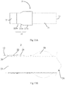
- the difference from the luminal stent graft of the first embodiment is that the tube orifice, which is close to the proximal end 23, of a second tubular body 22 of a luminal stent graft 2 according to the second embodiment is sealingly connected with the peripheral surface of a first tubular body 21, thus forming a closed tube orifice, and the tube orifice, which is close to the distal end 24, of the second tubular body 22 is open.
- the second tubular body 22 is located near to the proximal end 23 of the first tubular body 21, but persons skilled in the art should know that this figure is only used as an example and is not a limitation to the present application. The person skilled in the art can arrange the second tubular body 22 near to the distal end 24 of the first tubular body 21 based on the instruction of the present application.
- the second tubular body 22 may further include a straight tube section 221a, a conical tube section 222a and a connecting section 223a; the connecting section 223a is sealingly connected with the first tubular body 21; the conical tube section 222a is connected with the connecting section 223a and the straight tube section 221a; and the maximum radial length portion of the second tubular body is located in the straight tube section 221 a, so that a second radial supporting structure (which is not shown in the figure) is at least arranged in the straight tube section 221a.
- the second tubular body 22 complies with the deformation of the inner wall of a lumen 12; the connecting section 223a and the conical tube section 222a may possibly form a clearance 20 together with the inner wall of the lumen 12 as their radial lengths are relatively small; the straight tube section 221 a has a relatively large radial length, and may be completely attached to the inner wall of the lumen 12 through the second radial supporting structure; if the shape of a certain position, where the straight tube section 221a is implanted, on the wall of the lumen 12 is not smooth, the straight tube section 221a may comply with the shape deformation, but other portions of the straight tube section 221a still may be attached to the inner wall of the lumen 12 by their radial expandability.
- the portion, which is attached into the lumen 12, of the straight tube section 221a will prevent further inflow of the blood by its radial supporting force, and the blood left in all the above-mentioned clearances are thrombosed, and then forms a seal, thereby cutting off a channel or an opening that may form type-I endoleak and avoiding the blood from flowing into a tumor body or a dissection 18.
- the difference from the luminal stent graft of the second embodiment is that two tube orifices of a second tubular body 22 of a luminal stent graft 2 according to the third embodiment are both sealingly connected with the peripheral surface of a first tubular body 21, thus forming two closed tube orifices.
- this luminal stent graft is similar to that of the second embodiment, and similarly, after implantation, a channel or an opening that may form type-I endoleak also may be cut off.
- sealing In this sealing process, no other sealing or filling materials need to be added into the luminal stent graft 2 in advance or after the luminal stent graft 2 is implanted, but sealing may be realized only through inflowing blood from normal blood circulation, so that no extra biological risk caused by the sealing or filling materials will be added.
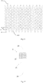
- a luminal stent graft of the fourth embodiment is approximately the same as the luminal stent graft of the first embodiment, but the difference is that a second radial supporting structure includes a meshed structure, for example a woven meshed structure or a cut meshed structure.
- a second radial supporting structure includes a meshed structure, for example a woven meshed structure or a cut meshed structure.
- the radial supporting structure of a second tubular body 22 includes the woven meshed structure; and with reference to Figure 16 , the radial supporting structure of the second tubular body 22 includes the cut meshed structure.
- the second radial supporting structure 221 includes the cut meshed structure which has multiple grids 2224.
- the meshed structure may be formed by cutting a metal net tube, for example it may be integrally formed by carrying out laser cutting on a memory alloy (including a nickel-titanium alloy) net tube, and the metal net tube may be 0.05 mm to 0.4 mm in thickness.
- the diameter of each of connecting rods 2225 forming the grids 2224 in an encircling manner may be 0.05 mm to 0.4 mm.
- the diameter of each connecting rod 2225 is 0.05 mm to 0.32 mm; when the radial length of the second radial supporting structure 221 is 20 mm to 50 mm, the diameter of each connecting rod 2225 is 0.1 mm to 0.35 mm; and when the radial length of the second radial supporting structure 221 is 50 to 80 mm, the diameter of each connecting rod 2225 is 0.2 mm to 0.4 mm.
- a metal wire within the above-mentioned wire diameter range has relatively high bending flexibility, a waveform ring-like object formed by winding the metal wire has relatively high radial deformability.
- the maximum width m1 of any grid 2224 formed by cutting and the perimeter D of the second tubular body 22 at this grid 2224 meets a condition that m1 is less than or equal to D/12.
- the maximum width m1 and the perimeter D meets the condition that m1 is less than or equal to D/12, and m1 ranges from 1.5 mm to 5 mm.
- the maximum width m1 and the perimeter D meets a condition that m1 is less than or equal to D/13, and m1 ranges from 1.5 mm to 7 mm.
- the maximum width m1 and the perimeter D meets a condition that m1 is less than or equal to D/14, and m1 ranges from 1.5 mm to 8 mm. If m1 is smaller, the filling effect is better.
- the maximum length of the above-mentioned grid along an axial direction is 4 mm to 16 mm.
- the maximum length of the grid along the axial direction is 4 mm to 12 mm.
- the maximum length of the grid along the axial direction is 6 mm to 14 mm.
- the maximum length of the grid along the axial direction is 8 mm to 16 mm.
- At least one grid 2224 of the meshed structure has an internal fillet 2222, the maximum width n1 of the internal fillet 2222 along the circumferential direction meets a condition that n1 is less than or equal to 1.5 mm. If the value of n1 is smaller, the deformability of the second tubular body 22 for complying with the inner wall of the lumen is higher, and the clearance filling capacity is higher, so that the capacity of blocking the endoleak is higher.
- the fifth embodiment provides a luminal stent graft system.
- the luminal stent graft system includes at least one luminal stent graft 2 according to any one of embodiments 1 to 4, wherein multiple luminal stent grafts 2 may be implanted into a lumen cooperatively, or one or multiple luminal stent grafts 2 and other existing luminal stent grafts which do not have second radial supporting structures are implanted into the lumen cooperatively.
- the luminal stent grafts 2 are collectively called a first luminal stent graft 2 below, and the other existing luminal stent grafts which do not have the second radial supporting structures may be collectively called a second luminal stent graft 3.
- one conventional second luminal stent graft 3 and one first luminal stent graft 2 according to the embodiment of the present application may be cooperatively applied to a chimney technology, or a periscope technology, or a sandwich technology.
- one conventional second luminal stent graft 3 and two first luminal stent grafts 2 according to the embodiments of the present application may be cooperatively applied to an abdominal aorta, wherein the second luminal stent graft 3 is implanted into the abdominal aorta, and the two first luminal stents 2 are respectively implanted into a renal artery.
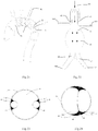
- the aorta arch 191 generally has three branch blood vessels, for example, a blood flow channel may be rebuilt at this position by adopting the chimney technology.
- An arrow in the figure is a blood flow direction, and it has been defined that the blood flow flows from the proximal end to the distal end in the above contents.
- first luminal stent graft 2 is a luminal stent graft which has a first tubular body 21 and a second tubular body 22 according to the embodiment of the present application
- the second luminal stent graft 3 may be one of the first luminal stent graft 2, and also may be an existing luminal stent graft which does not have a second radial supporting structure.
- the second luminal stent graft 3 is a conventional stent graft, for example, it is may be a straight tubular stent graft.
- the distal end of the first luminal stent graft 2 extends into one branch blood vessel, such as a left subclavian artery 192, so that blood can flow into the branch blood vessel from the aorta arch blood vessel 191 through the first luminal stent graft 2, thus rebuilding a branch blood vessel channel.
- Figure 20 shows the first luminal stent graft 2 including the first tubular body 21 and the second tubular body 22, wherein the second tubular body 22 covers part of a proximal end region of the first tubular body 21, but does not cover the proximal end face of the first tubular body 21; and the specific structure of the first luminal stent graft 2 is as shown in Figure 3 .
- the proximal end of the first luminal stent graft 2 and the proximal end of the second luminal stent graft 3 are arranged side by side; the proximal end face of the second tubular body 22 is basically flush with the proximal end face of the second luminal stent 3; and the first tubular body 21 relatively extends and protrudes towards the proximal end.
- the first luminal stent graft 2 and the proximal end region of the second luminal stent graft 3 radially press each other in the aorta arch blood vessel 191; in the radial supporting section, the second luminal stent graft 3 serving as a main body stent complies with the deformation under the pressure of the first luminal stent graft 2 serving as a branch stent graft; to guarantee unblocked blood flow in the branch blood vessel, the first tubular body 21 of the first luminal stent graft 2 has relatively high radial supporting force, and may avoid lumen loss in a pressing process; and the second tubular body 22 may simultaneously comply with the shape deformation of the lumen wall and the shape deformation of the second luminal stent graft 3 due to its relatively low radial supporting force, thereby forming a clearance 20 between the first tubular body 21 and the second tub
- a type-I endoleak channel between the main body stent graft and the branch stent graft in the prior art is filled with the clearance 20; as one end of the clearance 20 is open, and the other end of the clearance 20 is closed, blood flow flowing into the clearance 20 may be used as a sealing and filling material for plugging the type-I endoleak channel to avoid the blood flow from entering a tumor body or a dissection; and the second tubular body 22 is unblocked, so that the blood flow can successfully flow into the branch blood vessel.
- the blood vessel channel may be rebuilt by adopting the periscope technology.
- the distal end of the second luminal stent graft 3 serving as the main body stent graft and the proximal end of the first luminal stent graft 2 serving as the branch stent graft may be arranged side by side; an arrow in the figure shows a blood flow direction; for a single luminal stent graft here, blood always flows from the proximal end of the luminal stent graft to the distal end.
- the first luminal stent graft 2 includes a first tubular body 21 and a second tubular body 22; the second tubular body 22 covers part of a proximal end region of the first tubular body 21, but does not cover the proximal end face of the first tubular body 21.
- the proximal end of the first luminal stent graft 2 and the distal end of the second luminal stent graft 3 are arranged side by side; the proximal end face of the second tubular body 22 is basically flush with the distal end face of the second luminal stent graft 3; and the first tubular body 21 extends and protrudes relative to the second tubular body 22.
- a semi-closed clearance (which is not shown in the figure) is formed among the distal end of the second luminal stent graft 3, the first tubular body 21, the second tubular body 22 and the lumen wall, and a semi-closed clearance (which is not shown in the figure) is also formed between the first tubular body 21 and the second tubular body 22, thereby preventing the generation of a type-I endoleak channel and avoiding blood from flowing into a tumor body or a dissection.
- the blood flow may inversely enter the proximal end of the first luminal stent graft 2 from the distal end of the second luminal stent graft 3, as shown in the arrow A. Also, in this case, the blood flow generates relatively low impact force on the semi-closed clearance, thus further preventing the formation of type-I endoleak.
- the luminal stent graft according to the embodiment of the present application also may be applied to an abdominal aorta 193. If the stent graft is implanted into the abdominal aorta 193, two branch blood vessels at a renal artery and/or an iliac artery should be considered according to the shape of a tumor body or a dissection 18.
- An arrow in the figure is a blood flow direction, and it has been defined above that for a single luminal stent graft, blood flow flows from the proximal end to the distal end.
- first luminal stent grafts 42 and 43 and one second luminal stent 41 may be adopted for cooperative implantation, wherein the first luminal stent grafts 42 and 43 are luminal stent grafts having first tube bodies and second tube bodies according to the embodiments of the present application, and the second luminal stent graft 41 may be a luminal stent graft which is of the same type as the first luminal stent grafts 42 and 43 or may be a different luminal stent graft.
- the second luminal stent graft 41 is a conventional stent graft, such as a straight tubular stent graft.
- the two first luminal stent grafts 42 and 43 and the one second luminal stent graft 41 are implanted cooperatively; directions of openings in the proximal ends of the two first luminal stent grafts 42 and 43 and the proximal end of the second luminal stent graft 41 are consistent, and the first luminal stent grafts 42 and 43 and the second luminal stent graft 41 are arranged in the abdominal aorta blood vessel 193 side by side; the distal end of each of the two first luminal stent grafts 42 and 43 extends into one branch blood vessel respectively, namely the right renal artery 194 or the left renal artery 195, so that blood may flow into the branch blood vessels from the abdominal aorta blood vessel 193 through the first luminal stent grafts 42 and 43.
- the first luminal stent graft 42 includes a first tubular body 421 and a second tubular body 422; the second tubular body 422 covers part of a proximal end region of the first tubular body 421, but does not cover the proximal end face of the first tubular body 421.
- the proximal end of the first luminal stent graft 42 and the proximal end of the second luminal stent 41 are arranged side by side; the proximal end face of the second tubular body 422 is basically flush with the proximal end face of the second luminal stent graft 41; and the first tubular body 421 relatively extends and protrudes towards the proximal end.
- the first luminal stent graft 43 includes a first tubular body 431 and a second tubular body 432; the second tubular body 432 covers part of a proximal end region of the first tubular body 431, but does not cover the proximal end face of the first tubular body 431.
- the proximal end of the first luminal stent graft 43 and the proximal end of the second luminal stent graft 41 are arranged side by side; the proximal end face of the second tubular body 43 is basically flush with the proximal end face of the second luminal stent graft 41; and the first tubular body 431 relatively extends and protrudes towards the proximal end.
- the first luminal stent graft 42 and the proximal end region of the second luminal stent graft 41 radially press each other in the abdominal aorta blood vessel 193; in the radial supporting section, the second luminal stent graft 41 serving as a main body stent graft complies with the deformation under the pressure of the first luminal stent graft 42 serving as a branch stent graft; to guarantee unblocked blood flow in the branch blood vessel, the first tubular body 421 of the first luminal stent 42 has a relatively high radial supporting force, and may avoid lumen loss in a pressing process; and the second tubular body 422 may simultaneously comply with the shape deformation of the lumen wall and the shape deformation of the second luminal stent graft 41 due to its relatively low radial supporting force, thereby forming
- a type-I endoleak channel between the main body stent and the branch stent in the prior art is filled with the clearance 420; as one end of the clearance 420 is open, and the other end of the clearance 420 is closed, blood flow flowing into the clearance 420 may be used as a sealing and filling material for plugging the type-I endoleak channel; and the second tubular body 422 is unblocked, so that the blood flow may successfully flow into the branch blood vessel.
- a clearance 430 may be also formed between the first tubular body 431 and the second tubular body 432 of the first luminal stent graft 43, and the type-I endoleak channel between the main body stent graft and the branch stent graft in the prior art is filled with the clearance 430.
- the two first luminal stent grafts 44 and 45 are implanted cooperatively; directions of openings in the proximal ends of the two first luminal stent grafts 44 and 45 are consistent, and the first luminal stent grafts 44 and 45 are arranged in the abdominal aorta blood vessel 193 side by side; the distal end of each of the two first luminal stent grafts 44 and 45 extends into one branch blood vessel respectively, namely the right iliac artery 196 or the left iliac artery 197, so that blood may flow into the branch blood vessels 196 and 197 from the abdominal aorta blood vessel 193 through the first luminal stent grafts 44 and 45.
- the first luminal stent graft 44 includes a first tubular body 441 and a second tubular body 442; the second tubular body 442 covers part of a proximal end region of the first tubular body 441, but does not cover the proximal end face of the first tubular body 441.
- the first luminal stent 45 includes a first tubular body 451 and a second tubular body 452; the second tubular body 452 covers part of a proximal end region of the first tubular body 451, but does not cover the proximal end face of the first tubular body 451.
- the proximal ends of the two first luminal stent grafts 44 and 45 are arranged side by side, and their proximal end faces are basically flush with each other, for example, the proximal end faces of the two first tube bodies 441 and 451 are basically flush with each other, and/or the proximal end faces of the two second tube bodies 442 and 452 are basically flush with each other.
- the two first luminal stent grafts 44 and 45 radially press each other in the abdominal aorta blood vessel 193; in the radial supporting section, the two first tubular bodies 441 and 451 deform little due to their relatively high radial supporting forces, and the two second tubular bodies 442 and 452 may comply with the shape deformation of the lumen wall and the shape deformation of the first tubular bodies due to relatively low radial supporting force, thereby forming clearances, such as clearances 440 and 450, between the corresponding first tubular bodies and the corresponding second tubular bodies.
- blood flow flowing into the clearance may be used as a sealing and filling material for plugging a type-I endoleak channel to avoid the blood from flowing into the a tumor body or a dissection and ensure that the blood flow may successfully flow into the two first tubular bodies.
- a luminal stent graft 2 according to the seventh embodiment of the present application is approximately similar to the luminal stent graft 2 of the first embodiment of the present application, and includes a first tubular body 21 and a second tubular body 22.
- the second tubular body 22 is sleeved outside the first tubular body 21, and covers at least one portion of the first tubular body 21; and one end of the second tubular body 22 is sealingly connected with the peripheral surface of the first tubular body 21.
- each end of the first tubular body 21 of the seventh embodiment has multiple convex pieces 27 extending in parallel to the longitudinal axis of the first tubular body 21, and a gap 28 is reserved between two adjacent convex pieces 27.
- the convex pieces 27 may be formed in a way of, for example, removing the graft between two adjacent wave crests in a wave loop, which is closest to the end portion of the first tubular body 21, of the first tubular body 21 in the first embodiment.
- the wave loop in the present application is a waveform ring-like object surrounding the longitudinal central axis of the first tubular body 21.
- the luminal stent graft 2 in this embodiment is implanted into a human body by adopting a method as shown in Figure 19 , Figure 21 or Figure 22 , even if the side wall of the blood flow inlet end of the first tubular body 21 in this embodiment is gathered together into the lumen in a blood vessel due to the pressure applied by the main body stent graft and the vascular wall, the blood flow also may flow into the first tubular body 21 from the gap 28 between the two convex pieces 27 at the blood flow inlet end of the first tubular body 21 in this embodiment, thereby avoiding the risk that the blood flow may not enter a corresponding branch blood vessel from the blood flow inlet end of the first tubular body which is closed by the pressure of the main body stent graft and the vascular wall, and improving the safety and the effectiveness of the operation.
- a hole is formed in the graft (for example: the graft between the first wave loop counted from left to right and the blood flow inlet end or the graft between the first wave loop counted from left to right and the second wave loop) near to the blood flow inlet end (namely the left side end of the first tubular body 21 in Figure 3 ) of the first tubular body 21 as shown in Figure 3 , and penetrates through the overlay film, or the first wave loop, which is close to the blood flow inlet end (namely the left side end of the first tubular body 21 in Figure 3 ), of the first tubular body 21 as shown in Figure 3 is not completely covered by the graft (namely multiple wave crests, which face to the left side, of the first wave loop counted from left to right are exposed); and it also ensures that even under a condition that an inlet of the blood flow inlet end is blocked by a blood vessel, there is still a blood flow flowing towards a branch blood vessel through the first tubular
- the second tubular body 22 in this embodiment is the same as the second tubular body 22 in the first embodiment, and the first tubular body 21 in this embodiment is approximately similar to the first tubular body 21 in the first embodiment, but the difference only lies in: two ends of the first tubular body 21 in this embodiment have multiple convex pieces 27, that is to say, the first tubular body 21 in this embodiment may be obtained by removing the graft between every two adjacent wave crests in a wave loop, which is closest to the corresponding end portion, at each of two ends of the first tubular body 21 in the first embodiment, namely the luminal stent graft 2 in this embodiment may be obtained by removing the film between every two adjacent wave crests in the wave loop, which is closest to the corresponding end portion, at each end of the first tubular body 21 of the luminal stent graft
- multiple convex pieces 27 may be only formed at the blood flow inlet end of the first tubular body 21. That is to say, no convex pieces 27 are arranged at the blood flow outlet end of the first tubular body 21.
- the graft between one pair of adjacent wave crests in a wave loop, which is closest to the blood flow inlet end, of the first tubular body 21 in the first embodiment may not be removed according to a requirement as long as the graft between at least two pairs of adjacent wave crests in the multiple wave crests are removed to form the multiple convex pieces.
- a luminal stent graft 2 according to the eighth embodiment of the present application is approximately similar to the luminal stent graft 2 according to the seventh embodiment of the present application, and includes a first tubular body 21 and a second tubular body 22.
- the second tubular body 22 is sleeved outside the first tubular body 21, and covers at least one portion of the first tubular body 21; and one end of the second tubular body 22 is sealingly connected with the peripheral surface of the first tubular body 21.
- each turn of wave loop 23 of the first tubular body 21 in this embodiment is arranged between one annular outer graft 219 and one barrel-shaped inner graft 210 in a clamping manner; moreover, the wave crests of each wave loop 218 are exposed outside, and the wave troughs of each wave loop 218 are all wrapped by the corresponding annular outer graft 219 and the corresponding barrel-shaped inner graft 210 (with reference to Figure 27 and Figure 28 ).
- the annular outer graft 219 and the barrel-shaped inner graft 210 may be PET (polyethylene terephthalate) films or PTFE (polytetrafluoroethylene) films, and may clamp the wave loops of the first tubular body 21 by suturing or hot melting.
- PET polyethylene terephthalate
- PTFE polytetrafluoroethylene
- the wave crests of each wave loop may be separated from the annular outer graft 219 and the barrel-shaped inner graft 210 (that is to say, the wave crests of each wave loop may be up-warped relative to the annular outer graft 219 and the barrel-shaped inner graft 210); therefore, when the first tubular body 21 is bent, on the lesser curvature side, in two adjacent wave loops, one wave loop may be overlapped with the other wave loop, thereby improving the softness of the first tubular body 21.
- the lesser curvature side is the side having a small bending radius when the first tubular body 21 is bent.
- the wave crests on the lesser curvature side of the first tubular body 21 also may be only exposed to achieve the aim of the present application.
- a luminal stent graft 2 according to the ninth embodiment of the present application is approximately similar to the luminal stent graft 2 according to the seventh embodiment of the present application, and includes a first tubular body 21 and a second tubular body 22.
- the second tubular body 22 is sleeved outside the first tubular body 21, and covers at least one portion of the first tubular body 21; and one end of the second tubular body 22 is sealingly connected with the peripheral surface of the first tubular body 21.
- each turn of wave loop 218 of the first tubular body 21 in this embodiment is arranged between one annular outer graft 219 and one barrel-shaped inner graft 210 in a clamping manner, and the annular outer graft 219 is located between the wave crests and the wave troughs of the wave loop 218 clamped by it; and the wave crests and the wave troughs of the wave loop 218 are all exposed outside.
- the annular outer graft 219 and the barrel-shaped inner graft 210 may be PET films or PTFE films, and may clamp the wave loops of the first tubular body 21 by suturing or hot melting.
- the wave crests and the wave troughs of each wave loop may be separated from the annular outer graft 219 and the barrel-shaped inner graft 210 (that is to say, the wave crests and the wave troughs of each wave loop may be all up-warped relative to the annular outer graft 219 and the barrel-shaped inner graft 210).
- one wave loop may be overlapped with the other wave loop, thereby improving the softness of the first tubular body 21.
- it is precisely because the wave crests and the wave troughs of the wave loops are exposed outside that it is difficult for the wave crests or the wave troughs of the wave loops to puncture the barrel-shaped inner graft in the bending process, thus prolonging the service life of the first tubular body 21.
- the width of each annular outer graft 219 along the longitudinal central axial line direction of the first tubular body 21 is greater than or equal to 1/3 of a distance between the wave crests and the wave troughs of the wave loop clamped by the annular outer graft 219 along the longitudinal central axial line direction of the first tubular body 21, and less than or equal to 2/3 of the distance between the wave crests and the wave troughs of the wave loop clamped by the annular outer overlay film 219 along the longitudinal central axial line direction of the first tubular body 21 to ensure that the wave loop may not be separated from the overlay film and the wave crests and the wave troughs of the wave loop are exposed outside.
- the wave crests on the lesser curvature side of the first tubular body 21 also may be only exposed to achieve the aim of the present application.
- a luminal stent graft 2 according to the tenth embodiment of the present application is approximately similar to the luminal stent graft 2 according to the first embodiment of the present application, and includes a first tubular body 21 and a second tubular body 22.
- the second tubular body 22 is sleeved outside the first tubular body 21, and covers at least one portion of the first tubular body 21; and one end of the second tubular body 22 is sealingly connected with the peripheral surface of the first tubular body 21.
- the first tubular body 21 of the tenth embodiment includes barrel-shaped inner graft 210, a first wave loop group 211, a second wave loop group 212, a third wave loop group 213, a fourth wave loop group 214 and annular outer graft 219 arranged on the wave loop groups, wherein the second wave loop group 212 is located between the first wave loop group 211 and the third wave loop group 213; the third wave loop group 213 is located between the second wave loop group 212 and the fourth wave loop group 214; and the four wave loop groups are connected through square connecting rings 215, that is to say, the first wave loop group 211, the second wave loop group 212, the third wave loop group 213 and the fourth wave loop group 214 are arrayed in sequence along the longitudinal central axis direction of the first tubular body 21.
- the annular outer graft 219 and the barrel-shaped inner graft 210 may be PET films or PTFE films, and may clamp the wave loops of the first tubular body 21 by suturing or hot melting. It can be understood that the first wave loop group 211, the second wave loop group 212, the third wave loop group 213 and the fourth wave loop group 214 form one portion of the bare stent of the first tubular body 21.
- the first wave loop group 211 includes a first wave loop 211a, a second wave loop 211b and a third wave loop 211c, which are connected.
- the first wave loop 211a has two adjacent, relatively high wave crests 2111, multiple relatively low wave crests 2112 and multiple wave troughs 2113; the multiple relatively low wave crests 2112 are parallel and level to one another in the longitudinal central axis direction of the first tubular body 21; the multiple wave troughs 2113 are parallel and level to one another in the longitudinal central axis direction of the first tubular body 21; and the multiple relatively low wave crests 2112 are located between the multiple relatively high wave crests 2111 and the multiple wave troughs 2113.
- Multiple wave crests of the second wave loop 211b, multiple wave crests of the third wave loop 211c and the multiple relatively low wave crests 2112 are parallel and level in the longitudinal central axis direction of the first tubular body 21.
- Multiple wave troughs of the second wave loop 211b, multiple wave troughs of the third wave loop 211c and the multiple wave troughs 2113 are parallel and level in the longitudinal central axis direction of the first tubular body 21.
- the second wave loop group 212 includes a first wave loop 212a, a second wave loop 212b and a third wave loop 212c, which are connected.
- the first wave loop 212a has one relatively high wave crest 2121, multiple relatively low wave crests 2122 and multiple wave troughs 2123; the multiple relatively low wave crests 2122 are parallel and level to one another in the longitudinal central axis direction of the first tubular body 21; the multiple wave troughs 2123 are parallel and level to one another in the longitudinal central axis direction of the first tubular body 21; and the multiple relatively low wave crests 2122 are located between the relatively high wave crest 2121 and the multiple wave troughs 2123.
- the relatively high wave crest 2121 is hooked and wound with the wave troughs 2113 between the two adjacent relatively high wave crests 2111 of the first wave loop 211a to form a whole to connect the first wave loop 211a with the first wave loop 212a, namely to connect the first wave loop group 211 with the second wave loop group 212.
- Multiple wave crests of the second wave loop 212b, multiple wave crests of the third wave loop 212c and the multiple relatively low wave crests 2122 are parallel and level in the longitudinal central axis direction of the first tubular body 21.
- Multiple wave troughs of the second wave loop 212b, multiple wave troughs of the third wave loop 212c and the multiple wave troughs 2123 are parallel and level in the longitudinal central axis direction of the first tubular body 21.
- the third wave loop group 213 includes a first wave loop 213a, a second wave loop 213b and a third wave loop 213c, which are connected.
- the first wave loop 213a has two adjacent relatively high wave crest 2131, multiple relatively low wave crests 2132 and multiple wave troughs 2133; the multiple relatively low wave crests 2132 are parallel and level to one another in the longitudinal central axis direction of the first tubular body 21; the multiple wave troughs 2133 are parallel and level to one another in the longitudinal central axis direction of the first tubular body 21; and the multiple relatively low wave crests 2132 are located between the multiple relatively high wave crests 2131 and the multiple wave troughs 2133.
- the wave crest 2131 on the left side is hooked and wound with the wave trough 2113 on the left side, which is closest to the relatively high wave crest 2121 of the first wave loop 212a
- the wave crest 2131 on the right side is hooked and wound with the wave trough 2113 on the right side, which is closest to the relatively high wave crest 2121 of the first wave loop 212a to connect the first wave loop 212a with the first wave loop 213a, namely to connect the second wave loop group 212 with the third wave loop group 213.
- Multiple wave crests of the second wave loop 213b, multiple wave crests of the third wave loop 213c and the multiple relatively low wave crests 2132 are parallel and level in the longitudinal central axis direction of the first tubular body 21.
- Multiple wave troughs of the second wave loop 213b, multiple wave troughs of the third wave loop 213c and the multiple wave troughs 2133 are parallel and level in the longitudinal central axis direction of the first tubular body 21.
- the fourth wave loop group 214 includes a first wave loop 214a, a second wave loop 214b and a third wave loop 214c, which are connected.
- the first wave loop 214a has one relatively high wave crest 2141, multiple relatively low wave crests 2142 and multiple wave troughs 2143; the multiple relatively low wave crests 2142 are parallel and level to one another in the longitudinal central axis direction of the first tubular body 21; the multiple wave troughs 2143 are parallel and level to one another in the longitudinal central axis direction of the first tubular body 21; and the multiple relatively low wave crests 2142 are located between the relatively high wave crest 2141 and the multiple wave troughs 2143.
- the relatively high wave crest 2141 is hooked and wound with the wave troughs 2133 between the two adjacent relatively high wave crests 2131 of the third wave loop 213a to form a whole to connect the third wave loop 213a with the fourth wave loop 212a, namely to connect the first wave loop group 211 with the second wave loop group 212.
- Multiple wave crests of the second wave loop 214b, multiple wave crests of the third wave loop 214c and the multiple relatively low wave crests 2142 are parallel and level in the longitudinal central axis direction of the first tubular body 21.
- the longitudinal central axis directions of the first tubular body 21 ,multiple wave troughs of the second wave loop 214b, multiple wave troughs of the third wave loop 214c and the multiple wave troughs 2143 are parallel and level.
- the first wave loop group 211, the second wave loop group 212, the third wave loop group 213, and the fourth wave loop group 214 are connected into a whole through the square connecting rings 215.
- each wave loop group the second wave loop and/or the third wave loop may be omitted as long as each wave loop group has the first wave loop such that the four wave loop groups may be connected through the square connecting rings. It also can be understood that in the four wave loop groups, or in one, two or three wave loop groups, the second wave loop and/or the third wave loop may be omitted as long as each wave loop group has the first wave loop such that the four first wave loops may be connected through the square connecting rings.
- first wave loop group 211 also may not include the first wave loop and/or the second wave loop, and at the moment, the wave troughs of the third wave loop also may be hooked and wound with the relatively high wave crest of the second wave loop group to connect the first wave loop group with the second wave loop group.
- Each annular outer graft 219 is also arranged on each wave loop group and is located between the wave crests and the wave troughs of the wave loop group clamped by it, and the wave crests and the wave troughs of the wave loop group are all exposed outside.
- the wave crests and the wave troughs of each wave loop may be separated from the annular outer graft 219 and the barrel-shaped inner graft 210 (that is to say, the wave crests and the wave troughs of each wave loop may be all up-warped relative to the annular outer graft 219 and the barrel-shaped inner graft 210); therefore, when the first tubular body 21 is bent, on the lesser curvature side, in two adjacent wave loop groups, one wave loop group may be overlapped with the other wave loop group, thereby improving the softness of the first tubular body 21.
- the bare stent of the first tubular body also may include a first wave loop group, a second wave loop group, a third wave loop group and a fourth wave loop group which are connected through square connecting rings.
- the luminal stent graft includes the first tubular body and the second tubular body which covers at least one part of the radial supporting section of the first tubular body; after the luminal stent graft is implanted, the semi-closed clearance may be formed between the first tubular body and the second tubular body, or the semi-closed clearance may be formed between the second tubular body or the lumen wall; and the blood flowing into the clearance may be used as the filling material to plug the type-I endoleak channel, thus avoiding the blood from flowing into the tumor body or the dissection.
Landscapes
- Health & Medical Sciences (AREA)
- Engineering & Computer Science (AREA)
- Biomedical Technology (AREA)
- Heart & Thoracic Surgery (AREA)
- Public Health (AREA)
- Transplantation (AREA)
- Cardiology (AREA)
- Veterinary Medicine (AREA)
- Oral & Maxillofacial Surgery (AREA)
- Vascular Medicine (AREA)
- Life Sciences & Earth Sciences (AREA)
- Animal Behavior & Ethology (AREA)
- General Health & Medical Sciences (AREA)
- Gastroenterology & Hepatology (AREA)
- Pulmonology (AREA)
- Prostheses (AREA)
- Media Introduction/Drainage Providing Device (AREA)
Applications Claiming Priority (2)
| Application Number | Priority Date | Filing Date | Title |
|---|---|---|---|
| CN201511027977.3A CN105496603B (zh) | 2015-12-30 | 2015-12-30 | 管腔支架 |
| PCT/CN2016/111686 WO2017114302A1 (zh) | 2015-12-30 | 2016-12-23 | 管腔支架 |
Publications (3)
| Publication Number | Publication Date |
|---|---|
| EP3398564A1 true EP3398564A1 (de) | 2018-11-07 |
| EP3398564A4 EP3398564A4 (de) | 2019-08-14 |
| EP3398564B1 EP3398564B1 (de) | 2022-10-05 |
Family
ID=55705173
Family Applications (1)
| Application Number | Title | Priority Date | Filing Date |
|---|---|---|---|
| EP16881091.9A Active EP3398564B1 (de) | 2015-12-30 | 2016-12-23 | Luminaler stent |
Country Status (6)
| Country | Link |
|---|---|
| US (1) | US10624768B2 (de) |
| EP (1) | EP3398564B1 (de) |
| CN (1) | CN105496603B (de) |
| ES (1) | ES2928776T3 (de) |
| PL (1) | PL3398564T3 (de) |
| WO (1) | WO2017114302A1 (de) |
Cited By (1)
| Publication number | Priority date | Publication date | Assignee | Title |
|---|---|---|---|---|
| EP3733135A4 (de) * | 2017-12-28 | 2021-10-20 | Kawasumi Laboratories, Inc. | Rohrförmiges implantat und vorrichtung zum implantieren eines rohrförmigen implantats |
Families Citing this family (30)
| Publication number | Priority date | Publication date | Assignee | Title |
|---|---|---|---|---|
| US10736730B2 (en) | 2015-01-20 | 2020-08-11 | Neurogami Medical, Inc. | Vascular implant |
| US10925611B2 (en) | 2015-01-20 | 2021-02-23 | Neurogami Medical, Inc. | Packaging for surgical implant |
| US20200138422A1 (en) * | 2015-01-20 | 2020-05-07 | Neurogami Medical, Inc. | Vascular implant |
| KR102932021B1 (ko) * | 2015-11-12 | 2026-02-27 | 바이오스테이지, 인크. | 문합 또는 다른 생리학적 위치에서 위장 조직을 생성하기 위한 시스템 및 방법 |
| CN109077836B (zh) * | 2015-12-30 | 2021-01-22 | 先健科技(深圳)有限公司 | 管腔支架 |
| CN105496603B (zh) | 2015-12-30 | 2018-11-06 | 先健科技(深圳)有限公司 | 管腔支架 |
| CN107822739B (zh) * | 2016-09-07 | 2020-03-24 | 先健科技(深圳)有限公司 | 管腔支架及管腔支架系统 |
| US11583383B2 (en) | 2016-12-28 | 2023-02-21 | Lifetech Scientific (Shenzhen) Co. Ltd. | Luminal stent |
| CN119235502B (zh) * | 2017-08-28 | 2025-11-25 | 先健科技(深圳)有限公司 | 管腔支架 |
| CN109966034B (zh) * | 2017-12-27 | 2021-08-17 | 先健科技(深圳)有限公司 | 覆膜支架 |
| CN109966033B (zh) * | 2017-12-28 | 2022-05-20 | 先健科技(深圳)有限公司 | 管腔支架 |
| CN109984864B (zh) * | 2017-12-29 | 2020-07-17 | 先健科技(深圳)有限公司 | 用于分支血管的支架 |
| CN109984863B (zh) * | 2017-12-29 | 2020-04-07 | 先健科技(深圳)有限公司 | 双层血管支架 |
| CN111228002B (zh) * | 2018-11-13 | 2022-05-03 | 深圳市先健畅通医疗有限公司 | 管腔支架 |
| CN111228001B (zh) * | 2018-11-13 | 2022-05-03 | 深圳市先健畅通医疗有限公司 | 管腔支架及原位开窗支架系统 |
| CN109730804B (zh) * | 2018-12-05 | 2021-02-26 | 深圳市先健畅通医疗有限公司 | 覆膜支架 |
| CN109806039B (zh) * | 2018-12-26 | 2020-10-13 | 中国人民解放军陆军军医大学第一附属医院 | 覆膜支架及覆膜支架置于血管内的方法 |
| US11998442B2 (en) * | 2018-12-28 | 2024-06-04 | Lifetech Scientific (Shenzhen) Co., Ltd. | Covered stent and preparation method therefor |
| CN109700570B (zh) * | 2018-12-28 | 2020-04-10 | 深圳市先健畅通医疗有限公司 | 覆膜支架 |
| CN109700569B (zh) * | 2018-12-28 | 2020-11-17 | 深圳市先健畅通医疗有限公司 | 覆膜支架及其制备方法 |
| CN109700568B (zh) * | 2018-12-28 | 2020-06-12 | 深圳市先健畅通医疗有限公司 | 覆膜支架 |
| DE102019115021A1 (de) | 2019-06-04 | 2020-12-10 | Bentley Innomed Gmbh | Stentgraft mit Dichtungselement |
| CN113081387B (zh) * | 2019-12-23 | 2023-12-05 | 先健科技(深圳)有限公司 | 覆膜支架、覆膜支架输送系统及覆膜支架的装载方法 |
| CN111067668B (zh) * | 2019-12-27 | 2022-04-22 | 先健科技(深圳)有限公司 | 测力装置 |
| CN111407463B (zh) * | 2020-03-19 | 2022-08-12 | 湖南埃普特医疗器械有限公司 | 一种覆膜支架系统 |
| WO2021190542A1 (zh) * | 2020-03-26 | 2021-09-30 | 深圳市先健畅通医疗有限公司 | 支架输送器及支架输送系统 |
| CN112603591B (zh) * | 2020-12-01 | 2022-12-02 | 深圳市先健畅通医疗有限公司 | 覆膜支架 |
| CN113558709B (zh) * | 2021-09-22 | 2021-12-28 | 北京华脉泰科医疗器械股份有限公司 | 支架锚定区下移装置 |
| CN118267148A (zh) * | 2022-12-30 | 2024-07-02 | 先健科技(深圳)有限公司 | 双层管腔支架 |
| CN118058873B (zh) * | 2024-04-22 | 2024-08-23 | 北京华脉泰科医疗器械股份有限公司 | 血管腔内修复平行支架 |
Family Cites Families (19)
| Publication number | Priority date | Publication date | Assignee | Title |
|---|---|---|---|---|
| US6015431A (en) * | 1996-12-23 | 2000-01-18 | Prograft Medical, Inc. | Endolumenal stent-graft with leak-resistant seal |
| US6729356B1 (en) * | 2000-04-27 | 2004-05-04 | Endovascular Technologies, Inc. | Endovascular graft for providing a seal with vasculature |
| US7044962B2 (en) * | 2002-06-25 | 2006-05-16 | Scimed Life Systems, Inc. | Implantable prosthesis with displaceable skirt |
| CN2843384Y (zh) * | 2005-07-12 | 2006-12-06 | 北京有色金属研究总院 | 一种主动脉血管支架 |
| CN201179128Y (zh) * | 2007-06-22 | 2009-01-14 | 先健科技(深圳)有限公司 | 带有夹层的腹动脉分叉血管支架 |
| US20140343602A1 (en) * | 2011-08-19 | 2014-11-20 | Brian J. Cox | Expandable occlusion device and methods |
| WO2013084235A2 (en) * | 2011-12-04 | 2013-06-13 | Endospan Ltd. | Branched stent-graft system |
| US9381101B2 (en) | 2012-04-23 | 2016-07-05 | The Charlotte-Mecklenburg Hospital Authority | Hybrid graft for therapy of aortic pathology and associated method |
| AU2012202565B1 (en) * | 2012-05-02 | 2012-09-13 | Cook Medical Technologies Llc | Stent graft adaptor |
| CN202875531U (zh) * | 2012-10-16 | 2013-04-17 | 高峰 | 主动脉瘤腔内隔绝治疗用人工血管 |
| CN104027152A (zh) | 2013-03-07 | 2014-09-10 | 上海微创医疗器械(集团)有限公司 | 一种新型双层覆膜支架 |
| EP3590477B1 (de) | 2013-03-08 | 2024-05-22 | LimFlow GmbH | Systeme zur bereitstellung oder aufrechterhaltung des flüssigkeitsflusses durch körpergänge |
| US20150073523A1 (en) * | 2013-09-10 | 2015-03-12 | Trivascular, Inc. | Endoleak isolation sleeves and methods of use |
| US9808363B2 (en) * | 2014-09-10 | 2017-11-07 | The Cleveland Clinic Foundation | Frame structures, stent grafts incorporating the same, and methods for extended aortic repair |
| CN104873304B (zh) | 2014-12-19 | 2018-08-21 | 中国人民解放军第二军医大学 | 附优化周向张力海绵结构的防i型内漏支架移植物系统 |
| CN104873241B (zh) | 2014-12-19 | 2018-05-08 | 中国人民解放军第二军医大学 | 附螺旋形绒毛结构的防i型内漏支架移植物系统 |
| CN109077836B (zh) * | 2015-12-30 | 2021-01-22 | 先健科技(深圳)有限公司 | 管腔支架 |
| CN105496603B (zh) * | 2015-12-30 | 2018-11-06 | 先健科技(深圳)有限公司 | 管腔支架 |
| CN205494093U (zh) * | 2015-12-30 | 2016-08-24 | 先健科技(深圳)有限公司 | 管腔支架 |
-
2015
- 2015-12-30 CN CN201511027977.3A patent/CN105496603B/zh active Active
-
2016
- 2016-12-23 US US16/067,362 patent/US10624768B2/en active Active
- 2016-12-23 EP EP16881091.9A patent/EP3398564B1/de active Active
- 2016-12-23 ES ES16881091T patent/ES2928776T3/es active Active
- 2016-12-23 PL PL16881091.9T patent/PL3398564T3/pl unknown
- 2016-12-23 WO PCT/CN2016/111686 patent/WO2017114302A1/zh not_active Ceased
Cited By (1)
| Publication number | Priority date | Publication date | Assignee | Title |
|---|---|---|---|---|
| EP3733135A4 (de) * | 2017-12-28 | 2021-10-20 | Kawasumi Laboratories, Inc. | Rohrförmiges implantat und vorrichtung zum implantieren eines rohrförmigen implantats |
Also Published As
| Publication number | Publication date |
|---|---|
| ES2928776T3 (es) | 2022-11-22 |
| EP3398564B1 (de) | 2022-10-05 |
| WO2017114302A1 (zh) | 2017-07-06 |
| CN105496603B (zh) | 2018-11-06 |
| US10624768B2 (en) | 2020-04-21 |
| PL3398564T3 (pl) | 2022-12-19 |
| EP3398564A4 (de) | 2019-08-14 |
| CN105496603A (zh) | 2016-04-20 |
| US20190015227A1 (en) | 2019-01-17 |
Similar Documents
| Publication | Publication Date | Title |
|---|---|---|
| EP3398564B1 (de) | Luminaler stent | |
| EP3398565B1 (de) | Lumenstent | |
| JP2023075324A (ja) | ステント部材 | |
| CA2235911C (en) | Stent and stent-graft for treating branched vessels | |
| EP3068339B1 (de) | Endovaskuläre stentprothese mit einem ermüdungsbeständigen lateralrohr | |
| CN102307548B (zh) | 支架 | |
| EP2409670B1 (de) | Prothese | |
| EP1613242B1 (de) | Vorrichtungen zur Behandlung von Bauchaortenaneurysmen | |
| CN108095858B (zh) | 防短缩覆膜支架及其制作方法 | |
| US9993329B2 (en) | Stent and stent graft prosthesis | |
| US20180333251A1 (en) | Stent-grafts systems with skirt | |
| US10772747B2 (en) | Vascular implant with asymmetrical stent springs | |
| GB2517689A (en) | Stent-Graft | |
| CN205494093U (zh) | 管腔支架 | |
| JP2022500134A (ja) | 膨張式充填構造体及び充填可能カフを有するステントグラフトシステム及び方法 | |
| CN205458864U (zh) | 管腔支架 | |
| CN116407338A (zh) | 血管支架及支架系统 | |
| CN109984865B (zh) | 降低破口压力的覆膜支架 | |
| EP4618914A1 (de) | Selbstexpandierbarer stent | |
| CN116747060B (zh) | 血管瘤腔内假体 | |
| CN210112754U (zh) | 植入物 |
Legal Events
| Date | Code | Title | Description |
|---|---|---|---|
| STAA | Information on the status of an ep patent application or granted ep patent |
Free format text: STATUS: THE INTERNATIONAL PUBLICATION HAS BEEN MADE |
|
| PUAI | Public reference made under article 153(3) epc to a published international application that has entered the european phase |
Free format text: ORIGINAL CODE: 0009012 |
|
| STAA | Information on the status of an ep patent application or granted ep patent |
Free format text: STATUS: REQUEST FOR EXAMINATION WAS MADE |
|
| 17P | Request for examination filed |
Effective date: 20180724 |
|
| AK | Designated contracting states |
Kind code of ref document: A1 Designated state(s): AL AT BE BG CH CY CZ DE DK EE ES FI FR GB GR HR HU IE IS IT LI LT LU LV MC MK MT NL NO PL PT RO RS SE SI SK SM TR |
|
| AX | Request for extension of the european patent |
Extension state: BA ME |
|
| DAV | Request for validation of the european patent (deleted) | ||
| DAX | Request for extension of the european patent (deleted) | ||
| A4 | Supplementary search report drawn up and despatched |
Effective date: 20190715 |
|
| RIC1 | Information provided on ipc code assigned before grant |
Ipc: A61F 2/07 20130101AFI20190709BHEP Ipc: A61F 2/852 20130101ALN20190709BHEP |
|
| REG | Reference to a national code |
Ref country code: DE Ref legal event code: R079 Ref document number: 602016075521 Country of ref document: DE Free format text: PREVIOUS MAIN CLASS: A61F0002820000 Ipc: A61F0002070000 |
|
| GRAP | Despatch of communication of intention to grant a patent |
Free format text: ORIGINAL CODE: EPIDOSNIGR1 |
|
| STAA | Information on the status of an ep patent application or granted ep patent |
Free format text: STATUS: GRANT OF PATENT IS INTENDED |
|
| RIC1 | Information provided on ipc code assigned before grant |
Ipc: A61F 2/852 20130101ALN20220405BHEP Ipc: A61F 2/07 20130101AFI20220405BHEP |
|
| RIC1 | Information provided on ipc code assigned before grant |
Ipc: A61F 2/852 20130101ALN20220419BHEP Ipc: A61F 2/07 20130101AFI20220419BHEP |
|
| INTG | Intention to grant announced |
Effective date: 20220511 |
|
| GRAS | Grant fee paid |
Free format text: ORIGINAL CODE: EPIDOSNIGR3 |
|
| GRAA | (expected) grant |
Free format text: ORIGINAL CODE: 0009210 |
|
| STAA | Information on the status of an ep patent application or granted ep patent |
Free format text: STATUS: THE PATENT HAS BEEN GRANTED |
|
| AK | Designated contracting states |
Kind code of ref document: B1 Designated state(s): AL AT BE BG CH CY CZ DE DK EE ES FI FR GB GR HR HU IE IS IT LI LT LU LV MC MK MT NL NO PL PT RO RS SE SI SK SM TR |
|
| REG | Reference to a national code |
Ref country code: GB Ref legal event code: FG4D |
|
| REG | Reference to a national code |
Ref country code: CH Ref legal event code: EP |
|
| REG | Reference to a national code |
Ref country code: AT Ref legal event code: REF Ref document number: 1522282 Country of ref document: AT Kind code of ref document: T Effective date: 20221015 |
|
| REG | Reference to a national code |
Ref country code: DE Ref legal event code: R096 Ref document number: 602016075521 Country of ref document: DE |
|
| REG | Reference to a national code |
Ref country code: IE Ref legal event code: FG4D |
|
| REG | Reference to a national code |
Ref country code: ES Ref legal event code: FG2A Ref document number: 2928776 Country of ref document: ES Kind code of ref document: T3 Effective date: 20221122 |
|
| REG | Reference to a national code |
Ref country code: GR Ref legal event code: EP Ref document number: 20220402121 Country of ref document: GR Effective date: 20221212 |
|
| REG | Reference to a national code |
Ref country code: LT Ref legal event code: MG9D |
|
| REG | Reference to a national code |
Ref country code: NL Ref legal event code: MP Effective date: 20221005 |
|
| REG | Reference to a national code |
Ref country code: AT Ref legal event code: MK05 Ref document number: 1522282 Country of ref document: AT Kind code of ref document: T Effective date: 20221005 |
|
| PG25 | Lapsed in a contracting state [announced via postgrant information from national office to epo] |
Ref country code: NL Free format text: LAPSE BECAUSE OF FAILURE TO SUBMIT A TRANSLATION OF THE DESCRIPTION OR TO PAY THE FEE WITHIN THE PRESCRIBED TIME-LIMIT Effective date: 20221005 |
|
| PG25 | Lapsed in a contracting state [announced via postgrant information from national office to epo] |
Ref country code: SE Free format text: LAPSE BECAUSE OF FAILURE TO SUBMIT A TRANSLATION OF THE DESCRIPTION OR TO PAY THE FEE WITHIN THE PRESCRIBED TIME-LIMIT Effective date: 20221005 Ref country code: PT Free format text: LAPSE BECAUSE OF FAILURE TO SUBMIT A TRANSLATION OF THE DESCRIPTION OR TO PAY THE FEE WITHIN THE PRESCRIBED TIME-LIMIT Effective date: 20230206 Ref country code: NO Free format text: LAPSE BECAUSE OF FAILURE TO SUBMIT A TRANSLATION OF THE DESCRIPTION OR TO PAY THE FEE WITHIN THE PRESCRIBED TIME-LIMIT Effective date: 20230105 Ref country code: LT Free format text: LAPSE BECAUSE OF FAILURE TO SUBMIT A TRANSLATION OF THE DESCRIPTION OR TO PAY THE FEE WITHIN THE PRESCRIBED TIME-LIMIT Effective date: 20221005 Ref country code: FI Free format text: LAPSE BECAUSE OF FAILURE TO SUBMIT A TRANSLATION OF THE DESCRIPTION OR TO PAY THE FEE WITHIN THE PRESCRIBED TIME-LIMIT Effective date: 20221005 Ref country code: AT Free format text: LAPSE BECAUSE OF FAILURE TO SUBMIT A TRANSLATION OF THE DESCRIPTION OR TO PAY THE FEE WITHIN THE PRESCRIBED TIME-LIMIT Effective date: 20221005 |
|
| PG25 | Lapsed in a contracting state [announced via postgrant information from national office to epo] |
Ref country code: RS Free format text: LAPSE BECAUSE OF FAILURE TO SUBMIT A TRANSLATION OF THE DESCRIPTION OR TO PAY THE FEE WITHIN THE PRESCRIBED TIME-LIMIT Effective date: 20221005 Ref country code: LV Free format text: LAPSE BECAUSE OF FAILURE TO SUBMIT A TRANSLATION OF THE DESCRIPTION OR TO PAY THE FEE WITHIN THE PRESCRIBED TIME-LIMIT Effective date: 20221005 Ref country code: IS Free format text: LAPSE BECAUSE OF FAILURE TO SUBMIT A TRANSLATION OF THE DESCRIPTION OR TO PAY THE FEE WITHIN THE PRESCRIBED TIME-LIMIT Effective date: 20230205 Ref country code: HR Free format text: LAPSE BECAUSE OF FAILURE TO SUBMIT A TRANSLATION OF THE DESCRIPTION OR TO PAY THE FEE WITHIN THE PRESCRIBED TIME-LIMIT Effective date: 20221005 |
|
| P01 | Opt-out of the competence of the unified patent court (upc) registered |
Effective date: 20230515 |
|
| REG | Reference to a national code |
Ref country code: DE Ref legal event code: R097 Ref document number: 602016075521 Country of ref document: DE |
|
| PG25 | Lapsed in a contracting state [announced via postgrant information from national office to epo] |
Ref country code: SM Free format text: LAPSE BECAUSE OF FAILURE TO SUBMIT A TRANSLATION OF THE DESCRIPTION OR TO PAY THE FEE WITHIN THE PRESCRIBED TIME-LIMIT Effective date: 20221005 Ref country code: RO Free format text: LAPSE BECAUSE OF FAILURE TO SUBMIT A TRANSLATION OF THE DESCRIPTION OR TO PAY THE FEE WITHIN THE PRESCRIBED TIME-LIMIT Effective date: 20221005 Ref country code: EE Free format text: LAPSE BECAUSE OF FAILURE TO SUBMIT A TRANSLATION OF THE DESCRIPTION OR TO PAY THE FEE WITHIN THE PRESCRIBED TIME-LIMIT Effective date: 20221005 Ref country code: DK Free format text: LAPSE BECAUSE OF FAILURE TO SUBMIT A TRANSLATION OF THE DESCRIPTION OR TO PAY THE FEE WITHIN THE PRESCRIBED TIME-LIMIT Effective date: 20221005 Ref country code: CZ Free format text: LAPSE BECAUSE OF FAILURE TO SUBMIT A TRANSLATION OF THE DESCRIPTION OR TO PAY THE FEE WITHIN THE PRESCRIBED TIME-LIMIT Effective date: 20221005 |
|
| REG | Reference to a national code |
Ref country code: CH Ref legal event code: PL |
|
| PLBE | No opposition filed within time limit |
Free format text: ORIGINAL CODE: 0009261 |
|
| STAA | Information on the status of an ep patent application or granted ep patent |
Free format text: STATUS: NO OPPOSITION FILED WITHIN TIME LIMIT |
|
| REG | Reference to a national code |
Ref country code: BE Ref legal event code: MM Effective date: 20221231 |
|
| PG25 | Lapsed in a contracting state [announced via postgrant information from national office to epo] |
Ref country code: SK Free format text: LAPSE BECAUSE OF FAILURE TO SUBMIT A TRANSLATION OF THE DESCRIPTION OR TO PAY THE FEE WITHIN THE PRESCRIBED TIME-LIMIT Effective date: 20221005 Ref country code: LU Free format text: LAPSE BECAUSE OF NON-PAYMENT OF DUE FEES Effective date: 20221223 Ref country code: AL Free format text: LAPSE BECAUSE OF FAILURE TO SUBMIT A TRANSLATION OF THE DESCRIPTION OR TO PAY THE FEE WITHIN THE PRESCRIBED TIME-LIMIT Effective date: 20221005 |
|
| 26N | No opposition filed |
Effective date: 20230706 |
|
| GBPC | Gb: european patent ceased through non-payment of renewal fee |
Effective date: 20230105 |
|
| PG25 | Lapsed in a contracting state [announced via postgrant information from national office to epo] |
Ref country code: LI Free format text: LAPSE BECAUSE OF NON-PAYMENT OF DUE FEES Effective date: 20221231 Ref country code: IE Free format text: LAPSE BECAUSE OF NON-PAYMENT OF DUE FEES Effective date: 20221223 Ref country code: GB Free format text: LAPSE BECAUSE OF NON-PAYMENT OF DUE FEES Effective date: 20230105 Ref country code: CH Free format text: LAPSE BECAUSE OF NON-PAYMENT OF DUE FEES Effective date: 20221231 |
|
| PG25 | Lapsed in a contracting state [announced via postgrant information from national office to epo] |
Ref country code: SI Free format text: LAPSE BECAUSE OF FAILURE TO SUBMIT A TRANSLATION OF THE DESCRIPTION OR TO PAY THE FEE WITHIN THE PRESCRIBED TIME-LIMIT Effective date: 20221005 Ref country code: FR Free format text: LAPSE BECAUSE OF NON-PAYMENT OF DUE FEES Effective date: 20221231 Ref country code: BE Free format text: LAPSE BECAUSE OF NON-PAYMENT OF DUE FEES Effective date: 20221231 |
|
| PG25 | Lapsed in a contracting state [announced via postgrant information from national office to epo] |
Ref country code: HU Free format text: LAPSE BECAUSE OF FAILURE TO SUBMIT A TRANSLATION OF THE DESCRIPTION OR TO PAY THE FEE WITHIN THE PRESCRIBED TIME-LIMIT; INVALID AB INITIO Effective date: 20161223 |
|
| PG25 | Lapsed in a contracting state [announced via postgrant information from national office to epo] |
Ref country code: CY Free format text: LAPSE BECAUSE OF FAILURE TO SUBMIT A TRANSLATION OF THE DESCRIPTION OR TO PAY THE FEE WITHIN THE PRESCRIBED TIME-LIMIT Effective date: 20221005 |
|
| PG25 | Lapsed in a contracting state [announced via postgrant information from national office to epo] |
Ref country code: MK Free format text: LAPSE BECAUSE OF FAILURE TO SUBMIT A TRANSLATION OF THE DESCRIPTION OR TO PAY THE FEE WITHIN THE PRESCRIBED TIME-LIMIT Effective date: 20221005 |
|
| PG25 | Lapsed in a contracting state [announced via postgrant information from national office to epo] |
Ref country code: MC Free format text: LAPSE BECAUSE OF FAILURE TO SUBMIT A TRANSLATION OF THE DESCRIPTION OR TO PAY THE FEE WITHIN THE PRESCRIBED TIME-LIMIT Effective date: 20221005 |
|
| PG25 | Lapsed in a contracting state [announced via postgrant information from national office to epo] |
Ref country code: MC Free format text: LAPSE BECAUSE OF FAILURE TO SUBMIT A TRANSLATION OF THE DESCRIPTION OR TO PAY THE FEE WITHIN THE PRESCRIBED TIME-LIMIT Effective date: 20221005 |
|
| PG25 | Lapsed in a contracting state [announced via postgrant information from national office to epo] |
Ref country code: BG Free format text: LAPSE BECAUSE OF FAILURE TO SUBMIT A TRANSLATION OF THE DESCRIPTION OR TO PAY THE FEE WITHIN THE PRESCRIBED TIME-LIMIT Effective date: 20221005 |
|
| PG25 | Lapsed in a contracting state [announced via postgrant information from national office to epo] |
Ref country code: MT Free format text: LAPSE BECAUSE OF FAILURE TO SUBMIT A TRANSLATION OF THE DESCRIPTION OR TO PAY THE FEE WITHIN THE PRESCRIBED TIME-LIMIT Effective date: 20221005 |
|
| PGFP | Annual fee paid to national office [announced via postgrant information from national office to epo] |
Ref country code: DE Payment date: 20241211 Year of fee payment: 9 |
|
| PGFP | Annual fee paid to national office [announced via postgrant information from national office to epo] |
Ref country code: ES Payment date: 20250107 Year of fee payment: 9 |
|
| PGFP | Annual fee paid to national office [announced via postgrant information from national office to epo] |
Ref country code: IT Payment date: 20251210 Year of fee payment: 10 |
|
| PGFP | Annual fee paid to national office [announced via postgrant information from national office to epo] |
Ref country code: GR Payment date: 20251124 Year of fee payment: 10 Ref country code: TR Payment date: 20251217 Year of fee payment: 10 |
|
| PGFP | Annual fee paid to national office [announced via postgrant information from national office to epo] |
Ref country code: PL Payment date: 20251128 Year of fee payment: 10 |