EP3397467B1 - Tire with variable shear element - Google Patents
Tire with variable shear element Download PDFInfo
- Publication number
- EP3397467B1 EP3397467B1 EP16882362.3A EP16882362A EP3397467B1 EP 3397467 B1 EP3397467 B1 EP 3397467B1 EP 16882362 A EP16882362 A EP 16882362A EP 3397467 B1 EP3397467 B1 EP 3397467B1
- Authority
- EP
- European Patent Office
- Prior art keywords
- tire
- rings
- reinforcement
- polymeric material
- ring
- Prior art date
- Legal status (The legal status is an assumption and is not a legal conclusion. Google has not performed a legal analysis and makes no representation as to the accuracy of the status listed.)
- Active
Links
Images




Classifications
-
- B—PERFORMING OPERATIONS; TRANSPORTING
- B29—WORKING OF PLASTICS; WORKING OF SUBSTANCES IN A PLASTIC STATE IN GENERAL
- B29D—PRODUCING PARTICULAR ARTICLES FROM PLASTICS OR FROM SUBSTANCES IN A PLASTIC STATE
- B29D30/00—Producing pneumatic or solid tyres or parts thereof
- B29D30/02—Solid tyres ; Moulds therefor
-
- B—PERFORMING OPERATIONS; TRANSPORTING
- B29—WORKING OF PLASTICS; WORKING OF SUBSTANCES IN A PLASTIC STATE IN GENERAL
- B29D—PRODUCING PARTICULAR ARTICLES FROM PLASTICS OR FROM SUBSTANCES IN A PLASTIC STATE
- B29D30/00—Producing pneumatic or solid tyres or parts thereof
- B29D30/06—Pneumatic tyres or parts thereof (e.g. produced by casting, moulding, compression moulding, injection moulding, centrifugal casting)
- B29D30/70—Annular breakers
-
- B—PERFORMING OPERATIONS; TRANSPORTING
- B60—VEHICLES IN GENERAL
- B60C—VEHICLE TYRES; TYRE INFLATION; TYRE CHANGING; CONNECTING VALVES TO INFLATABLE ELASTIC BODIES IN GENERAL; DEVICES OR ARRANGEMENTS RELATED TO TYRES
- B60C7/00—Non-inflatable or solid tyres
- B60C7/08—Non-inflatable or solid tyres built-up from a plurality of arcuate parts
-
- B—PERFORMING OPERATIONS; TRANSPORTING
- B60—VEHICLES IN GENERAL
- B60C—VEHICLE TYRES; TYRE INFLATION; TYRE CHANGING; CONNECTING VALVES TO INFLATABLE ELASTIC BODIES IN GENERAL; DEVICES OR ARRANGEMENTS RELATED TO TYRES
- B60C7/00—Non-inflatable or solid tyres
- B60C7/10—Non-inflatable or solid tyres characterised by means for increasing resiliency
- B60C7/107—Non-inflatable or solid tyres characterised by means for increasing resiliency comprising lateral openings
-
- B—PERFORMING OPERATIONS; TRANSPORTING
- B60—VEHICLES IN GENERAL
- B60C—VEHICLE TYRES; TYRE INFLATION; TYRE CHANGING; CONNECTING VALVES TO INFLATABLE ELASTIC BODIES IN GENERAL; DEVICES OR ARRANGEMENTS RELATED TO TYRES
- B60C7/00—Non-inflatable or solid tyres
- B60C7/10—Non-inflatable or solid tyres characterised by means for increasing resiliency
- B60C7/14—Non-inflatable or solid tyres characterised by means for increasing resiliency using springs
- B60C7/143—Non-inflatable or solid tyres characterised by means for increasing resiliency using springs having a lateral extension disposed in a plane parallel to the wheel axis
-
- B—PERFORMING OPERATIONS; TRANSPORTING
- B60—VEHICLES IN GENERAL
- B60C—VEHICLE TYRES; TYRE INFLATION; TYRE CHANGING; CONNECTING VALVES TO INFLATABLE ELASTIC BODIES IN GENERAL; DEVICES OR ARRANGEMENTS RELATED TO TYRES
- B60C7/00—Non-inflatable or solid tyres
- B60C7/22—Non-inflatable or solid tyres having inlays other than for increasing resiliency, e.g. for armouring
-
- B—PERFORMING OPERATIONS; TRANSPORTING
- B60—VEHICLES IN GENERAL
- B60C—VEHICLE TYRES; TYRE INFLATION; TYRE CHANGING; CONNECTING VALVES TO INFLATABLE ELASTIC BODIES IN GENERAL; DEVICES OR ARRANGEMENTS RELATED TO TYRES
- B60C9/00—Reinforcements or ply arrangement of pneumatic tyres
- B60C9/18—Structure or arrangement of belts or breakers, crown-reinforcing or cushioning layers
-
- B—PERFORMING OPERATIONS; TRANSPORTING
- B60—VEHICLES IN GENERAL
- B60C—VEHICLE TYRES; TYRE INFLATION; TYRE CHANGING; CONNECTING VALVES TO INFLATABLE ELASTIC BODIES IN GENERAL; DEVICES OR ARRANGEMENTS RELATED TO TYRES
- B60C9/00—Reinforcements or ply arrangement of pneumatic tyres
- B60C9/18—Structure or arrangement of belts or breakers, crown-reinforcing or cushioning layers
- B60C9/20—Structure or arrangement of belts or breakers, crown-reinforcing or cushioning layers built-up from rubberised plies each having all cords arranged substantially parallel
- B60C9/22—Structure or arrangement of belts or breakers, crown-reinforcing or cushioning layers built-up from rubberised plies each having all cords arranged substantially parallel the plies being arranged with all cords disposed along the circumference of the tyre
-
- B—PERFORMING OPERATIONS; TRANSPORTING
- B60—VEHICLES IN GENERAL
- B60C—VEHICLE TYRES; TYRE INFLATION; TYRE CHANGING; CONNECTING VALVES TO INFLATABLE ELASTIC BODIES IN GENERAL; DEVICES OR ARRANGEMENTS RELATED TO TYRES
- B60C9/00—Reinforcements or ply arrangement of pneumatic tyres
- B60C9/18—Structure or arrangement of belts or breakers, crown-reinforcing or cushioning layers
- B60C9/20—Structure or arrangement of belts or breakers, crown-reinforcing or cushioning layers built-up from rubberised plies each having all cords arranged substantially parallel
- B60C9/22—Structure or arrangement of belts or breakers, crown-reinforcing or cushioning layers built-up from rubberised plies each having all cords arranged substantially parallel the plies being arranged with all cords disposed along the circumference of the tyre
- B60C9/2204—Structure or arrangement of belts or breakers, crown-reinforcing or cushioning layers built-up from rubberised plies each having all cords arranged substantially parallel the plies being arranged with all cords disposed along the circumference of the tyre obtained by circumferentially narrow strip winding
-
- B—PERFORMING OPERATIONS; TRANSPORTING
- B29—WORKING OF PLASTICS; WORKING OF SUBSTANCES IN A PLASTIC STATE IN GENERAL
- B29D—PRODUCING PARTICULAR ARTICLES FROM PLASTICS OR FROM SUBSTANCES IN A PLASTIC STATE
- B29D30/00—Producing pneumatic or solid tyres or parts thereof
- B29D30/0061—Accessories, details or auxiliary operations not otherwise provided for
- B29D2030/0083—Attaching monitoring devices to tyres before or after vulcanization by inserting them inside tyre cavities
-
- B—PERFORMING OPERATIONS; TRANSPORTING
- B29—WORKING OF PLASTICS; WORKING OF SUBSTANCES IN A PLASTIC STATE IN GENERAL
- B29D—PRODUCING PARTICULAR ARTICLES FROM PLASTICS OR FROM SUBSTANCES IN A PLASTIC STATE
- B29D30/00—Producing pneumatic or solid tyres or parts thereof
- B29D30/06—Pneumatic tyres or parts thereof (e.g. produced by casting, moulding, compression moulding, injection moulding, centrifugal casting)
- B29D30/08—Building tyres
- B29D30/20—Building tyres by the flat-tyre method, i.e. building on cylindrical drums
- B29D2030/201—Manufacturing run-flat tyres
-
- B—PERFORMING OPERATIONS; TRANSPORTING
- B60—VEHICLES IN GENERAL
- B60C—VEHICLE TYRES; TYRE INFLATION; TYRE CHANGING; CONNECTING VALVES TO INFLATABLE ELASTIC BODIES IN GENERAL; DEVICES OR ARRANGEMENTS RELATED TO TYRES
- B60C7/00—Non-inflatable or solid tyres
- B60C7/10—Non-inflatable or solid tyres characterised by means for increasing resiliency
- B60C7/14—Non-inflatable or solid tyres characterised by means for increasing resiliency using springs
- B60C7/146—Non-inflatable or solid tyres characterised by means for increasing resiliency using springs extending substantially radially, e.g. like spokes
Definitions
- the present disclosure is directed to a tire having a shear element and a method of making the same. More particularly, the present disclosure is directed to a tire having a shear element of varying dimensions.
- Non-pneumatic tires do not require inflation, while "run flat tires” may continue to operate after receiving a puncture and a complete or partial loss of pressurized air, for extended periods of time and at relatively high speeds.
- One such type of run flat tire incorporates a thin annular high strength band element which acts as a tension member when the tire is pressurized and acts as a structural compression member when the tire is in the unpressurized or partially pressurized state. Attention is drawn to the disclosures of EP1381527 A1 , US2015/251498 A1 , US4934429 , WO94/25297 and EP1754615 .
- a method of making a tire includes providing a first substantially circular sheet of polymeric material and placing a first pair of reinforcement rings on the first substantially circular sheet of polymeric material.
- the first pair of reinforcement rings includes a first lower ring and a first upper ring, wherein the first lower ring is coaxial with the first upper ring.
- the first lower ring has a first lower ring diameter and the first upper ring has a first upper ring diameter.
- the method further includes placing a second substantially circular sheet of polymeric material on the first substantially circular sheet of polymeric material such that the first pair of reinforcement rings is sandwiched between the first substantially circular sheet of polymeric material and the second substantially circular sheet of polymeric material.
- the method also includes placing a second pair of reinforcement rings on the second substantially circular sheet of polymeric material.
- the second pair of reinforcement rings includes a second lower ring and a second upper ring, wherein the second lower ring is coaxial with the second upper ring.
- the second lower ring has a second lower ring diameter and the second upper ring has a second upper ring diameter.
- the method further includes placing a third substantially circular sheet of polymeric material on the second substantially circular sheet of polymeric material such that the second pair of reinforcement rings is sandwiched between the second substantially circular sheet of polymeric material and the third substantially circular sheet of polymeric material.
- the method also includes placing additional substantially circular sheets of polymeric material and additional pairs of reinforcement rings on the third substantially circular sheet of polymeric material, until a tire is built.
- a green tire in another embodiment, includes a plurality of sheets of green rubber having a substantially circular shape, each sheet having a crown region.
- the green tire further includes at least one reinforcement sandwiched between adjacent sheets of green rubber in the crown region.
- the at least one reinforcement defines a substantially inelastic lower region, a substantially inelastic upper region, and an elastic region disposed between the substantially inelastic lower region and the substantially inelastic upper region.
- a tire is provided as claimed in claim 8.
- 3D printer refers to a machine used for 3D printing.
- 3D printing refers to the fabrication of objects through the deposition of a material using a print head, nozzle, or another printer technology.
- Additive manufacturing refers to a process of joining materials to make objects from 3D model data, usually layer upon layer, as opposed to subtractive manufacturing methodologies. Additive manufacturing includes 3D printing, binder jetting, directed energy deposition, fused deposition modeling, laser sintering, material jetting, material extrusion, powder bed fusion, rapid prototyping, rapid tooling, sheet lamination, and vat photopolymerization.
- Axial and “axially” refer to a direction that is parallel to the axis of rotation of a tire.
- Bead refers to the part of the tire that contacts a wheel and defines a boundary of the sidewall.
- “Circumferential” and “circumferentially” refer to a direction extending along the perimeter of the surface of the tread perpendicular to the axial direction.
- Equatorial plane refers to the plane that is perpendicular to the tire's axis of rotation and passes through the center of the tire's tread.
- Ring and radially refer to a direction perpendicular to the axis of rotation of a tire.
- “Sidewall” refers to that portion of the tire between the tread and the bead.
- Switche refers to one or more bars, rods, webbing, mesh, or other connecting member extending from a lower member to an upper member.
- a spoke may include a solid sheet of material.
- “Subtractive manufacturing” refers to making objects by removing of material (for example, buffing, milling, drilling, grinding, carving, cutting, etc.) from a bulk solid to leave a desired shape, as opposed to additive manufacturing.
- Thread refers to that portion of the tire that comes into contact with the road or ground under normal inflation and normal load.
- Thread width refers to the width of the ground contact area of a tread which contacts with road surface during the rotation of the tire under normal inflation and load.
- inward and outwardly refer to a general direction towards the equatorial plane of the tire
- outward and outwardly refer to a general direction away from the equatorial plane of the tire and towards the sidewall of the tire.
- relative directional terms such as “inner” and “outer” are used in connection with an element, the “inner” element is spaced closer to the equatorial plane of the tire than the “outer” element.
- FIG. 1 illustrates an exploded view of one example which is not according to the invention, but which is useful for understanding thereof, showing a partially assembled non-pneumatic tire 100.
- the non-pneumatic tire 100 includes a plurality of sheets of polymeric material 110 having a substantially circular shape.
- each sheet of polymeric material includes an upper ring 120, a lower ring 130, and a plurality of spoke portions 140 extending from the upper ring 120 to the lower ring 130.
- not every sheet of polymeric material includes an upper ring, a lower ring, and a plurality of spoke portions.
- some sheets include an upper ring, a lower ring, and a plurality of spoke portions, while other sheets omit the spoke portion or the lower ring.
- some sheets omit the upper ring.
- the upper ring 120 of each sheet includes a tread portion.
- the tread portion is shaped to form a tread design.
- the tread portion forms a tread design having a plurality of rectangular tread blocks separated by a plurality of lateral grooves.
- the tread portion may form a tread design having ribs, circumferential grooves, sipes, or tread blocks of various shapes and sizes.
- the tread may be symmetric or asymmetric.
- each sheet of polymeric material includes 24 spoke portions. In alternative examples, each sheet of polymeric material may have any number of spoke portions. In some examples, each sheet of polymeric material has 10-40 spoke portions.
- each sheet of polymeric material 110 has the same number of spoke portions 140. Additionally, each spoke portion 140 in each sheet 110 has substantially the same shape and size. Further, the spoke portions 140 of adjacent sheets 110 are aligned with each other. However, it should be understood that in alternative examples, some sheets may have a different number of spoke portions. Additionally, in other alternative embodiments, the sizes and shapes of the spoke portions on a given sheet may vary. Likewise, in still other alternative examples, the spoke portions on a given sheet may have different sizes and shape with respect to the spoke portions on another sheet. Moreover, the spoke portions of different sheets may not be aligned with each other.
- each sheet of polymeric material is constructed of green rubber.
- each sheet of polymeric material is constructed of cured rubber.
- the sheet of polymeric material may be constructed of a foamed polymer, polyurethane, thermoplastics, resins, other elastomeric or polymeric material, other syntheticor natural fibers, and other metal materials.
- the sheet is formed of metal instead of a polymeric material.
- each sheet is made of a uniform material.
- each sheet is constructed of a plurality of different materials. For example, the tread portion, upper ring, lower ring, and spokes may be constructed of different materials. Additionally, different sheets may be constructed of different materials. In any of the above embodiments, adhesive may be employed between sheets of material.
- each sheet of polymeric material is formed by an additive manufacturing method.
- each sheet may be made by 3D printing, binder jetting, directed energy deposition, fused deposition modeling, laser sintering, material jetting, material extrusion, powder bed fusion, rapid prototyping, rapid tooling, sheet lamination, or vat photopolymerization.
- a jig or other fixture may be employed to aid in the assembly of multiple sheets to ensure proper orientation of each sheet.
- a jig or fixture may help define the shape of an individual sheet during the additive manufacturing process.
- each sheet of polymeric material is formed by a subtractive manufacturing method.
- the sheet of polymeric material may be cut (such as with a die, knife, or laser).
- the sheet may be shaped before it is placed on top of the other sheets.
- the sheet may be only partially formed before it is placed on top of the other sheets, and then cut to its final shape after placement. Such a process would obviate the need for exactly placement of the sheet.
- each sheet of polymeric material is formed by a molding process.
- each sheet of polymeric material 110 has a thickness of about 2 mm ( ⁇ 0.080 inches). In alternative embodiments, each sheet of polymeric material may have a thickness between 0.02 mm to 25.4 mm (0.001 inches to 1 inch). In one embodiment, each sheet of polymeric material in the tire has substantially the same thickness. In alternative embodiments, the thickness of the sheets may vary. For example, thicker or thinner sheets may be used at different locations to change the spacing or placement of a reinforcement. It should be understood that in an additive manufacturing process, the sheets may not be visibly distinct from each other and thus they may not have a discernible thickness.
- the non-pneumatic tire 100 further includes a plurality of reinforcements 150, with each reinforcement 150 being disposed between adjacent sheets of polymeric material 110.
- the reinforcement 150 is a plurality of cords forming a pair of upper rings 160, a lower ring 170, and a plurality of spoke reinforcements 180.
- the cords may also be referred to as wires or filaments.
- the upper rings 160 of the reinforcement 150 are sandwiched between the upper rings 120 of adjacent sheets of polymeric material 110.
- the lower ring 170 of the reinforcement 150 is sandwiched between the lower rings 130 of adjacent sheets of polymeric material 110.
- the spoke reinforcements 180 are sandwiched between the spoke portions 140 of adjacent sheets of polymeric material 110.
- the pair of upper rings 160 of the reinforcement 150 are positioned such that when the tire 100 is cured, the upper rings 160 of the reinforcement 150 form a shear element defined by the upper pair of rings 120 of the sheets of polymeric material 110.
- a portion of the upper rings 120 of the polymeric material 110 is an elastic material disposed radially between the substantially inelastic membranes formed by the pair of upper rings 160 of the reinforcement 150.
- the shape of the reinforcement 150 shown in Figure 1 is merely exemplary. In alternative embodiments, some or all of the upper rings 160 of the reinforcement 150 may be omitted. Likewise, some or all of the lower rings 170 of the reinforcement 150 may be omitted. Additionally, some or all of the spoke reinforcements 180 may be omitted. In other alternative embodiments, multiple reinforcements may be employed on some portions. While the reinforcements are continuous components in the illustrated embodiment, it should be understood that the reinforcements may be discontinuous. For example, the reinforcements may be chopped fibers that are distributed along portions of a polymeric sheet.
- the reinforcement 150 may be constructed of a material selected from the group consisting of steel, polyester, nylon, carbon fiber, aramid, fiber glass, cotton, hemp, polyurethane and other plastic, other synthetic or natural fibers, and other metal materials. While the reinforcement 150 is shown as a plurality of cords in Figure 1 , in alternative embodiments, the reinforcement is a mesh of material or a sheet of material. In another alternative embodiment, the reinforcement may be chopped fibers.
- the method includes forming a first sheet of polymeric material 110 having a substantially circular shape.
- the first sheet of polymeric material 110 may be formed using any of the methods described above.
- the first sheet of polymeric material 110 may be formed on a flat surface, or it may be formed on a jig or fixture.
- the method then includes placing a reinforcement 150 on the first sheet of polymeric material 110.
- the reinforcement 150 has a preformed shape before it is placed on the first sheet of polymeric material 110.
- the reinforcement 150 may be shaped as it is being placed on the first sheet of polymeric material 110.
- the reinforcement may be extruded or 3D printed onto the first sheet of polymeric material 110.
- the method further includes placing a second sheet of polymeric material having a substantially circular shape on the first sheet of polymeric material, such that the reinforcement 150 is sandwiched between the first sheet of polymeric material and the second sheet of polymeric material.
- the method is then repeated, so that additional reinforcements and additional sheets of polymeric material are placed on top of each other until a tire is built having a predetermined width.
- the tire is built in a direction perpendicular to the axis of rotation of the tire, and the number of layers and their width determines the width of the tire.
- the tire has a width of 190 mm (7.5 inches). In other embodiments, the tire has a width of 12.5 mm to 1525 mm (0.5 inches to 60 inches).
- a tire having a plurality of layers in the axial direction may be referred to as a composite layer tire.
- adhesive or cement may be applied to a sheet of polymeric material before or after the reinforcement is placed on it. Additionally, additives or chemical treatment may be selectively applied to the polymeric sheets or to the reinforcements during the build process. Further, some sheets of polymeric material may have a contoured surface or a roughened surface to promote adhesion. For example, a sheet of polymeric material may go through a roughening process after it is placed on the tire.
- Figure 1 shows alternating layers of polymeric sheets and reinforcements
- several layers of polymeric sheets may be placed together or several layers of reinforcements may be placed together.
- the reinforcements may vary on different layers. For example, a lower ring reinforcement may be placed on a first sheet, a pair of upper ring reinforcements may be placed on a second sheet, and spoke reinforcements may be placed on a third sheet.
- the tire 110 is built, it is then cured.
- the tire is cured in a vulcanization mold.
- the outer surfaces of the tire may be further shaped during vulcanization.
- the tire is cured in an autoclave.
- An autoclave may cure the tire at lower pressures than a typical vulcanization mold, thereby allowing the tire to maintain its shape.
- the tire may be cured between metal plates of other materials.
- the curing step may be omitted.
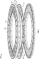
- Figure 2 illustrates an exploded view of one example which is not according to the invention, but which is useful for understanding thereof, showing a partially assembled pneumatic tire 200.
- the pneumatic tire 200 may be assembled using the same composite layer method described above. However, instead of spokes, the method is used to build bead portions (not shown), sidewalls 210, and a tread 220 of the tire. Additionally, the method may be used to build sidewall reinforcement layers (not shown) and crown region reinforcements 230.
- the crown region reinforcements 230 are a pair of rings that define a shear element.
- the crown region may also include reinforcements that define circumferential belts or cap plies, instead of or in addition to the shear element.
- the green tire 200 After the green tire 200 is assembled it is cured in a vulcanization mold or an autoclave.
- electronics may be embedded into layers of the tire.
- an RFID may be embedded in the tire.
- a conductive filament or material could be run through spokes or around other portions of the tire to allow for the detection of damage to the tire. For example, if a spoke is torn there would no longer be a conductive path and this could be sensed by the electronics in the tire.
- Conductive filaments may also be embedded in certain portions of the tire to aid in the discharge of static electricity that may build up as the tire rotates.
- composite layer tires are possible, for both pneumatic and non-pneumatic tires.
- the type of material used as reinforcement may be selected to optimize the weight, stiffness, and other characteristics of the tire under various conditions.
- the amount and location of the reinforcement may also be selected to optimize characteristics of the tire under various conditions.
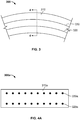
- Figure 3 illustrates a partial side cross-sectional view of one embodiment of a tire 300.
- the tire 300 may be a pneumatic or a non-pneumatic tire.
- the tire 300 may be a composite layer tire, constructed in the manner described above. Alternatively, the tire 300 may be constructed using other tire construction methods.
- the crown region 310 of the tire 300 includes a first pair of reinforcement rings, including a first lower ring 320 and a first upper ring 330.
- the first lower ring 320 is coaxial with the first upper ring 330.
- the first lower ring 320 has a first lower ring diameter
- the first upper ring 330 has a first upper ring diameter.
- Other upper and lower rings on different layers of the crown region may have the same upper and lower diameters, or the diameters may vary. Exemplary cross-sections of selected embodiments of the crown region 310 of tire 300 are illustrated in Figures 4A-4D .
- Figure 4A illustrates a circumferential cross-sectional view of a crown region 310a of one example which is not according to the invention, but which is useful for understanding thereof, showing the tire 300a.
- lower rings 320a and upper rings 330a define a shear element.
- Each lower ring 320a has substantially the same lower ring diameter
- each upper ring 330a has substantially the same upper ring diameter. Therefore, a radial distance between the lower rings 320a and the upper rings 330a is constant along an axial width of the tire.
- Figure 4B illustrates a circumferential cross-sectional view of a crown region 310b of an embodiment of the tire 300b, which is an embodiment of a tire according to the present invention.
- lower rings 320b and upper rings 330b define a shear element.
- the lower ring at the equatorial plane of the tire has the smallest lower ring diameter, and the lower rings at the axial outer ends of the shear element have the greatest lower ring diameters.
- the lower ring diameters from the equatorial plane towards the outer ends of the shear element increase linearly, such that the lower rings form a "V" shape.
- the upper ring at the equatorial plane of the tire has the greatest upper ring diameter
- the upper rings at the axial outer ends of the shear element have the smallest upper ring diameters.
- the upper ring diameters from the equatorial plane towards the outer ends of the shear element decrease linearly, such that the lower rings form an inverted "V" shape.
- the lower rings 320b and the upper rings 330b form a substantially diamond shape. Therefore, a radial distance between the lower rings 320b and the upper rings 330b varies along an axial width of the tire.
- Figure 4C illustrates a circumferential cross-sectional view of a crown region 310c of another alternative embodiment of the tire 300c, which is also an embodiment according to the present invention.
- lower rings 320c and upper rings 330c define a shear element.
- the lower ring at the equatorial plane of the tire has the greatest lower ring diameter, and the lower rings at the axial outer ends of the shear element have the smallest lower ring diameters.
- the lower ring diameters from the equatorial plane towards the outer ends of the shear element decrease linearly, such that the lower rings form an inverted "V" shape.
- the upper ring at the equatorial plane of the tire has the smallest upper ring diameter
- the upper rings at the axial outer ends of the shear element have the greatest upper ring diameters.
- the upper ring diameters from the equatorial plane towards the outer ends of the shear element increase linearly, such that the lower rings form a "V" shape.
- the lower rings 320c and the upper rings 330c form an "X" shape. Therefore, a radial distance between the lower rings 320c and the upper rings 330c varies along an axial width of the tire.
- Figure 4D illustrates a circumferential cross-sectional view of a crown region 310d of an example which is not according to the invention, but which is useful for understanding thereof, showing the tire 300d.
- lower rings 320d and upper rings 330d define a shear element.
- a plurality of lower rings near the equatorial plane of the tire have a first lower ring diameter, and the remaining lower rings have a second lower ring diameter that is smaller than the first lower ring diameter.
- a plurality of upper rings near the equatorial plane of the tire have a first upper ring diameter
- the remaining upper rings have a second upper ring diameter that is greater than the first upper ring diameter.
- the lower rings 320d and the upper rings 330d form a stepped shape. Therefore, a radial distance between the lower rings 320d and the upper rings 330d varies along an axial width of the tire.
- shear elements shown in Figures 4A-4D only represent a small number of possible geometries. In alternative embodiments, any number of geometries may be employed. For example, while the illustrated embodiments show shear elements having linear boundaries, one or more boundaries of a shear element may be curved. Additionally, while the illustrated embodiments show shear elements that are substantially symmetric about an equatorial plane of the tire, in other alternative embodiments, the shear element may be asymmetric. Further, while the illustrated embodiments show shear elements formed by a plurality of lower rings and upper rings, any number of intermediate rings may be disposed between the lower rings and upper rings. Finally, while the shear elements of Figures 4A- 4D are depicted as a plurality of rings, in alternative examples which are not according to the invention, (not shown), the shear elements are formed by a plurality of membranes.
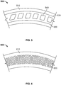
- Figure 5 illustrates a partial side cross-sectional view of one embodiment of a tire 500.
- the tire 500 may be a pneumatic or a non-pneumatic tire.
- the tire 500 may be a composite layer tire, constructed in the manner described above. Alternatively, the tire 500 may be constructed using other tire construction methods.
- the crown region 510 of the tire 500 includes a first pair of reinforcement rings, including a first lower ring 520 and a first upper ring 530. Together, the lower rings and upper rings define a shear element.
- the first lower ring 520 is coaxial with the first upper ring 530.
- the first lower ring 520 has a first lower ring diameter
- the first upper ring 530 has a first upper ring diameter.
- Other upper and lower rings in the crown region may have the same upper and lower diameters, or the diameters may vary.
- the shear element may have any of the cross-sections illustrated in Figures 4A-4D .
- the cross section of the shear element may have any geometric shape.
- any number of intermediate rings may be disposed between the lower rings and upper rings.
- the shear elements are formed by a plurality of membranes.
- a plurality of voids 540 are disposed between the lower rings 520 and the upper rings 530.
- each of the voids 540 has a substantially parallelogram-shaped cross-section. Additionally, each of the voids 540 is substantially the same size.
- the voids may be triangular, pentagonal, hexagonal, octagonal, circular, oval, or have any geometric shape. In other alternative embodiments (not shown), the voids may have a variety of sizes.
- the voids 540 have a consistent cross-section in the axial direction of the tire, and extend across the entire axial width of the shear element.
- the voids may have a variable cross -section.
- the voids only extend across a portion of the axial width of the shear element. In such an embodiment, the voids may be staggered at different axial locations.
- the green rubber When a tire is cured at high temperatures and pressures, the green rubber may flow during the curing process. However, if the tire is cured at lower temperatures or lower pressures, the voids may maintain their shape during the curing process.
- the tire may be cured in an autoclave at a lower pressure than would be provided during a curing process in a tire vulcanization mold. In one embodiment, the tire is cured at a temperature between 38° C to 260° C (100° F to 500° F) and at a pressure between 0.10 mPa to 0.70 mPa (15 PSI to 100 PSI). However, it should be understood that the tire may be cured at other temperatures and pressures.
- Figure 6 illustrates a partial side cross-sectional view of one embodiment of a tire 600.
- the tire 600 may be a pneumatic or a non-pneumatic tire.
- the tire 600 may be a composite layer tire, constructed in the manner described above. Alternatively, the tire 600 may be constructed using other tire construction methods.
- the crown region 610 of the tire 600 includes a reinforcement mesh 620.
- the reinforcement mesh 620 provides additional stiffness in both tension and compression. This may be advantageous in tires that are designed to carry some or all of a load in tension, as well as in tires that are designed to carry some or all of a load in compression. Where the tire 600 is a composite layer tire, the reinforcement mesh 620 may be sandwiched between adjacent layers of polymeric material.
- the reinforcement mesh 620 has a consistent cross-section in the axial direction of the tire.
- the mesh may have a variable cross-section.
- the mesh may have a cross-section corresponding to those illustrated in Figures 4A-4D .
- the cross section of the mesh may have any geometric shape.
- Figure 7 illustrates a partial side cross-sectional view of another embodiment of a tire 700.
- the tire 700 may be a pneumatic or a non-pneumatic tire.
- the tire 700 may be a composite layer tire, constructed in the manner described above. Alternatively, the tire 700 may be constructed using other tire construction methods.
- the crown region 710 of the tire 700 includes a first pair of reinforcement rings, including a first lower ring 720 and a first upper ring 730. Together, the lower rings and upper rings define a shear element.
- the first lower ring 720 is coaxial with the first upper ring 730.
- the first lower ring 720 has a first lower ring diameter
- the first upper ring 730 has a first upper ring diameter.
- Other upper and lower rings in the crown region may have the same upper and lower diameters, or the diameters may vary.
- the shear element may have any of the cross-sections illustrated in Figures 4A-4D .
- the cross section of the shear element may have any geometric shape.
- the shear elements are formed by a plurality of membranes.
- An additional reinforcement 740 is disposed between the first lower ring 720 and the first upper ring 730.
- the additional reinforcement 740 is disposed in a wave formation that oscillates between the first lower ring 720 and the first upper ring 730.
- the additional reinforcement is an annular ring disposed between the first lower ring and the first upper ring. In other alternative embodiments, the additional reinforcement may follow any path.
- an additional reinforcement 740 may be placed on each polymeric sheet of material.
- the additional reinforcement may only be placed on selected sheets.
- the additional reinforcement follows the same path on each sheet.
- the additional reinforcements on different sheets have different paths.
- each additional reinforcement has substantially the same wave shape, but the additional reinforcement on one sheet is rotated with respect to the additional reinforcement on an adjacent sheet.
- Figure 8 illustrates a partial side cross-sectional view of another embodiment of a tire 800.
- the tire 800 is a composite layer tire, constructed in the manner described above.
- the tire 800 may be a pneumatic or a non-pneumatic tire.
- the crown region 810 of the tire 800 includes a pair of reinforcement cords, including a lower cord 820 and an upper cord 830. Together, the lower cords and upper cords define a shear element. Both the lower and upper cords 820, 830 are placed on a polymeric sheet in a substantially circular formation such that the lower cord 820 is coaxial with the upper cord 830.
- a lower hole 840 is formed in the polymeric sheet at a location along the path of the lower cord 820.
- the lower cord 820 may be threaded through lower hole 840 of the polymeric sheet, such that the lower cord 820 is disposed on both sides of the polymeric sheet.
- Adjacent sheets may also have lower holes, so that the lower cord 820 is threaded through multiple sheets of the composite tire 800. In one embodiment, the lower cord 820 is threaded through every polymeric sheet of the composite tire 800.
- the lower hole 840 is pre-formed on the polymeric sheet. In an alternative embodiment, the lower hole is formed during the construction of the composite layer tire 800. In one such embodiment, the lower hole is formed by puncturing the polymeric sheet with the lower cord 820. In an alternative embodiment, the lower hole is formed by a separate tool.
- An upper slit 850 is disposed in the polymeric sheet at a location along the path of the upper cord 830.
- the upper cord 830 may be threaded through upper slit 850 of the polymeric sheet, such that the upper cord 830 is disposed on both sides of the polymeric sheet.
- Adjacent sheets may also have upper slits, so that the upper cord 840 is threaded through multiple sheets of the composite tire 800. In one embodiment, the upper cord 830 is threaded through every polymeric sheet of the composite tire 800.
- the upper slit 850 is pre-formed on the polymeric sheet. In an alternative embodiment, the upper slit is formed during the construction of the composite layer tire 800. In one such embodiment, the upper slit is formed by puncturing the polymeric sheet with the upper cord 830. In an alternative embodiment, the upper slit is formed by a separate tool.
- the polymeric sheet may include an upper and lower hole, or an upper and lower slit.
- the upper and lower cords may be threaded through the polymeric sheets to form a shear element having any geometry.
- the shear element may have any of the cross-sections illustrated in Figures 4A-4D .
- the composite tire 800 of Figure 8 may be further modified to include other features.
- the composite tire may include voids between the upper and lower cords, such as the voids 540 shown in Figure 5 , or the alternative voids discussed above.
- the composite tire may include additional reinforcements between the upper and lower cords, such as the additional reinforcement 740 shown in Figure 7 , or the alternative reinforcements discussed above.
- Figure 9 illustrates a side cross-sectional view of an example which is not according to the invention, but which is useful for understanding thereof, showing a tire 900.
- the tire 900 may be a pneumatic or a non-pneumatic tire.
- the tire 900 may be a composite layer tire, constructed in the manner described above. Alternatively, the tire 900 may be constructed using other tire construction methods.
- the tire 900 includes a spiral reinforcement 910.
- the spiral reinforcement 910 is a single reinforcement that is wrapped around itself.
- the spiral reinforcement is a cord that is placed on a polymeric sheet of material.
- the cord is pre-formed in a spiral configuration.
- the cord is wound about the polymeric sheet as it is being placed. Multiple sheets of polymeric material may have spiral reinforcements.
- the spiral reinforcement defines both the upper and lower layers of a shear element.
- a spiral reinforcement may be wound about a tire made by a traditional tire construction process.
- an inextensible membrane may be coextruded with an elastic material to form a sheet having a single extensible layer and a single inextensible layer. The sheet may be then wrapped around a partially built tire multiple times to form multiple layers of inextensible material.
Landscapes
- Engineering & Computer Science (AREA)
- Mechanical Engineering (AREA)
- Tires In General (AREA)
Description
- The present disclosure is directed to a tire having a shear element and a method of making the same. More particularly, the present disclosure is directed to a tire having a shear element of varying dimensions.
- Various tire constructions have been developed which enable a tire to run in an uninflated or underinflated condition. Non-pneumatic tires do not require inflation, while "run flat tires" may continue to operate after receiving a puncture and a complete or partial loss of pressurized air, for extended periods of time and at relatively high speeds. One such type of run flat tire incorporates a thin annular high strength band element which acts as a tension member when the tire is pressurized and acts as a structural compression member when the tire is in the unpressurized or partially pressurized state. Attention is drawn to the disclosures of
EP1381527 A1 ,US2015/251498 A1 ,US4934429 ,WO94/25297 EP1754615 . - In one embodiment, a method of making a tire includes providing a first substantially circular sheet of polymeric material and placing a first pair of reinforcement rings on the first substantially circular sheet of polymeric material. The first pair of reinforcement rings includes a first lower ring and a first upper ring, wherein the first lower ring is coaxial with the first upper ring. The first lower ring has a first lower ring diameter and the first upper ring has a first upper ring diameter. The method further includes placing a second substantially circular sheet of polymeric material on the first substantially circular sheet of polymeric material such that the first pair of reinforcement rings is sandwiched between the first substantially circular sheet of polymeric material and the second substantially circular sheet of polymeric material. The method also includes placing a second pair of reinforcement rings on the second substantially circular sheet of polymeric material. The second pair of reinforcement rings includes a second lower ring and a second upper ring, wherein the second lower ring is coaxial with the second upper ring. The second lower ring has a second lower ring diameter and the second upper ring has a second upper ring diameter. The method further includes placing a third substantially circular sheet of polymeric material on the second substantially circular sheet of polymeric material such that the second pair of reinforcement rings is sandwiched between the second substantially circular sheet of polymeric material and the third substantially circular sheet of polymeric material. The method also includes placing additional substantially circular sheets of polymeric material and additional pairs of reinforcement rings on the third substantially circular sheet of polymeric material, until a tire is built.
- In another embodiment, a green tire includes a plurality of sheets of green rubber having a substantially circular shape, each sheet having a crown region. The green tire further includes at least one reinforcement sandwiched between adjacent sheets of green rubber in the crown region. The at least one reinforcement defines a substantially inelastic lower region, a substantially inelastic upper region, and an elastic region disposed between the substantially inelastic lower region and the substantially inelastic upper region.
- In yet another embodiment, a tire is provided as claimed in claim 8.
- In the accompanying drawings, structures are illustrated that, together with the detailed description provided below, describe exemplary embodiments of the claimed invention. Like elements are identified with the same reference numerals. It should be understood that elements shown as a single component may be replaced with multiple components, and elements shown as multiple components may be replaced with a single component. The drawings are not to scale and the proportion of certain elements may be exaggerated for the purpose of illustration.
-
Figure 1 illustrates an exploded view of one example which is not according to the invention, but which is useful for understanding thereof, showing a partially assembled non-pneumatic tire; -
Figure 2 illustrates an exploded view of one example which is not according to the invention, but which is useful for understanding thereof, showing a partially assembled pneumatic tire; -
Figure 3 illustrates a partial side cross-sectional view of one embodiment of atire 300; -
Figure 4A-4D illustrate circumferential cross-sectional views of crown regions, in whichFigures 4B and 4C show alternative embodiments of thetire 300 in accordance with the invention; -
Figure 5 illustrates a partial side cross-sectional view of an alternative embodiment of a tire; -
Figure 6 illustrates a partial side cross-sectional view of another alternative embodiment of a tire; -
Figure 7 illustrates a partial side cross-sectional view of yet another alternative embodiment of a tire; -
Figure 8 illustrates a partial side cross-sectional view of still another alternative embodiment of a tire; and -
Figure 9 illustrates a side cross-sectional view of an example which is not according to the invention, but which is useful for understanding thereof, showing a tire. - The following includes definitions of selected terms employed herein. The definitions include various examples and/or forms of components that fall within the scope of a term and that may be used for implementation. The examples are not intended to be limiting. Both singular and plural forms of terms may be within the definitions.
- "3D printer" refers to a machine used for 3D printing.
- "3D printing" refers to the fabrication of objects through the deposition of a material using a print head, nozzle, or another printer technology.
- "Additive manufacturing" refers to a process of joining materials to make objects from 3D model data, usually layer upon layer, as opposed to subtractive manufacturing methodologies. Additive manufacturing includes 3D printing, binder jetting, directed energy deposition, fused deposition modeling, laser sintering, material jetting, material extrusion, powder bed fusion, rapid prototyping, rapid tooling, sheet lamination, and vat photopolymerization.
- "Additive systems" refer to machines used for additive manufacturing.
- "Axial" and "axially" refer to a direction that is parallel to the axis of rotation of a tire.
- "Bead" refers to the part of the tire that contacts a wheel and defines a boundary of the sidewall.
- "Circumferential" and "circumferentially" refer to a direction extending along the perimeter of the surface of the tread perpendicular to the axial direction.
- "Equatorial plane" refers to the plane that is perpendicular to the tire's axis of rotation and passes through the center of the tire's tread.
- "Radial" and "radially" refer to a direction perpendicular to the axis of rotation of a tire.
- "Sidewall" refers to that portion of the tire between the tread and the bead.
- "Spoke" refers to one or more bars, rods, webbing, mesh, or other connecting member extending from a lower member to an upper member. A spoke may include a solid sheet of material.
- "Subtractive manufacturing" refers to making objects by removing of material (for example, buffing, milling, drilling, grinding, carving, cutting, etc.) from a bulk solid to leave a desired shape, as opposed to additive manufacturing.
- "Tread" as used herein, refers to that portion of the tire that comes into contact with the road or ground under normal inflation and normal load.
- "Tread width" refers to the width of the ground contact area of a tread which contacts with road surface during the rotation of the tire under normal inflation and load.
- Directions are stated herein with reference to the axis of rotation of the tire. The terms "upward" and "upwardly" refer to a general direction towards the tread of the tire, whereas "downward" and "downwardly" refer to the general direction towards the axis of rotation of the tire. Thus, when relative directional terms such as "upper" and "lower" or "top" and "bottom" are used in connection with an element, the "upper" or "top" element is spaced closer to the tread than the "lower" or "bottom" element. Additionally, when relative directional terms such as "above" or "below" are used in connection with an element, an element that is "above" another element is closer to the tread than the other element.
- The terms "inward" and "inwardly" refer to a general direction towards the equatorial plane of the tire, whereas "outward" and "outwardly" refer to a general direction away from the equatorial plane of the tire and towards the sidewall of the tire. Thus, when relative directional terms such as "inner" and "outer" are used in connection with an element, the "inner" element is spaced closer to the equatorial plane of the tire than the "outer" element.
- While similar terms used in the following descriptions describe common tire components, it is understood that because the terms carry slightly different connotations, one of ordinary skill in the art would not consider any one of the following terms to be purely interchangeable with another term used to describe a common tire component.
-
Figure 1 illustrates an exploded view of one example which is not according to the invention, but which is useful for understanding thereof, showing a partially assemblednon-pneumatic tire 100. Thenon-pneumatic tire 100 includes a plurality of sheets ofpolymeric material 110 having a substantially circular shape. In this particular example, each sheet of polymeric material includes anupper ring 120, alower ring 130, and a plurality ofspoke portions 140 extending from theupper ring 120 to thelower ring 130. In an alternative example (not shown), not every sheet of polymeric material includes an upper ring, a lower ring, and a plurality of spoke portions. In one such example, some sheets include an upper ring, a lower ring, and a plurality of spoke portions, while other sheets omit the spoke portion or the lower ring. In another example, some sheets omit the upper ring. - In the illustrated example, the
upper ring 120 of each sheet includes a tread portion. The tread portion is shaped to form a tread design. In the illustrated example, the tread portion forms a tread design having a plurality of rectangular tread blocks separated by a plurality of lateral grooves. In alternative embodiments (not shown), the tread portion may form a tread design having ribs, circumferential grooves, sipes, or tread blocks of various shapes and sizes. The tread may be symmetric or asymmetric. - In the illustrated example, each sheet of polymeric material includes 24 spoke portions. In alternative examples, each sheet of polymeric material may have any number of spoke portions. In some examples, each sheet of polymeric material has 10-40 spoke portions.
- In the illustrated example, each sheet of
polymeric material 110 has the same number ofspoke portions 140. Additionally, each spokeportion 140 in eachsheet 110 has substantially the same shape and size. Further, thespoke portions 140 ofadjacent sheets 110 are aligned with each other. However, it should be understood that in alternative examples, some sheets may have a different number of spoke portions. Additionally, in other alternative embodiments, the sizes and shapes of the spoke portions on a given sheet may vary. Likewise, in still other alternative examples, the spoke portions on a given sheet may have different sizes and shape with respect to the spoke portions on another sheet. Moreover, the spoke portions of different sheets may not be aligned with each other. - In one embodiment, each sheet of polymeric material is constructed of green rubber. In an alternative embodiment, each sheet of polymeric material is constructed of cured rubber. In alternative embodiments, the sheet of polymeric material may be constructed of a foamed polymer, polyurethane, thermoplastics, resins, other elastomeric or polymeric material, other syntheticor natural fibers, and other metal materials. In another alternative embodiment, the sheet is formed of metal instead of a polymeric material. In one embodiment, each sheet is made of a uniform material. In an alternative embodiment, each sheet is constructed of a plurality of different materials. For example, the tread portion, upper ring, lower ring, and spokes may be constructed of different materials. Additionally, different sheets may be constructed of different materials. In any of the above embodiments, adhesive may be employed between sheets of material.
- In one embodiment, each sheet of polymeric material is formed by an additive manufacturing method. For example, each sheet may be made by 3D printing, binder jetting, directed energy deposition, fused deposition modeling, laser sintering, material jetting, material extrusion, powder bed fusion, rapid prototyping, rapid tooling, sheet lamination, or vat photopolymerization. A jig or other fixture may be employed to aid in the assembly of multiple sheets to ensure proper orientation of each sheet. Alternatively, a jig or fixture may help define the shape of an individual sheet during the additive manufacturing process.
- In an alternative embodiment, each sheet of polymeric material is formed by a subtractive manufacturing method. For example, the sheet of polymeric material may be cut (such as with a die, knife, or laser). Where a subtractive process is used, the sheet may be shaped before it is placed on top of the other sheets. Alternatively, the sheet may be only partially formed before it is placed on top of the other sheets, and then cut to its final shape after placement. Such a process would obviate the need for exactly placement of the sheet.
- In another alternative embodiment, each sheet of polymeric material is formed by a molding process.
- In one embodiment, each sheet of
polymeric material 110 has a thickness of about 2 mm (∼0.080 inches). In alternative embodiments, each sheet of polymeric material may have a thickness between 0.02 mm to 25.4 mm (0.001 inches to 1 inch). In one embodiment, each sheet of polymeric material in the tire has substantially the same thickness. In alternative embodiments, the thickness of the sheets may vary. For example, thicker or thinner sheets may be used at different locations to change the spacing or placement of a reinforcement. It should be understood that in an additive manufacturing process, the sheets may not be visibly distinct from each other and thus they may not have a discernible thickness. - With continued reference to
Figure 1 , thenon-pneumatic tire 100 further includes a plurality ofreinforcements 150, with eachreinforcement 150 being disposed between adjacent sheets ofpolymeric material 110. In the illustrated embodiment, thereinforcement 150 is a plurality of cords forming a pair ofupper rings 160, alower ring 170, and a plurality ofspoke reinforcements 180. The cords may also be referred to as wires or filaments. Theupper rings 160 of thereinforcement 150 are sandwiched between theupper rings 120 of adjacent sheets ofpolymeric material 110. Likewise, thelower ring 170 of thereinforcement 150 is sandwiched between thelower rings 130 of adjacent sheets ofpolymeric material 110. Additionally, thespoke reinforcements 180 are sandwiched between thespoke portions 140 of adjacent sheets ofpolymeric material 110. - The pair of
upper rings 160 of thereinforcement 150 are positioned such that when thetire 100 is cured, theupper rings 160 of thereinforcement 150 form a shear element defined by the upper pair ofrings 120 of the sheets ofpolymeric material 110. In other words, a portion of theupper rings 120 of thepolymeric material 110 is an elastic material disposed radially between the substantially inelastic membranes formed by the pair ofupper rings 160 of thereinforcement 150. - However, it should be understood that the shape of the
reinforcement 150 shown inFigure 1 is merely exemplary. In alternative embodiments, some or all of theupper rings 160 of thereinforcement 150 may be omitted. Likewise, some or all of thelower rings 170 of thereinforcement 150 may be omitted. Additionally, some or all of thespoke reinforcements 180 may be omitted. In other alternative embodiments, multiple reinforcements may be employed on some portions. While the reinforcements are continuous components in the illustrated embodiment, it should be understood that the reinforcements may be discontinuous. For example, the reinforcements may be chopped fibers that are distributed along portions of a polymeric sheet. - The
reinforcement 150 may be constructed of a material selected from the group consisting of steel, polyester, nylon, carbon fiber, aramid, fiber glass, cotton, hemp, polyurethane and other plastic, other synthetic or natural fibers, and other metal materials. While thereinforcement 150 is shown as a plurality of cords inFigure 1 , in alternative embodiments, the reinforcement is a mesh of material or a sheet of material. In another alternative embodiment, the reinforcement may be chopped fibers. - To construct the
non-pneumatic tire 100, the method includes forming a first sheet ofpolymeric material 110 having a substantially circular shape. The first sheet ofpolymeric material 110 may be formed using any of the methods described above. The first sheet ofpolymeric material 110 may be formed on a flat surface, or it may be formed on a jig or fixture. - The method then includes placing a
reinforcement 150 on the first sheet ofpolymeric material 110. In one embodiment, thereinforcement 150 has a preformed shape before it is placed on the first sheet ofpolymeric material 110. In an alternative embodiment, thereinforcement 150 may be shaped as it is being placed on the first sheet ofpolymeric material 110. For example, the reinforcement may be extruded or 3D printed onto the first sheet ofpolymeric material 110. - The method further includes placing a second sheet of polymeric material having a substantially circular shape on the first sheet of polymeric material, such that the
reinforcement 150 is sandwiched between the first sheet of polymeric material and the second sheet of polymeric material. The method is then repeated, so that additional reinforcements and additional sheets of polymeric material are placed on top of each other until a tire is built having a predetermined width. In other words, the tire is built in a direction perpendicular to the axis of rotation of the tire, and the number of layers and their width determines the width of the tire. In one embodiment, the tire has a width of 190 mm (7.5 inches). In other embodiments, the tire has a width of 12.5 mm to 1525 mm (0.5 inches to 60 inches). A tire having a plurality of layers in the axial direction may be referred to as a composite layer tire. - In one embodiment, adhesive or cement may be applied to a sheet of polymeric material before or after the reinforcement is placed on it. Additionally, additives or chemical treatment may be selectively applied to the polymeric sheets or to the reinforcements during the build process. Further, some sheets of polymeric material may have a contoured surface or a roughened surface to promote adhesion. For example, a sheet of polymeric material may go through a roughening process after it is placed on the tire.
- While
Figure 1 shows alternating layers of polymeric sheets and reinforcements, it should be understood that several layers of polymeric sheets may be placed together or several layers of reinforcements may be placed together. It should also be understood that the reinforcements may vary on different layers. For example, a lower ring reinforcement may be placed on a first sheet, a pair of upper ring reinforcements may be placed on a second sheet, and spoke reinforcements may be placed on a third sheet. - After the
tire 110 is built, it is then cured. In one embodiment, the tire is cured in a vulcanization mold. When the tire is cured in a vulcanization mold, the outer surfaces of the tire may be further shaped during vulcanization. In an alternative embodiment, the tire is cured in an autoclave. An autoclave may cure the tire at lower pressures than a typical vulcanization mold, thereby allowing the tire to maintain its shape. In yet another embodiment, the tire may be cured between metal plates of other materials. In still another embodiment, the curing step may be omitted. -
Figure 2 illustrates an exploded view of one example which is not according to the invention, but which is useful for understanding thereof, showing a partially assembled pneumatic tire 200. The pneumatic tire 200 may be assembled using the same composite layer method described above. However, instead of spokes, the method is used to build bead portions (not shown),sidewalls 210, and atread 220 of the tire. Additionally, the method may be used to build sidewall reinforcement layers (not shown) andcrown region reinforcements 230. In the illustrated embodiment, thecrown region reinforcements 230 are a pair of rings that define a shear element. The crown region may also include reinforcements that define circumferential belts or cap plies, instead of or in addition to the shear element. - After the green tire 200 is assembled it is cured in a vulcanization mold or an autoclave.
- In both the pneumatic and non-pneumatic examples, electronics may be embedded into layers of the tire. For example, an RFID may be embedded in the tire. A conductive filament or material could be run through spokes or around other portions of the tire to allow for the detection of damage to the tire. For example, if a spoke is torn there would no longer be a conductive path and this could be sensed by the electronics in the tire. Conductive filaments may also be embedded in certain portions of the tire to aid in the discharge of static electricity that may build up as the tire rotates.
- Many variations of composite layer tires are possible, for both pneumatic and non-pneumatic tires. For example, the type of material used as reinforcement may be selected to optimize the weight, stiffness, and other characteristics of the tire under various conditions. Likewise, the amount and location of the reinforcement may also be selected to optimize characteristics of the tire under various conditions.
-
Figure 3 illustrates a partial side cross-sectional view of one embodiment of atire 300. In this illustration, only acrown region 310 of the tire is shown. Thetire 300 may be a pneumatic or a non-pneumatic tire. Thetire 300 may be a composite layer tire, constructed in the manner described above. Alternatively, thetire 300 may be constructed using other tire construction methods. - In the illustrated cross-section, the
crown region 310 of thetire 300 includes a first pair of reinforcement rings, including a firstlower ring 320 and a firstupper ring 330. The firstlower ring 320 is coaxial with the firstupper ring 330. The firstlower ring 320 has a first lower ring diameter, and the firstupper ring 330 has a first upper ring diameter. Other upper and lower rings on different layers of the crown region may have the same upper and lower diameters, or the diameters may vary. Exemplary cross-sections of selected embodiments of thecrown region 310 oftire 300 are illustrated inFigures 4A-4D . -
Figure 4A illustrates a circumferential cross-sectional view of acrown region 310a of one example which is not according to the invention, but which is useful for understanding thereof, showing thetire 300a. In the illustrated example,lower rings 320a andupper rings 330a define a shear element. Eachlower ring 320a has substantially the same lower ring diameter, and eachupper ring 330a has substantially the same upper ring diameter. Therefore, a radial distance between thelower rings 320a and theupper rings 330a is constant along an axial width of the tire. -
Figure 4B illustrates a circumferential cross-sectional view of acrown region 310b of an embodiment of thetire 300b, which is an embodiment of a tire according to the present invention. . In the illustrated embodiment,lower rings 320b andupper rings 330b define a shear element. The lower ring at the equatorial plane of the tire has the smallest lower ring diameter, and the lower rings at the axial outer ends of the shear element have the greatest lower ring diameters. The lower ring diameters from the equatorial plane towards the outer ends of the shear element increase linearly, such that the lower rings form a "V" shape. - By contrast, the upper ring at the equatorial plane of the tire has the greatest upper ring diameter, and the upper rings at the axial outer ends of the shear element have the smallest upper ring diameters. The upper ring diameters from the equatorial plane towards the outer ends of the shear element decrease linearly, such that the lower rings form an inverted "V" shape. Together, the
lower rings 320b and theupper rings 330b form a substantially diamond shape. Therefore, a radial distance between thelower rings 320b and theupper rings 330b varies along an axial width of the tire. -
Figure 4C illustrates a circumferential cross-sectional view of acrown region 310c of another alternative embodiment of thetire 300c, which is also an embodiment according to the present invention. In the illustrated embodiment,lower rings 320c andupper rings 330c define a shear element. The lower ring at the equatorial plane of the tire has the greatest lower ring diameter, and the lower rings at the axial outer ends of the shear element have the smallest lower ring diameters. The lower ring diameters from the equatorial plane towards the outer ends of the shear element decrease linearly, such that the lower rings form an inverted "V" shape. - By contrast, the upper ring at the equatorial plane of the tire has the smallest upper ring diameter, and the upper rings at the axial outer ends of the shear element have the greatest upper ring diameters. The upper ring diameters from the equatorial plane towards the outer ends of the shear element increase linearly, such that the lower rings form a "V" shape. Together, the
lower rings 320c and theupper rings 330c form an "X" shape. Therefore, a radial distance between thelower rings 320c and theupper rings 330c varies along an axial width of the tire. -
Figure 4D illustrates a circumferential cross-sectional view of acrown region 310d of an example which is not according to the invention, but which is useful for understanding thereof, showing thetire 300d. In the illustrated embodiment,lower rings 320d andupper rings 330d define a shear element. A plurality of lower rings near the equatorial plane of the tire have a first lower ring diameter, and the remaining lower rings have a second lower ring diameter that is smaller than the first lower ring diameter. - By contrast, a plurality of upper rings near the equatorial plane of the tire have a first upper ring diameter, and the remaining upper rings have a second upper ring diameter that is greater than the first upper ring diameter. Together, the
lower rings 320d and theupper rings 330d form a stepped shape. Therefore, a radial distance between thelower rings 320d and theupper rings 330d varies along an axial width of the tire. - It should be understood that the exemplary embodiments of shear elements shown in
Figures 4A-4D only represent a small number of possible geometries. In alternative embodiments, any number of geometries may be employed. For example, while the illustrated embodiments show shear elements having linear boundaries, one or more boundaries of a shear element may be curved. Additionally, while the illustrated embodiments show shear elements that are substantially symmetric about an equatorial plane of the tire, in other alternative embodiments, the shear element may be asymmetric. Further, while the illustrated embodiments show shear elements formed by a plurality of lower rings and upper rings, any number of intermediate rings may be disposed between the lower rings and upper rings. Finally, while the shear elements ofFigures 4A- 4D are depicted as a plurality of rings, in alternative examples which are not according to the invention, (not shown), the shear elements are formed by a plurality of membranes. -
Figure 5 illustrates a partial side cross-sectional view of one embodiment of atire 500. In this illustration, only acrown region 510 of the tire is shown. Thetire 500 may be a pneumatic or a non-pneumatic tire. Thetire 500 may be a composite layer tire, constructed in the manner described above. Alternatively, thetire 500 may be constructed using other tire construction methods. - In the illustrated cross-section, the
crown region 510 of thetire 500 includes a first pair of reinforcement rings, including a firstlower ring 520 and a firstupper ring 530. Together, the lower rings and upper rings define a shear element. The firstlower ring 520 is coaxial with the firstupper ring 530. The firstlower ring 520 has a first lower ring diameter, and the firstupper ring 530 has a first upper ring diameter. Other upper and lower rings in the crown region may have the same upper and lower diameters, or the diameters may vary. For example, the shear element may have any of the cross-sections illustrated inFigures 4A-4D . Alternatively, the cross section of the shear element may have any geometric shape. In other alternative embodiments (not shown), any number of intermediate rings may be disposed between the lower rings and upper rings. In still other alternative embodiments (not shown), the shear elements are formed by a plurality of membranes. - A plurality of
voids 540 are disposed between thelower rings 520 and the upper rings 530. In the illustrated embodiment, each of thevoids 540 has a substantially parallelogram-shaped cross-section. Additionally, each of thevoids 540 is substantially the same size. In alternative embodiments (not shown), the voids may be triangular, pentagonal, hexagonal, octagonal, circular, oval, or have any geometric shape. In other alternative embodiments (not shown), the voids may have a variety of sizes. - In one embodiment, the
voids 540 have a consistent cross-section in the axial direction of the tire, and extend across the entire axial width of the shear element. In an alternative embodiment, the voids may have a variable cross -section. In another alternative embodiment, the voids only extend across a portion of the axial width of the shear element. In such an embodiment, the voids may be staggered at different axial locations. - When a tire is cured at high temperatures and pressures, the green rubber may flow during the curing process. However, if the tire is cured at lower temperatures or lower pressures, the voids may maintain their shape during the curing process. For example, the tire may be cured in an autoclave at a lower pressure than would be provided during a curing process in a tire vulcanization mold. In one embodiment, the tire is cured at a temperature between 38° C to 260° C (100° F to 500° F) and at a pressure between 0.10 mPa to 0.70 mPa (15 PSI to 100 PSI). However, it should be understood that the tire may be cured at other temperatures and pressures.
-
Figure 6 illustrates a partial side cross-sectional view of one embodiment of atire 600. In this illustration, only acrown region 610 of the tire is shown. Thetire 600 may be a pneumatic or a non-pneumatic tire. Thetire 600 may be a composite layer tire, constructed in the manner described above. Alternatively, thetire 600 may be constructed using other tire construction methods. - In the illustrated cross-section, the
crown region 610 of thetire 600 includes areinforcement mesh 620. Thereinforcement mesh 620 provides additional stiffness in both tension and compression. This may be advantageous in tires that are designed to carry some or all of a load in tension, as well as in tires that are designed to carry some or all of a load in compression. Where thetire 600 is a composite layer tire, thereinforcement mesh 620 may be sandwiched between adjacent layers of polymeric material. - In one embodiment, the
reinforcement mesh 620 has a consistent cross-section in the axial direction of the tire. In an alternative embodiment, the mesh may have a variable cross-section. For example, the mesh may have a cross-section corresponding to those illustrated inFigures 4A-4D . Alternatively, although not according to the invention the cross section of the mesh may have any geometric shape. -
Figure 7 illustrates a partial side cross-sectional view of another embodiment of atire 700. In this illustration, only acrown region 710 of the tire is shown. Thetire 700 may be a pneumatic or a non-pneumatic tire. Thetire 700 may be a composite layer tire, constructed in the manner described above. Alternatively, thetire 700 may be constructed using other tire construction methods. - In the illustrated cross-section, the
crown region 710 of thetire 700 includes a first pair of reinforcement rings, including a firstlower ring 720 and a firstupper ring 730. Together, the lower rings and upper rings define a shear element. The firstlower ring 720 is coaxial with the firstupper ring 730. The firstlower ring 720 has a first lower ring diameter, and the firstupper ring 730 has a first upper ring diameter. Other upper and lower rings in the crown region may have the same upper and lower diameters, or the diameters may vary. For example, the shear element may have any of the cross-sections illustrated inFigures 4A-4D . Alternatively, the cross section of the shear element may have any geometric shape. In still other alternative examples not according to the invention (not shown), the shear elements are formed by a plurality of membranes. - An
additional reinforcement 740 is disposed between the firstlower ring 720 and the firstupper ring 730. In the illustrated embodiment, theadditional reinforcement 740 is disposed in a wave formation that oscillates between the firstlower ring 720 and the firstupper ring 730. In an alternative embodiment (not shown), the additional reinforcement is an annular ring disposed between the first lower ring and the first upper ring. In other alternative embodiments, the additional reinforcement may follow any path. - In the case of a composite layer tire, an
additional reinforcement 740 may be placed on each polymeric sheet of material. Alternatively, the additional reinforcement may only be placed on selected sheets. In one embodiment, the additional reinforcement follows the same path on each sheet. In an alternative embodiment, the additional reinforcements on different sheets have different paths. For example, in one known embodiment, each additional reinforcement has substantially the same wave shape, but the additional reinforcement on one sheet is rotated with respect to the additional reinforcement on an adjacent sheet. -
Figure 8 illustrates a partial side cross-sectional view of another embodiment of atire 800. In this illustration, only acrown region 810 of the tire is shown. Thetire 800 is a composite layer tire, constructed in the manner described above. Thetire 800 may be a pneumatic or a non-pneumatic tire. - In the illustrated cross-section, the
crown region 810 of thetire 800 includes a pair of reinforcement cords, including alower cord 820 and anupper cord 830. Together, the lower cords and upper cords define a shear element. Both the lower andupper cords lower cord 820 is coaxial with theupper cord 830. - A
lower hole 840 is formed in the polymeric sheet at a location along the path of thelower cord 820. Thelower cord 820 may be threaded throughlower hole 840 of the polymeric sheet, such that thelower cord 820 is disposed on both sides of the polymeric sheet. Adjacent sheets (not shown) may also have lower holes, so that thelower cord 820 is threaded through multiple sheets of thecomposite tire 800. In one embodiment, thelower cord 820 is threaded through every polymeric sheet of thecomposite tire 800. - In one embodiment, the
lower hole 840 is pre-formed on the polymeric sheet. In an alternative embodiment, the lower hole is formed during the construction of thecomposite layer tire 800. In one such embodiment, the lower hole is formed by puncturing the polymeric sheet with thelower cord 820. In an alternative embodiment, the lower hole is formed by a separate tool. - An
upper slit 850 is disposed in the polymeric sheet at a location along the path of theupper cord 830. Theupper cord 830 may be threaded throughupper slit 850 of the polymeric sheet, such that theupper cord 830 is disposed on both sides of the polymeric sheet. Adjacent sheets (not shown) may also have upper slits, so that theupper cord 840 is threaded through multiple sheets of thecomposite tire 800. In one embodiment, theupper cord 830 is threaded through every polymeric sheet of thecomposite tire 800. - In one embodiment, the
upper slit 850 is pre-formed on the polymeric sheet. In an alternative embodiment, the upper slit is formed during the construction of thecomposite layer tire 800. In one such embodiment, the upper slit is formed by puncturing the polymeric sheet with theupper cord 830. In an alternative embodiment, the upper slit is formed by a separate tool. - While the illustrated embodiment shows a
lower hole 840 and anupper slit 850, it should be understood that any type of opening may be formed in either location. For example, the polymeric sheet may include an upper and lower hole, or an upper and lower slit. - The upper and lower cords may be threaded through the polymeric sheets to form a shear element having any geometry. For example, the shear element may have any of the cross-sections illustrated in
Figures 4A-4D . - The
composite tire 800 ofFigure 8 may be further modified to include other features. For example, the composite tire may include voids between the upper and lower cords, such as thevoids 540 shown inFigure 5 , or the alternative voids discussed above. Additionally, the composite tire may include additional reinforcements between the upper and lower cords, such as theadditional reinforcement 740 shown inFigure 7 , or the alternative reinforcements discussed above. -
Figure 9 illustrates a side cross-sectional view of an example which is not according to the invention, but which is useful for understanding thereof, showing atire 900. Thetire 900 may be a pneumatic or a non-pneumatic tire. Thetire 900 may be a composite layer tire, constructed in the manner described above. Alternatively, thetire 900 may be constructed using other tire construction methods. - The
tire 900 includes aspiral reinforcement 910. Thespiral reinforcement 910 is a single reinforcement that is wrapped around itself. For example, in a composite layer construction, the spiral reinforcement is a cord that is placed on a polymeric sheet of material. In one embodiment, the cord is pre-formed in a spiral configuration. In an alternative embodiment, the cord is wound about the polymeric sheet as it is being placed. Multiple sheets of polymeric material may have spiral reinforcements. When the tire is cured, the spiral reinforcement defines both the upper and lower layers of a shear element. - In an alternative example, a spiral reinforcement may be wound about a tire made by a traditional tire construction process. For example, an inextensible membrane may be coextruded with an elastic material to form a sheet having a single extensible layer and a single inextensible layer. The sheet may be then wrapped around a partially built tire multiple times to form multiple layers of inextensible material.
- While the present disclosure has been illustrated by the description of embodiments thereof, and while the embodiments have been described in considerable detail, it is not the intention of the applicants to restrict or in any way limit the scope of the appended claims to such detail. Additional advantages and modifications will readily appear to those skilled in the art. Therefore, the disclosure, in its broader aspects, is not limited to the specific details, the representative apparatus and method, and illustrative examples shown and described. Accordingly, departures may be made from such details without departing from the scope of the applicant's general inventive concept as defined by the appended claims.
- To the extent that the term "includes" or "including" is used in the specification or the claims, it is intended to be inclusive in a manner similar to the term "comprising" as that term is interpreted when employed as a transitional word in a claim. Furthermore, to the extent that the term "or" is employed (e.g., A or B) it is intended to mean "A or B or both." When the applicants intend to indicate "only A or B but not both" then the term "only A or B but not both" will be employed. Thus, use of the term "or" herein is the inclusive, and not the exclusive use. See, Bryan A. Garner, A Dictionary of Modern Legal Usage 624 (2d. Ed. 1995). Also, to the extent that the terms "in" or "into" are used in the specification or the claims, it is intended to additionally mean "on" or "onto." Furthermore, to the extent the term "connect" is used in the specification or claims, it is intended to mean not only "directly connected to," but also "indirectly connected to" such as connected through another component or components.
Claims (13)
- A method of making a tire (100; 200; 300; 500; 700; 800; 900) comprising:providing a first substantially circular sheet of polymeric material (110);placing a first pair of reinforcement rings (160; 320, 330; 520, 530; 720, 730; 820, 830; 910) on the first substantially circular sheet of polymeric material (110), wherein the first pair of reinforcement rings includes a first lower ring (320; 520; 720; 820; 910) and a first upper ring (330; 530; 730; 830; 910),wherein the first lower ring (320; 520; 720; 820; 910) is coaxial with the first upper ring (330; 530; 730; 830; 910),wherein the first lower ring (320; 520; 720; 820; 910) has a first lower ring diameter, andwherein the first upper ring (330; 530; 730; 830; 910) has a first upper ring diameter;placing a second substantially circular sheet of polymeric material (110) on the first substantially circular sheet of polymeric material (110) such that the first pair of reinforcement rings (160; 320, 330; 520, 530; 720, 730; 820, 830; 910) is sandwiched between the first substantially circular sheet of polymeric material (110) and the second substantially circular sheet of polymeric material (110);placing a second pair of reinforcement rings (160; 320, 330; 520, 530; 720, 730; 820, 830; 910) on the second substantially circular sheet of polymeric material (110), wherein the second pair of reinforcement rings includes a second lower ring (320; 520; 720; 820; 910) and a second upper ring (330; 530; 730; 830; 910),wherein the second lower ring (320; 520; 720; 820; 910) is coaxial with the second upper ring (330; 530; 730; 830; 910),wherein the second lower ring (320; 520; 720; 820; 910) has a second lower ring diameter, andwherein the second upper ring (330; 530; 730; 830; 910) has a second upper ring diameter;placing a third substantially circular sheet of polymeric material (110) on the second substantially circular sheet of polymeric material (110) such that the second pair of reinforcement rings (160; 320, 330; 520, 530; 720, 730) is sandwiched between the second substantially circular sheet of polymeric material (110) and the third substantially circular sheet of polymeric material (110);placing additional substantially circular sheets of polymeric material (110) and additional pairs of reinforcement rings (160; 320, 330; 520, 530; 720, 730; 820, 830; 910) on the third substantially circular sheet of polymeric material (110), until a tire (100; 200; 300; 500; 700; 800; 900) is built.
- The method of claim 1, further comprising curing the tire (100; 200; 300; 500; 700; 800; 900).
- The method of claim 1, wherein the first lower ring diameter is different from the second lower ring diameter.
- The method of claim 1, wherein the first upper ring diameter is different from the second upper ring diameter.
- The method of claim 1, further comprising:placing a first additional reinforcement (740) between the first pair of reinforcement rings (160; 320, 330; 520, 530; 720, 730; 820, 830; 910); andplacing a second additional reinforcement (740) between the second pair of reinforcement rings (160; 320, 330; 520, 530; 720, 730; 820, 830; 910).
- The method of claim 5, wherein the first additional reinforcement (740) is placed in a wave formation that oscillates between the first lower ring (320; 520; 720; 820; 910) and the first upper ring (330; 530; 730; 830; 910), and wherein the second additional reinforcement (740) is placed in a wave formation that oscillates between the second lower ring (320; 520; 720; 820; 910) and the second upper ring (330; 530; 730; 830; 910).
- The method of claim 1, further comprising forming a plurality of voids (540) in the first substantially circular sheet of polymeric material (110) in a region between the first lower ring (320; 520; 720; 820; 910) and the first upper ring (330; 530; 730; 830; 910).
- A tire (300;) comprising:a central region configured to be mounted to a wheel;a crown region (310) including a circumferential tread and a shear element disposed below the circumferential tread; andan intermediate region extending from the central region to the crown region (310),wherein the shear element includes an upper reinforcement layer (330), a lower reinforcement layer (320), and an elastic region disposed between the upper reinforcement layer (330) and the lower reinforcement layer (320), andcharacterized in thatthe upper reinforcement layer (330) includes a plurality of upper rings (330b, 330c) and the lower reinforcement layer (320) includes a plurality of lower rings (320b. 320c), wherein said upper rings (330b. 330c) are spaced from each other in the axial direction of the tire and wherein said lower rings (330b, 330c) are spaced from each other in the axial direction of the tire,and in that both the upper ring diameters and the lower ring diameters vary linearly along the axial width of the tire, such that a radial distance between the upper rings (330b, 330c) and the lower rings (320b, 320c) varies along the axial width of the tire (300).
- The tire (100; 200; 300; 500; 700; 800; 900) of claim 8, wherein the radial distance between the upper reinforcement layer (330; 530; 730; 830; 910) and the lower reinforcement layer (320; 520; 720; 820; 910) is greatest at an equatorial plane of the tire (100; 200; 300; 500; 700; 800; 900).
- The tire (100; 200; 300; 500; 700; 800; 900) of claim 8, wherein the radial distance between the upper reinforcement layer (330; 530; 730; 830; 910) and the lower reinforcement layer (320; 520; 720; 820; 910) at axial outer ends of the tire (100; 200; 300; 500; 700; 800; 900) is greater than the radial distance between the upper reinforcement layer and the lower reinforcement layer at an equatorial plane of the tire (100; 200; 300; 500; 700; 800; 900).
- The tire (100; 200; 300; 500; 700; 800; 900) of claim 8, wherein the tire is a pneumatic tire.
- The tire (100; 200; 300; 500; 700; 800; 900) of claim 8, wherein the tire is a non-pneumatic tire.
- The tire (100; 200; 300; 500; 700; 800; 900) of claim 8, wherein the tire has a plurality of layers in the axial direction.
Applications Claiming Priority (2)
| Application Number | Priority Date | Filing Date | Title |
|---|---|---|---|
| US201562272153P | 2015-12-29 | 2015-12-29 | |
| PCT/US2016/067668 WO2017116823A1 (en) | 2015-12-29 | 2016-12-20 | Tire with variable shear element |
Publications (3)
| Publication Number | Publication Date |
|---|---|
| EP3397467A1 EP3397467A1 (en) | 2018-11-07 |
| EP3397467A4 EP3397467A4 (en) | 2019-07-03 |
| EP3397467B1 true EP3397467B1 (en) | 2021-04-14 |
Family
ID=59225362
Family Applications (1)
| Application Number | Title | Priority Date | Filing Date |
|---|---|---|---|
| EP16882362.3A Active EP3397467B1 (en) | 2015-12-29 | 2016-12-20 | Tire with variable shear element |
Country Status (4)
| Country | Link |
|---|---|
| US (2) | US11186053B2 (en) |
| EP (1) | EP3397467B1 (en) |
| CN (1) | CN108698345B (en) |
| WO (1) | WO2017116823A1 (en) |
Families Citing this family (9)
| Publication number | Priority date | Publication date | Assignee | Title |
|---|---|---|---|---|
| US11318790B2 (en) * | 2016-04-13 | 2022-05-03 | The Goodyear Tire & Robber Company | Shear band and non-pneumatic tire |
| EP3339055B1 (en) * | 2016-12-21 | 2020-03-04 | Bridgestone Americas Tire Operations, LLC | Tire with tensioned spokes |
| US10749242B2 (en) | 2017-10-30 | 2020-08-18 | The Goodyear Tire & Rubber Company | Non-pneumatic tire with radio frequency identification |
| JP6959895B2 (en) * | 2018-06-19 | 2021-11-05 | 株式会社ブリヂストン | Manufacturing method for pneumatic tires and resin-coated belts |
| WO2020139682A1 (en) * | 2018-12-28 | 2020-07-02 | Bridgestone Americas Tire Operations, Llc | Metal web for a non-pneumatic tire and method of making same |
| DE102019116163A1 (en) * | 2019-06-13 | 2020-12-17 | Texmag Gmbh Vertriebsgesellschaft | Method and device for producing a material strip with an integrated electronic component |
| EP4017741B1 (en) * | 2019-08-22 | 2025-10-01 | FineLine Technologies | Chemically treated, rfid equipped mesh tire labels and methods of making and using the same for identification and tracking purposes during and post-tire manufacture |
| US12304244B2 (en) | 2019-12-30 | 2025-05-20 | Bridgestone Americas Tire Operations, Llc | Non-pneumatic tire having molded sidewall cover |
| CN117048251B (en) * | 2023-06-28 | 2025-12-12 | 青岛海润博橡胶制品有限公司 | A sidewall reinforcement structure for aircraft tires, manufacturing equipment and manufacturing method |
Citations (2)
| Publication number | Priority date | Publication date | Assignee | Title |
|---|---|---|---|---|
| WO1994025297A1 (en) * | 1993-04-26 | 1994-11-10 | PERBÍRÓ, Sándor | Vehicle tyre |
| EP1754615A1 (en) * | 2005-08-19 | 2007-02-21 | Continental Aktiengesellschaft | Vehicle tire |
Family Cites Families (46)
| Publication number | Priority date | Publication date | Assignee | Title |
|---|---|---|---|---|
| US1911524A (en) * | 1933-05-30 | nalinne | ||
| GB169320A (en) * | 1920-07-08 | 1921-09-29 | Emile Carpentier | An improved elastic tyre |
| US1447784A (en) | 1922-08-31 | 1923-03-06 | Kelly Springfield Tire Company | Resilient tire |
| US2245444A (en) * | 1939-04-22 | 1941-06-10 | Frederick N Ross | Wheel structure |
| US2264767A (en) | 1939-08-23 | 1941-12-02 | Goodrich Co B F | Tire tread |
| DE915782C (en) * | 1940-12-04 | 1954-07-29 | Tech Fortschritt M B H Ges | Solid rubber tires for vehicle wheels |
| US4287927A (en) * | 1978-06-30 | 1981-09-08 | The Goodyear Tire & Rubber Company | Multiple ring tire |
| US4934429A (en) * | 1987-11-06 | 1990-06-19 | Bridgestone Corporation | Low-section pneumatic radial tires |
| JPH0733023B2 (en) | 1991-11-29 | 1995-04-12 | 住友ゴム工業株式会社 | Master model for tire mold |
| US5460213A (en) | 1992-03-18 | 1995-10-24 | Uniroyal Goodrich Licensing Services, Inc. | Multiple non-pneumatic tire and process for making it |
| FR2787388B1 (en) | 1998-12-18 | 2001-01-12 | Conception & Dev Michelin Sa | ELASTIC BANDAGE THAT CAN BE USED NON-PNEUMATICALLY |
| US6279630B1 (en) * | 1998-12-23 | 2001-08-28 | Daimlerchrysler Ag | Non pneumatic tires |
| US7418988B2 (en) * | 1999-12-10 | 2008-09-02 | Michelin Recherche Et Technique S.A. | Non-pneumatic tire |
| US6983776B2 (en) * | 1999-12-10 | 2006-01-10 | Michelin Recherche Et Technique S.A. | Structurally supported resilient tire with bias ply carcass |
| PL358495A1 (en) * | 2001-04-16 | 2004-08-09 | Societe De Technologie Michelin | Structurally supported resilient tire with bias ply carcass |
| US7143797B2 (en) | 2005-01-04 | 2006-12-05 | Frederick F. Vannan | Airless tire |
| US8104524B2 (en) | 2007-03-27 | 2012-01-31 | Resilient Technologies Llc | Tension-based non-pneumatic tire |
| EP2177375A4 (en) | 2007-07-31 | 2013-07-17 | Toyo Tire & Rubber Co | NON-PNEUMATIC TIRE AND METHOD FOR MANUFACTURING THE SAME |
| FR2921011B1 (en) | 2007-09-14 | 2009-11-27 | Michelin Soc Tech | COMPOSITE LAMINATE PRODUCT. |
| US8056593B2 (en) | 2007-10-26 | 2011-11-15 | Chemtura Corporation | Non-pneumatic tire |
| FR2928859B1 (en) | 2008-03-19 | 2010-03-19 | Michelin Soc Tech | COMPOSITE LAMINATE PRODUCT |
| FR2928865B1 (en) | 2008-03-19 | 2010-03-19 | Michelin Soc Tech | NON-PNEUMATIC ELASTIC WHEEL |
| AU2008363835B2 (en) | 2008-11-05 | 2013-10-31 | Compagnie Generale Des Etablissements Michelin | Features for maintaining voids within a tire tread |
| WO2010071883A1 (en) | 2008-12-19 | 2010-06-24 | Michelin Recherche Et Technique S.A. | Improved hydroplaning performance for a tire |
| US8944125B2 (en) * | 2009-07-20 | 2015-02-03 | Polaris Industries Inc. | Tension-based non-pneumatic tire |
| US9662939B2 (en) | 2009-07-28 | 2017-05-30 | Bridgestone Americas Tire Operations, Llc | Tension-based non-pneumatic tire |
| WO2013086577A1 (en) | 2011-12-16 | 2013-06-20 | Erdman Alan | The person identified in box 2 has been recorded as applicant for us only and inventor for all designated states |
| JP5394304B2 (en) * | 2010-04-12 | 2014-01-22 | 東洋ゴム工業株式会社 | Non-pneumatic tire and manufacturing method thereof |
| WO2011152813A1 (en) | 2010-06-01 | 2011-12-08 | Cooper Tire & Rubber Company | Skew symmetric non-pneumatic tire |
| EP2397342A1 (en) | 2010-06-18 | 2011-12-21 | Artic Investments S.A. | Non-pneumatic tire |
| US8555941B2 (en) | 2010-08-12 | 2013-10-15 | The Boeing Company | Non-pneumatic survivable tire, cover and fabrication processes |
| KR101043001B1 (en) | 2010-09-14 | 2011-06-21 | 한국타이어 주식회사 | Airless tire |
| KR20130073362A (en) | 2011-12-23 | 2013-07-03 | 최현환 | Airless tire using stacked chain of roudnd tube |
| KR101378436B1 (en) | 2012-06-27 | 2014-03-27 | 한국타이어 주식회사 | Airless tire |
| DE102012211450B4 (en) | 2012-07-02 | 2019-05-29 | Deutsches Zentrum für Luft- und Raumfahrt e.V. | Wheel device for a land vehicle |
| KR101356326B1 (en) | 2013-02-28 | 2014-01-29 | 한국타이어 주식회사 | Non-pneumatic tire having reinforcing material of plate wire structure |
| DE102013105138A1 (en) | 2013-05-17 | 2014-11-20 | Continental Reifen Deutschland Gmbh | Vehicle tires |
| US20150034225A1 (en) | 2013-07-30 | 2015-02-05 | Caterpillar Inc. | Reinforced non-pneumatic tire and system for molding reinforced non-pneumatic tire |
| US20150053324A1 (en) | 2013-08-22 | 2015-02-26 | The Goodyear Tire & Rubber Company | Tire having laminated innerliner with reinforced splice |
| KR101411103B1 (en) | 2013-11-06 | 2014-06-27 | 한국타이어 주식회사 | Non-pneumatic tire |
| JP6751345B2 (en) * | 2013-12-24 | 2020-09-02 | ブリヂストン アメリカズ タイヤ オペレーションズ、 エルエルシー | Airless tire structure with indefinite stiffness |
| US10052919B2 (en) | 2014-04-07 | 2018-08-21 | Bridgestone Americas Tire Operations, Llc | Tire with pre-stressed toroidal element |
| KR101582038B1 (en) | 2014-05-08 | 2016-01-04 | 한국타이어 주식회사 | Non-pneumatic tire having replaceable tread |
| US20150343845A1 (en) | 2014-06-03 | 2015-12-03 | Caterpillar Inc. | Core of non-pneumatic tire and method of forming core |
| US9487046B2 (en) * | 2014-07-18 | 2016-11-08 | Caterpillar Inc. | Laminated non-pneumatic tire |
| JP6604139B2 (en) * | 2015-10-22 | 2019-11-13 | 住友ゴム工業株式会社 | Airless tire |
-
2016
- 2016-12-20 EP EP16882362.3A patent/EP3397467B1/en active Active
- 2016-12-20 US US16/061,195 patent/US11186053B2/en active Active
- 2016-12-20 WO PCT/US2016/067668 patent/WO2017116823A1/en not_active Ceased
- 2016-12-20 CN CN201680075965.4A patent/CN108698345B/en active Active
-
2021
- 2021-10-25 US US17/509,625 patent/US11958260B2/en active Active
Patent Citations (2)
| Publication number | Priority date | Publication date | Assignee | Title |
|---|---|---|---|---|
| WO1994025297A1 (en) * | 1993-04-26 | 1994-11-10 | PERBÍRÓ, Sándor | Vehicle tyre |
| EP1754615A1 (en) * | 2005-08-19 | 2007-02-21 | Continental Aktiengesellschaft | Vehicle tire |
Also Published As
| Publication number | Publication date |
|---|---|
| US11186053B2 (en) | 2021-11-30 |
| WO2017116823A1 (en) | 2017-07-06 |
| CN108698345A (en) | 2018-10-23 |
| CN108698345B (en) | 2020-11-03 |
| EP3397467A1 (en) | 2018-11-07 |
| US11958260B2 (en) | 2024-04-16 |
| EP3397467A4 (en) | 2019-07-03 |
| US20180361692A1 (en) | 2018-12-20 |
| US20220040943A1 (en) | 2022-02-10 |
Similar Documents
| Publication | Publication Date | Title |
|---|---|---|
| US11993040B2 (en) | Composite layer tire | |
| US11958260B2 (en) | Tire with variable shear element | |
| US11904561B2 (en) | Tire with shaped tread | |
| EP3339055B1 (en) | Tire with tensioned spokes | |
| US12138971B2 (en) | Tire with spoke loops | |
| EP3902691B1 (en) | Non-pneumatic tire having reinforced outer ring | |
| EP2644410A2 (en) | A bead structure for a tire | |
| EP3902690B1 (en) | Non-pneumatic tire having reinforced support structure | |
| CN101007442A (en) | Apparatus and method of manufacturing reduced gauge tire ply | |
| US12459297B2 (en) | Non-pneumatic tire having reinforced support structure and method of making same | |
| US7250089B2 (en) | Method of manufacturing segmented belt tires | |
| EP3397472B1 (en) | Tire with pre-formed ribbon tread and method of making same | |
| US20210260921A1 (en) | Non-Pneumatic Tire and Method of Manufacture Thereof | |
| EP3222442A1 (en) | Pneumatic tire | |
| EP4084966B1 (en) | Non-pneumatic tire having molded sidewall cover | |
| CN112166028B (en) | Method of making a reinforcement layer for use in the manufacture of a reinforced tire casing | |
| CN120882570A (en) | System and method for building a belt assembly for a tire |
Legal Events
| Date | Code | Title | Description |
|---|---|---|---|
| STAA | Information on the status of an ep patent application or granted ep patent |
Free format text: STATUS: THE INTERNATIONAL PUBLICATION HAS BEEN MADE |
|
| PUAI | Public reference made under article 153(3) epc to a published international application that has entered the european phase |
Free format text: ORIGINAL CODE: 0009012 |
|
| STAA | Information on the status of an ep patent application or granted ep patent |
Free format text: STATUS: REQUEST FOR EXAMINATION WAS MADE |
|
| 17P | Request for examination filed |
Effective date: 20180727 |
|
| AK | Designated contracting states |
Kind code of ref document: A1 Designated state(s): AL AT BE BG CH CY CZ DE DK EE ES FI FR GB GR HR HU IE IS IT LI LT LU LV MC MK MT NL NO PL PT RO RS SE SI SK SM TR |
|
| AX | Request for extension of the european patent |
Extension state: BA ME |
|
| DAV | Request for validation of the european patent (deleted) | ||
| DAX | Request for extension of the european patent (deleted) | ||
| A4 | Supplementary search report drawn up and despatched |
Effective date: 20190603 |
|
| RIC1 | Information provided on ipc code assigned before grant |
Ipc: B60C 7/08 20060101ALI20190527BHEP Ipc: B60C 7/14 20060101ALI20190527BHEP Ipc: B60C 17/00 20060101ALI20190527BHEP Ipc: B29D 30/00 20060101ALI20190527BHEP Ipc: B60C 9/18 20060101ALI20190527BHEP Ipc: B29D 30/70 20060101ALI20190527BHEP Ipc: B60C 7/10 20060101ALI20190527BHEP Ipc: B29D 30/02 20060101AFI20190527BHEP Ipc: B60C 9/22 20060101ALI20190527BHEP Ipc: B60C 7/22 20060101ALI20190527BHEP Ipc: B29D 30/20 20060101ALI20190527BHEP |
|
| STAA | Information on the status of an ep patent application or granted ep patent |
Free format text: STATUS: EXAMINATION IS IN PROGRESS |
|
| 17Q | First examination report despatched |
Effective date: 20200323 |
|
| GRAP | Despatch of communication of intention to grant a patent |
Free format text: ORIGINAL CODE: EPIDOSNIGR1 |
|
| STAA | Information on the status of an ep patent application or granted ep patent |
Free format text: STATUS: GRANT OF PATENT IS INTENDED |
|
| INTG | Intention to grant announced |
Effective date: 20210118 |
|
| GRAS | Grant fee paid |
Free format text: ORIGINAL CODE: EPIDOSNIGR3 |
|
| GRAA | (expected) grant |
Free format text: ORIGINAL CODE: 0009210 |
|
| STAA | Information on the status of an ep patent application or granted ep patent |
Free format text: STATUS: THE PATENT HAS BEEN GRANTED |
|
| AK | Designated contracting states |
Kind code of ref document: B1 Designated state(s): AL AT BE BG CH CY CZ DE DK EE ES FI FR GB GR HR HU IE IS IT LI LT LU LV MC MK MT NL NO PL PT RO RS SE SI SK SM TR |
|
| REG | Reference to a national code |
Ref country code: GB Ref legal event code: FG4D |
|
| REG | Reference to a national code |
Ref country code: CH Ref legal event code: EP |
|
| REG | Reference to a national code |
Ref country code: DE Ref legal event code: R096 Ref document number: 602016056280 Country of ref document: DE |
|
| REG | Reference to a national code |
Ref country code: IE Ref legal event code: FG4D |
|
| REG | Reference to a national code |
Ref country code: AT Ref legal event code: REF Ref document number: 1381967 Country of ref document: AT Kind code of ref document: T Effective date: 20210515 |
|
| REG | Reference to a national code |
Ref country code: LT Ref legal event code: MG9D |
|
| REG | Reference to a national code |
Ref country code: AT Ref legal event code: MK05 Ref document number: 1381967 Country of ref document: AT Kind code of ref document: T Effective date: 20210414 |
|
| REG | Reference to a national code |
Ref country code: NL Ref legal event code: MP Effective date: 20210414 |
|
| PG25 | Lapsed in a contracting state [announced via postgrant information from national office to epo] |
Ref country code: NL Free format text: LAPSE BECAUSE OF FAILURE TO SUBMIT A TRANSLATION OF THE DESCRIPTION OR TO PAY THE FEE WITHIN THE PRESCRIBED TIME-LIMIT Effective date: 20210414 Ref country code: BG Free format text: LAPSE BECAUSE OF FAILURE TO SUBMIT A TRANSLATION OF THE DESCRIPTION OR TO PAY THE FEE WITHIN THE PRESCRIBED TIME-LIMIT Effective date: 20210714 Ref country code: AT Free format text: LAPSE BECAUSE OF FAILURE TO SUBMIT A TRANSLATION OF THE DESCRIPTION OR TO PAY THE FEE WITHIN THE PRESCRIBED TIME-LIMIT Effective date: 20210414 Ref country code: HR Free format text: LAPSE BECAUSE OF FAILURE TO SUBMIT A TRANSLATION OF THE DESCRIPTION OR TO PAY THE FEE WITHIN THE PRESCRIBED TIME-LIMIT Effective date: 20210414 Ref country code: LT Free format text: LAPSE BECAUSE OF FAILURE TO SUBMIT A TRANSLATION OF THE DESCRIPTION OR TO PAY THE FEE WITHIN THE PRESCRIBED TIME-LIMIT Effective date: 20210414 Ref country code: FI Free format text: LAPSE BECAUSE OF FAILURE TO SUBMIT A TRANSLATION OF THE DESCRIPTION OR TO PAY THE FEE WITHIN THE PRESCRIBED TIME-LIMIT Effective date: 20210414 |
|
| PG25 | Lapsed in a contracting state [announced via postgrant information from national office to epo] |
Ref country code: GR Free format text: LAPSE BECAUSE OF FAILURE TO SUBMIT A TRANSLATION OF THE DESCRIPTION OR TO PAY THE FEE WITHIN THE PRESCRIBED TIME-LIMIT Effective date: 20210715 Ref country code: IS Free format text: LAPSE BECAUSE OF FAILURE TO SUBMIT A TRANSLATION OF THE DESCRIPTION OR TO PAY THE FEE WITHIN THE PRESCRIBED TIME-LIMIT Effective date: 20210814 Ref country code: LV Free format text: LAPSE BECAUSE OF FAILURE TO SUBMIT A TRANSLATION OF THE DESCRIPTION OR TO PAY THE FEE WITHIN THE PRESCRIBED TIME-LIMIT Effective date: 20210414 Ref country code: PT Free format text: LAPSE BECAUSE OF FAILURE TO SUBMIT A TRANSLATION OF THE DESCRIPTION OR TO PAY THE FEE WITHIN THE PRESCRIBED TIME-LIMIT Effective date: 20210816 Ref country code: PL Free format text: LAPSE BECAUSE OF FAILURE TO SUBMIT A TRANSLATION OF THE DESCRIPTION OR TO PAY THE FEE WITHIN THE PRESCRIBED TIME-LIMIT Effective date: 20210414 Ref country code: NO Free format text: LAPSE BECAUSE OF FAILURE TO SUBMIT A TRANSLATION OF THE DESCRIPTION OR TO PAY THE FEE WITHIN THE PRESCRIBED TIME-LIMIT Effective date: 20210714 Ref country code: RS Free format text: LAPSE BECAUSE OF FAILURE TO SUBMIT A TRANSLATION OF THE DESCRIPTION OR TO PAY THE FEE WITHIN THE PRESCRIBED TIME-LIMIT Effective date: 20210414 Ref country code: SE Free format text: LAPSE BECAUSE OF FAILURE TO SUBMIT A TRANSLATION OF THE DESCRIPTION OR TO PAY THE FEE WITHIN THE PRESCRIBED TIME-LIMIT Effective date: 20210414 |
|
| REG | Reference to a national code |
Ref country code: DE Ref legal event code: R097 Ref document number: 602016056280 Country of ref document: DE |
|
| PG25 | Lapsed in a contracting state [announced via postgrant information from national office to epo] |
Ref country code: RO Free format text: LAPSE BECAUSE OF FAILURE TO SUBMIT A TRANSLATION OF THE DESCRIPTION OR TO PAY THE FEE WITHIN THE PRESCRIBED TIME-LIMIT Effective date: 20210414 Ref country code: ES Free format text: LAPSE BECAUSE OF FAILURE TO SUBMIT A TRANSLATION OF THE DESCRIPTION OR TO PAY THE FEE WITHIN THE PRESCRIBED TIME-LIMIT Effective date: 20210414 Ref country code: DK Free format text: LAPSE BECAUSE OF FAILURE TO SUBMIT A TRANSLATION OF THE DESCRIPTION OR TO PAY THE FEE WITHIN THE PRESCRIBED TIME-LIMIT Effective date: 20210414 Ref country code: EE Free format text: LAPSE BECAUSE OF FAILURE TO SUBMIT A TRANSLATION OF THE DESCRIPTION OR TO PAY THE FEE WITHIN THE PRESCRIBED TIME-LIMIT Effective date: 20210414 Ref country code: CZ Free format text: LAPSE BECAUSE OF FAILURE TO SUBMIT A TRANSLATION OF THE DESCRIPTION OR TO PAY THE FEE WITHIN THE PRESCRIBED TIME-LIMIT Effective date: 20210414 Ref country code: SK Free format text: LAPSE BECAUSE OF FAILURE TO SUBMIT A TRANSLATION OF THE DESCRIPTION OR TO PAY THE FEE WITHIN THE PRESCRIBED TIME-LIMIT Effective date: 20210414 Ref country code: SM Free format text: LAPSE BECAUSE OF FAILURE TO SUBMIT A TRANSLATION OF THE DESCRIPTION OR TO PAY THE FEE WITHIN THE PRESCRIBED TIME-LIMIT Effective date: 20210414 |
|
| PLBE | No opposition filed within time limit |
Free format text: ORIGINAL CODE: 0009261 |
|
| STAA | Information on the status of an ep patent application or granted ep patent |
Free format text: STATUS: NO OPPOSITION FILED WITHIN TIME LIMIT |
|
| 26N | No opposition filed |
Effective date: 20220117 |
|
| PG25 | Lapsed in a contracting state [announced via postgrant information from national office to epo] |
Ref country code: IS Free format text: LAPSE BECAUSE OF FAILURE TO SUBMIT A TRANSLATION OF THE DESCRIPTION OR TO PAY THE FEE WITHIN THE PRESCRIBED TIME-LIMIT Effective date: 20210814 Ref country code: AL Free format text: LAPSE BECAUSE OF FAILURE TO SUBMIT A TRANSLATION OF THE DESCRIPTION OR TO PAY THE FEE WITHIN THE PRESCRIBED TIME-LIMIT Effective date: 20210414 |
|
| PG25 | Lapsed in a contracting state [announced via postgrant information from national office to epo] |
Ref country code: MC Free format text: LAPSE BECAUSE OF FAILURE TO SUBMIT A TRANSLATION OF THE DESCRIPTION OR TO PAY THE FEE WITHIN THE PRESCRIBED TIME-LIMIT Effective date: 20210414 Ref country code: IT Free format text: LAPSE BECAUSE OF FAILURE TO SUBMIT A TRANSLATION OF THE DESCRIPTION OR TO PAY THE FEE WITHIN THE PRESCRIBED TIME-LIMIT Effective date: 20210414 |
|
| REG | Reference to a national code |
Ref country code: CH Ref legal event code: PL |
|
| GBPC | Gb: european patent ceased through non-payment of renewal fee |
Effective date: 20211220 |
|
| REG | Reference to a national code |
Ref country code: BE Ref legal event code: MM Effective date: 20211231 |
|
| PG25 | Lapsed in a contracting state [announced via postgrant information from national office to epo] |
Ref country code: LU Free format text: LAPSE BECAUSE OF NON-PAYMENT OF DUE FEES Effective date: 20211220 Ref country code: IE Free format text: LAPSE BECAUSE OF NON-PAYMENT OF DUE FEES Effective date: 20211220 Ref country code: GB Free format text: LAPSE BECAUSE OF NON-PAYMENT OF DUE FEES Effective date: 20211220 |
|
| PG25 | Lapsed in a contracting state [announced via postgrant information from national office to epo] |
Ref country code: BE Free format text: LAPSE BECAUSE OF NON-PAYMENT OF DUE FEES Effective date: 20211231 |
|
| PG25 | Lapsed in a contracting state [announced via postgrant information from national office to epo] |
Ref country code: LI Free format text: LAPSE BECAUSE OF NON-PAYMENT OF DUE FEES Effective date: 20211231 Ref country code: CH Free format text: LAPSE BECAUSE OF NON-PAYMENT OF DUE FEES Effective date: 20211231 |
|
| P01 | Opt-out of the competence of the unified patent court (upc) registered |
Effective date: 20230524 |
|
| PG25 | Lapsed in a contracting state [announced via postgrant information from national office to epo] |
Ref country code: CY Free format text: LAPSE BECAUSE OF FAILURE TO SUBMIT A TRANSLATION OF THE DESCRIPTION OR TO PAY THE FEE WITHIN THE PRESCRIBED TIME-LIMIT Effective date: 20210414 |
|
| PG25 | Lapsed in a contracting state [announced via postgrant information from national office to epo] |
Ref country code: HU Free format text: LAPSE BECAUSE OF FAILURE TO SUBMIT A TRANSLATION OF THE DESCRIPTION OR TO PAY THE FEE WITHIN THE PRESCRIBED TIME-LIMIT; INVALID AB INITIO Effective date: 20161220 |
|
| PG25 | Lapsed in a contracting state [announced via postgrant information from national office to epo] |
Ref country code: MK Free format text: LAPSE BECAUSE OF FAILURE TO SUBMIT A TRANSLATION OF THE DESCRIPTION OR TO PAY THE FEE WITHIN THE PRESCRIBED TIME-LIMIT Effective date: 20210414 |
|
| PG25 | Lapsed in a contracting state [announced via postgrant information from national office to epo] |
Ref country code: MT Free format text: LAPSE BECAUSE OF FAILURE TO SUBMIT A TRANSLATION OF THE DESCRIPTION OR TO PAY THE FEE WITHIN THE PRESCRIBED TIME-LIMIT Effective date: 20210414 |
|
| PG25 | Lapsed in a contracting state [announced via postgrant information from national office to epo] |
Ref country code: TR Free format text: LAPSE BECAUSE OF FAILURE TO SUBMIT A TRANSLATION OF THE DESCRIPTION OR TO PAY THE FEE WITHIN THE PRESCRIBED TIME-LIMIT Effective date: 20210414 |
|
| PGFP | Annual fee paid to national office [announced via postgrant information from national office to epo] |
Ref country code: DE Payment date: 20251126 Year of fee payment: 10 |
|
| PGFP | Annual fee paid to national office [announced via postgrant information from national office to epo] |
Ref country code: FR Payment date: 20251120 Year of fee payment: 10 |